VOLTAGE NOTE: Perform this test on the lower side of the connector.
1. Set the meter selector to the DC Voltage position. 2. Connect the red meter lead to the red wire; then connect the black meter lead to ground. 3. The meter must show battery voltage. NOTE: If the meter shows no battery voltage, troubleshoot the battery, main fuse, or the main wiring harness. RESISTANCE
3300C
NOTE: Not using a battery charger with the proper
float maintenance will damage the battery if connected over extended periods. Charging NOTE: Use the CTEK Multi US 800 or the CTEK
Multi US 3300 for battery maintenance charging.
1. Be sure the battery and terminals have been cleaned with a baking soda and water solution. NOTE: The sealing strip should NOT be removed and NO fluid should be added.
CAUTION Always disconnect the battery when performing resistance tests to avoid damaging the multimeter.
NOTE: Perform this test on the upper side of the connector.
1. Turn the ignition switch to the ON position. 2. Set the meter selector to the OHMS position. 3. Connect the red tester lead to the red wire; then connect the black tester lead to the black wire.
2. Be sure the charger and battery are in a well-ventilated area. Be sure the charger is unplugged from the 110-volt electrical outlet.
4. The meter must show less than 1 ohm.
3. Connect the red terminal lead from the charger to the positive terminal of the battery; then connect the black terminal lead of the charger to the negative terminal of the battery.
6. The meter must show less than 1 ohm.
4. Plug the charger into a 110-volt electrical outlet.
5. With the red tester lead connected to the red wire, connect the black tester lead to the black/white wire. 7. Turn the ignition switch to the LIGHTS position. 8. Connect the red tester lead to the red wire; then connect the black tester lead to the brown wire.
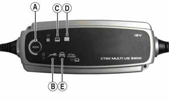
5. By pushing the Mode button (A) on the left side of the charger, select the Normal Charge Icon (E). The Normal Charge Indicator (C) should illuminate on the upper left portion of the charger.
NOTE: If the meter shows more than 1 ohm of resistance, replace the switch.
6. The battery will charge to 95% of its capacity at which time the Maintenance Charge Indicator (D) will illuminate.
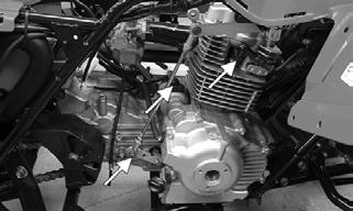
Ignition Coil
NOTE: For optimal charge and performance, leave the charger connected to the battery for a minimum 1 hour after the Maintenance Charge Indicator (D) illuminates. If the battery becomes hot to the touch, stop charging. Resume after it has cooled.
7. Once the battery has reached full charge, unplug the charger from the 110-volt electrical outlet. NOTE: If, after charging, the battery does not perform to operator expectations, bring the battery to an authorized dealer for further troubleshooting.
9. The meter must show less than 1 ohm.
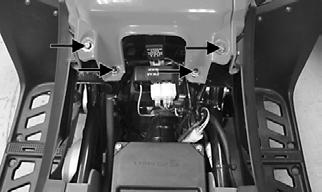
The ignition coil is on the right side of the frame in front of the engine. RESISTANCE
CAUTION Always disconnect the battery when performing resistance tests to avoid damaging the multimeter.
NOTE: For these tests, the meter selector must be set to the OHMS position. Primary Winding
Ignition Switch The connector is the white one in front of the steering post.
66
1. Remove the primary connector from the coil; then connect the red tester lead to the primary terminal and the black tester lead to ground. 2. The meter reading must be within specification.