6 minute read
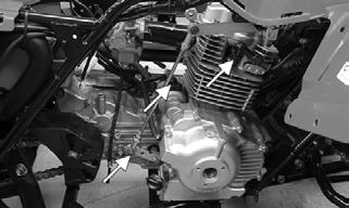
Drive System

CLEANING AND INSPECTING 1.Inspect the sprocket teeth for wear. If they are worn as shown, replace the engine sprocket, rear sprocket, and drive chain as a set.
ATV2185
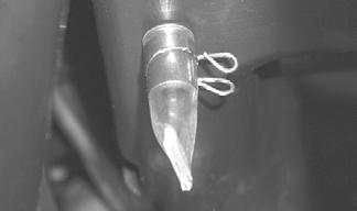
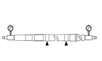
2.Measure the rear axle runout as shown using V blocks and a dial indicator. If the axle runout exceeds 1.5 mm (0.06 in.), the axle must be replaced.
KM480
3.Inspect the dust seals for wear or damage. If any defect is found, replace the dust seal. 4.Inspect the axle bearings by rotating them by hand. If any roughness, binding, or excessive looseness is found, replace the axle bearings. NOTE: If the axle bearings are replaced, replace the
dust seals with new ones. Always pack the bearings with a good quality wheel bearing grease.
Removing Bearings 1.Remove the dust seals using an appropriate seal removal tool; then using an appropriate driver, drive the bearings out of the axle housing. NOTE: Do not reuse bearings after removal. 2.Clean the axle housing and inspect for cracks, elongated holes, and wear in bearing bores.
Installing Bearings 1.Pack the new bearings with a good quality wheel bearing grease; then install the right bearing first using an appropriate bearing installer. 2.Install the left bearing; then install new dust seals and lightly coat the lips with grease.
INSTALLING 1.Slide the axle into the axle housing from the right side; then apply multipurpose grease to all splined areas of the axle.
2.Install the sprocket and sprocket hub on the axle and secure with the nuts; then tighten securely. Install the drive chain.

KM477
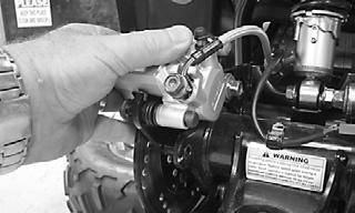
3.On the left side, install the brake disc assembly; then install the brake caliper and secure with the two cap screws. Tighten to 24 ft-lb.
TR236
NOTE: When using a beam-style torque wrench, it
is necessary to calculate the torque value using the following formula due to the offset of the special tool used to tighten the axle nuts. If using a clicker or electronic torque wrench, install the torque wrench at a 90° angle away from the opening of the axle nut wrench.
L x Ts L + Ls = T
T:Torque wrench reading to be calculated Ts:Specified torque value (86 ft-lb) Ls:Tool offset length (center to center) L:Length of torque wrench (handle pivot to headcenter)

ATV2189
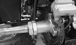
4.Coat the axle threads with red Loctite #271 and install one axle nut; then using the Rear Axle Nut
Wrench, tighten the inner axle nut to calculated specification.
TR235
NOTE: Compress the left hand brake and engage
the brake lever lock to prevent the rear axle from turning
5.Install the outer axle nut and tighten to calculated specification. 6.Adjust the drive chain (see Periodic Maintenance/
Tune-Up); then tighten the two cap screws and adjuster nut. 7.Install the wheel hubs and tighten the rear wheel hub nuts to 50 ft-lb; then install the cotter pins and hub caps. 8.Install the rear wheels and tighten to 40 ft-lb.
Rear Brake Lever/Master Cylinder Assembly
NOTE: The master cylinder is a non-serviceable
component; it must be replaced as an assembly.
REMOVING 1.Connect a clear hose to the bleed screw on the rear brake caliper; then open the bleed screw and pump the brake fluid into a suitable container. Close the bleed screw.
CAUTION
Brake fluid is highly corrosive. Do not spill brake fluid on any surface of the ATV.

TR031A
NOTE: Do not reuse brake fluid. When exposed to
air, brake fluid rapidly absorbs moisture.
2.Remove the brakeline hose union bolt; then remove the cap screws securing the master cylinder assembly to the handlebar. Discard the crush washers from the union bolt.

KM800A
3.Remove the brake lever, brake light switch, and brake lever lock.
INSPECTING 1.Inspect the pivot bolt securing the brake lever for wear.
2.Inspect the brake lever for elongation of the pivot hole.
3.Inspect the reservoir for cracks and leakage. 4.Inspect the brake hose for cracks and deterioration and the condition of the fittings (threaded and compression). 5.Inspect the brake light switch for corrosion, cracks, missing or broken mounting tabs, or broken and frayed wiring. NOTE: If the brake light switch is determined to be
not serviceable, see Lights.
INSTALLING 1.Install the brake light switch on the master cylinder; then install the brake lever and brake lever lock.
2.Install the master cylinder assembly on the handlebar engaging the alignment stud in the hole in the handlebar; then secure with the master cylinder clamp and two cap screws. Make sure the UP arrow on the clamp is directed upward.

KM800B
3.Tighten the cap screw (1) to 9 ft-lb; then tighten the cap screw (2) to 9 ft-lb.
KM800B
4.Using new crush washers, secure the brake hose to the master cylinder with the brake hose union bolt.
Tighten to 24 ft-lb.
KM800A
5.Fill the master cylinder with DOT 4 brake fluid; then bleed the system.
Troubleshooting Drive System
Problem: Braking Poor Condition
1. Pad worn 2. Brake fluid leaking 3. Hydraulic system entrapped air 4. Master cylinder/brake cylinder seal worn
Problem: Brake lever travel excessive Condition
1. Hydraulic system entrapped air 2. Brake fluid low 3. Brake fluid incorrect 4. Piston seal — cup worn
Problem: Brake fluid leaking Condition
1. Connection joints loose 2. Hose cracked 3. Piston seal worn
Remedy
1.Replace pads 2.Repair — replace hydraulic system 3.Bleed hydraulic system 4.Replace appropriate cylinder
Remedy
1.Bleed hydraulic system 2.Add fluid to proper level/bleed system 3.Replace with correct fluid 4.Replace master cylinder
Remedy
1.Tighten joint 2.Replace hose 3.Replace master/brake cylinder
Suspension
The following suspension system components should be inspected periodically to ensure proper operation:
A.Shock absorber rods not bent, pitted, or damaged.
B.Rubber damper not cracked, broken, or missing.
C.Shock absorber body not damaged, punctured, or leaking.
D.Shock absorber eyelets not broken, bent, or cracked.
E.Shock absorber eyelet bushings not worn, deteriorated, cracked, or missing. F.Shock absorber spring not broken or sagging.
Front Shock Absorbers
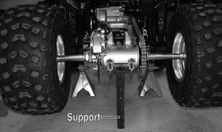
REMOVING 1.Secure the ATV on a support stand to elevate the wheels and to release load on the suspension.
2.Remove the cap screws and nuts securing each shock absorber to the A-arm and frame.
! WARNING
Make sure the ATV is solidly supported on the support stand to avoid injury.

TR009
CLEANING AND INSPECTING 1.Clean the shock absorbers in parts-cleaning solvent. 2.Inspect each shock rod for nicks, pits, bends, and oily residue. 3.Inspect the springs, spring retainers, shock rods, shock bodies, and eyelets for cracks, leaks, and bends.

INSTALLING 1.Install each shock absorber to the frame and A-arm with cap screws and nuts. Tighten all nuts to 29 ft-lb.
2.Remove the ATV from the support stand.
CAUTION
Do not tighten the nut beyond the recommended specification or the shock eyelet or mount WILL be damaged.
Rear Shock Absorber
REMOVING 1.Secure the ATV on a support stand to elevate the wheels and to release load on the suspension.
2.Remove the rear shield plate from the swing arm; then remove the lower shock mounting nut and cap screw. ! WARNING
Make sure the ATV is solidly supported on the support stand to avoid injury.

TR231
NOTE: Support the swing arm with a block of wood