11 minute read
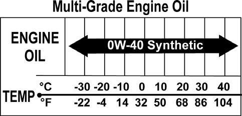
Fuel/Lubrication/Cooling

TR207B
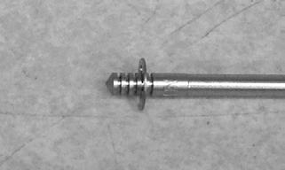
4.Secure the needle jet holder with a wrench; then remove the main jet.

KC0030A
5.Remove the needle jet holder; then remove the slow jet.
CLEANING AND INSPECTING. ! WARNING
When drying components with compressed air, always wear safety glasses.
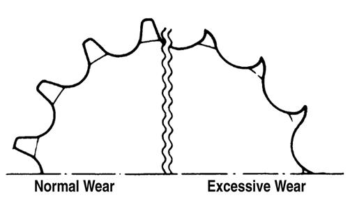
CAUTION
DO NOT place any non-metallic components in partscleaning solvent because damage or deterioration will result.
1.Place all metallic components in a wire basket and submerge in carburetor cleaner. 2.Soak for 30 minutes; then rinse with clean, hot water. 3.Wash all non-metallic components with soap and water. Rinse thoroughly. 4.Dry all components with compressed air only making sure all holes, orifices, and channels are unobstructed.
5.Inspect the carburetor body for cracks, nicks, stripped threads, and any imperfections in the casting. 6.Inspect float for damage. 7.Inspect gasket and O-rings for distortion, tears, or noticeable damage. 8.Inspect tips of the jet needle and the needle jet for wear, damage, or distortion. 9.Inspect the slow jet and main jet for obstructions or damage. NOTE: If the slow jet is obstructed, the mixture will
be extremely lean at idle and part-throttle operation.
10.Inspect the float valve for wear or damage. 11.Inspect the carburetor mounting flange for damage and tightness.
ASSEMBLING NOTE: Note the locations of the jets and holder
during assembling procedures.
TR207B
1.Install the slow jet. Tighten securely. 2.Install the main jet into the needle jet holder and tighten securely; then install the needle jet holder assembly into the carburetor and tighten securely. 3.Place the float assembly (with float valve) into position and secure to the carburetor with the float pin.

TR205A
NOTE: Check float arm height by placing the car-
buretor on its side w/float contacting the needle; then measure with a caliper the height when the float arm is in contact with the needle valve. Float arm height should be 14.8 mm.

TR220
4.Place the float chamber into position making sure the
O-ring is properly positioned; then secure with the
Phillips-head screws.
TR204A

TR203A
INSTALLING 1.If removed, connect the vent hose onto the carburetor.
2.If the throttle valve was removed, install the jet needle (C), needle holder (B), and spring (A) into the throttle valve (D) making sure the E-clip on the needle is in the fourth groove (counting from the top); then connect it to the throttle cable.

TR215A
TR216
TR214
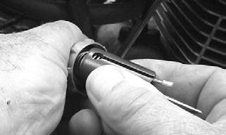
3.Slide the throttle valve into the carburetor making sure the alignment pin in the carburetor engages in the throttle valve groove; then secure the assembly into the carburetor with the cap and tighten securely.
TR202
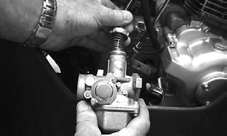
TR053
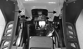
4.Connect the fuel hose to the carburetor and secure with the clamp; then connect the choke cable and tighten the screw securely. 5.Making sure the O-ring is in position on the carburetor, position the carburetor onto the intake pipe and secure with two nuts. Tighten securely. 6.Install the air filter and secure the inlet boot to the carburetor with the clamp; then install two cap screws to secure the air filter housing to the frame and tighten securely. 7.Turn the gas tank shut-off valve to the ON position and check for leaks; then start the engine and adjust the idle as required (see Engine RPM (Idle) in this section). 8.Install the left-side heat shield and seat.
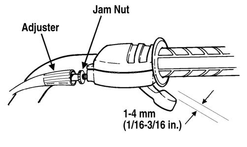
Throttle Cable Free-Play

To adjust throttle cable free-play, use the following procedure.
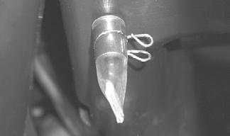
1.Slide the rubber boot away from the adjuster; then loosen the jam nut (1) from the throttle cable adjuster (2).

KM111A
2.Turn the adjuster until the throttle cable has proper free-play of 1-4 mm (1/16-3/16 in.) at the lever.
TXA057
3.Tighten the jam nut against the throttle cable adjuster securely; then slide the rubber boot over the adjuster.
Engine RPM (Idle)
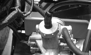
To properly adjust the idle RPM, a tachometer is necessary. To adjust idle RPM, use the following procedure. NOTE: The idle adjustment screw is located on the
right side of the carburetor.
TR030A
1.With the transmission in neutral, start the engine and warm it up to normal operating temperature. 2.Turn the idle adjustment screw clockwise one turn past the recommended RPM setting; then turn it counterclockwise to the correct setting of 1600-1800
RPM.
! WARNING
Adjust the idle to the correct RPM. Make sure the engine is at normal operating temperature before adjusting the idle RPM.
! WARNING
Whenever any maintenance or inspection is made on the fuel system during which there may be fuel leakage, there should be no welding, smoking, open flames, etc., in the area.
REMOVING 1.Turn the gas tank valve to the OFF position. 2.Remove the seat.
3.Disconnect the hose from the carburetor to the gas tank at the carburetor; then remove the gas tank cover.
4.Remove the cap screws securing the gas tank to the frame.
KM327A
5.Remove the vent hose; then remove the gas tank.
CLEANING AND INSPECTING 1.Clean all gas tank components with parts-cleaning solvent.
2.Inspect all hoses for cracks or leaks. 3.Inspect gas tank valve, tank cap, and tank for leaks, holes, and damaged threads. 4.Inspect the gas gauge for proper operation.
INSTALLING 1.Place the gas tank into position on the frame; then install the cap screws. Tighten securely. 2.Connect the gas hose from the carburetor. 3.Install the vent hose; then fill the gas tank with gasoline.
4.Turn the gas tank valve to the ON position and inspect for leakage. 5.Install the seat. The ATV has a valve attached to the gas tank. There are three positions: ON, RES, and OFF.

KM043A
In the OFF position, the valve will not allow gasoline to flow to the carburetor. In the ON position (the normal operating position), gasoline will flow from the tank to the carburetor. In this position 4.54 L (1.2 U.S. gal.) will remain in the tank as a reserve quantity. Moving the valve to the RES position will allow the operator to use the remaining gasoline in the tank. When turning the valve to any of the three positions, make sure the indicator is pointed directly at the position desired.
REMOVING/INSPECTING ! WARNING
Drain the gas tank prior to this procedure.
1.Remove the gas hose from the valve by releasing the clamp. 2.Remove the two machine screws securing the valve; then remove the valve. Account for the gasket. 3.Inspect the gasket and valve/tank mating surfaces for damage or deterioration. 4.Inspect for and remove any obstructions in the valve.
INSTALLING 1.Place the valve and gasket into position on the tank and secure with the machine screws. Tighten securely. 2.Install the gas hose onto the valve with the clamp.

KM427A
Oil Pump
NOTE: Whenever internal engine components wear
excessively or break and whenever oil is contaminated, the oil pump should be disassembled, cleaned, and inspected.
NOTE: The oil pump is not a serviceable compo-
nent. If the pump is defective, the oil pump must be replaced.
REMOVING/DISASSEMBLING 1.Remove the oil pump from the engine (see Engine/
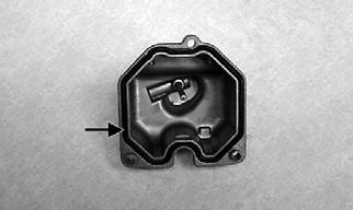
Transmission — Right-Side Components). 2.Remove the Phillips-head screw on the back side of the pump and separate the pump housing and cover.
Note the position of the inner and outer rotors and alignment pin for assembly. 3.Remove oil pump components.
CLEANING AND INSPECTING NOTE: If any part is worn excessively, cracked, or
damaged in any way, the oil pump must be replaced.
1.Clean all oil pump components. 2.Inspect the rotors for scoring and gouges. 3.Inspect the alignment pin, driveshaft, and driven sprocket for damage. 4.Inspect the pump housing and cover for cracks or damage.
ASSEMBLING/INSTALLING 1.Place the rotors into the pump housing making sure the alignment pin is in the groove of the rotor. 2.Place the cover onto the pump housing. 3.Secure the pump with the Phillips-head screw coated with red Loctite #271.
4.Install the oil pump into the engine (see Engine/
Transmission — Right-Side Components).
Troubleshooting
Problem: Starting impaired Condition Remedy
1. Slow jet obstructed 1.Clean jet 2. Slow jet passage obstructed 2.Clean passage 3. Carburetor leaking air 3.Tighten — adjust — replace gasket 4. Choke valve not operating properly 4.Check — adjust choke/choke cable
Problem: Idling or low speed impaired Condition Remedy
1. Slow jet obstructed — loose 1.Clean — tighten jet 2. Slow jet outlet obstructed 2.Clean outlet 3. Choke valve not fully open 3.Adjust choke 4. Float height incorrect 4.Adjust float height
Problem: Medium or high speed impaired Condition Remedy
1. High RPM “cut out” against RPM limiter 1.Shift into higher gear — decrease RPM speed 2. Main jet obstructed 2.Clean main jet 3. Needle jet obstructed 3.Clean needle jet 4. Filter obstructed 4.Clean filter 5. Float height incorrect 5.Adjust float height 6. Starter valve not fully open 6.Adjust choke/choke cable
Problem: Overflow and fuel level fluctuations Condition Remedy
1. Float valve worn — damaged 1.Replace valve 2. Float valve spring broken 2.Replace spring 3. Float fuel logged 3.Replace float 4. Float valve dirty 4.Clean valve 5. Float height too high — too low 5.Adjust float height
Electrical System
This section has been organized into sub-sections which show procedures for the complete servicing of the ATV electrical system. The electrical connections should be checked periodically for proper function. In case of an electrical failure, check fuses, connections (for tightness, corrosion, damage), and/or bulbs.
SPECIAL TOOLS A number of special tools must be available to the technician when performing service procedures in this section. Refer to the current Special Tools Catalog for the appropriate tool description. NOTE: When indicated for use, each special tool
will be identified by its specific name, as shown in the chart below, and capitalized.
NOTE: Special tools are available from the Textron
Off Road Service Parts Department.
Description
Fluke Model 77 Multimeter
p/n
0644-559 MaxiClips 0744-041 Tachometer 0644-275 Timing Light 0644-296
TESTING ELECTRICAL COMPONENTS All of the electrical tests should be made using the Fluke Model 77 Multimeter. If any other type of meter is used, readings may vary due to internal circuitry. When troubleshooting a specific component, always verify first that the fuse(s) are good, that the bulb(s) are good, that the connections are clean and tight, that the battery is fully charged, and that all appropriate switches are activated. NOTE: For absolute accuracy, all tests should be
made at room temperature of approximately 68° F.
Battery
The battery is located under the seat. After being in service, batteries require regular cleaning and recharging in order to deliver peak performance and maximum service life. The following procedure is recommended for cleaning and maintaining a sealed battery. Always read and follow instructions provided with battery chargers and battery products. NOTE: Refer to all warnings and cautions provided
with the battery or battery maintainer/charger.
Loss of battery charge may be caused by ambient temperature, ignition OFF current draw, corroded terminals, self discharge, frequent start/stops, and short engine run times. Frequent winch usage, snowplowing, extended low RPM operation, short trips, and high amperage accessory usage are also reasons for battery discharge.
Maintenance Charging NOTE: Use the CTEK Multi US 800 or the CTEK
Multi US 3300 for battery maintenance charging. Maintenance charging is required on all batteries not used for more than two weeks or as required by battery drain.

800A
1.When charging a battery in the vehicle, be sure the ignition switch is in the OFF position. 2.Clean the battery terminals with a solution of baking soda and water.
NOTE: The sealing strip should NOT be removed
and NO fluid should be added.
3.Be sure the charger and battery are in a well-ventilated area. Be sure the charger is unplugged from the 110-volt electrical outlet.
4.Connect the red terminal lead from the charger to the positive terminal of the battery; then connect the black terminal lead of the charger to the negative terminal of the battery. NOTE: Optional battery charging adapters are
available from your authorized dealer to connect directly to your vehicle from the recommended chargers to simplify the maintenance charging process. Check with your authorized dealer for proper installation of these charging adapter connectors.
5.Plug the battery charger into a 110-volt electrical outlet.
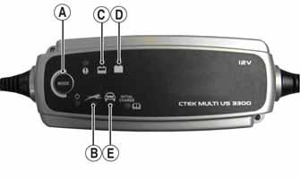
6.If using the CTEK Multi US 800, there are no further buttons to push. If using the CTEK Multi US 3300, press the Mode button (A) at the left of the charger until the Maintenance Charge Icon (B) at the bottom illuminates. The Normal Charge Indicator (C) should illuminate on the upper portion of the battery charger. NOTE: The maintainer/charger will charge the bat-