10 minute read
Steering/Body/Controls

TR241A
CLEANING AND INSPECTING 1.Clean all body components with soap and water. 2.Inspect the body and fenders for cracks. 3.Inspect threaded areas of all mounting studs for stripping. 4.Inspect for missing decals.
INSTALLING 1.Place the front and rear fenders into position on the frame and secure with the existing hardware; then install the gas tank cover. Tighten all fasteners securely. 2.Connect the headlight and taillight connectors; then install the shift knob.
3.Making sure the locating tabs engage the appropriate slots in the fenders, install the side panels.

TR240B
4.Install the mud guards and secure to the fenders and foot rest supports with the existing hardware. Make sure all locating tabs are appropriately engaged with the fenders and side panels.

TR240A
5.Install the front center cover; then install the front and rear racks. Tighten all fasteners securely. 6.Install the battery; then connect the positive battery cable, negative battery cable, and install the battery cover.
NOTE: Always install the positive cable first; then
install the negative cable.
7.Install the seat making sure it locks securely in place.
Steering Post Cover/ Instrument Pod
REMOVING 1.Remove the reinstallable rivet on the front of the instrument pod and the two cap screws on the rear; then lift the assembly off and disconnect the speedometer cable.
2.Remove the self-tapping screw securing the LCD gauge assembly to the instrument pod; then remove the LCD gauge. NOTE: The LCD gauge is not a serviceable compo-
nent. If any functions are incorrect or indicator lights do not illuminate, the LCD gauge must be replaced.
INSTALLING 1.Connect the main harness connector to the LCD gauge; then connect the ignition harness to the ignition connectors.
2. Place the instrument pod onto the mounting bracket; then secure with the reinstallable rivet and two cap screws.
Steering Post/Tie Rods
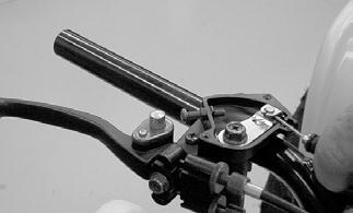
REMOVING 1.Remove the front rack and front center panel. 2.Remove the instrument pod; then remove the cap screws securing the handlebar to the steering post.
Account for two handlebar holders.

KM189A
3.Lift the handlebar out of the lower handlebar holders and lay the handlebar forward. 4.Remove the cotter pins and slotted nuts securing the tie rod ends to the steering post arm; then disconnect the tie rods from the arm.

KM590
5.Remove the cotter pin and slotted nut from the lower end of the steering post; then remove the upper steering shaft support block. Account for a cable guide, two steering support blocks, and the upper steering post bushing.

KM588 KM589
6.Remove the steering post from the ATV.

CLEANING AND INSPECTING 1.Wash the tie rod ends in parts-cleaning solvent. Dry with compressed air. Inspect the pivot area for wear.
Apply a low-temperature grease to the ends.
2.Inspect the tie rods for damaged threads or wear. 3.Inspect the tie rods for cracks or unusual bends. 4.Inspect all welded areas for cracks or deterioration. 5.Inspect the steering post and steering-post holders for cracks, bends, or wear. 6.Inspect the handlebar clamps for cracks or wear. 7.Inspect the handlebar for cracks, wear, or unusual bends.
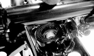
8.Inspect the handlebar grips for damage or wear. 9.Inspect the lower steering post support bearing and seal for wear or cracks.
! WARNING
Always wear safety glasses when using compressed air.
INSTALLING 1.Apply a thin coat of grease to the lips of the lower steering post seals; then lower the steering post into position in the lower steering post bearings.
KM593
2.Apply a thin coat of grease to the upper steering post bushing; then secure the steering post with the support blocks and existing hardware. Tighten to 15 ftlb.
KM589
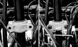
KM595
3.Install the slotted nut on the lower steering post and tighten to 50 ft-lb; then install a new cotter pin.

KM591
4.Place the inner tie rod ends into the steering post arm and tighten the slotted nuts to 29 ft-lb; then install new cotter pins.
KM590
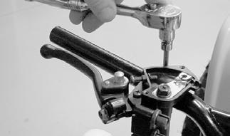
5.Install the handlebar to the steering and tighten the clamp cap screws to 15 ft-lb making sure to tighten the front cap screws first.

KM587

KM597
6.Install the instrument pod; then install the center panel and front rack.
Front Wheel Alignment
1.With the ATV on a level surface, center the handlebar for straight ahead using a suitable means of measuring centering; then adjust tire pressure to specifications (see General Information/Foreword -
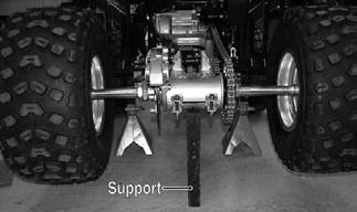
Specifications). 2.Support the front of the ATV with the wheels free to rotate; then center and secure the handlebar. 3.Measure the distance (A) and (B) between the front wheels; then subtract distance (B) from (A). Distance
A - Distance B = Toe-In.
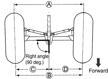
4.Adjust toe-in to 15 mm (0.60 in.); then measure distances (C) and (D). Distances (C) and (D) should be equal. 5.After all the adjustments are to specifications, tighten the tie-rod lock nuts to 22 ft-lb. NOTE: Prior to locking the jam nuts, make sure the
ball joints are at the center of their normal range of motion and at the correct angle.
NOTE: The front wheels do not have to be removed
to adjust the tie rod. Also, care should be taken not to disturb the handlebar position.

Front Brake Lever
! WARNING
After removing and installing of components that are brake-related, ALWAYS check and adjust brakes as necessary before operating the ATV.
REMOVING 1.Remove the right handlebar grip. 2.Remove the cover from the throttle control housing exposing the throttle cable; then remove the cable.
MD2440
MD2439
3. Remove the front brake cables from their adjusters by screwing the adjusters inward to loosen the cables; then pulling them free.

MD2449
4. Loosen the screw securing the front brake lever assembly and slide the assembly off the handlebar.

MD2450
INSTALLING 1.Slide the right brake lever assembly onto the handlebar; do not tighten the screw completely at this time.
MD2452
2. Install the throttle cable into the throttle control housing; then install the cover and secure with the screws.
KM548A
3. Install the brake cable to the lever assembly. NOTE: Before installing a handlebar grip, use con-
tact spray or alcohol to clean the inside of the grip and the handlebar of adhesive residue, oil, or any other contaminant.
4.Apply a liberal amount of Handlebar Grip Adhesive to the inside of the grip; then slide the right grip onto the handlebar. Wipe off any excess adhesive. 5.Tighten the right brake lever assembly screw (from step 1) securely.

MD2461
Throttle Control
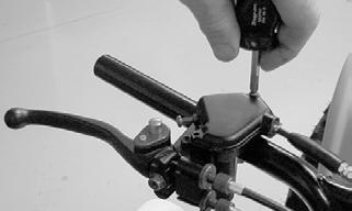
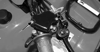
REMOVING 1.Remove the boot from the throttle cable adjuster; then loosen the jam nut and turn the adjuster completely in to loosen the cable. 2.Remove the three machine screws securing the cover to the throttle control; then remove the cover and disengage the throttle cable from the throttle arm. 3.Turn the cable adjuster out of the throttle control housing; then remove the two machine screws securing the throttle control to the handlebar and remove the throttle control.
INSTALLING 1.Making sure the throttle housing upper flat aligns with the alignment mark on the handlebar, place the throttle control into position on the handlebar and secure with the two machine screws; then tighten the machine screws securely.

KM122B
2.Thread the throttle cable into the throttle housing and turn the adjuster completely in; then connect the throttle cable to the throttle arm.
3.Install the throttle housing cover; then adjust the throttle cable.
Headlight — Taillight/Brake Light
HEADLIGHT NOTE: The bulb portion of the headlight is fragile.
HANDLE WITH CARE. When replacing the headlight bulb, do not touch the glass portion of the bulb. If the glass is touched, it must be cleaned with a dry cloth before installing. Skin oil residue on the bulb will shorten the life of the bulb.
! WARNING
Do not attempt to remove the bulb when it is hot. Severe burns may result.
To replace the headlight bulb, use the following procedure.
1.Remove the boot from the back of the headlight housing; then remove the three-wire connector from the bulb.
2.Using care not to bend or deform the spring clip, release the two ends of the spring clip from the light housing; then remove the bulb from the headlight housing.
KM192A
3.Install the new bulb into the headlight housing; then secure with the spring clip.
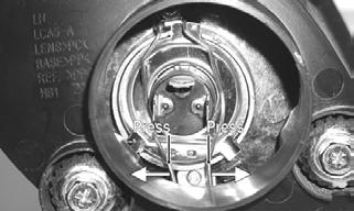
TAILLIGHT-BRAKE LIGHT To replace the taillight-brake light bulb, use the following procedure. 1.Remove the two screws and remove the lens cover.
2.Push the bulb in and turn it counterclockwise. 3.Install the new bulb by turning it clockwise while pushing in. 4.Install the lens cover.
CAUTION
Tighten the lens cover screws only until they are snug.
Troubleshooting
Problem: Handling too heavy or stiff Condition Remedy
1. Front wheel alignment incorrect 1.Adjust alignment 2. Lubrication inadequate 2.Lubricate appropriate components 3. Tire inflation pressure incorrect 3.Adjust pressure 4. Tie rod ends seizing 4.Replace tie rod ends 5. Linkage connections seizing 5.Repair — replace connections
Problem: Steering oscillation Condition Remedy
1. Tires inflated unequally 2. Wheel(s) wobbly 3. Wheel hub cap screw(s) loose — missing 4. Wheel hub bearing worn — damaged 5. Tie rod ends worn — loose 6. Tires defective — incorrect 7. A-arm bushings damaged 8. Bolts — nuts (frame) loose
Problem: Steering pulling to one side Condition
1.Adjust pressure 2.Replace wheel(s) 3.Tighten — replace cap screws 4.Replace bearing 5.Replace — tighten tie rod ends 6.Replace tires 7.Replace bushings 8.Tighten bolts — nuts
Remedy
1. Tires inflated unequally 2. Front wheel alignment incorrect 3. Wheel hub bearings worn — broken 4. Frame distorted 5. Shock absorber defective 1.Adjust pressure 2.Adjust alignment 3.Replace bearings 4.Repair — replace frame 5.Replace shock absorber
Problem: Steering impaired Condition Remedy
1. Tire pressure too high 1.Adjust pressure 2. Steering linkage connections worn 2.Replace connections 3. Cap screws (suspension system) loose 3.Tighten cap screws
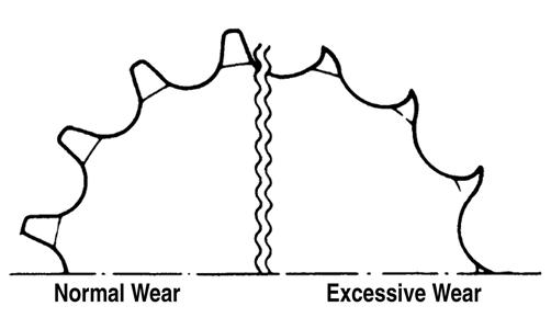
Problem: Tire wear rapid or uneven Condition Remedy
1. Wheel hub bearings worn — loose 1.Replace bearings 2. Front wheel alignment incorrect 2.Adjust alignment
Problem: Steering noise Condition Remedy
1. Cap screws — nuts loose 1.Tighten cap screws — nuts 2. Wheel hub bearings broken — damaged 2.Replace bearings 3. Lubrication inadequate 3.Lubricate appropriate components
Engine/Transmission
This section has been organized into sub-sections which show a progression for the complete servicing of the ATV engine/transmission. To service the center crankcase halves, the engine/transmission must be removed from the frame. To service topside, left-side, and right-side components, the engine/ transmission does not have to be removed from the frame.
NOTE: Use new gaskets, lock nuts, and seals and
lubricating all internal components when servicing the engine/ transmission.
SPECIAL TOOLS A number of special tools must be available to the technician when performing service procedures in this section. Refer to the current Special Tools Catalog for the appropriate tool description. NOTE: When indicated for use, each special tool
will be identified by its specific name, as shown in the chart below, and capitalized.
NOTE: Special tools are available from the Textron
Off Road Service Parts Department.
NOTE: A new ATV and an overhauled ATV engine
require a “break-in” period. The first 10 hours (or 200 miles) are most critical to the life of this ATV. Proper operation during this break-in period will help ensure maximum life and performance from the ATV. Instruct the customer to follow the proper break-in procedure as described in the Operator’s Manual.
Description p/n
Crankcase Separator/Crankshaft Remover 0444-152 Piston Pin Puller 0644-328 Spanner Wrench 0444-192 Flywheel Holder 0444-193 Magneto Rotor Remover 0444-187 Tappet Adjuster 0444-189 Surface Plate 0644-016 Driven Pulley Compressor 0444-195 V Blocks 0644-535 Ring Compressor 0644-378 Valve Spring Compressor 0444-197 Ball Hone 0644-290 Crankshaft Bearing Puller 0444-194 Blind Bearing Puller Kit 0444-196 Bearing/Seal Driver Kit 0444-190