44 minute read
Engine/Transmission

Troubleshooting
Problem: Engine will not start or is hard to start (Compression too low) Condition Remedy
1. Valve clearance out of adjustment 2. Valve guides worn — seated poorly 3. Valves mistimed 4. Piston rings worn excessively 5. Cylinder bore worn 6. Spark plug seating poorly 7. Starter motor cranks too slowly - does not turn 1. Adjust clearance 2. Repair — replace guides 3. Adjust valve timing 4. Replace rings 5. Replace cylinder 6. Tighten plug 7. See Starter Motor
Problem: Engine will not start or is hard to start (No spark) Condition Remedy
1. Spark plug fouled 2. Spark plug wet 3. Magneto defective 4. CDI unit defective 5. Ignition coil defective 6. High-tension lead open — shorted
1. Clean — replace plug 2. Clean — dry plug 3. Replace magneto 4. Replace CDI unit 5. Replace ignition coil 6. Replace high tension lead
Problem: Engine will not start or is hard to start (No fuel reaching the carburetor) Condition Remedy
1. Gas tank vent hose obstructed 2. Carburetor inlet needle defective 3. Fuel hose obstructed 4. Fuel screens obstructed 1. Clean vent hose 2. Replace needle 3. Clean — replace hose 4. Clean — replace inlet screen - valve screen
Problem: Engine stalls easily Condition Remedy
1. Spark plug fouled 2. Magneto defective 3. CDI unit defective 4. Carburetor jets obstructed 5. Valve clearance out of adjustment 1. Clean plug 2. Replace magneto 3. Replace CDI unit 4. Clean jets 5. Adjust clearance
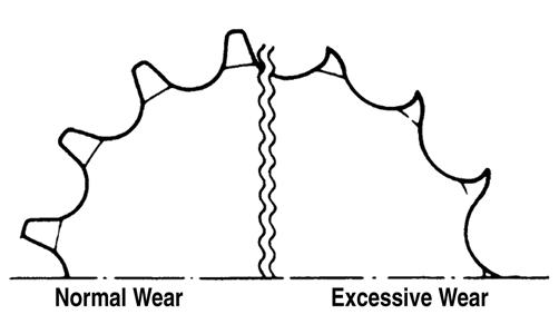
Problem: Engine noisy (Excessive valve chatter) Condition Remedy
1. Valve clearance too large 2. Valve spring(s) weak — broken 3. Rocker arm — rocker arm shaft worn 4. Camshaft worn 1. Adjust clearance 2. Replace spring(s) 3. Replace arm — shaft 4. Replace camshaft
Problem: Engine noisy (Noise seems to come from piston) Condition Remedy
1. Piston — cylinder worn 2. Combustion chamber carbon buildup 3. Piston pin — piston pin bore worn 4. Piston rings — ring groove(s) worn
1. Replace — service piston — cylinder 2. Clean chamber 3. Replace — service pin — bore 4. Replace rings — piston
Problem: Engine noisy (Noise seems to come from timing chain) Condition Remedy
1. Chain stretched 2. Sprockets worn 3. Tension adjuster malfunctioning 1. Replace chain 2. Replace sprockets 3. Repair — replace adjuster
Problem: Engine noisy (Noise seems to come from crankshaft) Condition Remedy
1. Bearing worn — burned 2. Lower rod-end bearing worn — burned 3. Connecting rod side clearance too large
1. Replace bearing 2. Replace bearing 3. Replace thrust washer(s)
Problem: Engine noisy (Noise seems to come from transmission) Condition Remedy
1. Gears worn — rubbing 2. Splines worn 3. Primary gears worn — rubbing 4. Bearings worn 5. Bushing worn
1. Replace gears 2. Replace shaft(s) 3. Replace gears 4. Replace bearings 5. Replace bushing
Problem: Engine noisy (Noise seems to come from secondary-transmission/right-side cover) Condition Remedy
1. Gears — shaft(s) worn 2. Bearing(s)/bushing(s) damaged 1. Replace gears — shafts 2. Replace bearing(s)/bushing(s)
Problem: Centrifugal clutch slipping Condition Remedy
1. Clutch shoes worn 2. Clutch housing excessively worn 3. Drive belt slipping — worn 1. Replace shoes 2. Replace clutch housing 3. Replace drive belt
Problem: Engine noisy (Noise seems to come from secondary bevel gear and final driven shaft) Condition Remedy
1. Drive — driven bevel gears damaged — worn 2. Backlash excessive 3. Tooth contact improper 4. Bearing damaged 5. Gears worn — rubbing 6. Splines worn 7. Final driven shaft thrust clearance too large 1. Replace gears 2. Adjust backlash 3. Adjust contact 4. Replace bearing 5. Replace gears 6. Replace shaft(s) 7. Replace thrust washer(s)
Problem: Secondary-transmission will not shift or shift back Condition Remedy
1. Sliding dog broken — worn 2. Gearshift fork broken — worn 3. Shift lever out of adjustment 4. Gearshift cam worn 5. Cam stopper spring weak 6. Gearshift fork shaft worn 7. Engine idle too high 8. Shift linkage out of adjustment 1. Replace dog 2. Replace fork 3. Adjust lever 4. Replace cam 5. Replace spring 6. Replace shaft 7. Adjust engine idle 8. Adjust shift linkage
Problem: Engine idles poorly Condition Remedy
1. Valve clearance out of adjustment 2. Valve seating poor 3. Valve guides defective 4. Rocker arms — arm shaft worn 5. Magneto defective 6. CDI unit defective 7. Spark plug fouled — gap too wide 8. Ignition coil defective 9. Float out of adjustment 10. Jets obstructed
1. Adjust clearance 2. Replace — service seats — valves 3. Replace guides 4. Replace arms — shafts 5. Replace magneto 6. Replace CDI unit 7. Adjust gap — replace plug 8. Replace ignition coil 9. Adjust float height 10. Clean jets
Problem: Engine runs poorly at high speed Condition Remedy
1. High RPM “cut out” against RPM limiter 2. Valve springs weak 3. Valve timing out of adjustment 4. Cams — rocker arms worn 5. Spark plug gap too narrow 6. Ignition coil defective 7. Float level too low 8. Air cleaner element obstructed 9. Fuel hose obstructed 1. Shift into higher gear — decrease speed 2. Replace springs 3. Adjust timing 4. Replace cams — arms 5. Adjust gap 6. Replace ignition oil 7. Adjust float height 8. Clean element 9. Clean — prime hose
Problem: Exhaust smoke dirty or heavy Condition Remedy
1. Oil (in the engine) overfilled — contaminated 2. Piston rings — cylinder worn 3. Valve guides worn 4. Cylinder wall scored — scuffed 5. Valve stems worn 6. Stem seals defective 7. Air cleaner element obstructed 8. Float level too high 1. Drain excess oil — replace oil 2. Replace — service rings — cylinder 3. Replace guides 4. Replace — service cylinder 5. Replace valves 6. Replace seals 7. Clean element 8. Adjust float level
Problem: Engine lacks power Condition Remedy
1. Valve clearance incorrect 2. Valve springs weak 3. Valve timing out of adjustment 4. Piston ring(s) — cylinder worn 5. Valve seating poor 6. Spark plug fouled 7. Rocker arms — shafts worn 8. Spark plug gap incorrect 9. Carburetor jets obstructed 10. Float level out of adjustment 11. Air cleaner element obstructed 12. Oil (in the engine) overfilled — contaminated 13. Intake manifold leaking air 14. Cam chain worn
1. Adjust clearance 2. Replace springs 3. Adjust timing 4. Replace — service rings — cylinder 5. Repair seats 6. Clean — replace plug 7. Replace arms — shafts 8. Adjust gap — replace plug 9. Clean jets 10. Adjust float height 11. Clean element 12. Drain excess oil — change oil 13. Tighten — replace manifold 14. Replace cam chain
Problem: Engine overheats Condition Remedy
1. Carbon deposit (piston crown) excessive 2. Oil low 3. Octane low — gasoline poor 4. Oil pump defective 5. Oil circuit obstructed 6. Gasoline level (in float chamber) too low 7. Intake manifold leaking air 1. Clean piston 2. Add oil 3. Drain — replace gasoline 4. Replace pump 5. Clean circuit 6. Adjust float height 7. Tighten — replace manifold
Removing Engine/ Transmission
Many service procedures can be performed without removing the engine/transmission from the frame. Closely observe the note introducing each sub-section for this important information.
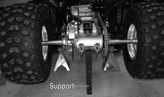
Secure the ATV on a support stand to elevate the wheels.
1.Remove the seat; then remove the left and right side covers and footwells.
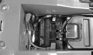
2.Remove the gas tank (see the Fuel/Lubrication/Cooling section). 3.Move the battery cover and disconnect the negative battery cable.
AT THIS POINT
If the technician’s objective is to service/replace leftside cover oil seals, the engine/transmission does not have to be removed from the frame.
! WARNING
Make sure the ATV is solidly supported on the support stand to avoid injury.

TR022A
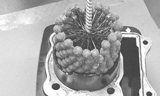
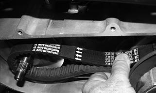
4.Remove the crankcase breather hose from the crankcase ventilator valve; then loosen the intake boot clamp and remove the air filter assembly.
TR050A
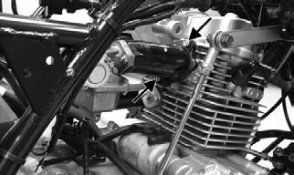
5.Remove the nuts securing the intake to the cylinder head; then remove the intake pipe/carburetor assembly leaving the throttle cable and choke cable connected. Set the assembly aside.

TR054A
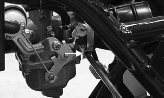
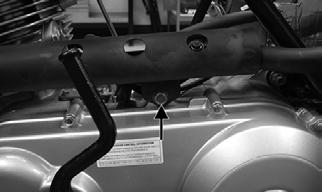
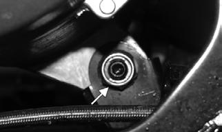
6.From the right side, remove the spark plug cap and starter lead; then disconnect the shift rod from the lower shift arm.
TR059A
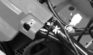
7.Disconnect the AC generator plug; then mark the location of the cable tie and remove the tie.

TR071A
TR072A
8.From the left side, remove the CVT cooling duct clamps; then remove the cooling ducts.
TR063

TR061
9.Disconnect the signal coil, trigger coil, and gear position switch connectors.

TR070A
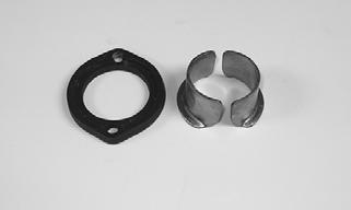
10.Remove the two nuts and two cap screws securing the exhaust pipe/muffler assembly and remove the exhaust assembly. Account for the exhaust flange and two sealing wedges.
TR067A TR073A

TR062A
TR041
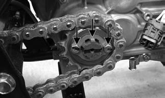
11.Remove the drive sprocket guard; then remove the two cap screws and retainer securing the drive sprocket to the driveshaft. Remove the drive sprocket.
TR075A
NOTE: It may be necessary to loosen the drive
chain to remove the sprocket (see Periodic Maintenance/Tune-Up — Drive Chain).
12.Remove the three through-bolts securing the engine to the frame; then remove the left front mounting bracket from the frame.

KM414A

KM333A
KM325A
13.Remove the engine/transmission assembly from the frame tilting the rear of the assembly upwards and lifting out the left side.
Top-Side Components
NOTE: For efficiency, it is preferable to remove and disassemble only those components which need to be addressed and to service only those components. The technician should use discretion and sound judgment.
AT THIS POINT
To service any one specific component, only limited disassembly of components may be necessary. Note the AT THIS POINT information in each sub-section.
Removing Top-Side Components
A.Valve Cover B.Cylinder Head NOTE: Remove the spark plug and timing inspec-
tion plug; then rotate the crankshaft to top-dead-center of the compression stroke.
1.Remove the cap screws securing the cylinder head cover. Account for the O-ring.

KM703
NOTE: Keep the mounting hardware with the cover
for assembly purposes.
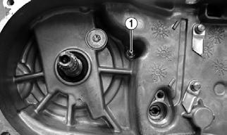
2.Remove the plug (A) from the cam chain tensioner; then turn the cam chain tensioner screw clockwise to release the chain tension.

TXA059A

TXA060
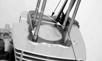
3.Using a crisscross pattern, loosen the four nuts securing the camshaft holder to the cylinder head. Use 2-3 steps until the nuts are all free; then remove the camshaft holder. Account for four washers and two alignment pins.

KM706A

KM707A
4.Remove the camshaft gear from the cam chain; then secure the timing chain so it will not fall into the engine. Remove the camshaft. 5.Remove the two cap screws securing the cylinder head to the cylinder; then remove the cylinder head.
Account for two alignment pins and a cylinder head gasket.
TXA061
6.Remove the cam chain guide; then remove the cylinder. Support the piston with rubber bands or other suitable supports. Account for two dowel pins and the cylinder gasket.
AT THIS POINT
To service valves and cylinder head, see Servicing TopSide Components sub-section.
AT THIS POINT
To inspect cam chain guide, see Servicing Top-Side Components sub-section.
C.Cylinder D.Piston NOTE: Steps 1-6 in the preceding sub-section must
precede this procedure.
AT THIS POINT
To service cylinder, see Servicing Top-Side Components sub-section.
CAUTION
When removing the cylinder, be sure to support the piston to prevent damage to the crankcase and piston.
7.Using a needle nose pliers, remove one piston pin circlip. Take care not to drop it into the crankcase.

KM451
8.Using Piston Pin Puller, remove the piston pin.
Account for the opposite-side circlip. Remove the piston. NOTE: It is advisable to remove the opposite-side
circlip prior to using the puller.
NOTE: Support the connecting rod with rubber
bands to avoid damaging the rod or install a connecting rod holder.
NOTE: If the existing rings will not be replaced with
new rings, note the location of each ring for proper installation. When replacing with new rings, replace as a complete set only. If the piston rings must be removed, remove them in this sequence.
CAUTION
Do not allow the connecting rod to go down inside the crankcase. If the rod is down inside the crankcase and the crankshaft is rotated, severe damage will result.
A.Starting with the top ring, slide one end of the ring out of the ring-groove. B.Remove each ring by working it toward the dome of the piston while rotating it out of the groove.
AT THIS POINT
To service piston, see Servicing Top-Side Components sub-section.
AT THIS POINT
To service center crankcase components only, proceed to Removing Left-Side Components.
Servicing Top-Side Components
VALVE ASSEMBLY When servicing valve assembly, inspect valve seats, valve stems, valve faces, and valve stem ends for pits, discoloration, or other signs of abnormal wear. NOTE: Whenever a valve is out of tolerance, it must
be replaced.
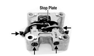
Cleaning/Inspecting Camshaft Holder 1.Remove the rocker arm shafts, rocker arms, and stop plate from the camshaft holder.
KM708A
2.Inspect the camshaft holder for cracks, distortion, or galling. 3.Inspect the rocker arm shafts for blue discoloration or scoring.

KM710A
Removing Valves NOTE: Keep all valves and valve components as a
set. Note the original location of each valve set for use during installation. Return each valve set to its original location during installation.
1.Using a valve spring compressor, compress the valve springs and remove the valve cotters. Account for an upper spring retainer.

KM717A
2.Remove the valve seal, valve springs, and the lower remaining spring seat. Discard the valve seal. NOTE: The valve seals must be replaced. 3.Invert the cylinder head and remove the valves.
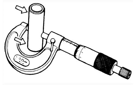
Measuring Valve Stem/Valve Guide Clearance 1.Using a micrometer, measure the valve stem outside diameter; then using a suitable snap gauge and micrometer, measure the valve guide inside diameter. 2.Acceptable clearance must be within specifications.
Inspecting Valve Face Inspect the valve face for pitting, grooving, or discoloration. Replace any valve that is damaged.
CYLINDER HEAD ASSEMBLY NOTE: If the cylinder head cannot be trued, it must
be replaced.
Cleaning/Inspecting Cylinder Head 1.Using a non-metallic carbon removal tool, remove any carbon build-up from the combustion chamber making sure not to nick, scrape, or damage the combustion chamber or the sealing surface. 2.Inspect the spark plug hole for any damaged threads.
Repair damaged threads using a “heli-coil” insert. 3.Place the cylinder head on the surface plate covered with #400 grit wet-or-dry sandpaper. Using light pressure, move the cylinder head in a figure-eight motion. Inspect the sealing surface for any indication of high spots. A high spot can be noted by a bright metallic finish. Correct any high spots before assembly by continuing to move the cylinder head in a figure-eight motion until a uniform bright metallic finish is attained.
CAUTION
Water or parts-cleaning solvent must be used in conjunction with the wet-or-dry sandpaper or damage to the sealing surface may result.
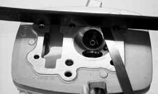
Measuring Cylinder Head Distortion 1.Remove any carbon buildup in the combustion chamber.
2.Lay a straightedge across the cylinder head; then using a feeler gauge, check the distortion factor between the head and the straightedge. 3.Maximum distortion must not exceed specifications.
TXA058
Measuring Camshaft Lobe Height 1.Using a calipers, measure each cam lobe height.
Inspecting Camshaft Bearing Journal 1.Inspect the bearing journal for scoring, seizure marks, or pitting. 2.If excessive scoring, seizure marks, or pitting is found, the cylinder head assembly must be replaced.
Measuring Rocker Arm/Shaft Clearance 1.Using a dial calipers, measure the inside diameter of the rocker arm; then measure the outside diameter of the rocker arm shaft.
2.Acceptable clearance must not exceed specifications.
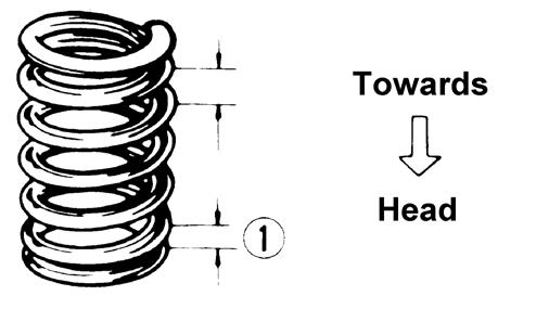
Installing Valves 1.Apply grease to the inside surface of the valve seals; then place a lower spring seat and valve guide seal over each valve guide. 2.Insert each valve into its original valve location. 3.Install the valve springs with the closest coils toward the cylinder head.
ATV-1011A
4.Place a spring retainer over the valve springs; then using the valve spring compressor, compress the valve springs and install the valve cotters.
KM717A
PISTON ASSEMBLY NOTE: Whenever a piston, rings, or pin are out of
tolerance, they must be replaced.
Inspecting Piston 1.Inspect the piston for cracks in the piston pin, dome, and skirt areas.
2.Inspect the piston for seizure marks or scuffing.
Repair with #400 grit wet-or-dry sandpaper and water or honing oil. NOTE: If scuffing or seizure marks are too deep to
correct with the sandpaper, replace the piston.
3.Inspect the perimeter of each piston for signs of excessive “blowby.” Excessive “blowby” indicates worn piston rings or an out-of-round cylinder.
Removing Piston Rings 1.Starting with the top ring, slide one end of the ring out of the ring-groove.

CC400D
2.Remove each ring by working it toward the dome of the piston while rotating it out of the groove. NOTE: If the existing rings will not be replaced with
new ones, note the location of each ring for proper installation. When installing new rings, install as a complete set only.
Measuring Piston-Ring End Gap (Installed) 1.Place each piston ring in the wear portion of the cylinder. Use the piston to position each ring squarely in the cylinder. 2.Using a feeler gauge, measure each piston-ring end gap. Acceptable ring end gap must not exceed specifications.

KM452
Measuring Piston Pin (Outside Diameter) and Piston-Pin Bore 1.Measure the piston pin outside diameter at each end and in the center. If measurement is not within specifications, the piston pin must be replaced.
ATV-1070
2.Inspect and measure the connecting rod small end. If the measurement exceeds specifications, the connecting rod must be replaced (see Servicing Center
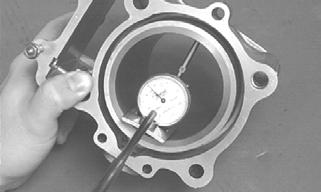
Crankcase Components). 3.Insert an inside dial indicator into the piston-pin bore. The diameter must not exceed specifications.
Take two measurements to ensure accuracy.

ATV-1069
Measuring Piston Skirt/Cylinder Clearance 1.Measure the cylinder front to back in six places.
CC127D
2.Measure the corresponding piston diameter at a point 5 mm above the piston skirt at a right angle to the piston-pin bore. Subtract this measurement from the largest measurement in step 1. The difference (clearance) must be within specifications.
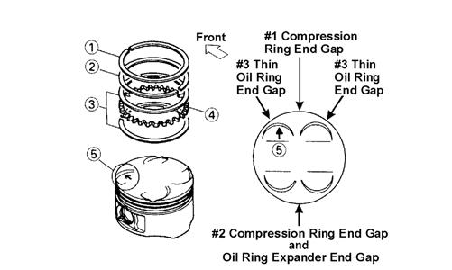
Installing Piston Rings 1.Install ring expander (4) in the bottom groove of the piston; then install the thin oil rings (3) over the expander making sure the expander ends do not overlap. Stagger the end gaps of the upper and lower thin oil rings according to the illustration. NOTE: Note the direction of the exhaust side of the
piston (5) for correct ring end gap orientation.
ATV-1085B
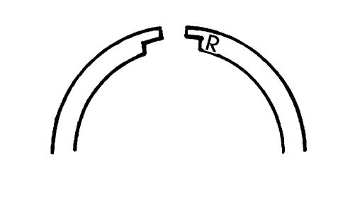
2.Install the compression rings (1 and 2) so the letter on the top surface of each ring faces the dome of the piston. Rotate the rings until the ring end gaps are on directly opposite sides of the piston according to the illustration.
726-306A
CAUTION
Incorrect installation of the piston rings will result in engine damage.
CYLINDER ASSEMBLY NOTE: If the cylinder cannot be trued, it must be
replaced.
Cleaning/Inspecting Cylinder 1.Wash the cylinder in parts-cleaning solvent. 2.Inspect the cylinder for pitting, scoring, scuffing, warpage, and corrosion. If marks are found, repair the surface using a cylinder hone. 3.Place the cylinder on the surface plate covered with #400 grit wet-or-dry sandpaper. Using light pressure, move the cylinder in a figure-eight motion. Inspect the sealing surface for any indication of high spots.
A high spot can be noted by a bright metallic finish.
Correct any high spots before assembly by continuing to move the cylinder in a figure-eight motion until a uniform bright metallic finish is attained.
CAUTION
Water or parts-cleaning solvent must be used in conjunction with the wet-or-dry sandpaper or damage to the sealing surface may result.
Inspecting Cam Chain Guide 1.Inspect cam chain guide for cuts, tears, breaks, or chips. 2.If the chain guide is damaged, it must be replaced.
Honing Cylinder 1.Using a slide gauge and a dial indicator or a snap gauge, measure the cylinder bore diameter in three locations from top to bottom and again from top to bottom at 90° from the first measurements for a total of six measurements. The trueness (out-of-roundness) is the difference between the highest and lowest reading. Maximum trueness (out-of-roundness) must not exceed specifications.
CC127D
2.Wash the cylinder in parts-cleaning solvent. 3.Inspect the cylinder for pitting, scoring, scuffing, and corrosion. If marks are found, repair the surface using a #320 grit ball hone. NOTE: To produce the proper 60° cross-hatch pat-
tern, use a low RPM drill (600 RPM) at the rate of 30 strokes per minute. If honing oil is not available, use a lightweight petroleum-based oil. Thoroughly clean cylinder after honing using soap and hot water. Dry with compressed air; then immediately apply oil to the cylinder bore. If the bore is severely damaged or gouged, replace the cylinder.
CC390D
4.If any measurement exceeds the limit, replace the cylinder.
Installing Top-Side Components
A.Piston B.Cylinder 1.Install the piston on the connecting rod making sure there is a circlip on each side and the open end of the circlip is directed upwards or downwards. NOTE: The piston should be installed so the IN
mark is toward the intake (rear) side of the cylinder.
2.Place the two alignment pins into position. Place the cylinder gasket into position; then place a piston holder (or suitable substitute) beneath the piston skirt and square the piston in respect to the crankcase. 3.Lubricate the inside wall of the cylinder; then using a ring compressor or the fingers, compress the rings and slide the cylinder over the piston. Route the cam chain up through the cylinder cam chain housing; then remove the piston holder and seat the cylinder firmly on the crankcase.
CAUTION
The cylinder should slide on easily. Do not force the cylinder or damage to the piston, rings, cylinder, or crankshaft assembly may occur.
C.Cylinder Head D.Valve Cover NOTE: Steps 1-3 in this sub-section must precede
this procedure.
4.While keeping tension on the cam chain, place the front cam chain guide into the cylinder. 5.Place the head gasket into position on the cylinder. Place the alignment pins into position; then place the head assembly into position on the cylinder making sure the cam chain is routed through the chain cavity.
CAUTION
Care should be taken that the bottom of the chain guide is secured in the crankcase boss.
CAUTION
Keep tension on the cam chain to avoid damaging the crankcase boss.
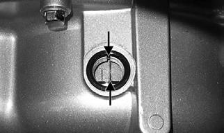
TXA061
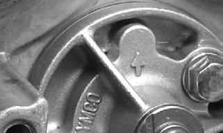
6.Turn the crankshaft as required to align the “T” mark on the rotor/flywheel with the index mark on the right-side crankcase cover.
TR043A
7.With the index hole in the camshaft gear directed away from the cylinder head and the two punch marks aligned with the cylinder head surface, install the timing gear into the cam chain and seat the camshaft into the camshaft journals.

KM715A
8.Install the two alignment pins; then install the camshaft holder and secure with the four cylinder head nuts and washer. Using a crisscross pattern, tighten to 14 ft-lb. Install and tighten the internal cylinder head to cylinder cap screws to 7 ft-lb.
KM707A
KM706A
9.Install the cam chain tensioner assembly and tighten the mounting cap screws (A) to 9 ft-lb; then turn the tensioner screw counterclockwise to tension the cam chain.

TXA060A
10.Install the cam chain tensioner cover bolt and tighten to 36 in.-lb.
11.Check that the cam gear alignment marks are correctly oriented. 12.Install the cylinder head cover with a new O-ring and tighten securely.
Left-Side Components
NOTE: For efficiency, it is preferable to remove and disassemble only those components which need to be addressed and to service only those components. The technician should use discretion and sound judgment.
NOTE: The engine/transmission does not have to be
removed from the frame for this procedure.
AT THIS POINT
To service any one specific component, only limited disassembly of components may be necessary. Note the AT THIS POINT information in each sub-section.
Removing Left-Side Components
A.Kick Starter B.V-Belt Cover C.Drive Pulley D.Driven Pulley/Centrifugal Clutch
Assembly 1.Mark and remove the kick starter lever.

TR082A
2.Remove the cap screws securing the V-belt cover; then remove the cover noting the location of the two dowel pins. Note the condition of the V-belt cover gasket. Replace if damaged.

KM253
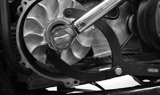
3.Using a suitable holder to prevent the drive pulley from turning, remove the drive pulley nut and starter ratchet; then remove the drive pulley face.
KM365
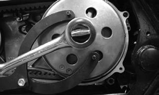
4.Hold the centrifugal clutch with a suitable holder; then remove the clutch retaining nut and clutch collar.
KM364
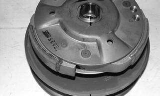
5.Remove the outer clutch housing; then remove the centrifugal clutch, driven pulley, and V-belt.
KM369
6.Remove the wire guides securing the switch harness; then remove the gear position switch. Account for an
O-ring.

TR087A
NOTE: It is very important to note the position of
the roll pin on the gear position switch for assembly purposes. The switch can be installed with the pin 180° from correct position. The indicator lights will not illuminate.
Servicing Left-Side Components
KICK STARTER NOTE: The kick starter is a non-serviceable compo-
nent. If parts are worn excessively, the CVT cover assembly must be replaced.
V-BELT COVER 1.Inspect the bearing for excessive wear, rough or binding when turning, seal condition, and secure mounting in the V-belt cover. NOTE: If the bearing is worn excessively, turns
roughly, or bearing seals are loose, the bearings must be replaced.

KM254
2.Inspect the V-belt cover for cracks, distortion, and loose alignment pins. NOTE: If the V-belt cover is cracked or distorted or
if the bearing is loose in the cover, the cover must be replaced.
DRIVE PULLEY 1.Remove the ramp plate from the movable drive face; then inspect the ramp plate guides and weight roller for damage or excessive wear.

KM256
2.Inspect the face surfaces of the fixed and movable drive faces for grooving, nicks, or discoloration.

KM394A
3.Inspect the drive pulley collar for wear or damage.
Measure the outside diameter of the drive pulley collar sliding surface. The minimum service limit is 26.94 mm.
KM389
DRIVEN PULLEY/CENTRIFUGAL CLUTCH ASSEMBLY Disassembling ! WARNING
This procedure involves relaxing a compressed spring assembly. DO NOT attempt disassembling without the proper tools.
1.Place the driven pulley on a suitable spring compressor; then mark the pulley faces and centrifugal clutch for alignment during assembling.
KM374A
2.Secure the centrifugal clutch with the spring compressor; then remove the drive plate nut.
KM373
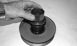
3.Release the spring pressure and remove the centrifugal clutch assembly from the driven pulley.
KM375
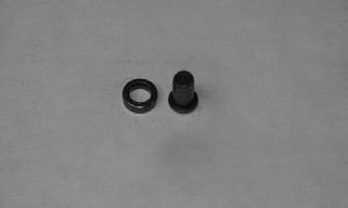
4.Remove the spring and spring seat; then remove the hub collar.


KM384
KM380
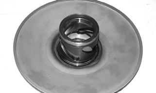
Inspecting 1.Inspect the pulley faces for wear, galling, or grooving.
KM394A
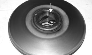
2.Inspect the O-rings on the movable face for nicks, tears, or swelling.

KM380B
KM382A
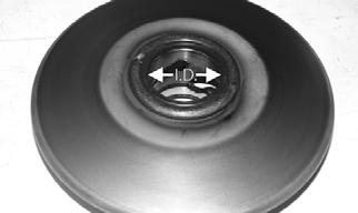
4.Inspect the pins and bushings for wear, flat spots, looseness, or cracking; then measure the inside diameter of the movable driven face bushing. Maximum allowable service limit is 34.06 mm.
KM379
KM382B
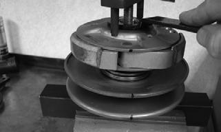
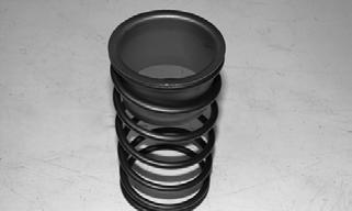
5.Measure the driven face spring free length. If the free length is less than 83.20 mm, the spring must be replaced.

KM376
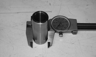
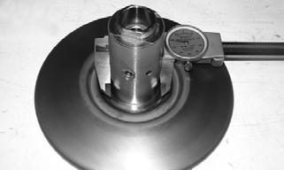
6.Measure the fixed driven face hub outside diameter using a calipers. The minimum service limit is 33.94 mm.
KM378
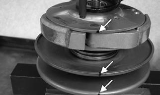
7.Measure the thickness of the centrifugal clutch shoe lining. The minimum service limit for the lining is 2.0 mm.
NOTE: If any shoe lining is below the service limit,
the complete set must be replaced.
Assembling 1.Place the fixed face of the driven pulley on the pulley compressor base. NOTE: Make sure the spacer is on the base or dam-
age to the fixed face will occur when the spring is compressed.

KX571
2.Apply multi-purpose grease to the O-rings and grease seals on the movable face; then install on the fixed face making sure the alignment marks are properly aligned.
KM374A
3.Install the pins and spacers into the fixed face hub; then pack the cam slots in the movable face with multi-purpose grease.
KM384
4.Install the spring seat over the hub and movable face hub.
KM385
5.Place the spring holder on the spring; then install the spring on the pulley assembly.
KM386
6.Place the centrifugal clutch assembly, drive plate nut, and clutch compressor adapter in position; then using the clutch compressor wing nut, compress the clutch spring and install the nut (lightly coated with red
Loctite #271).
KM373
7.Using a suitable holding fixture, tighten the drive plate nut to 43 ft-lb.
Installing Left-Side Components
A.Drive Pulley B.Driven Pulley/Centrifugal Clutch
Assembly C.V-Belt Cover AT THIS POINT
If the gear position switch was removed, install it into the crankcase using a new O-ring. Tighten the cap screw securely.
CAUTION
Make sure to orient the roll-pin with the longer end directed to the rear. Failure to properly orient the switch will result in failure of the neutral and reverse lights to illuminate.

TR088
1.Install the movable drive face and drive pulley collar on the crankshaft.
2.Open the faces of the driven pulley; then insert a suitable wedge between the faces to hold them apart. 3.Place the V-belt around the pulley and push the belt down between the pulley faces; then install the driven pulley/centrifugal clutch assembly onto the driveshaft. Loop the V-belt over the drive pulley collar.

KM262
KM369
4.Place the fixed drive face into position on the crankshaft and engage the splines making sure the splines extend beyond the pulley face hub.
KM263A
5.Install the starter ratchet on the crankshaft making sure to engage the splines; then secure with the drive pulley nut and tighten to 43 ft-lb.
KM365
6.Install the centrifugal clutch housing and clutch collar; then secure with the flange nut (coated with red
Loctite #271) and tighten to 40 ft-lb.
KM253
KM368
7.Install the alignment pins and a new gasket on the crankcase; then install the CVT cover and secure with the cap screws. Tighten to 7 ft-lb.
Right-Side Components
AT THIS POINT
To service center crankcase components only, proceed to Removing Right-Side Components.
NOTE: For efficiency, it is preferable to remove and
disassemble only those components which need to be addressed and to service only those components. The technician should use discretion and sound judgment.
NOTE: The engine/transmission does not have to be
removed from the frame for this procedure.
AT THIS POINT
To service any one specific component, only limited disassembly of components may be necessary. Note the AT THIS POINT information in each sub-section.
Removing Right-Side Components
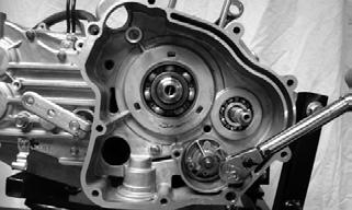
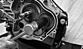
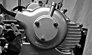
A.Rotor/Flywheel B.Stator Coil/Signal Coil C.Trigger Coil D.Starter One-Way Clutch E.Starter Gears F.Oil Pump/Oil Pump Drive G.Countershaft Drive Gear H.Crankshaft Gear 1.Remove the magneto cover noting the location of one short cap screw. Account for a gasket, oil through, and two alignment pins.

TR089A
TR150
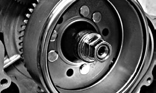
2.Remove the rotor/flywheel nut. Account for a flat washer.
3.Using the appropriate rotor/flywheel puller, remove the rotor/flywheel. Account for the key.

TR090
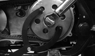
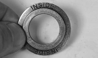
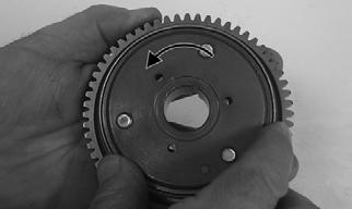
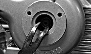
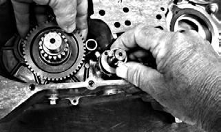
4.Using a spanner wrench or appropriate socket, remove the nut (left-hand thread) securing the starter gear and starter one-way clutch assembly to the crankshaft. Account for stepped washer noting that the word INSIDE is directed toward the clutch assembly.
TR191A
TR144
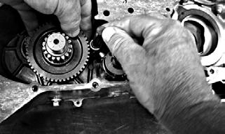
5.Remove the starter gear/starter one-way clutch assembly. Account for a key and stepped washer noting that the word INSIDE is directed toward the crankcase and the washer has a keyway.
TR167A

TR096
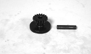
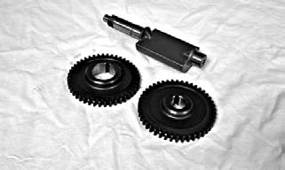
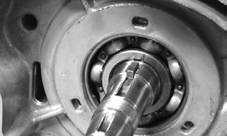
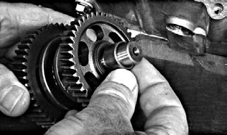
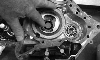
6.Remove the starter countershaft gears; then remove the countershaft.
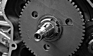
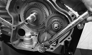
7.Remove the balancer shaft drive gear nut (left-hand thread). Account for a stepped washer with the stepped side directed toward the drive gear.

TR094
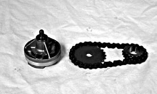
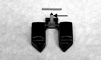
8.Remove the oil pump driven gear nut; then remove the oil pump drive gear, drive chain, and driven gear.
Account for a key and spacer.

TR095
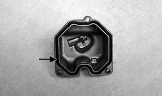
9.Remove the two oil pump mounting cap screws; then remove the oil pump assembly noting the directional arrow.
TR104
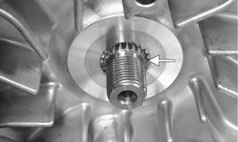
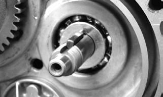
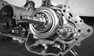
10.Remove the crankshaft drive gear. Account for a key.

TR100

TR099
NOTE: The crankshaft gear is not a press-fit gear
and can be removed by hand.
Servicing Right-Side Components
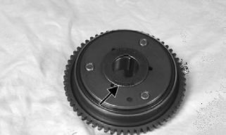
INSPECTING 1.Inspect wires, wire routing, and grommets in the magneto cover. 2.Inspect starter gears, starter one-way clutch, and starter countershaft and gears. Confirm that starter one-way clutch only turns one direction.
TR154
TR149A
3.Check all keys for signs of shearing or chaffing. 4.Inspect the oil pump drive sprockets, chain, and oil pump assembly for excessive wear, discoloration, or oil pump binding internally.
TR170
5.Inspect the crankshaft drive gear, balancer shaft drive gear, and keyways for wear, chipping, or discoloration.
TR168
6.Look for any signs of metal particles on the rotor/flywheel which might indicate internal parts failure.
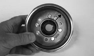
TR147A
7.Inspect the rotor/flywheel for cracks, loose rivets, or worn keyway.

TR146A
Installing Right-Side Components
NOTE: When assembling components, always use
new gaskets, O-rings, and seals. Coat all moving parts with fresh, clean engine oil.
1.Install the oil pump assembly into the crankcase making sure the arrow is directed upward; then secure with the two cap screws and tighten to 7 ft-lb.

TR104A
TR182
2.Install a square key into the crankshaft; then install the crankshaft drive gear onto the crankshaft.
TR183

TR184
3.Install a spacer and square key on the balancer shaft; then align the timing mark on the balancer driven gear to the timing mark on the drive gear and slide the driven gear into place.
TR185

TR186
4.Install the oil pump drive gear, chain, and driven gear as an assembly; then apply red Loctite #271 to the oil pump shaft and secure with oil pump driven gear nut.
Tighten to 7 ft-lb.
TR188
5.Install the washer with the word INSIDE toward the gear; then apply red Loctite #271 to the threads and install the balancer nut (left-hand thread). Tighten to 32 ft-lb.
TR189
6.Install the starter drive countershaft and countershaft gears.

TR190A
7.Install the inner starter one-way drive washer with the word INSIDE directed toward the crankshaft drive gear; then install a key and the starter one-way drive assembly.
TR096

TR190B
8.Install the outer starter one-way drive washer with the word INSIDE directed toward the starter oneway drive assembly; then coat the crankshaft threads with red Loctite #271 and secure with the nut (lefthand thread). Tighten to 68 ft-lb.
TR144
TR191A
9.Install the oil pump baffle and secure with two cap screws. Tighten to 7 ft-lb.

TR193
10.Install the starter motor (if removed) and tighten the mounting screws to 7 ft-lb. 11.Install a key in the crankshaft; then install the rotor/ flywheel and flat washer and secure with the rotor/ flywheel nut. Tighten to 40 ft-lb.
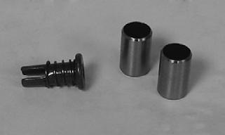
TR192
12.Place the two alignment pins and a new gasket onto the crankcase; then install the magneto cover assembly and secure with the cap screws. Tighten in a crisscross pattern to 7 ft-lb. NOTE: Account for the position of the short cap
screw.

TR196A
13.Place the oil through into the end of the crankshaft; then install the magneto cover and secure with three cap screws. Tighten to 7 ft-lb.

TR047 TR197
TR198
NOTE: The cover can only be installed one way as
the holes are drilled off-set.
Disassembling Crankcase Half
A. Crankshaft B. Crankshaft Balancer Shaft C. Timing Chain D. Secondary Transmission NOTE: Prior to disassembling the crankcase, the
left-side, right-side, and top-side components must be removed.
1.Make match marks on the shift lever and shaft; then remove the cap screw and remove the shift arm.

TR107
2.Remove the starter motor. Account for two cap screws and one O-ring.
3.Remove nine right-side cap screws and one left-side cap screw securing the crankcase halves together; then using a plastic mallet, tap the right-side case from the left-side case leaving all components in the left-side case. Account for two alignment pins and a gasket.

TR115
4.Remove the balancer shaft; then remove the crankshaft assembly and camshaft drive chain.

TR112

TR113
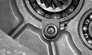
5.Remove the shift detent bolt, spring, and detent ball.
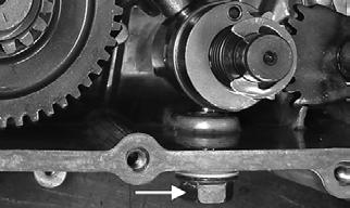
TR116A
NOTE: For steps 6-9, use photo TR115A. 6.Remove the shift shaft (A); then remove the shift fork shaft (B) and holding the shift fork away from the shift cam (C), remove the shift cam.
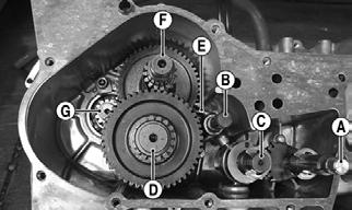
TR115A
7.Remove the main shaft assembly (D) along with the shift fork (E). Account for a spacer and washer. 8.Remove the countershaft (F). 9.Remove two cap screws securing the bearing retainers to the crankcase; then using a press or plastic mallet, remove the driveshaft assembly (G) from the crankcase.
TR120A
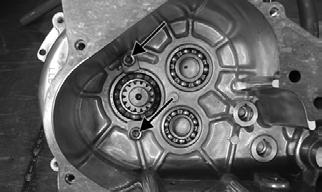
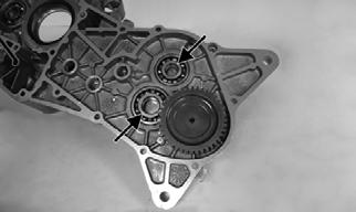
10.Using the appropriate bearing puller or driver, remove the required bearings from the crankcase halves.
Servicing Center Crankcase Components
To disassemble the main shaft, use the following procedure.
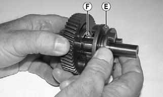
1.Remove the spacer (A), washer (B), forward gear (C), and forward gear bushing (D).

TR130A
2.Remove the forward/reverse shift dog (E); then remove the snap ring (F).
TR133A
3.Remove the splined washer (G); then remove the reverse gear (I), reverse gear bearing (H), and thrust washer (J). The main shaft is now disassembled for inspection of components.
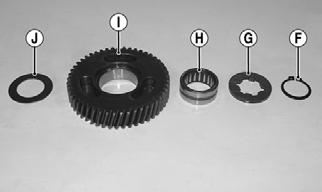
TR131A
INSPECTING 1.Inspect all gear teeth and shift dog lugs for excessive wear, chipping, or cracking.
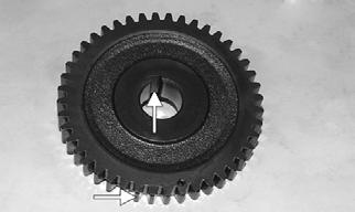
TR145A

TR142A
2.Inspect the transmission shafts, bushings, and bearings for excessive wear or discoloration. 3.Check splines for excessive wear or twisting.

TR162A
4.Check shift fork for excessive wear or discoloration.

TR153
5.Check shift fork shaft for distortion. Maximum distortion (runout) must not exceed specifications.

TR155
6.Inspect crankshaft bearings for smoothness of turning and any signs of discoloration.

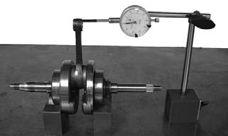
TR160
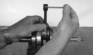
7.Using V-blocks and a dial gauge, check crankshaft runout. Maximum runout must not exceed specifications.

TR121
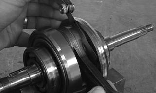
8.Check connecting rod small-end deflection. Maximum deflection must not exceed specifications. 9.Measure the connecting rod to crankshaft clearance using a thickness gauge. The measurement must not exceed specifications.
TR124
10.Using a snap gauge and micrometer, measure the connecting rod small-end inside diameter. The measurement must not exceed specifications.
TR128

TR129
11.Using an appropriate micrometer or caliper, measure the crankshaft web-to-web width. If the measurement exceeds specifications, the crankshaft must be repaired or replaced.

TR140
12.Check all case bearings for smoothness of rotation, tightness in case, and discoloration. If bearings are loose in the case or discolored, the crankcase assembly must be replaced.
TR159A
13.Inspect the shift cam for excessive wear or broken springs.

TR139
Assembling Crankcase Half
NOTE: Coat all bearings, shafts, gears, and seals
with gear lubricant when installing.
1.Coat the lips of the seal and bearings with gear oil; then using a press or suitable driver, install the driveshaft and bearing into the left-side crankcase half.

TR165
2.Coat the bearing retainer cap screw threads with blue
Loctite #242 and secure the bearing retainers.
Tighten securely.

TR164A
CAUTION
Make sure the bearing retainers are properly seated against the retainer stops or damage to the transmission will occur.
TR163A
3.Install the countershaft; then install the assembled main shaft into the case making sure the bushing and washer are in place on the main shaft.

TR175
TR176
4.Install the shift fork; then install the shift cam and shift fork shaft.
TR177
TR178
5.Install the shift shaft making sure the timing marks are matched.

TR179A
6.Install the timing chain into the case; then apply grease to the lips of the crankshaft seal and install the crankshaft.
TR180
NOTE: To simplify holding the timing chain in posi-
tion on the lower end, pack a small amount of all-purpose grease into the case and “stick” the chain in place.
7.Install the balancer shaft; then install the right-side crankcase half with a new gasket.
TR181
8.Lightly tap the case halves together until fully seated; then secure with nine right-side cap screws and one left-side cap screw.

TR108A
TR110A
CAUTION
Do not draw the case halves together with the crankcase cap screws. Damage to the case may occur.
9.Tighten the cap screws (from step 8) in a crisscross pattern to 7 ft-lb. 10.Install the shift detent ball, spring, and shift detent bolt. Tighten to 35 ft-lb.

TR109A
11.Install the shift lever aligning the match marks; then install the cap screw and tighten securely.
TR107A
Installing Engine/ Transmission
1.From the left side of the frame, install the engine/ transmission assembly. 2.Install the left front engine mounting bracket onto the frame and tighten the cap screws to 29 ft-lb; then install the three through-bolts and nuts and tighten to 29 ft-lb.
3.Install the drive sprocket, retainer, and retainer cap screws. Tighten to 40 ft-lb. Install the drive sprocket guard.
TR075A
NOTE: If the drive chain was loosened to remove
the sprocket, adjust drive chain (see Periodic Maintenance/Tune-Up — Drive Chain).
4.Using a new GRAFOIL gasket, install the exhaust pipe/muffler assembly and loosely secure with the mounting cap screws.
TR062A
TR073A
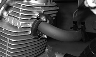
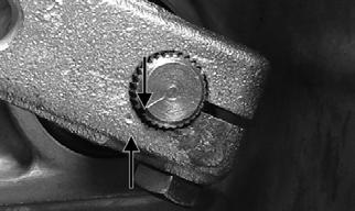
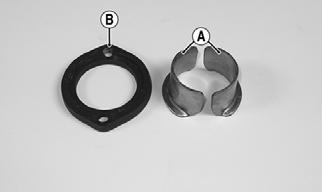
5.Place the two sealing wedges (A) into the cylinder head and secure with the exhaust flange (B). Secure with the two nuts and tighten to 25 ft-lb.
TR041A
TR067A
6.Connect the gear position switch, trigger coil, and signal coil connectors.
TR070A
7.Install the CVT cooling ducts making sure to align the notches in the boots with the location lugs.
Tighten the clamps securely.

TR063A

TR061A
8.Connect the AC generator plug; then install a cable tie at marked location.
TR072A
9.From the right-side, connect the shift rod to the lower shift arm, then connect the starter lead and install the spark plug cap.
TR059A
10.Install the carburetor assembly and secure the intake pipe to the cylinder with two nuts. Tighten securely.
TR058A TR049
12.Install the gas tank (see Fuel/Lubrication/Coolingsection); then install the left-side and right-side footwells and side covers.

13.Connect the battery and install the seat. 14.Pour in the proper quantities of engine/transmission oil; then start the engine and warm up to operating temperature. 15.Check for leaks; then shut off engine and check levels.
Fuel/Lubrication/ Cooling
Carburetor
! WARNING
Whenever any maintenance or inspection is performed on the fuel system during which there may be fuel leakage, there should be no welding, smoking, open flames, etc., in the area.
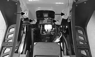
REMOVING 1.Remove the seat; then remove the left-side heat shield and turn the gas tank shut-off valve to the OFF position. 2.Remove the cap screws securing the air filter housing to the frame; then loosen the clamp securing air inlet boot to the carburetor and remove the air filter.
TR022B
3.Remove the choke assembly from the carburetor leaving the choke cable attached to the choke plunger. 4.Loosen the screw securing the choke cable to the carburetor; then disconnect the choke cable. 5.Remove the nuts securing the carburetor to the intake pipe; then remove the carburetor from the intake pipe. 6.Remove the fuel hose from the carburetor.
7.Remove the throttle valve cap and throttle cable/ throttle valve from the carburetor and remove the carburetor from the ATV. Secure the cable and throttle valve so the valve and needle will not be damaged.
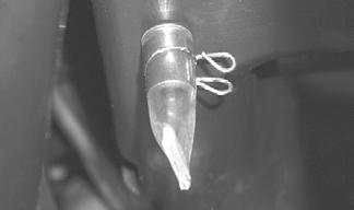
DISASSEMBLING 1.Remove the Phillips-head screws securing the float chamber; then remove the chamber. Account for the
O-ring.

TR203A
TR204A
2.Remove the float pin.

TR207
3.Lift the float assembly from the carburetor. Account for the float valve.
TR206A
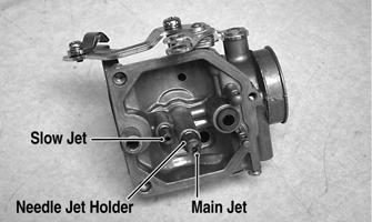
NOTE: Note the locations of the jets and holder for