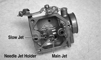
9. Inspect the slow jet and main jet for obstructions or damage. NOTE: If the slow jet is obstructed, the mixture will be extremely lean at idle and part-throttle operation.
10. Inspect the float valve for wear or damage. 11. Inspect the carburetor mounting flange for damage and tightness. ASSEMBLING NOTE: Note the locations of the jets and holder during assembling procedures. TR207B
4. Secure the needle jet holder with a wrench; then remove the main jet.
TR207B
1. Install the slow jet. Tighten securely. KC0030A
5. Remove the needle jet holder; then remove the slow jet. CLEANING AND INSPECTING.
2. Install the main jet into the needle jet holder and tighten securely; then install the needle jet holder assembly into the carburetor and tighten securely. 3. Place the float assembly (with float valve) into position and secure to the carburetor with the float pin.
! WARNING When drying components with compressed air, always wear safety glasses.
CAUTION DO NOT place any non-metallic components in partscleaning solvent because damage or deterioration will result.
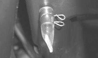
1. Place all metallic components in a wire basket and submerge in carburetor cleaner. 2. Soak for 30 minutes; then rinse with clean, hot water. 3. Wash all non-metallic components with soap and water. Rinse thoroughly. 4. Dry all components with compressed air only making sure all holes, orifices, and channels are unobstructed. 5. Inspect the carburetor body for cracks, nicks, stripped threads, and any imperfections in the casting.
TR205A
NOTE: Check float arm height by placing the carburetor on its side w/float contacting the needle; then measure with a caliper the height when the float arm is in contact with the needle valve. Float arm height should be 14.8 mm.
6. Inspect float for damage. 7. Inspect gasket and O-rings for distortion, tears, or noticeable damage. 8. Inspect tips of the jet needle and the needle jet for wear, damage, or distortion.
59