HIERARCHY
2
3 4
1
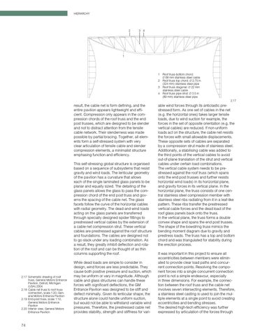
1 Roof truss bottom chord: Ø 88 mm stainless steel cable 2 Roof truss top chord: Ø 2.75 in (324 mm) stainless steel pipe 3 Roof truss diagonal: Ø 22 mm stainless steel cable 4 Roof truss pipe strut: Ø 3.5 in (89 mm) stainless steel pipe 2.17
result, the cable net is form defining, and the entire pavilion appears lightweight and effi cient. Compression only appears in the com pression chords of the roof truss and the end post trusses, which are designed to be slender and not to distract attention from the tensile cable network. Their slenderness was made possible by partial bracing. Together, all elem ents form a self-stressed system with very clear articulation of tensile cable and slender compression elements, a minimalist structure emphasing function and efficiency. This self-stressing global structure is organised based on a sequence of subsystems that resist gravity and wind loads. The lenticular geometry of the pavilion has a curvature that allows each of the single laminated glass panels to be planar and equally sized. The detailing of the glass panels allows the glass to pass the com pression chord of the end post truss and gov erns the spacing of the cable net. The glass facets follow the curve of the horizontal cables with radial geometry. The dead and wind loads acting on the glass panels are transferred through specially designed spider fittings to prestressed vertical cables by the extension of a cable net compression strut. These vertical cables are prestressed against the roof structure and foundations. The cables are designed not to go slack under any loading combination. As a result, they greatly inhibit deflection and rota tion of the roof and can be thought of as thin columns supporting the roof.
2.17 Schematic drawing of roof truss, General Motors Entrance Pavilion, Detroit, Michigan (USA) 2004 2.18 Cable net truss to roof truss connection, scale 1:20, Gen eral Motors Entrance Pavilion 2.19 End-post truss, scale 1:10, General Motors Entrance Pavilion 2.20 Interior view, General Motors Entrance Pavilion
74
While dead loads are simple to consider in design, wind forces are less predictable. They cause both positive pressure and suction, which may be uniform or vary in magnitude. Although cable and glass structures can handle these forces with significant deflections, the GM Entrance Pavilion was designed to be stiff and deflect minimally. Given its lenticular shape, the structure alone could handle uniform suction, but would not be able to withstand variable wind pressures. Therefore, the prestressed cable net provides stability, strength and stiffness for vari
able wind forces through its anticlastic pre stressed form. As one set of cables in the net (e.g. the horizontal ones) takes larger tensile loads, due to wind suction for example, the forces in the set of opposite orientation (e.g. the vertical cables) are reduced. If non-uniform loads act on the structure, the cable net resists the forces with small allowable displacements. These opposite sets of cables are separated by a compression strut made of stainless steel. Additionally, a stabilising cable was added to the third points of the vertical cables to avoid out-of-plane translation of the strut and vertical cables under certain load combinations. The vertical cable system needs to be pre stressed against the roof truss (which spans onto the end post trusses and further resists horizontal wind loads) in its horizontal plane, and gravity forces in its vertical plane. In the horizontal plane, the truss consists of one cen tral stainless steel compression member with stainless steel ribs radiating from it in a leaf-like pattern. These ribs transfer the prestressed vertical cable forces and the dead load of the roof glass panels back onto the truss. In the vertical plane, the truss forms a double convex shape and spans the end post trusses. The shape of the bowstring truss mimics the bending moment diagram due to gravity and prestress loads. The truss has a top and bottom chord and was triangulated for stability during the erection process. It was important in this project to ensure all eccentricities between members were elimin ated to provide clear load paths and concur rent connection points. Resolving the compo nent forces into a single concurrent connection point is not a simple endeavour, especially in three dimensions. For example, the connec tion between the roof truss and the cable net involves seven intersecting elements. Therefore, a stainless steel casting is used to join the mul tiple elements at a single point to avoid creating eccentricities and bending stresses. The desired high-tech efficiency was further expressed by articulation of the forces through
