Structure as poetry
1 2
3-dimensional cable net End post truss 3 5
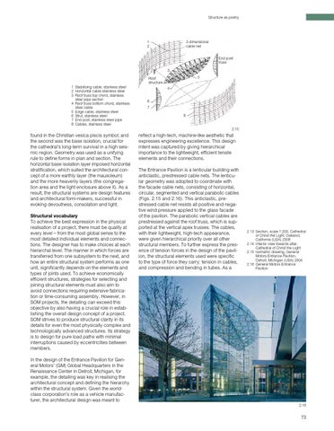
Roof structure 1 Stabilising cable, stainless steel 2 Horizontal cable stainless steel 3 Roof truss top chord, stainless steel pipe section 4 Roof truss bottom chord, stainless steel cable 5 Edge cable, stainless steel 6 Strut, stainless steel 7 End post, stainless steel pipe 8 Cables, stainless steel
4 6 7 8
2.15
found in the Christian vesica piscis symbol; and the second was the base isolation, crucial for the cathedral’s long-term survival in a high seis mic region. Geometry was used as a unifying rule to define forms in plan and section. The horizontal base isolation layer imposed horizontal stratification, which suited the architectural con cept of a more earthly layer (the mausoleum) and the more heavenly layers (the congrega tion area and the light enclosure above it). As a result, the structural systems are design features and architectural form-makers, successful in evoking devoutness, consolation and light. Structural vocabulary To achieve the best expression in the physical realisation of a project, there must be quality at every level – from the most global sense to the most detailed individual elements and connec tions. The designer has to make choices at each hierarchal level. The manner in which forces are transferred from one subsystem to the next, and how an entire structural system performs as one unit, significantly depends on the elements and types of joints used. To achieve economically efficient structures, strategies for selecting and joining structural elements must also aim to avoid connections requiring extensive fabrica tion or time-consuming assembly. However, in SOM projects, the detailing can exceed this objective by also having a crucial role in estab lishing the overall design concept of a project. SOM strives to produce structural clarity in its details for even the most physically complex and technologically advanced structures. Its strategy is to design for pure load paths with minimal interruptions caused by eccentricities between members.
reflect a high-tech, machine-like aesthetic that expresses engineering excellence. This design intent was captured by giving hierarchical importance to the lightweight, efficient tensile elements and their connections. The Entrance Pavilion is a lenticular building with anticlastic, prestressed cable nets. The lenticu lar geometry was adopted to coordinate with the facade cable nets, consisting of horizontal, circular, segmented and vertical parabolic cables (Figs. 2.15 and 2.16). This anticlastic, pre stressed cable net resists all positive and nega tive wind pressure applied to the glass facade of the pavilion. The parabolic vertical cables are prestressed against the roof truss, which is sup ported at the vertical apex trusses. The cables, with their lightweight, high-tech appearance, were given hierarchical priority over all other structural members. To further express the pres ence of tension forces in the design of the pavil ion, the structural elements used were specific to the type of force they carry: tension in cables, and compression and bending in tubes. As a
2.13 Section, scale 1:200, Cathedral of Christ the Light, Oakland, California (USA) 2008 2.14 Interior view towards altar, Cathedral of Christ the Light 2.15 Isometric drawing, General Motors Entrance Pavilion, Detroit, Michigan (USA) 2004 2.16 General Motors Entrance Pavilion
In the design of the Entrance Pavilion for Gen eral Motors’ (GM) Global Headquarters in the Renaissance Center in Detroit, Michigan, for example, the detailing was key in realising the architectural concept and defining the hierarchy within the structural system. Given the worldclass corporation’s role as a vehicle manufac turer, the architectural design was meant to 2.16
73