Service Information
Construction Equipment

Document Title: Function Group: Information Type: Service Information Date: 25/01/2012
Profile: EXC, EC330B LC (Volvo) [GB]
General precautions
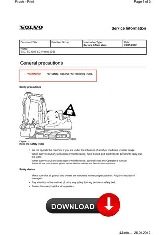
t WARNlNs! For safety, observe the following rules.
Safety precautions
• Do not operate the machine if you are under the influence of alcohol, medicine or other drugs. When carrying out any operation or maintenance, have trained and experienced personnel carry out the work.

When carrying out any operation or maintenance, carefully read the Operator's manual. Read all the precautions given on the decals which are fixed to the machine.
Safety device
Make sure that all guards and covers are mounted in their proper position. Repair or replace if damaged.
• Pay attention to the method of using any safety locking device or safety belt.
• Fasten the safety belt for all operations.
Safety clothes and hard hat
Wear clothes suitable for welding work


• Wear the specified work clothes in the correct manner. Use the specified protective gear (hard hat, safety glasses, safety shoes, mask, gloves). Guard against injury from flying pieces of metal or debris, wear goggles, gloves and helmet. Always have a trained and experienced welder carry out any welding work. When carrying out welding work, always wear welding gloves, apron, glasses, cap and other clothes suitable for welding work.
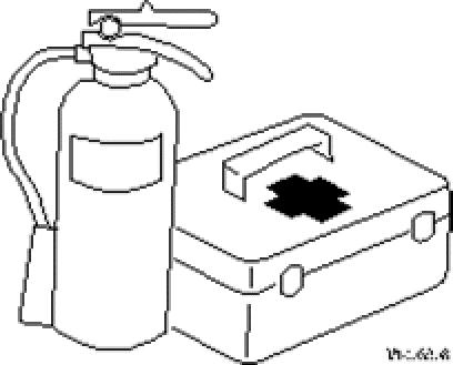
Prepare for emergencies
Prepare for emergencies
• Know where fire extinguishers are located and how to use them.


• Keep a first aid kit and an eye wash kit near the work area. Keep emergency numbers for doctors, ambulance service, hospital, and fire department near your telephone.
Handle fluids safely-avoid fires
Avoid fires
• HandIe fuel with care. It is highly flammable. Do not refuel the machine while smoking or when near open flame or sparks. Always stop the engine before refuelling machine. Fill the fuel tank outdoors.
Store flammable fluids away from fire hazards. Do not incinerate or puncture pressurized containers.


Dispose of fluids properly
Do not pour oil into the ground
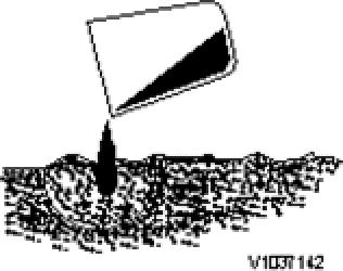
Improperly disposing of fluids can harm the environment and ecology. Before draining any fluids, find out the proper way to dispose of waste from your local environmental agency. Catch draining fuel, oil, or other fluids in suitable containers. Do not use food or beverage containers that may mislead someone into drinking from them. Wipe up spills at once.
Do not pour oil into the ground, down a drain, or into a stream, pond, or lake. Observe relevant environmental protection regulations when disposing of oil, fuel, coolant, filters, batteries, and other harmful waste.
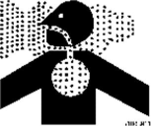
Working in contaminated environment
Avoid breathing dust
Used cab and engine air filters from machines which operate in environments containing asbestos or other dangerous dust must be placed in the tight-fitting bag, before they are deposited in a designated place.
The machine must be equipped for work within an environment which is contaminated or constitutes a health hazard before the work is initiated. Besides, special local regulations apply for such operations and for servicing a machine which has been used in such environment.
Crystalline silica (quartz) dust
Because crystalline silica is a basis component of sand and granite, many activities at construction sites produce dust containing crystalline silica. Trenching, sawing and boring of material containing crystalline silica can produce dust containing crystalline silica. If dust which contains crystalline silica is present there are guidelines which should be followed.
1. Be aware of the health effects of crystalline silica and that smoking adds to the damage.
2. Be aware of and follows OSHA (or other) guidelines for exposure to airborne crystalline silica.
3. Know the work operations where exposure to crystalline silica may occur.
4. Participate in air monitoring or training programs offered by the employer.
5. Be aware of and use optional equipment controls such as water sprays, local exhaust ventilation, and enclosed cabs with positive pressure air conditioning.
6. Where respirators are required, wear a respirator approved for protection against crystalline silicacontaining dust. Do not alter the respirator in any way. Workers who use tight-fitting respirators cannot have beards/mustaches which interfere with the respirator seal to the face.
7. If possible, change into disposable or washable work clothes at the work site ; shower and change into clean clothing before leaving the work site.
8. Do not eat, drink use tobacco products, or apply cosmetics in areas where there is dust containing crystalline silica.
9. Store food, drink and personal belongings away from the work area.
10. Wash hands and face before eating, drinking, smoking, or applying cosmetics after leaving the exposure area.
Document Title: Function Group: Information Type: Service Inform ation Date: 25/01/2012
Profile:
EXC, EC330B LC (Volvo) [GB]
Preparations for work
Warn others of service work

Sound
• Unexpected machine movement can cause serious injury.
• Before performing any work on the machine, attach a warning tag on the remote control lever. When carrying out any operation with two or more workers, always agree on the operating procedure before starting.

Turn on the travel alarm off switch when you start to move the machine.. Sound the horn and let other workers and bystanders know you are starting the machine.
Hot filament of a broken bulb can ignite spilled fuel or oil
IIluminate your work area adequately but safely. Use a portable safety light for working inside or under the machine. Make sure the bulb is enclosed by a wire cage.
The hot filament of an accidentally broken bulb can ignite spilled fuel or oil.
Use tools safely
• Use a tool only for its designed application.
• Keep all tools in good condition and know the correct way to use them.
• Decide on a place in the repair workshop to keep tools and removed parts.
• Always keep the work area clean and make sure that there is no dirt or oil on the floor.
Before adding oil or making any repairs, park the machine on hard, level ground and put blocks under the wheels or tracks to prevent the machine from moving.
Before starting work, lower the blade, ripper, bucket or any other work equipment to the ground. If that is not possible, insert the safety pin or use blocks to prevent the work equipment from falling.

Control lockout system
Place the control lockout lever securely to "Locked" position to lock out the WARNING! control hydraulics before starting the engine or leaving the operator's seat. Unless the control lockout lever is in the "Locked" position, control levers can be operated by careless touch, which could cause serious injury.
Control lockout system
A. Unlocked position (When this lever is put at this position the engine can not be started)

B. Locked position (When this lever is put at this position the engine can be started)

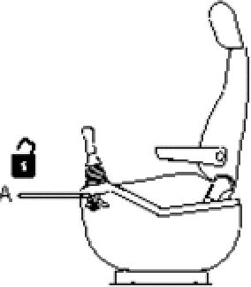
1. control lockout lever
2. Control lever (left)
3. Left control console
4. Backrest
Use handholds and steps
Never jump on/off the machine
• Never jump on or off the machine
Always maintain a three point contact with the steps and handrails
When you get on and off the machine, always maintain a three point contact (two feet and one hand or one foot and two hands) with the steps and handrails and face the machine. Do not use any controls as handholds, when entering or leaving the operator's station. Do not try to climb on or off the machine when carrying tools or supplies. Use a hand line to pull equipment up onto the platform.


Remove all mud and oil from the steps
• Remove all mud and oil from the steps of other places used to get on and off the machine.
Cautions during operation


Service cooling system safely
Hot coolant can burn you
At operating temperature, the engine coolant is hot and under pressure. The radiator and all lines to the heaters and engine contain hot coolant. Any contact can cause severe burns.
• Hot coolant can cause personal injury.

Check the coolant level only after the engine has been stopped and the radiator pressure cap is cool enough to remove with your bare hand.
• Remove the radiator pressure cap slowly to release pressure. Cooling system additive contains alkali that can cause personal injury. Avoid contact with the skin, eyes and mouth.
• Allow cooling system components to cool before draining.

Avoid high-pressure fluids
Avoid high pressure fluids
• Escaping fluid under pressure can penetrate the skin causing serious injury. Avoid the hazard by releasing pressure before disconnecting hydraulic or other lines. Tighten all connections before applying pressure.
Cautions during operation
Service cooling system safely
Hot coolant can burn you
At operating temperature, the engine coolant is hot and under pressure. The radiator and all lines to the heaters and engine contain hot coolant. Any contact can cause severe burns.
• Hot coolant can cause personal injury.
Check the coolant level only after the engine has been stopped and the radiator pressure cap is cool enough to remove with your bare hand.
• Remove the radiator pressure cap slowly to release pressure. Cooling system additive contains alkali that can cause personal injury. Avoid contact with the skin, eyes and mouth.
• Allow cooling system components to cool before draining.
Avoid high-pressure fluids
Avoid high pressure fluids
• Escaping fluid under pressure can penetrate the skin causing serious injury. Avoid the hazard by releasing pressure before disconnecting hydraulic or other lines. Tighten all connections before applying pressure.
Fluid leaks under pressure may not be visible. Use a piece of cardboard or wood to find leaks but do not use your bare hand. Protect hands and body from high pressure fluids.
Be careful not to break, twist or damage the high pressure pipes. A jet spray of high pressure oil can cause electrical fires.
Handling of heavy objects
Support the equipment safety
• When raising heavy components, use a hoist or crane.
• Ensure that wire ropes, chains and hooks are free from damage. Always use lifting equipment which has ample capacity. Install the lifting equipment at the correct places.
• Use a hoist or crane and operate slowly to prevent the component hitting any other part. When disassembling or assembling, support the machine with blocks, jacks or stands before starting work.

Never use concrete blocks for supports. They can collapse under even light loads.
• Before starting work, lower the blade, ripper, bucket or any other work equipment to the ground.
• Do not work under the equipment when the equipment is not sufficiently supported.

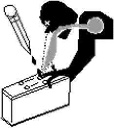
Electrical system
ALWAYS turn the master switch OFF when welding on the machine.
When working on the electrical system, ALWAYS turn the master switch OFF or remove the lead from the battery negative ( ) terminal.
• The battery master switch is installed inside the tool box located on the right side of machine.
When removing components, be careful not to break or damage the wiring.
Damaged wiring can cause electrical fires
° ON position (1)
Turn the key clockwise to supply power to the electrical system.
° OFF position (2)
Turn the key counter-clockwise to cut off electric power to the machine.
Electric welding
Before electric welding is carried out on the machine or any attachment installed to the machine, the current must be turned OFF at the battery master switch.
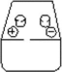
When working on the battery, pay attention
Before carrying out any electric welding on the machine, the battery cables should be disconnected and the connectors pulled out of the electronic control units.
When disconnecting and reconnecting, the leads should be without current (the battery master switch turned off).
• Connect the earth (ground) lead of the welding equipment as close to the welding point as possible. Before welding, remove all paint from an area of at least 10 cm (4 inch) around the point of welding. Paint which is heated gives off unhealthy gases.
All paint decomposes when heated and forms a great number of compounds, which may cause irritation and be dangerous to ones health after repeated or prolonged exposure.
In addition to the health hazard, the weld will be of inferior quality and strength, which, in the future, may cause the weld to break. Therefore, never weld directly on a painted surface.

• When working on the battery, wear goggles or safety glasses. Sulfuric acid in battery electrolyte is poisonous.
It is strong enough to burn skin and eat holes in clothing and cause blindness if splashed into the eyes. If you spill acid on your clothes or skin, immediately flush with large quantities of clean water, then get medical attention.
• If splashed into the eyes, flush with water and get medical attention immediately.

• Keep sparks, lighted matches, and open flame away from the top of battery. Battery (hydrogen) gas can explode.


• Battery posts and cables touched by metal objects can short circuit and burn you.
• Keep tools away from posts, wires and terminals.

• Tighten the battery terminals to ensure good contact.
When disassembling and assembling the battery, make sure that the battery terminals are correctly connected.
If water gets to the electrical system, abnormal operation or failure can result. Do not use water or steam on sensors, connectors and instruments in the cab.
Cautions during operation
Figure 8
Be careful when opening the grease valve
When removing covers which are under internal pressure or under pressure from a spring, always leave two screws in position on opposite sides. Slowly release the pressure, then slowly loosen the screws.
High pressure grease in the spring package of the undercarriage can explode and injure you.
Be careful when opening the grease valve.
Do not loosen the grease valve more than 1 turn until the pressure is released.
• When assembling or installing parts, always use the specified tightening torque.
When installing protective parts such as guards, or parts which rotate at high speed, be particularIy careful to check if they are installed correctly.
Figure 9
Do not contact rotating parts
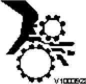
• Be sure that your clothes or hair do not contact any rotating components
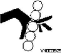
Figure 10
Be careful of your finger (1)
When aligning two holes, never insert your fingers or hand. Be careful not to get your fingers pinched in a hole, or between parts or tools
Figure 11
Be careful of your finger (2)
Figure 12
Never touch rotating parts
• Never touch rotating parts such as the fan blades or fan belt.

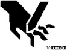
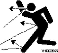
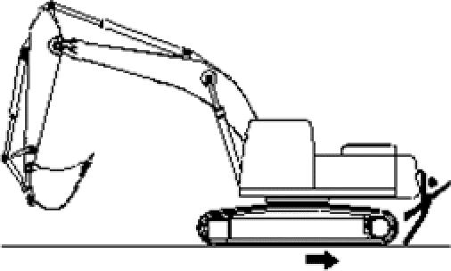
Figure 13
Pay attention when removing or installing the tracks
Pay attention when removing or installing the tracks of track type machines. When removing the track pin, the track separates suddenly, so never let anyone stand at either end of the track. Always block both ends of the track to prevent any sudden uncontrolled movement.

Document Title: Function Group: Information Type: Service Information Date: 25/01/2012
Profile: EXC, EC330B LC (Volvo) [GB]
Move and operate machine safely

Before moving, slewing or operating the machine check that the area is clear
Only allow the operator on the machine. Keep all riders off. Know the location of bystanders before moving, slewing or operating the machine.
Don't contact electric power lines
• Always keep the travel alarm in working condition.
• Use a signal person when moving, slew or operating the machine in a congested area. Before traveling check the traveling direction. ParticularIy, for reverse traveling, check that no person is in the area after slew to the rear side. Use the travel alarm before traveling.
Serious injury or death can result from contact with electric power lines. Never move any part of the machine or load closer to the electric power line than the minimum established safe distance.

• Refer to the Operator's manual for further details. Transporting the machine
NOTE NOTE
Loading, positioning, slinging and securing for transporting the machine on a trailer or other vehicle should be comply with the local or national laws and regulations.
The operator performing any work for transportation must be familiar with and be understood both operating information and related laws.
Please contact authorized personnel or Volvo CE dealer for any information that you NOTE may require.
Refer to the Operator's manual for further details (Transporting the machine).
Profile:
EXC, EC330B LC (Volvo) [GB]
Safety when handling the waste handler
Follow the safety rules in the standard Operator's Manual for the respective machines before carrying out any operation, service and maintenance. For service work high up on the machine, always use footsteps and stepping surfaces intended for this purpose.
It is important that waste, which accumulated inside guard plates, covers and by cylinders, is removed daily in order to avoid fire hazards. Also make sure that waste, which has accumulated around the engine, is removed and check that there are no fuel NOTE or oil leaks. At the slightest sign of a leak remedial action must be taken immediately. When operating in an area which is contaminated or dangerous to one's health, the machine must be especially equipped for the exact purpose. Specific local safety regulations apply within such areas and also when servicing the machine.
High-pressure wash
If high-pressure wash is used for cleaning, make sure not to direct the water jet against electrical cables and electrical components. Even at reduced pressure and temperature the insulation on the cables may be damaged. Correct distance and constant movement of the nozzle will reduce the risk of damage.
Spring loaded items
If disassembly of the spring-loaded items is required, take caution to ensure that you are well protected from the load release which may be sudden and pose an impact related injury threat.
Hot
fluids and parts
To avoid burns, be alert for hot parts on the assembly for a machine that has just been stopped and has fluids in lines, tubes and compartments. Be careful when removing fill plugs and other components on the fan assembly. Hold a rag over the plug to prevent being sprayed or splashed by liquids which may be under pressure. Always wear the appropriate protective equipment when dealing with hot fluids and parts.
Service and cleaning
Damage to the waste handler caused by the waste must be prevented, while at the same time all important functions and components must be accessible for service and maintenance. Therefore, the machine is equipped with a fan, guard plates and access covers in order to facilitate cleaning and service work as well as a fan.
In case of fire in the machine with fire suppression system
Extinguishing of flowing flammable liquid fires may result in a reflash unless all NOTE sources of ignition have been removed. Flammable gases present a potential explosion hazard if the flow of gas is not stopped before or during extinguishm ent.
Discharge of a fire suppression system is noisy and can produce a large cloud of NOTE extinguishing agent ternporarily obstructing vision. Breathing the extinguishing agent is unpleasant and may cause some irritation.
NOTE
Don't restart the machine until it has been serviced and cleaned. Use a water stream or compressed air to remove dry chemical residue immediately to avoid corrosion. For further information about fire prevention measures, see the standard Operator's Manual.
Service
Construction Equipment
Document Title: Function Group: Information Type: Service Information
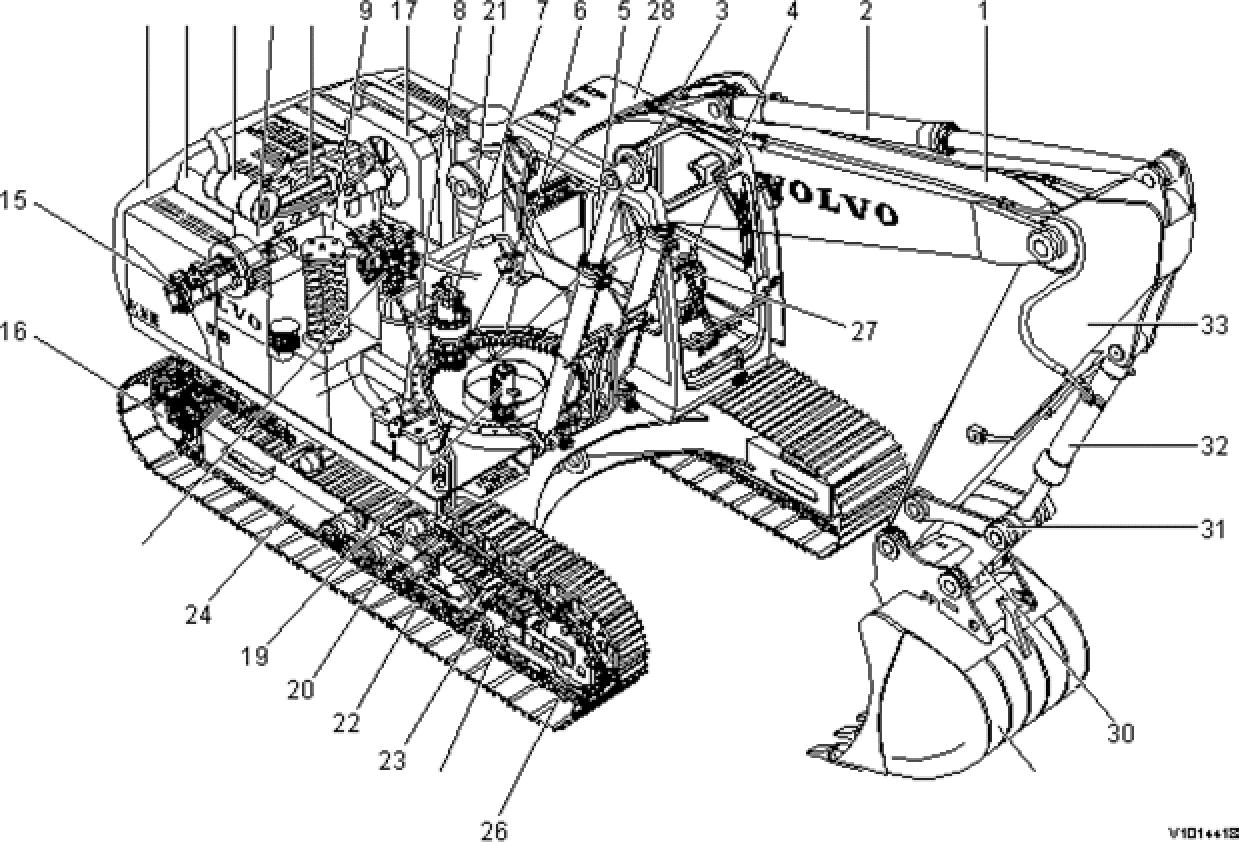
Component locations
27Control
29Bucket
33Arm


Standard tightening torques
The following charts give the standard tightening torques of screws and nuts. Exceptions are given in each sections of "disassembly and assembly”.


This torque table does not apply to screws with nylon packings or where nonferrous NOTE metal washers are to be used, or which require tightening to a different specified torque, or tightening procedure.
Tightening torque of split flange screws
Use these torques forsplit flange screws.
Tightening torque (split flange screws)
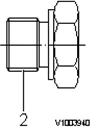
Tightening torque for hydraulic plugs with O-ring
Pf thread


Tightening torque (hydraulic plugs)
Tightening torque for swivel nut fitting with O-ring
Tightening torque for swivel nut fitting
Measurement conversion tables
NET 8940-00170

NET 8940-00200 Replace tool for the remote control valve joint


NET 8940-00210 Inspection tool for the engine speed control switch
NET 8940-00220 Inspection tool for the power shift valve

NET 8940-00240 Replace tool for the hydraulic tee fitting


