John Deere 430 Lawn Garden Tractors Service Manual
Lawn and Garden Tractors
For complete service information also see:
Yanmar Gasoline Engines.
John Deere Series 220 Diesel Engines
CTM12
CTM3
FOREWORD
This manual is written for an experienced technician. Essential tools required in performing certain service work are identified in this manual and are recommended for use.
Live with safety: Read the safety messages in the introduction of this manual and the cautions presented throughout the text of the manual.
NThis is the safety-alert symbol. When you see this symbol on the machine or in this manual, be alert to the potential for personal injury.
Technical manuals are divided in two parts: repair and diagnostics. Repair sections tell how to repair the components. Diagnostic sections help you identify the majority of routine failures quickly.
Information is organized in groups for the various components requiring service instruction. At the beginning of each group are summary listings of all applicable essential tools, other materials needed to do the job and service parts kits.
Section 10, Group 15—Repair Specifications, consist of all applicable specifications, near tolerances and specific torque values for various components on each individual machine.
Section 10, Group 20—Test and Adjustment Specifications, consist of all applicable test and adjustment specifications for various systems for each individual machine.
Binders, binder labels, and tab sets can be ordered by John Deere dealers direct from the John Deere Distribution Service Center.
This manual is part of a total product support program.
FOS MANUALS—REFERENCE
TECHNICAL MANUALS—MACHINE SERVICE
COMPONENT MANUALS—COMPONENT SERVICE
Fundamentals of Service (FOS) Manuals cover basic theory of operation, fundamentals of troubleshooting, general maintenance, and basic type of failures and their causes. FOS Manuals are for training new personnel and for reference by experienced technicians.
Technical Manuals are concise guides for specific machines. Technical manuals are on-the-job guides containing only the vital information needed for diagnosis, analysis, testing, and repair.
Component Technical Manuals are concise service guides for specific components. Component technical manuals are written as stand-alone manuals covering multiple machine applications.
DOWNLOAD SERVICE MANUAL
SECTION 10—GENERAL INFORMATION
Group 05—Safety
Group 10—General Specifications
Group 15—Repair Specifications
Group 20—Test and Adjustment Specifications
Group 25—Fuels and Lubricants
Group 30—Serial Number Locations
SECTION 20—ENGINE REPAIR
Group 05—Engine—322
Group 06—Engine—330, 332 and 430
SECTION 40—ELECTRICAL REPAIR
Group 05—Front PTO Clutch
SECTION 50—POWER TRAIN REPAIR
Group 05—Transmission
Group 10—Transmission Control Linkage
Group 15—Differential
Group 20—Rear Axles
Group 25—Drive Shaft—322, 330 and 332
Group 26—Drive Shaft—430
SECTION 60—STEERING AND BRAKE REPAIR
Group 05—Steering—330
Group 06—Steering—322, 332 and 430
Group 10—Brakes
SECTION 70—HYDRAULIC REPAIR
Group 05—Hydraulic Control Valve
SECTION 80—MISCELLANEOUS REPAIR
Group 05—Front Axle
Group 10—Mower Spindle and Jack Sheave Repair
Group 15—Mower Gear Case Repair
SECTION 220—ENGINE, FUEL AND AIR SYSTEM CHECKOUT AND DIAGNOSIS
Group 05—Engine, Fuel and Air System Checkout
Group 10—Diagnosis, Tests and Adjustments—322
Group 11—Diagnosis, Tests and Adjustments—330, 332 and 430
SECTION 240—ELECTRICAL SYSTEM CHECKOUT, OPERATION AND DIAGNOSIS
Group 05—Electrical System Checkout
Group 10—Electrical Schematics
Group 15—Component Location and Operation
Group 20—Electrical System Diagnosis
Group 25—Electrical System Component Tests and Adjustments
SECTION 250—POWER TRAIN CHECKOUT, OPERATION AND DIAGNOSIS
Group 05—Power Train Checkout
Group 10—Theory of Operation
Group 15—Diagnosis, Tests and Adjustments
SECTION 260—STEERING AND BRAKES CHECKOUT, OPERATION AND DIAGNOSIS
Group 05—Steering And Brakes System Checkout
Group 10—Theory of Operation
Group 15—Diagnosis, Tests and Adjustments
SECTION 270—HYDRAULIC SYSTEM CHECKOUT, OPERATION AND DIAGNOSIS
Group 05—Hydraulic System Checkout
Group 10—Hydraulic Schematics
Group 15—Theory of Operation
Group 20—Diagnosis, Tests and Adjustments
SECTION 299—DEALER FABRICATED TOOLS
Group 00—Dealer Fabricated Tools
Index
All information, illustrations and specifications in this manual are based on the latest information available at the time of publication. The right is reserved to make changes at any time without notice. TM1591-19-15JUL95
Dealer Presentation Sheet
JOHN
DEERE DEALERS
IMPORTANT: Please remove this page and route through your service department.
This is a complete revision for models 322, 330, 332 and 430 found in TM1277, TM1309 and TM1345. The complete revision of remaining machines (316, 318 and 420) can be found in TM1590. AFTER recieving both TM1590 and TM1591, please discard old TM1277 dated December 1987, TM1309 dated July 1985 and TM1345 dated June 1986.
NOTE: There are several “versions” of each model tractor. All versions were not availble at time of latest printing. Some versions may not be covered.
Group 05—Safety
Group 10—General Specifications
Machine Specifications
322 and 330
Section 10
GENERAL INFORMATION
10-05-1
10-10-1
332 and 430 10-10-4
Group 15—Repair Specifications
Repair Specifications
10-15-1
Metric Series Torque Chart 10-15-4
Inch Series Torque Chart 10-15-5
Metric Torque Values—Grade 7 10-15-6
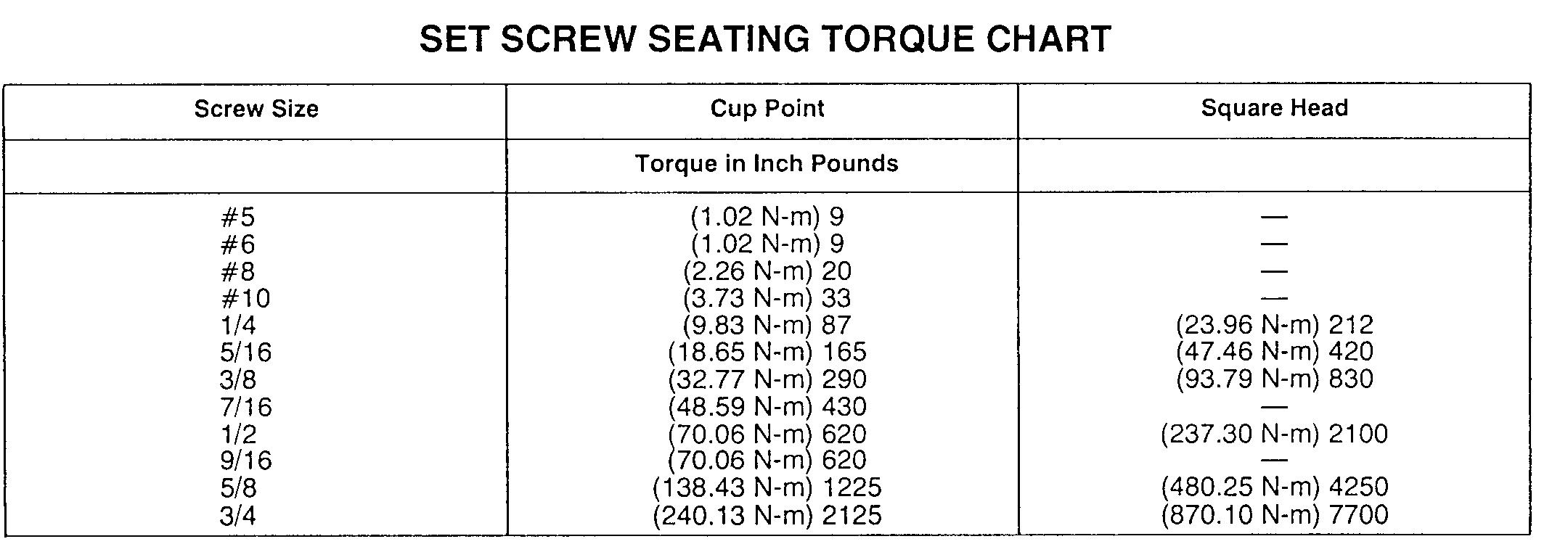
Set Screw Torque Chart .
Service Recommendations
. 10-15-6
Flat Face O-Ring Seal Fittings 10-15-8
Tube and Hose Fitting, 37˚ Flare and 30˚ Cone Seat Connectors 10-15-9
Group 20—Test and Adjustment Specifications
Group 25—Fuels and Lubricants
Fuel—322
10-20-1
10-25-1
Diesel Fuel—330, 332 and 430 10-25-2
Storing Fuel 10-25-3
Do Not Use Galvanized Containers
Engine Oil—322
10-25-3
10-25-4
Diesel Engine Oil—330, 332 and 430 10-25-5
Engine Coolant 10-25-6
Liquid Coolant Conditioner 10-25-6
Transmission and Hydraulic Oil 10-25-7
Grease 10-25-8
Mower Deck Gear Case Oil .
10-25-8
Alternative and Synthetic Lubricants 10-25-9
Lubricant Storage 10-25-9
Mixing of Lubricants 10-25-9
Group 30—Serial Number Locations
Serial Numbers Product Identification 10-30-1 Engine 10-30-1 Transmission
Differential
10-30-1
Control Valve 10-30-2
RECOGNIZE SAFETY INFORMATION
This is the safety-alert symbol. When you see this symbol on your machine or in this manual, be alert to the potential for personal injury.
Follow recommended precautions and safe operating practices.
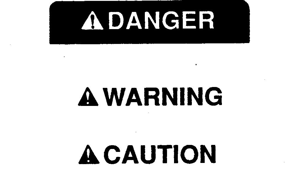
UNDERSTAND SIGNAL WORDS
A signal word—DANGER, WARNING, or CAUTION—is used with the safety-alert symbol. DANGER identifies the most serious hazards.
DANGER or WARNING safety signs are located near specific hazards. General precautions are listed on CAUTION safety signs. CAUTION also calls attention to safety messages in this manual.
FOLLOW SAFETY INSTRUCTIONS
Carefully read all safety messages in this manual and on your machine safety signs. Keep safety signs in good condition. Replace missing or damaged safety signs. Be sure new equipment components and repair parts include the current safety signs. Replacement safety signs are available from your John Deere dealer.
Learn how to operate the machine and how to use controls properly. Do not let anyone operate without instruction.
Keep your machine in proper working condition. Unauthorized modifications to the machine may impair the function and/or safety and affect machine life.
If you do not understand any part of this manual and need assistance, contact your John Deere dealer.
HANDLE FLUIDS SAFELY—AVOID FIRES
When you work around fuel, do not smoke or work near heaters or other fire hazards.
Store flammable fluids away from fire hazards. Do not incinerate or puncture pressurized containers.
Make sure machine is clean of trash, grease, and debris.
Do not store oily rags; they can ignite and burn spontaneously.
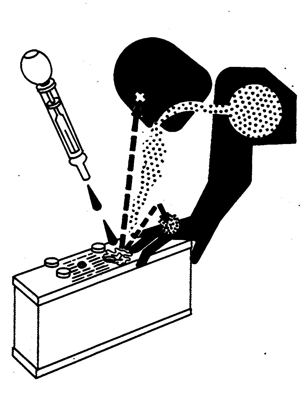
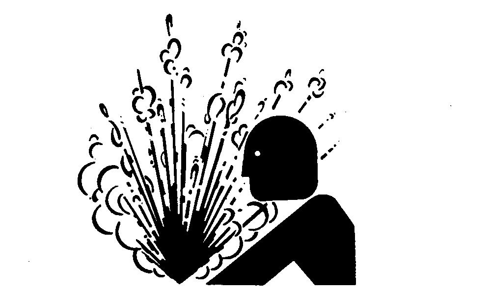
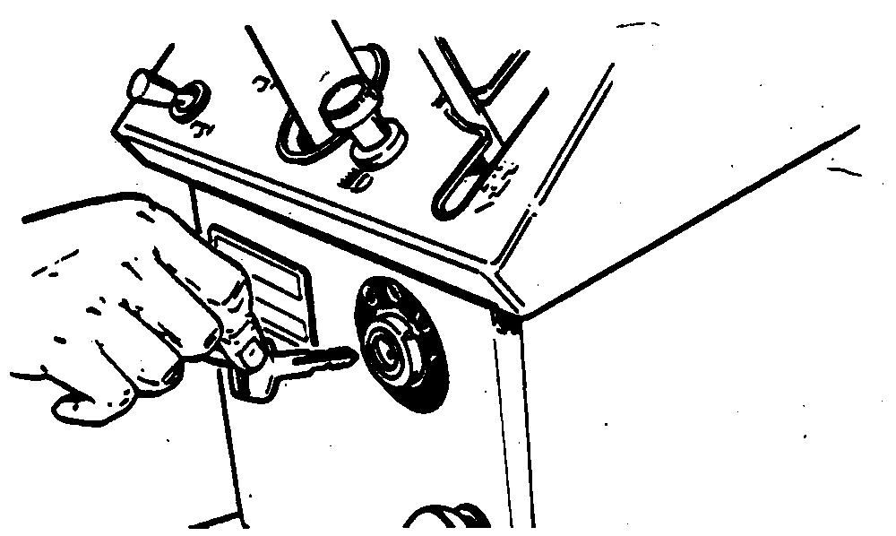
PREVENT BATTERY EXPLOSIONS
Keep sparks, lighted matches, and open flame away from the top of battery. Battery gas can explode.
Never check battery charge by placing a metal object across the posts. Use a volt-meter or hydrometer.
Do not charge a frozen battery; it may explode. Warm battery to 16˚C (60˚F).
PREPARE FOR EMERGENCIES
Be prepared if a fire starts.
Keep a first aid kit and fire extinguisher handy.
Keep emergency numbers for doctors, ambulance service, hospital, and fire department near your telephone.
PREVENT ACID BURNS
Sulfuric acid in battery electrolyte is poisonous. It is strong enough to burn skin, eat holes in clothing, and cause blindness if splashed into eyes.
Avoid the hazard by:
1. Filling batteries in a well-ventilated area.
2. Wearing eye protection and rubber gloves.
3. Avoiding breathing fumes when electrolyte is added.
4. Avoiding spilling or dripping electrolyte.
5. Use proper jump start procedure.
If you spill acid on yourself:
1. Flush your skin with water.
2. Apply baking soda or lime to help neutralize the acid.
3. Flush your eyes with water for 15—30 minutes. Get medical attention immediately.
If acid is swallowed:
1. Do not induce vomiting.
2. Drink large amounts of water or milk, but do not exceed 2 L (2 quarts).
3. Get medical attention immediately.
SERVICE COOLING SYSTEM SAFELY
Explosive release of fluids from pressurized cooling system can cause serious burns.
Shut off engine. Only remove filler cap when cool enough to touch with bare hands. Slowly loosen cap to first stop to relieve pressure before removing completely.
HANDLE CHEMICAL PRODUCTS SAFELY
Direct exposure to hazardous chemicals can cause serious injury. Potentially hazardous chemicals used with John Deere equipment include such items as lubricants, coolants, paints, and adhesives.
A Material Safety Data Sheet (MSDS) provides specific details on chemical products: physical and health hazards, safety procedures, and emergency response techniques.
Check the MSDS before you start any job using a hazardous chemical. That way you will know exactly what the risks are and how to do the job safely. Then follow procedures and recommended equipment.
(See your John Deere dealer for MSDS’s on chemical products used with John Deere equipment.)
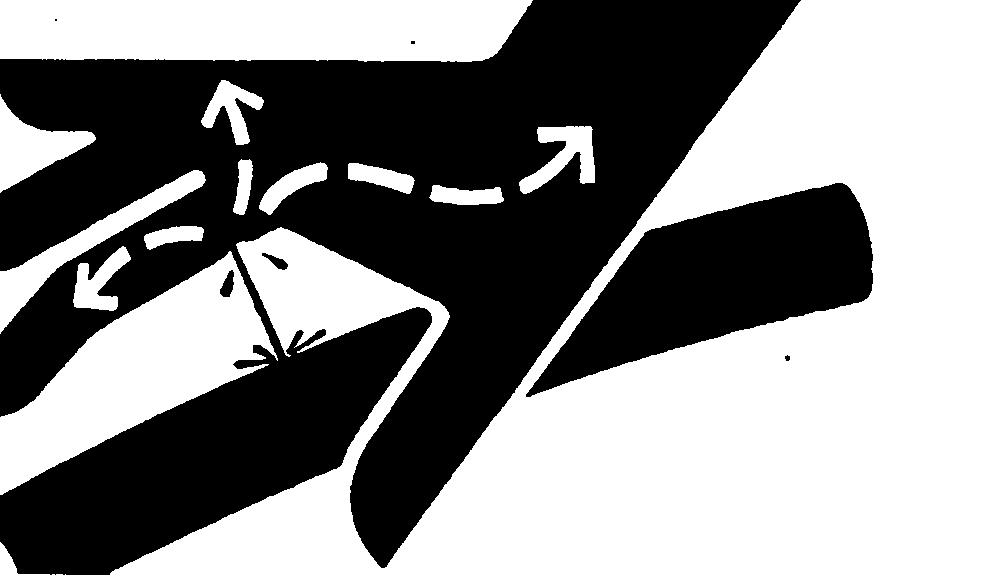
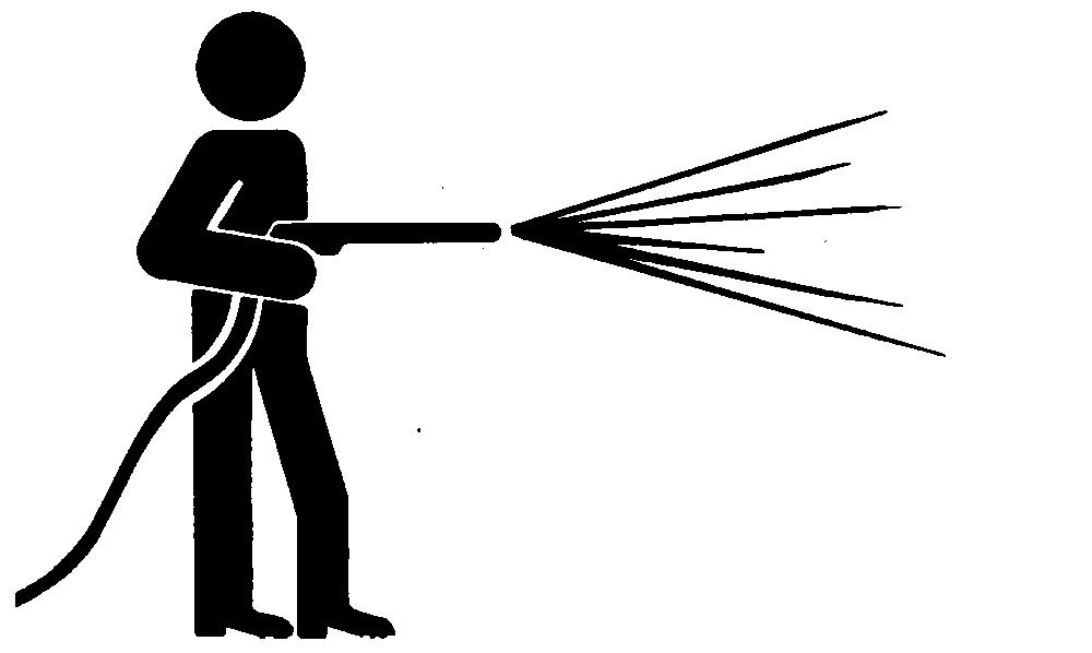
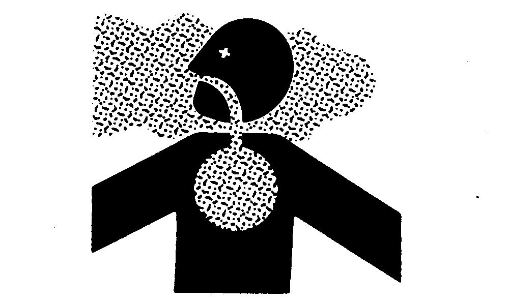
AVOID HIGH-PRESSURE FLUIDS
Escaping fluid under pressure can penetrate the skin causing serious injury.
Avoid the hazard by relieving pressure before disconnecting hydraulic or other lines. Tighten all connections before applying pressure.
Search for leaks with a piece of cardboard. Protect hands and body from high pressure fluids.
If an accident occurs, see a doctor immediately. Any fluid injected into the skin must be surgically removed within a few hours or gangrene may result. Doctors unfamiliar with this type of injury should reference a knowledgeable medical source. Such information is available from Deere & Company Medical Department in Moline, Illinois, U.S.A.
PREPARE MACHINE FOR REPAIR
1. Move hydrostatic control lever to STOP position.
2. Disengage PTO’s
3. Lower all equipment to the ground.
4. Engage park brake.
5. Stop the engine and remove the key.
6. Operate all hydraulic control levers to release hydraulic pressure in the system.
Before you leave the operator’s seat, wait for engine and attachment parts to stop moving.
SUPPORT MACHINE PROPERLY
Always lower the attachment or implement to the ground before you work on the machine. If you must work on a lifted machine or attachment, securely support the machine or attachment.
Do not support the machine on cinder blocks, hollow tiles, or props that may crumble under continuous load. Do not work under a machine that is supported solely by a jack. Follow recommended procedures in this manual.
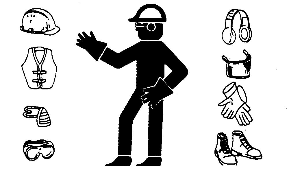
WEAR PROTECTIVE CLOTHING
Wear close fitting clothing and safety equipment appropriate to the job.
Prolonged exposure to loud noise can cause impairment or loss of hearing.
Wear a suitable hearing protective device such as earmuffs or earplugs to protect against objectionable or uncomfortable loud noises.
Operating equipment safely requires the full attention of the operator. Do not wear radio or music headphones while operating machine.
WORK IN CLEAN AREA
Before starting a job:
• Clean work area and machine.
• Make sure you have all necessary tools to do your job.
• Have the right parts on hand.
• Read all instructions thoroughly; do not attempt shortcuts.
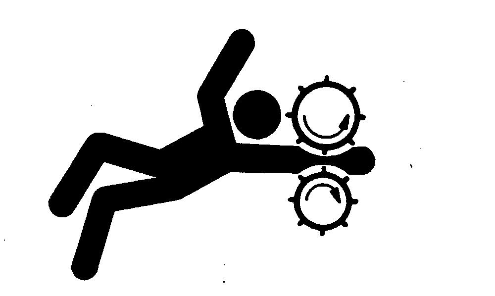
SERVICE MACHINES SAFELY
Tie long hair behind your head. Do not wear a necktie, scarf, loose clothing, or necklace when you work near machine tools or moving parts. If these items were to get caught, severe injury could result.
Remove rings and other jewelry to prevent electrical shorts and entanglement in moving parts.
WORK IN VENTILATED AREA
Engine exhaust fumes can cause sickness or death. If it is necessary to run an engine in an enclosed area, remove the exhaust fumes from the area with an exhaust pipe extension.
If you do not have an exhaust pipe extension, open the doors and get outside air into the area.
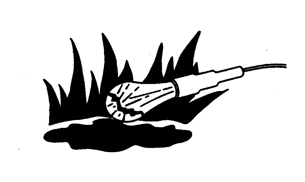
ILLUMINATE WORK AREA SAFELY
Illuminate your work area adequately but safely. Use a portable safety light for working inside or under the machine. Make sure the bulb is enclosed by a wire cage. The hot filament of an accidentally broken bulb can ignite spilled fuel or oil.
REPLACE SAFETY SIGNS
Replace missing or damaged safety signs. See the machine operator’s manual for correct safety sign placement.
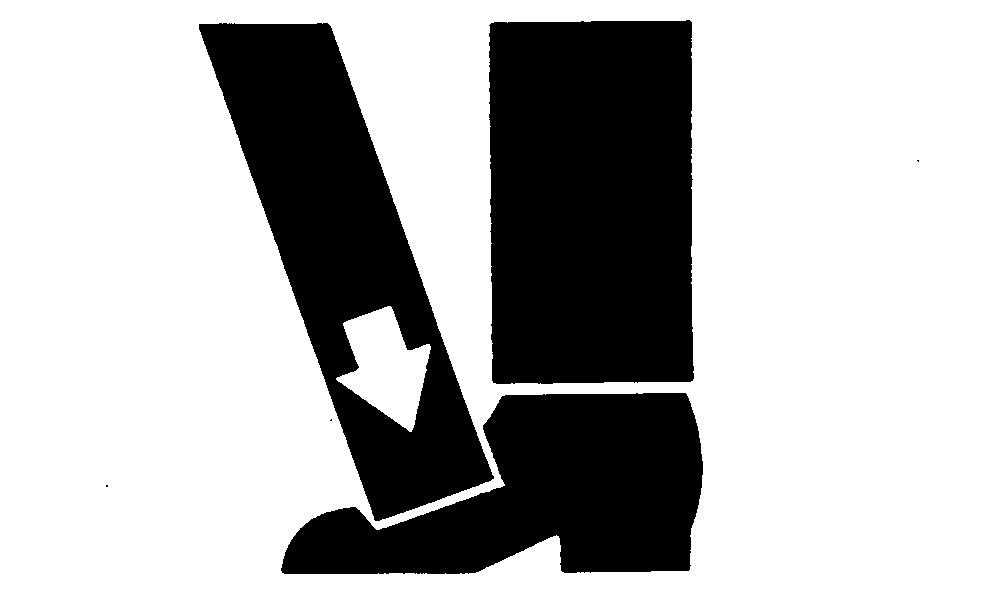
USE PROPER LIFTING EQUIPMENT
Lifting heavy components incorrectly can cause severe injury or machine damage.
Follow recommended procedure for removal and installation of components in the manual.
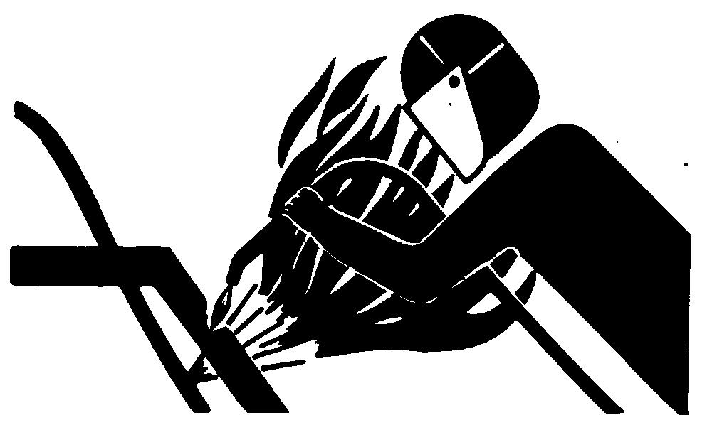
REMOVE PAINT BEFORE WELDING OR HEATING
Avoid potentially toxic fumes and dust.
Hazardous fumes can be generated when paint is heated by welding, soldering, or using a torch.
Do all work outside or in a well ventilated area. Dispose of paint and solvent properly.
Remove paint before welding or heating:
• If you sand or grind paint, avoid breathing the dust. Wear an approved respirator.
• If you use solvent or paint stripper, remove stripper with soap and water before welding. Remove solvent or paint stripper containers and other flammable material from area. Allow fumes to disperse at least 15 minutes before welding or heating.
AVOID HEATING NEAR PRESSURIZED FLUID LINES
Flammable spray can be generated by heating near pressurized fluid lines, resulting in severe burns to yourself and bystanders. Do not heat by welding, soldering, or using a torch near pressurized fluid lines or other flammable materials. Pressurized lines can be accidentally cut when heat goes beyond the immediate flame area.
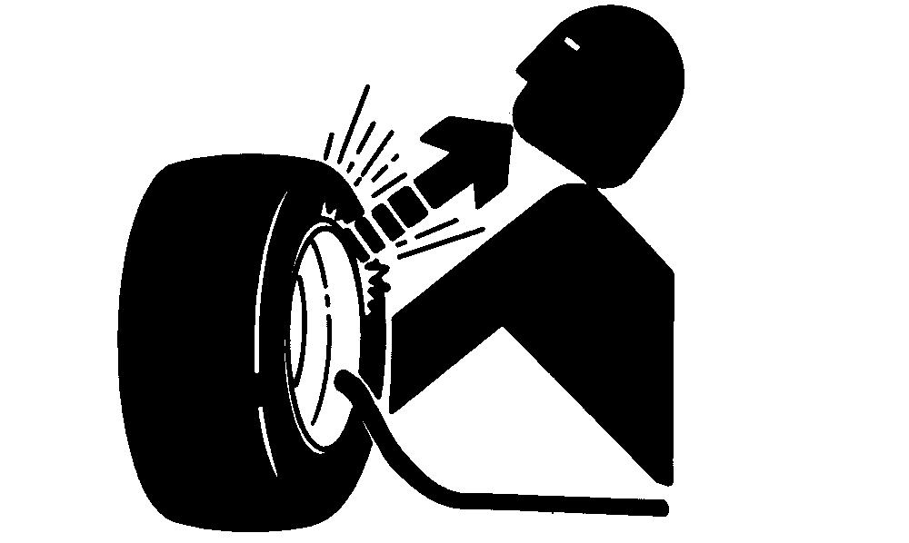
SERVICE TIRES SAFELY
Explosive separation of a tire and rim parts can cause serious injury or death.
Do not attempt to mount a tire unless you have the proper equipment and experience to perform the job.
Always maintain the correct tire pressure. Do not inflate the tires above the recommended pressure. Never weld or heat a wheel and tire assembly. The heat can cause an increase in air pressure resulting in a tire explosion. Welding can structurally weaken or deform the wheel.
When inflating tires, use a clip-on chuck and extension hose long enough to allow you to stand to one side and NOT in front of or over the tire assembly. Use a safety cage if available.
Check wheels for low pressure, cuts, bubbles, damaged rims or missing lug bolts and nuts.
AVOID HARMFUL ASBESTOS DUST
Avoid breathing dust that may be generated when handling components containing asbestos fibers. Inhaled asbestos fibers may cause lung cancer.
Components in products that may contain asbestos fibers are brake pads, brake band and lining assemblies, clutch plates, and some gaskets. The asbestos used in these components is usually found in a resin or sealed in some way. Normal handling is not hazardous as long as airborne dust containing asbestos is not generated.
Avoid creating dust. Never use compressed air for cleaning. Avoid brushing or grinding material containing asbestos. When servicing, wear an approved respirator. A special vacuum cleaner is recommended to clean asbestos. If not available, apply a mist of oil or water on the material containing asbestos.
Keep bystanders away from the area.
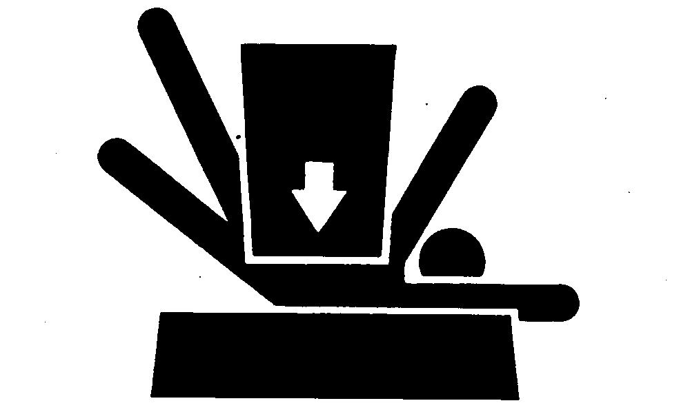
PRACTICE SAFE MAINTENANCE
Understand service procedure before doing work. Keep area clean and dry.
Never lubricate, service, or adjust machine while it is moving. Keep hands, feet , and clothing from power-driven parts. Disengage all power and operate controls to relieve pressure. Lower equipment to the ground. Stop the engine. Remove the key. Allow machine to cool.
Securely support any machine elements that must be raised for service work.
Keep all parts in good condition and properly installed. Fix damage immediately. Replace worn or broken parts. Remove any buildup of grease, oil, or debris.
Disconnect battery ground cable (-) before making adjustments on electrical systems or welding on machine.
USE PROPER TOOLS
Use tools appropriate to the work. Makeshift tools and procedures can create safety hazards.
Use power tools only to loosen threaded parts and fasteners.
For loosening and tightening hardware, use the correct size tools. DO NOT use U.S. measurement tools on metric fasteners. Avoid bodily injury caused by slipping wrenches.
Use only service parts meeting John Deere specifications.
DISPOSE OF WASTE PROPERLY
Improperly disposing of waste can threaten the environment and ecology. Potentially harmful waste used with John Deere equipment include such items as oil, fuel, coolant, brake fluid, filters, and batteries.
Use leakproof containers when draining fluids. Do not use food or beverage containers that may mislead someone into drinking from them.
Do not pour waste onto the ground, down a drain, or into any water source.
Air conditioning refrigerants escaping into the air can damage the Earth’s atmosphere. Government regulations may require a certified air conditioning service center to recover and recycle used air conditioning refrigerants.
Inquire on the proper way to recycle or dispose of waste from your local environmental or recycling center, or from your John Deere dealer.
LIVE WITH SAFETY
Before returning machine to customer, make sure machine is functioning properly, especially the safety systems. Install all guards and shields.
Group 10
MACHINE SPECIFICATIONS—322 AND 330
ENGINE
Manufacturer
Engine Rated Speeds
Fast Idle (No Load)
Air Filter Type Dry with Primary and Dry with Primary and Secondary Elements
Lubrication System
Pressure w/Filter
Secondary Elements
Pressure w/Filter
Crankcase Capacity (w/o Filter) 2.5 L (2.6 U.S. qt) 2.5 L (2.6 U.S. qt)
Oil Filter Replaceable Replaceable
Spark Plugs NGK BPR4BS N/A Champion RN11YC
FUEL SYSTEM
Fuel Tank Location Rear Rear
Fuel Gauge Standard Standard
Fuel Tank Capacity 17 L (4.5 U.S. gal) 17 L (4.5 U.S. gal)
Fuel 85 Octane Unleaded No.1 or No.2 Diesel
Fuel Pump Location Frame Frame
Fuel Pump Type
Fuel Delivery
Electric
. Fixed Jet Carburetor .
Electric
. . Indirect Injection
Injection Pump Type N/A In-Line Multi-Plunger
Fuel Shutoff Electric Solenoid Manual
ELECTRICAL SYSTEM
Ignition Electronic N/A
Type of Starter
12 Volts, Solenoid
12 Volts, Solenoid
Charging System Remote Alt. 20 amp Remote Alt. 20 amp
Steering Shaft Universal Joint-to-Worm Shaft Cap Screw Torque
Steering—322, 332 and 430
Steering Wheel-to-Shaft Nut Torque
Rotor-to-Stator Maximum Allowable Clearance
Steering Tube Bushing Depth
Commutator Cover-to-Commutator Screw Torque
Ball Plug Torque (Early Version)
Cylinder Mounting Nut Torque
Brakes
Brake Plate-to-Axle Housing Cap Screw Torque
Axle Housing-to-Frame Cap Screw Torque
Brake Rod Spring Length
Brake Drum-to-Axle Nut Torque
HYDRAULICS Single-Spool
Check Valve Plug Torque
Two-Spool Valve
Versions One and Two
Spool Cap-to-Body Screw Torque
Versions Three and Four
Spool Screw and Detent Torque
Spool Cap-to-Body Screw Torque
Check Valve Plug Torque
Three-Spool Valve
Spool Screws and Detent Torque
Spool Cap-to-Body Screw Torque
Check Valve Plug Torque
(44
(65
N·m (23 lb-ft)
(35 lb-in.)
N·m (23 lb-ft)
MISCELLANEOUS
Front Axle
PTO Belt Tension Spring Length (430)
Toe-In
Mower Blade Spindles
Driven Sheave-to-Spindle Lock Nut Torque
Blade-to-Spindle Cap Screw Torque
Mower Blade Jack Sheave
Jack Sheave-to-Spindle Lock Nut Torque
Cap Screw Torque
50-Inch Mower Gear Case
Plug Installation Depth
Retainer Seal Installation Depth
Retainer-to-Gear Case Cap Screw Torque
Pillow Block Seal Installation Depth
Pillow Block-to-Gear Case Cap Screw Torque
Early 60-Inch Mower Gear Case
Cap-to-Gear Case Cap Screw Torque
Output Shaft Endplay
Input Shaft Backlash
Later 60-Inch Mower Gear Case
mm (1.380 in.)
mm (3/16 in.)
N·m (103
N·m (54
N·m (22 lb-ft)
N·m (22 lb-ft)
mm (0.001—0.003 in.)
. 0.076—0.130 mm (0.003—0.005 in.)
Gear Case Seal Installation Depth 2.54 mm (0.100 in.) below gear case surface
Retainer-to-Gear Case Cap Screw Torque
N·m (22 lb-ft) Pillow Block Seal Installation Depth
Pillow Block-to-Gear Case Cap Screw Torque
260 Rotary Mower Gear Case
End Cap-to-Gear Case Cap Screw Torque
N·m (22 lb-ft)
N·m (22 lb-ft)
Input Shaft Endplay 0.025—0.076 mm (0.001—0.003 in.)
Output Shaft Backlash 0.076—0.130 mm (0.003—0.005 in.)
Housing-to-Gear Case Cap Screw Torque 30 N·m (22 lb-ft)
MX,15911015,3 -19-13JUL95
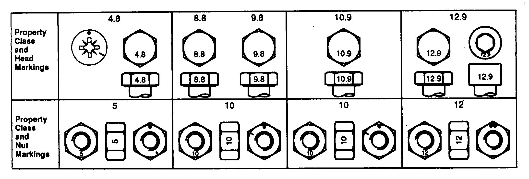
METRIC BOLT AND CAP SCREW TORQUE VALUES
DO NOT use these values if a different torque value or tightening procedure is given for a specific application. Torque values listed are for general use only. Check tightness of fasteners periodically.
Shear bolts are designed to fail under predetermined loads. Always replace shear bolts with identical property class.
Fasteners should be replaced with the same or higher property class. If higher property class fasteners are used, these should only be tightened to the strength of the original.
a “Lubricated” means coated with a lubricant such as engine oil, or fasteners with phosphate and oil coatings. “Dry” means plain or zinc plated without any lubrication.
Make sure fasteners threads are clean and that you properly start thread engagement. This will prevent them from failing when tightening.
Tighten plastic insert or crimped steel-type lock nuts to approximately 50 percent of the dry torque shown in the chart, applied to the nut, not to the bolt head. Tighten toothed or serrated-type lock nuts to the full torque value.
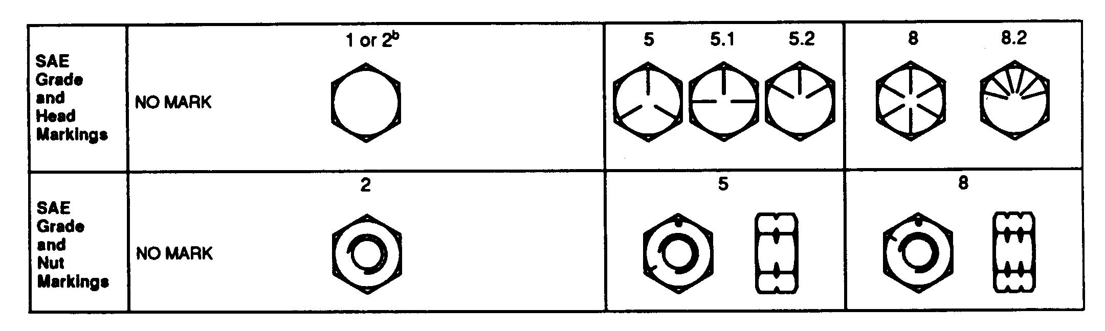
UNIFIED INCH BOLT AND CAP SCREW TORQUE VALUES
DO NOT use these values if a different torque value or tightening procedure is given for a specific application. Torque values listed are for general use only. Check tightness of fasteners periodically.
Shear bolts are designed to fail under predetermined loads. Always replace shear bolts with identical grade.
Fasteners should be replaced with the same or higher grade. If higher grade fasteners are used, these should only be tightened to the strength of the original.
Make sure fasteners threads are clean and that you properly start thread engagement. This will prevent them from failing when tightening.
a “Lubricated” means coated with a lubricant such as engine oil, or fasteners with phosphate and oil coatings. “Dry” means plain or zinc plated without any lubrication.
b Grade 2 applies for hex cap screws (not hex bolts) up to 152 mm (6-in.) long. Grade 1 applies for hex cap screws over 152 mm (6-in.) long, and for all other types of bolts and screws of any length.
Tighten plastic insert or crimped steel-type lock nuts to approximately 50 percent of the dry torque shown in the chart, applied to the nut, not to the bolt head. Tighten toothed or serrated-type lock nuts to the full torque value.
METRIC CAP SCREW TORQUE VALUES—GRADE 7
NOTE: When bolting aluminum parts, tighten to 80% of torque specified in table.
Size N·m (lb-ft)
M6 9.5 - 12.2 (7-9)
M8 20.3 - 27.1 (15-20)
M10 47.5 - 54.2 (35-40)
M12 81.4 - 94.9 (60-70)
M14
- 146.4 (95-108)
M16 210.2 - 240 (155-177)
NOTE: Allow a tolerance of plus or minus 10 per cent on all torques given in this chart.
Divide readings by 12 for foot-pound values.
MX,15901015,3 -19-01MAR95 MX,TORQ,SET -19-09DEC94
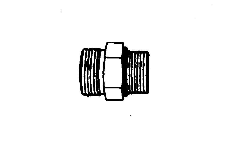
SERVICE RECOMMENDATIONS FOR O-RING BOSS FITTINGS
STRAIGHT FITTING
1. Inspect O-ring boss seat for dirt or defects.
2. Lubricate O-ring with petroleum jelly. Place electrical tape over threads to protect O-ring. Slide O-ring over tape and into O-ring groove of fitting. Remove tape.
3. Tighten fitting to torque value shown on chart.
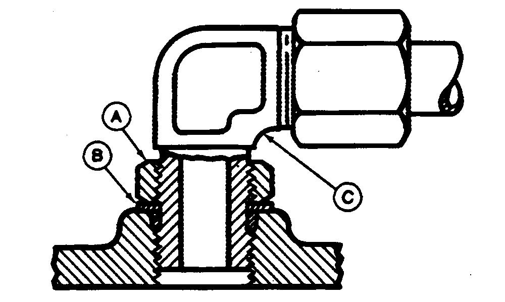
ANGLE FITTING
1. Back-off lock nut (A) and back-up washer (B) completely to head-end (C) of fitting.
2. Turn fitting into threaded boss until back-up washer contacts face of boss.
3. Turn fitting head-end counterclockwise to proper index (maximum of one turn).
4. Hold fitting head-end with a wrench and tighten locknut and back-up washer to proper torque value.
NOTE: Do not allow hoses to twist when tightening fittings. TORQUE
NOTE: Torque tolerance is ± 10%.
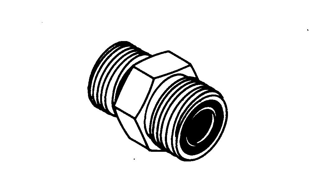
SERVICE RECOMMENDATIONS FOR FLAT FACE O-RING SEAL FITTINGS
1. Inspect the fitting sealing surfaces. They must be free of dirt or defects.
2. Inspect the O-ring. It must be free of damage or defects.
3. Lubricate O-rings and install into groove using petroleum jelly to hold in place.
4. Push O-ring into the groove with plenty of petroleum jelly so O-ring is not displaced during assembly.
5. Index angle fittings and tighten by hand pressing joint together to insure O-ring remains in place.
6. Tighten fitting or nut to torque valve shown on the chart per dash size stamped on the fitting. Do not allow hoses to twist when tightening fittings.
NOTE: Torque tolerance is +15 -20%.
TUBE AND HOSE FITTING, 37˚ FLARE AND 30˚ CONE SEAT CONNECTOR SERVICE RECOMMENDATIONS
1. Inspect the flare and the flare seat. They must be free of dirt and defects. If repeated leaks occur, inspect for defects with a magnifying glass. If burrs and raised nicks on the connector body cannot be removed with a slip stone, replace the connector.
2. Defects in the tube flare cannot be repaired. Replace the tube. Overtightening a defective flared fitting will not stop leaks.
3. As a field repair, a ductile truncated cone shaped washer can be used between the tube flare and connector body. These washers are soft enough to fill defects in the seat and flare. They will also seal the connection. Ductile washers are available from industrial supply houses.
4. Align the tube with the fitting before attempting to start the nut. Failure to do so can cause a deformed flare and subsequent leaks. Install hoses without twists. A twisted hose attempts to straigten out when pressure is applied. This exerts a torque on the connection, eventually causing failure.
5. Lubricate the connection with hydraulic fluid, petroleum jelly or soap. Tighten the swivel nut by hand until it is snug.
6. Mark a line across the nut and connector body. This line will serve as a visual indicator as to whether the nut has been tightened and by how much.
7. Using two wrenches, one on the connector body and a torque wrench on the nut, tighten the nut to the torque value as shown in the chart. In the case of a hose, it may be necessary to use three wrenches to prevent twisting.
AND HOSE FITTING,
FLARE AND
CONE SEAT CONNECTOR TORQUE
1. Tolerance of ± 10 percent.
2. To be used if a torque wrench cannot be used. After tightening fitting by hand, put a mark across the fittings, then tighten fitting the number of flats shown.
3. Flare connection seal by deforming or squeezing the tube between the nut and the connector. More deformation is possible with new parts than with old. Therefore, if a torque rench is not used for re-assembly, the values in this column must be used to revent damage.
Group
TEST AND ADJUSTMENT SPECIFICATIONS
Item
ENGINE—322
Slow Idle Speed 3TG66UJ
Fast Idle Speed
3TG66UJ
Fuel Pump
Minimum Fuel Flow
3TG66UJ
Minimum Fuel Pressure
Choke Plate Clearance (Later models)
Oil Pressure 3TG66UJ
Spark Plug Gap
3TG66UJ
Cooling System Pressure Test 3TG66UJ
Minimum Pressure After After 15 Seconds
Radiator Cap Opening Pressure 3TG66UJ
Compression Minimum
3TG66UJ
Maximum Difference Between Cylinders
Engine Cranking Speed 3TG66UJ
Test and Adjustment Specifications
Item
ENGINE—330, 332, and 430
Fuel Pump
Minimum Fuel Flow 3TN66UJ
seconds 3TNA72UJ
Minimum Fuel Pressure
3TN66UJ
Compression
Maximum Difference Between Cylinders
3TN66UJ
Oil
Slow Idle Speed
3TN66UJ and Later 3TNA72UJ
Early 3TNA72UJ
Fast Idle Speed 3TN66UJ and Later 3TNA72UJ
3TNA72UJ
Cooling System Pressure Test
3TN66UJ
Radiator Cap
Opening Pressure
After After 15 Seconds
Fuel Injection Pump Cover Nut Torque
3TN66UJ and Later 3TNA72UJ
Fuel Injection Pump Cover Cap Screw Torque Early 3TNA72UJ
(20 oz.)/30 seconds
-19-13JUL95
ELECTRICAL SYSTEM
Pulser Coils—322
Ignition Coils—322
Coil Resistance
Secondary Coil Resistance
Glow Plugs—330, 332 and 430
Resistance
PTO Clutch Armature-to-Rotor Clearance
Starter—322, 330 and 332
Draw (Maximum)
rpm (Minimum)
No-Load Amp Draw (Maximum)
Starter—430
Draw (Maximum)
(Minimum)
Amp Draw (Maximum)
Fuel Shutoff Solenoid (430 S.N. —420468)
Lever-to-Stop Clearance
Alternator—322, 330 and 332
Alternator—430
Regulated Voltage Output
—420468)
420469— )
POWER TRAIN
(Minimum)
Oil Temperature for Hydraulic Tests
(110˚F) Charge Pump Pressure
Implement Relief Valve Pressure
kPa (850—975 psi)
Minimum Charge Pump Flow at 3450 kPa (500 psi) 11 L/min (3 gpm) 322, 332 and 430; Steering Valve Pressure in Neutral Position 620—1240 kPa (90—180 psi)
Hydrostatic Lever Tension 31—44.5 N (7—10 lb force)
Turnbuckle Lock Nut Torque
(Transmission Control Lever Linkage, 330 and Version One—322, 332 and 430)
Detent Spring Length (Transmission Control Lever Linkage, Later Versions—322, 332 and 430)
-19-13JUL95
A
Air Cleaner and Radiator Screen Check . . 220-05-2
Alternator Tests—322, 330 and 332
Regulated Current Output
Regulated Voltage Output
Unregulated Voltage Output
Alternator Tests—430
Regulated Volt/Amp Output
240-25-12
240-25-11
240-25-11
240-25-13
Unreg. Current Output (SN —420468) 240-25-14
Unreg. Current Output (SN 420469— ) 240-25-15
B
Battery, Charge and Test
Bleed Fuel Injection System
330 and 332
240-20-4
430 220-11-8
Bleed Hydraulic System 270-20-8
Brake Pedal Linkage
322 and 332
330 60-10-8
430 60-10-14
Brake Switch
Neutral Start, Check
Brakes Adjust
240-05-3
60-10-7
C
Carburetor Idle Mixture Screw (322) Adjustment
Charge Pump
Assemble
Disassemble and Inspect
50-05-4
Flow Test 250-15-8
Pressure Test
Remove and Install
Suction Line Check 250-15-6
Charge Relief Valve
Charging System Tests—322, 330 and 332 Regulated Current Output