6010, 6110, 6210, 6310, 6410, 6510, 6610, 6810, 6910, 6910S and SE Tractors
DIAGNOSIS AND TESTS SERVICE MANUAL
6210, 6410, 6510, 6610, 6810, 6910, 6010, 6110, 6310, SE6510, SE6610, SE6010, SE6110, SE6310, SE6410, 6910S

John Deere Agriculture
tm4552, March 2003
Table of contents
FOREWORD
Section 210 - SAFETY
Group 05 - Safety
Section 211 - SERVICE CODE DIAGNOSTICS
Group BCU - BCU Service Code Diagnostics
Group BIF - BIF Service Code Diagnostics
Group ECU (Level - ECU (Level 1 with LUCAS injection pump) Service Code Diagnostics
Group ECU (Level - ECU (Level 4 with BOSCH VP44 injection pump) Service Code Diagnostics
Group HCU - HCU Service Code Diagnostics
Group PCU - PCU Service Code Diagnostics
Group PEC - PEC Service Code Diagnostics
Group PLC - PLC Service Code Diagnostics
Group RCU - RCU Service Code Diagnostics
Group SFA - SFA Service Code Diagnostics
Group TCU - TCU Service Code Diagnostics
Group UIC - UIC Service Code Diagnostics
Section 212 - OBSERVABLE SYMPTOMS
Group 40 - Electrical System
Group 55 - PowrQuad, PowrQuad Plus and AutoQuad Transmissions
Group 56 - Drive System (except transmission)
Group 60 - Steering and Brakes
Group 70 - Hydraulic System
Section 220 - ENGINE
Group 10 - Tests
Section 230 - FUEL, AIR INTAKE AND COOLING SYSTEMS
Group 10 - System Diagnosis
Group 15 - Tests and Adjustments
Group 20A - Fuel System
Group 20B - Air Intake System
Group 20C - Cooling System
Group 20D - Cold-Weather Starting Aids
Section 240 - ELECTRICAL SYSTEM
Group 05 - General
Group 10 - Functional Schematics and Wiring Diagrams (6010-6910S)
Group 10A - Functional Schematics and Wiring Diagrams (SE Tractors)
Group 10B - Functional Schematics and Wiring Diagrams (2-Post ROPS)
Group 10C - Functional Schematics and Wiring Diagrams (AutoPowr)
Group 15 - Circuit Testing (6010-6910S with Cab)
Group 15A - Sub-System Diagnostics (SE Tractors)
Group 15B - Sub-System Diagnostics (2-Post ROPS)
Group 15C - Circuit Testing (AutoPowr Transmission)
Group 16A - Data BUS Systems
Group 16B - Data BUS Systems -- Diagnosis
Group 20 - Adjustments
Group 25 - Component Testing
Section 245 - ELECTRONIC CONTROL UNITS
Group 05 - Operation and General Information on Diagnostics
Group BCU - BCU References
tm4552-DIAGNOSIS AND TESTS SERVICE MANUAL (g) by Belgreen <- Go to Global Table of contents tm4552-DIAGNOSIS AND TESTS SERVICE MANUAL
Group BIF - BIF References
Group ECU - ECU (Level 1) References
Group HCU - HCU References
Group PCU - PCU References
Group PEC - PEC References
Group PLC - PLC References
Group RCU - RCU References
Group SFA - SFA References
Group TCU - TCU References
Group UIC - UIC References
Section 250 - SYNCROPLUS TRANSMISSION
Group 05 - Operational Checkout
Group 10 - Troubleshooting
Group 15 - Tests and Adjustments
Group 20 - SyncroPlus Transmission Operation
Group 20A - Perma Clutch II
Group 20B - Gear Transmission
Group 20C - Creeper Transmission
Group 20D - Range Transmission
Section 251 - POWER REVERSER TRANSMISSION
Group 05 - Operational Checkout
Group 10 - Troubleshooting
Group 15 - Test and Adjustments
Group 20 - Power Reverser Operation
Group 20A - Power Reverser Module
Group 20B - Gear Transmission
Section 252 - POWER SHIFT TRANSMISSION
Group 05 - Operational Checkout
Group 10 - Troubleshooting
Group 15 - Adjustments
Group 20 - Theory of Operation
Section 253 - AUTOPOWR TRANSMISSION
Group 10A - Diagnosis - UIC
Group 10B - Diagnosis - TCU
Group 10C - Diagnosis - PLC
Group 15 - Tests and Adjustments
Group 20 - Operation
Section 255 - POWRQUAD, POWRQUAD PLUS AND AUTOQUAD II TRANSMISSIONS
Group 05 - Operational Checkout
Group 10A - POWRQUADPOWRQUAD is a trademark of Deere & Company.Transmission Check
Group 10B - Troubleshooting on PowrQuad Plus and AutoQuad II
Group 15 - Tests and Adjustments
Group 20A - PowrQuad Transmission Operation
Group 20B - PowrQuad Plus and AutoQuad II Transmission Operation
Group 20C - Creeper Transmission
Group 20D - Range Transmission
Section 256 - DRIVE SYSTEMS
Group 05 - Operational Checkout
Group 10 - Troubleshooting
tm4552-DIAGNOSIS AND TESTS SERVICE MANUAL (g) by Belgreen <- Go to Global Table of contents tm4552-DIAGNOSIS AND TESTS SERVICE MANUAL
Group 15 - Tests
Group 20A - Front-Wheel Drive Clutch
Group 20B - Differential
Group 20C - Final Drives
Group 20D - Rear PTO Options
Group 20E - Front PTO
Section 260 - STEERING AND BRAKES
Group 05 - Operational Checkout
Group 10 - Troubleshooting
Group 15 - Tests and Adjustments
Group 20A - Hydrostatic Steering
Group 20B - Hydraulic Brakes
Group 20C - Handbrake
Group 20D - Hydraulic Trailer Brake
Group 20E - Air Brake System
Section 270 - HYDRAULIC SYSTEM
Group 05 - Operational Checkout
Group 10 - PFC Hydraulic System Troubleshooting
Group 11 - PC Hydraulic System Troubleshooting
Group 15 - Tests and Adjustments
Group 20 - PFC Hydraulic System
Group 20A - Charge Oil Pump
Group 20B - Hydraulic Pumps
Group 20C - Valves, Oil Cooler and Filter
Group 20D - Rockshaft
Group 20E - Selective Control Valves and Couplers
Group 20F - Independent Control Valve (ICV)
Group 21 - PC Hydraulic System and Components
Section 280 - MISCELLANEOUS
Group 05 - TLS Front Axle Operational Checkout
Group 10 - TLS Front Axle Troubleshooting
Group 15 - TLS Front Axle Tests and Adjustments
Group 20 - TLS Front Axle Operation
Section 290 - OPERATORS CAB
Group 05 - Operational Checkout
Group 10A - Air Conditioner Troubleshooting
Group 10B - Ventilation and Heater Troubleshooting
Group 10C - Operator´s Seat Troubleshooting
Group 20A - Air Conditioner Operation
Group 20B - Ventilation and Heating Operation
Section 299 - SPECIAL TOOLS (DEALER-FABRICATED)
Group 05 - Special Tools (Dealer-Fabricated)
tm4552-DIAGNOSIS AND TESTS SERVICE MANUAL (g) by Belgreen <- Go to Global Table of contents tm4552-DIAGNOSIS AND TESTS SERVICE MANUAL
<- Go to Global Table of contents tm4552-DIAGNOSIS AND TESTS SERVICE MANUAL
Foreword
This "Operation and Test" manual applies to the following types of tractor:
6010, 6110, 6210, 6310, 6410, 6510, 6610, 6810, 6910 and 6910S.
SE tractors 6010, 6110, 6210, 6310, 6410, 6510 and 6610.
This manual is written for an experienced technician. Essential tools required in performing certain service work are identified in this manual and are recommended for use.
Live with safety: Read the safety messages in the introduction of this manual and the cautions presented throughout the text of the manual.
This is the safety-alert symbol. When you see this symbol on the machine or in this manual, be alert to the potential for personal injury.

Technical Manuals are concise guides for specific machines. They are on-the-job guides containing only the vital information needed for diagnosis, analysis, testing, and repair.
Fundamental service information is available from other sources covering basic theory of operation, fundamentals of troubleshooting, general maintenance, and basic type of failures and their causes.
<- Go to Global Table of contents tm4552-DIAGNOSIS AND TESTS SERVICE MANUAL SAFETY (g) by Belgreen
tm4552-DIAGNOSIS AND TESTS SERVICE MANUAL (g) by Belgreen <- Go to Global Table of contents tm4552-DIAGNOSIS AND TESTS SERVICE MANUAL Section 210 - SAFETY Table of contents Group 05 - Safety 1 Recognize Safety Information 1 'Important" - Information .........................................................................................................................1 'Note" - Information....................................................................................................................................1 Prevent Machine Runaway 1 Handle Fluids Safely-Avoid Fires .............................................................................................................2 Prevent Battery Explosions.......................................................................................................................3 Prepare for Emergencies 3 Prevent Acid Burns.....................................................................................................................................4 Avoid High-Pressure Fluids 5 Service Cooling System Safely 5 Remove Paint Before Welding or Heating..............................................................................................6 Avoid Heating Near Pressurized Fluid Lines 7 Work In Ventilated Area Wear Protective Clothing 7 .......................................................................................................................8 Practice Safe Maintenance 9 Park Machine Safely 10 Use Proper Lifting Equipment.................................................................................................................10 Construct Dealer-Made Tools Safely ......................................................................................................11 Support Machine Properly 11 Work in Clean Area ..................................................................................................................................12 Illuminate Work Area Safely ....................................................................................................................13 Service Machines Safely 13 Use Proper Tools ......................................................................................................................................14 Service Tires Safely ................................................................................................................................. 14 Service Front-Wheel Drive Tractor Safely 16 Safety Information - Air Brake System ..................................................................................................16 Avoid Eye Contact with Radar Keep ROPS Installed Properly . 17 18 Replace Safety Signs .............................................................................................................................. 18 Dispose of Waste Properly 19 Live With Safety 20
Group 05 - Safety
Recognize Safety Information
This is a safety-alert symbol. When you see this symbol on your machine or in this manual, be alert to the potential for personal injury.

Follow recommended precautions and safe operating practices.
”Important” - Information
Information marked as IMPORTANT points out problems that may lead to machine damage. By following the directions given, these problems can be avoided.
”Note” - Information
When marked with NOTE the information given is more detailed or contains restrictions to directions given previously. On the other hand useful information may be given belonging to certain instructions without being directly connected to them.
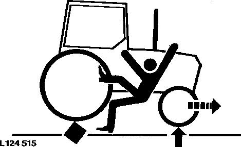
Prevent Machine Runaway
Section 210 - SAFETY Group 05: Safety tm4552-DIAGNOSIS AND TESTS SERVICE MANUAL Section 210 page 1 <- Go to Section TOC
Avoid possible injury or death from machinery runaway.

Do not start engine by shorting across starter terminals. Machine will start in gear if normal circuitry is bypassed.
NEVER start engine while standing on ground. Start engine only from operator´s seat, with transmission in neutral or park.
Handle Fluids Safely-Avoid Fires
When you work around fuel, do not smoke or work near heaters or other fire hazards.
Store flammable fluids away from fire hazards. Do not incinerate or puncture pressurized containers.
Make sure machine is clean of trash, grease, and debris.

Section 210 - SAFETY Group 05: Safety tm4552-DIAGNOSIS AND TESTS SERVICE MANUAL Section 210 page 2 <- Go to Section TOC
Do not store oily rags; they can ignite and burn spontaneously.
Prevent Battery Explosions
Keep sparks, lighted matches, and open flame away from the top of battery. Battery gas can explode.


Never check battery charge by placing a metal object across the posts. Use a volt-meter or hydrometer.
Do not charge a frozen battery; it may explode. Warm battery to 16°C (60°F).
Prepare for Emergencies
Be prepared if a fire starts.
Section 210 - SAFETY Group 05: Safety tm4552-DIAGNOSIS AND TESTS SERVICE MANUAL Section 210 page 3 <- Go to Section TOC
Keep a first aid kit and fire extinguisher handy.
Keep emergency numbers for doctors, ambulance service, hospital, and fire department near your telephone.
Prevent Acid Burns
Sulfuric acid in battery electrolyte is poisonous. It is strong enough to burn skin, eat holes in clothing, and cause blindness if splashed into eyes.
Avoid the hazard by:
1. Filling batteries in a well-ventilated area.
2. Wearing eye protection and rubber gloves.

Section 210 - SAFETY Group 05: Safety tm4552-DIAGNOSIS AND TESTS SERVICE MANUAL Section 210 page 4 <- Go to Section TOC
3. Avoiding breathing fumes when electrolyte is added.
4. Avoiding spilling or dripping electrolyte.
5. Use proper jump start procedure.

If you spill acid on yourself:
1. Flush your skin with water.
2. Apply baking soda or lime to help neutralize the acid.
3. Flush your eyes with water for 15-30 minutes. Get medical attention immediately.
If acid is swallowed:
1. Do not induce vomiting.
2. Drink large amounts of water or milk, but do not exceed 2 L (2 quarts).
3. Get medical attention immediately.
Avoid High-Pressure Fluids
Escaping fluid under pressure can penetrate the skin causing serious injury.
Avoid the hazard by relieving pressure before disconnecting hydraulic or other lines. Tighten all connections before applying pressure.
Search for leaks with a piece of cardboard. Protect hands and body from high pressure fluids.
If an accident occurs, see a doctor immediately. Any fluid injected into the skin must be surgically removed within a few hours or gangrene may result. Doctors unfamiliar with this type of injury should reference a knowledgeable medical source. Such information is available from Deere & Company Medical Department in Moline, Illinois, U.S.A.
Section 210 - SAFETY Group 05: Safety tm4552-DIAGNOSIS AND TESTS SERVICE MANUAL Section 210 page 5 <- Go to Section TOC
Service Cooling System Safely
Explosive release of fluids from pressurized cooling system can cause serious burns.
Shut off engine. Only remove filler cap when cool enough to touch with bare hands. Slowly loosen cap to first stop to relieve pressure before removing completely.
Remove Paint Before Welding or Heating
Avoid potentially toxic fumes and dust.

Hazardous fumes can be generated when paint is heated by welding, soldering, or using a torch.
Remove paint before heating:

Section 210 - SAFETY Group 05: Safety tm4552-DIAGNOSIS AND TESTS SERVICE MANUAL Section 210 page 6 <- Go to Section TOC
Remove paint a minimum of 76 mm (3 in.) from area to be affected by heating.
If you sand or grind paint, avoid breathing the dust. Wear an approved respirator.
If you use solvent or paint stripper, remove stripper with soap and water before welding. Remove solvent or paint stripper containers and other flammable material from area. Allow fumes to disperse at least 15 minutes before welding or heating.
Do all work in an area that is ventilated to carry toxic fumes and dust away.
Dispose of paint and solvent properly.
Avoid Heating Near Pressurized Fluid Lines
Flammable spray can be generated by heating near pressurized fluid lines, resulting in severe burns to yourself and bystanders. Do not heat by welding, soldering, or using a torch near pressurized fluid lines or other flammable materials. Pressurized lines can be accidentally cut when heat goes beyond the immediate flame area.
Work In Ventilated Area

Section 210 - SAFETY Group 05: Safety tm4552-DIAGNOSIS AND TESTS SERVICE MANUAL Section 210 page 7 <- Go to Section TOC
Engine exhaust fumes can cause sickness or death. If it is necessary to run an engine in an enclosed area, remove the exhaust fumes from the area with an exhaust pipe extension.
If you do not have an exhaust pipe extension, open the doors and get outside air into the area
Wear Protective Clothing

Section 210 - SAFETY Group 05: Safety tm4552-DIAGNOSIS AND TESTS SERVICE MANUAL Section 210 page 8 <- Go to Section TOC
Wear close fitting clothing and safety equipment appropriate to the job.
Prolonged exposure to loud noise can cause impairment or loss of hearing.

Wear a suitable hearing protective device such as earmuffs or earplugs to protect against objectionable or uncomfortable loud noises.
Operating equipment safely requires the full attention of the operator. Do not wear radio or music headphones while operating machine.
Practice Safe Maintenance
Understand service procedure before doing work. Keep area clean and dry.
Never lubricate, service, or adjust machine while it is moving. Keep hands, feet , and clothing from power-driven parts. Disengage all power and operate controls to relieve pressure. Lower
Section 210 - SAFETY Group 05: Safety tm4552-DIAGNOSIS AND TESTS SERVICE MANUAL Section 210 page 9 <- Go to Section TOC
equipment to the ground. Stop the engine. Remove the key. Allow machine to cool.

Securely support any machine elements that must be raised for service work. Keep all parts in good condition and properly installed. Fix damage immediately. Replace worn or broken parts. Remove any buildup of grease, oil, or debris.
On self-propelled equipment, disconnect battery ground cable (-) before making adjustments on electrical systems or welding on machine.
On towed implements, disconnect wiring harnesses from tractor before servicing electrical system components or welding on machine.
Park Machine Safely
Before working on the machine:
Lower all equipment to the ground. Stop the engine and remove the key. Disconnect the battery ground strap. Hang a "DO NOT OPERATE" tag in operator station.
Use Proper Lifting Equipment
Section 210 - SAFETY Group 05: Safety tm4552-DIAGNOSIS AND TESTS SERVICE MANUAL Section 210 page 10 <- Go to Section TOC
Lifting heavy components incorrectly can cause severe injury or machine damage. Follow recommended procedure for removal and installation of components in the manual.
Construct Dealer-Made Tools Safely

Faulty or broken tools can result in serious injury. When constructing tools, use proper, quality materials, and good workmanship.
Do not weld tools unless you have the proper equipment and experience to perform the job.
Support Machine Properly

Section 210 - SAFETY Group 05: Safety tm4552-DIAGNOSIS AND TESTS SERVICE MANUAL Section 210 page 11 <- Go to Section TOC
Always lower the attachment or implement to the ground before you work on the machine. If the work requires that the machine or attachment be lifted, provide secure support for them. If left in a raised position, hydraulically supported devices can settle or leak down.
Do not support the machine on cinder blocks, hollow tiles, or props that may crumble under continuous load. Do not work under a machine that is supported solely by a jack. Follow recommended procedures in this manual.


When implements or attachments are used with a machine, always follow safety precautions listed in the implement or attachment operator´s manual.
Work in Clean Area
Before starting a job: Clean work area and machine.
Section 210 - SAFETY Group 05: Safety tm4552-DIAGNOSIS AND TESTS SERVICE MANUAL Section 210 page 12 <- Go to Section TOC
Make sure you have all necessary tools to do your job. Have the right parts on hand.

Read all instructions thoroughly; do not attempt shortcuts.
Illuminate Work Area Safely
Illuminate your work area adequately but safely. Use a portable safety light for working inside or under the machine. Make sure the bulb is enclosed by a wire cage. The hot filament of an accidentally broken bulb can ignite spilled fuel or oil.
Service Machines Safely
Tie long hair behind your head. Do not wear a necktie, scarf, loose clothing, or necklace when you work near machine tools or moving parts. If these items were to get caught, severe injury could result.

Section 210 - SAFETY Group 05: Safety tm4552-DIAGNOSIS AND TESTS SERVICE MANUAL Section 210 page 13 <- Go to Section TOC
Remove rings and other jewelry to prevent electrical shorts and entanglement in moving parts.
Use Proper Tools
Use tools appropriate to the work. Makeshift tools and procedures can create safety hazards. Use power tools only to loosen threaded parts and fasteners.
For loosening and tightening hardware, use the correct size tools. DO NOT use U.S. measurement tools on metric fasteners. Avoid bodily injury caused by slipping wrenches.
Use only service parts meeting John Deere specifications.

Service Tires Safely
Section 210 - SAFETY Group 05: Safety tm4552-DIAGNOSIS AND TESTS SERVICE MANUAL Section 210 page 14 <- Go to Section TOC
Explosive separation of a tire and rim parts can cause serious injury or death.
Do not attempt to mount a tire unless you have the proper equipment and experience to perform the job.

Always maintain the correct tire pressure. Do not inflate the tires above the recommended pressure. Never weld or heat a wheel and tire assembly. The heat can cause an increase in air pressure resulting in a tire explosion. Welding can structurally weaken or deform the wheel.
When inflating tires, use a clip-on chuck and extension hose long enough to allow you to stand to one side and NOT in front of or over the tire assembly. Use a safety cage if available.
Check wheels for low pressure, cuts, bubbles, damaged rims or missing lug bolts and nuts.
Section 210 - SAFETY Group 05: Safety tm4552-DIAGNOSIS AND TESTS SERVICE MANUAL Section 210 page 15 <- Go to Section TOC
Service Front-Wheel Drive Tractor Safely
When servicing front-wheel drive tractor with the rear wheels supported off the ground and rotating wheels by engine power, always support front wheels in a similar manner. Loss of electrical power or transmission/ hydraulic system pressure will engage the front driving wheels, pulling the rear wheels off the support if front wheels are not raised. Under these conditions, front drive wheels can engage even with switch in disengaged position.
Safety Information - Air Brake System
Section 210 - SAFETY Group 05: Safety tm4552-DIAGNOSIS AND TESTS SERVICE MANUAL Section 210 page 16 <- Go to Section TOC
CAUTION:
Compressed air tank is pressurized!
Always relieve pressure before working on the air brake system. Do not carry out any welding jobs on the air brake system.
Avoid Eye Contact with Radar

Section 210 - SAFETY Group 05: Safety tm4552-DIAGNOSIS AND TESTS SERVICE MANUAL Section 210 page 17 <- Go to Section TOC
Radar ground speed sensor emits a very low intensity microwave signal. It will not cause any ill effects during normal use. Although intensity is low, DO NOT look directly into face of sensor while in operation, to avoid any possible eye damage.

Keep ROPS Installed Properly
Make certain all parts are reinstalled correctly if the roll-over protective structure (ROPS) is loosened or removed for any reason. Tighten mounting bolts to proper torque.
The protection offered by ROPS will be impaired if ROPS is subjected to structural damage, is involved in an overturn incident, or is in any way altered by welding, bending, drilling, or cutting. A damaged ROPS should be replaced, not reused.

Section 210 - SAFETY Group 05: Safety tm4552-DIAGNOSIS AND TESTS SERVICE MANUAL Section 210 page 18 <- Go to Section TOC
Replace Safety Signs
Replace missing or damaged safety signs. See the machine operator´s manual for correct safety sign placement.

Dispose of Waste Properly
Improperly disposing of waste can threaten the environment and ecology. Potentially harmful waste used with John Deere equipment include such items as oil, fuel, coolant, brake fluid, filters, and batteries.

Use leakproof containers when draining fluids. Do not use food or beverage containers that may mislead someone into drinking from them.
Do not pour waste onto the ground, down a drain, or into any water source.
Section 210 - SAFETY Group 05: Safety tm4552-DIAGNOSIS AND TESTS SERVICE MANUAL Section 210 page 19 <- Go to Section TOC
Air conditioning refrigerants escaping into the air can damage the Earth´s atmosphere. Government regulations may require a certified air conditioning service center to recover and recycle used air conditioning refrigerants.
Inquire on the proper way to recycle or dispose of waste from your local environmental or recycling center, or from your John Deere dealer.
Live With Safety

Before returning machine to customer, make sure machine is functioning properly, especially the safety systems. Install all guards and shields.
SERVICE CODE DIAGNOSTICS (g) by Belgreen tm4552-DIAGNOSIS AND TESTS SERVICE MANUAL Section 210 page 20 <- Go to Section TOC
Section 211 - SERVICE CODE DIAGNOSTICS
tm4552-DIAGNOSIS AND TESTS SERVICE MANUAL (g) by Belgreen <- Go to Global Table of contents tm4552-DIAGNOSIS AND TESTS SERVICE MANUAL
Table of contents Group BCU - BCU Service Code Diagnostics 1 Service Code Diagnosis Service Code Diagnosis Service Code Diagnosis Service Code Diagnosis Service Code Diagnosis Service Code Diagnosis Service Code Diagnosis Service Code Diagnosis Service Code Diagnosis Service Code Diagnosis Service Code Diagnosis Service Code Diagnosis Service Code Diagnosis Service Code Diagnosis Service Code Diagnosis Service Code Diagnosis Service Code Diagnosis 1 ..........................................................................................................................3 ..........................................................................................................................5 7 ..........................................................................................................................9 ....................................................................................................................... 12 16 ...................................................................................................................... 18 . 19 23 ....................................................................................................................... 24 . 28 29 ....................................................................................................................... 30 . 32 34 ....................................................................................................................... 36 Group BIF - BIF Service Code Diagnostics 37 Service Code Diagnosis Service Code Diagnosis Service Code Diagnosis Service Code Diagnosis Service Code Diagnosis Service Code Diagnosis Service Code Diagnosis Service Code Diagnosis Service Code Diagnosis Service Code Diagnosis Service Code Diagnosis Service Code Diagnosis Service Code Diagnosis Service Code Diagnosis Service Code Diagnosis Service Code Diagnosis Service Code Diagnosis Service Code Diagnosis Service Code Diagnosis Service Code Diagnosis Service Code Diagnosis Service Code Diagnosis Service Code Diagnosis Service Code Diagnosis Service Code Diagnosis Service Code Diagnosis Service Code Diagnosis ....................................................................................................................... 37 . 38 40 ....................................................................................................................... 42 . 49 56 ....................................................................................................................... 57 58 66 ....................................................................................................................... 74 . 76 78 ....................................................................................................................... 81 . 83 87 ....................................................................................................................... 90 . 97 102 .....................................................................................................................104 . 107 109 .....................................................................................................................111 . 113 114 .....................................................................................................................116 118 ....................................................................................................................120
tm4552-DIAGNOSIS AND TESTS SERVICE MANUAL (g) by Belgreen <- Go to Global Table of contents tm4552-DIAGNOSIS AND TESTS SERVICE MANUAL Service Code Diagnosis 121 Group ECU (Level - ECU (Level 1 with LUCAS injection pump) Service Code Diagnostics ................................................................................................................................................................122 Service Code Diagnosis Service Code Diagnosis Service Code Diagnosis Service Code Diagnosis Service Code Diagnosis Service Code Diagnosis Service Code Diagnosis Service Code Diagnosis Service Code Diagnosis Service Code Diagnosis Service Code Diagnosis Service Code Diagnosis Service Code Diagnosis Service Code Diagnosis Service Code Diagnosis Service Code Diagnosis Service Code Diagnosis Service Code Diagnosis Service Code Diagnosis Service Code Diagnosis Service Code Diagnosis Service Code Diagnosis Service Code Diagnosis 122 124 .....................................................................................................................126 . 129 131 .....................................................................................................................132 . 133 136 .....................................................................................................................139 . 142 ....................................................................................................................144 .....................................................................................................................147 147 ....................................................................................................................149 .....................................................................................................................151 152 ....................................................................................................................153 .....................................................................................................................155 156 ....................................................................................................................157 .....................................................................................................................158 163 165 Group ECU (Level - ECU (Level 4 with BOSCH VP44 injection pump) Service Code Diagnostics........................................................................................................................................... 166 ECU 011- (000091.03) Foot Throttle Potentiometer Input Voltage Too High ECU 012-(000091.04) Foot Throttle Potentiometer Input Voltage Too Low ..........................166 166 ECU 013-(000028.03) Cruise Control Potentiometer Input Voltage Too High ECU 014-(000028.04) Cruise Control Potentiometer Input Voltage Too Low ECU 015-(000029.03) Hand Throttle Potentiometer Input Voltage Too High ECU 016-(000029.04) Hand Throttle Potentiometer Input Voltage Too Low ECU 018-(000110.03) Coolant Temperature Sensor Input Voltage Too High ECU 019-(000110.04) Coolant Temperature Sensor Input Voltage Too Low 166 . ........................166 . 166 167 .........................167 . 167 ECU 021-(001079.03) Sensor Supply Voltage too High ECU 022-(001079.04) Sensor Supply Voltage too Low 167 ..............................................................167 ECU 023-(000100.03) Oil Pressure Input Voltage too High ECU 024-(000100.04) Oil Pressure Input Voltage too Low ........................................................168 168 ECU 027-(000094.03) Fuel Pressure Input Voltage too High ECU 028-(000094.04) Fuel Pressure Input Voltage too Low 168 . .....................................................168 ECU 031-(001080.03) Sensor Supply Voltage too High ECU 032-(001080.04) Sensor Supply Voltage too Low . 169 169 ECU 033-(000174.15) Fuel Temperature Is Above Normal Least Severe .................................... 169 ECU 034-(000629.19) ECU To Pump Communication Error 169 ECU 035-(001077.07) Pump Attempting to Fuel With 0 Command 169 ECU 036-(001077.31) VP44 Initiated Engine Protection ................................................................ 170 ECU 037-(000632.02) Fuel Shut Off Error Condition Detected 170 ECU 038-(000637.08) Crank Signal Missing 170
tm4552-DIAGNOSIS AND TESTS SERVICE MANUAL (g) by Belgreen <- Go to Global Table of contents tm4552-DIAGNOSIS AND TESTS SERVICE MANUAL ECU 039-(000637.02) Noise Detected On Crank Signal 170 ECU 039-(000637.10) Crank Pattern Error 170 ECU 042-(000190.00) High Idle Speed Too High, ............................................................................ 171 ECU 043-(000636.08) Event Sensor Signal Missing 171 ECU 044-(000636.02) Noise Detected On Event Sensor Signal 171 ECU 044-(000636.10) Event Sensor Pattern Error .......................................................................... 171 ECU 055-(000639.02) ECU Detects Not Related CAN BUS Information 171 ECU 057-(000094.18) Fuel Pressure Too Low - Moderately Severe Level 171 ECU 058-(000094.01) Fuel Pressure Too Low - Most Severe Level............................................... 172 ECU 062-(000110.16) Engine Coolant Temperature Too High - Moderately Severe Level 172 ECU 063-(000110.00) Engine Coolant Temperature Too High - Most Severe Level .................. 172 ECU 066-(001076.02) VP44 Detected Defect 173 ECU 067-(000174.00) Fuel Temperature Is Above Normal - Most Severe Level ........................ 173 ECU 068-(001077.11) VP44 Input Voltage Out Of Range................................................................ 173 ECU 071-(000174.16) Fuel Temperature Is Above Normal - Moderately Severe Level 173 ECU 074-(000100.18) Oil Pressure Too Low - Moderately Severe Level ...................................... 173 ECU 075-(000100.01) Oil Pressure Too Low - Most Severe Level.................................................. 173 ECU 076-(000627.04) ECU Unswitched Power Fault 174 ECU 077-(000898.09) CAN Speed Request Not Valid Or Not Received .........................................174 ECU 086-(000632.05) ECU Fuel Shut Off Non-Functional................................................................174 ECU 087-(001078.11) Pump Speed Does Not Match Engine Speed 174 ECU 089-(001485.02) Pump Power Relay Fault ............................................................................... 175 ECU 091-(000084.02) Ground Speed Signal Missing Or Incorrect (CAN BUS Message) ............. 175 ECU 092-(000810.02) Ground Speed Signal in ECU and CAN BUS Message Ground Speed Are Different 175 ECU 093-(001069.02) Internal Miscalculation (Based On Service Codes ECU 091 and ECU 092) 175 ECU 094-(001078.31) VP44 Unable To Achieve Desired Timing 175 ECU 095-(001078.07) VP44 and ECU Timing Measurement Do Not Agree ..................................176 ECU 096-(001077.19) VP44 Detected CAN BUS Failure 176 ECU 097-(001077.12) VP44 Self Test Error 176 ECU 098-(000174.31) Fuel Temperature Sensor In The Pump Out Of Range ............................. 176 001569.31- Fuel Derate 176 000189.00- Engine Speed Derate ..................................................................................................... 177 000629.13- ECU Error.......................................................................................................................... 177 Group HCU - HCU Service Code Diagnostics 178 Service Code Diagnosis Service Code Diagnosis Service Code Diagnosis Service Code Diagnosis ....................................................................................................................178 . 180 182 .....................................................................................................................183 HCU 030-Insignificant Fault that has no effect on Tractor Operation ......................................... 187 Service Code Diagnosis Service Code Diagnosis Service Code Diagnosis Service Code Diagnosis Service Code Diagnosis Service Code Diagnosis Service Code Diagnosis Service Code Diagnosis . 188 190 .....................................................................................................................192 . 194 196 .....................................................................................................................197 198 ....................................................................................................................199