
T8.275 T8.300 T8.330 T8.360 T8.390
SERVICE MANUAL
84533057 09/08/2011 EN
Contents INTRODUCTION HYDRAULIC, PNEUMATIC, ELECTRICAL, ELECTRONIC SYSTEMS A PRIMARY HYDRAULIC POWER SYSTEM A.10.A PRIMARY HYDRAULIC POWER SYSTEM Electro-hydraulic remote valve............. A.10.C PNEUMATIC SYSTEM ................................................................... A.20.A ELECTRICAL POWER SYSTEM ........................................................ A.30.A ELECTRONIC SYSTEM ................................................................. A.50.A FAULT CODES ........................................................................... A.50.A ENGINE AND PTO IN ......................................................................................B EXHAUST SYSTEM Emissions control .................................................. B.40.B ENGINE COOLANT SYSTEM ........................................................... B.50.A TRANSMISSION, DRIVE AND PTO OUT.................................................... C POWER COUPLING Fixed coupling ..................................................... C.10.B POWER COUPLING Drop box........................................................... C.10.E TRANSMISSION Powershift C.20.E REAR PTO Hydraulic. C.40.C BAR AXLE. C.60.A AXLES, BRAKES AND STEERING.............................................................. D FRONT AXLE D.10.A 2WD-4WD SYSTEM Hydraulic D.14.C STEERING Hydraulic. D.20.C SERVICE BRAKE Hydraulic.............................................................. D.30.C PARKING BRAKE Hydraulic ............................................................. D.32.C BRAKE CONNECTION Hydraulic D.34.C BRAKE CONNECTION Pneumatic. D.34.E SUSPENSION Hydraulic D.40.C FRAME AND CAB.............................................................................................E USER CONTROLS AND SEAT E.32.A 84533057 09/08/2011
USER CONTROLS AND SEAT Operator seat E.32.C ENVIRONMENT CONTROL Heating, ventilation and air-conditioning................... E.40.D HITCH AND WORKING TOOL...................................................................... H HITCH Rear hitch. H.10.C 84533057 09/08/2011
84533057 09/08/2011
INTRODUCTION 84533057 09/08/2011 1
Contents INTRODUCTION Safety rules...............................................................................................................................................3 Torque - Minimum tightening torques for normal assembly...............................................................5 Capacities ...............................................................................................................................................10 84533057 09/08/2011 2
Safety rules
Standard safety precautions
Be informed and notify personnel of the laws in force regulating safety, and provide documentation available for consultation.
• Keep working areas as clean as possible.
• Ensure that working areas are provided with emergency boxes. They must be clearly visible and always contain adequate sanitary equipment.
• Fire extinguishers must be properly identified and always be clear of obstructions. Their efficiency must be checked on a regular basis and personnel must be trained on proper interventions and priorities.
• Keep all emergency exits free of obstructions and clearly marked.
• Smoking in working areas subject to fire danger must be strictly prohibited.
Prevention of injury
• Wear suitable work attire and safety glasses with no jewelry such as rings and chains when working close to engines and equipment in motion.
• Wear safety gloves and goggles when performing the following operations:
• Topping off or changing lubrication oils.
• Using compressed air or liquids at a pressure greater than 2 bar (29 psi).
• Wear a safety helmet when working close to hanging loads or equipment working at head level.
• Always wear safety shoes and fitting clothes.
• Use protection cream for hands.
• Change wet clothes as soon as possible.
• In the presence of voltages exceeding 48 - 60 V, verify the efficiency of the ground and mass electrical connections. Ensure that hands and feet are dry and use isolating foot boards. Workers should be properly trained to work with electricity.
• Do not smoke or start an open flame close to batteries and any fuel material.
• Place soiled rags with oil, diesel fuel or solvents in specially provided anti-fire containers.
• Do not use any tool or equipment for any use other than what it was originally intended for. Serious injury may occur.
• If running an engine indoors, make sure there is a sufficient exhaust fan in use to eliminate exhaust fumes.
During maintenance
• Never open the filler cap of the cooling system when the engine is hot. High temperature liquid at operating pressure could result in serious danger and risk of burn. Wait until the temperature decreases under 50 °C (122 °F).
• Never add coolant to an overheated engine and use only appropriate liquids.
• Always work when the engine is turned off. Certain circumstances require maintenance on a running engine. Be aware of all the risks involved with such an operation.
• Always use adequate and safe containers for engine fluids and used oil.
• Keep engine clean of any spilled fluids such as oil, diesel fuel, and or chemical solvents.
• Use of solvents or detergents during maintenance may emit toxic vapors. Always keep working areas aerated. Wear a safety mask if necessary.
• Do not leave soiled rags that may contain any flammable substances close to the engine.
• Always use caution when starting an engine after any work has been performed. Be prepared to cut off intake air in case of engine runaway.
• Never disconnect the batteries while the engine is running.
84533057 09/08/2011 3
INTRODUCTION
• Disconnect the batteries prior to performing any work on the equipment.
• Disconnect the batteries to place a load on them with a load tester.
• After any work is performed, verify that the battery clamp polarity is correct and that the clamps are tight and safe from accidental short circuit and oxidation.
• Before disconnecting any pipelines (pneumatic, hydraulic, fuel pipes, etc.), verify that all pressure has been released. Take all necessary precautions bleeding and draining residual pressure. Always wear the proper safety equipment.
• Do not alter the lengths of any wires.
• Do not connect any electronic service tool to the engine electrical equipment unless specifically approved by Iveco.
• Do not modify the fuel system or hydraulic system unless approved by Iveco, Any unauthorized modification will compromise warranty assistance and may affect engine operation and life span.
For engine equipped with an electronic control unit
• Do not weld on any part of the equipment without removing the control unit.
• Remove the in case of work requiring heating over 80 °C (176 °F).
• Do not paint the components and the electronic connections.
• Do not alter any data filed in the electronic control unit driving the engine. Any manipulation or alteration of electronic components will void engine warranty assistance and may affect the correct working order and life span of the engine.
Respect of the Environment
• Respect of the environment should be of primary importance. Take all necessary precautions to ensure personnel's safety and health.
• Inform the personnel of the laws regarding the dispensing of used engine fluids.
• Handle batteries with care, storing them in a well ventilated environment and within anti-acid container.
INTRODUCTION
84533057 09/08/2011 4
Torque - Minimum tightening torques for normal assembly
NOTE: M4 through M8 hardware torque specifications are shown in pound-inches. M10 through M24 hardware torque specifications are shown in pound-feet.
INTRODUCTION
METRIC NON-FLANGED HARDWARE NOM. SIZE CLASS 8.8 BOLT and CLASS 8 NUT CLASS 10.9 BOLT and CLASS 10 NUT LOCKNUT CL.8 W/CL8.8 BOLT LOCKNUT CL.10 W/CL10.9 BOLT UNPLATED PLATED W/ZnCr UNPLATED PLATED W/ZnCr M4 2.2 N·m (19 lb in) 2.9 N·m (26 lb in) 3.2 N·m (28 lb in) 4.2 N·m (37 lb in) 2 N·m (18 lb in) 2.9 N·m (26 lb in) M5 4.5 N·m (40 lb in) 5.9 N·m (52 lb in) 6.4 N·m (57 lb in) 8.5 N·m (75 lb in) 4 N·m (36 lb in) 5.8 N·m (51 lb in) M6 7.5 N·m (66 lb in) 10 N·m (89 lb in) 11 N·m (96 lb in) 15 N·m (128 lb in) 6.8 N·m (60 lb in) 10 N·m (89 lb in) M8 18 N·m (163 lb in) 25 N·m (217 lb in) 26 N·m (234 lb in) 35 N·m (311 lb in) 17 N·m (151 lb in) 24 N·m (212 lb in) M10 37 N·m (27 lb ft) 49 N·m (36 lb ft) 52 N·m (38 lb ft) 70 N·m (51 lb ft) 33 N·m (25 lb ft) 48 N·m (35 lb ft) M12 64 N·m (47 lb ft) 85 N·m (63 lb ft) 91 N·m (67 lb ft) 121 N·m (90 lb ft) 58 N·m (43 lb ft) 83 N·m (61 lb ft) M16 158 N·m (116 lb ft) 210 N·m (155 lb ft) 225 N·m (166 lb ft) 301 N·m (222 lb ft) 143 N·m (106 lb ft) 205 N·m (151 lb ft) M20 319 N·m (235 lb ft) 425 N·m (313 lb ft) 440 N·m (325 lb ft) 587 N·m (433 lb ft) 290 N·m (214 lb ft) 400 N·m (295 lb ft) M24 551 N·m (410 lb ft) 735 N·m (500 lb ft) 762 N·m (560 lb ft) 1016 N·m (750 lb ft) 501 N·m (370 lb ft) 693 N·m (510 lb ft)
84533057 09/08/2011 5
METRIC FLANGED HARDWARE

INTRODUCTION
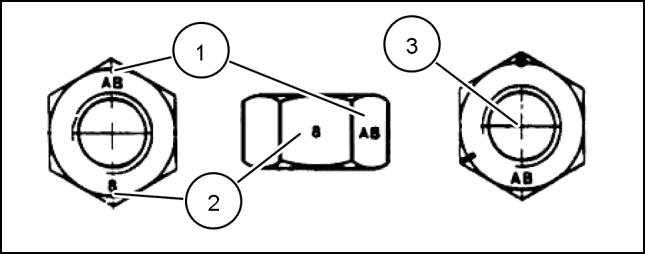
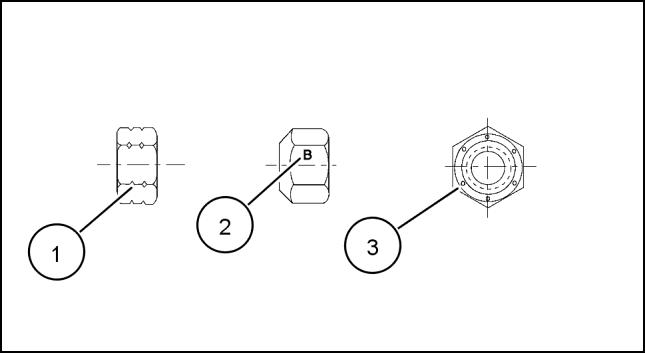
NOM. SIZE CLASS 8.8 BOLT and CLASS 8 NUT CLASS 10.9 BOLT and CLASS 10 NUT LOCKNUT CL.8 W/CL8.8 BOLT LOCKNUT CL.10 W/CL10.9 BOLT UNPLATED PLATED W/ZnCr UNPLATED PLATED W/ZnCr M4 2.4 N·m (21 lb in) 3.2 N·m (28 lb in) 3.5 N·m (31 lb in) 4.6 N·m (41 lb in) 2.2 N·m (19 lb in) 3.1 N·m (27 lb in) M5 4.9 N·m (43 lb in) 6.5 N·m (58 lb in) 7.0 N·m (62 lb in) 9.4 N·m (83 lb in) 4.4 N·m (39 lb in) 6.4 N·m (57 lb in) M6 8.3 N·m (73 lb in) 11 N·m (96 lb in) 12 N·m (105 lb in) 16 N·m (141 lb in) 7.5 N·m (66 lb in) 11 N·m (96 lb in) M8 20 N·m (179 lb in) 27 N·m (240 lb in) 29 N·m (257 lb in) 39 N·m (343 lb in) 18 N·m (163 lb in) 27 N·m (240 lb in) M10 40 N·m (30 lb ft) 54 N·m (40 lb ft) 57 N·m (42 lb ft) 77 N·m (56 lb ft) 37 N·m (27 lb ft) 53 N·m (39 lb ft) M12 70 N·m (52 lb ft) 93 N·m (69 lb ft) 100 N·m (74 lb ft) 134 N·m (98 lb ft) 63 N·m (47 lb ft) 91 N·m (67 lb ft) M16 174 N·m (128 lb ft) 231 N·m (171 lb ft) 248 N·m (183 lb ft) 331 N·m (244 lb ft) 158 N·m (116 lb ft) 226 N·m (167 lb ft) M20 350 N·m (259 lb ft) 467 N·m (345 lb ft) 484 N·m (357 lb ft) 645 N·m (476 lb ft) 318 N·m (235 lb ft) 440 N·m (325 lb ft) M24 607 N·m (447 lb ft) 809 N·m (597 lb ft) 838 N·m (618 lb ft) 1118 N·m (824 lb ft) 552 N·m (407 lb ft) IDENTIFICATION Metric Hex head and carriage bolts, classes 5.6 and up 20083680 1 1. Manufacturer's Identification 2. Property Class Metric Hex nuts and locknuts, classes 05 and up 20083681 2 84533057 09/08/2011 6
1. Manufacturer's Identification
2. Property Class
3. Clock Marking of Property Class and Manufacturer's Identification
i.e. marks 60 ° apart indicate Class 10 properties, and marks 120 ° apart indicate Class 8.
INCH NON-FLANGED HARDWARE
NOTE: For Imperial Units, 1/4 in and 5/16 in hardware torque specifications are shown in pound-inches.
in through 1 in hardware torque specifications are shown in pound-feet.
INTRODUCTION
(Optional),
NOMINAL SIZE SAE GRADE 5 BOLT and NUT SAE GRADE 8 BOLT and NUT LOCKNUT GrB W/ Gr5 BOLT LOCKNUT GrC W/ Gr8 BOLT UNPLATED or PLATED SILVER PLATED W/ZnCr GOLD UNPLATED or PLATED SILVER PLATED W/ZnCr GOLD 1/4 8 N·m (71 lb in) 11 N·m (97 lb in) 12 N·m (106 lb in) 16 N·m (142 lb in) 8.5 N·m (75 lb in) 12.2 N·m (109 lb in) 5/16 17 N·m (150 lb in) 23 N·m (204 lb in) 24 N·m (212 lb in) 32 N·m (283 lb in) 17.5 N·m (155 lb in) 25 N·m (220 lb in) 3/8 30 N·m (22 lb ft) 40 N·m (30 lb ft) 43 N·m (31 lb ft) 57 N·m (42 lb ft) 31 N·m (23 lb ft) 44 N·m (33 lb ft) 7/16 48 N·m (36 lb ft) 65 N·m (48 lb ft) 68 N·m (50 lb ft) 91 N·m (67 lb ft) 50 N·m (37 lb ft) 71 N·m (53 lb ft) 1/2 74 N·m (54 lb ft) 98 N·m (73 lb ft) 104 N·m (77 lb ft) 139 N·m (103 lb ft) 76 N·m (56 lb ft) 108 N·m (80 lb ft) 9/16 107 N·m (79 lb ft) 142 N·m (105 lb ft) 150 N·m (111 lb ft) 201 N·m (148 lb ft) 111 N·m (82 lb ft) 156 N·m (115 lb ft) 5/8 147 N·m (108 lb ft) 196 N·m (145 lb ft) 208 N·m (153 lb ft) 277 N·m (204 lb ft) 153 N·m (113 lb ft) 215 N·m (159 lb ft) 3/4 261 N·m (193 lb ft) 348 N·m (257 lb ft) 369 N·m (272 lb ft) 491 N·m (362 lb ft) 271 N·m (200 lb ft) 383 N·m (282 lb ft) 7/8 420 N·m (310 lb ft) 561 N·m (413 lb ft) 594 N·m (438 lb ft) 791 N·m (584 lb ft) 437 N·m (323 lb ft) 617 N·m (455 lb ft) 1 630 N·m (465 lb ft) 841 N·m (620 lb ft) 890 N·m (656 lb ft) 1187 N·m (875 lb ft) 654 N·m (483 lb ft) 924 N·m (681 lb ft)
3/8
84533057 09/08/2011 7
FLANGED HARDWARE NOMINAL SIZE SAE GRADE 5 BOLT and NUT SAE GRADE 8 BOLT and NUT LOCKNUT GrF W/ Gr5 BOLT LOCKNUT GrG W/ Gr8 BOLT UNPLATED or PLATED SILVER PLATED W/ZnCr GOLD UNPLATED or PLATED SILVER PLATED W/ZnCr GOLD 1/4 9 N·m (80 lb in) 12 N·m (106 lb in) 13 N·m (115 lb in) 17 N·m (150 lb in) 8 N·m (71 lb in) 12 N·m (106 lb in) 5/16 19 N·m (168 lb in) 25 N·m (221 lb in) 26 N·m (230 lb in) 35 N·m (310 lb in) 17 N·m (150 lb in) 24 N·m (212 lb in) 3/8 33 N·m (25 lb ft) 44 N·m (33 lb ft) 47 N·m (35 lb ft) 63 N·m (46 lb ft) 30 N·m (22 lb ft) 43 N·m (32 lb ft) 7/16 53 N·m (39 lb ft) 71 N·m (52 lb ft) 75 N·m (55 lb ft) 100 N·m (74 lb ft) 48 N·m (35 lb ft) 68 N·m (50 lb ft) 1/2 81 N·m (60 lb ft) 108 N·m (80 lb ft) 115 N·m (85 lb ft) 153 N·m (113 lb ft) 74 N·m (55 lb ft) 104 N·m (77 lb ft) 9/16 117 N·m (86 lb ft) 156 N·m (115 lb ft) 165 N·m (122 lb ft) 221 N·m (163 lb ft) 106 N·m (78 lb ft) 157 N·m (116 lb ft) 5/8 162 N·m (119 lb ft) 216 N·m (159 lb ft) 228 N·m (168 lb ft) 304 N·m (225 lb ft) 147 N·m (108 lb ft) 207 N·m (153 lb ft) 3/4 287 N·m (212 lb ft) 383 N·m (282 lb ft) 405 N·m (299 lb ft) 541 N·m (399 lb ft) 261 N·m (193 lb ft) 369 N·m (272 lb ft) 7/8 462 N·m (341 lb ft) 617 N·m (455 lb ft) 653 N·m (482 lb ft) 871 N·m (642 lb ft) 421 N·m (311 lb ft) 594 N·m (438 lb ft) 1 693 N·m (512 lb ft) 925 N·m (682 lb ft) 979 N·m (722 lb ft) 1305 N·m (963 lb ft) 631 N·m (465 lb ft) 890 N·m (656 lb ft)
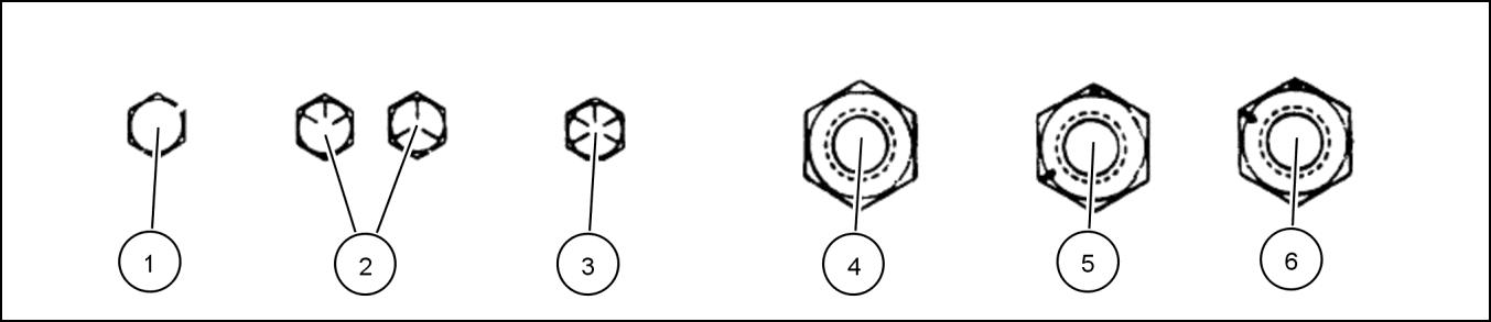
Inch Bolts and free-spinning nuts 20083682 3 Grade Marking Examples SAE Grade Identification 1 Grade 2 - No Marks 4 Grade 2 Nut - No Marks 2 Grade 5 - Three Marks 5 Grade 5 Nut - Marks 120 ° Apart 3 Grade 8 - Five Marks 6 Grade 8 Nut - Marks 60 ° Apart 84533057 09/08/2011 8
INTRODUCTION INCH
IDENTIFICATION
Inch Lock Nuts, All Metal (Three optional methods)
INTRODUCTION
Grade Identification 20090268 4 Grade Corner Marking Method (1) Flats Marking Method (2) Clock Marking Method (3) Grade A No Notches No Mark No Marks Grade B One Circumferential Notch Letter B Three Marks Grade C Two Circumferential Notches Letter C Six Marks 84533057 09/08/2011 9
Capacities
INTRODUCTION
System Metric U.S. Imperial 9.0 l engine Engine oil – no filter change 25 l 6.6 US gal 5.5 UK gal Engine oil– with filter change 25 l 6.6 US gal 5.5 UK gal Cooling system 26.5 l 7 US gal 5.8 UK gal Transmission/hydraulic system 172 l 45.5 US gal 38 UK gal Mechanical front drive 4 Pin – 100 mm (4 in) hub length standard axle* Differential 11.8 l 12.5 US qt (A) 21.6 UK pt Planetary (each) 1.4 l 4 Pin – 180 mm (7 in) hub length heavy duty axle* Differential 11.8 l 3 US pt 12.5 US qt 2.5 UK pt 20.8 UK pt Planetary (each) 3.3 l 7 US pt 5.8 UK pt 4 pin – 250 mm (10 in) hub length heavy duty class 5 axle Differential 15 l 15.8 US qt 26.4 UK pt Planetary (each) 6 l 12.7 US pt 10.5 UK pt Front PTO 3.05 l 3.2 US qt -DEF/ADBLUE® Tank 87 l 23 US gal 23.8 UK gal Fuel tank 636 l 168 US gal 140 UK gal * Pin quantity is determined by observing the wheel ends. 84533057 09/08/2011 10
SERVICE MANUAL
PNEUMATIC, ELECTRICAL, ELECTRONIC SYSTEMS T8.275 T8.300 T8.330 T8.360 T8.390 84533057 09/08/2011 A
HYDRAULIC,
Contents HYDRAULIC, PNEUMATIC, ELECTRICAL, ELECTRONIC
PRIMARY HYDRAULIC POWER SYSTEM..................................................................................A.10.A T8.275 , T8.300 , T8.330 , T8.360 , T8.390 PRIMARY HYDRAULIC POWER SYSTEM Electro-hydraulic remote valve A.10.C T8.275 , T8.300 , T8.330 , T8.360 , T8.390 PNEUMATIC SYSTEM A.20.A T8.275 , T8.300 , T8.330 , T8.360 , T8.390 ELECTRICAL POWER SYSTEM A.30.A T8.275 , T8.300 , T8.330 , T8.360 , T8.390 ELECTRONIC SYSTEM ................................................................... A.50.A T8.275 , T8.300 , T8.330 , T8.360 , T8.390 FAULT CODES ............................................................................. A.50.A T8.275 , T8.300 , T8.330 , T8.360 , T8.390 84533057 09/08/2011 A
SYSTEMS - A
PNEUMATIC, ELECTRICAL, ELECTRONIC
HYDRAULIC POWER
10.A T8.275 T8.300 T8.330 T8.360 T8.390 84533057 09/08/2011 A.10.A / 1
HYDRAULIC,
SYSTEMS - A PRIMARY
SYSTEM -
Contents HYDRAULIC, PNEUMATIC, ELECTRICAL, ELECTRONIC SYSTEMS - A PRIMARY HYDRAULIC POWER SYSTEM - 10.A TECHNICAL DATA Pressure/flow compensating (PFC) pump Torque 4 FUNCTIONAL DATA PRIMARY HYDRAULIC POWER SYSTEM Hydraulic schematic frame 01 6 Hydraulic symbol - Schematic components 9 Hydraulic symbol - Pressure control 15 Hydraulic symbol - Directional control 17 Hydraulic symbol - Composite 18 Hydraulic symbol - Flow control 21 Hydraulic symbol - Table of symbols 22 Power beyond Dynamic description 26 Hydraulic pump Dynamic description 28 Tandem gear pump Charge and lubrication - Component identification 38 Motor return Component identification.......................................................................................................................................39 Control valve Priority/Regulator valve - Dynamic description 40 Priority/Regulator valve - Exploded view 43 Priority/Regulator valve - Sectional view 45 Pressure/flow compensating (PFC) pump Dynamic description 47 Standard - Component identification 50 High flow - Component identification...................................................................................................................52 Dual flow - Component identification - Pump layout..........................................................................................54 SERVICE Hydraulic pump 84533057 09/08/2011 A.10.A / 2
Tandem gear pump Charge and lubrication - Pressure test.............................................................................56 Tandem gear pump Charge and lubrication - Remove 58 Tandem gear pump Charge and lubrication - Install 62 Suction screen Remove 65 Cleaning 70 Install 71 Pump drive Remove 75 Disassemble 77 Assemble 81 End play 86 Install 87 Control valve Priority/Regulator valve - Pressure test...............................................................................................................89 Priority/Regulator valve - Leakage test 90 Priority/Regulator valve - Adjust 93 Priority/Regulator valve - Remove 94 Priority/Regulator valve - Disassemble 97 Priority/Regulator valve - Assemble 101 Priority/Regulator valve - Install .........................................................................................................................104 Flow compensator - Adjust - Low pressure standby setting...........................................................................107 Flow compensator - Inspect ...............................................................................................................................109 Pressure/flow compensating (PFC) pump Standard - Flow test - At the remote couplers 110 Dual flow - Flow test - At the remote coupler 112 Standard - Flow test At the pump outlet 114 High flow - Flow test - At the pump outlet 117 Dual flow - Flow test - At the pump outlet 120 Pressure test - High pressure standby setting 123 Remove - Standard or high flow.........................................................................................................................124 Install - Standard and high flow..........................................................................................................................127 Dual flow - Remove 131 Dual flow - Install 133 84533057 09/08/2011 A.10.A / 3
HYDRAULIC, PNEUMATIC, ELECTRICAL, ELECTRONIC SYSTEMS - PRIMARY HYDRAULIC POWER SYSTEM
Pressure/flow compensating (PFC) pump - Torque
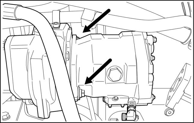
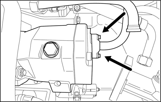
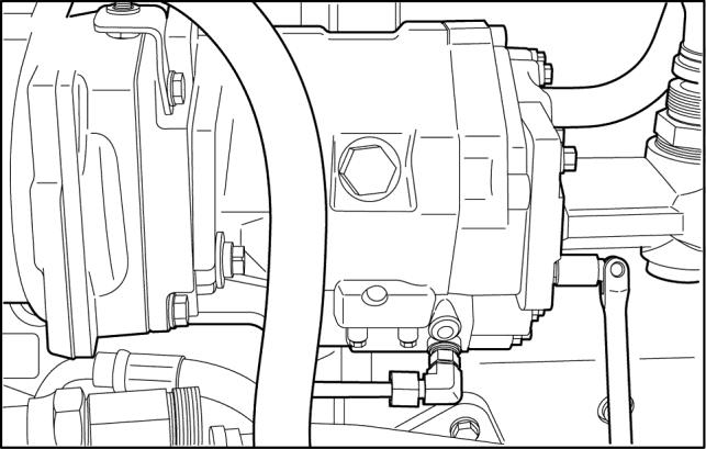
Component Nm Identification lb-ft Filter head retaining bolts 62 - 80 Nm RCPH11CCH433AAA 1 46 - 59 lb ft Pressure and flow compensating (PFC) pump split flange retaining bolts 40 - 60 Nm RCPH11CCH435AAA 2 30 - 44 lb ft Pressure and flow compensating (PFC) pump mounting bolts 62 - 80 Nm RCPH11CCH437AAA 3 46 - 59 lb ft 84533057 09/08/2011 A.10.A / 4
84533057 09/08/2011 A.10.A / 5
HYDRAULIC, PNEUMATIC, ELECTRICAL, ELECTRONIC SYSTEMS - PRIMARY HYDRAULIC POWER SYSTEM
HYDRAULIC, PNEUMATIC, ELECTRICAL, ELECTRONIC SYSTEMS - PRIMARY HYDRAULIC POWER SYSTEM


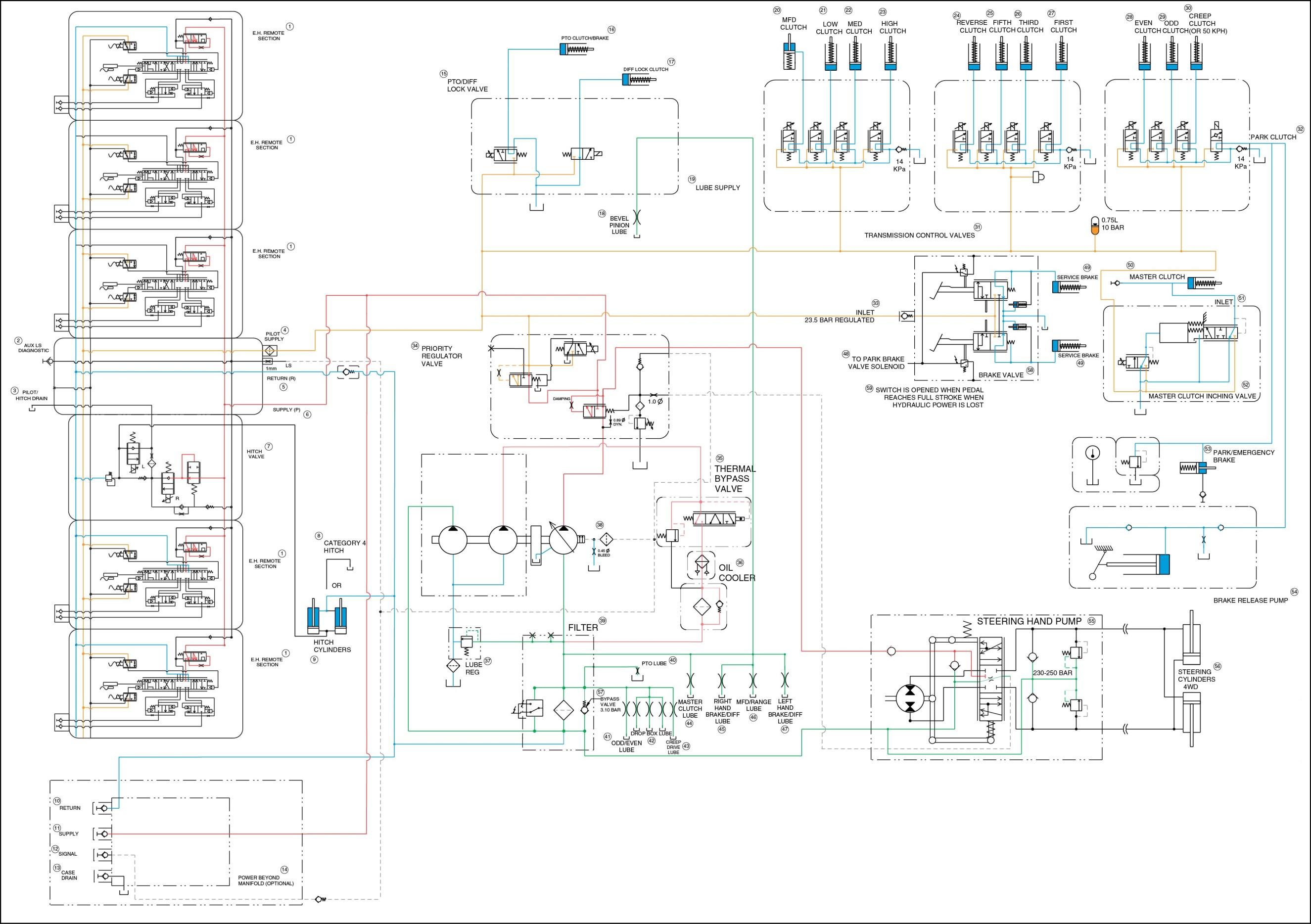
PRIMARY HYDRAULIC POWER SYSTEM - Hydraulic schematic frame 01
Hydraulic schematic 84414791
PFC PISTON PUMP
CHARGE LUBE/LUBE PUMP FLOW
REGULATED CIRCUIT PRESSURE
RETURN TO TANK/SUMP
OIL

1. Remote section 31. Transmission control valves 2. Load sense diagnostic 32. Park clutch 3. Pilot/hitch drain 33. Inlet regulator 4. Pilot supply 34. Priority regulator valve 5. Return 35. Thermal bypass valve 6. Supply 36. Oil cooler 7. Hitch valve 37. Lube regulator 8. Category 4 hitch 38. Piston pump 9. Hitch cylinders 39. Filter 10. Return 40. PTO lube 11. Supply 41. Odd/even lube 12. Signal 42. Drop box lube 13. Case drain 43. Creep drive lube 14. Power beyond 44. Master clutch lube 15. PTO/differential lock valve 45. Right brake/differential lube 16. PTO clutch/brake 46. MFD/range lube 17. Differential lock clutch 47. Left brake/differential lube 18. Bevel pinion lube 48. To park brake valve 19. Lube supply 49. Service brake 20. MFD clutch 50. Master clutch 21. Low clutch 51. Inlet 22. Medium clutch 52. Master clutch inching valve 23. Hitch clutch 53. Park/emergency brake 24. Reverse clutch 54. Brake release pump 25. Fifth clutch 55. Steering hand pump 26. Third clutch 56. Steering cylinders 27. First clutch 57. Bypass valve 28. Even clutch 58. Brake valve 29. Odd clutch 59. NOTE: Switch is opened when pedal reaches full stroke when hydraulic power is lost. 30. Creeper clutch 84533057 09/08/2011 A.10.A / 6
COOLER/FILTRATION, AUX CHARGE PUMP FLOW
RCIL11CCH300JAA 1 84533057 09/08/2011 A.10.A / 7
HYDRAULIC, PNEUMATIC, ELECTRICAL, ELECTRONIC SYSTEMS - PRIMARY HYDRAULIC POWER SYSTEM
HYDRAULIC, PNEUMATIC, ELECTRICAL, ELECTRONIC SYSTEMS - PRIMARY HYDRAULIC POWER SYSTEM 84533057 09/08/2011 A.10.A / 8
PRIMARY HYDRAULIC POWER SYSTEM - Hydraulic symbol -
Schematic components
Accurate diagrams of hydraulic circuits are essential to the technician who must repair them. The diagram shows how the components interact. The diagram shows how the system works, what each component should be doing and where the oil should be going so the technician can diagnose and repair the system.
There are two types of circuit diagrams:
• Cutaway circuit diagrams show the internal construction of the components as well as the flow paths. Using colors, shades or various patterns in the lines and passages, they show many different conditions of flow and pressure. Cutaway diagrams take considerably longer to produce because of their complexity.
• Schematic circuit diagrams, the “shorthand” system of the industry, are usually preferred for troubleshooting. A schematic diagram is made up of simple geometric symbols for the components and their controls and connections.
There are several systems of symbols used when making schematic diagrams:
• ISO – International Standards Organization
• ANSI – American National Standards Institute
• ASA – American Standards Association
• JIC – Joint Industry Conference
A combination of symbols from these systems are shown. There are differences between the symbol systems. There is enough similarity, however, so if you understand the symbols shown, you will be able to interpret other symbols as well.
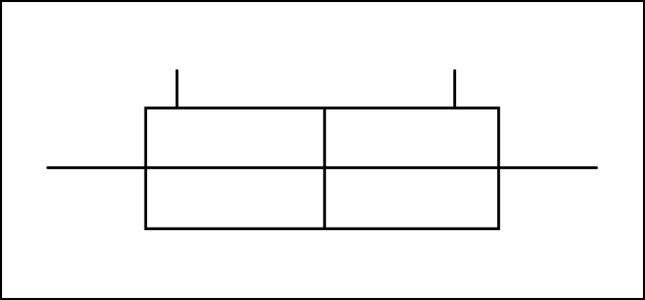
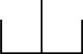
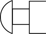
Reservoirs
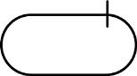
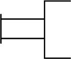
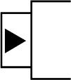
A rectangle with the top removed represents a vented reservoir (A) A rectangle with the top in place represents a pressurized reservoir (B)
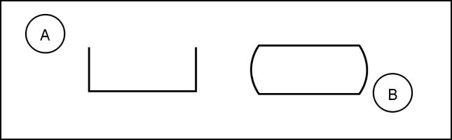


There are other schematic diagrams that show a slightly different version of a pressurized reservoir, but the symbols are similar and easily recognized. An oval with a short line on top or a rectangle with curved sides represents a reservoir that is pressurized.
Lines connected to the reservoir usually are drawn from the top, regardless of where the actual connection is. This symbol shows a line which returns fluid above the level in the reservoir. If the hydraulic line returns fluid below the level in the reservoir, it is drawn all the way to the bottom of the symbol.
HYDRAULIC, PNEUMATIC, ELECTRICAL, ELECTRONIC SYSTEMS - PRIMARY HYDRAULIC POWER SYSTEM
RCIL07CCH025AAA 1 RCIL07CCH027AAA 2 RCIL07CCH030AAA 3 RCIL07CCH032AAA 4 84533057 09/08/2011 A.10.A / 9
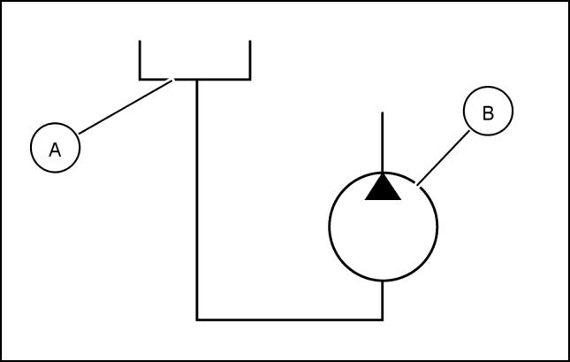
A hydraulic line connected to the bottom of the reservoir may be drawn from the bottom of the symbol if the bottom connection is essential to the systems operation. If the pump inlet (B) must be charged or flooded with fluid above the inlet port, the reservoir symbol (A) appears above the pump symbol, and the suction line is drawn out of the bottom of the reservoir symbol.
Every system reservoir has at least two hydraulic lines connected to it, and some may have many more. Often the components that are connected to the reservoir are spread all over the schematic. Rather than multiplying lines all over the schematic, individual reservoir symbols are drawn close to the components. The reservoir is usually the only component symbol pictured more than once on a diagram.
Lines, tubes and hoses
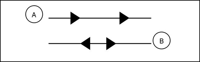
A hydraulic line, tube, hose or any conductor that carries the fluid between components is shown as a line. A working line, such as an inlet pressure or return, is shown as a solid line.
RCIL07CCH033AAA 5 RCIL07CCH124AAA 6
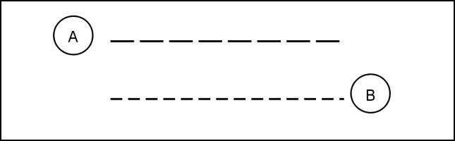
Working lines with arrows show direction of flow. In the first example (A), fluid flows in one direction only; in the second example (B), fluid can flow in both directions. Pilot or control lines (A) are broken into long dashes. Drain lines (B) for leakage oil are broken into short dashes.
RCIL07CCH034AAA 7
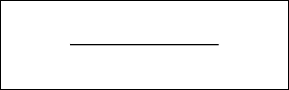
A flexible line is shown as an arc between two dots and is always represented by a solid line.


RCIL07CCH035AAA 8
RCIL07CCH036AAA 9
RCIL07CCH026AAA 10
ELECTRONIC SYSTEMS - PRIMARY HYDRAULIC POWER
HYDRAULIC, PNEUMATIC, ELECTRICAL,
SYSTEM
84533057 09/08/2011 A.10.A / 10
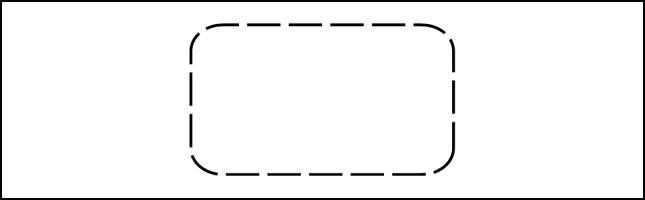
An enclosure outline indicates that there are several symbols that make up a component assembly such as a valve or a valve stack. The enclosure outline is rectangular and is broken with dashes on all sides.
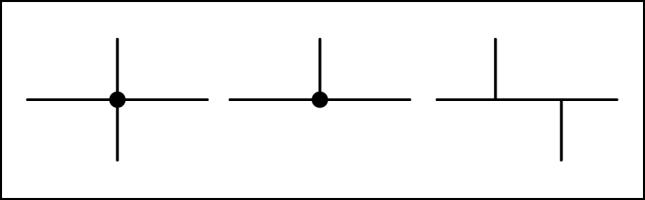
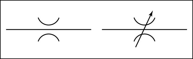
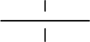
Lines between components are drawn differently when they are crossing or connected. There are lines that cross other lines but are not connected. There are several ways to show crossing lines which are not connected.
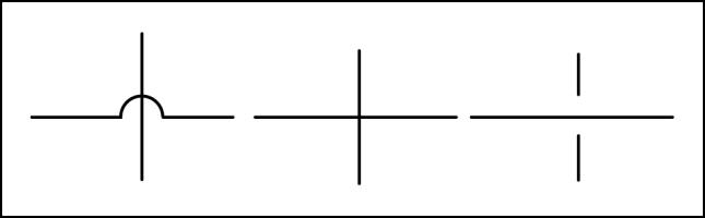
Lines that are connected are shown with a dot that represents the connection or shown as a tee connection. The dot connection is the most commonly used when drawing schematic diagrams.
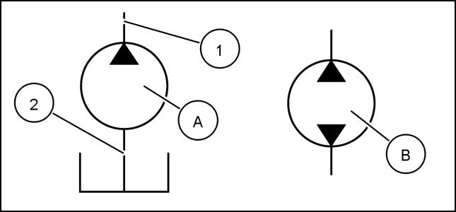
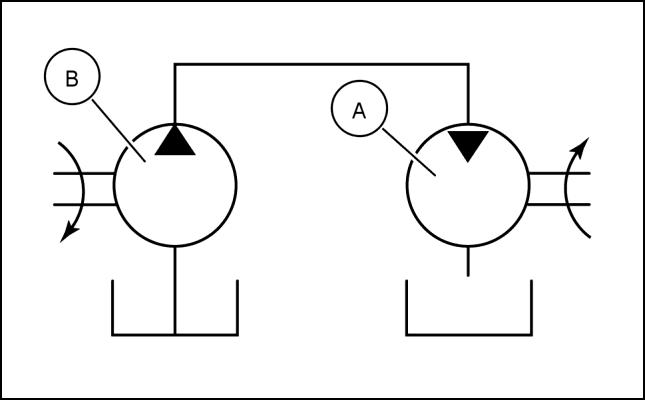
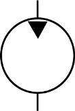
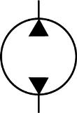
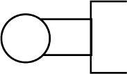
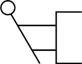
Pumps
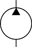
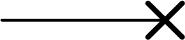
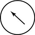
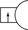
There are many basic pump designs. A simple fixed displacement pump (A) is shown as a circle with a solid arrow that pointing outward. The arrow points in the direction that the fluid flows. If the pump is reversible (B) or designed to pump in either direction, the symbol has two arrows which point in opposite directions. The pump normally has a pressure port and line (1) from which pressurized fluid is discharged and a suction port and line (2) into which fluid is drawn from the reservoir.
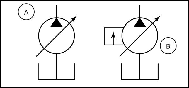
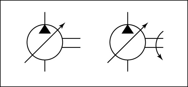
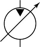
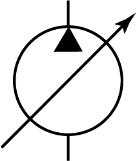
A variable displacement pump (A) is shown by an arrow drawn through the pump symbol at a 45 degree angle. A variable displacement, pressure compensated pump (B) is shown by a small box with an arrow, added to the side of the pump symbol.
RCIL07CCH048AAA 14
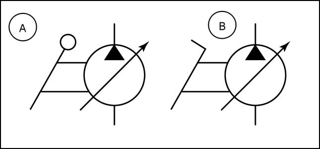
If the pump is controlled by a lever (A) or a pedal (B), the appropriate symbol is added to the side of the pump.
RCIL07CCH040AAA 15
RCIL07CCH041AAA 16
HYDRAULIC, PNEUMATIC, ELECTRICAL, ELECTRONIC SYSTEMS - PRIMARY HYDRAULIC POWER SYSTEM
RCIL07CCH028AAA 11 RCIL07CCH038AAA 12 RCIL07CCH047AAA 13
84533057 09/08/2011 A.10.A / 11
HYDRAULIC, PNEUMATIC, ELECTRICAL, ELECTRONIC SYSTEMS - PRIMARY HYDRAULIC POWER SYSTEM
A drive shaft is shown as two short parallel lines extending from the side of the pump. A curved arrow, if present, on the drive shaft indicates the direction of rotation.
RCIL07CCH049AAA 17
Motors
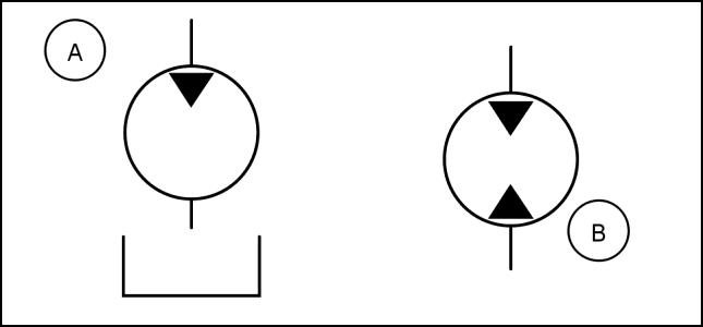
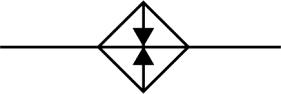
Motor symbols are circles with solid black arrows, which point in the opposite direction of a pump’s arrow, to show the motor as a receiver of fluid. One arrow is used for non-reversible motors (A); and two arrows are used for reversible motors (B)
RCIL07CCH051AAA 18
A simple schematic diagram is shown of a hydraulic motor (A) connected to a hydraulic pump (B)
RCIL07CCH046AAA 19
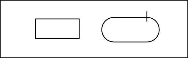
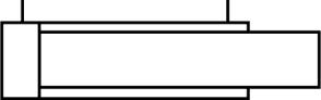
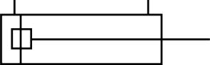
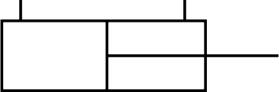
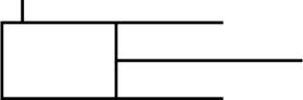
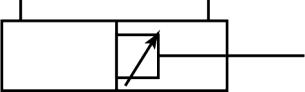
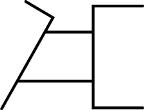
Cylinders
A cylinder is a simple rectangle (A) representing the barrel. The piston and rod are represented by a tee (B), inserted into the rectangle. The symbol can be drawn in any position.
RCIL07CCH055AAA 20
84533057 09/08/2011 A.10.A / 12
If the cylinder is single-acting (A), there is only one port shown on the end of the cylinder that receives pressurized fluid. The opposite end of the cylinder is left open. Both ends are closed on a double-acting cylinder (B), and two ports are shown.
A double rod end cylinder has a rod extending from each end of the rectangle.
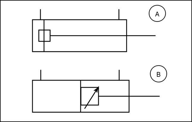
Some cylinders have cushions built into them. The cushion slows the movement of the piston as it nears the end of its stroke. Cylinder cushions are shown as a smaller rectangle (A) on the piston. If the cushion has an adjustable orifice, a slanted arrow is drawn at 45 degrees (B) across the symbol.
Accessories
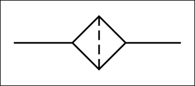
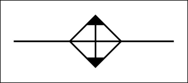
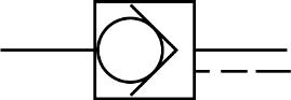
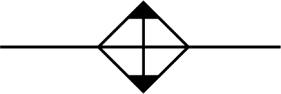
Filters, strainers and heat exchangers are represented as squares that are turned 45 degrees and have the port connections at the corners.
A dotted line perpendicular to the flow line represent a filter, strainer or screen.
HYDRAULIC, PNEUMATIC, ELECTRICAL, ELECTRONIC SYSTEMS - PRIMARY HYDRAULIC POWER SYSTEM
RCIL07CCH054AAA 21 RCIL07CCH057AAA 22 RCIL07CCH126AAA 23
RCIL07CCH080AAA 24 84533057 09/08/2011 A.10.A / 13
HYDRAULIC, PNEUMATIC, ELECTRICAL, ELECTRONIC SYSTEMS - PRIMARY HYDRAULIC POWER SYSTEM
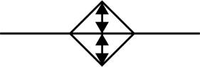
A solid line perpendicular to the flow with solid arrows pointing outward represents a cooler.
The symbol for a heater is like the symbol for a cooler, except the solid arrows point inward.
Two sets of arrows pointing inward and outward represents a temperature control unit
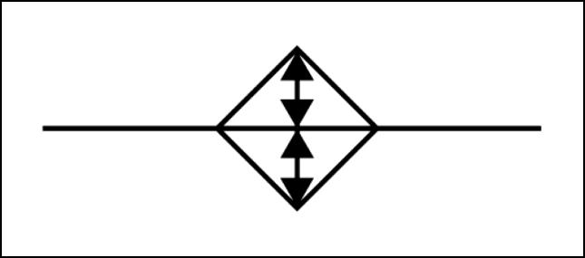
The solid arrows point in the direction that heat is dissipated. Or in the case of the control unit, they show that heat can be regulated.
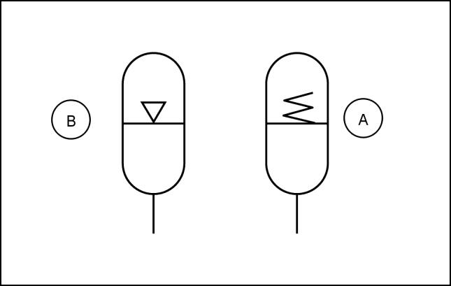
An oval with details inside represents an accumulator. The details explain what type of accumulator it is: spring loaded (A), gas charged (B), or other features.
The divider line indicates there is a separator between the charge and the fluid. A hollow arrow indicates gas.
A spring indicates that the accumulator is spring-loaded.
Reference:
PRIMARY HYDRAULIC POWER SYSTEM - Hydraulic symbol - Pressure control (A.10.A)
PRIMARY HYDRAULIC POWER SYSTEM - Hydraulic symbol - Directional control (A.10.A)
PRIMARY HYDRAULIC POWER SYSTEM - Hydraulic symbol - Composite (A.10.A)
PRIMARY HYDRAULIC POWER SYSTEM - Hydraulic symbol - Flow control (A.10.A)
PRIMARY HYDRAULIC POWER SYSTEM - Hydraulic symbol - Table of symbols (A.10.A)
RCIL07CCH081AAA 25 RCIL07CCH118AAA 26 RCIL07CCH119AAA 27 RCIL07CCH130AAA 28
84533057 09/08/2011 A.10.A / 14
PRIMARY HYDRAULIC POWER SYSTEM - Hydraulic symbolPressure control
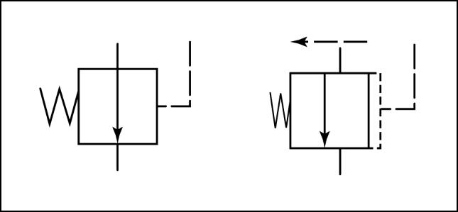
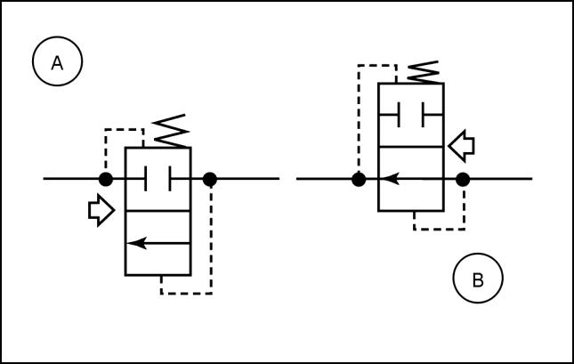
The basic valve symbol is a square (which is called an envelope) with external port connections and an arrow inside to show the fluid passage and direction of flow. The valve usually operates by balancing fluid pressure against a spring, so a spring is shown on one side of the symbol and a pilot pressure line on the other side.
Normally closed valve
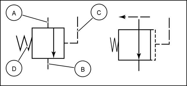
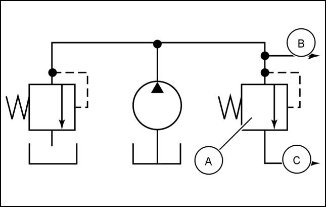
A normally closed valve, such as a relief or sequence valve, is shown with an arrow offset from the ports [inlet (A), outlet (B)] toward the pilot pressure line (C) side of the square. The spring (D) holds the valve closed until the pilot line pressure is greater than the spring pressure. Mentally visualize a build up of pressure in the pilot line and the envelope moving over, compressing the spring. Fluid can now flow through the valve.
Normally open valve
A normally open valve is shown with the arrow connecting the inlet and outlet ports. It closes when pressure overcomes spring force. Mentally visualize a build up of pressure in the pilot line and the envelope moving over, compressing the spring. Fluid flow through the valve is now blocked.
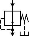
Relief valve
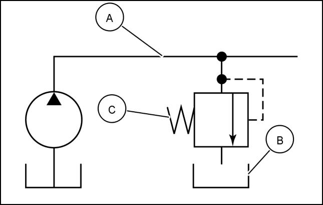
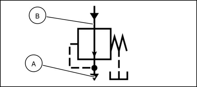
A relief valve is shown as a normally closed symbol connected between the pressure line (A) and the reservoir (B). The flow direction arrow points away from the pressure line port and toward the reservoir. This graphically represents how a relief valve operates. When pressure in the system overcomes the valve spring (C), flow is from the pressure line through the relief valve to the reservoir.
HYDRAULIC, PNEUMATIC, ELECTRICAL, ELECTRONIC SYSTEMS - PRIMARY HYDRAULIC POWER SYSTEM
RCIL07CCH059AAA 1
RCIL07CCH060AAA 2
3 84533057 09/08/2011 A.10.A / 15
RCIL07CCH061AAA
HYDRAULIC, PNEUMATIC, ELECTRICAL, ELECTRONIC SYSTEMS - PRIMARY HYDRAULIC POWER SYSTEM
Pressure reducing valve
A pressure reducing valve is shown as a normally open symbol in a pressure line. This valve works opposite of a relief valve, since it senses outlet pressure (A) versus inlet pressure (B). As the outlet pressure builds, it works against a predetermined spring force. As the spring force is overcome, flow through the valve is reduced or shut off.
Sequence valve
The normally closed symbol is also used for a sequence valve (A). The inlet port is connected to a primary cylinder (B) and the outlet port to the secondary cylinder line (C). When the piston in the primary cylinder reaches the end of its stroke, the pressure in the supply line increases. The sequence valve is also connected to the supply line and also feels the increase in pressure. As pressure increases, the envelope and directional flow arrow move over, connecting the inlet and outlet ports allowing fluid to flow to the secondary cylinder.
Reference:
PRIMARY HYDRAULIC POWER SYSTEM - Hydraulic symbol - Directional control (A.10.A)
PRIMARY HYDRAULIC POWER SYSTEM - Hydraulic symbol - Composite (A.10.A)
PRIMARY HYDRAULIC POWER SYSTEM - Hydraulic symbol - Flow control (A.10.A)
PRIMARY HYDRAULIC POWER SYSTEM - Hydraulic symbol - Table of symbols (A.10.A)
RCIL07CCH063AAA 4
RCIL07CCH062AAA 5
84533057 09/08/2011 A.10.A / 16
PRIMARY HYDRAULIC POWER SYSTEM - Hydraulic symbolDirectional control
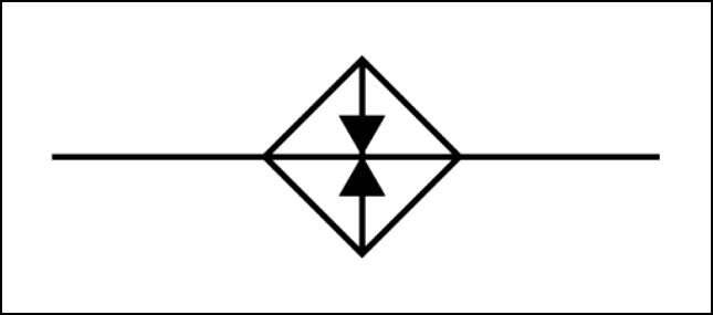
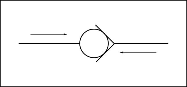
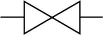
One way valve
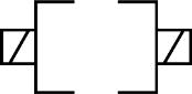
A simple ball check valve is shown. When fluid pressure is exerted on the left side of the ball, the ball is forced into the “V” and no fluid can flow though the valve. When fluid pressure is applied to the right side of the ball, the ball moves away from the “V” and fluid can flow through the valve.
RCIL07CCH066AAA 1
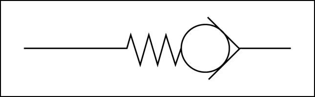
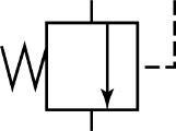
Bypass valve
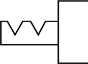
A bypass valve is shown as a one-way valve with a spring on the ball end of the symbol. Pressurized flow is necessary to overcome the spring force and allow flow around the ball.
RCIL07CCH067AAA 2
Reference:
PRIMARY HYDRAULIC POWER SYSTEM - Hydraulic symbol - Composite (A.10.A)
PRIMARY HYDRAULIC POWER SYSTEM - Hydraulic symbol - Flow control (A.10.A)
PRIMARY HYDRAULIC POWER SYSTEM - Hydraulic symbol - Table of symbols (A.10.A)
HYDRAULIC, PNEUMATIC, ELECTRICAL, ELECTRONIC SYSTEMS - PRIMARY HYDRAULIC POWER SYSTEM
84533057 09/08/2011 A 10.A / 17
PRIMARY HYDRAULIC POWER SYSTEM - Hydraulic symbolComposite
One way valve
A more complex one-way valve is shown. This directional control symbol uses multiple envelopes with a separate envelope for each valve position. Within each envelope, arrows show the flow paths when the valve is shifted to that position.
NOTE: All port connections are made to the envelope which shows the neutral condition of the valve.
The left symbol (A) a one-way valve in the closed position. Mentally visualize a build up of pressure on the right side of the valve symbol (B) to enable free flow through the valve.
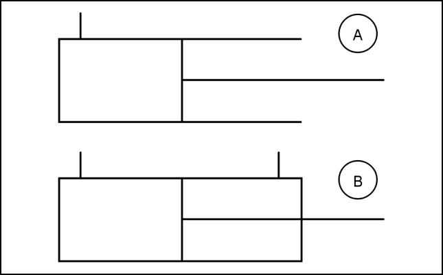
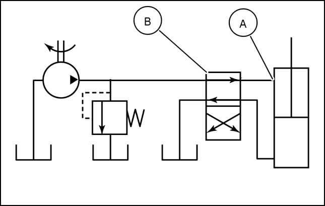
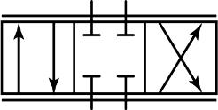
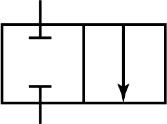
Two position valve
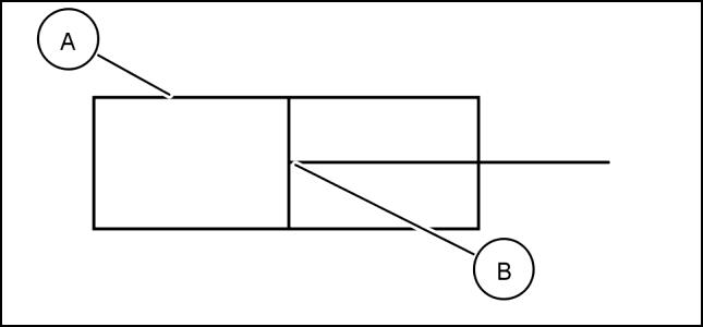
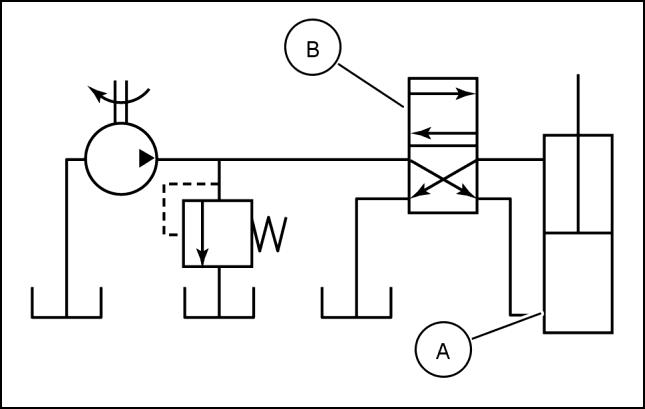
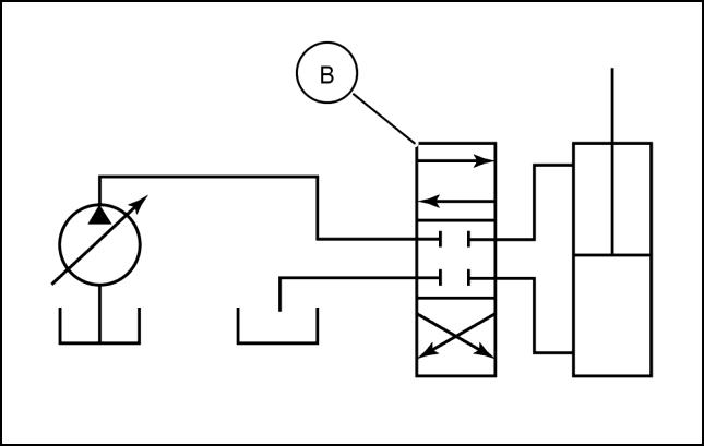
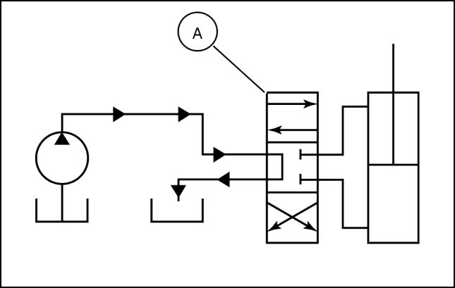
Two envelopes (representing the spool) indicate a two position valve. Each envelopes shows the flow conditions for its position. This simple schematic shows fluid supplied to the rod end of the cylinder (A) from the control valve (B) Return flow is from the piston end of the cylinder through the control valve to tank.
RCIL07CCH072AAA 1
Mentally visualize the directional control valve shifted to the other position. Pressurized fluid is supplied to the piston end of the cylinder (A) from the control valve (B), and return fluid flows from the rod end of the cylinder through the control valve to tank.
RCIL07CCH073AAA 2
RCIL07CCH074AAA 3
HYDRAULIC, PNEUMATIC, ELECTRICAL, ELECTRONIC SYSTEMS - PRIMARY HYDRAULIC POWER SYSTEM
84533057 09/08/2011 A.10.A / 18
HYDRAULIC, PNEUMATIC, ELECTRICAL, ELECTRONIC SYSTEMS - PRIMARY HYDRAULIC POWER SYSTEM
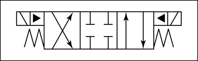
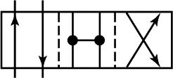
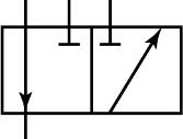
Three position valve
Three position valves have a centered (neutral) position. The centered position can be either open or closed to flow. The open center (A) is usually used with a fixed displacement pump, while the closed center (B) is usually used with a variable displacement pump.
Actuating controls
Valve spools are controlled by pedals (A), levers (B), pilot fluid (C), electric solenoids (D), etc., which are called actuating controls. These actuating controls are shown by symbols placed on the ends of the envelopes.
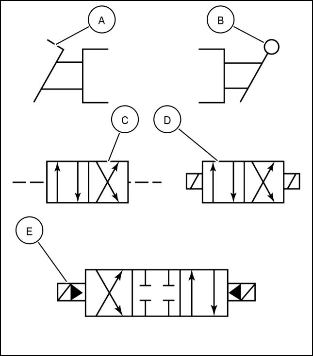
This symbol (E) is used when a solenoid is controlled with internal pilot assist pressure.
 RCIL07CCH068AAA 4
RCIL07CCH069AAA 5
RCIL07CCH068AAA 4
RCIL07CCH069AAA 5
84533057 09/08/2011 A.10.A / 19
RCIL07CCH017BAA 6
HYDRAULIC, PNEUMATIC, ELECTRICAL, ELECTRONIC SYSTEMS - PRIMARY HYDRAULIC POWER SYSTEM
To show that a valve is spring-centered, a spring symbol is placed at each end of the envelope. This symbol shows that a solenoid and pilot pressure assist are required to overcome spring force to move the valve spool.
Reference: PRIMARY HYDRAULIC POWER SYSTEM - Hydraulic symbol - Flow control (A.10.A)
PRIMARY HYDRAULIC POWER SYSTEM - Hydraulic symbol - Table of symbols (A.10.A)
RCIL07CCH070AAA 7
84533057 09/08/2011 A.10.A / 20
PRIMARY HYDRAULIC POWER SYSTEM - Hydraulic symbol - Flow control
Restrictors
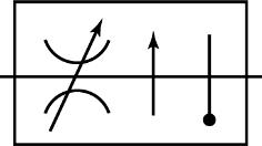
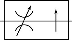
The basic flow control symbol is a restrictor. If the restrictor is adjustable, a slanted arrow is drawn across the symbol. The restrictor could be a special fitting with a small hole in it or a small drilled passageway within a valve. An adjustable restrictor acts like a faucet: adjusting the restriction regulates flow. Restrictors are used to meter and bleed circuits.
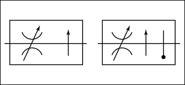
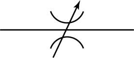
Adjustable restrictors can be pressure-compensated: the size of the opening in the restrictor changes with increases and decreases in pressure. A perpendicular arrow indicates pressure compensation. If the restrictor has both pressure and temperature compensation, the symbol for a thermometer is added.
Reference: PRIMARY HYDRAULIC POWER SYSTEM - Hydraulic symbol - Table of symbols (A.10.A)
HYDRAULIC, PNEUMATIC, ELECTRICAL, ELECTRONIC SYSTEMS - PRIMARY HYDRAULIC POWER SYSTEM
RCIL07CCH075AAA 1 RCIL07CCH078AAA 2
84533057 09/08/2011 A.10.A / 21
HYDRAULIC, PNEUMATIC, ELECTRICAL, ELECTRONIC SYSTEMS - PRIMARY HYDRAULIC POWER SYSTEM
PRIMARY HYDRAULIC POWER SYSTEM - Hydraulic symbol - Table of symbols

Line and line functions


Solid line - main line
Dashed line - pilot line
Dotted line - exhaust or drain line
Enclosure outline
Lines crossing Lines joining
Lines crossing
Gaseous direction of flow
Mechanical devices
Connections (two parallel lines) for shafts, levers, etc.
Spring Pumps and motors
Pump, fixed displacement
Pressure compensated, variable displacement pump
Motor, fixed displacement
Oscillator
Reservoirs
Liquid direction of flow
Flexible line
Variable component (arrow intersects symbol at 45 °)


Pump, variable displacement
Fixed displacement pump (bidirectional flow)
Motor, variable displacement
84533057 09/08/2011 A.10.A / 22
HYDRAULIC, PNEUMATIC, ELECTRICAL, ELECTRONIC SYSTEMS - PRIMARY HYDRAULIC POWER SYSTEM

Reservoir, open to atmosphere
Return line to reservoir below fluid level
Cylinders
Single acting
Double acting. double rod end
Single rod end, adjustable cushion, rod end only
Valves
Check valve
On/Off manual shut off valve
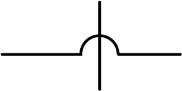
2 position, 4 way open center, crossover valve
Pressure relief valve
Pressurized reservoir
Return line to reservoir above fluid level

Double acting, single rod end


Single rod end, fixed cushion both ends
Differential cylinder
Pilot-operated check valve
Regulating or selector valves
Non-adjustable restrictor valve
Valve capable of infinite positioning (indicated by horizontal lines parallel to the envelope)


Pressure reducing valve
Adjustable restrictor valve
2 position, 2
valve 2 position, 3 way valve 2 position, 4 way valve 3 position, 4 way valve
way
84533057 09/08/2011 A.10.A / 23
HYDRAULIC, PNEUMATIC, ELECTRICAL, ELECTRONIC SYSTEMS - PRIMARY HYDRAULIC POWER SYSTEM
Adjustable restrictor, pressure compensated
Valve actuators
Adjustable restrictor, temperature and pressure compensated
Solenoid Detent


Spring Manual
Push button Lever
Pedal
Pressure compensated
Mechanical
Pilot pressure, remote supply
Liquid supply
Accessories
Filter Cooler
Heater
Accumulator (hydropneumatic
Station or test point
Temperature controller

Reversing motor

Pressure indicator

84533057 09/08/2011 A.10.A / 24