
Komatsu Wh609-1, Wh613-1, Wh713-1, Wh714-1, Wh714h-1, Wh716-1 Handler Service Manual
PLEASE CLICK HERE
Then back to the site.
At the bottom of the page,
Then get more free information
Komatsu Wh609-1, Wh613-1, Wh713-1, Wh714-1, Wh714h-1, Wh716-1 Handler Service Manual
Power coupling
Transmission
Four-Wheel Drive (4WD) system
Front axle system
Rear axle system
Power Take-Off (PTO)
Komatsu Wh609-1, Wh613-1, Wh713-1, Wh714-1, Wh714h-1, Wh716-1 Handler Service Manual
Brakes and controls
Hydraulic systems
Pneumatic system
Hitches, drawbars, and implement couplings
Steering
Wheels
Cab climate control
Electrical systems
Platform, cab, bodywork, and decals
Electrical Schematic
Hydraulic Schematic
WH6 - WH7 00-1 CONTENTS CONTENTS Pagina 10.STRUCTURE AND FUNCTION ......................................................................................10-1 20. TESTING AND ADJUSTING ...........................................................................................20-1 30. DISASSEMBLY AND ASSEMBLY .................................................................................30-1 90. OTHER ..........90-1
PAGE INTENTIONALLY LEFT BLANK
REVISED PAGES
The affected pages are indicated by the use of the following marks. It is requested that necessary actions be taken to these pages according to table below.
MarkIndicationAction required
Q Page to be newlyAdd
q Page to be replacedReplace
( ) Page to be deleteDiscard
Pages having no marks are those previously revised or made additions.
WH6 - WH7
REVISED PAGES
00-3
MarkPage Time of revision MarkPage Time of revision MarkPage Time of revision MarkPage Time of revision MarkPage Time of revision 00-1 00-2 00-3 00-4 00-5 00-6 00-7 00-8 00-9 00-10 00-11 00-12 00-13 00-14 00-15 00-16 00-17 00-18 00-19 00-20 00-21 00-22 00-23 00-24 10-1 10-2 10-3 10-4 10-5 10-6 10-7 10-8 10-9 10-10 10-11 10-12 10-13 10-14 10-15 10-16 10-17 10-18 10-19 10-20 10-21 10-22 10-23 10-24 10-25 10-26 10-27 10-28 10-29 10-30 10-31 10-32 10-33 10-34 10-35 10-36 10-37 10-38 10-39 10-40 10-41 10-42 10-43 10-44 10-45 10-46 10-47 10-48 10-49 10-50 10-51 10-52 10-53 10-54 10-55 10-56 10-57 10-58 10-59 10-60 10-61 10-62 10-63 10-64 10-65 10-66 10-67 10-68 10-69 10-70 10-71 10-72 10-73 10-74 10-75 10-76 10-77 10-78 10-79 10-80 10-81 10-82 10-83 10-84 10-85 10-86 10-87 10-88 20-1 20-2 20-3 20-4 20-5 20-6 20-7 20-8 20-9 20-10 20-11 20-12 20-13 20-14 20-15 20-16 20-17 20-18 20-19 20-20 20-21 20-22 20-23 20-24 20-25 20-26 20-27 20-28 20-29 20-30 20-31 20-32 20-33 20-34 20-35 20-36 20-37 20-38 20-39 20-40 20-41 20-42 20-43 20-44 20-45 20-46 20-47 20-48 20-49 20-50 20-51 20-52 20-53 20-54 20-55 20-56 20-57 20-58 20-59 20-60 20-61 20-62 20-63 20-64 20-65 20-66 20-67 20-68 20-69 20-70 20-71 20-72 20-73 20-74 20-75 20-76 20-77 20-78 20-79 20-80 20-81 20-82 20-83 20-84 20-85 20-86 20-87 20-88 20-89 20-90 20-91 20-92 20-93 20-94 20-95 20-96 20-97 20-98
WH6 - WH7 00-4 REVISED PAGES MarkPage Time of revision MarkPage Time of revision MarkPage Time of revision MarkPage Time of revision MarkPage Time of revision 20-99 20-100 20-101 20-102 20-103 20-104 20-105 20-106 20-107 20-108 20-109 20-110 30-1 30-2 30-3 30-4 30-5 30-6 30-7 30-8 30-9 30-10 30-11 30-12 30-13 30-14 30-15 30-16 30-17 30-18 30-19 30-20 30-21 30-22 30-23 30-24 30-25 30-26 30-27 30-28 30-29 30-30 30-31 30-32 30-33 30-34 30-35 30-36 30-37 30-38 30-39 30-40 30-41 30-42 30-43 30-44 30-45 30-46 30-47 30-48 30-49 30-50 30-51 30-52 30-53 30-54 30-55 30-56 30-57 30-58 30-59 30-60 30-61 30-62 30-63 30-64 30-65 30-66 30-67 30-68 30-69 30-70 30-71 30-72 30-73 30-74 30-75 30-76 30-77 30-78 30-79 30-80 30-81 30-82 30-83 30-84 30-85 30-86 30-87 30-88 30-89 30-90 30-91 30-92 30-93 30-94 30-95 30-96 30-97 30-98 30-99 30-100 30-101 30-102 30-103 30-104 30-105 30-106 30-107 30-108 30-109 30-110 30-111 30-112 30-113 30-114 30-115 30-116 30-117 30-118 30-119 30-120 30-121 30-122 30-123 30-124 30-125 30-126 30-127 30-128 30-129 30-130 30-131 30-132 30-133 30-134 30-135 30-136 30-137 30-138 30-139 30-140 30-141 30-142 30-143 30-144 30-145 30-146 30-147 30-148 30-149 30-150 30-151 30-152 30-153 30-154 30-155 30-156 30-157 30-158 30-159 30-160 30-161 30-162 30-163 30-164 30-165 30-166 30-167 30-168 30-169 30-170 30-171 30-172 30-173 30-174 30-175 30-176 30-177 30-178 30-179 30-180 30-181 30-182 30-183 30-184 30-185 30-186 30-187 30-188 30-189 30-190 30-191 30-192 30-193 30-194 30-195 30-196 30-197 30-198 30-199 30-200 30-201 30-202 30-203 30-204 30-205 30-206 30-207 30-208 30-209 30-210 30-211 30-212 30-213 30-214 30-215 30-216 30-217 30-218 30-219 30-220 30-221 30-222 30-223 30-224 30-225 30-226 30-227 30-228 30-229 30-230 30-231 30-232 30-233 30-234 30-235 30-236 30-237 30-238 30-239 30-240 30-241 30-242 30-243 30-244 30-245 30-246 30-247 30-248 30-249 30-250 30-251 30-252 30-253 30-254 30-255 30-256 30-257 30-258 30-259 30-260 30-261 30-262 30-263 30-264 30-265 30-266 30-267 30-268 30-269 30-270 30-271 30-272 30-273 30-274 30-275 30-276 30-277 30-278 30-279 30-280 30-281 30-282 30-283 30-284 90-1 90-2 90-3 90-4 90-5 90-6
kIMPORTANT SAFETY NOTICE
Proper service and repair is extremely important for the safe operation of your machine. The service and repair techniques recommended by Komatsu Utility and describe in this manual are both effective and safe methods of operation. Some of these operations require the use of tools specially designed by Komatsu Utility for the purpose.
To prevent injury to workers, the symbol k is used to mark safety precautions in this manual. The cautions accompanying these symbols should always be carefully followed. If any danger arises or may possibly arise, first consider safety, and take necessary steps to face.
kSAFETY
GENERAL PRECAUTIONS
Mistakes in operation extremely dangerous. Read all the Operation and Maintenance Manual carefully BEFORE operating the machine.
1.Before carrying out any greasing or repairs, read all the precautions written on the decals which are suck on the machine.
2.When carrying out any operation, always wear safety shoes and helmet. Do not wear loose work clothes, or clothes with buttons missing.
•Always wear safety glasses when hitting parts with a hammer.
•Always wear safety glasses when grinding parts with a grinder, etc.
3.If welding repairs are needed, always have a trained, experienced welder carry out the work. When carrying out welding work, always wear welding gloves, apron, glasses, cap and other clothes suited for welding work.
4.When carrying out any operation with two or more workers, always agree on the operating procedure before starting. Always inform your fellow workers before starting any step of the operation. Before starting work, hang UNDER REPAIR signs on the controls in the operator’s compartment.
5.Keep all tools in good condition and learn the correct way to use them.
6.Decide a place in the repair workshop to keep tools and removed parts. Always keep the tools and parts in their correct places. Always keep the work area clean and make sure that there is no dirt or oil on the floor. Smoke only in the areas provided for smoking. Never smoke while working.
PREPARATIONS FOR WORK
7.Before adding or making any repairs, park the machine on hard, level ground, and block the wheels to prevent the machine from moving.
8.Before starting work, lower outrigger, bucket or any other work equipment to the ground. If this is not possible, use blocks to prevent the work equipment from falling down. In addition, be sure to lock all the control levers and hang warning sign on them.
9.When disassembling or assembling, support the machine with blocks, jacks or stands before starting work.
10.Remove all mud and oil from the steps or other places used to get on and off the machine. Always use the handrails, ladders or steps when getting on or off the machine. Never jump on or off the machine. If it is impossible to use the handrails, ladders or steps, use a stand to provide safe footing.
PRECAUTIONS DURING WORK
11.When removing the oil filler cap, drain plug or hydraulic pressure measuring plugs, loosen them slowly to prevent the oil from spurting out. Before disconnecting or removing components of the hydraulic circuit and engine cooling circuit, first remove the pressure completely from the circuit.
12.The water and oil in the circuits are not hot when the engine in stopped, so be careful not to get burned. Wait for the oil water to cool before carrying out any work on the cooling water circuits.
13.Before starting work, remove the leads from the battery. Always remove the lead from the negative ( – ) terminal first.
WH6 - WH7 00-5 k SAFETY
14.When raising heavy components, use a hoist or crane. Check that the wire rope, chains and hooks are free from damage.
Always use lifting equipment which has ample capacity. Install the lifting equipment at the correct places.
Use a hoist or crane and operate slowly to prevent the component from hitting any other part. Do not work with any part still raised by the hoist or crane.
15.When removing covers which are under internal pressure or under pressure from a spring, always leave two bolts in position on opposite sides. Slowly release the pressure, then slowly loosen the bolts to remove.
16.When removing components, be careful not to break or damage the wiring. Damage wiring may cause electrical fires.
17.When removing piping, stop the fuel or oil from spilling out. If any fuel or oil drips on to the floor, wipe it up immediately.
Fuel or oil on the floor can cause you to slip, or can even start fires.
18.As a general rule, do not use gasoline to wash parts. In particular, use only the minimum of gasoline when washing electrical parts.
19.Be sure to assemble all parts again in their original places. Replace any damage parts with new parts. When installing hoses and wires, be sure that they will not be damaged by contact with other parts when the machine is being operated.
20.When installing high pressure hoses, make sure that they are not twisted. Damaged tubes are dangerous, so be extremely careful when installing tubes for high pressure circuits. Also, check that connecting parts are correctly tightened.
21.When assembling or installing parts, always use specified tightening torques. When installing the parts which vibrate violently or rotate at high speed, be particulary careful to check that they are correctly installed.
22.When aligning two holes, never insert your fingers or hand.
23.When measuring hydraulic pressure, check that the measuring tool is correctly assembled before taking any measurement.
24.Take sure when removing or installing wheels.
WH6 - WH7 00-6 k SAFETY
FOREWORD
This shop manual has been prepared as an aid to improve the quality of repairs by giving the operator an accurate understanding of the product and by showing him the correct way to perform repairs and make judgements. Make sure you understand the contents of this manual and use it to full effect at every opportunity.
This shop manual mainly contains the necessary technical information for operations performed in a service workshop.
The manual is divided into chapters on each main group of components; these chapters are further divided into the following sections.
STRUCTURE AND FUNCTION
This section explains the structure and function of each component. It serves not only to give an understanding of the structure, but also serves as reference material for troubleshooting.
TESTING AND ADJUSTING
This sections explains checks to be made before and after performing repairs, as well as adjustments to be made at completion of the checks and repairs.
Troubleshooting charts correlating «Problems» to «Causes» are also included in this section.
DISASSEMBLY AND ASSEMBLY
This section explains the order to be followed when removing, installing, disassembling or assembling each component, as well as precautions to be taken for these operations.
NOTE
The specifications contained in this shop manual are subject to change at any time and without any notice.
Contact your Komatsu Utility distributor for the latest information.
WH6 - WH7 00-7 FOREWORD
VOLUMES
HOW TO READ THE SHOP MANUAL
SYMBOLS
Shop manual are issued as a guide to carry out repairs. These various volumes are designed to avoid duplicating the same information.
DISTRIBUTION AND UPDATING
Any additions, amendments or other changes will be sent to Komatsu Utility distributors. Get the most up-to-date information before you start any work.
FILING METHOD
1.See the page number on the bottom of the page. File the pages in correct order.
2.Following examples show you how to read the page number.
Example:
SymbolItemRemarks
Special safety precautions are necessary when performing the work.
kSafety
Extra special safety precautions are necessary when performing the work because it is under internal pressure. a Caution
Special technical precautions or other precautions for preserving standards are necessary when performing the work.
In order to make the shop manual greatly chelpful, important points about safety and quality are marked with the following symbols. 10 3
10-4 10-4-1 10-4-2 10-5
Item number (10. Structure and Function)
Consecutive page number for each item
3.Additional pages: additional pages are indicated by a hyphen (–) and number after the page number. Fle as in the example.
Example:
4 Weight
3 Tightening torque
Weight of parts or systems. Caution necessary when selecting hoisting wire, or when working posture is important, etc.
Parts that require special attention for the tightening torque during assembly.
2 Coat Parts to be coated with adhesives and lubricants etc.
5 Oil, water
Places where oil, water or fuel must be added, and their quantity.
Added pages
REVISED EDITION MARK
When a manual is revised, an edition mark is recorded on the bottom outside corner of the pages.
REVISIONS
Revised pages are shown on the LIST OF REVISED PAGES between the title page and SAFETY page.
6 Drain
Places where oil or water must be drained, and quantity to be drained.
WH6
TO READ THE SHOP MANUAL
- WH7 00-8 HOW
HOISTING INSTRUCTIONS 4
Hooks have maximum strength at the middle portion.
k Heavy parts (25 kg or more) must be lifted with a hoist etc. In the Disassembly and Assembly section, every part weighing 25 kg or more is clearly indicated with the symbol 4
1.If a part cannot be smoothly removed from the machine by hoisting, the following checks should be made:
•Check for removal of all bolts fastening the part to the relative parts.
•Check for any part causing interference with the part to be removed.
2.Wire ropes
1)Use adequate ropes depending on the weight of parts to be hoisted, referring to the table below:
3)Do not sling a heavy load with one rope alone, but sling with two or more ropes symmetrically wound on to the load.
k Slinging with one rope may cause turning of the load during hoisting, untwisting of the rope, or slipping of the rope from its original winding position on the load, which can cause dangerous accidents.
4)Do not sling a heavy load with ropes forming a wide hanging angle from the hook.
When hoisting a load with two or more ropes, the force subjected to each rope will increase with the hanging angles.
The table below shows the variation of allowable load (kg) when hoisting is made with two ropes, each of which is allowed to sling up to 1000 kg vertically, at various handing angles.
When two ropes sling a load vertically, up to 2000 kg of total weight can be suspended.
This weight becomes 1000 kg when two ropes make a 120° hanging angle.
On the other hand, two ropes are subjected to an excessive force as large as 4000 kg if they sling a 2000 kg load at a lifting angle of 150°.
The allowable load value is estimated to be onesixth or one-seventh of the breaking strength of the rope used.
2)Sling wire ropes from the middle portion of the hook. Slinging near the edge of the hook may cause the rope to slip off the hook during hoisting, and a serious accident can result.
WH6 - WH7 00-9 HOISTING INSTRUCTIONS
(Standard «S» or «Z» twist ropes without galvanizing) Rope diameter (mm)Allowable load (tons) 10.0 11.2 12.5 14.0 16.0 18.0 20.0 22.4 30.0 40.0 50.0 60.0 1.0 1.4 1.6 2.2 2.8 3.6 4.4 5.6 10.0 18.0 28.0 40.0
WIRE ROPES
STANDARD TIGHTENING TORQUE 3
The following charts give the standard tightening torques of bolts and nuts. Exceptions are given in section of «Disassembly and Assembly».
1.STANDARD TIGHTENING TORQUE OF BOLTS AND NUT
This torque table does not apply to bolts or nuts which have to fasten nylon or other parts non-ferrous metal washer. a Nm (newton meter): 1 Nm = 0.102 kgm
WH6 - WH7 00-10 STANDARD TIGHTENING TORQUE
Thread diameter of bolts (mm) Pitch of bolts (mm) Width across flat (mm) kgmNmkgmNm 6 8 10 12 14 1 1.25 1.5 1.75 2 10 13 17 19 22 8 6 8 10 12 0.96±0.1 2.3±0.2 4.6±0.5 7.8±0.8 12.5±1 9.5±1 23±2 45±4.9 77±8 122±13 1.3±0.15 3.2±0.3 6.5±0.6 11±1 17.5±2 13.5±1.5 32.2±3.5 63±6.5 108±11 172±18 16 18 20 22 24 2 2.5 2.5 2.5 3 24 27 30 32 36 14 14 17 17 19 19.5±2 27±3 38±4 52±6 66±7 191±21 262±28 372±40 511±57 644±70 27±3 37±4 53±6 73±8 92±10 268±29 366±36 524±57 719±80 905±98 27 30 33 36 39 3 3.5 3.5 4 4 41 46 50 55 60 19 22 24 27 96±10 131±14 177±20 230±25 295±33 945±100 1287±140 1740±200 2250±250 2900±330 135±15 184±20 250±27 320±35 410±45 1329±140 1810±190 2455±270 3150±350 4050±450
2.TIGHTENING TORQUE FOR NUTS OF FLARED
Use these torques for nut part of flared.
WH6 - WH7 00-11 STANDARD TIGHTENING TORQUE 3
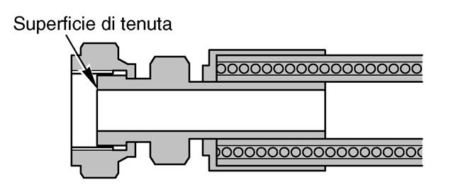
Thread diameter of nut part (mm) Width across flats of nut part (mm) TIGHTENING TORQUE kgmNm 1/2” - 20 9/16” - 18 3/4” - 16 7/8” - 14 1.1/16 - 12 1.5/16 - 12 1.5/8 - 12 22 33 17 17 22 27 32 38 50 27 41 2.6±0.5 4±0.5 6.7±2 8±2 9.7±3 17±3 20±5 8±2 20±5 25.5±4.9 39.2±4.9 65.7±19.6 78.5±19.6 95.15±29.4 166.7±29.4 196.2±49 78.5±19.6 196.2±49 Thread diameter of nut part (mm) Width across flats of nut part (mm) TIGHTENING TORQUE kgmNm 9/16” - 18 11/16” - 16 13/16” - 16 1” - 14 1.3/16 - 12 1.7/16 - 12 1.11/16 - 12 2” - 12 17 22 24 30 36 41 50 57 2.3–2.5 3.4–3.9 5.2–5.8 8.2–9.2 12.2–13.3 15.3–17.3 18.4–20.4 20.4–24.4 23–25 33–38 51–57 80–90 120–130 150–170 180–200 200–240 Sealing surface
COATING MATERIALS
The recommended coating materials prescribed in Komatsu Utility Shop Manuals are listed below:
NomenclatureCodeApplications
ASL800010Used to apply rubber pads, rubber gaskets and cork plugs.
ASL800020 Used to apply resin, rubber, metallic and non-metallic parts when a fast, strong seal is needed.
Loctite 222Used for low resistance locking of screws, check nuts and adjustment nuts.
Loctite 242
To prevent the loosening of bolts, nuts and plugs and the leakage of oil. Used for medium resistance locking of screws and nuts of every type, and for locking keys and bearings.
Loctite 262Used for high resistant of threaded parts that can be removed with normal tools.
Adhesives
Loctite 270 Used for high resistant locking and for sealing threaded parts, bolts and stud bolts.
Loctite 542Used for sealing the union threads for hydraulic tubes.
Loctite 573 Used for sealing rather exact plane surfaces when the option of possible future dismantling is required.
Loctite 601 Used for high resistant locking of mechanical components that can be removed only after heating
Loctite 675 Used to lock cylindrical couplings and for the permanent locking of threaded parts, and also to lock shafts to bearings, gears, pulleys, pins, bushings, etc.
ASL800060 Used by itself to seal grease fittings, tapered screw fittings and tapered screw fittings in hydraulic circuits of less than 50 mm in diameter.
Gasket sealant
Loctite 510 Used by itself on mounting flat surface (Clearance between surfaces within 0.2 mm)
Loctite 518 Used by itself on mounting flat surface (Clearance between surfaces within 0.5 mm
Antifriction compound (Lubricant including Molybdenum disulfide)
Grease (Lithium grease)
ASL800040 Applied to bearings and taper shaft to facilitate press-fitting and to prevent sticking, burning or rusting.
ASL800050 Applied to bearings, sliding parts and oil seals for lubrication, rust prevention and facilitation of assembling work.
Vaseline Used for protecting battery electrode terminals from corrosion
WH6 - WH7 00-12 COATING MATERIALS 2
In the wiring diagrams various colour and symbols are employed to indicate the thickness of wires. This wire code table will help you understand WIRING DIAGRAMS.
Example: R–N 1.5 indicates a cable having a nominal number 1.5 and red coating with black stripe. CLASSIFICATION BY THICKNESS
CLASSIFICATION BY COLOUR AND CODE
PrimaryAuxiliary
CodeAA–BA/BA–G–A–NA/NA–RA/RA–VA/V ColourLight BlueLight Blue – WhiteLight Blue–YellowLight Blue–BlackLight Blue–RedLight Blue–Green
CodeBB–G–B–NB/NB–RB/R–B/V––ColourWhiteWhite–YellowWhite–BlackWhite–RedWhite–Green–CodeCC–BC/BC–L–C–N–––––ColourOrangeOrange–WhiteOrange–BlueOrange–Black––CodeGG–NG/NG–R–G–V–––––ColourYellowYellow–BlackYellow–RedYellow–Green––CodeHH–L–H–NH/N––––––ColourGreyGrey–BlueGrey–Black–––CodeLL–BL/BL–G––L/N––––ColourBlueBlue–WhiteBlue–YellowBlue–Black––CodeMM–B–M–NM/NM–V–––––ColourBrownBrown–WhiteBrown–BlackBrown–Green––CodeN––––––––––ColourBlack–––––CodeRR–G–R–NR/NR–V–––––ColourRedRed–YellowRed–BlackRed–Green––CodeSS–G–S–N–––––––ColourPinkPink–YellowPink–Black–––CodeVV–B–V–NV/N––––––ColourGreenGreen–WhiteGreen–Black–––CodeZZ–BZ/BZ–NZ/N––––––ColourVioletViolet–WhiteViolet–Black–––
COMPOSITION OF THE COLOURS
The coloration of two-colour wires is indicated by the composition of the symbol listed.
Example:G–V = Yellow-Green with longitudinal colouring
G/V = Yellow-Green with transversal colouring
ELECTRIC
WH6 - WH7 00-13
ELECTRIC ELECTRIC
Nominal number Copper wire Cable O.D. (mm) Current rating (A) Number strands Ø of strands (mm) Cross section (mm) 0.5160.200.351.553.5 1140.300.992.8011 1.5210.301.483.3514 2.5350.302.473.8020 4560.303.954.6028 6840.305.935.2037 10840.4010.557.1053 503990.4050.1114160
WEIGHT TABLE
k This weight table is a guide for use when transporting or handling components.
WH6 - WH7
WEIGHT
00-14
TABLE
Unit: kg Machine modelWH609WH613WH713WH714WH716 Engine assembly390.0390.0390.0390.0390.0 Radiator - exchanger36.036.036.036.036.0 Hydraulic oil tank (empty)70.070.086.670.070.0 Fuel tank (empty)10.010.010.010.010.0 Engine hood45.045.045.045.045.0 Cabin (with seat)476.0476.0476.0476.0476.0 Seat34.034.034.034.034.0 Engine-gear box-pump group672672672672672 Piston pump21.621.621.621.621.6 Transmission 260.0260.0260.0260.0260.0 Front axle 436.5436.5436.5436.5436.5 Rear axle 435.0435.0435.0435.0435.0 Front wheel Rear wheel 140.0140.0140.0140.0140.0 Control valve30.030.030.030.030.0 Telescopic arm assembly (2-section boom) •Basic boom •Top boom 1382.0 523.0 510.0 ––––––––––––Telescopic arm assembly (3-section boom) •Basic boom •Intermediate boom •Top boom ––––2112.0 627.0 400.0 510.0 2288.0 690.0 430.0 540.0 2318.0 690.0 430.0 540.0 2588.0 762.0 494.0 567.0 Outrigger638.0638.0638.0638.0638.0 Boom lift cylinder280.0280.0292.0292.0292.0 Boom extension cylinder141.0217.0217.0247.0370.0 Frame levelling cylinder–28.728.728.728.7 Outrigger cylinder65.265.265.265.265.2 Locking axle cylinder–35.035.035.035.0 Offset cylinder32.032.032.032.032.0 Bucket cylinder90.090.090.090.090.0
TABLE OF OIL AND COOLANT QUANTITIES
WH6 - WH7 00-15 TABLE
OF OIL AND COOLANT QUANTITIES
✽ ASTM D975 N. 1 TANK/ RESERVOIR FLUID AMBIENT TEMPERATURECAPACITY (l) 1st filling Change Engine oil pan In cold climates OIL ACEA E5 - E4 12.812.8 OIL API CH-4 / CI-4 ACEA E5 - E3 Chains lubrication ENGINE OIL as requiredas required Hydraulic system OIL CF - CF2 - CD 11795 Hydraulic system with biodegradable oil see «4.3.1»11795 Front axle: Differential OIL UTTO FLUID 7.17.1 Final reduction gear (ea.) 0.70.7 Rear axle: Differential 7.17.1 Final reduction gear (ea.) 0.70.7 Hydraulic transmission OIL ATF GM DEXRON® II D (DEXRON® is a registered trademark of General Motors Corporation) 12.210.4 Transmission reduction gear 0.250.25 Braking system 0.650.65 Fuel tankDIESEL OIL 130130 Engine cooling system PERMANENT COOLANT 20–-30-20-1001020304050 °C SAE 5W-30 SAE 15W-40 SAE 15W-40 SAE 10W-30 * ASTM D975 N. 2
TABLE OF OIL AND COOLANT QUANTITIES
ASTM: America Society of Testing and Materials
SAE: Society of Automotive Engineers
API: American Petroleum Institute
MIL: Military Specification
CCMC: Common Market Constructors Committe
First filling quantity: total quantity of oil, including the oil for the components and pipes. Oil change quantity: quantity of oil necessary to fill the system or unit during the normal inspection and maintenance operations.
NOTE:
(1)When the diesel oil sulphur content is less then 0.5%, change the engine oil according to the periodic maintenance intervals indicated in the operation and maintenance manual. In the diesel oil sulphur content exceeds 0.5% change the engine oil according to the following table:
(2)When starting the engine at temperatures below 0 °C, use engine oil SAE 10W, 20W-20, even if during the day the temperature increases by 10 °C.
(3)Use engine oil with CD classification; if oil with CC classification is used, reduce the engine oil change interval by a half.
(4)Use original products, which have characteristics specifically formulated and approved for the engine, the hydraulic circuit of equipment and for reductions.
WH6 - WH7 00-16
Sulphur contentEngine oil change interval from 0.5 to 1.0%1/2 o f regular interval over 1.0%1/4 o f regular interval
CONVERSION TABLE
METHOD OF USING THE CONVERSION TABLE
The conversion table in this section is provided to enable simple conversion of figures. For details of the method of using the conversion table, see the example given below.
EXAMPLE
•Method of using the conversion table to convert from millimeters to inches.
1.Convert 55 mm into inches.
1 -Locate the number 50 in the vertical column at the left side, take this as , then drow a horizontal line from
2 -Locate the number 5 in the row across the top, take this as , then draw a perpendicular line down from .
3 -Take the point where the two lines cross as . This point gives the value when converting from millimeters to inches. Therefore, 55 mm =2.165 in.
2.Convert 550 mm into inches
1 -The number 550 does not appear in the table, so divide by 10 (move the decimal point one place to the left) to convert it to 55 mm.
2 -Carry out the same procedure as above to convert 55 mm to 2.165 in.
3 -The original value (550 mm) was divided by 10, so multiply 2.165 in. by 10 (move the decimal point one place to the right) to return to the original value. This gives 550 mm = 21.65 in.
WH6 - WH7 00-17 CONVERSION TABLE
From millimeters to inches 1 mm = 0.03937 in. 0 1 2 3 4 5 6 7 8 9 0 10 20 30 40 50 60 70 80 90 0 0.394 0.787 1.181 1.575 1.969 2.362 2.756 3.150 3.543 0.039 0.433 0.827 1.220 1.614 2.008 2.402 2.795 3.189 3.583 0.079 0.472 0.866 1.260 1.654 2.047 2.441 2.835 3.228 3.622 0.118 0.512 0.906 1.299 1.693 2.087 2.480 2.874 3.268 3.661 0.157 0.551 0.945 1.339 1.732 2.126 2.520 2.913 3.307 3.701 0.197 0.591 0.984 1.378 1.772 2.165 2.559 2.953 3.346 3.740 0.236 0.630 1.024 1.417 1.811 2.205 2.598 2.992 3.386 3.780 0.276 0.669 1.063 1.457 1.850 2.244 2.638 3.032 3.425 3.819 0.315 0.709 1.102 1.496 1.890 2.283 2.677 3.071 3.465 3.858 0.354 0.748 1.142 1.536 1.929 2.323 2.717 3.110 3.504 3.898 A A B C C A B C
WH6 - WH7 00-18 From mm to in. 1 mm = 0.03937 in. From kg to lb. 1 kg = 2.2046 lb. 0123456789 0 10 20 30 40 50 60 70 80 90 0 0.394 0.787 1.181 1.575 1.969 2.362 2.756 3.150 3.543 0.039 0.433 0.827 1.220 1.614 2.008 2.402 2.795 3.189 3.583 0.079 0.472 0.866 1.260 1.654 2.047 2.441 2.835 3.228 3.622 0.118 0.512 0.906 1.299 1.693 2.087 2.480 2.874 3.268 3.661 0.157 0.551 0.945 1.339 1.732 2.126 2.520 2.913 3.307 3.701 0.197 0.591 0.984 1.378 1.772 2.165 2.559 2.953 3.346 3.740 0.236 0.630 1.024 1.417 1.811 2.205 2.598 2.992 3.386 3.780 0.276 0.669 1.063 1.457 1.850 2.244 2.638 3.032 3.425 3.819 0.315 0.709 1.102 1.496 1.890 2.283 2.677 3.071 3.465 3.858 0.354 0.748 1.142 1.536 1.929 2.323 2.717 3.110 3.504 3.898 0123456789 0 10 20 30 40 50 60 70 80 90 0 22.05 44.09 66.14 88.18 110.23 132.28 154.32 176.37 198.42 2.20 24.25 46.30 68.34 90.39 112.44 134.48 156.53 178.57 200.62 4.41 26.46 48.50 70.55 92.59 114.64 136.69 158.73 180.78 202.83 6.61 28.66 50.71 72.75 94.80 116.85 138.89 160.94 182.98 205.03 8.82 30.86 51.91 74.96 97.00 119.05 141.10 163.14 185.19 207.24 11.02 33.07 55.12 77.16 99.21 121.24 143.30 165.35 187.39 209.44 13.23 35.27 57.32 79.37 101.41 123.46 145.51 167.55 189.60 211.64 15.43 37.48 59.53 81.57 103.62 125.66 147.71 169.76 191.80 213.85 17.64 39.68 61.73 83.78 105.82 127.87 149.91 171.96 194.01 216.05 19.84 41.89 63.93 85.98 108.03 130.07 152.12 174.17 196.21 218.26
WH6 - WH7 00-19 From liter to U.S. Gall. 1 = 0.2642 U.S. Gall. From liter to U.K. Gall. 1 = 0.21997 U.K. Gall. 0123456789 0 10 20 30 40 50 60 70 80 90 0 2.642 5.283 7.925 10.567 13.209 15.850 18.492 21.134 23.775 0.264 2.906 5.548 8.189 10.831 13.473 16.115 18.756 21.398 24.040 0.528 3.170 5.812 8.454 11.095 13.737 16.379 19.020 21.662 24.304 0.793 3.434 6.076 8.718 11.359 14.001 16.643 19.285 21.926 24.568 1.057 3.698 6.340 8.982 11.624 14.265 16.907 19.549 22.190 24.832 1.321 3.963 6.604 9.246 11.888 14.529 17.171 19.813 22.455 25.096 1.585 4.227 6.869 9.510 12.152 14.795 17.435 20.077 22.719 25.361 1.849 4.491 7.133 9.774 12.416 15.058 17.700 20.341 22.983 25.625 2.113 4.755 7.397 10.039 12.680 15.322 17.964 20.605 23.247 25.889 2.378 5.019 7.661 10.303 12.944 15.586 18.228 20.870 23.511 26.153 0123456789 0 10 20 30 40 50 60 70 80 90 0 2.200 4.399 6.599 8.799 10.998 13.198 15.398 17.598 19.797 0.220 2.420 4.619 6.819 9.019 11.281 13.418 15.618 17.818 20.017 0.440 2.640 4.839 7.039 9.239 11.438 13.638 15.838 18.037 20.237 0.660 2.860 5.059 7.259 9.459 11.658 13.858 16.058 12.257 20.457 0.880 3.080 5.279 7.479 9.679 11.878 14.078 16.278 18.477 20.677 1.100 3.300 5.499 7.969 9.899 12.098 14.298 16.498 18.697 20.897 1.320 3.520 5.719 7.919 10.119 12.318 14.518 16.718 18.917 21.117 1.540 3.740 5.939 8.139 10.339 12.528 14.738 16.938 19.137 21.337 1.760 3.950 6.159 8.359 10.559 12.758 14.958 17.158 19.357 21.557 1.980 4.179 6.379 8.579 10.778 12.978 15.178 17.378 19.577 21.777
WH6 - WH7 00-20 From Nm to lb.ft. 1 Nm = 0.737 lb.ft. 0123456789 0 10 20 30 40 50 60 70 80 90 100 110 120 130 140 150 160 170 180 190 0 7.370 14.740 22.110 29.480 36.850 44.220 51.590 58.960 66.330 73.700 81.070 88.440 95.810 103.180 110.550 117.920 125.290 132.660 140.030 0.737 8.107 15.477 22.847 30.217 37.587 44.957 52.327 59.697 67.067 74.437 81.807 89.177 96.547 103.917 111.287 118.657 126.027 133.397 140.767 1.474 8.844 16.214 23.584 30.954 38.324 45.694 53.064 60.434 67.804 75.174 82.544 89.914 97.284 104.654 112.024 119.394 126.764 134.134 141.504 2.211 9.581 16.951 24.321 31.691 39.061 46.431 53.801 61.171 68.541 75.911 83.281 90.651 98.021 105.391 112.761 120.131 127.501 134.871 142.241 2.948 10.318 17.688 25.058 32.428 39.798 47.168 54.538 61.908 69.278 76.648 84.018 91.388 98.758 106.128 113.498 120.868 128.238 135.608 142.978 3.685 11.055 18.425 25.795 33.165 40.535 47.905 55.275 82.645 70.015 77.385 84.755 92.125 99.495 106.865 114.235 121.605 128.975 136.345 143.715 4.422 11.792 19.162 26.532 33.902 41.272 48.642 56.012 63.382 70.752 78.122 85.492 92.862 100.232 107.602 114.972 122.342 129.712 137.082 144.452 5.159 12.529 19.899 27.269 34.639 42.009 49.379 56.749 64.119 71.489 78.859 86.229 93.599 100.969 108.339 115.709 123.079 130.449 137.819 145.189 5.896 13.266 20.636 28.006 35.376 42.746 50.116 57.486 64.856 72.226 79.596 86.966 94.336 101.706 109.076 116.446 123.816 131.186 138.556 145.926 6.633 14.003 21.373 28.743 36.113 43.483 50.853 58.223 65.593 72.963 80.333 87.703 95.073 102.443 109.813 117.183 124.553 131.923 139.293 146.663
WH6 - WH7
From Nm to kgm 1 Nm = 0.102 kgm 0123456789 0 10 20 30 40 50 60 70 80 90 100 110 120 130 140 150 160 170 180 190 0 1.020 2.040 3.060 4.080 5.100 6.120 7.140 8.160 9.180 10.200 11.220 12.240 13.260 14.280 15.300 16.320 17.340 18.360 19.380 0.102 1.222 2.142 3.162 4.182 5.202 6.222 7.242 8.262 9.282 10.302 11.322 12.342 13.362 14.382 15.402 16.422 17.442 18.462 19.482 0.204 1.224 2.244 3.264 4.284 5.304 6.324 7.344 8.364 9.384 10.404 11.424 12.444 13.464 14.484 15.504 16.524 17.544 18.564 19.584 0.306 1.326 2.346 3.366 4.386 5.406 6.426 7.446 8.466 9.486 10.506 11.526 12.546 13.566 14.586 15.606 16.626 17.646 18.666 19.686 0.408 1.428 2.448 3.468 4.488 5.508 6.528 7.548 8.568 9.588 10.608 11.628 12.648 13.668 14.688 15.708 16.728 17.748 18.768 19.788 0.510 1.530 2.550 3.570 4.590 5.610 6.630 7.650 8.670 9.690 10.710 11.730 12.750 13.770 14.790 15.810 16.830 17.850 18.870 19.890 0.612 1.632 2.652 3.672 4.692 5.712 6.732 7.752 8.772 9.792 10.812 11.832 12.852 13.872 14.892 15.912 16.932 17.952 18.972 19.992 0.714 1.734 2.754 3.774 4.794 5.814 6.834 7.854 8.874 9.894 10.914 11.934 12.954 13.974 14.994 16.014 17.034 18.054 19.074 20.094 0.816 1.836 2.856 3.876 4.896 5.916 6.936 7.956 8.976 9.996 11.016 12.036 13.056 14.076 15.096 16.116 17.136 18.156 19.176 20.196 0.918 1.938 2.958 3.978 4.998 6.018 7.038 8.058 9.078 10.098 11.118 12.138 13.158 14.178 15.198 16.218 17.238 18.258 19.278 20.298
00-21
WH6 - WH7 00-22 From kgm to lb.ft. 1 kgm = 7.233 lb.ft. 0123456789 0 10 20 30 40 50 60 70 80 90 100 110 120 130 140 150 160 170 180 190 0 72.3 144.7 217.0 289.3 361.7 434.0 506.3 578.6 651.0 723.3 795.6 868.0 940.3 1012.6 1084.9 1157.3 1129.6 1301.9 1374.3 7.2 79.6 151.9 224.2 296.6 368.9 441.2 513.5 585.9 658.2 730.5 802.9 875.2 947.5 1019.9 1092.2 1164.5 1236.8 1309.2 1381.5 14.5 86.8 159.1 231.5 303.8 376.1 448.5 520.8 593.1 665.4 737.8 810.1 882.4 954.8 1027.1 1099.4 1171.7 1244.1 1316.4 1388.7 21.7 94.0 166.4 238.7 311.0 383.4 455.7 528.0 600.3 672.2 745.0 817.3 889.7 962.0 1034.3 1106.6 1179.0 1251.3 1323.6 1396.0 28.9 101.3 173.6 245.9 318.3 390.6 462.9 535.2 607.6 679.9 752.2 824.6 896.9 969.2 1041.5 1113.9 1186.2 1258.5 1330.9 1403.2 36.2 108.5 180.8 253.2 325.5 397.8 470.2 542.5 614.8 687.1 759.5 831.8 904.1 876.5 1048.8 1121.1 1193.4 1265.8 1338.1 1410.4 43.4 115.7 188.1 260.4 332.7 405.1 477.4 549.7 622.0 694.4 766.7 839.0 911.4 983.7 1056.0 1128.3 1200.7 1273.0 1345.3 1417.7 50.6 123.0 195.3 267.6 340.0 412.3 484.6 556.9 629.3 701.6 773.9 846.3 918.6 990.9 1063.2 1135.6 1207.9 1280.1 1352.6 1424.9 57.9 130.2 202.5 274.9 347.2 419.5 491.8 564.2 636.5 708.8 781.2 853.5 925.8 998.2 1070.5 1142.8 1215.1 1287.5 1359.8 1432.1 65.1 137.4 209.8 282.1 354.4 426.8 499.1 571.4 643.7 716.1 788.4 860.7 933.1 1005.4 1077.7 1150.0 1222.4 1294.7 1367.0 1439.4
WH6 - WH7 00-23 From bar to psi (lb/in2) 1 bar = 14.503 psi 0123456789 0 10 20 30 40 50 60 70 80 90 100 110 120 130 140 150 160 170 180 190 200 210 220 230 240 0 145.0 290.0 435.1 580.1 725.1 870.2 1015.2 1160.2 1305.3 1450.3 1595.3 1740.4 1885.4 2030.4 2175.4 2320.5 2465.5 2610.5 2755.6 2900.6 3045.6 3190.7 3335.7 3480.7 14.5 159.5 304.6 449.6 594.6 739.6 884.7 1029.7 1174.7 1319.8 1464.8 1609.8 1754.9 1899.9 2044.9 2189.9 2335.0 2480.0 2625.0 2770.0 2915.1 3060.1 3205.2 3350.2 3495.2 29.0 174.0 319.1 464.1 609.1 754.1 899.2 1044.2 1189.2 1334.3 1479.3 1624.3 1769.4 1914.4 2059.4 2204.4 2349.5 2494.5 2639.5 2784.6 2929.6 3074.6 3219.7 3364.7 3509.7 43.5 188.5 333.6 478.6 623.6 768.6 913.7 1058.7 1203.7 1348.8 1493.8 1638.8 1783.9 1928.9 2073.9 2218.9 2364.0 2509.0 2654.0 2799.1 2944.1 3089.1 3234.2 3379.2 3524.2 58.0 203.0 348.1 493.1 638.1 783.2 928.2 1073.2 1218.2 1363.3 1508.3 1653.3 1798.4 1943.4 2088.4 2233.5 2378.5 2523.5 2668.5 2813.6 2958.6 3103.6 3248.7 3393.7 3538.7 72.5 217.5 362.6 507.6 652.6 797.7 942.7 1087.7 1232.7 1377.8 1522.8 1667.8 1812.9 1957.9 2102.9 2248.0 2393.0 2538.0 2683.0 2828.1 2973.1 3118.1 3263.2 3408.2 3553.2 87.0 232.0 377.1 522.1 667.1 812.2 957.2 1102.2 1247.2 1392.3 1537.3 1682.3 1827.4 1972.4 1217.4 2262.5 2407.5 2552.5 2697.7 2842.6 2987.6 3132.6 3277.7 3422.7 3567.7 101.5 246.5 391.6 536.6 681.6 826.7 971.7 1116.7 1261.8 1406.8 1551.8 1696.8 1841.9 1986.9 2131.9 2277.0 2422.0 2567.0 2712.1 2857.1 3002.1 3147.1 3192.2 3437.2 3582.2 116.0 261.0 406.1 551.1 696.1 841.2 986.2 1131.2 1276.3 1421.3 1566.3 1711.3 1856.4 2001.4 2146.4 2291.5 2436.5 2581.5 2726.6 2871.6 3016.6 3161.6 3306.7 3451.7 3596.7 130.5 275.6 420.6 565.6 710.6 855.7 1000.7 1145.7 1290.8 1435.8 1580.8 1725.8 1870.8 2015.9 2160.9 2306.0 2451.0 2596.0 2641.1 2886.1 3031.1 3176.1 3321.2 3466.2 3611.2
TEMPERATURE
Fahrenheit-Centigrade conversion; a simple way to convert a Fahrenheit temperature reading into a Centigrade temperature reading or vice versa is to enter the accompanying table in the center or boldface column of figures. These figures refer to the temperature in either Fahrenheit or Centigrade degrees.
If it is desired to convert from Fahrenheit to Centigrade degrees, consider the center column as a table of Fahrenheit temperatures and read the corresponding Centigrade temperature in the column at the left.
If it is desired to convert from Centigrade to Fahrenheit degrees, consider the center column as a table of Centigrade values and read the corresponding Fahrenheit temperature on the right.
1 °C = 33.8°F
WH6 - WH7 00-24
°C °F°C °F°C °F°C °F –40.4 –37.2 –34.4 –31.7 –28.9 –28.3 –27.8 –27.2 –26.7 –26.1 –25.6 –25.0 –24.4 –23.9 –23.3 –22.8 –22.2 –21.7 –21.1 –20.6 –20.0 –19.4 –18.9 –18.3 –17.8 –17.2 –16.7 –16.1 –15.6 –15.0 –14.4 –13.9 –13.3 –12.8 –12.2 –40 –35 –30 –25 –20 –19 –18 –17 –16 –15 –14 –13 –12 –11 –10 –9 –8 –7 –6 –5 –4 –3 –2 –1 0 1 2 3 4 5 6 7 8 9 10 –40.0 –31.0 –22.0 –13.0 –4.0 –2.2 –0.4 1.4 3.2 5.0 6.8 8.6 10.4 12.2 14.0 15.8 17.6 19.4 21.2 23.0 24.8 26.6 28.4 30.2 32.0 33.8 35.6 37.4 39.2 41.0 42.8 44.6 46.4 48.2 50.0 –11.7 –11.1 –10.6 –10.0 –9.4 –8.9 –8.3 –7.8 –7.2 –6.7 –6.1 –5.6 –5.0 –4.4 –3.9 –3.3 –2.8 –2.2 –1.7 –1.1 –0.6 0.0 0.6 1.1 1.7 2.2 2.8 3.3 3.9 4.4 5.0 5.6 6.1 6.7 7.2 11 12 13 14 15 16 17 18 19 20 21 22 23 24 25 26 27 28 29 30 31 32 33 34 35 36 37 38 39 40 41 42 43 44 45 51.8 53.6 55.4 57.2 59.0 60.8 62.6 64.4 66.2 68.0 69.8 71.6 73.4 75.2 77.0 78.8 80.6 72.4 84.2 86.0 87.8 89.6 91.4 93.2 95.0 96.8 98.6 100.4 102.2 104.0 105.8 107.6 109.4 111.2 113.0 7.8 8.3 8.9 9.4 10.0 10.6 11.1 11.7 12.2 12.8 13.3 13.9 14.4 15.0 15.6 16.1 16.7 17.2 17.8 18.3 18.9 19.4 20.0 20.6 21.1 21.7 22.2 22.8 23.3 23.9 24.4 25.0 25.6 26.1 26.7 46 47 48 49 50 51 52 53 54 55 56 57 58 59 60 61 62 63 64 65 66 67 68 69 70 71 72 73 74 75 76 77 78 79 80 144.8 116.6 118.4 120.2 122.0 123.8 125.6 127.4 129.2 131.0 132.8 134.6 136.4 138.2 140.0 141.8 143.6 145.4 147.2 149.0 150.8 152.6 154.4 156.2 158.0 159.8 161.6 163.4 165.2 167.0 168.8 170.6 172.4 174.2 176.0 27.2 27.8 28.3 28.9 29.4 30.0 30.6 31.1 31.7 32.2 32.8 33.3 33.9 34.4 35.0 35.6 36.1 36.7 37.2 37.8 40.6 43.3 46.1 48.9 51.7 54.4 57.2 60.0 62.7 65.6 68.3 71.1 73.9 76.7 79.4 81 82 83 84 85 86 87 88 89 90 91 92 93 94 95 96 97 98 99 100 105 110 115 120 125 130 135 140 145 150 155 160 165 170 175 117.8 179.6 181.4 183.2 185.0 186.8 188.6 190.4 192.2 194.0 195.8 197.6 199.4 201.2 203.0 204.8 206.6 208.4 210.2 212.0 221.0 230.0 239.0 248.0 257.0 266.0 275.0 284.0 2930 302.0 311.0 320.0 329.0 338.0 347.0
10 STRUCTURE AND FUNCTION
10-1 WH6 - WH7
ENGINE-TRANSMISSION COUPLING....................2 POWER TRAIN.........................................................3 TRANSMISSION.......................................................5 FRONT AXLE..........................................................31 REAR AXLE............................................................35 BRAKE PUMPS.......................................................39 STEERING SYSTEM (4WS)...................................40 STEERING UNIT.....................................................44 HYDRAULIC DIAGRAM..........................................45 HYDRAULIC PUMP.................................................46 CONTROL VALVE...................................................50 PPC VALVE.............................................................51 SOLENOID VALVES................................................54 SAFETY VALVES....................................................59 CYLINDERS.............................................................66 AIR CONDITIONING SYSTEM................................73 CLIMATE CONTROL SYSTEM OPERATION.........74 ELECTRICAL DIAGRAMS.......................................75
10-2 WH6 - WH7 STRUCTURE
ENGINE-TRANSMISSION COUPLING
AND FUNCTION
ENGINE-TRANSMISSION COUPLING
1.Engine
2.Flange
3.Screw
1 2 3
4.Transmission
4 RKT00010
DESCRIPTION
•The driving power generated by the engine (1) is transmitted through the flywheel to the converter (2). The converter uses hydraulic oil to convert the torque transmitted by the engine (1) into driving power. The converter (2) transmits motion to the drive shaft of the transmission (3) and to the drive shaft of the hydraulic pump (4).
•The transmission (3) has two hydraulically-activated clutches that can be selected by an electrically-controlled gear selector.
•The driving power is transmitted from the transmission flanges (3) to the front (5) and rear (6) axles through the cardan drive shafts (7 and 8).
•The driving power transmitted to the front (5) and rear (6) axles is reduced by the differentials and then transmitted to the final drives (9) through the drive shafts.
10-3 WH6 - WH7 STRUCTURE AND FUNCTION POWER TRAIN POWER
1 RKT00020 2 3 4 5 7 8 6 9 9 9 9
TRAIN
10-4 WH6 - WH7 STRUCTURE AND FUNCTION POWER TRAIN RKT00030 5 10 9 7 8 6 1 2 4 3
Front of machine
1.Diesel engine
2.Converter
3. Transmission
4. Hydraulic pump
5.Front axle
6. Rear axle
7. Front cardan shaft
8. Rear cardan shaft
9.Rear wheels
10. Front wheels
DIAGRAM OF THE POWER TRAIN
10-5
WH6
-
WH7
STRUCTURE AND FUNCTION TRANSMISSION TRANSMISSION
1.Engine
2. Converter
3. Transmission
4. Hydraulic pump
5. Rear flange
RKT00040 2 1 4 3 6 5
6. Front flange
10-6 WH6 - WH7 STRUCTURE AND FUNCTION TRANSMISSION RKT00060 1 d 6 4 3 a 7 5 2 8 c b 3
a.Port 12 - from the oil cooler
b.Port 11 - to the oil cooler
c.Port 31 - from the brake pump (P Port)
d.Port 71 - from the brake pump (S Port)
1.Converter
2.Filter
3.Transmission oil drain plug
4.Drop box oil drain plug
5.Transmission plug vent
6.Drop box plug vent
7.Rotational speed sensor (YV)
8.Oil temperature sensor (X56)
ELECTRICAL COMPONENTS
1.YR - Reverse clutch solenoid valve
2.YF - Forward clutch solenoid valve
3.YS - Gear selector solenoid valve
4.Y1 - 1st clutch solenoid valve
5.Y2 - 2nd clutch solenoid valve
CHECK POINTS
a.31 Port -Clutch pressure
b.33 Port - Delivery pressure to intercooler
c.32 Port -Pressione mandata all’intercooler
d.41 Port -1st clutch pressure
e.42 Port -2nd clutch pressure
f.43 Port -3rd clutch pressure
g.44 Port -4th clutch pressure
h.45 Port - Forward gear pressure
i.46 Port -Reverse gear pressure
WH6 - WH7
10-7
STRUCTURE
TRANSMISSION
RKT00061 b a c h i d e f g 1 2 3 4 5
AND FUNCTION
TRANSMISSION
STRUCTURE AND FUNCTION TRANSMISSION
10-8
- WH7
WH6
1.Direction selection clutch shaft
2.3rd and 4th clutch shaft
3.1st and 2nd clutch shaft
4.Transmission output shaft
5.Drop box output shaft
6.Front cardan flange
1 2 4 5 6 7 3 YR YF YS Y1 Y2
7.Rear flange
RKT00070
Forward gear clutch
3th clutch
Reverse gear clutch
2nd clutch
1st clutch
4th clutch