
Foreword
This diagnostic manual applies to the following tractor types:
7130 Premium, 7230 Premium, 7330 Premium, 7430 Premium and 7530 Premium.
This manual is written for experienced technicians. Essential tools required in performing certain service work are identified in this manual and are recommended for use.
Live with safety: Read the safety messages in the initial section of this manual and the cautions presented throughout the text of the manual.
Serial Number Break 2008
Up to tractor serial number 006999
From tractor serial number 007000
Among other things, the following changes have been incorporated in the current series from tractor serial number 007000:
• Wiring harnesses (functional schematics)


• Diagnostic addresses
• Fuse arrangement
• Software
NOTE: As the changes were made during the ongoing production, the serial number break does not represent a clean cut, i.e. changes have already been incorporated in some tractors up to serial number 006999 and have not yet been incorporated in some tractors from serial number 007000. The relevant tractors can be identified on the basis of the fuse arrangement.
This is the safety-alert symbol. When you see this symbol on your machine or in this manual, be alert to the potential for personal injury.
Technical Manuals are service guidelines for specific machines. They are on-the-job guides containing only the vital information needed for diagnosis, analysis, testing and repair.
Fundamental service information is available from other sources covering basic theory of operation, fundamentals of troubleshooting, general maintenance and basic type of failures and their causes.
Section 210 General Information
Group 05 Safety Information
Group 10 General References
Section 211—Diagnostic Trouble Codes
Group ATC ATC Control Unit
Group BCU BCU Control Unit
Group BIF BIF Control Unit
Group DSM DSM Control Unit
Group DTI DTI Control Unit
Group ECU ECU Control Unit
Group EPC EPC Control Unit
Group ETC ETC Control Unit
Group JDL JDL Control Unit
Group PLC PLC Control Unit
Group SIC SIC Control Unit
Group SSU SSU Control Unit
Group TCU TCU Control Unit
Group TEC TEC Control Unit
Group TEI TEI Control Unit
Group TSC TSC Control Unit
Group UIC UIC Control Unit
Group UIM UIM Control Unit
Group VTI VTI Control Unit
Section 212—Observable Symptoms
Group 40 Electronics
Group 45 Electronic Control Units
Group 53 AutoPowr/IVT Transmission
Group 55 PowrQuad Transmission
Group 56 Drive Systems
Group 60 Steering and Brakes
Group 70 Hydraulic System
Group 80 Miscellaneous
Group 90 Operator’s Cab
Section 213—System Diagnostics
Group 45 Electronics
Group 55 PowrQuad Transmission
Group 70 Hydraulic System
Group JDL JDL - System Diagnostics
Group VTI VTI (GreenStar) - System Diagnostics
Section 220—Engine
Group 05 General Information
Group 10 Operational Checks
Group 15 Tests and Adjustments
Section 230—Fuel, Air Intake and
Cooling Systems
Group 15 Tests and Adjustments
Group 20A Fuel System
Group 20B Air Intake System
Group 20C Cooling System
Group 20D Cold-Weather Starting Aids
Section 240 Electrical System
Group SE01 Starting Motor and Charging Circuit
Group SE01A Fuel Preheater
Group SE01B Electrical Starting Aid
Group SE02 BIF Control Unit (Basic Informator)
Group SE03 Horn
Group SE04 Operator’s Seat and Cigarette Lighter
Group SE06 Lights
Group SE08 Plug for Accessories
Group SE09 Radio Light, Dome Light, Console Light and Access Step Lights
Group SE10 ATC/ETC/HTC Control Units (Air-Conditioning, Fan and Heater)
Group SE14 3- and 7-Terminal Power Outlet Sockets (SAE)
Group SE15 BCU Control Unit (Electronic Hitch Control)
Group SE16 BCU Control Unit (Basic Functions)
Group SE17 Signal Socket and Service Socket
Group SE20 TSC Control Unit (Suspension)
Group SE21 SIC Control Unit (Selective Control Valves)
Group SE22 CAN BUS Terminating Resistor
Group SE23A Level 14 ECU Control Unit (Electronic Engine Control) for 4-Valve Engine with HPCR
Group SE23B Level 16 ECU Control Unit (Electronic Engine Control) for 2-Valve Engine with HPCR
Group SE26 TCU Control Unit (Transmission Control with AutoPowr/IVT Transmission)
Group SE26A EPC Control Unit (Transmission Control with PowrQuad Plus or AutoQuad Plus Transmission)
Group SE27 UIC Control Unit (Transmission Control with AutoPowr/IVT Transmission)
Group SE28 PLC Control Unit (Electronic Park Lock with AutoPowr/IVT Transmission)
Group SE29 Electrical Rear-View Mirrors
Group SE30 JDL Control Unit (JDLink)
Original Instructions. All information, illustrations and specifications in this manual are based on the latest information available at the time of publication. The right is reserved to make changes at any time without notice
Group SE32 TEC Control Unit (ISOBUS)
Group SE33 GreenStar (AMS)
Group SE35 SSU Control Unit (AutoTrac)
Group SE36 UIM/VTI Control Units (GreenStar Display)
Group SE37 Electro-Hydraulic Pick-Up Hitch
Group SE39 PC6 Power Module (HF)
Group SE40 PC0 Power Module
Group SE41 PC5 Power Module
Group SE42 DTI Control Unit (CommandCenter)
Group 105A Component Information - Connectors and Contacts
Group 105B Component Information - Connectors (X001 to X249)
Group 105C Component Information - Connectors (X250 to X499)
Group 105D Component Information - Connectors (X500 to X749)
Group 105E Component Information - Connectors (X750 to X999)
Group 105F Component Information - Connectors (XGND)
Group 110 Component Information - Wiring
Harnesses
Group 115 Component Information - Electrical Parts/Components
Group 115A Component Information - Electrical
Parts/Components (Actuators)
Group 115B Component InformationElectrical Parts/Components (Sensors/Switches/Potentiometers)
Group 115C Component Information - Electrical
Parts/Components (Fuses/Relays/Diodes)
Group 115D Component Information - Electrical
Parts/Components (Headlamps/Lights)
Group 115E Component Information - Electrical
Parts/Components (Other)
Group 120 Component Information - Ground Connections
Group 125 Component Information - CAN BUS Systems
Section 245—Electronic Control Units
Group 05 Operation and General Information on Diagnostics
Group 10A Interactive Tests
Group 10B Interactive Calibrations
Group 15 Information on How to Reprogram Control Units
Group 20 Data BUS Systems
Group ATC ATC Control Unit
Group BCU BCU Control Unit
Group BIF BIF Control Unit
Group DSM DSM Control Unit
Group DTI DTI Control Unit
Group ECU ECU Control Unit
Group EPC EPC Control Unit
Group ETC ETC Control Unit
Group JDL JDL Control Unit
Group PC0 PC0 Power Module
Group PC5 PC5 Power Module
Group PC6 PC6 Power Module (HF)
Group PLC PLC Control Unit
Group SIC SIC Control Unit
Group SSU SSU Control Unit
Group TCU TCU Control Unit
Group TEC TEC Control Unit
Group TSC TSC Control Unit
Group UIC UIC Control Unit
Group UIM UIM Control Unit
Group VTI VTI Control Unit
Section 253 AutoPowr/IVT Transmission
Group 10 Operational Checks
Group 15 Tests and Adjustments
Group 20 Theory of Operation
Section 255 PowrQuad Transmission
Group 10 Operational Checks
Group 15 Tests and Adjustments
Group 20 Theory of Operation
Section 256—Drive Systems
Group 10 Operational Checks
Group 15 Tests and Adjustments
Group 20A Front-Wheel Drive Clutch
Group 20B Differential
Group 20C Final Drives
Group 20D Rear PTO Options
Section 260—Steering and Brakes
Group 05 Introductory Checks
Group 10 Operational Checks
Group 15 Tests and Adjustments
Group 20A Hydrostatic Steering
Group 20B Brake Valve
Group 20C Rear Brakes
Group 20G AutoTrac
Section 270—Hydraulic System
Group 10 Operational Checks
Group 15 Tests and Adjustments
Group 20 Theory of Operation
Group 20A Oil Filter, Charge Pump and Hydraulic Pump
Group 20B Hitch
Group 20C Selective Control Valves (SCVs)
Group 20D Independent Control Valves (ICVs)
Group 20E Hydraulic Block
Section 280 Miscellaneous
Group 10 Operational Checks
Group 15 Tests and Adjustments
Group 20 Theory of Operation
Section 290 Operator’s Cab
Group 10 Operational Checks
Group 15 Tests and Adjustments
Group 20A Ventilation/Heating
Group 20B Air-Conditioning System
Group 20C ClimaTrak
Group 20D Cab Suspension
Section 299—Special Tools
Group 05 Special Tools (Dealer-Fabricated)
Group 10 Special Tools (Available as Spare Parts)
Safety Information
CAUTION: The safety measures are to be followed!
Recognize Safety Information
This is a safety-alert symbol. When you see this symbol on your machine or in this manual, be alert to the potential for personal injury.

Follow recommended precautions and safe operating practices.
LX24603,000052D -19-28FEB07-1/1
”Important” Information
Information marked as IMPORTANT points out problems that may lead to machine damage. By following the directions given, these problems can be avoided.
”Note” Information
When marked with NOTE the information given is more detailed or contains restrictions to directions given
Prevent Machine Runaway
Avoid possible injury or death from machinery runaway. Do not start engine by shorting across starter terminals. Machine will start in gear if normal circuitry is bypassed.
NEVER start engine while standing on ground. Start engine only from operator’s seat, with transmission in neutral or park.
LX,CRA05 002885 -19-09APR92-1/1
previously. On the other hand useful information may be given belonging to certain instructions without being directly connected to them.
LX,CRA05 002886 -19-09APR92-1/1
Handle Fluids Safely—Avoid Fires
When you work around fuel, do not smoke or work near heaters or other fire hazards.

Store flammable fluids away from fire hazards. Do not incinerate or puncture pressurized containers.
Make sure machine is clean of trash, grease, and debris.
Do not store oily rags; they can ignite and burn spontaneously.
Prevent Battery Explosions
Keep sparks, lighted matches, and open flame away from the top of battery. Battery gas can explode.

Never check battery charge by placing a metal object across the posts. Use a volt-meter or hydrometer.
Do not charge a frozen battery; it may explode. Warm battery to 16°C (60°F).
Prepare for Emergencies
Be prepared if a fire starts.
Keep a first aid kit and fire extinguisher handy. Keep emergency numbers for doctors, ambulance service, hospital, and fire department near your telephone.

Prevent Acid Burns
Sulfuric acid in battery electrolyte is poisonous. It is strong enough to burn skin, eat holes in clothing, and cause blindness if splashed into eyes.
Avoid the hazard by:
1. Filling batteries in a well-ventilated area.
2. Wearing eye protection and rubber gloves.
3. Avoiding breathing fumes when electrolyte is added.
4. Avoiding spilling or dripping electrolyte.
5. Use proper jump start procedure.

If you spill acid on yourself:
1. Flush your skin with water.
2. Apply baking soda or lime to help neutralize the acid.
3. Flush your eyes with water for 15 30 minutes. Get medical attention immediately.
If acid is swallowed:
1. Do not induce vomiting.
2. Drink large amounts of water or milk, but do not exceed 2 L (2 quarts).
3. Get medical attention immediately.
Avoid High-Pressure Fluids
Escaping fluid under pressure can penetrate the skin causing serious injury.
Avoid the hazard by relieving pressure before disconnecting hydraulic or other lines. Tighten all connections before applying pressure.
Search for leaks with a piece of cardboard. Protect hands and body from high-pressure fluids.
If an accident occurs, see a doctor immediately. Any fluid injected into the skin must be surgically removed within a few hours or gangrene may result. Doctors unfamiliar with this type of injury should reference a knowledgeable medical source. Such information is available in English from Deere & Company Medical Department in Moline, Illinois, U.S.A., by calling 1-800-822-8262 or +1 309-748-5636.

Service Cooling System Safely
Explosive release of fluids from pressurized cooling system can cause serious burns.
Shut off engine. Only remove filler cap when cool enough to touch with bare hands. Slowly loosen cap to first stop to relieve pressure before removing completely.
Remove Paint Before Welding or Heating
Avoid potentially toxic fumes and dust.
Hazardous fumes can be generated when paint is heated by welding, soldering, or using a torch.
Remove paint before heating:
• Remove paint a minimum of 100 mm (4 in.) from area to be affected by heating. If paint cannot be removed, wear an approved respirator before heating or welding.
• If you sand or grind paint, avoid breathing the dust. Wear an approved respirator.

• If you use solvent or paint stripper, remove stripper with soap and water before welding. Remove solvent or paint stripper containers and other flammable material from area. Allow fumes to disperse at least 15 minutes before welding or heating.
Do not use a chlorinated solvent in areas where welding will take place.
Avoid Heating Near Pressurized Fluid Lines
Flammable spray can be generated by heating near pressurized fluid lines, resulting in severe burns to yourself and bystanders. Do not heat by welding, soldering, or using a torch near pressurized fluid lines or other flammable materials. Pressurized lines can accidentally burst when heat goes beyond the immediate flame area.

Do all work in an area that is well ventilated to carry toxic fumes and dust away.
Dispose of paint and solvent properly.
Work In Ventilated Area
Engine exhaust fumes can cause sickness or death. If it is necessary to run an engine in an enclosed area, remove the exhaust fumes from the area with an exhaust pipe extension.
If you do not have an exhaust pipe extension, open the doors and get outside air into the area.
Wear Protective Clothing
Wear close fitting clothing and safety equipment appropriate to the job.
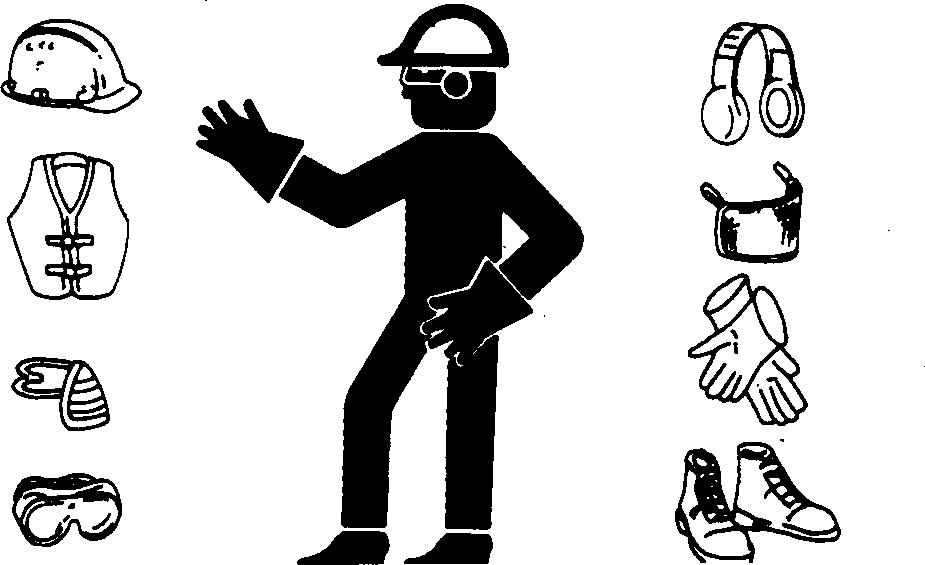
Prolonged exposure to loud noise can cause impairment or loss of hearing.
Wear a suitable hearing protective device such as earmuffs or earplugs to protect against objectionable or uncomfortable loud noises.
Operating equipment safely requires the full attention of the operator. Do not wear radio or music headphones while operating machine.
Practice Safe Maintenance
Understand service procedure before doing work. Keep area clean and dry.
Never lubricate, service, or adjust machine while it is moving. Keep hands, feet , and clothing from power-driven parts. Disengage all power and operate controls to relieve pressure. Lower equipment to the ground. Stop the engine. Remove the key. Allow machine to cool.
Securely support any machine elements that must be raised for service work.
Keep all parts in good condition and properly installed. Fix damage immediately. Replace worn or broken parts. Remove any buildup of grease, oil, or debris.
On self-propelled equipment, disconnect battery ground cable (-) before making adjustments on electrical systems or welding on machine.
On towed implements, disconnect wiring harnesses from tractor before servicing electrical system components or welding on machine.

Park Machine Safely
Before working on the machine:
• Lower all equipment to the ground.

• Stop the engine and remove the key.
• Disconnect the battery ground strap.
• Hang a "DO NOT OPERATE" tag in operator station.
Use Proper Lifting Equipment
Lifting heavy components incorrectly can cause severe injury or machine damage.

Follow recommended procedure for removal and installation of components in the manual.
Construct Dealer-Made Tools Safely
Faulty or broken tools can result in serious injury. When constructing tools, use proper, quality materials, and good workmanship.
Do not weld tools unless you have the proper equipment and experience to perform the job.

Support Machine Properly
Always lower the attachment or implement to the ground before you work on the machine. If the work requires that the machine or attachment be lifted, provide secure support for them. If left in a raised position, hydraulically supported devices can settle or leak down.
Do not support the machine on cinder blocks, hollow tiles, or props that may crumble under continuous load. Do not work under a machine that is supported solely by a jack. Follow recommended procedures in this manual.
When implements or attachments are used with a machine, always follow safety precautions listed in the implement or attachment operator’s manual.
Work in Clean Area
Before starting a job:
• Clean work area and machine.
• Make sure you have all necessary tools to do your job.
• Have the right parts on hand.
• Read all instructions thoroughly; do not attempt shortcuts.
Illuminate Work Area Safely
Illuminate your work area adequately but safely. Use a portable safety light for working inside or under the machine. Make sure the bulb is enclosed by a wire cage. The hot filament of an accidentally broken bulb can ignite spilled fuel or oil.
Service Machines Safely
Tie long hair behind your head. Do not wear a necktie, scarf, loose clothing, or necklace when you work near machine tools or moving parts. If these items were to get caught, severe injury could result.

Remove rings and other jewelry to prevent electrical shorts and entanglement in moving parts.

Use Proper Tools
Use tools appropriate to the work. Makeshift tools and procedures can create safety hazards.
Use power tools only to loosen threaded parts and fasteners.
For loosening and tightening hardware, use the correct size tools. DO NOT use U.S. measurement tools on metric fasteners. Avoid bodily injury caused by slipping wrenches.

Use only service parts meeting John Deere specifications.
Service Tires Safely
Explosive separation of a tire and rim parts can cause serious injury or death.
Do not attempt to mount a tire unless you have the proper equipment and experience to perform the job.

Always maintain the correct tire pressure. Do not inflate the tires above the recommended pressure. Never weld or heat a wheel and tire assembly. The heat can cause an increase in air pressure resulting in a tire explosion. Welding can structurally weaken or deform the wheel.
When inflating tires, use a clip-on chuck and extension hose long enough to allow you to stand to one side and NOT in front of or over the tire assembly. Use a safety cage if available.
Check wheels for low pressure, cuts, bubbles, damaged rims or missing lug bolts and nuts.
Service Front-Wheel Drive Tractor Safely
When servicing front-wheel drive tractor with the rear wheels supported off the ground and rotating wheels by engine power, always support front wheels in a similar manner. Loss of electrical power or transmission/ hydraulic system pressure will engage the front driving wheels, pulling the rear wheels off the support if front wheels are not raised. Under these conditions, front drive wheels can engage even with switch in disengaged position.

Safety Information - Air Brake System
CAUTION: Compressed air tank is pressurized!

Always relieve pressure before working on the air brake system. Do not carry out any welding jobs on the air brake system.
Avoid Eye Contact With Radar
Radar ground speed sensor emits a very low intensity microwave signal. It will not cause any ill effects during normal use. Although intensity is low, DO NOT look directly into face of sensor while in operation, to avoid any possible eye damage.

Keep ROPS Installed Properly
Make certain all parts are reinstalled correctly if the roll-over protective structure (ROPS) is loosened or removed for any reason. Tighten mounting bolts to proper torque.
The protection offered by ROPS will be impaired if ROPS is subjected to structural damage, is involved in an overturn incident, or is in any way altered by welding, bending, drilling, or cutting. A damaged ROPS should be replaced, not reused.
Replace Safety Signs
Replace missing or damaged safety signs. See the machine operator’s manual for correct safety sign placement.

Dispose of Waste Properly
Improperly disposing of waste can threaten the environment and ecology. Potentially harmful waste used with John Deere equipment include such items as oil, fuel, coolant, brake fluid, filters, and batteries.
Use leakproof containers when draining fluids. Do not use food or beverage containers that may mislead someone into drinking from them.
Do not pour waste onto the ground, down a drain, or into any water source.
Air conditioning refrigerants escaping into the air can damage the Earth’s atmosphere. Government regulations may require a certified air conditioning service center to recover and recycle used air conditioning refrigerants.
Inquire on the proper way to recycle or dispose of waste from your local environmental or recycling center, or from your John Deere dealer.

Live With Safety

Before returning machine to customer, make sure machine is functioning properly, especially the safety systems. Install all guards and shields.
Safety Measures on Electronic Control Units
CAUTION: Before installing test equipment
IMPORTANT: Do not use a test lamp on any control on tractor, always shut off the engine and unit. Onlyuseamultimeter(JT05791A/JDG1478). turn off key switch.
IMPORTANT: To protect electronic circuits, disconnect the battery and alternator before CAUTION: Always engage the park lock when performing any welding on the tractor. performing tests with the engine running.
CAUTION: When testing is performed with the engine running, there is a risk of injury from rotating parts.
Safety Instructions for Replacing a Halogen Bulb
When replacing a halogen bulb, always comply with the following safety instructions:
CAUTION: Always switch the lights off before you change a bulb.
CAUTION: First allow the bulb to cool down (may cause burns).
CAUTION: Wear safety goggles and gloves when changing the bulb.
CAUTION: The bulb is made of glass and contains halogen gas; the bulb is under high pressure, so there is a risk of it shattering.
CAUTION: Do NOT use any bulbs that have fallen on the ground or have scratches on their surface, as there is a risk of them shattering.
CAUTION: Make sure that the bulb is seated correctly in its holder in the light.
CAUTION: Check the light for signs of damage and make sure the seals are seated correctly.
IMPORTANT: Use only bulbs that are of the same type, same voltage and same wattage as the bulb that is being replaced.
IMPORTANT: Never touch the glass surface of the halogen bulb, hold it only by its base.
IMPORTANT: Use a clean cloth and alcohol to remove any fingerprints from the glass bulb.
IMPORTANT: Old halogen bulbs that have been replaced must be disposed of properly (i.e. as hazardous waste).
Safety Instructions for Replacing Xenon (HID) Bulbs and Ballast Units
When replacing a xenon (HID) bulb or ballast unit, it is essential to comply with the following safety instructions:
CAUTION: Switch the light off and disconnect it from the power supply before changing a bulb.
CAUTION: Never insert foreign objects or fingers into the bulb holder (high-tension voltagepotential for FATAL ACCIDENTS).
CAUTION: The ballast unit must never be operated when the bulb is missing, as this may cause a dangerous flash-over at the bulb sockets, resulting in serious damage (high-tension voltage - potential for FATAL ACCIDENTS).
CAUTION: First allow the bulb to cool down (may cause burns).
CAUTION: Wear safety goggles and gloves when changing the bulb.
CAUTION: The bulb is made of glass and contains xenon gas and metallic salts; the bulb is under high pressure, so there is a risk of it shattering.
CAUTION: Do NOT use any bulbs that have fallen on the ground or have scratches on their surface, as there is a risk of them shattering.
CAUTION: Make sure that the bulb is seated correctly in its holder in the light.
CAUTION: If a xenon (HID) bulb ever bursts inside a closed space (e.g. workshop), leave the area, making sure it is well ventilated, and wait for 20 minutes before returning. This will eliminate the risk to health caused by gases.
CAUTION: Check the light for signs of damage and make sure the seals are seated correctly.
IMPORTANT: Use only bulbs that are of the same type, same voltage and same wattage as the bulb that is being replaced.
IMPORTANT: Never touch the glass surface of the xenon bulb, hold it only by its base.
IMPORTANT: Use a clean cloth and alcohol to remove any fingerprints from the glass bulb.
IMPORTANT: Old xenon (HID) bulbs that have been replaced must be disposed of properly (i.e. as hazardous waste).
General Information - General References, Summary of References
The following list contains additional references which may be helpful when diagnosing the machine.
• General Information - Trademarks
• General Information - Transmission and Hydraulic System, Introductory Checks
• General Information - Inch Bolt and Cap Screws, Torque Values
• General Information - Metric Bolt and Cap Screws, Torque Values
• General Information - Hydraulic System Inch Fittings, Torque Values
• General Information - Hydraulic System Metric Fittings, Torque Values
• General Information - Electrical System, Component Identification Table
• General Information - Electrical System, How to Read a Diagnostic Schematic
General Information - Trademarks
The following list contains trademarks used by Deere and Company:
• AutoPowr™
• AutoQuad PLUS™
• ClimaTrak™
• CommandARM™
• Field Office™
• GreenStar™
• General Information - Electrical System, Lead Numbers and Color Codes
• General Information - Electrical System, Symbols in Schematic, Wiring and Harness Diagrams
•
General Information - Electrical System,
Troubleshooting Unsolved Problems
• General Information - Electrical System, Visual Check
•
General Information - Electrical System, Electrical Circuit Malfunctions
• • •
General Information - Electrical System, Seven-Step
Test Procedure
General Information - Hydraulic System, Symbols in Circuit Diagrams
General Information - Check the Oil Sight-Glass (when the Tire Combination has been Changed)
•
General Information - Country Version
LX25458,000054D -19-23FEB09-1/1
• JDLink™
• John Deere™
• PowrQuad™
• PowrQuad PLUS™
• ServiceAdvisor™
• SERVICEGARD™
• StarFire™
LX25458,000051A -19-01MAR07-1/1
General Information - Transmission and Hydraulic System, Introductory Checks
CAUTION: Whenever performing this check, always observe the relevant safety precautions.
The following tests are used for step-by-step troubleshooting without tools. They should enable the
Introductory checks
isolation of faults in the hydraulic system, transmission oil circuit and power train.
Continued on next page
-19-17OCT06-1/6
LX25601,0000716 -19-17OCT06-2/6
LX1025550 UN 19JAN01
Ask operator
• How is the general performance of the machine?
• When does it malfunction?
• In what applications?
Check service records of the tractor

• Has all maintenance been performed properly?
• Are unusual or similar malfunctions recorded in the service record? Do a visual check on the tractor
LX1025551 UN 19JAN01
• Linkages and bowden cables should not jam and must not be broken or accidentally disconnected.
• Drive elements such as poly-V-belts or shafts must not be torn, broken or damaged.

• Oil lines and pressure hoses must not be bent, trapped or damaged.
• Electrical connections, fuses and cables must not be corroded, loose or damaged.
Continued on next page
OK: GO TO 2.
NOTOK: Rectify the fault.
LX25601,0000716 -19-17OCT06-3/6
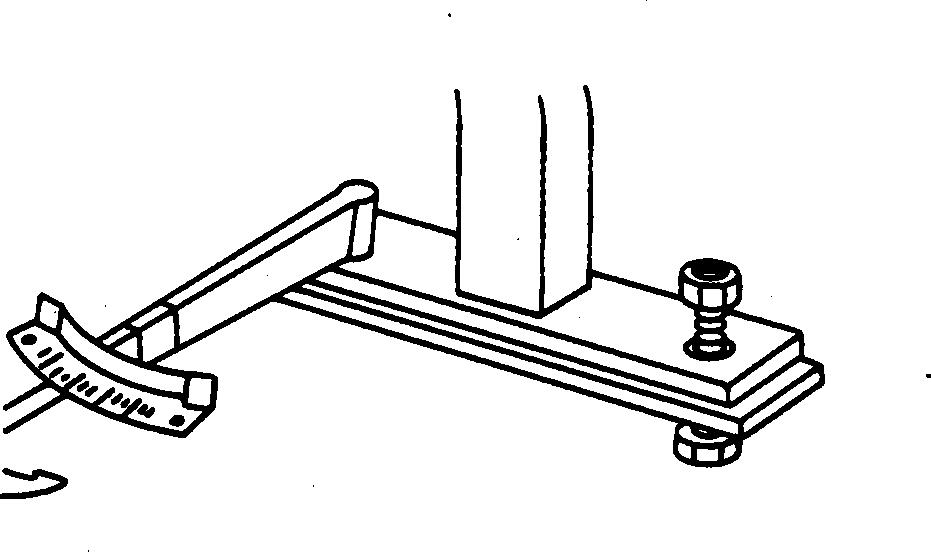
LX001317 UN 25JUL94
Is the oil level too low?
Possible causes:
• Improper service intervals
• External leaks (loss of oil)
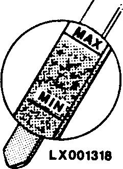
LX001318 UN 25JUL94
Is the oil milky or dirty?
Possible causes:
• Water in oil (milky).
• Filter failure (dirty)
• Mechanical failure (metallic particles)


LX001319 UN 25JUL94
Is the oil discoloured or does it smell burnt (overheated oil)?
Possible causes:
• Internal leaks
• Bent oil lines
• Plugged oil cooler
• Incorrect oil viscosity
• Mechanical failure Continued
OK: GO TO 3.
NOTOK: Rectify the fault.
LX25601,0000716 -19-17OCT06-4/6
General References
NOTE: If possible, do this check with the tractor at its operating temperature. Before doing the check, start the engine and, one after the other, deliberately engage and disengage all tractor components such as steering, hitch, SCVs, brakes, differential lock, front-wheel drive and PTO.
LX1021428 UN 22JUN99
Possible causes:
• Broken lines, ruptured hoses or loose connections
• Cracks or porous areas in the housing
• Leaks at shaft sealing rings, O-rings or gaskets
OK: GO TO 4.
NOTOK: Rectify the fault.
LX25601,0000716 -19-17OCT06-5/6
4
CAUTION: Make sure that the tractor will remain immobilized for the duration of the test. Move the gear-shift lever to its "park" position and the range shift lever to its "neutral" position.
NOTE: If possible, do this check with the tractor at its operating temperature.

LX1021429 UN 17JUN99
Start the engine and run it at a speed of 1000 rpm. Deliberately engage and disengage all tractor components such as steering, rockshaft, SCVs, brakes, differential lock, front-wheel drive and PTO.
• Be alert for gurgling noises, overheated oil lines or components, and for any other conditions that could indicate a problem or help identify it.
Possible causes:
• Internal leaks
• Bent oil lines
• Plugged oil cooler
• Incorrect oil viscosity

• Mechanical failure OK: Introductory checks completed.
LX25601,0000716 -19-17OCT06-6/6
General Information - Inch Bolt and Cap Screws, Torque Values
a Grade 2 applies for hex cap screws up to 6 in. (152 mm) long. Grade 1 applies for hex cap screws over 6 in. (152 mm) long, and for all other types of bolts and screws of any length.
b "Lubricated" means coated with a lubricant such as engine oil, or fasteners with phosphate and oil coatings.
c "Dry" means plain or zinc-plated without any lubrication.
DO NOT use these values if a different torque value or tightening procedure is given for a specific application. Torque values listed are for general use only. Torque values listed are for general use only.
Shear bolts are designed to fail under predetermined loads. Always replace shear bolts with identical grade.
Fasteners should be replaced with the same or higher grade. If higher grade fasteners are used, these should only be tightened to the strength of the original.
Make sure fastener threads are clean and you properly start thread engagement. This will prevent them from failing when tightening.
Tighten plastic insert or crimped steel-type lock nuts to approximately 50 percent of the dry torque shown in the chart, applied to the nut, not to the bolt head. Tighten toothed or serrated-type lock nuts to the full torque value.

General References
General Information - Metric Bolt and Cap Screws, Torque Values
"Lubricated" means coated with a lubricant such as engine oil, or fasteners with phosphate and oil coatings.
"Dry" means plain or zinc-plated without any lubrication.
DO NOT use these values if a different torque value or tightening procedure is given for a specific application. Torque values listed are for general use only. Torque values listed are for general use only.
Shear bolts are designed to fail under predetermined loads. Always replace shear bolts with identical grade.
Fasteners should be replaced with the same or higher grade. If higher grade fasteners are used, these should only be tightened to the strength of the original.
Make sure fastener threads are clean and you properly start thread engagement. This will prevent them from failing when tightening.
Tighten plastic insert or crimped steel-type lock nuts to approximately 50 percent of the dry torque shown in the chart, applied to the nut, not to the bolt head. Tighten toothed or serrated-type lock nuts to the full torque value.

General Information - Hydraulic System Inch Fittings, Torque Values

The torques in the table above are intended only as approximate values and do NOT apply if a different torque value is listed for specific fittings at other points in this manual. Check fittings regularly to make sure they are seated properly.
When replacing fittings, be sure to use parts with an equal or higher grade to the parts you are replacing. Items of
hardware (e.g. union nuts) that are of a higher grade should be tightened to the same torque value as the parts they replace.
It is vitally important to make sure that the sealing faces are clean and that the O-rings have been inserted properly.
General Information - Hydraulic System Metric Fittings, Torque Values

The torques in the table above are intended only as approximate values and do NOT apply if a different torque value is listed for specific fittings at other points in this manual. Check fittings regularly to make sure they are seated properly.
When replacing fittings, be sure to use parts with an equal or higher grade to the parts you are replacing. Items of
hardware (e.g. union nuts) that are of a higher grade should be tightened to the same torque value as the parts they replace.
It is vitally important to make sure that the sealing faces are clean and that the O-rings have been inserted properly.