550G, 555G, 650G
TECHNICAL MANUAL

450G, 455G, 550G, 555G, 650G Crawler Repair
TM1404 14JUN11 (ENGLISH)
For complete service information also see:
450G, 455G,
Crawler Repair
450G, 455G, 550G, 555G, 650G Operation and Test (Complete) TM1403 450G, 455G, 550G, 555G, 650G Repair (Complete)................................................ TM1404 Worldwide Construction And Forestry Division LITHO IN U.S.A.
Foreword
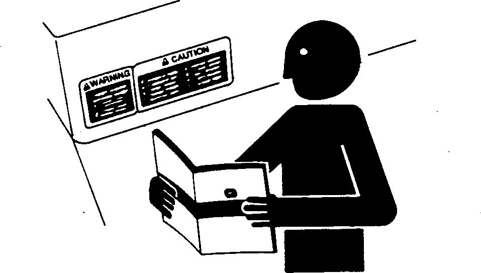
This manual is written for an experienced technician. Essential tools required in performing certain service work are identified in this manual and are recommended for use.
Live with safety: Read the safety messages in the introduction of this manual and the cautions presented throughout the text of the manual.
This is the safety-alert symbol. When you see this symbol on the machine or in this manual, be alert to the potential for personal injury.

Technical manuals are divided in two parts: repair and operation and tests. Repair sections tell how to repair the components. Operation and tests sections help you identify the majority of routine failures quickly.
Information is organized in groups for the various components requiring service instruction. At the
Help!! Help!! Help!! Help!!
We need your help to continually improve our technical publications. Please FAX or mail your comments, ideas and improvements.
SEND TO: John Deere Dubuque Works
beginning of each group are summary listings of all applicable essential tools, service equipment and tools, other materials needed to do the job, service parts kits, specifications, wear tolerances, and torque values.
Technical Manuals are concise guides for specific machines. They are on-the-job guides containing only the vital information needed for diagnosis, analysis, testing, and repair.
Fundamental service information is available from other sources covering basic theory of operation, fundamentals of troubleshooting, general maintenance, and basic type of failures and their causes.
See DB1990 Service Publications Catalog to order a Technical Manual (TM).
TX,450GIFC -19-16SEP93-1/1
P.O. Box 538 Dubuque, Iowa 52004-0538
Dept. 317
Attn: Publications Supervisor
FAX NUMBER: 563-589-5800
tm140400 450G/455G/550G/555G/650G Crawler General Info Repair Manual
Ideas, Comments, (Please state Page Number):
OVERALL, how would you rate the quality of "ALL" Technical Manuals provided to you? (Check one)
Poor Fair Good Very Good Excellent 1 2 3 4 5 6 7 8 9 10
Company Name Address Phone FAX No. Dealer Acct. No.
THANK YOU!
TX,INTR,RB241 -19-22JAN98-1/1
061411 PN=2
TM1404 (14JUN11) G-Series Crawlers
Introduction
Section 00—General Information
Group 0001 Safety Information
Group 0002 General Specifications
Group 0003 Torque Values
Group 0004 Fuels and Lubricants
Section 01 Tracks
Group 0130 Track System
Group 0199 Dealer Fabricated Tools
Section 02 Axles and Suspension Systems
Group 0250 Axle Shaft, Bearings, and Reduction Gears
Group 0260 Hydraulic System
Group 0299 Dealer Fabricated Tools
Section 03 Transmission
Group 0315 Control Linkage
Group 0325 Input Drive Shafts and U-Joints
Group 0350 Gears, Shafts, Bearings and Clutch
Group 0360 Hydraulic System
Group 0399 Dealer Fabricated Tools
Section 04—Engine
Group 0400 Removal and Installation
Section 05 Engine Auxiliary Systems
Group 0505 Cold Weather Starting Aid
Group 0510 Cooling System
Group 0515 Speed Controls and Fuel Shut-Off Linkage
Group 0520 Intake System
Group 0560 External Fuel Supply System
Section 06—Torque Converter
Group 0600 Removal and Installation
Group 0651 Turbine, Gears and Shaft
Section 07
Dampener Drive
Group 0700 Removal and Installation
Section 09 Steering Systems
Group 0920 Power Steering Linkage
Group 0960
Hydraulic System
Section 16—Electrical System
Group 1671 Batteries, Support and Cables
Group 1672 Alternator, Regulator, and Charging System Wiring
Group 1673 Lighting System
Group 1674 Wiring Harness and Switches
Group 1676 Instruments and Indicators
Group 1677 Motors and Actuators
Section 17—Frames, Chassis, or Supporting Structure
Group 1740 Frame Installation
Group 1749 Chassis Weights
Group 1799 Dealer Fabricated Tools
Section 18 Operator’s Station
Group 1800 Removal and Installation
Group 1821 Seat and Seat Belt
Section 19 Sheet Metal and Styling
Group 1910 Hood and Engine Enclosure
Group 1913 Miscellaneous Guards
Group 1921 Grille and Grille Housing
Group 1927 Fenders
Section 20—Safety, Convenience and Miscellaneous
Group 2004 Horn and Warning Devices
Section 21—Main Hydraulic System
Group 2160 Hydraulic System
Section 31—Loader
Group 3102 Bucket
Group 3115 Controls Linkage
Group 3140 Frames
Group 3160 Hydraulics
Section 32 Bulldozer
Group 3201 Blades
Group 3215 Controls Linkage
Group 3240 Frames
Group 3260 Hydraulic System
Section 33—Backhoe
Group 3300 Removal and Installation
Group 3302 Buckets
Group 3315 Controls Linkage
Group 3340 Frames
Group 3360 Hydraulic System
Original Instructions. All information, illustrations and specifications in this manual are based on the latest information available at the time of publication. The right is reserved to make changes at any time without notice.
061411 PN=1
COPYRIGHT © 2011 DEERE & COMPANY Moline, Illinois All rights reserved. A John Deere ILLUSTRUCTION ® Manual Previous Editions Copyright © 1998, 1993,1992,1991,1988,1987,2003 TM1404 (14JUN11) i G-Series Crawlers Contents
Contents 061411 PN=2 TM1404 (14JUN11) ii
G-Series Crawlers
061411 PN=1 Contents Section 00 General Information Group 0001 Safety Information Page 550G LGP Drain and Refill Page Handle Fluids Safely Avoid Fires 00-0001-1 Prevent Battery Explosions 00-0001-1 Prepare for Emergencies 00-0001-1 Prevent Acid Burns........................................00-0001-2 Handle Chemical Products Safely 00-0001-2 Avoid High-Pressure Fluids 00-0001-3 Park Machine Safely 00-0001-3 Support Machine Properly 00-0001-3 Wear Protective Clothing 00-0001-4 Work in Clean Area........................................00-0001-4 Service Machines Safely...............................00-0001-4 Work In Ventilated Area.................................00-0001-5 Illuminate Work Area Safely 00-0001-5 Replace Safety Signs 00-0001-5 Use Proper Lifting Equipment 00-0001-6 Remove Paint Before Welding or Heating 00-0001-6 Avoid Heating Near Pressurized Fluid Lines ..................................................00-0001-6 Keep ROPS Installed Properly 00-0001-7 Service Tires Safely 00-0001-7 Avoid Harmful Asbestos Dust 00-0001-8 Practice Safe Maintenance 00-0001-8 Use Proper Tools 00-0001-9 Dispose of Waste Properly............................00-0001-9 Live With Safety 00-0001-9 Group 0002 General Specifications 450G Crawler Dozer Specifications 00-0002-1 450G Drain and Refill Capacities 00-0002-3 450G LT Crawler Dozer Specifications.............................................00-0002-4 450G LT Drain and Refill Capacities 00-0002-6 450G LGP Crawler Dozer Specifications 00-0002-7 450G LGP Drain and Refill Capacities...................................................00-0002-9 455G Crawler Loader Specifications 00-0002-10 455G Crawler Loader Specifications cont. 00-0002-12 455G Drain and Refill Capacities 00-0002-12 550G LT Crawler Dozer Specifications 00-0002-13 550G LT Drain and Refill Capacities 00-0002-15 550G LGP Crawler Dozer Specifications 00-0002-16 Capacities 00-0002-18 555G Crawler Loader Specifications 00-0002-19 555G Drain and Refill Capacities 00-0002-21 650G Crawler Dozer Specifications...........................................00-0002-22 650G Drain and Refill Capacities ...............00-0002-24 650G LGP Crawler Dozer Specifications 00-0002-25 650G LGP Drain and Refill Capacities ................................................00-0002-27 9310 Backhoe Specifications 00-0002-27 9310 Backhoe Lift Capacity (G Series Loaders).......................................00-0002-28 9310 Backhoe Lift Capacity (G-Series Dozers) 00-0002-29 Group 0003 Torque Values Specifications 00-0003-1 Hardware Torque Specifications 00-0003-1 ROPS Torque Specifications........................ 00-0003-1 Checking Track Shoe Cap Screw Torque 00-0003-2 Unified Inch Bolt and Screw Torque Values......................................................... 00-0003-3 Metric Bolt and Screw Torque Values......................................................... 00-0003-4 Additional Metric Cap Screw Torque Values 00-0003-5 Check Oil Lines And Fittings 00-0003-6 Service Recommendations for 37° Flare and 30° Cone Seat Connectors 00-0003-6 Service Recommendations for O-Ring Boss Fittings................................. 00-0003-7 Service Recommendations For Flat Face O-Ring Seal Fittings 00-0003-8 Service Recommendations For Inch Series Four Bolt Flange Fittings 00-0003-9 Service Recommendations for Metric Series Four Bolt Flange Fitting 00-0003-10 Group 0004 Fuels and Lubricants Fuel Specifications 00-0004-1 Storing Fuel 00-0004-1 Do Not Use Galvanized Containers............00-0004-1 Diesel Engine Oil........................................... 00-0004-2 Final Drive Oil 00-0004-3 Continued on next page TM1404 (14JUN11) 00-1 G-Series Crawlers
Contents 061411 PN=2 Track Roller, Front Idler, and Page Carrier Roller Oil........................................ 00-0004-3 Transmission, Steering Clutches, Hydraulic and Winch Oil 00-0004-4 Grease 00-0004-5 Heavy Duty Diesel Engine Coolant 00-0004-6 Alternative and Synthetic Lubricants 00-0004-6 Lubricant Storage 00-0004-7
PN=7
TM1404 (14JUN11)
00-2
G-Series Crawlers
Handle Fluids Safely Avoid Fires
When you work around fuel, do not smoke or work near heaters or other fire hazards.

Store flammable fluids away from fire hazards. Do not incinerate or puncture pressurized containers. Make sure machine is clean of trash, grease, and debris.
Do not store oily rags; they can ignite and burn spontaneously.
Prevent Battery Explosions
Keep sparks, lighted matches, and open flame away from the top of battery. Battery gas can explode.
Never check battery charge by placing a metal object across the posts. Use a volt-meter or hydrometer.
Do not charge a frozen battery; it may explode. Warm battery to 16°C (60°F).
Prepare for Emergencies
Be prepared if a fire starts.
Keep a first aid kit and fire extinguisher handy. Keep emergency numbers for doctors, ambulance service, hospital, and fire department nearyour telephone.
Contents 061411 PN=2 061411
(14JUN11) 00-0001-1
TM1404
G-Series Crawlers
Group 0001 Safety Information
DX,FLAME -19-29SEP98-1/1
DX,SPARKS -19-03MAR93-1/1
TS291 UN 23AUG88 TS204 UN 23AUG88 TS227 UN 23AUG88
DX,FIRE2 -19-03MAR93-1/1
Prevent Acid Burns
Sulfuric acid in battery electrolyte is poisonous. It is strong enough to burn skin, eat holes in clothing, and cause blindness if splashed into eyes.
Avoid the hazard by:
1. Filling batteries in a well-ventilated area.
2. Wearing eye protection and rubber gloves.
3. Avoiding breathing fumes when electrolyte is added.
4. Avoiding spilling or dripping electrolyte.
5. Use proper jump start procedure.
If you spill acid on yourself:
1. Flush your skin with water.
2. Apply baking soda or lime to help neutralize the acid.
3. Flush your eyes with water for 15 30 minutes. Get medical attention immediately.
If acid is swallowed:
1. Do not induce vomiting.
2. Drink large amounts of water or milk, but do not exceed 2 L (2 quarts).
3. Get medical attention immediately.
Handle Chemical Products Safely
Direct exposure to hazardous chemicals can cause serious injury. Potentially hazardous chemicals used with John Deere equipment include such items as lubricants, coolants, paints, and adhesives.
A Material Safety Data Sheet (MSDS) provides specific details on chemical products: physical and health hazards, safety procedures, and emergency response techniques.
Check the MSDS before you start any job using a hazardous chemical. That way you will know exactly what the risks are and how to do the job safely. Then follow procedures and recommended equipment.
(See your John Deere dealer for MSDS’s on chemical products used with John Deere equipment.)

Safety Information PN=8 061411 TM1404 (14JUN11) 00-0001-2 G-Series Crawlers
DX,POISON -19-21APR93-1/1
TS1132 UN 26NOV90 TS203 UN 23AUG88
DX,MSDS,NA -19-03MAR93-1/1
Avoid High-Pressure Fluids
Escaping fluid under pressure can penetrate the skin causing serious injury.
Avoid the hazard by relieving pressure before disconnecting hydraulic or other lines. Tighten all connections before applying pressure.
Search for leaks with a piece of cardboard. Protect hands and body from high-pressure fluids.
If an accident occurs, see a doctor immediately. Any fluid injected into the skin must be surgically removed within a few hours or gangrene may result. Doctors unfamiliar with this type of injury should reference a knowledgeable medical source. Such information is available in English from Deere & Company Medical Department in
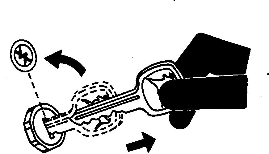
Park Machine Safely
Before working on the machine:
• Lower all equipment to the ground.
• Stop the engine and remove the key.
• Disconnect the battery ground strap.
• Hang a "DO NOT OPERATE" tag in operator station.
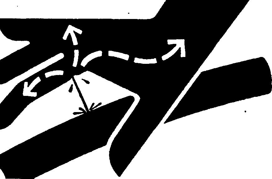
Moline, Illinois, U.S.A., by calling 1-800-822-8262 or +1 309-748-5636.
DX,FLUID -19-20AUG09-1/1
Support Machine Properly
Always lower the attachment or implement to the ground before you work on the machine. If the work requires that the machine or attachment be lifted, provide secure support for them. If left in a raised position, hydraulically supported devices can settle or leak down.
Do not support the machine on cinder blocks, hollow tiles, or props that may crumble under continuous load. Do not work under a machine that is supported solely by a jack. Follow recommended procedures in this manual.
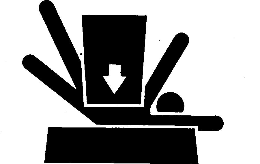
When implements or attachments are used with a machine, always follow safety precautions listed in the implement or attachment operator’s manual.
-19-04JUN90-1/1
PN=9 061411
Safety Information
TM1404 (14JUN11) 00-0001-3 G-Series
Crawlers
DX,PARK
TS229 UN 23AUG88 TS230 UN 24MAY89 X9811 UN 23AUG88
DX,LOWER -19-24FEB00-1/1
Wear Protective Clothing
Wear close fitting clothing and safety equipment appropriate to the job.

Operating equipment safely requires the full attention of the operator. Do not wear radio or music headphones while operating machine.
Work in Clean Area
Before starting a job:
• Clean work area and machine.
• Make sure you have all necessary tools to do your job.
• Have the right parts on hand.
• Read all instructions thoroughly; do not attempt shortcuts.
Service Machines Safely
Tie long hair behind your head. Do not wear a necktie, scarf, loose clothing, or necklace when you work near machine tools or moving parts. If these items were to get caught, severe injury could result.

Remove rings and other jewelry to prevent electrical shorts and entanglement in moving parts.

Information PN=10 061411 TM1404 (14JUN11) 00-0001-4
Safety
G-Series Crawlers
DX,WEAR2 -19-03MAR93-1/1
DX,CLEAN -19-04JUN90-1/1
TS228 UN 23AUG88 T6642EJ UN 18OCT88 TS206 UN 23AUG88
DX,LOOSE -19-04JUN90-1/1
Safety Information
Work In Ventilated Area
Engine exhaust fumes can cause sickness or death. If it is necessary to run an engine in an enclosed area, remove the exhaust fumes from the area with an exhaust pipe extension.
If you do not have an exhaust pipe extension, open the doors and get outside air into the area.
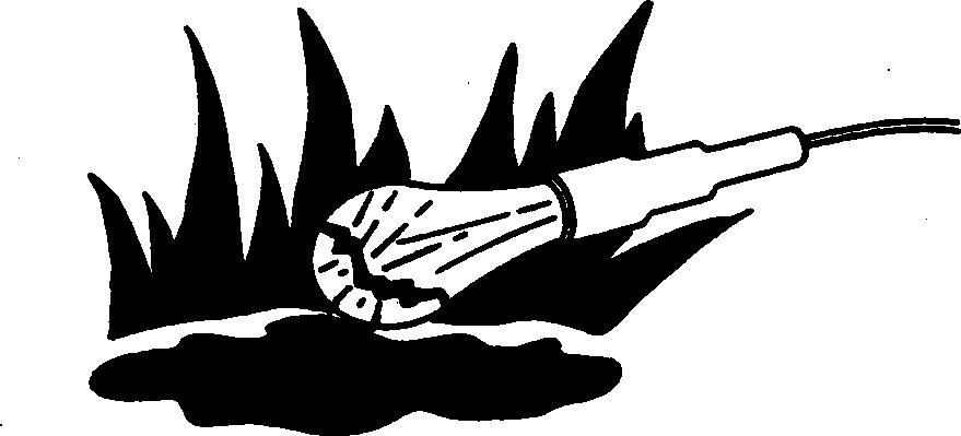
Illuminate Work Area Safely
Illuminate your work area adequately but safely. Use a portable safety light for working inside or under the machine. Make sure the bulb is enclosed by a wire cage. The hot filament of an accidentally broken bulb can ignite spilled fuel or oil.
Replace Safety Signs
Replace missing or damaged safety signs. See the machine operator’s manual for correct safety sign placement.
PN=11 061411
TM1404 (14JUN11)
00-0001-5
G-Series Crawlers
DX,AIR -19-17FEB99-1/1
DX,LIGHT -19-04JUN90-1/1
TS201 UN 23AUG88 TS223 UN 23AUG88 TS220 UN 23AUG88
DX,SIGNS1 -19-04JUN90-1/1
Use Proper Lifting Equipment
Lifting heavy components incorrectly can cause severe injury or machine damage.

Follow recommended procedure for removal and installation of components in the manual.
Remove Paint Before Welding or Heating
Avoid potentially toxic fumes and dust.
Hazardous fumes can be generated when paint is heated by welding, soldering, or using a torch.
Remove paint before heating:
• Remove paint a minimum of 100 mm (4 in.) from area to be affected by heating. If paint cannot be removed, wear an approved respirator before heating or welding.
• If you sand or grind paint, avoid breathing the dust. Wear an approved respirator.
• If you use solvent or paint stripper, remove stripper with soap and water before welding. Remove solvent or paint stripper containers and other flammable material from area. Allow fumes to disperse at least 15 minutes before welding or heating.
Do not use a chlorinated solvent in areas where welding will take place.
Avoid Heating Near Pressurized Fluid Lines
Flammable spray can be generated by heating near pressurized fluid lines, resulting in severe burns to yourself and bystanders. Do not heat by welding, soldering, or using a torch near pressurized fluid lines or other flammable materials. Pressurized lines can accidentally burst when heat goes beyond the immediate flame area.

Do all work in an area that is well ventilated to carry toxic fumes and dust away.
Dispose of paint and solvent properly.
Safety Information PN=12 061411
TM1404 (14JUN11) 00-0001-6 G-Series Crawlers
DX,PAINT -19-24JUL02-1/1
DX,LIFT -19-04JUN90-1/1
TS953 UN 15MAY90 TS220 UN 23AUG88 TS226 UN 23AUG88
DX,TORCH -19-10DEC04-1/1
Keep ROPS Installed Properly
Make certain all parts are reinstalled correctly if the roll-over protective structure (ROPS) is loosened or removed for any reason. Tighten mounting bolts to proper torque.
The protection offered by ROPS will be impaired if ROPS is subjected to structural damage, is involved in an overturn incident, or is in any way altered by welding, bending, drilling, or cutting. A damaged ROPS should be replaced, not reused.
Service Tires Safely
Explosive separation of a tire and rim parts can cause serious injury or death.
Do not attempt to mount a tire unless you have the proper equipment and experience to perform the job.
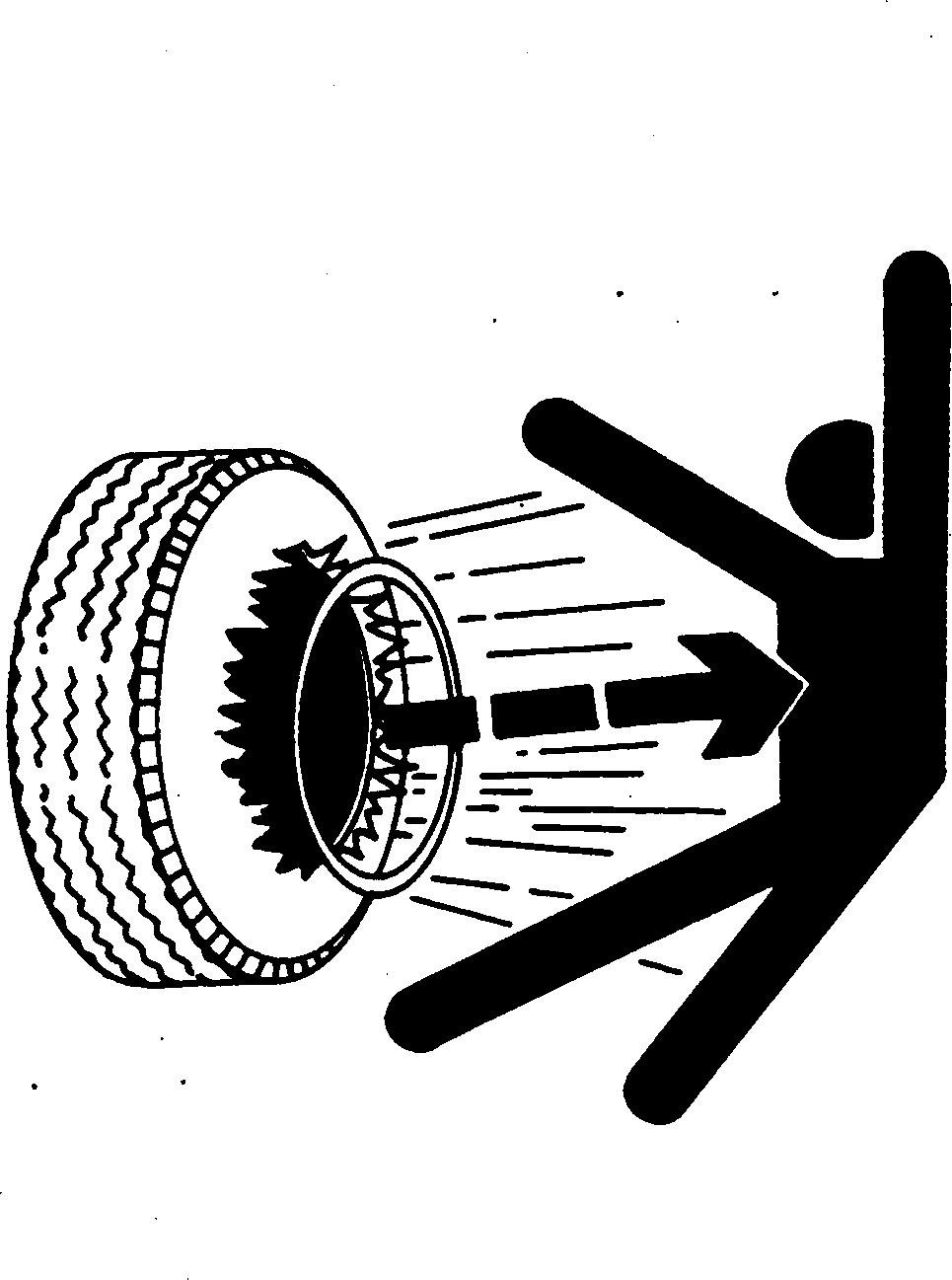
Always maintain the correct tire pressure. Do not inflate the tires above the recommended pressure. Never weld or heat a wheel and tire assembly. The heat can cause an increase in air pressure resulting in a tire explosion. Welding can structurally weaken or deform the wheel.
When inflating tires, use a clip-on chuck and extension hose long enough to allow you to stand to one side and NOT in front of or over the tire assembly. Use a safety cage if available.
Check wheels for low pressure, cuts, bubbles, damaged rims or missing lug bolts and nuts.
Information PN=13 061411
Safety
TM1404 (14JUN11)
00-0001-7
G-Series Crawlers
DX,ROPS3 -19-03MAR93-1/1
TS211 UN 23AUG88 TS212 UN 23AUG88
DX,RIM -19-24AUG90-1/1
Safety Information
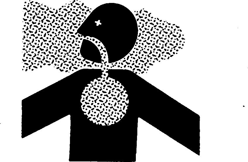
Avoid Harmful Asbestos Dust

Avoid breathing dust that may be generated when handling components containing asbestos fibers. Inhaled asbestos fibers may cause lung cancer.
Components in products that may contain asbestos fibers are brake pads, brake band and lining assemblies, clutch plates, and some gaskets. The asbestos used in these components is usually found in a resin or sealed in some way. Normal handling is not hazardous as long as airborne dust containing asbestos is not generated.
Avoid creating dust. Never use compressed air for cleaning. Avoid brushing or grinding material containing asbestos. When servicing, wear an approved respirator. A special vacuum cleaner is recommended to clean asbestos. If not available, apply a mist of oil or water on the material containing asbestos.
Practice Safe Maintenance
Understand service procedure before doing work. Keep area clean and dry.
Never lubricate, service, or adjust machine while it is moving. Keep hands, feet , and clothing from power-driven parts. Disengage all power and operate controls to relieve pressure. Lower equipment to the ground. Stop the engine. Remove the key. Allow machine to cool.
Securely support any machine elements that must be raised for service work.
Keep all parts in good condition and properly installed. Fix damage immediately. Replace worn or broken parts. Remove any buildup of grease, oil, or debris.
On self-propelled equipment, disconnect battery ground cable (-) before making adjustments on electrical systems or welding on machine.
On towed implements, disconnect wiring harnesses from tractor before servicing electrical system components or welding on machine.
PN=14 061411
Keep bystanders away from the area.
TM1404 (14JUN11) 00-0001-8 G-Series Crawlers
DX,DUST -19-15MAR91-1/1
TS218 UN 23AUG88 TS220 UN 23AUG88
DX,SERV -19-17FEB99-1/1
Use Proper Tools
Use tools appropriate to the work. Makeshift tools and procedures can create safety hazards.
Use power tools only to loosen threaded parts and fasteners.
For loosening and tightening hardware, use the correct size tools. DO NOT use U.S. measurement tools on metric fasteners. Avoid bodily injury caused by slipping wrenches.

Use only service parts meeting John Deere specifications.
Dispose of Waste Properly
Improperly disposing of waste can threaten the environment and ecology. Potentially harmful waste used with John Deere equipment include such items as oil, fuel, coolant, brake fluid, filters, and batteries.
Use leakproof containers when draining fluids. Do not use food or beverage containers that may mislead someone into drinking from them.
Do not pour waste onto the ground, down a drain, or into any water source.
Air conditioning refrigerants escaping into the air can damage the Earth’s atmosphere. Government regulations may require a certified air conditioning service center to recover and recycle used air conditioning refrigerants.
Inquire on the proper way to recycle or dispose of waste from your local environmental or recycling center, or from your John Deere dealer.

Live With Safety
Before returning machine to customer, make sure machine is functioning properly, especially the safety systems. Install all guards and shields.

PN=15 061411 TM1404 (14JUN11) 00-0001-9
Safety Information
G-Series Crawlers
DX,REPAIR -19-17FEB99-1/1
DX,DRAIN -19-03MAR93-1/1
DX,LIVE
TS231 19 07OCT88 TS1133 UN 26NOV90 TS779 UN 08NOV89
-19-25SEP92-1/1
Group 0002
General Specifications
450G Crawler Dozer Specifications
NOTE: Specifications and design subject to change without notice. Whenever applicable, specifications are in accordance with ICED and SAE standards. Except where otherwise noted, these specifications are based on a unit with roll-over protective
structure, full fuel tank, 80 kg (175 lb) operator, and standard equipment.
Blade capacity shown is for a 2230 mm (7 ft 3.8 in.) blade. All blades are interchangeable between the 450G, 550G, and the 650G.
PN=16 061411
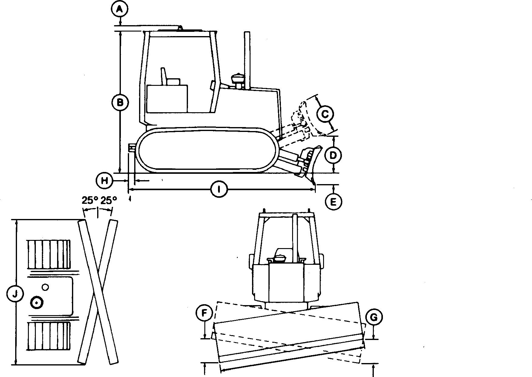
Item Measurement Specification Operator Weight 80 kg (175 lb) Blade Angled Width 2230 mm (7 ft 3.8 in.) A Canopy extension 60 mm (2.4 in.) B Canopy height 2.70 m (8 ft 10 in.) C Blade height 827 mm (2 ft 8.6 in.) D Blade lift height 815 mm (2 ft 8.1 in.) E Digging depth 504 mm (1 ft 7.9 in.) F Blade tilt (right side): Standard blade Wide blade 330 mm (1 ft 1 in.) 391 mm (1 ft 3.4 in.) G Blade tilt (left side): Standard blade Wide blade 330 mm (1 ft 1 in.) 391 mm (1 ft 3.4 in.) H Drawbar extension 280 mm (11 in.) I Overall length 3917 mm (12 ft 10.2 in.) J Blade width: Standard blade (angled width) Wide blade (angled width) Standard Wide 2230 mm (7 ft 3.8 in.) 2686 mm (8 ft 9.7 in.) 2464 mm (8 ft 1 in.) 2921 mm (9 ft 7 in.) Continued on next page TX,115,FF1816 -19-12JAN93-1/2 TM1404 (14JUN11) 00-0002-1 G-Series Crawlers
T7347AC UN 23JUL90
General Specifications
Engine: John Deere 4045D (Direct Drive only) or 4045T (S.N. 840460) or John Deere PowerTech 4.5L engine type 4045TT061 (S.N. 840461 )
Transmission:
(4F-4R) with torque converter or direct drive. Full power shift, Dura-Shift with torque converter or direct drive, designed and built by John Deere. You can power shift easily from one gear to another as conditions change without stopping the machine or using a clutch. Power control inching pedal adds versatility. Four speeds forward and reverse allow the operator to match speeds to the working conditions.
PN=17
061411 Track gauge: 1450 mm (57 in.) Blade capacity: Standard blade 1.3 m 3 (1.63 yd 3 ) Wide blade 1.6 m 3 (2.1 yd 3 )
Type Naturally aspirated (4045D)
compensating turbocharge (4045T) Bore and stroke 106.5 x 127 mm (4.19 x 5.00 in.) No. of cylinders 4 Fuel consumption, typical (S.N. 840460) 4.9 to 8.7 L/h (5 to 2.3 gal/hr) Fuel consumption, typical (S.N. 840461 ) 6.3 to 9.5 L/h (1.7 to 2.5 gal/hr) Compression ratio (S.N. 840460) 17.8 to 1 Compression ratio (S.N. 840461 ) 17 to 1 Electrical system 12 volt (with battery disconnect switch, if equipped) Battery 12 volt Alternator 65 amp SAE net power at 2100 rpm SAE gross power at 2100 rpm 52 kW (70 hp) 54.5 kW (73 hp) Maximum net torque at 1300 rpm 309 N∙m (228 lb-ft) Drawbar 38 kW (51 hp) Displacement (S.N. 840460) 4.524 L (276 cu in.) Displacement (S.N. 840461 ) 4.5 L
altitude
Hydraulic pump: Gear Pressure 18 961 kPa (2750 psi) Flow at 2100 rpm 64 L/min (17 gpm) Steering: Clutches Wet multiple disk Brakes Wet band Undercarriage: Grouser, closed-center 406 mm (16 in.) Track shoes, each side 37 Ground contact area 15 690 cm 2 (2432 in. 2 ) Ground pressure (direct drive) 44.6 kPa (6.47 psi) Ground pressure (torque converter) 45.2 kPa (6.55 psi) Operating Weight (with ROPS): Direct Drive 7152 kg (15 732 lb) Torque Converter 7243 kg (15 932 lb) 450G TC with Wide Shoes (Direct Drive) 7586 kg (16 688 lb) 450G TC with Wide Shoes (Torque Converter) 7677 kg (16 888 lb) TX,115,FF1816 -19-12JAN93-2/2 TM1404 (14JUN11) 00-0002-2 G-Series Crawlers
Powershift
General Specifications
450G Drain and Refill Capacities
PN=18
TX,115,FF1917 -19-08OCT93-1/1 061411 Metric English Fuel tank 155 L 41 gal Engine coolant 17 L 18 qt Engine oil, including filter change (S.N. 840460) 8.5 L 9 qt Engine oil, including filter change (S.N. 840461 ) 14 L 14.8 qt Transmission: Transmission, direct drive (S.N. 790984) 80.25 L 21.2 gal add 34 L (9 gal) w/winch if equipped Transmission, direct drive (S.N. 790985 ) 102 L 27 gal add 34 L (9 gal) w/winch if equipped Transmission, torque converter 102 L 27 gal add 34 L (9 gal) w/winch if equipped Hydraulic reservoir 38 L 10 gal Hydraulic system 55.3 L 14.6 gal Final drive (each side) 6.6 L 7 qt TM1404 (14JUN11) 00-0002-3 G-Series Crawlers
General Specifications
450G LT Crawler Dozer Specifications
NOTE: Specifications and design subject to change without notice. Whenever applicable, specifications are in accordance with ICED and SAE standards. Except where otherwise noted, these specifications are based on a unit with roll-over protective
structure, full fuel tank, 80 kg (175 lb) operator, and standard equipment.
Blade capacity shown is for a 2230 mm (7 ft 3.8 in.) blade. All blades are interchangeable between the 450G, 550G, and the 650G.
PN=19 061411
Item Measurement Specification Operator Weight 80 kg (175 lb) Blade Angled Width 2230 mm (7 ft 3.8 in.) A Canopy extension 60 mm (2.4 in.) B Canopy height 2.70 m (8 ft 10 in.) C Blade height 827 mm (2 ft 8.6 in.) D Blade lift height 815 mm (2 ft 8.1 in.) E Digging depth 504 mm (1 ft 7.9 in.) F Blade tilt (right side): Standard blade Wide blade 330 mm (1 ft 1 in.) 391 mm (1 ft 3.4 in.) G Blade tilt (left side): Standard blade Wide blade 330 mm (1 ft 1 in.) 391 mm (1 ft 3.4 in.) H Drawbar extension 280 mm (11 in.) I Overall length 3917 mm (12 ft 10.2 in.) J Blade width: Standard blade (angled width) Wide blade (angled width) Standard Wide 2230 mm (7 ft 3.8 in.) 2686 mm (8 ft 9.7 in.) 2464 mm (8 ft 1 in.) 2921 mm (9 ft 7 in.) Continued on next page TX,115,FF1816 -19-12JAN93-1/2 TM1404 (14JUN11) 00-0002-4 G-Series Crawlers T7347AC UN 23JUL90
General Specifications
Engine: John Deere 4045D (Direct Drive only) or 4045T (S.N. 840460) or John Deere PowerTech 4.5L engine type 4045TT061 (S.N. 840461 )
altitute
Transmission: Powershift (4F-4R) with torque converter or direct drive. Full power shift, Dura-Shift with torque converter or direct drive, designed and built by John Deere. You can power shift easily from one gear to another as conditions change without stopping the machine or using a clutch. Power control inching pedal adds versatility. Four speeds forward and reverse allow the operator to match speeds to the working conditions.
PN=20 061411 Track gauge: 1450 mm (57 in.) Blade capacity: Standard blade 1.3 m 3 (1.63 yd 3 ) Wide blade 1.6 m 3 (2.1 yd 3 )
Type Naturally aspirated (4045D) or
compensating turbocharge (4045T) Bore and stroke 106.5 x 127 mm (4.19 x 5.00 in.) No. of cylinders 4 Fuel consumption, typical (S.N. 840460) 4.9 to 8.7 L/h (5 to 2.3 gal/hr) Fuel consumption, typical (S.N. 840461 ) 6.3 to 9.5 L/h (1.7 to 2.5 gal/hr) Compression ratio (S.N. 840460) 17.8 to 1 Compression ratio (S.N. 840461 ) 17 to 1 Electrical system 12 volt (with battery disconnect switch, if equipped) Battery 12 volt Alternator (S.N. 840460) 65 amp Alternator (S.N. 840461 ) 95 amp SAE net power at 2100 rpm SAE gross power at 2100 rpm 52 kW (70 hp) 54.5 kW (73 hp) Maximum net torque at 1300 rpm 309 N∙m (228 lb-ft) Drawbar 38 kW (51 hp) Displacement (S.N. 840460) 4.524 L (276 cu in.) Displacement (S.N. 840461 ) 4.5 L
Hydraulic pump: Gear Pressure 18 961 kPa (2750 psi) Flow at 2100 rpm 64 L/min (17 gpm) Steering: Clutches Wet multiple disk Brakes Wet band Undercarriage: Grouser, closed-center 406 mm (16 in.) Track shoes, each side 40 Ground contact area 17 632 cm 2 (2733 in. 2 ) Ground pressure (direct drive) 41.1 kPa (5.97 psi) Ground pressure (torque converter) 41.7 kPa (6.04 psi) Operating Weight (with ROPS): Direct Drive 7415 kg (16 310 lb) Torque Converter 7505 kg (16 510 lb) TX,115,FF1816 -19-12JAN93-2/2 TM1404 (14JUN11) 00-0002-5 G-Series Crawlers
General Specifications
450G LT Drain and Refill Capacities
PN=21
TX,115,FF1917 -19-08OCT93-1/1 061411 Metric English Fuel tank 155 L 41 gal Engine coolant 17 L 18 qt Engine oil, including filter change (S.N. 840460) 8.5 L 9 qt Engine oil, including filter change (S.N. 840461 ) 14 L 14.8 qt Transmission: Transmission, direct drive (S.N. 790984) 80.25 L 21.2 gal add 34 L (9 gal) w/winch if equipped Transmission, direct drive (S.N.790985 ) 102 L 27 gal add 34 L (9 gal) w/winch if equipped Transmission, torque converter 102 L 27 gal add 34 L (9 gal) w/winch if equipped Hydraulic reservoir 38 L 10 gal Hydraulic system 55.3 L 14.6 gal Final drive (each side) 8.5 L 9 qt TM1404 (14JUN11) 00-0002-6 G-Series Crawlers
General Specifications
450G LGP Crawler Dozer Specifications
NOTE: Specifications and design subject to change without notice. Whenever applicable, specifications are in accordance with ICED and SAE standards. Except where otherwise noted, these specifications are based on a unit with roll-over protective
structure, full fuel tank, 80 kg (175 lb) operator, and standard equipment.
Blade capacity shown is for a 2230 mm (7 ft 3.8 in.) blade. All blades are interchangeable between the 450G, 550G, and the 650G.
PN=22 061411
Item Measurement Specification Operator Weight 80 kg (175 lb) Blade Angled Width 2230 mm (7 ft 3.8 in.) A Canopy extension 60 mm (2.4 in.) B Canopy height 2.70 m (8 ft 10 in.) C Blade height 827 mm (2 ft 8.6 in.) D Blade lift height 815 mm (2 ft 8.1 in.) E Digging depth 504 mm (1 ft 7.9 in.) F Blade tilt (right side): Standard blade Wide blade 330 mm (1 ft 1 in.) 391 mm (1 ft 3.4 in.) G Blade tilt (left side): Standard blade Wide blade 330 mm (1 ft 1 in.) 391 mm (1 ft 3.4 in.) H Drawbar extension 280 mm (11 in.) I Overall length 3917 mm (12 ft 10.2 in.) J Blade width: Standard blade (angled width) Wide blade (angled width) Standard Wide 2230 mm (7 ft 3.8 in.) 2686 mm (8 ft 9.7 in.) 2464 mm (8 ft 1 in.) 2921 mm (9 ft 7 in.) Continued on next page TX,115,FF1816 -19-12JAN93-1/2 TM1404 (14JUN11) 00-0002-7 G-Series Crawlers T7347AC UN 23JUL90
General Specifications
John Deere 4045D (Direct Drive only) or 4045T (S.N. 840460) or John Deere PowerTech 4.5L engine type 4045TT061 (S.N. 840461 )
Transmission: Powershift (4F-4R) with torque converter or direct drive. Full power shift, Dura-Shift with torque converter or direct drive, designed and built by John Deere. You can power shift easily from one gear to another as conditions change without stopping the machine or using a clutch. Power control inching pedal adds versatility. Four speeds forward and reverse allow the operator to match speeds to the working conditions.
PN=23 061411 Track gauge: 1450 mm (57 in.) Blade capacity: Standard blade 1.3 m 3 (1.63 yd 3 ) Wide blade 1.6 m 3 (2.1 yd 3 ) Engine:
Type Naturally aspirated or altitude compensating
Bore and stroke 106.5 x 127 mm (4.19 x 5.00 in.) No. of cylinders 4 Fuel consumption, typical (S.N. 840460) 4.9 to 8.7 L/h (5 to 2.3 gal/hr) Fuel consumption, typical (S.N. 840461 ) 6.3 to 9.5 L/h (1.7 to 2.5 gal/hr) Compression ratio (S.N. 840460) 17.8 to 1 Compression ratio (S.N. 840461 ) 17 to 1 Electrical system 12 volt (with battery disconnect switch, if equipped) Battery 12 volt Alternator 65 amp SAE net power at 2100 rpm SAE gross power at 2100 rpm 52 kW (70 hp) 54.5 kW (73 hp) Maximum net torque at 1300 rpm 309 N∙m (228 lb-ft) Drawbar 38 kW (51 hp) Displacement (S.N. 840460) 4.524 L (276 cu in.) Displacement (S.N. 840461 ) 4.5 L
turbocharge
Hydraulic pump: Gear Pressure 18 961 kPa (2750 psi) Flow at 2100 rpm 64 L/min (17 gpm) Steering: Clutches Wet multiple disk Brakes Wet band Undercarriage: Grouser, closed-center 610 mm (24 in.) Track shoes, each side 40 Ground contact area 26 445 cm 2 (4099 in. 2 ) Ground pressure (direct drive) 29.0 kPa (4.2 psi) Ground pressure (torque converter) 29.3 kPa (4.25 psi) Operating Weight (with ROPS): 450G LGP Direct Drive 7833 kg (17 232 lb) 450G LGP Torque Converter 7924 kg (17 432 lb) TX,115,FF1816
TM1404 (14JUN11) 00-0002-8 G-Series Crawlers
-19-12JAN93-2/2
General Specifications
450G LGP Drain and Refill Capacities
PN=24
TX,115,FF1917 -19-08OCT93-1/1 061411 Metric English Fuel tank 155 L 41 gal Engine coolant 17 L 18 qt Engine oil, including filter change (S.N. 840460) 8.5 L 9 qt Engine oil, including filter change (S.N. 840461 ) 14 L 14.8 qt Transmission: Transmission, direct drive (S.N. 790984) 80.25 L 21.2 gal add 34 L (9 gal) w/winch if equipped Transmission, direct drive (S.N.790985 ) 102 L 27 gal add 34 L (9 gal) w/winch if equipped Transmission, torque converter 102 L 27 gal add 34 L (9 gal) w/winch if equipped Hydraulic reservoir 38 L 10 gal Hydraulic system 55.3 L 14.6 gal Final drive (each side) 8.5 L 9 qt TM1404 (14JUN11) 00-0002-9 G-Series Crawlers
General Specifications
455G Crawler Loader Specifications
NOTE: Specifications and design subject to change without notice. Wherever applicable, specifications are in accordance with ICED and SAE Standards. Except where otherwise noted, these specifications
are based on a machine with roll-over protective structure, full fuel tank, 80 kg (175 lb) operator, and standard equipment.
Includes 2 counterweights. Each counterweight is 50.5 mm (2 in.)
PN=25 061411
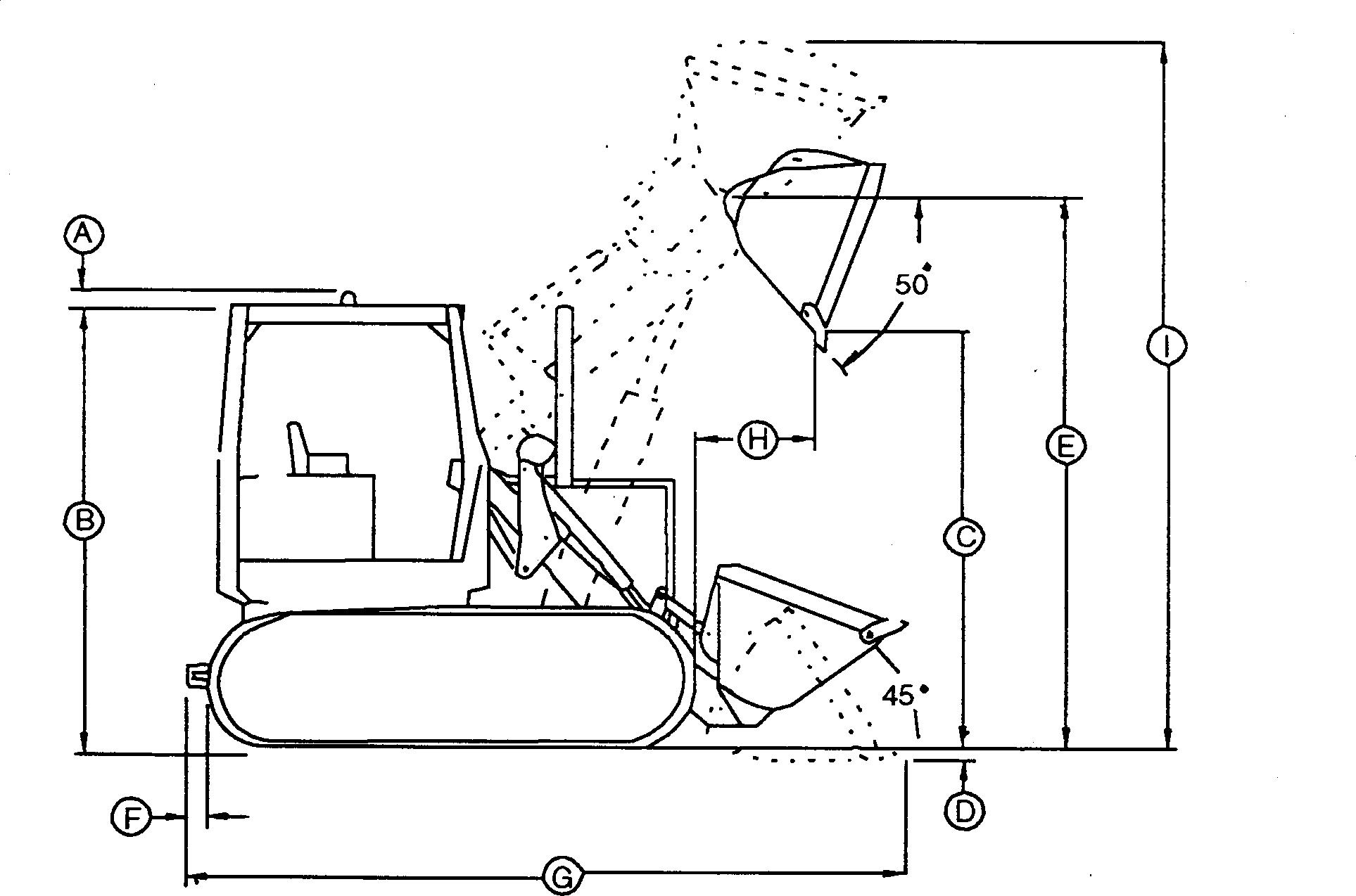
Item Measurement Specification Operator Weight 80 kg (175 lb) Standard Track Wide-Track Multipurpose A Canopy top 60 mm (2.4 in.) 60 mm (2.4 in.) 60 mm (2.4 in.) B Overall height: Standard height ROPS Low-profile ROPS Cab 2708 mm (106.6 in.) 2588 mm (101.9 in.) 2769 mm (109 in.) 2708 mm (106.6 in.) 2588 mm (101.9 in.) 2769 mm (109 in.) 2708 mm (106.6 in.) 2588 mm (101.9 in.) 2769 mm (109 in.) C Dump clearance, maximum height (45° discharge) 2620 mm (103.1 in.) 2635 mm (103.7 in.) 2485 mm (97.8 in.) D Digging depth 135 mm (5.3 in.) 135 mm (5.3 in.) 135 mm (5.3 in.) E Height to hinge pin 3251 mm (128 in.) 3251 mm (128 in.) 3251 mm (128 in.) F Tow bar 533 mm (1 ft 9 in.) 533 mm (1 ft 9 in.) 533 mm (1 ft 9 in.) Ga Overall length 4564 mm (179.7 in.) 4448 mm (175.1 in.) 4638 mm (182.6 in.) H Reach at max height (45°discharge) 871 mm (34.3 in.) 773 mm (30.4 in.) 880 mm (34.6 in.) I Maximum operating height 4285 mm (168.7 in.) 4169 mm (164.1 in.) 4304 mm (169.4 in.) Track gauge: StandardTrack Wide Track 1450 mm (57 in.) 1727 mm (68 in.) a
thick. Engine: Type (S.N. 840460) John Deere 4045T and 4045D Type (S.N. 840461 ) John Deere 4.5 L engine type 4045TT067 Continued on next page TX,9000,RB178 -19-14JUN11-1/2 TM1404 (14JUN11) 00-0002-10 G-Series Crawlers T8196BD UN 14APR94
Transmission: Full power shift, Dura-Shift direct drive transmission is designed and built by John Deere. You can power shift easily from one gear to another as conditions change without stopping the machine or using a clutch. Power control inching pedal adds versatility. Four speeds forward and reverse allow the operator to match speeds to the working conditions.
Specifications PN=26 061411 Rated power at 2100 rpm SAE net 52.2 kW (70 hp) SAE gross 54.5 kW (73 hp) Bore and stroke 106.5 x 127 mm (4.19 x 5.00 in.) No. of cylinders 4 Displacement (S.N. 840460) 4.524 L (276 cu in.) Displacement (S.N. 840461 ) 4.5 L Compression ratio (S.N. 840460) 16.2 to 1 Compression ratio (S.N. 840461 ) 17 to 1 Electrical system 12 volt (with battery disconnect switch if equipped) Alternator 65 amp Maximum net torque at 1300 rpm 309 N∙m (250 lb-ft) Cooling system pressure 69 kPa (10 psi)
General
Hydraulics: Pump Gear Pressure 17 927 kPa (2600 psi) Flow at 2100 rpm 118 L/min (31 gpm) Cylinders: Boom (bore x stroke) 100 mm (3.93 in.) x 827 mm (32.55 in.) Bucket (bore x stroke) 90 mm (3.5 in.) x 744 mm (29.30 in.) Cylinder rod dia. 50 mm (1.96 in.) Steering: Clutches Wet multiple disks Brakes Wet band Undercarriage: Standard Track: Two-bar grouser, closed-center 356 mm (14 in.) Track shoes, each side 37 Ground clearance 330 mm (13 in.) No. of track rollers 5 Ground contact area 13 729 cm 2 (2128 in. 2 ) Ground pressure, Direct Drive 60.1 kPa (8.71 psi) Ground pressure, Torque Converter 60.7 kPa (8.8 psi) Carrier roller 1 Wide Track: Two-bar grouser, closed center 533 mm (21 in.) Track shoes, each side 37 Ground clearance 330 mm (13 in.) No. of track rollers 5 Ground contact area 20 595 cm 2 (3192 in. 2 ) Ground pressure, Direct Drive 41.8 kPa (6.06 psi) Ground pressure, Torque Converter 42.2 kPa (6.12 psi) Carrier roller 1 TX,9000,RB178 -19-14JUN11-2/2 TM1404 (14JUN11) 00-0002-11 G-Series Crawlers
General Specifications
455G Crawler Loader Specifications cont.
aWith three counterweights, zero sprocket weight
bWith four counterweights and two spocket weights
455G Drain and Refill Capacities
PN=27
TX,115,RR3026 -19-14APR94-1/1
TX,115,RR3044 -19-14APR94-1/1 061411 General Purpose Bucket Type Wide Track a Standard Multipurpose b Capacity, heaped, SAE 1.0 m 3 (1.3 cu yd) 1.0 m 3 (1.3 cu yd) 1.0 m 3 (1.3 cu yd) Capacity, struck, SAE 0.79 m 3 (1.03 cu yd) 0.80 m 3 (1.05 cu yd) 0.80 m 3 (1.05 cu yd) Bucket width 2.4 m (92.1 in.) 1.91 m (75.4 in.) 1.90 m (74.8 in.) Bucket weight, w/teeth 546 kg (1204 lb) 477 kg (1053 lb) 989 kg (2180 lb) Breakout force, SAE 78.3 kN (17 600 lb) 70 kN (15 735 lb) 59.6 kN (13 400 lb) Bucket raise time 6.5 sec 6.5 sec 6.6 sec Bucket dump time 1.5 sec 1.5 sec 1.5 sec Bucket lower time 2.7 sec 2.7 sec 2.3 sec Maximum Travel Speeds 455G Loader: Forward Gear Speeds: km/h mph 1 3.7 2.3 2 5.3 3.3 3 6.6 4.1 4 9.5 5.9 Reverse Gear Speeds: km/h mph 1 4.0 2.5 2 5.8 3.6 3 7.2 4.5 4 10.3 6.4 Operating Weight: Standard Track w/ROPS Wide Track w/ROPS 8503 kg (18 745 lb) 8866 kg (19 545 lb) Adjustment to operating weights: Cab Bucket teeth, bolt-on Radial ripper w/3-shanks, w/o drawbar and counterweight Counterweight add 306 kg (676 lb) minus 63 kg (139 lb) add 32 kg (70 lb) add 136 kg (300 lb) Metric English Fuel tank 155 L 41 gal Engine coolant 17 L 18 qt Engine oil, including filter change (S.N. 840460) 8.5 L 9 qt Engine oil, including filter change (S.N. 840461 ) 14 L 15 qt Transmission add 34 L (9 gal) w/winch if equipped 102 L 27 gal Hydraulic reservoir 37.8 L 10 gal Final drive (each side) 6.6 L 7 qt TM1404 (14JUN11) 00-0002-12 G-Series Crawlers
General Specifications
550G LT Crawler Dozer Specifications
NOTE: Specifications and design subject to change without notice. Whenever applicable, specifications are in accordance with ICED and SAE standards. Except where otherwise noted, these specifications are based on a unit with roll-over protective
structure, full fuel tank, 80 kg (175 lb) operator, and standard equipment.
Blade capacity shown is for a 2230 mm (7 ft 3.8 in.) blade. All blades are interchangeable between the 450G, 550G, and the 650G.
PN=28 061411
Item Measurement Specification Operator Weight 80 kg (175 lb) Blade Angled Width 2230 mm (7 ft 3.8 in.) A Canopy extension 60 mm (2.4 in.) B Canopy height 2.72 m (8 ft 11 in.) C Blade height 847 mm (2 ft 9.3 in.) D Blade lift height 866 mm (2 ft 10.1 in.) E Digging depth 460 mm (1 ft 6.1 in.) F Blade tilt (right side): Standard blade Wide blade 357 mm (2 ft 1 in.) 391 mm (1 ft 3.4 in.) G Blade tilt (left side): Standard blade Wide blade 357 mm (1 ft 2.1 in.) 391 mm (1 ft 3.4 in.) H Drawbar extension 280 mm (11 in.) I Overall length 3917 mm (12 ft 10.2 in.) J Blade width: Standard blade (angled width) Wide blade (angled width) Standard Wide 2415 mm (7 ft 11.1 in.) 2686 mm (8 ft 9.7 in.) 2667 mm (8 ft 9 in.) 2921 mm (9 ft 7 in.) Continued on next page TX,115,FF1816 -19-12JAN93-1/2 TM1404 (14JUN11) 00-0002-13 G-Series Crawlers T7347AC UN 23JUL90
General Specifications
Engine: John Deere 4045T (S.N. 840460) or John Deere PowerTech 4.5L engine type 4045TT062 (S.N. 840461 )
Transmission: Powershift (4F-4R) with torque converter or direct drive. Full power shift, Dura-Shift with torque converter or direct drive, designed and built by John Deere. You can power shift easily from one gear to another as conditions change without stopping the machine or using a clutch. Power control inching pedal adds versatility. Four speeds forward and reverse allow the operator to match speeds to the working conditions.
PN=29 061411 Track gauge: 1550 mm (61 in.) Blade capacity: Standard blade 1.7 m 3 (2.3 yd 3 ) Wide blade 1.8 m 3 (2.3 yd 3 )
Type Turbocharged Bore and stroke 106.5 x 127 mm (4.19 x 5.00 in.) No. of cylinders 4 Fuel consumption, typical (S.N. 840460) 7.0 to 10.5 L/h (1.8 to 2.8 gal/h) Fuel consumption, typical (S.N. 840461 ) 4.9 to 8.7 L/h (5 to 2.3 gal/hr) Compression ratio (S.N. 840460) 17.2 to 1 Compression ratio (S.N. 840461 ) 17 to 1 Electrical system 12 volt (with battery disconnect switch, if equipped) Battery 12 volt Alternator (S.N. 840460) 65 amp Alternator (S.N. 840461 ) 95 amp SAE net power at 2100 rpm SAE gross power at 2100 rpm 59.5 kW (80 hp) 62 kW (83 hp) Maximum net torque at 1300 rpm 353 N∙m (260 lb-ft) Drawbar 43 kW (58 hp) Displacement (S.N. 840460) 4.524 L (276 cu in.) Displacement (S.N. 840461 ) 4.5 L
Hydraulic pump: Gear Pressure 18 961 kPa (2750 psi) Flow at 2100 rpm 64 L/min (17 gpm) Steering: Clutches Wet multiple disk Brakes Wet band Undercarriage: Grouser, closed-center 457 mm (18 in.) Track shoes, each side 40 Ground contact area 17 626 cm 2 (2732 in. 2 ) Ground pressure (direct drive) 44.1 kPa (6.4 psi) Ground pressure (torque converter) 44.7 kPa (6.47 psi) Operating Weight (with ROPS): Direct Drive 7947 kg (17 483 lb) Torque Converter 8038 kg (17 683 lb) TX,115,FF1816 -19-12JAN93-2/2 TM1404 (14JUN11) 00-0002-14 G-Series Crawlers
550G LT Drain and Refill Capacities
PN=30
General Specifications
TX,115,FF1917 -19-08OCT93-1/1 061411 Metric English Fuel tank 155 L 41 gal Engine coolant 17 L 18 qt Engine oil, including filter change (S.N. 840460) 12.3 L 13 qt Engine oil, including filter change (S.N. 840461 ) 14 L 14.8 qt Transmission: Transmission, direct drive (S.N. 790984) 80.25 L 21.2 gal add 34 L (9 gal) w/winch if equipped Transmission, direct drive (S.N. 790985 ) 102 L 27 gal add 34 L (9 gal) w/winch if equipped Transmission, torque converter 102 L 27 gal add 34 L (9 gal) w/winch if equipped Hydraulic reservoir 38 L 10 gal Hydraulic system 55.3 L 14.6 gal Final drive (each side) 9.5 L 10 qt TM1404 (14JUN11) 00-0002-15 G-Series Crawlers