
Download Manual
Document Title: Function Group: Information Type: Date: Component locations 200 Service Information 2014/3/21
Profile: WLO, L60G [GB]
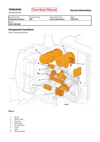
Component locations
Engine, component positions
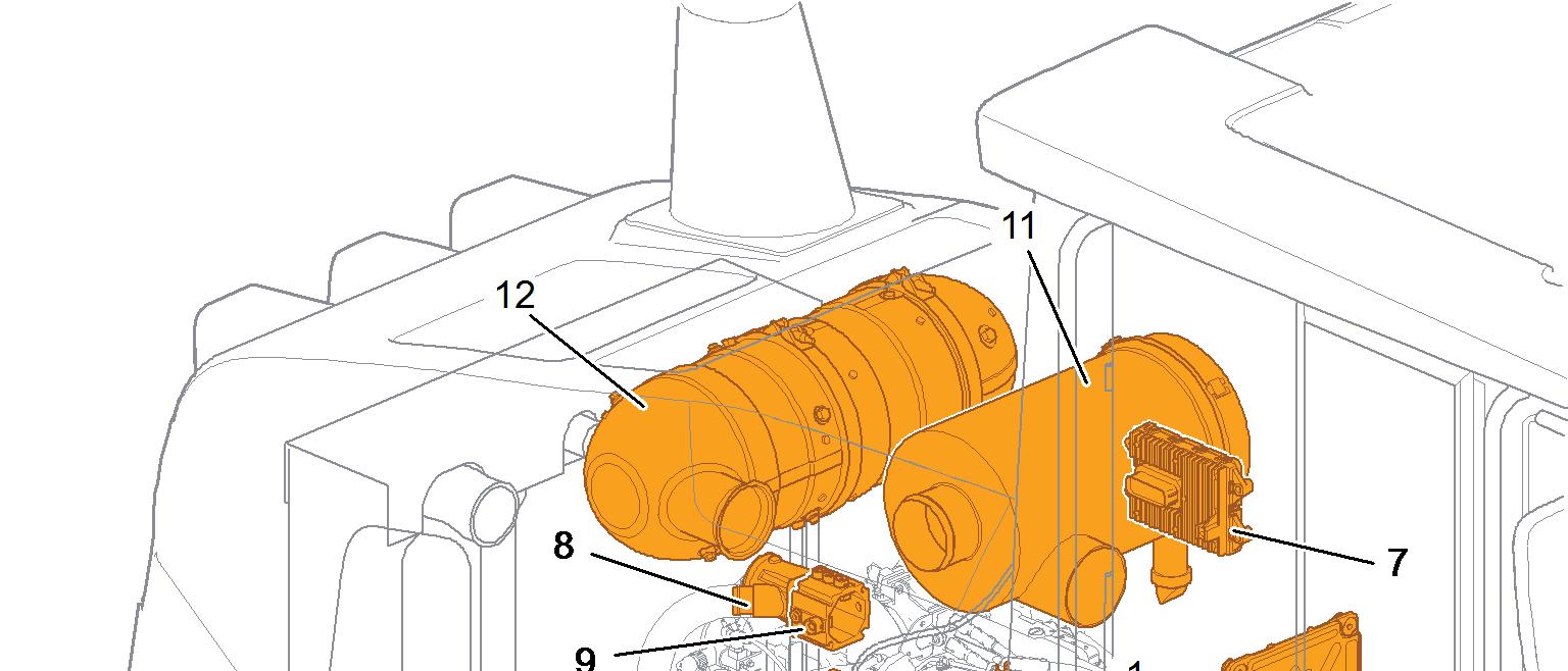

E-ECU
Figure 1
2. 3. 4.
6. 7. 8.

Electrical connections, grouping point Crankcase ventilation, separator Alternator
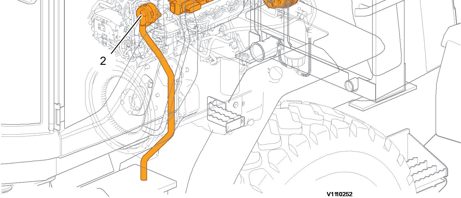
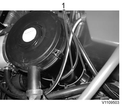
Figure 2
1. 2. 3.
Download Manual
Document Title: Function Group: Information Type: Date: VCADS Pro, Operations 200 Service Information 2014/3/21
Profile: WLO, L60G, L70G, L90G [GB]
VCADS Pro, Operations
The following VCADS Pro operations are available for function group 2. Operations used when changing or working on components are mandatory.
Tests
Operation
21006-3 Cylinder compression, test
23017-3 Feed pressure, inspection
23712-3 Injectors shut off, manual
Application
Used when there is a suspicion of fault and/or at abnormal values/readings. This test indicates if there is any deviation in compression in any cylinder in relation to the other cylinders.
As a first check this operation is both easy and fast to perform instead of a real compression test.
Used when there is a suspicion of fault and/or at abnormal values/readings.
Used when there is a suspicion of fault and/or at abnormal values/readings.
25410-3 Air pump exhaust aftertreatment, test Used when there is a suspicion of fault and/or at abnormal values/readings.
25411-3 Burner exhaust aftertreatment, test
25412-3 Components ASU, test
25457-3 Diesel Particulate Filter Service Regeneration
Used when there is a suspicion of fault and/or at abnormal values/readings.
With this sub-test, the functions of the atomiser air valve, the main air valve, the fuel shut-off valve and the fuel pump are checked.
Used when the soot load is over 1.7.
See 254 Exhaust Aftertreatment System, description
Before starting service regeneration check the differential pressure over the diesel particle filter so that it is within stated value according to the service information. This is to make sure that the DPF won’t get damaged by the service regeneration.
After the service regeneration and when the exhaust temperature has stabilized to a normal level check the differential pressure over the DPF again so that it is within stated value according to the service information. This is to determine that the filter has been regenerated correctly and that it is not clogged with ash.
26385-3 Reversible cooling fan, test
27102-3 Accelerator pedal, test
28407-3 Sensor values, monitoring
When there is a suspicion of fault and/or at abnormal values/readings.
At abnormal values/readings.
When there is a suspicion of fault and/or at abnormal values/readings.
28420-3 Flywheel and camshaft signal, test Used when there is suspicious of faulty signals or faulty connected sensor.
29332-3 Exhaust gas circulation, function test Used when there is a suspicion of fault and/or at abnormal values/readings.
Programming
Operation
Application
25801-3 MID 233 Control unit, programming When changing ACM or only reprogramming. See 254 ACM, replacing, non-programmed
28423-3 MID 128 ECU, programming
When changing ECU or only reprogramming. See 200 E-ECU, MID 128, changing non-programmed ECU
Document Title: Function Group: Information Type: Date: Engine belts, replacing 200 Service Information 2014/3/21
Profile: WLO, L60G [GB]
Engine belts, replacing
Op nbr 200-200
1. Place the machine in service position according to 191 Service position
2. Open the engine hood.
3. Remove the plastic protection (24 screws).

4. Remove the AC-belt (3 screws).
Figure 1
1. Plastic protection


Loosen the tensioning pulley and remove the belts.
5. Remove the alternator belt.
Figure 2
1. Alternator belt
Figure 3

6. Install new alternator belt and AC-belt.
7. Install the plastic protection.
8. Restore the machine.
Figure 4
AC-belt
Document Title: Function Group: Information Type: Date:
Compression test 210 Service Information 2014/3/21
Profile: WLO, L60G [GB]
Compression test
Op nbr 210-002
885812 Timing tool
9988539 Pressure gauge
88800070 Spanner
88830197 Rotation tool
88830205 Adapter
88830206 Counterhold
This operation also includes required tools and times for applicable parts of the following operations: 214 Valves, adjusting
NOTICE
Maintain greatest possible cleanliness when working on the fuel system.
1. Place the machine in service position 1, see: 191 Service position
2. Open the engine hood.
3. NOTICE Plug all pipes, hoses and connections when removing.
4. Unplug the connector and remove the hoses (2 pcs.) between the air cleaner and the turbo (3 clamps)

5. Remove the bracket for the air cleaner (2 clamps). Remove the air cleaner.
Figure 1
1. 2. Hoses Clamps
6. Remove the dust cover between the valve cover and the inlet pipe. Unplug the connector and remove the control unit (3 screws).

7. Unplug the connectors (2 pcs.) Remove the screws (2 pcs.) for the cable holder. Place the cable holder in appropriate work position.

Figure 2
1. Clamps
Figure 3
1. 2. Dust cover Connector
Figure 4
1.
8. Unplug the connectors (2 pcs.) for the injectors.

9. Remove the crankcase ventilation (2 bolts) and the valve cover (14 bolts).

10. Unplug the connectors (2 pcs.) for the FCV and the high-pressure pump.

2. Bolt Connectors
Figure 5
1. Connector
Figure 6
1. Crankcase ventilation
7
1. Connectors
11. Install 88800070 Spanner to remove the injector pipes (6 pcs.) and the rail pipes (2 pcs.) from the pump.
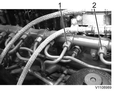
pipe
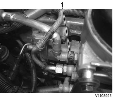
12. Remove the feed line. Attach a 10 mm (0.4 in.) hose to the feed line for circulating the fuel to the tank.

Figure
Figure 8
1. 2. Rail pipe Injector
Figure 9
1. Feed line
10
1. Hose for fuel circulating
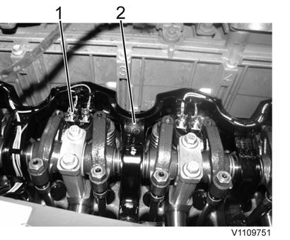
13. Remove the nut (6 pcs.) and the nozzle (6 pcs.) for the injector (6 pcs).

14. Disconnect the electric connections (12 pcs.) from the injectors and remove the screws (6 pcs.) for the bracket. Remove the cable harness (2 screws).
15. Replace the injector, use: 88830206 Counterhold.
Figure
Figure 11
1. 2. Nut Nozzle
Figure 12
1. 2. Electric connections Cable harness
13
1. 88830206 Counterhold
NOTE!
The engine must cool down for approx. 30 minutes and the oil temperature must not exceed 80 °C (176 °F).
16. Check that the valve clearances are correct, adjust as needed, see: 214 Valves, adjusting
17. Install the compression test equipment: 88830205 Adapter, 9988539 Pressure gauge. Run the engine with the starter motor for 5–10 seconds. Repeat the procedure for all the other cylinders. The difference in compression pressure should not exceed 15%.

1. 2. 88830205 Adapter 9988539 Pressure gauge
18. Remove the compression test equipment.
19. Install the injectors with new copper gaskets. Install the nut and the nozzle for the injectors. Tightening torque, attaching yoke, see: 230 Tightening torque, fuel system
20. Connect the electric connections for the injectors. Install the cable harness.
21. Install new fuel delivery lines. Tightening torque, see: 230 Tightening torque, fuel system
22. Remove the hose between the fuel feed pump and the fuel tank. Connect the fuel hose to the fuel feed pump.
23. Plug in the connectors for the FCV and the high-pressure pump.
Figure
Figure 14
24. Install the valve cover and the crankcase ventilation. Tightening torque, see: 214 Valve system, specification
25. Plug in the connectors for the injectors.
26. Install the cable holder, control unit, dust cover, and the air cleaner with clamps.
27. Plug in the connector and install the hoses between the air cleaner and the turbo.
28. Bleed the fuel system, see: 233 Fuel system, bleeding

WARNING
Make sure that high-pressure fuel cannot come into contact with unprotected parts of the body when working with injection equipment.
29. Restore the machine.
Document Title: Function Group: Information Type: Date: Engine rotation speed sensor (crank shaft), replacing 210 Service Information 2014/3/21
Profile: WLO, L60G [GB]
Engine rotation speed sensor (crank shaft), replacing
Op nbr 210-093
1. Place the machine in service position according to . 191 Service position
2. Open the engine hood.
3. Unplug the connector and loosen the screw that holds the speed sensor.


Figure 1
1. Connector
4. Remove the speed sensor.
Figure 2
1. 2. Loose speed sensor O-ring
5. Replace the O-ring.
6. Install a new speed sensor and plug in the connector.
7. Restore the machine.
Document Title: Function Group: Information Type: Date: Engine rotation speed sensor (camshaft), replacing 210 Service Information 2014/3/21
Profile: WLO, L60G [GB]
Engine rotation speed sensor (camshaft), replacing
Op nbr 210-092
1. Place the machine in service position according to . 191 Service position
2. Open the engine hood.
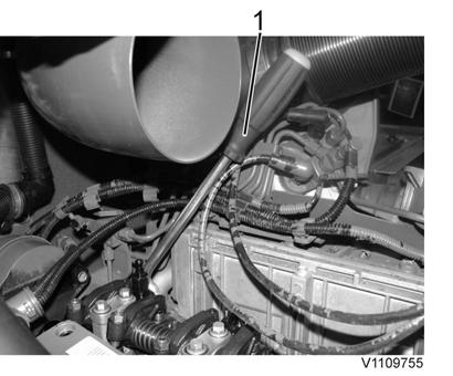
3. Remove the oil pipe (2 screws).

4. Cut the cable tie, unplug the connector and loosen the screw that holds the speed sensor.
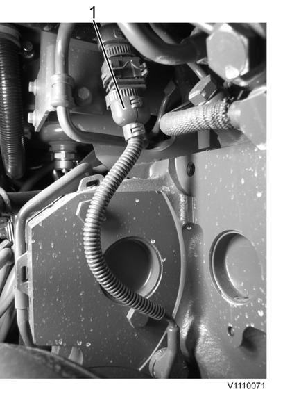
Figure 1
1. Oil pipe
5. Remove the speed sensor.

6. Replace the O-ring.
7. Install a new speed sensor and plug in the connector.
8. Install the oil pipe. Tightening torques:
M12 (banjo screw): 20 ±3 Nm (14.8 ±2.2 lbf ft)
M16 (banjo screw): 40 ±5 Nm (29.5 ±3.7 lbf ft)
9. Restore the machine.
DOWNLOAD MANUAL
Figure 3
2. Connector Speed sensor