Technical Information Feedback Form
We need your help to continually improve our technical publications. Please copy this page and FAX or mail your comments, ideas and improvements.
SEND TO: John Deere Dubuque Works
P.O. Box 538
Attn: Publications Supervisor, Dept. 303 Dubuque, IA 52004-0538
FAX NUMBER: 563-589-5800
Ideas, Comments (Please State Page Number):
OVERALL, how would you rate the quality of this publication? (Check one)
Acct. No.: THANK YOU!
(28NOV01)
101603 PN=3
Introduction TM1663
200LC Excavator Operation & Tests
Poor Fair Good Very Good Excellent 1 2 3 4 5 6 7 8 9 10 Company
Technician
Address: Phone: Fax
Dealer
TX,TM,FAX –19–28NOV01–1/1
Name:
Name:
No.:
Introduction
TM1663 (28NOV01)
101603 PN=4
200LC Excavator Operation & Tests
SECTION 9000—General Information
Group 01 Safety
Group 02 General Specifications
Group 03 Torque Values
Group 04 Fuels and Lubricants
SECTION 9005 Operational Checkout Procedure
Group 10 Operational Checkout Procedure
SECTION 9010—Engine Group 05 Theory of Operation
Group 10 System Operational Checks
Group 15 Diagnostic Information
Group 20 Adjustments
Group 25 Tests
SECTION 9015 Electrical System
Group 05 System Information
Group 10 System Diagrams
Group 15 Sub-System Diagnostics Group 20 References
SECTION 9020—Power Train Group 05 Theory of Operation
Group 15 Diagnostic Information Group 20 Adjustments
SECTION 9025 Hydraulic System
Group 05 Theory of Operation
Group 15 Diagnostic Information
Group 20 Adjustment
Group 25 Tests
SECTION 9031 Air Conditioning System
Group 05 Theory of Operation
Group 10 System Operational Checks
Group 15 Diagnostic Information
Group 20 Adjustments
Group 25 Tests
All information, illustrations and specifications in this manual are based on the latest information available at the time of publication. The right is reserved to make changes at any time without notice.
i TM1663
200LC Excavator Operation & Tests 101603 PN=1
(28NOV01)
COPYRIGHT © 2002 DEERE & COMPANY Moline, Illinois All rights reserved A John Deere ILLUSTRUCTION Manual Previous Editions Copyright © 2000, 1998, 1996 9000 9005 9010 9015 9020 9025 9031 INDX Contents
ii TM1663 (28NOV01) 200LC Excavator Operation & Tests 101603 PN=2 9000 9005 9010 9015 9020 9025 9031 INDX Contents
9000-1
(28NOV01) 200LC Excavator Operation & Tests 101603 PN=1 Section 9000 General Information Contents 9000 Page Page Group 01—Safety.......................................... 9000-01-1 Group 02—General Specifications Excavator Overview 9000-02-1 200LC Specifications 9000-02-2 200LC Working Ranges 9000-02-4 200LC Engine Specifications 9000-02-6 200LC Drain and Refill Capacities 9000-02-6 Track Adjuster, Working Tool Pivot, Swing Bearing, and Swing Bearing Gear Grease 9000-04-7 Oil Filters 9000-04-7 Lubricant Storage 9000-04-8 Alternative and Synthetic Lubricants 9000-04-8 Mixing of Lubricants........................................9000-04-9 Group 03 Torque Values Unified Inch Bolt and Cap Screw Torque Values 9000-03-1 Metric Bolt and Cap Screw Torque Values 9000-03-2 Additional Metric Cap Screw Torque Values 9000-03-3 Check Oil Lines And Fittings .......................... 9000-03-5 Service Recommendations for O-Ring Boss Fittings 9000-03-6 Service Recommendations For Flat Face O-Ring Seal Fittings 9000-03-8 Service Recommendations for 37 Flare and 30 Cone Seat Connectors 9000-03-9 Service Recommendations For Flared Connections Straight or Tapered Threads 9000-03-10 Service Recommendations For Inch Series Four Bolt Flange Fittings 9000-03-11 Service Recommendations for Metric Series Four Bolt Flange Fitting 9000-03-12 Group 04 Fuels and Lubricants Diesel Fuel 9000-04-1 Lubricity of Diesel Fuels 9000-04-1 Low Sulfur Diesel Fuel Conditioner 9000-04-2 Diesel Fuel Storage 9000-04-2 Fuel Tank........................................................9000-04-3 Do Not Use Galvanized Containers 9000-04-3 Diesel Engine Oil 9000-04-4 Hydraulic Oil 9000-04-5 Swing Gearbox, Propel Gearbox and Pump Gearbox Oils ...............................................9000-04-6 Track Roller, Front Idler, and Carrier Roller Oil 9000-04-6
TM1663
9000-2 TM1663 (28NOV01) 200LC Excavator Operation & Tests 101603 PN=2 9000 Contents
Follow Safe Procedures
Unsafe work practices are dangerous. Understand service procedure before doing work; do not attempt shortcuts.

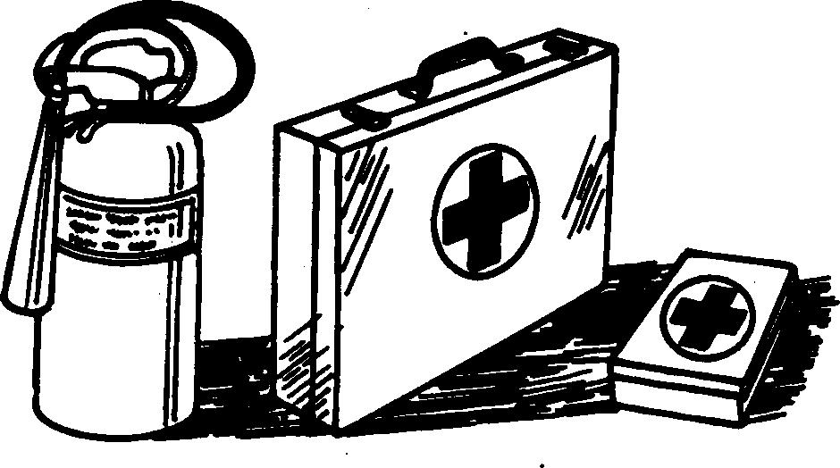
Prepare for Emergencies
Be prepared if a fire starts.
Keep a first aid kit and fire extinguisher handy. Keep emergency numbers for doctors, ambulance service, hospital, and fire department near your telephone.
Handle Fluids Safely Avoid Fires
Handle fuel with care; it is highly flammable. Do not refuel the machine while smoking or when near open flame or sparks. Always stop engine before refueling machine. Fill fuel tank outdoors.
Store flammable fluids away from fire hazards. Do not incinerate or puncture pressurized containers.

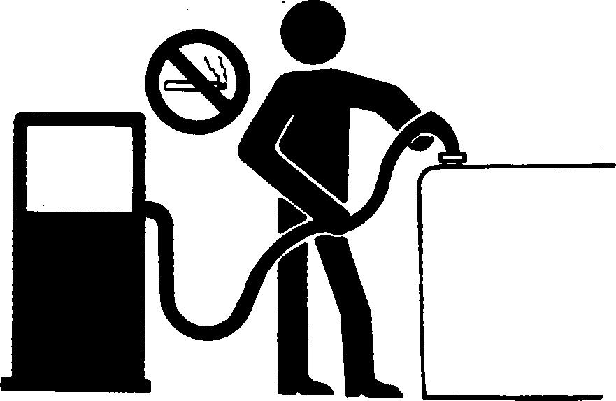
Make sure machine is clean of trash, grease, and debris.
Do not store oily rags; they can ignite and burn spontaneously.
101603 PN=9 TS231 –19 –07OCT88
9000 01 1
TX,05,FF1611 –19–14JUN90–1/1 TM1663 (28NOV01) 9000-01-1 200LC Excavator Operation & Tests
01 Safety
Group
DX,FIRE2 –19–03MAR93–1/1
TX,05,FF1622 –19–14JUN90–1/2
TX,05,FF1622 –19–14JUN90–2/2 TS227 –UN –23AUG88 TS202 –UN –23AUG88 TS291 –UN –23AUG88
Prevent Battery Explosions
Keep sparks, lighted matches, and open flame away from the top of battery. Battery gas can explode.
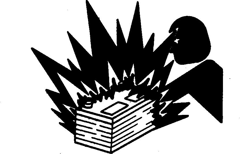
Never check battery charge by placing a metal object across the posts. Use a volt-meter or hydrometer.
Do not charge a frozen battery; it may explode. Warm battery to 16C (60F).
Handle Chemical Products Safely
Direct exposure to hazardous chemicals can cause serious injury. Potentially hazardous chemicals used with John Deere equipment include such items as lubricants, coolants, paints, and adhesives.
A Material Safety Data Sheet (MSDS) provides specific details on chemical products: physical and health hazards, safety procedures, and emergency response techniques.
Check the MSDS before you start any job using a hazardous chemical. That way you will know exactly what the risks are and how to do the job safely. Then follow procedures and recommended equipment.
(See your John Deere dealer for MSDS’s on chemical products used with John Deere equipment.)

Safety
TM1663 (28NOV01) 200LC Excavator Operation & Tests 101603 PN=10 9000 01 2
9000-01-2
DX,SPARKS –19–03MAR93–1/1
DX,MSDS,NA –19–03MAR93–1/1 TS1132 –UN –26NOV90 TS204 –UN –23AUG88
Prevent Acid Burns
Sulfuric acid in battery electrolyte is poisonous. It is strong enough to burn skin, eat holes in clothing, and cause blindness if splashed into eyes.
Avoid the hazard by:
1. Filling batteries in a well-ventilated area.
2. Wearing eye protection and rubber gloves.
3. Avoiding breathing fumes when electrolyte is added.
4. Avoiding spilling or dripping electrolyte.
5. Use proper jump start procedure.

If you spill acid on yourself:
1. Flush your skin with water.
2. Apply baking soda or lime to help neutralize the acid.
3. Flush your eyes with water for 15 30 minutes. Get medical attention immediately.
If acid is swallowed:
1. Do not induce vomiting.
2. Drink large amounts of water or milk, but do not exceed 2 L (2 quarts).
3. Get medical attention immediately.
Safety
101603 PN=11 TS203 –UN –23AUG88
9000-01-3 TM1663 (28NOV01) 200LC Excavator Operation & Tests
9000 01 3
DX,POISON –19–21APR93–1/1
Avoid High-Pressure Fluids
Escaping fluid under pressure can penetrate the skin causing serious injury.
Avoid the hazard by relieving pressure before disconnecting hydraulic or other lines. Tighten all connections before applying pressure.
Search for leaks with a piece of cardboard. Protect hands and body from high pressure fluids.
If an accident occurs, see a doctor immediately. Any fluid injected into the skin must be surgically removed within a few hours or gangrene may result. Doctors unfamiliar with this type of injury should reference a knowledgeable medical source. Such information is available from Deere & Company Medical Department in Moline, Illinois, U.S.A.
Warn Others of Service Work
Unexpected machine movement can cause serious injury.
Before performing any work on the machine, attach a “Do Not Operate” tag on the right control lever.


Safety
200LC
101603 PN=12 9000 01 4
9000-01-4 TM1663 (28NOV01)
Excavator Operation & Tests
DX,FLUID –19–03MAR93–1/1
TX,05,RR,566 –19–23JUL91–1/1 X9811 –UN –23AUG88 T7273AP –UN –08JUN90
Park Machine Safely
Before working on the machine:
• Park machine on a level surface.
• Lower bucket to the ground.
• Turn auto-idle switch off.
• Run engine with engine RPM dial at 1/3 position for 2 minutes.
• Move engine RPM dial to slow idle position.
• Turn key switch to OFF. Remove key from switch.
• Pull pilot control shut-off lever to locked position.
• Allow engine to cool.
Support Machine Properly
Always lower the attachment or implement to the ground before you work on the machine. If the work requires that the machine or attachment be lifted, provide secure support for them. If left in a raised position, hydraulically supported devices can settle or leak down.
Do not support the machine on cinder blocks, hollow tiles, or props that may crumble under continuous load. Do not work under a machine that is supported solely by a jack. Follow recommended procedures in this manual.

When implements or attachments are used with a machine, always follow safety precautions listed in the implement or attachment operator’s manual.

Operate Only from Operator’s Seat
Avoid possible injury or machine damage. Do not start engine by shorting across starter terminals.
NEVER start engine while standing on ground. Start engine only from operator’s seat.
Safety
9000-01-5
TM1663 (28NOV01)
101603 PN=13
200LC Excavator Operation & Tests
9000 01 5
TX,05,DH5002 –19–28MAY96–1/1
DX,LOWER –19–24FEB00–1/1
TX,05,FF1615 –19–14JUN90–1/1 T6607AO –UN –18OCT88 TS229 –UN –23AUG88
Stay Clear of Moving Parts

Entanglements in moving parts can cause serious injury.
To prevent accidents, use care when working around rotating parts.
Avoid Power Lines
Serious injury or death can result from contact with electric lines.

Never move any part of the machine or load closer to electric line than 3 m (10 ft) plus twice the line insulator length.
Use Handholds and Steps
Falling is one of the major causes of personal injury.

When you get on and off the machine, always maintain a three point contact with the steps and handrails and face the machine. Do not use any controls as handholds.
Never jump on or off the machine. Never mount or dismount a moving machine.
Be careful of slippery conditions on platforms, steps, and handrails when leaving the machine.
Safety
200LC Excavator Operation & Tests 101603 PN=14 9000 01 6
9000-01-6 TM1663 (28NOV01)
TX,05,RR,572 –19–12JUN90–1/1
TX,05,RR,594 –19–12JUN90–1/1
TX,05,DH832 –19–16MAR92–1/1 T6981AN –UN –15JUN89 T7273AD –UN –08JUN90 T7273AS –UN –08JUN90
Keep Riders Off Machine
Only allow the operator on the machine. Keep riders off.
Riders on machine are subject to injury such as being struck by foreign objects and being thrown off the machine. Riders also obstruct the operator’s view resulting in the machine being operated in an unsafe manner.
Move and Operate Machine Safely


Bystanders can be run over. Know the location of bystanders before moving, swinging, or operating the machine.
Always keep the travel alarm in working condition. It warns people when the machine starts to move.
Use a signal person when moving, swinging, or operating the machine in congested areas. Coordinate hand signals before starting the machine.
Wear Protective Clothing
Wear close fitting clothing and safety equipment appropriate to the job.
Operating equipment safely requires the full attention of the operator. Do not wear radio or music headphones while operating machine.

Safety
9000-01-7
101603 PN=15 T7273AH –UN –08JUN90
TM1663 (28NOV01) 200LC Excavator Operation & Tests
9000 01 7
TX,05,RR,560 –19–05OCT90–1/1
TX,05,FF1806 –19–05OCT90–1/1
DX,WEAR2 –19–03MAR93–1/1 TS206 –UN –23AUG88 T7273AL –UN –08JUN90
Protect Against Flying Debris
Guard against injury from flying pieces of metal or debris; wear goggles or safety glasses.


Protect Against Noise
Prolonged exposure to loud noise can cause impairment or loss of hearing.

Wear a suitable hearing protective device such as earmuffs or earplugs to protect against objectionable or uncomfortable loud noises.
Illuminate Work Area Safely
Illuminate your work area adequately but safely. Use a portable safety light for working inside or under the machine. Make sure the bulb is enclosed by a wire cage. The hot filament of an accidentally broken bulb can ignite spilled fuel or oil.
Service Machines Safely
Tie long hair behind your head. Do not wear a necktie, scarf, loose clothing, or necklace when you work near machine tools or moving parts. If these items were to get caught, severe injury could result.
Remove rings and other jewelry to prevent electrical shorts and entanglement in moving parts.
9000-01-8
Safety
TM1663 (28NOV01)
101603 PN=16 9000 01 8
200LC Excavator Operation & Tests
TX,05,FF1613 –19–14JUN90–1/1
DX,NOISE –19–03MAR93–1/1
DX,LIGHT –19–04JUN90–1/1
DX,LOOSE –19–04JUN90–1/1 TS228 –UN –23AUG88 TS223 –UN –23AUG88 TS207 –UN –23AUG88 T6642DK –UN –18OCT88
Remove Paint Before Welding or Heating
Avoid potentially toxic fumes and dust.
Hazardous fumes can be generated when paint is heated by welding, soldering, or using a torch. Remove paint before heating:
• Remove paint a minimum of 76 mm (3 in.) from area to be affected by heating.
• If you sand or grind paint, avoid breathing the dust. Wear an approved respirator.

• If you use solvent or paint stripper, remove stripper with soap and water before welding. Remove solvent or paint stripper containers and other flammable material from area. Allow fumes to disperse at least 15 minutes before welding or heating.
Do all work in an area that is ventilated to carry toxic fumes and dust away.
Dispose of paint and solvent properly.
Avoid Heating Near Pressurized Fluid Lines
Flammable spray can be generated by heating near pressurized fluid lines, resulting in severe burns to yourself and bystanders. Do not heat by welding, soldering, or using a torch near pressurized fluid lines or other flammable materials. Pressurized lines can be accidentally cut when heat goes beyond the immediate flame area.

Beware of Exhaust Fumes
Prevent asphyxiation. Engine exhaust fumes can cause sickness or death.
If you must operate in a building, be positive there is adequate ventilation. Either use an exhaust pipe extension to remove the exhaust fumes or open doors and windows to bring enough outside air into the area.

Safety
200LC
& Tests 101603 PN=17 TS220 –UN –23AUG88
9000-01-9 TM1663 (28NOV01)
Excavator Operation
9000 01 9
DX,PAINT –19–22OCT99–1/1
DX,TORCH –19–03MAR93–1/1
02T,05,J9 –19–07JAN91–1/1 T6458AO –UN –18OCT88 TS953 –UN –15MAY90
Use Proper Lifting Equipment
Lifting heavy components incorrectly can cause severe injury or machine damage.

Follow recommended procedure for removal and installation of components in the manual.
Service Cooling System Safely
Explosive release of fluids from pressurized cooling system can cause serious burns.

Shut off engine. Only remove filler cap when cool enough to touch with bare hands. Slowly loosen cap to first stop to relieve pressure before removing completely.
Dispose of Waste Properly
Improperly disposing of waste can threaten the environment and ecology. Potentially harmful waste used with John Deere equipment include such items as oil, fuel, coolant, brake fluid, filters, and batteries.
Use leakproof containers when draining fluids. Do not use food or beverage containers that may mislead someone into drinking from them.
Do not pour waste onto the ground, down a drain, or into any water source.
Air conditioning refrigerants escaping into the air can damage the Earth’s atmosphere. Government regulations may require a certified air conditioning service center to recover and recycle used air conditioning refrigerants.
Inquire on the proper way to recycle or dispose of waste from your local environmental or recycling center, or from your John Deere dealer.

Safety
101603 PN=18 9000 01 10
9000-01-10 TM1663 (28NOV01) 200LC Excavator Operation & Tests
DX,LIFT –19–04JUN90–1/1
DX,RCAP –19–04JUN90–1/1
DX,DRAIN –19–03MAR93–1/1 TS1133 –UN –26NOV90 TS281 –UN –23AUG88 TS226 –UN –23AUG88
Work in a Clean Area
Before starting a job, clean the work area. Remove objects that may be a safety hazard to the mechanic or bystanders.
Use Tools Properly
Use tools appropriate to the work. Makeshift tools, parts, and procedures can create safety hazards.
Use power tools only to loosen threaded tools and fasteners.
For loosening and tightening hardware, use the correct size tools. DO NOT use U.S. measurement tools on metric fasteners. Avoid bodily injury caused by slipping wrenches.

Use only recommended replacement parts. (See Parts Catalog.)
Replace Safety Signs
Replace missing or damaged safety signs. See the machine operator’s manual for correct safety sign placement.

Safety 9000-01-11 TM1663 (28NOV01) 200LC Excavator Operation & Tests 101603 PN=19
9000 01 11
TX,05,FF1624 –19–14JUN90–1/1
TX,05,FF1614 –19–14JUN90–1/1
DX,SIGNS1 –19–04JUN90–1/1 TS201 –UN –23AUG88 TS779 –UN –08NOV89
Live With Safety
Before returning machine to customer, make sure machine is functioning properly, especially the safety systems. Install all guards and shields.
Safety 9000-01-12
200LC
101603 PN=20 9000 01 12
TM1663 (28NOV01)
Excavator Operation & Tests
DX,LIVE –19–25SEP92–1/1 TS231 –19 –07OCT88

101603 PN=21 Excavator Overview 9000 02 1 CED,TX08227,2993 –19–10FEB98–1/1 TM1663 (28NOV01) 9000-02-1 200LC Excavator Operation & Tests Group 02 General Specifications T115683 –UN –02JUN98
NOTE: Specifications and design subject to change without notice. Wherever applicable, specifications are in accordance with PCSA and SAE standards. Except where otherwise noted these specifications are based on a
machine equipped with 800 mm (32 in.) shoes, counterweight, 2.91 m (9 ft 7 in.) arm, 723 kg (1590 lb) 0.86 m 3 (1.12 yd 3) bucket, full fuel tank, 79 kg (175 lb) operator and standard equipment.

200LC Excavator Operation & Tests 101603 PN=22 9000 02 2 200LC Specifications A Sprocket Center To Idler D Rear End Swing Radius H Center Of Sprocket To J Undercarriage Width Center E Overall Width Center Of Sprocket K Overall Length B Undercarriage Length F Cab Height I Track Shoe Width L Transport Height C Counterweight Clearance G Minimum Ground Clearance
General Specifications 9000-02-2 TM1663 (28NOV01)
Item Measurement Specification A Sprocket Center To Idler Center Distance 3660 mm (12 ft 0 in.) B Undercarriage Length 4460 mm (14 ft 8 in.)
Counterweight Clearance Distance 1030 mm (3 ft 5 in.)
Rear End Swing Radius Distance 2720 mm (8 ft 11 in.)
Overall Width
Distance 2720 mm (8 ft 11 in.)
Cab Height 2720 mm (8 ft 11 in.) Continued on next page CED,TX14740,6954 –19–07SEP00–1/2 T113215 –UN –03FEB98
C
D
E
(Excluding Back
Mirrors) F
General Specifications
G Minimum Ground Clearance Distance 450 mm (1 ft 6 in.)
H Center Of Sprocket To Center Of Sprocket Distance 2390 mm (7 ft 10 in.)
I Track Shoe Width 600 mm (24 in.) or 700 mm (28 in.) or 800 mm (32 in.)
J Undercarriage Width Width Width
K Machine Overall Length Overall Length
L Machine Transport Height Transport Height
With 600 mm (24 in.) shoes: 2990 mm (9 ft 10 in.)
With 700 mm (28 in.) shoes: 3090 mm (10 ft 2 in.)
With 800 mm (32 in.) shoes: 3190 mm (10 ft 6 in.)
With 2220 mm (7 ft 3 in.) Arm: 9620 mm (31 ft 7 in.)
With 2910 mm (9 ft 7 in.) Arm: 9500 mm (31 ft 2 in.)
With 2220 mm (7 ft 3 in.) Arm: 3090 mm (10 ft 2 in.)
With 2910 mm (9 ft 7 in.) Arm: 2970 mm (9 ft 9 in.)
TM1663 (28NOV01)
9000-02-3
200LC Excavator Operation & Tests
101603 PN=23 Item Measurement Specification 9000 02 3
Machine Operating Weight 20 298 kg (44,750 lb) CED,TX14740,6954 –19–07SEP00–2/2

Specifications 9000-02-4 TM1663 (28NOV01) 200LC Excavator Operation & Tests 101603 PN=24 9000 02 4 200LC
A Maximum Digging Reach B Maximum Digging Depth E Maximum Cutting Height G Minimum Swing Radius A1 Maximum Digging Reach C Maximum Vertical Wall F Maximum Dumping Height At Ground Level D—Maximum Digging Depth (Flat Bottom) Item Measurement Specification A Maximum Digging Reach Distance With 2220 mm (7 ft 3 in.) Arm: 9250 mm (30 ft 4 in.) Distance With 2910 mm (9 ft 7 in.) Arm: 9910 mm (32 ft 6 in.) Continued on next page TX,115,DH5117 –19–15JUL96–1/2 T102389 –UN –24MAR97
General
Working Ranges
101603 PN=25 Item Measurement Specification 9000 02 5 A1 Maximum Digging Reach At Ground Level Distance Distance With 2220 mm (29 ft With 2910 mm (32 ft mm (7 ft 3 in.) 9 in.) mm (9 ft 7 in.) 0 in.) Arm: 9080 Arm: 9750 B Maximum Digging Depth Depth Depth With 2220 mm (19 ft With 2910 mm (21 ft mm (7 ft 3 in.) 7 in.) mm (9 ft 7 in.) 11 in.) Arm: 5980 Arm: 6670 C Maximum Vertical Wall Depth Depth With 2220 mm (16 ft With 2910 mm (19 ft mm (7 ft 3 in.) 10 in.) mm (9 ft 7 in.) 10 in.) Arm: 5140 Arm: 6050 D Maximum Digging Depth (Flat Bottom) Depth Depth With 2220 mm (18 ft With 2910 mm (21 ft mm (7 ft 3 in.) 10 in.) mm (9 ft 7 in.) 4 in.) Arm: 5740 Arm: 6490 E Maximum Cutting Height Height Height With 2220 mm (30 ft With 2910 mm (31 ft mm (7 ft 3 in.) 1 in.) mm (9 ft 7 in.) 6 in.) Arm: 9170 Arm: 9600 F Maximum Dumping Height Height Height With 2220 mm (21 ft With 2910 mm (22 ft mm (7 ft 3 in.) 0 in.) mm (9 ft 7 in.) 3 in.) Arm: 6390 Arm: 6780 G Minimum Swing Radius Radius Radius With 2220 mm (11 ft With 2910 mm (11 ft mm (7 ft 3 in.) 7 in.) mm (9 ft 7 in.) 7 in.) Arm: 3540 Arm: 3540 TX,115,DH5117 –19–15JUL96–2/2
General Specifications 9000-02-5 TM1663 (28NOV01) 200LC Excavator Operation & Tests
200LC Engine Specifications
200LC Drain and Refill Capacities
Specifications 9000-02-6
200LC Excavator Operation & Tests 101603 PN=26
General
TM1663 (28NOV01)
Item Measurement Specification Fuel Tank Capacity 303 L (80 gal) Cooling System Capacity 28.4 L (7.5 gal) Engine Oil Capacity, Including Filter Change 19 L (5.0 gal) Hydraulic System Capacity 250 L (66 gal) Hydraulic Tank Capacity 130 L (34 gal) Swing Gearbox Capacity 4.7 L (5.0 qt) Propel Gearbox (Each) Capacity 5.2 L (5.5 qt) Pump Drive Gearbox Capacity 1.0 L (1.1 qt) TX,115,DH5114 –19–15JUL96–1/1
Item Measurement Specification John Deere POWERTECH 6.8 Type Bore And Stroke Cylinders Displacement Net Torque @ 1300 RPM Compression Ratio Power At 2150 RPM Lubrication Cooling Fan Electrical system Batteries (2) 12 volt
Cycle, Turbocharged, Aftercooled
x 127 mm (4.17 x 5.0 in.) 6 6.785 L (414 cu in.)
N•m (427 lb-ft) 17:1
kW
Net SAE Pressure System
Filter Suction 24 Volt 180 Minutes Reserve Capacity: POWERTECH is a trademark of Deere & Company. CED,TX14740,6956 –19–07SEP00–1/1 9000 02 6
4-Stroke
106
579
104
(140 hp)
With Full-Flow
Unified Inch Bolt and Cap Screw Torque Values
a Grade 2 applies for hex cap screws (not hex bolts) up to 6 in. (152 mm) long. Grade 1 applies for hex cap screws over 6 in. (152 mm) long, and for all other types of bolts and screws of any length.
b "Lubricated" means coated with a lubricant such as engine oil, or fasteners with phosphate and oil coatings.
c "Dry" means plain or zinc plated without any lubrication.
DO NOT use these values if a different torque value or tightening Make sure fastener threads are clean and that you properly start procedure is given for a specific application. Torque values listed are thread engagement. This will prevent them from failing when for general use only. Check tightness of fasteners periodically. tightening.
Shear bolts are designed to fail under predetermined loads. Always Tighten plastic insert or crimped steel-type lock nuts to approximately replace shear bolts with identical grade. 50 percent of the dry torque shown in the chart, applied to the nut, not to the bolt head. Tighten toothed or serrated-type lock nuts to the full torque value.
Fasteners should be replaced with the same or higher grade. If higher grade fasteners are used, these should only be tightened to the strength of the original.

101603 PN=27
9000 03 1 Top, SAE Grade and Head Markings; Bottom, SAE Grade and Nut Markings Grade 1 (No Mark) Grade 2a (No Mark) Grade 5, 5.1 or 5.2 Grade 8 or 8.2 Size Lubricatedb N•m(lb-ft) Dryc N•m(lb-ft) Lubricatedb N•m(lb-ft) Dryc N•m(lb-ft) Lubricatedb N•m(lb-ft) Dryc N•m(lb-ft) Lubricatedb N•m(lb-ft) Dryc N•m(lb-ft) 1/4 3.8 (2.8) 4.7 (3.5) 6 (4.4) 7.5 (5.5) 9.5 (7) 12 (9) 13.5 (10) 17 (12.5) 5/16 7.7 (5.7) 9.8 (7.2) 12 (9) 15.5 (11.5) 19.5 (14.5) 25 (18.5) 28 (20.5) 35 (26) 3/8 13.5 (10) 17.5 (13) 22 (16) 27.5 (20) 35 (26) 44 (32.5) 49 (36) 63 (46) 7/16 22 (16) 28 (20.5) 35 (26) 44 (32.5) 56 (41) 70 (52) 80 (59) 100 (74) 1/2 34 (25) 42 (31) 53 (39) 67 (49) 85 (63) 110 (80) 120 (88) 155 (115) 9/16 48 (35.5) 60 (45) 76 (56) 95 (70) 125 (92) 155 (115) 175 (130) 220 (165) 5/8 67 (49) 85 (63) 105 (77) 135 (100) 170 (125) 215 (160) 240 (175) 305 (225) 3/4 120 (88) 150 (110) 190 (140) 240 (175) 300 (220) 380 (280) 425 (315) 540 (400) 7/8 190 (140) 240 (175) 190 (140) 240 (175) 490 (360) 615 (455) 690 (510) 870 (640) 1 285 (210) 360 (265) 285 (210) 360 (265) 730 (540) 920 (680) 1030 (760) 1300 (960) 1-1/8 400 (300) 510 (375) 400 (300) 510 (375) 910 (670) 1150 (850) 1450 (1075) 1850 (1350) 1-1/4 570 (420) 725 (535) 570 (420) 725 (535) 1280 (945) 1630 (1200) 2050 (1500) 2600 (1920) 1-3/8 750 (550) 950 (700) 750 (550) 950 (700) 1700 (1250) 2140 (1580) 2700 (2000) 3400 (2500) 1-1/2 990 (730) 1250 (930) 990 (730) 1250 (930) 2250 (1650) 2850 (2100) 3600 (2650) 4550 (3350)
DX,TORQ1 –19–01OCT99–1/1 TM1663 (28NOV01) 9000-03-1 200LC Excavator Operation & Tests
TORQ1A –UN –27SEP99
Group 03 Torque Values
Metric Bolt and Cap Screw Torque Values
a "Lubricated" means coated with a lubricant such as engine oil, or fasteners with phosphate and oil coatings. b "Dry" means plain or zinc plated without any lubrication.
DO NOT use these values if a different torque value or tightening
Make sure fastener threads are clean and that you properly start procedure is given for a specific application. Torque values listed are thread engagement. This will prevent them from failing when for general use only. Check tightness of fasteners periodically. tightening.
Shear bolts are designed to fail under predetermined loads. Always Tighten plastic insert or crimped steel-type lock nuts to approximately replace shear bolts with identical property class. 50 percent of the dry torque shown in the chart, applied to the nut, not to the bolt head. Tighten toothed or serrated-type lock nuts to the full torque value.

Fasteners should be replaced with the same or higher property class. If higher property class fasteners are used, these should only be tightened to the strength of the original.
9000-03-2
Torque Values
101603 PN=28 9000 03 2
TM1663 (28NOV01) 200LC Excavator Operation & Tests
Top, Property Class and Head Markings; Bottom, Property Class and Nut Markings Class 4.8 Class 8.8 or 9.8 Class 10.9 Class 12.9 Size Lubricateda N•m(lb-ft) Dryb N•m(lb-ft) Lubricateda N•m(lb-ft) Dryb N•m(lb-ft) Lubricateda N•m(lb-ft) Dryb N•m(lb-ft) Lubricateda N•m(lb-ft) Dryb N•m(lb-ft) M6 4.7 (3.5) 6 (4.4) 9 (6.6) 11.5 (8.5) 13 (9.5) 16.5 (12.2) 15.5 (11.5) 19.5 (14.5) M8 11.5 (8.5) 14.5 (10.7) 22 (16) 28 (20.5) 32 (23.5) 40 (29.5) 37 (27.5) 47 (35) M10 23 (17) 29 (21) 43 (32) 55 (40) 63 (46) 80 (59) 75 (55) 95 (70) M12 40 (29.5) 50 (37) 75 (55) 95 (70) 110 (80) 140 (105) 130 (95) 165 (120) M14 63 (46) 80 (59) 120 (88) 150 (110) 175 (130) 220 (165) 205 (150) 260 (190) M16 100 (74) 125 (92) 190 (140) 240 (175) 275 (200) 350 (255) 320 (235) 400 (300) M18 135 (100) 170 (125) 265 (195) 330 (245) 375 (275) 475 (350) 440 (325) 560 (410) M20 190 (140) 245 (180) 375 (275) 475 (350) 530 (390) 675 (500) 625 (460) 790 (580) M22 265 (195) 330 (245) 510 (375) 650 (480) 725 (535) 920 (680) 850 (625) 1080 (800) M24 330 (245) 425 (315) 650 (480) 820 (600) 920 (680) 1150 (850) 1080 (800) 1350 (1000) M27 490 (360) 625 (460) 950 (700) 1200 (885) 1350 (1000) 1700 (1250) 1580 (1160) 2000 (1475) M30 660 (490) 850 (625) 1290 (950) 1630 (1200) 1850 (1350) 2300 (1700) 2140 (1580) 2700 (2000) M33 900 (665) 1150 (850) 1750 (1300) 2200 (1625) 2500 (1850) 3150 (2325) 2900 (2150) 3700 (2730) M36 1150 (850) 1450 (1075) 2250 (1650) 2850 (2100) 3200 (2350) 4050 (3000) 3750 (2770) 4750 (3500)
DX,TORQ2 –19–01OCT99–1/1 TORQ2 –UN –07SEP99