DF Series 150 and 250 Transmissions (ANALOG)

Funk Manufacturing Company CTM147 (16JUL98) LITHO IN U.S.A. ENGLISH
DF Series 150 and 250 Transmissions (Analog)
CTM147 (16JUL98)
FOREWORD
Component Technical Manuals (CTM) are concise service guides for specific components. Component technical manuals are written as stand-alone manuals covering multiple machine applications.
This manual is written for an experienced technician. Essential tools required in performing certain service work are identified in this manual and are recommended for use.
Live with safety: Read the safety messages in the introduction of this manual and the cautions presented throughout the text of the manual.
NThis is the safety-alert symbol. When you see this symbol in the manual or on the machine, be alert to the potential for personal injury.
NWARNING VEHICLE RUNAWAY HAZARD
Avoid serious or fatal injury. This transmission is not a braking system. Install it only if there is a braking system capable of stopping vehicle with dead engine, disengaged transmission, or loss of hydrostatic retardation. Otherwise, vehicle may roll freely, resulting in loss of control.
IMPORTANT: Important warns of possible damage to transmission.
NOTE: To make special mention of or to record in writing useful information about the transmission.
Use this component technical manual in conjunction with the machine technical manual. See the machine technical manual for information on component removal and installation, and gaining access to the components.
This manual is divided in three parts; general information, repair, and troubleshooting and tests:
• General information group offers component identification with specification information about the transmission.
• Repair groups contain necessary instructions to repair the component.
• Troubleshooting and test groups help you identify the majority of routine failures quickly and then allows you to perform certain tests.
Information is organized in groups for the various components requiring service instruction. At the beginning of each group are summary listings of all applicable service equipment and tools, other materials needed to do the job, specifications, and torque values.
160798 PN=3
YZ,CTM147,IFC -19-05MAY98 CTM147 (16JUL98) DF Series 150 and 250 Introduction
DF Series 150 and 250 Group 05 Safety messages
Group 10 General Information
Group 15—Transmission Mounting
Group 20—Torque Converter
Group 25 Charge Pump
Group 30 Front Cover
Group 35 Control Valve
Group 40—Main Case Front Housing
Group 45—Gear Ratio Group
Group 50 Main Case Rear Housing
Group 55 Brake Group
Group 99 Special Tools
Group 100 Test and Troubleshooting
Group 105—Transmission Control Unit
Index
All information, illustrations and specifications in this manual are based on the latest information available at the time of publication. The right is reserved to make changes at any time without notice.
CTM147-19-16JUL98
160798 PN=236 Page
COPYRIGHT© 1998 DEERE & COMPANY Moline, Illinois All rights reserved A John Deere ILLUSTRUCTION® Manual CTM147 (16JUL98) i DF Series 150 and 250 Contents
160798 PN=237
(16JUL98) ii DF
150
250 Contents
CTM147
Series
and
NWARNING VEHICLE RUNAWAY HAZARD Avoid serious or fatal injury. This transmission is not a braking system. Install it only if there is a braking system capable of stopping vehicle with dead engine, disengaged transmission, or loss of hydrostatic retardation. Otherwise, vehicle may roll freely, resulting in loss of control.
HANDLE FLUIDS SAFELY—AVOID FIRES
When you work around fuel, do not smoke or work near heaters or other fire hazards.
Store flammable fluids away from fire hazards. Do not incinerate or puncture pressurized containers.
Make sure machine is clean of trash, grease, and debris.
Do not store oily rags; they can ignite and burn spontaneously.


PREPARE FOR EMERGENCIES
Be prepared if a fire starts.
Keep a first aid kit and fire extinguisher handy. Keep emergency numbers for doctors, ambulance service, hospital, and fire department near your telephone.
00-05-1 CTM147 (16JUL98) DF Series 150 and 250 160798 PN=4
YZ,WARN -19-10MAR98
DX,FLAME -19-04JUN90
Group 05 Safety messages TS291UN23AUG88 TS227UN23AUG88
DX,FIRE2 -19-03MAR93
AVOID HIGH-PRESSURE FLUIDS


Escaping fluid under pressure can penetrate the skin causing serious injury.
Avoid the hazard by relieving pressure before disconnecting hydraulic or other lines. Tighten all connections before applying pressure.
Search for leaks with a piece of cardboard. Protect hands and body from high pressure fluids.
If an accident occurs, see a doctor immediately. Any fluid injected into the skin must be surgically removed within a few hours or gangrene may result. Doctors unfamiliar with this type of injury should reference a knowledgeable medical source. Such information is available from Deere & Company Medical Department in Moline, Illinois, U.S.A.
SUPPORT MACHINE PROPERLY
Always lower the attachment or implement to the ground before you work on the machine. If you must work on a lifted machine or attachment, securely support the machine or attachment.
Do not support the machine on cinder blocks, hollow tiles, or props that may crumble under continuous load. Do not work under a machine that is supported solely by a jack. Follow recommended procedures in this manual.
Safety messages 00-05-2 CTM147 (16JUL98) DF Series 150 and 250 160798 PN=5
DX,FLUID -19-03MAR93
X9811UN23AUG88 TS229UN23AUG88
DX,LOWER -19-04JUN90
WEAR PROTECTIVE CLOTHING
Wear close fitting clothing and safety equipment appropriate to the job.
Prolonged exposure to loud noise can cause impairment or loss of hearing.
Wear a suitable hearing protective device such as earmuffs or earplugs to protect against objectionable or uncomfortable loud noises.
Operating equipment safely requires the full attention of the operator. Do not wear radio or music headphones while operating machine.
SERVICE MACHINES SAFELY
Tie long hair behind your head. Do not wear a necktie, scarf, loose clothing, or necklace when you work near machine tools or moving parts. If these items were to get caught, severe injury could result.
Remove rings and other jewelry to prevent electrical shorts and entanglement in moving parts.
WORK IN VENTILATED AREA


Engine exhaust fumes can cause sickness or death. If it is necessary to run an engine in an enclosed area, remove the exhaust fumes from the area with an exhaust pipe extension.
If you do not have an exhaust pipe extension, open the doors and get outside air into the area.
Safety messages 00-05-3 CTM147 (16JUL98) DF Series 150 and 250 160798 PN=5
DX,WEAR -19-10SEP90
DX,LOOSE -19-04JUN90
TS220UN23AUG88 TS228UN23AUG88 TS206UN23AUG88
DX,AIR -19-04JUN90
WORK IN CLEAN AREA
Before starting a job:
• Clean work area and machine.
• Make sure you have all necessary tools to do your job.
• Have the right parts on hand.
• Read all instructions thoroughly; do not attempt shortcuts.
REMOVE PAINT BEFORE WELDING OR HEATING
Avoid potentially toxic fumes and dust.
Hazardous fumes can be generated when paint is heated by welding, soldering, or using a torch.
Do all work outside or in a well ventilated area. Dispose of paint and solvent properly.
Remove paint before welding or heating:
• If you sand or grind paint, avoid breathing the dust. Wear an approved respirator.
• If you use solvent or paint stripper, remove stripper with soap and water before welding. Remove solvent or paint stripper containers and other flammable material from area. Allow fumes to disperse at least 15 minutes before welding or heating.
AVOID HEATING NEAR PRESSURIZED FLUID LINES
Flammable spray can be generated by heating near pressurized fluid lines, resulting in severe burns to yourself and bystanders. Do not heat by welding, soldering, or using a torch near pressurized fluid lines or other flammable materials. Pressurized lines can be accidentally cut when heat goes beyond the immediate flame area.


Safety messages 00-05-4 CTM147 (16JUL98) DF Series 150 and 250 160798 PN=4
DX,CLEAN -19-04JUN90
DX,PAINT -19-03MAR93
DX,TORCH -19-03MAR93 TS953UN15MAY90 TS220UN23AUG88 T6642EJUN18OCT88
ILLUMINATE WORK AREA SAFELY
Illuminate your work area adequately but safely. Use a portable safety light for working inside or under the machine. Make sure the bulb is enclosed by a wire cage. The hot filament of an accidentally broken bulb can ignite spilled fuel or oil.
USE PROPER LIFTING EQUIPMENT
Lifting heavy components incorrectly can cause severe injury or machine damage.
Follow recommended procedure for removal and installation of components in the manual.
PRACTICE SAFE MAINTENANCE
Understand service procedure before doing work. Keep area clean and dry.
Never lubricate, service, or adjust machine while it is moving. Keep hands, feet , and clothing from power-driven parts. Disengage all power and operate controls to relieve pressure. Lower equipment to the ground. Stop the engine. Remove the key. Allow machine to cool.
Securely support any machine elements that must be raised for service work.
Keep all parts in good condition and properly installed. Fix damage immediately. Replace worn or broken parts. Remove any buildup of grease, oil, or debris.
Disconnect battery ground cable (-) before making adjustments on electrical systems or welding on machine.


Safety messages 00-05-5 CTM147 (16JUL98) DF Series 150 and 250 160798 PN=8
DX,LIGHT -19-04JUN90
DX,LIFT -19-04JUN90
DX,SERV -19-03MAR93 TS218UN23AUG88 TS226UN23AUG88 TS223UN23AUG88
USE PROPER TOOLS
Use tools appropriate to the work. Makeshift tools and procedures can create safety hazards.
Use power tools only to loosen threaded parts and fasteners.
For loosening and tightening hardware, use the correct size tools. DO NOT use U.S. measurement tools on metric fasteners. Avoid bodily injury caused by slipping wrenches.
Use only service parts meeting John Deere specifications.
DISPOSE OF WASTE PROPERLY
Improperly disposing of waste can threaten the environment and ecology. Potentially harmful waste used with John Deere equipment include such items as oil, fuel, coolant, brake fluid, filters, and batteries.
Use leakproof containers when draining fluids. Do not use food or beverage containers that may mislead someone into drinking from them.
Do not pour waste onto the ground, down a drain, or into any water source.
Air conditioning refrigerants escaping into the air can damage the Earth’s atmosphere. Government regulations may require a certified air conditioning service center to recover and recycle used air conditioning refrigerants.

Inquire on the proper way to recycle or dispose of waste from your local environmental or recycling center, or from your John Deere dealer.

Safety messages 00-05-6 CTM147 (16JUL98) DF Series 150 and 250 160798 PN=10
DX,REPAIR -19-04JUN90
TS1133UN26NOV90 TS779UN08NOV89
DX,DRAIN -19-03MAR93
LIVE WITH SAFETY
Before returning machine to customer, make sure machine is functioning properly, especially the safety systems. Install all guards and shields.
PARK MACHINE SAFELY
Before working on the machine:
• Lower all equipment to the ground.
• Stop the engine and remove the key.
• Disconnect the battery ground strap.


• Hang a “DO NOT OPERATE” tag in operator station.
STAY CLEAR OF ROTATING DRIVELINES
Entanglement in rotating driveline can cause serious injury or death.
Keep tractor master shield and driveline shields in place at all times. Make sure rotating shields turn freely.
Wear close fitting clothing. Stop the engine and be sure PTO driveline is stopped before making adjustments, connections, or cleaning out PTO driven equipment.
00-05-7
160798 PN=10
Safety messages
CTM147 (16JUL98) DF Series 150 and 250
DX,LIVE -19-15APR98
DX,PARK -19-04JUN90 DX,BYPASS1 -19-10MAR98
TS177UN11JAN89 TS1644UN22AUG95 TS230UN24MAY89 TS2311907OCT88
DX,PTO -19-12SEP95
Safety messages
00-05-8
CTM147 (16JUL98)
160798 PN=10
DF Series 150 and 250
SPECIFICATIONS
Item
General Information
Measurement
Specification
• DF-150 Weight 567 Kg (1250 lbs)
• DF-150
Input-to-Output 500 mm (19.69 in)
• DF-150 Rating (Depending on application) Input power (maximum) - 142 kW (190 SAE hp)
Input no load speed (maximum) - 3000 rpm
Turbine torque (maximum) - 1288 N·m (950 lb-ft)
• DF-250 Weight 703 Kg (1550 lbs)
• DF-250
Input-to-Output 550 mm (21.65 in)
• DF-250 Rating (Depending on application) Input power(maximum) - 224 kW (300 SAE hp)
Input no load speed (maximum) - 3000 rpm
Turbine torque (maximum) - 1898 N·m (1400 lb-ft)
•
•
• DF-150/250
Fully modulated, oil cooled, multidisc, hydraulic actuated and self-adjusting.
• DF-150/250 Gearing Constant mesh, in line, high contact ratio ground gears. Up to eight speeds forward and four speeds reverse.
• DF-150/250
• DF-150/250
CTM147 (16JUL98)
Oil Hydraulic transmission fluid.
Remote mounted spin-on type filter. Continued on next
DF Series 150 and 250
00-10-1
160798 PN=12
Available Engine Midship Remote
DF-150/250 Mountings
DF-150/250 Torque Converters Available 298.5 mm (11.75 in) 323.8 mm (12.75 in) 355.6 mm (14.00 in)
Clutches
Filter
page
Weights will vary depending on installed options.
00-10-2
DF Series 150 and 250 160798 PN=13 Item Measurement Specification Transmission Operating Conditions Maximum Input Speed 3000 rpm Test Input Speed 2000 rpm Minimum Operating Temperature -40˚C (-40˚F) Maximum Continuous Operating Temperature 110˚C (230˚F) Maximum intermittent Operating Temperature 121˚C (250˚F) Normal Operating Temperature 38 93˚C (100 200˚F) Pressures and Flows at Control Valve Pump Pressure Pump Flow 1758 1965 kPa (255 285 psi) 87 102 L/min (23 27 gpm) Clutch Pressure 1655 1931 kPa (240 280 psi) Lube, In Pressure 138 414 kPa (20 60 psi)
General Information
CTM147 (16JUL98)
YZCTM147,10,SPC-19-05MAY98
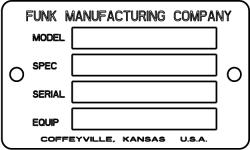
IDENTIFICATION AND SERIAL NUMBER PLATES
The identification plate is located on the engine side and/or opposite engine side of the transmission main case housing. The exact location varies depending on installed options and model number. Earlier version of the DF series transmission had three lines of information. Later DF series transmission will have four lines of information on identification plate. All information on identification plate is needed when contacting FUNK concerning transmission.
Contact:
Funk Manufacturing Company

Attention: Parts Department
Industrial Park, Highway 169 North P.O. Box 577
Coffeyville, Kansas 67337-0577
Telephone: Area Code (800)-844-1337
Ask for Parts Department
FAX:(316)-252-3253
General Information 00-10-3
DF
150
250 160798 PN=14
CTM147 (16JUL98)
Series
and
YZ,CTM147,10,13-19-07MAY98 YZ1502UN24APR98 YZ1503UN01MAY98
RECOMMENDED LUBRICANTS
AMBIENT AIR TEMPERATURE CHART
Select an oil viscosity, from the chart, based on the air temperature range expected between oil changes.
NOTE: The words “oil”, “fluid” and “transmission fluid” are used in this manual to mean, HYDRAULIC TRANSMISSION FLUID, the operating and lubricating oil for this transmission.
Standard and Low viscosity HY-GARD® Transmission fluids are available through the John Deere dealer network worldwide. Other oils may be used if they meet one of the following:
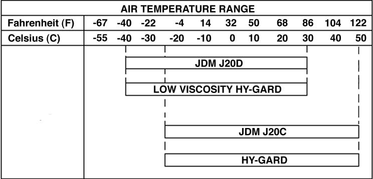
John Deere Standard JDM J20 C
John Deere Standard JDM J20 D
Some fluids that contain the following additive packages have been shown to meet the specification requirements of J20 C and/or J20 D. Inclusion of the following additive packages does not constitute blanket approval of the oil for these applications.
Supplier Additive
Chevron Ornite OLOA 9725X
Lubrizol Lubrizol 9990
General Information 00-10-4 CTM147 (16JUL98) DF Series 150 and 250 160798 PN=14
YZ,CTM147,10,3 -19-05MAY98 YZ1500UN23APR98
HY-GARD is a registered trademark of Deere & Company.
COLD WEATHER STARTUP
Cold starts will sometimes cause the oil filter bypass signal to activate, indicating the oil is bypassing the filter. This should be an intermittent condition and should not continue after the transmission oil has reached 38˚ C (100˚ F) operating temperature.
IMPORTANT: Transmission oil should be warm before operating the transmission. If the transmission (converter out) oil temperature remains below the normal operating range after a reasonable warm-up period, stop the machine and warm the oil by stalling the torque converter.
If necessary to maintain the recommended oil temperature, operate the machine in a higher gear.
STALLING THE TORQUE CONVERTER:
NOTE: This procedure should not be used on 14 inch AAD torque converters.
• Park vehicle away from personnel and obstacles.
• Set brakes.
• Shift transmission to the highest gear.
IMPORTANT: Do not operate transmission at full governed engine rpm for more than 30 seconds. Do not allow converter out oil temperature to exceed 121˚C (250˚F).
• Run engine for a maximum of 30 seconds at full governed engine speed.
• Stop the stall procedure when oil temperature is in the normal operating range. Do not allow oil temperature to exceed 121˚C (250˚F) at anytime.
General Information 00-10-5
(16JUL98)
150
250 160798 PN=5
CTM147
DF Series
and
YZ,CTM54,10,19 -19-07MAY98
COLD WEATHER OPERATION
IMPORTANT: Viscosity grade selection is critical for cold weather operation of the transmission. Preheat and proper start-up procedures are required when operating transmission below the oil’s MINIMUM critical temperature which is viscosity grade dependant.
NOTE: Refer to AIR TEMPERATURE RANGE chart for the MINIMUM transmission operating temperature viscosity grades.
PREHEAT TRANSMISSION FLUID WITH AUXILIARY SOURCE
• Preheat the transmission fluid to the MINIMUM temperature before operating.
ALTERNATE WARM-UP PROCEDURE:
• Operate transmission in neutral for approximately 20 minutes or until oil is warmed to the MINIMUM temperature.
HOT WEATHER OPERATION
Use higher viscosity grades (Refer to AIR TEMPERATURE RANGE chart) for:
• Ambient temperatures consistently above 30˚C (86˚F).
• Frequent stop-and-go driving in hot weather.
• High grade climbing in hot weather.
General Information 00-10-6
(16JUL98)
150
250 160798 PN=17
CTM147
DF Series
and
YZ,CTM147,10,3A-19-05MAY98
FILL THE TRANSMISSION WITH OIL
AFTER INSTALLING TRANSMISSION IN VEHICLE:
• Park machine on level surface.
• Engage parking brake, block wheels.
• Put transmission in neutral.
• Remove dipstick, the dipstick tube is the normal oil fill location.
• Begin filling operation by adding 19 liters (5 gal) of recommended oil.
• Start the engine, run at idle speed to fill the converter and oil lines.
• Check oil level on dip stick with engine running at idle speed.
IMPORTANT: Do not overfill transmission. This will cause overheating. Damage to the transmission will result.
• Fill transmission to the full mark on dipstick with engine running at idle speed.
• Check oil level again when the transmission has reached normal operating temperature 38 93˚C (100 200˚F).
General Information 00-10-7 CTM147 (16JUL98) DF Series 150 and 250 160798 PN=18
YZ,CTM147,10,2 -19-05MAY98
CHECK AND SERVICE TRANSMISSION REGULARLY
Routine checks will help prevent down time. The operator can aid in preventative maintenance by reporting signs of leaks or malfunctions.
The transmission operates in and by oil, most of the maintenance is concerned with oil replenishment and oil cleanliness. The type of service and operating conditions shall determine the maintenance interval.
NOTE: Engage park brake before checking oil level.
OIL LEVEL
IMPORTANT: The DF series transmission should always be in the neutral position before starting the engine, or when the vehicle is parked and the engine is running.
CHECK THE OIL LEVEL DAILY
• Set parking brake.
• Put the gear selector lever in neutral position.
• Operate the engine at idle speed.
• Make sure the transmission oil temperature is at 38 93˚C (100 200˚F).
• Clean area around dipstick before removing.
• Keep oil level at the “FULL” mark on the dipstick.
General Information 00-10-8 CTM147 (16JUL98) DF Series 150 and 250 160798 PN=18
YZ,CTM147,10,1 -19-05MAY98
INTERVALS FOR CHANGING TRANSMISSION OIL AND FILTERS
IMPORTANT: Change oil and filter after the first 50 hours of transmission operation. The oil and filter change intervals given here are for normal service conditions. If the transmission is to be operated in severe conditions contact the Funk Service Department for additional recommendations.
FIRST OIL AND FILTER CHANGE:
• Change oil and filter after first 50 hours of transmission operation.
ROUTINE OIL AND FILTER MAINTENANCE:
IMPORTANT: Some vehicles are equipped with devices to alert the operator when oil is bypassing the filter. Change the oil filter if a “Filter Bypass Signal” is indicated and the transmission is at normal operating temperature.
• Change oil filter anytime the transmission is at normal operating temperature and a “Filter Bypass Signal” is indicated.
• Change oil and filter anytime there are signs of contamination in the oil or the oil has a burnt odor.
• Change filter at every 500 hours, change filter and oil every 1000 hours of transmission operation.
General Information 00-10-9 CTM147 (16JUL98) DF Series 150 and 250 160798 PN=18
YZ,CTM147,10,4 -19-05MAY98
OIL ANALYSIS
Oil analysis is best used by sampling at regular intervals to establish a baseline analysis for the oil and operation conditions present. Changes from this baseline may indicate unusual wear.
IMPORTANT: Change the oil and filter if an analysis of the used transmission oil indicates any of the following limits are exceeded.
• Glycol (Anti-freeze), must not exceed 0% by volume.
• Water, must not exceed 0.05% by volume.
• Viscosity increase at 38˚C (100˚F), not more than 40% over new oil value.
• Total Acid Number (TAN) per ASTM D664, limit of 3.0 over new lubricant value.
OIL TEMPERATURE WARNING SIGNAL
• If the oil temperature gauge, indicating the converter oil-out temperature, rises to 121˚C (250˚F) or the transmission oil temperature warning light comes on, stop the vehicle immediately. Shift to neutral and run the engine at 1000 1200 rpm.
IMPORTANT: Do not stop the engine when the transmission is overheating if the cooling system is known to be in working order.
• The transmission oil temperature should soon lower to the engine water temperature, or if an air-to-oil exchanger is used, the temperature should soon lower to ambient air temperature across the heat exchanger. If the temperature does not lower, trouble is indicated.
• Correct overheating problem before the vehicle is operated again.
General Information 00-10-10
(16JUL98)
150 and 250 160798 PN=10
CTM147
DF Series
YZ,CTM54,10,18 -19-05MAY98
YZ,CTM54,10,20 -19-05MAY98
TOWING THE VEHICLE
AVOID DAMAGE TO TRANSMISSION:
• Run engine at idle speed to lubricate the clutches. Do not exceed normal vehicle speeds while towing.
• If the engine cannot be run: Disconnect drive line from transmission
• If drive line can not be disconnected: Do not exceed 5 km/h (3 mph) Tow no further than 2 km (1 mile)
PUT TRANSMISSION IN STORAGE
This procedure applies to those transmissions and components that have been tested according to Funk Manufacturing test specifications and have had the oil drained from them prior to shipment.
The following actions will help protect the unit and component items from internal rust and corrosion damage for approximately one year, provided the transmissions are stored in a dry area:
• Seal all openings with moisture-proof covers or tape.
• Spray 113 mL (4 oz) of atomized NOX RUST® VCI No. 10 oil or an equivalent into oil drain hole. This fluid is covered and approved per (MIL-P-46002 and MIL-I-23310).
• Dip, spray, or brush all exposed unpainted surfaces with NOX RUST X-110 or an equivalent.
NOX RUST is a trademark of Daubert Chemical Company.
General Information 00-10-11 CTM147 (16JUL98) DF Series 150 and 250 160798 PN=22
YZ,CTM147,10,5
-19-05MAY98
YZ,CTM54,10,17
-19-05MAY98
REMOVE TRANSMISSION FROM STORAGE
• Wash off all external grease with a safety solvent.
• Remove covers or tape from all openings.
• Drain transmission completely.
• Tag transmission to indicate it needs to be filled with oil after installing in vehicle.
General Information
160798 PN=23
00-10-12 CTM147 (16JUL98) DF Series 150 and 250
YZ,CTM147,10,6 -19-10MAR98
INSTALL TRANSMISSION TO THE ENGINE
NCAUTION: Vehicle runaway hazard. Avoid serious or fatal injury. This transmission is not a braking system. Install only if there is a braking system capable of stopping the vehicle with dead engine, disengaged transmission, or loss of hydrostatic retardation. Otherwise, vehicle may roll freely, resulting in loss of control.
1. Check engine crankshaft endplay, it should comply with engine manufactures tolerances.
2. Remove the flywheel housing access cover. Rotate the engine flywheel until one of the mounting holes for the drive plate is aligned with the flywheel housing access hole.
3. Support the transmission assembly so that it can be positioned directly in line with the engine crankshaft. Align the pilot sleeve with the flywheel pilot bore. Align one of the cap screw holes in the drive plate with one of the mounting holes in the flywheel.
IMPORTANT: If the transmission does not close up to the flywheel, do not proceed, Forcing the transmission up to the engine with the assembly bolts could preload the engine crankshaft and cause engine or transmission problems later, Remove the transmission and check previous assembly steps to determine the problem. Take corrective action before proceeding.
4. Push the transmission to the engine.
5. Fasten the transmission input housing (converter housing) to the engine flywheel housing.
6. Attach the drive plate to the flywheel. Install and hand tighten cap screws through the engine flywheel housing access hole. After all the cap screws have been installed, tighten to proper torque values.
IMPORTANT: Check the engine crankshaft endplay.
7. Check the engine crankshaft endplay. It should comply with the engine manufacturer’s specifications. If end play is less than specified the crankshaft may have been preloaded at assembly with the transmission. The engine should not be run until the preload condition is corrected.
8. Install the flywheel access hole cover.
9. Connect all drive line, mechanical linkages, hydraulic lines and electronic connectors required by transmission.
10. Fill transmission with oil as described in this section of the manual.
General Information 00-10-13 CTM147 (16JUL98) DF Series 150 and 250 160798 PN=23
YZ,CTM147,10,7 -19-05MAY98
CONVERTER-TO-ENGINE FLYWHEEL DIMENSIONS

General Information
00-10-14
CTM147 (16JUL98)
160798 PN=14
DF Series 150 and 250
1-Engine Flywheel Housing
2-Converter Drive Plate Group
3-Converter Pilot Sleeve
4-Engine Crank Shaft
5-Engine Flywheel
6-Converter Assembly
7-Housing Spacer (as required)
8-Flywheel End Stop
9-Flywheel Shoulder Stop
10-Pilot Sleeve End Stop
11-Pilot Sleeve Shoulder Stop
YZ710UN25OCT93
YZ,CTM147,10,37-19-05MAY98
ENGINE TO TORQUE CONVERTER SPECIFICATIONS
IMPORTANT: Engine to torque converter dimensions must be checked anytime the following has occurred:
CHECK THE ENGINE TO TORQUE CONVERTER SPECIFICATIONS ANYTIME:
• The engine has been changed.
• The engine flywheel has been changed.
• The engine flywheel housing has been changed.
• The torque converter has been replaced with a different part number.
• The drive plate has been replaced with a different part number.
1. Dimension “U” 165.1 mm (6.50) minimum to clear the drive plate and converter assembly.
2. Check and determine the type of pilot sleeve that is being used in your application (end stop or shoulder stop).
3. Check dimension “Y” and “Z” on the flywheel depending on the type of pilot sleeve, measure dimension “Z” from flywheel drive plate mounting face to the flywheel pilot bore stop in the bottom of the pilot bore on dimension “Y” on the flywheel from flywheel drive plate mounting face to the flywheel pilot bore shoulder stop.
4. Place sleeve on the converter front cover pilot knob and push back to the converter front cover. Check dimension “Y” or “Z” on the converter drive plate pilot sleeve assembly depending on the type of pilot sleeve, or measure dimension “Y” from the drive plate mounting face that will be mounted to the flywheel out to the shoulder on the pilot sleeve.
See preceding page for drawing with installation dimensions.
Standard length pilot sleeves are setup for 2.046/2.048, 2.44/2.442 and 2.833/2.835 flywheel pilot bores and dimension “Z” 33.4 ± 0.2 mm (1.315 ± .01) from the flywheel drive plate mounting face to the flywheel pilot bore stop in the bottom of the pilot bore.
CHECK THE FOLLOWING ENGINE AND TRANSMISSION DIMENSIONS TO ASSURE PROPER INSTALLATION:
5. The converter, drive plate and pilot assembly dimension “Z” or “Y” (step 4) should be .03 to .10 shorter than flywheel dimension “Z” or “Y” (step 3). The pilot sleeve is not preloaded between the converter assembly and flywheel.
6. Check the diameter of the flywheel pilot bore dimension “M” and converter pilot sleeve dimension “A” for a proper fit. There should be 0.01 0.07 mm (0.0005 0.003 in.) diametric clearance. Flywheels that do not fit within this tolerance will require a special sleeve to accurately pilot the converter assembly. If the above dimensions check out, the assembly can continue.
7. Check the engine crankshaft endplay. It should comply with the engine manufacturer’s tolerance.
General Information 00-10-15
(16JUL98)
Series 150 and 250 160798 PN=26
CTM147
DF
B= FLYWHEEL HOUSING FACE TO FLYWHEEL FACE Z+0.2 -0.2 mm “B” “R” (Z+0.01 -0.01 in.) REFERENCE MAXIMUM STANDARD46.2 mm 53.3 mm 31.7 mm (1.82 in) (2.12 in) (1.25 in)
SPECIAL FLYWHEEL APPLICATIONS
YZ,CTM147,10,32-19-05MAY98
SUGGESTED WRENCHING TORQUE FOR TAPERED PIPE THREAD
TAPERED PIPE THREAD WITH SEALANT CHART
TAPERED PIPE THREAD WITHOUT SEALANT CHART
General Information
00-10-16
CTM147 (16JUL98)
160798 PN=28
DF Series 150 and 250
Thread Size N·m lb-ft
Thread Size N·m lb-ft
TORQUE
TAPERED PIPE THREAD charts meet Funk Engineering Procedures Manual Torque Specifications FEP 14.4. CTM147,10,41 -19-05MAY98 1/16-27 UNF 15 10 1/8-27 UNF 20 15 1/4-18 UNF 25 20 3/8-18 UNF 35 25 1/2-14 UNF 45 35 3/4-14 UNF 60 45 1-11 1/2 UN 75 55 1-1/4-11 1/2 UN 95 70 1-1/2-11 1/2 UN 110 80 2-11 1/2 UN 130 95 1/16-27 UNF 20 15 1/8-27 UNF 25 20 1/4-18 UNF 35 25 3/8-18 UNF 45 35 1/2-14 UNF 60 45 3/4-14 UNF 75 55 1-11 1/2 UN 90 65 1-1/4-11 1/2 UN 110 80 1-1/2-11 1/2 UN 130 95 2-11 1/2 UN 160 120
SUGGESTED WRENCHING
FOR
SERVICE RECOMMENDATIONS FOR O-RING BOSS FITTINGS
STRAIGHT FITTING
1. Inspect O-ring boss seat for dirt or defects.
2. Lubricate O-ring with petroleum jelly. Place electrical tape over threads to protect O-ring. Slide O-ring over tape and into O-ring groove of fitting. Remove tape.
3. Tighten fitting to torque value shown on chart.


ANGLE FITTING
1. Back-off lock nut (A) and back-up washer (B) completely to head-end (C) of fitting.
2. Turn fitting into threaded boss until back-up washer contacts face of boss.
3. Turn fitting head-end counterclockwise to proper index (maximum of one turn).
NOTE: Do not allow hoses to twist when tightening fittings.
4. Hold fitting head-end with a wrench and tighten locknut and back-up washer to proper torque value.
NOTE: Torque tolerance is + 15% -20%.
SERVICE RECOMMENDATIONS FOR O-RING BOSS FITTINGS chart meets Funk Engineering Procedures Manual Torque Specifications FEP 14.3.
(16JUL98)
00-10-17
General Information
160798 PN=28
CTM147
DF Series 150 and 250
STRAIGHT FITTING OR SPECIAL NUT TORQUE CHART Thread Size N·m lb-ft 3/8-24 UNF 8 6 7/16-20 UNF 12 9 1/2-20 UNF 16 12 9/16-18 UNF 24 18 3/4-16 UNF 46 34 7/8-14 UNF 62 46 1-1/16-12 UN 102 75 1-3/16-12 UN 122 90 1-5/16-12 UN 142 105 1-5/8-12 UN 190 140 1-7/8-12 UN 217 160
CTM147,10,40 -19-05MAY98 T6520ABUN18OCT88 T6243AEUN18OCT88