COMPONENT TECHNICAL MANUAL


PowerTech® 4.5 & 6.8 L Diesel
Engines—Level 12 Electronic Fuel System with DE10 Pump
CTM331 09APR02 (English)
Level 12 Electronic Fuel System With Stanadyne DE10 Pump
TECHNICAL MANUAL
CTM331 09APR02 (ENGLISH)
For complete service information also see: P
OWERTECH 4.5L & 6.8L
P
Diesel Engines
POWERTECH 4.5 L & 6.8 L Diesel Engines—Level 12 Electronic Fuel System with DE10 Pump
. . . . . . . . .
LITHO IN U.S.A.
OWERTECH
4.5 L and 6.8 L Diesel Engines Base Engine ..........................................CTM104 Alternators and Starter Motors.
. CTM77 OEM Engine Accessories..............CTM67 (English Only) John Deere Power Systems
This manual is written for an experienced technician. Essential tools required in performing certain service work are identified in this manual and are recommended for use.
This manual (CTM331) covers only Level 12 Electronic Fuel System with the Stanadyne DE10 injection pump. It is one of five volumes on 4.5 L and 6.8 L engines. The following four companion manuals cover the base engine, mechanical fuel system, level 4 electronic fuel system and level 1 electronic fuel system repair, operation and diagnostics:
• CTM104 Base Engine
• CTM170 Level 4 Electronic Fuel System with Bosch VP44 Pump
• CTM207 Mechanical Fuel Systems
• CTM284 Level 1 Electronic Fuel Systems with Delphi (Lucas) DP201 Pump
Other manuals will be added in the future to provide additional information on electronic fuel systems as needed.
Live with safety: Read the safety messages in the introduction of this manual and the cautions presented throughout the text of the manual.
This is the safety-alert symbol. When you see this symbol on the machine or in this manual, be alert to the potential for personal injury.

Use this component technical manual in conjunction with the machine technical manual. An application listing in Section 01, Group 001 identifies product-model/component type-model relationship. See the machine technical manual for information on
component removal and installation, and gaining access to the components.
Information is organized in sections and groups for the various components requiring service instruction. Section 05 summarizes all applicable essential tools, service equipment and tools, other materials needed to do the job, and service parts kits. Section 06 summarizes all specifications, wear tolerances, and torque values.
Before beginning diagnosis or repair on an engine, clean the engine.
This manual contains SI Metric units of measure followed immediately by the U.S. customary units of measure. Most hardware on these engines is metric sized.
Some components of this engine may be serviced without removing the engine from the machine. Refer to the specific machine technical manual for information on components that can be serviced without removing the engine from the machine and for engine removal and installation procedures.
Read each block of material completely before performing service to check for differences in procedures or specifications. Follow only the procedures that apply to the engine model number you are working on. If only one procedure is given, that procedure applies to all the engines in the manual.
CALIFORNIA PROPOSITION 65 WARNING
Diesel engine exhaust and some of its constituents are known to the State of California to cause cancer, birth defects and other reproductive harm.
CTM331 (09APR02) 4.5 L & 6.8 L Level 12 Electronic Fuel System 040902 PN=2 Forward
OUO1080,00001FE –19–16NOV01–1/1 Introduction
Introduction CTM331 (09APR02) 4.5 L & 6.8 L Level 12 Electronic Fuel System 040902 PN=3 POWERTECH
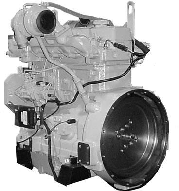
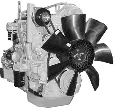
Pump
Side of Engine
Side of Engine POWERTECH is a registered trademark of Deere & Company DPSG,OUO1004,129 –19–15MAY98–1/1 RG11931 –UN –06NOV01 RG11932 –UN –06NOV01
4.5 L Engine with Level 12 Electronic Fuel System and Stanadyne DE10
Left
Right
Introduction CTM331 (09APR02) 4.5 L & 6.8 L Level 12 Electronic Fuel System 040902 PN=4
SECTION 01—General Information
Group 000 Safety
Group 001 Engine Identification
Group 002 Fuels
SECTION 02 Repair and Adjustments
Group 090 Electronic Fuel System Repair and Adjustments
Group 110 Electrical Engine Control Repair and Adjustment
SECTION 03—Theory of Operation
Group 130 Electronic Fuel System Operation
Group 140 Electronic Control System Operation
SECTION 04 Diagnostics
Group 150 Observable Diagnostics and Tests
Group 160 Trouble Code Diagnostics and Tests
SECTION 05
Tools and Other Materials
Group 170 Electronic Fuel/Control System Repair Tools and Other Materials
Group 180 Diagnostic Service Tools
SECTION 06—Specifications
Group 200 Repair Specifications
Group 210 Diagnostic Specifications
All information, illustrations and specifications in this manual are based on the latest information available at the time of publication. The right is reserved to make changes at any time without notice.
i CTM331 (09APR02) 4.5 L & 6.8 L Level 12 Electronic Fuel System 040902 PN=1
COPYRIGHT © 2002 DEERE & COMPANY Moline, Illinois All rights reserved A John Deere ILLUSTRUCTION Manual 01 02 03 04 05 06 INDX Contents
ii CTM331 (09APR02) 4.5 L & 6.8 L Level 12 Electronic Fuel System 040902 PN=2 01 02 03 04 05 06 INDX Contents
01-1 CTM331 (09APR02) 4.5 L & 6.8 L Level 12 Electronic Fuel System 040902 PN=1 01 Section 01 General Information Contents Page Group 000—Safety.......................................... 01-000-1 Group 001—Engine Identification Engine Model Designation 01-001-1 Engine Serial Number Plate Information..........01-001-2 OEM Engine Option Code Label......................01-001-3 Information Relative to Emissions Regulations 01-001-3 Engine Application Charts 01-001-4 Group 002 Fuels Lubricants and Coolant 01-002-1 Diesel Fuel 01-002-1 Bio-Diesel Fuel..................................................01-002-2 Dieselscan Fuel Analysis..................................01-002-2 Lubricity of Diesel Fuel .....................................01-002-3
01-2 CTM331 (09APR02) 4.5 L & 6.8 L Level 12 Electronic Fuel System 040902 PN=2 01 Contents
Handle Fluids Safely—Avoid Fires
When you work around fuel, do not smoke or work near heaters or other fire hazards.

Store flammable fluids away from fire hazards. Do not incinerate or puncture pressurized containers.
Make sure machine is clean of trash, grease, and debris.
Do not store oily rags; they can ignite and burn spontaneously.
Handle Starting Fluid Safely
Starting fluid is highly flammable.
Keep all sparks and flame away when using it. Keep starting fluid away from batteries and cables.
To prevent accidental discharge when storing the pressurized can, keep the cap on the container, and store in a cool, protected location.
Do not incinerate or puncture a starting fluid container.
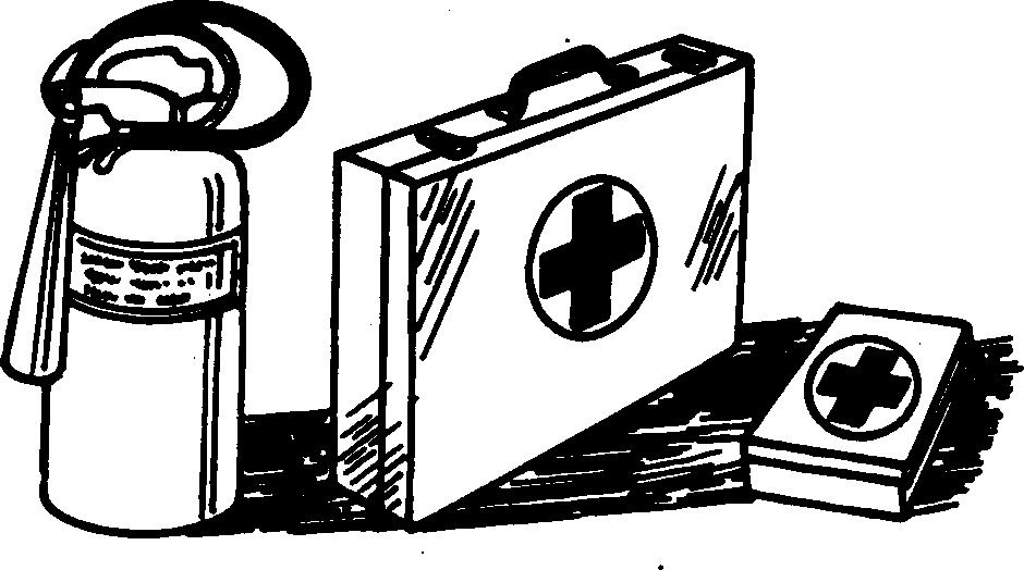
Prepare for Emergencies
Be prepared if a fire starts.
Keep a first aid kit and fire extinguisher handy.
Keep emergency numbers for doctors, ambulance service, hospital, and fire department near your telephone.
040902 PN=9 TS227 –UN –23AUG88
01 000 1
DX,FLAME –19–29SEP98–1/1 CTM331 (09APR02) 01-000-1 4.5 L & 6.8 L Level 12 Electronic Fuel System Group 000 Safety
DX,FIRE3 –19–16APR92–1/1
DX,FIRE2 –19–03MAR93–1/1 TS291 –UN –23AUG88 TS1356 –UN –18MAR92
Avoid High-Pressure Fluids
Escaping fluid under pressure can penetrate the skin causing serious injury.
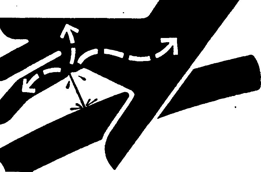
Avoid the hazard by relieving pressure before disconnecting hydraulic or other lines. Tighten all connections before applying pressure.
Search for leaks with a piece of cardboard. Protect hands and body from high pressure fluids.
If an accident occurs, see a doctor immediately. Any fluid injected into the skin must be surgically removed within a few hours or gangrene may result. Doctors unfamiliar with this type of injury should reference a knowledgeable medical source. Such information is available from Deere & Company Medical Department in Moline, Illinois, U.S.A.
Wear Protective Clothing
Wear close fitting clothing and safety equipment appropriate to the job.
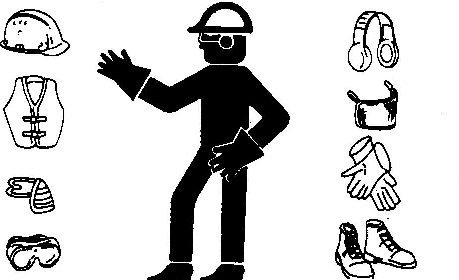
Prolonged exposure to loud noise can cause impairment or loss of hearing.
Wear a suitable hearing protective device such as earmuffs or earplugs to protect against objectionable or uncomfortable loud noises.
Operating equipment safely requires the full attention of the operator. Do not wear radio or music headphones while operating machine.
Safety 01-000-2 CTM331 (09APR02) 4.5 L & 6.8 L Level 12 Electronic Fuel System 040902 PN=10 01 000 2
DX,FLUID –19–03MAR93–1/1
DX,WEAR –19–10SEP90–1/1 X9811 –UN –23AUG88 TS206 –UN –23AUG88
Service Machines Safely
Tie long hair behind your head. Do not wear a necktie, scarf, loose clothing, or necklace when you work near machine tools or moving parts. If these items were to get caught, severe injury could result.

Remove rings and other jewelry to prevent electrical shorts and entanglement in moving parts.
Work In Ventilated Area
Engine exhaust fumes can cause sickness or death. If it is necessary to run an engine in an enclosed area, remove the exhaust fumes from the area with an exhaust pipe extension.
If you do not have an exhaust pipe extension, open the doors and get outside air into the area
Work in Clean Area
Before starting a job:
• Clean work area and machine.
• Make sure you have all necessary tools to do your job.
• Have the right parts on hand.
• Read all instructions thoroughly; do not attempt shortcuts.
Safety 01-000-3 CTM331 (09APR02) 4.5 L & 6.8 L Level 12 Electronic Fuel System 040902 PN=11 TS228 –UN –23AUG88
01 000 3
DX,LOOSE –19–04JUN90–1/1
DX,AIR –19–17FEB99–1/1
DX,CLEAN –19–04JUN90–1/1 T6642EJ –UN –18OCT88 TS220 –UN –23AUG88
Remove Paint Before Welding or Heating
Avoid potentially toxic fumes and dust.
Hazardous fumes can be generated when paint is heated by welding, soldering, or using a torch. Remove paint before heating:
• Remove paint a minimum of 76 mm (3 in.) from area to be affected by heating.
• If you sand or grind paint, avoid breathing the dust. Wear an approved respirator.
• If you use solvent or paint stripper, remove stripper with soap and water before welding. Remove solvent or paint stripper containers and other flammable material from area. Allow fumes to disperse at least 15 minutes before welding or heating.
Do not use a chlorinated solvent in areas where welding will take place.
Do all work in an area that is well ventilated to carry toxic fumes and dust away.
Dispose of paint and solvent properly.
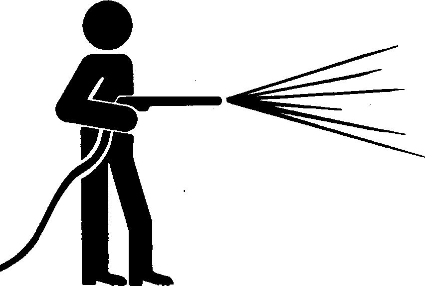
Avoid Heating Near Pressurized Fluid Lines
Flammable spray can be generated by heating near pressurized fluid lines, resulting in severe burns to yourself and bystanders. Do not heat by welding, soldering, or using a torch near pressurized fluid lines or other flammable materials. Pressurized lines can be accidentally cut when heat goes beyond the immediate flame area.

Safety 01-000-4 CTM331 (09APR02) 4.5 L & 6.8 L Level 12 Electronic Fuel System 040902 PN=12 01 000 4
DX,PAINT –19–19JUL01–1/1
DX,TORCH –19–03MAR93–1/1 TS953 –UN –15MAY90 TS220 –UN –23AUG88
Illuminate Work Area Safely
Illuminate your work area adequately but safely. Use a portable safety light for working inside or under the machine. Make sure the bulb is enclosed by a wire cage. The hot filament of an accidentally broken bulb can ignite spilled fuel or oil.
Construct Dealer-Made Tools Safely
Faulty or broken tools can result in serious injury. When constructing tools, use proper, quality materials, and good workmanship.
Do not weld tools unless you have the proper equipment and experience to perform the job.
Safety 01-000-5 CTM331 (09APR02) 4.5 L & 6.8 L Level 12 Electronic Fuel System 040902 PN=13 TS223 –UN –23AUG88
01 000 5
DX,LIGHT –19–04JUN90–1/1
DX,SAFE,TOOLS –19–10OCT97–1/1 LX1016749 –UN –01JUL97
Practice Safe Maintenance
Understand service procedure before doing work. Keep area clean and dry.
Never lubricate, service, or adjust machine while it is moving. Keep hands, feet , and clothing from power-driven parts. Disengage all power and operate controls to relieve pressure. Lower equipment to the ground. Stop the engine. Remove the key. Allow machine to cool.
Securely support any machine elements that must be raised for service work.
Keep all parts in good condition and properly installed. Fix damage immediately. Replace worn or broken parts. Remove any buildup of grease, oil, or debris.
On self-propelled equipment, disconnect battery ground cable ( ) before making adjustments on electrical systems or welding on machine.
On towed implements, disconnect wiring harnesses from tractor before servicing electrical system components or welding on machine.
Use Proper Tools
Use tools appropriate to the work. Makeshift tools and procedures can create safety hazards.

Use power tools only to loosen threaded parts and fasteners.
For loosening and tightening hardware, use the correct size tools. DO NOT use U.S. measurement tools on metric fasteners. Avoid bodily injury caused by slipping wrenches.
Use only service parts meeting John Deere specifications.
Safety 01-000-6 CTM331 (09APR02) 4.5 L & 6.8 L Level 12 Electronic Fuel System 040902 PN=14 01 000 6
DX,SERV –19–17FEB99–1/1
DX,REPAIR –19–17FEB99–1/1 TS779 –UN –08NOV89 TS218 –UN –23AUG88
Dispose of Waste Properly
Improperly disposing of waste can threaten the environment and ecology. Potentially harmful waste used with John Deere equipment include such items as oil, fuel, coolant, brake fluid, filters, and batteries.
Use leakproof containers when draining fluids. Do not use food or beverage containers that may mislead someone into drinking from them.
Do not pour waste onto the ground, down a drain, or into any water source.
Air conditioning refrigerants escaping into the air can damage the Earth’s atmosphere. Government regulations may require a certified air conditioning service center to recover and recycle used air conditioning refrigerants.
Inquire on the proper way to recycle or dispose of waste from your local environmental or recycling center, or from your John Deere dealer.

Live With Safety
Before returning machine to customer, make sure machine is functioning properly, especially the safety systems. Install all guards and shields.

Safety 01-000-7 CTM331 (09APR02) 4.5 L & 6.8 L Level 12 Electronic Fuel System 040902 PN=15 TS1133 –UN –26NOV90
01 000 7
DX,DRAIN –19–03MAR93–1/1
DX,LIVE –19–25SEP92–1/1 TS231 –19 –07OCT88
Safety 01-000-8 CTM331 (09APR02) 4.5 L & 6.8 L Level 12 Electronic Fuel System 040902 PN=16 01 000 8
Engine Identification
Engine Model Designation
John Deere Engine Model 4045 and 6068 Engines
John Deere engine model designation includes number of cylinders, displacement in liters, aspiration, user code, and application code. For example:
4045TF275 Engine
4
4.5
T
F
275
Aspiration Code
D
T
A
H
User Factory Code
AT
CQ
DW
E
F
FF
FG
FM
H
KV
L
LA
LV
N
P
PY
RW
T
Number of cylinders
Liter displacement
Aspiration code
User code
POWERTECH application code
Naturally aspirated
Turbocharged, no aftercooling
Turbocharged and Air-to-Coolant Aftercooled
Turbocharged and Air-to-Air Aftercooled
Agritalia srl (Vittoria, Sicily, Italy)
John Deere Brazil (Horizontina, Brazil)
John Deere Davenport Works (Davenport, Iowa)
John Deere Ottumwa Works (Ottumwa, Iowa)
OEM (Outside Equipment Manufacturers)
Deere-Hitachi (Kernersville, North Carolina)
Goldoni S.P.A. (Modena, Italy)
Marine Engines
John Deere Harvester Works (East Moline, Illinois)
John Deere Commercial Worksite Products (Knoxville, Tennessee)
John Deere Werke Mannheim (Germany)
John Deere Werke Mannheim (Germany) (Engines with Bosch VP44 Injection Pump)
John Deere Commercial Products (Augusta, Georgia)
John Deere Des Moines Works (Des Moines, Iowa)
Industrias John Deere Mexico S.A. de C.V. (Saltillo/Monterrey, Mexico)
Larson & Toubro Ltd. (Pune, India)
John Deere Waterloo Tractor Works (Waterloo, Iowa)
John Deere Dubuque Works (Dubuque, Iowa)
T8 Cameco Industries (Thibodaux, Louisiana)
TJ Timberjack (Deere) (Sweden/Finland/Canada)
YC
Z
Application Code 001, etc.
John Deere Jialian Harvester Co. Limited (China)
John Deere WERKE Zweibrucken (Germany)
See ENGINE APPLICATION CHARTS, later in this Group
01-001-1
4.5 L & 6.8 L Level 12 Electronic Fuel System 040902 PN=17
CTM331 (09APR02)
01 001 1 POWERTECH is a registered trademark of Deere & Company OUO1080,00001FA –19–15NOV01–1/1
Group 001
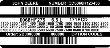
Engine Serial Number Plate Information
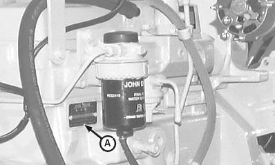
IMPORTANT: The engine serial number plate (A) can be easily destroyed. Before “hot tank” cleaning the block, remove the plate.
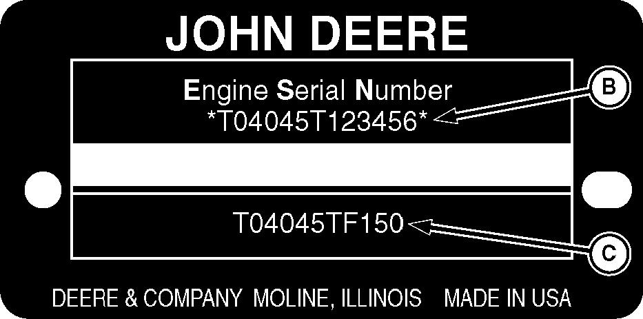
Engine Serial Number (B)
Each engine has a 13-digit John Deere engine serial number identifying the producing factory, engine model designation, and a 6-digit sequential number. The following is an example:
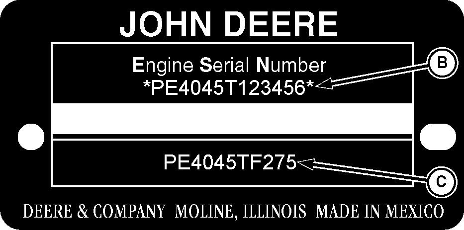
CD4045T000000
CD Factory producing engine
4045T Engine model designation
000000 Sequential serial number
Factory Code (Engine Manufacturer)
T0 Dubuque, Iowa
CD Saran, France
PE Torreon, Mexico
J0 Rosario, Argentina
Engine Model Designation
4045T Definition explained previously. See ENGINE MODEL DESIGNATION earlier in this group.
Sequential Number
000000 6-digit sequential serial number
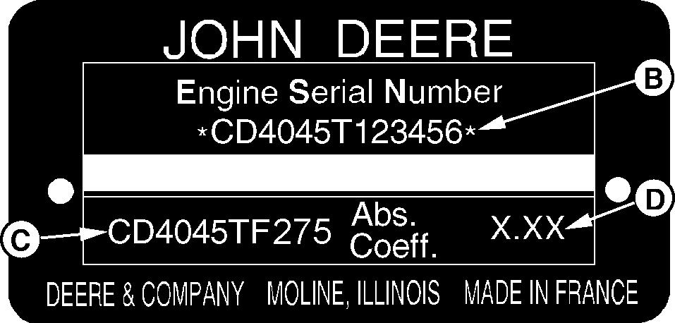
Engine Application Data (C)
The second line of information on the serial number plate identifies the engine/machine or OEM relationship. See ENGINE APPLICATION CHARTS later in this group.
Coefficient of Absorption (D) (Saran-Built Engines Only)
The second line of information on the Saran serial number plate also contains the coefficient of absorption value for smoke emissions.
A Engine Serial Number Plate B
Engine Serial Number C Engine Application Data
D Coefficient of Absorption (Saran Engines Only)
01-001-2 CTM331 (09APR02) 4.5 L & 6.8 L Level 12 Electronic Fuel System 040902 PN=18 01 001 2
Engine Identification
Engine Serial Number Plate
Dubuque Engine Serial Number Plate
Number Plate OUO1080,00001FB –19–15NOV01–1/1 RG11949 –UN –07NOV01 RG11948 –UN –06NOV01 RG9060 –UN –16MAR98 RG11816 –UN –15NOV01
Saran Engine Serial Number Plate Torreon Engine
Serial
OEM Engine Option Code Label
An option code label is secured to the top of the valve cover and identifies the factory installed options on each OEM engine to ensure correct parts acquisition.
Always provide option code information and engine base code when ordering repair parts. A listing of option codes is given in parts catalogs and operator’s manuals.
NOTE: Before “hot tank” cleaning, ensure that option codes are recorded elsewhere.
Information Relative to Emissions Regulations
Depending on the final destination, engines can meet the emissions regulations according to the US Environmental Protection Agency (EPA), California Air Resources Board (CARB) and for Europe, the Directive 97/68/EC relating the measures against the emissions of particles and gaseous pollutant from internal combustion engines. Such engines are called “CERTIFIED” and receive an emission label stuck on the engine.
The regulations prohibit tampering with the emission-related components listed below which would render that component inoperative or to make any adjustment on the engine beyond published specifications. It is also illegal to install a part or
component where the principle effect of that component is to bypass, defeat, or render inoperative any engine component or device which would affect the engine’s conformance to the emission regulations. To summarize, it is illegal to do anything except return the engine to its original published specifications.
List of emission-related components:
• Fuel injection system
• Intake manifold
• Turbocharger
• Charge air cooling system
• Piston
Identification 01-001-3 CTM331 (09APR02) 4.5 L & 6.8 L Level 12 Electronic Fuel System 040902 PN=19 RG12027 –UN –03DEC01
Engine
01 001 3
OUO1080,000020E –19–26NOV01–1/1
OUO1080,0000035 –19–29AUG01–1/1
Engine Application Charts
JOHN DEERE CONSTRUCTION & FORESTRY EQUIPMENT
Machine Model Engine Model
Dubuque
310G Backhoe Loader (XXXXXX )
310G Backhoe Loader (Alt Comp) (XXXXXX )
310SG Backhoe Loader (XXXXXX )
315SG Backhoe Loader (XXXXXX )
450H Crawler Dozer (Alt Comp) (XXXXXX )
450H Crawler Dozer (Nat Asp) (XXXXXX )
450H LGP Crawler Dozer (XXXXXX )
550H Crawler Dozer (XXXXXX )
550H LGP Crawler Dozer (XXXXXX )
Saltillo, Mexico
120C Excavator
160C LC Excavator
Timberjack
810 Forwarder
1010 (1058) Forwarder
1410 (1458) Forwarder
770 (863) Harvester
1070 (1063) Harvester
PE4045DT058, T04045DT058
PE4045TT088, T04045TT088
PE4045TT089, T04045TT089
PE4045TT084, T04045TT084
PE4045DT058, T04045DT058
PE4045TT085, T04045TT085
PE4045TT087, T04045TT087
PE4045TT086, T04045TT086
PE4045HP050
PE4045HP051
CD4045HTJ01
T04045HTJ76
CD6068HTJ02
CD4045HTJ03
CD6068HTJ03
JOHN DEERE AGRICULTURAL EQUIPMENT
Machine Model Engine Model
Zweibrucken, Germany
3800 TeleHandler
JOHN DEERE OEM (OUTSIDE EQUIPMENT MANUFACTURERS)
CD4045TF275
PE4045HF275
CD4045TF275
PE4045TF275
CD6068HF275
PE6068HF275
CD6068TF275
PE6068TF275
CD4045HZ050
01-001-4
4.5 L & 6.8 L Level 12 Electronic Fuel System 040902 PN=20 01 001 4
Engine Identification
CTM331 (09APR02)
OUO1089,0000205 –19–09NOV01–1/1
NOTE: Refer to Section 01, Group 002 of CTM104 Base Engine Manual for information on lubricants and coolants.
Diesel Fuel
Consult your local fuel distributor for properties of the diesel fuel available in your area.
In general, diesel fuels are blended to satisfy the low temperature requirements of the geographical area in which they are marketed.
Diesel fuels specified to EN 590 or ASTM D975 are recommended.
Required fuel properties
In all cases, the fuel must meet the following properties:
Cetane number of 45 minimum. Cetane number greater than 50 is preferred, especially for temperatures below -20C (-4F) or elevations above 1500 m (5000 ft).
Fuel lubricity should pass a minimum load level of 3100 grams as measured by ASTM D6078 or, maximum scar diameter of 0.45 mm as measured by ASTM D6079.
Sulfur content:
• Diesel fuel quality and fuel sulfur content must comply with all existing regulations for the area in which the engine operates.
• Sulfur content less than 0.05% (500 ppm) is preferred.
• If diesel fuel with sulfur content greater than 0.05% (500 ppm) is used, crankcse oil service intervals may be affected. (See recommendation for Diesel Engine Oil.)
• DO NOT use diesel fuel with sulfur content greater than 1.0%.
IMPORTANT: DO NOT mix used engine oil or any Cold Filter Plugging Point (CFPP) below the other type of lubricating oil with expected low temperature OR Cloud Point at least diesel fuel. 5C (9F) below the expected low temperature.
01-002-1 CTM331 (09APR02) 4.5 L & 6.8 L Level 12 Electronic Fuel System 040902 PN=21
OUOD002,0000171 –19–18DEC01–1/1 Lubricants and Coolant 01 002 1
DPSG,OUO1004,2761 –19–16MAY00–1/1
Group 002 Fuels
Bio-Diesel Fuel
Consult your local fuel distributor for properties of the bio-diesel fuel available in your area.
Bio-diesel fuels may be used ONLY if the bio-diesel fuel properties meet the latest edition of ASTM PS121, DIN 51606 or equivalent specification.
It has been found that bio-diesel fuels may improve lubricity in concentrations up to a 5% blend in petroleum diesel fuel.
When using a blend of bio-diesel fuel, the engine oil level must be checked daily when the air temperature is -10C (14F) or lower. If the oil becomes diluted with fuel, shorten oil change intervals accordingly.
IMPORTANT: Raw pressed vegetable oils are NOT acceptable for use for fuel in any concentration in John Deere engines.
These oils do not burn completely, and will cause engine failure by leaving deposits on injectors and in the combustion chamber.
A major environmental benefit of bio-diesel fuel is its ability to biodegrade. This makes proper storage and handling of bio-diesel fuel especially important. Areas of concern include:
• Quality of new fuel
• Water content of the fuel
• Problems due to aging of the fuel
Potential problems resulting from deficiencies in the above areas when using bio-diesel fuel in concentrations above 5% may lead to the following symptoms:
• Power loss and deterioration of performance
• Fuel leakage
• Corrosion of fuel injection equipment
• Coked and/or blocked injector nozzles, resulting in engine misfire
• Filter plugging
• Lacquering and/or seizure of internal components
• Sludge and sediments
• Reduced service life of engine components
Dieselscan Fuel Analysis
DIESELSCAN is a John Deere fuel sampling program to help you monitor the quality of your fuel source. It verifies fuel type, cleanliness, water content, suitability for cold weather operation, and if fuel is within ASTM specifications. Check with your John Deere dealer for availability of DIESELSCAN kits.
DIESELSCAN is a trademark of Deere & Company
Fuels 01-002-2 CTM331
4.5 L & 6.8 L Level 12 Electronic Fuel System 040902 PN=22
(09APR02)
DX,FUEL6 –19–06DEC00–1/1 01 002 2
RG41183,0000046 –19–18DEC01–1/1
Lubricity of Diesel Fuel
Diesel fuel must have adequate lubricity to ensure Use of low lubricity diesel fuels may also cause proper operation and durability of fuel injection system accelerated wear, injection nozzle erosion or corrosion, components. engine speed instability, hard starting, low power, and engine smoke.
Diesel fuels for highway use in the United States and Canada require sulfur content less than 0.05% (500 Fuel lubricity should pass a minimum load level of ppm). 3100 gram as measured by the ASTM D6078 or maximum scar diameter of 0.45 mm as measured by Diesel fuel in the European Union requires sulfur ASTM D6079. content less than 0.05% (500 ppm).
ASTM D975 and EN 590 specifications do not require Experience shows that some low sulfur diesel fuels fuels to pass a fuel lubricity test. may have inadequate lubricity and their use may reduce performance in fuel injection systems due to If fuel of low or unknown lubricity is used, add John inadequate lubrication of injection pump components. Deere PREMIUM DIESEL FUEL CONDITIONER (or The lower concentration of aromatic compounds in equivalent) at the specified concentration. these fuels also adversely affects injection pump seals and may result in leaks.
Fuels 01-002-3 CTM331 (09APR02) 4.5 L & 6.8 L Level 12 Electronic Fuel System 040902 PN=23
01 002 3
OUOD002,0000179 –19–18DEC01–1/1
Fuels 01-002-4 CTM331 (09APR02) 4.5 L & 6.8 L Level 12 Electronic Fuel System 040902 PN=24 01 002 4
02-1 CTM331 (09APR02) 4.5 L & 6.8 L Level 12 Electronic Fuel System 040902 PN=1 Section 02 Repair and Adjustments Contents 02 Page Page Group 090 Electronic Fuel System Repair and Remove Blade Terminals from Connector Adjustments Body ............................................................02-110-11 Fuel System General Information . . . . . . . . .02-090-1 Repair (Pull Type) METRI-PACK Relieve Fuel System Pressure . . . . . . . . . . . .02-090-1 Connectors 02-110-12 Remove and Install Final Fuel Filter/Water Repair (Push Type) METRI-PACK Bowl and/or Pre-Filter/Water Bowl Base . . .02-090-2 Connectors 02-110-14 Fuel Pre-Filter/Water Bowl Assembly Repair DEUTSCH Connectors 02-110-17 (Optional). .02-090-5 Repair AMP Connector 02-110-20 Final Fuel Filter Assembly ................................02-090-6 Replace Final Fuel Filter/Water Bowl and Pre-Filter/Water Bowl 02-090-7 Remove Fuel Supply Pump 02-090-9 Install Fuel Supply Pump 02-090-10 Injection Pump Static Timing..........................02-090-10 Remove Injection Pump..................................02-090-11 Inspect Injection Pump Drive Gear ID and Shaft OD......................................................02-090-13 Install Injection Pump 02-090-13 Remove Fuel Injection Nozzles 02-090-16 Clean Fuel Injection Nozzle Bore 02-090-18 Clean Fuel Injection Nozzles 02-090-18 Fuel Injection Nozzle Test 02-090-19 Disassemble Fuel Injection Nozzles 02-090-22 Adjust Fuel Injection Nozzle 02-090-23 Install Seals on Fuel Injection Nozzle ............02-090-24 Install Fuel Injection Nozzles..........................02-090-25 Bleed the Fuel System ...................................02-090-26 Group 110 Electrical Engine Control Repair and Adjustment Engine Control Unit (ECU) ...............................02-110-1 Remove and Install Engine Coolant Temperature Sensor 02-110-2 Remove and Install Loss of Coolant Temperature Sensor 02-110-2 Replace Crankshaft Position Sensor 02-110-3 Remove and Install Oil Pressure Sensor 02-110-3 Remove and Install Manifold Air Temperature Sensor...........................................................02-110-4 Remove and Install Fuel Temperature Sensor 02-110-4 Remove and Install Fuel Heater 02-110-5 Connectors 02-110-6 Use Electrical Insulating Compound 02-110-6 Using High-Pressure Washer 02-110-7 Repair WEATHERPACK Connector 02-110-8
02-2 CTM331 (09APR02) 4.5 L & 6.8 L Level 12 Electronic Fuel System 040902 PN=2 02 Contents
Electronic Fuel System Repair and Adjustments
Fuel System—General Information

Stanadyne DE10 pumps are static lock-pin timed during installation of the injection pump.
The fuel supply pump is a separate component mounted on upper right-hand side of engine block and is actuated by a pin in block that rides on engine camshaft lobe.
Engines may be equipped with an optional fuel pre-filter/water bowl.
All engines are equipped with a round final fuel filter with water bowl. Hand primer on top of filter element is optional.
All engines use Stanadyne Rate Shaping Nozzles (RSN).
Field-installed options include fuel heater, water bowl and hand fuel primer.
Relieve Fuel System Pressure
CAUTION: Escaping diesel fuel under pressure can have sufficient force to penetrate the skin, causing serious injury. Before disconnecting lines, be sure to relieve pressure. Before applying pressure to the system, be sure ALL connections are tight and lines, pipes and hoses are not damaged. Keep hands and body away from pinholes and nozzles which eject fluid under pressure. Use a piece of cardboard or wood, rather than hands, to search for suspected leaks.
If ANY fluid is injected into the skin, it must be surgically removed within a few hours by a doctor familiar with this type injury or gangrene may result. Doctors unfamiliar with this type of injury may call the Deere & Company Medical Department in Moline, Illinois, or other knowledgeable medical source.
Any time the fuel system has been opened up for service (lines disconnected or filters removed), it will be necessary to bleed air from the system. See BLEED THE FUEL SYSTEM in this group.
02-090-1 CTM331 (09APR02) 4.5 L & 6.8 L Level 12 Electronic Fuel System 040902 PN=27
02 090 1 OUO1089,00001F7 –19–06NOV01–1/1 Group 090
High Pressure Fluids
RG,35,JW7625 –19–20NOV97–1/1 X9811 –UN –23AUG88
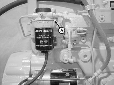
Remove and Install Final Fuel Filter/Water Bowl and/or Pre-Filter/Water Bowl Base
Refer to operator’s manual for proper servicing and (hourly) replacement intervals.
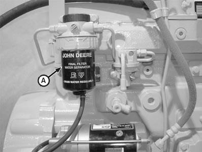
Engines are equipped with a final fuel filter/water bowl (A) and may have an optional pre-filter/water bowl.
Final fuel filters/water bowls can be equipped with a transparent (see-through) water collection bowl and/or hand primer on machines equipped with only one filter.
Electronic Fuel System Repair and Adjustments 02-090-2 CTM331 (09APR02) 4.5 L & 6.8 L Level 12 Electronic Fuel System 040902 PN=28
Continued on next page OUO1089,00001F6 –19–06NOV01–1/3 02 090 2 RG11989 –UN –15NOV01
A—Final Fuel Filter/Water Bowl Final Fuel Filter
1. Thoroughly clean fuel filter/pre-filter assemblies and surrounding area to keep from getting dirt and debris into fuel system.
2. Connect a drain line to filter drain adapters and drain all fuel from system.
NOTE: The fuel filters are keyed to the filter header. If both pre-filter and final filter are removed, ensure that they are reinstalled in the correct headers.
3. Remove final fuel filter element and pre-filter/water bowl, if desired. See REPLACE FINAL FUEL FILTER/WATER BOWL AND PRE-FILTER/WATER BOWL, in this group.
NOTE: Pre-filter and final filter fuel lines may be connected to different filter inlet and outlet ports depending on engine application. Mark fuel line location to aid during assembly. Refer to markings on fuel filter base for fuel inlet/outlet ports, as they are different between the pre- and final filter bases.
4. Disconnect fuel lines from all ports.
5. Remove final fuel filter base (A).
6. If equipped, remove pre-filter base.
7. Replace parts as necessary.
8. Install mounting brackets and tighten to torque specifications provided below.
Electronic Fuel System Repair and Adjustments 02-090-3 CTM331 (09APR02) 4.5 L & 6.8 L Level 12 Electronic Fuel System 040902 PN=29
Final Fuel Filter Base A Final Fuel Filter Base 02 090 3 Final Fuel Filter Bracket-to-Cylinder Head Specification Torque 73 N•m (54 lb-ft) Final Fuel Filter Mounting Base-to-Bracket Torque 73 N•m (54 lb-ft) Fuel Pre-Filter Bracket-to-Cylinder Head and Alternator Torque 73 N•m (54 lb-ft) Fuel Pre-Filter/Water Bowl Mounting Base-to-Bracket Torque 50 N•m (36 lb-ft) Continued on next page OUO1089,00001F6 –19–06NOV01–2/3 RG12021 –UN –26NOV01