350D and 400D Articulated
Dump Truck BELL (200311-201811) Tier2; DW (601341-608489)
REPAIR TECHNICAL MANUAL

Articulated Dump models 350D, 400D Bell-(200311—201811) DW(601341 608489)
TM1941 09 FEB 15 (ENGLISH)
For complete service information also see:
350D and 400D Articulated Dump Truck BELL (200311-201811) Tier2; DW (601341-608489) Diagnostic
Super Caddy Oil Cleanup Procedure
120 Series Hydraulic Cylinders
120 Series Hydraulic Cylinders
COOLANT HEATER SERVICE MANUAL
TM1940
CTM310
CTM120519


CTM114319
CTM10090X19
John Deere Construction and Forestry Pinted by Belgreen
FOREWORD
Table of contents
TECHNICAL INFORMATION FEEDBACK FORM
Section 00 - GENERAL INFORMATION
Group 0001 - Safety
Section 01 - WHEELS
Group 0110 - Removal and Installation
Section 02 - AXLES AND SUSPENSION SYSTEMS
Group 0200 - Removal and Installation
Group 0210 - Differential or Bevel Drive
Group 0225 - Input Drive Shafts and U-Joints
Group 0242 - Axle Mounting Parts
Group 0250 - Axle Shaft, Bearings, and Reduction Gears
Section 03 - TRANSMISSION
Group 0300 - Removal and Installation
Group 0325 - Input Drive Shafts and U-Joints
Group 0350 - Gear, Shafts, and Power Shift Clutches
Group 0360 - Hydraulic System
Section 04 - ENGINE
Group 0400 - Removal and Installation
Group 0401 - Crankshaft, Main Bearings, and Flywheel
Group 0402 - Camshaft and Timing Gear Train
Group 0403 - Cylinder Block, Liners, Pistons and Rods
Group 0407 - Lubrication System
Group 0409 - Cylinder Head and Valves
Group 0410 - Exhaust System
Group 0413 - Fuel Injection System
Group 0414 - Air Intake Manifold System
Group 0416 - Turbocharger
Group 0417 - Cooling System
Group 0418 - Thermostats, Housing and Water Piping
Section 05 - ENGINE AUXILIARY SYSTEM
Group 0510 - Cooling System
Group 0520 - Intake System
Group 0530 - External Exhaust Systems
Group 0540 - Engine Mounting
Group 0560 - External Fuel Supply Systems
Section 07 - CONNECTOR DRIVE (FLEXPLATE)
Group 0752 - Elements
Section 08 - TRANSFER DRIVE
Group 0800 - Removal and Installation
Group 0851 - Gear Shafts and Bearings
Section 09 - STEERING SYSTEM
Group 0930 - Secondary Steering
Group 0960 - Hydraulic System
Section 10 - SERVICE BRAKES
Group 1011 - Active Elements
Group 1060 - Hydraulic System
Section 11 - PARK BRAKE
Group 1111 - Active Elements
Section 17 - FRAME AND SUPPORTING STRUCTURE
Group 1740 - Frame Installation
Section 18 - OPERATOR′S STATION
TM1941-REPAIR TECHNICAL MANUAL (g) by Belgreen v2.5 <- Go to Global Table of contents TM1941-REPAIR TECHNICAL MANUAL
Group 1810 - Operator Enclosure
Group 1821 - Seat and Seat Belt
Group 1830 - Heating and Air Conditioning
Section 19 - SHEET METAL AND STYLING
Group 1910 - Hood or Engine Enclosure
Section 21 - MAIN HYDRAULIC SYSTEM
Group 2160 - Hydraulic System
Section 22 - PNEUMATIC SYSTEMS
Group 2261 - Pumps and Drives
Group 2262 - Control Valves
Group 2264 - Reservoir, Filter, and Trap
Group 2265 - Cylinders
Section 35 - HAULAGE DEVICE
Group 3540 - Frames
Group 3560 - Hydraulic System
Section 99 - DEALER FABRICATED TOOLS
Group 9900 - Dealer Fabricated Tools
TM1941-REPAIR TECHNICAL MANUAL (g) by Belgreen v2.5 <- Go to Global Table of contents TM1941-REPAIR TECHNICAL MANUAL
<- Go to Global Table of contents TM1941-REPAIR TECHNICAL MANUAL
Foreword
This manual is written for an experienced technician. Essential tools required in performing certain service work are identified in this manual and are recommended for use.
Live with safety: Read the safety messages in the introduction of this manual and the cautions presented throughout the text of the manual.
CAUTION:
This is the safety-alert symbol. When you see this symbol on the machine or in this manual, be alert to the potential for personal injury.

Technical manuals are divided in two parts: repair and operation and tests. Repair sections tell how to repair the components. Operation and tests sections help you identify the majority of routine failures quickly.
Information is organized in groups for the various components requiring service instruction. At the beginning of each group are summary listings of all applicable essential tools, service equipment and tools, other materials needed to do the job, service parts kits, specifications, wear tolerances, and torque values.
Technical Manuals are concise guides for specific machines. They are on-the-job guides containing only the vital information needed for diagnosis, analysis, testing, and repair.
Fundamental service information is available from other sources covering basic theory of operation, fundamentals of troubleshooting, general maintenance, and basic type of failures and their causes.
TM1941-REPAIR TECHNICAL MANUAL (g) by Belgreen v2.5 <- Go to Global Table of contents TM1941-REPAIR TECHNICAL MANUAL
Technical Information Feedback Form
We need your help to continually improve our technical publications. Please copy this page and FAX or mail your comments, ideas and improvements.
Technical Manual Fax
SEND TO: John Deere Dubuque Works
18600 South John Deere Road
Attn: Publications, Dept. 324 Dubuque, IA 52004-0538 USA
FAX NUMBER:
Publication Number:
Page Number:
Ideas, Comments:
1-563-589-5800 (USA)
Name:
Phone:
Email Address:
THANK YOU!
GENERAL INFORMATION (g) by Belgreen v2.0 Section 00 page 1 <- Go to Section TOC TM1941-REPAIR TECHNICAL MANUAL
TM1941-REPAIR TECHNICAL MANUAL (g) by Belgreen v2.5 <- Go to Global Table of contents TM1941-REPAIR TECHNICAL MANUAL
Table of contents Group 0001 - Safety ..................................................................................................... 1 Recognize Safety Information 1 Follow Safety Instructions Operate Only If Qualified . ......................................................................................... 1 . .......................................................................................... 1 Wear Protective Equipment .......................................................................................... 3 Avoid Unauthorized Machine Modifications......................................................................... 3 Inspect Machine ....................................................................................................... 3 Stay Clear of Moving Parts ........................................................................................... 4 Avoid High-Pressure Oils Beware of Exhaust Fumes . .......................................................................................... 4 .......................................................................................... 5 Prevent Fires ........................................................................................................... 5 Prevent Battery Explosions ........................................................................................... 6 Handle Chemical Products Safely ................................................................................... 6 Dispose of Waste Properly ........................................................................................... 6 Prepare for Emergencies............................................................................................... 7 Use Steps and Handholds Correctly ................................................................................ 7 Start Only From Operator′s Seat 8 Use and Maintain Seat Belt .......................................................................................... 8 Prevent Unintended Machine Movement ........................................................................... 8 Avoid Work Site Hazards Keep Riders Off Machine Avoid Backover Accidents . .......................................................................................... 9 . .......................................................................................... 9 .........................................................................................10 Avoid Machine Tip Over..............................................................................................10 Operating on Slopes..................................................................................................11 Operating Or Traveling On Public Roads...........................................................................12 Inspect and Maintain ROPS ..........................................................................................12 Add and Operate Attachments Safely Park And Prepare For Service Safely ...........................................................................12 . ...........................................................................12 Service Tires Safely...................................................................................................14 Service Cooling System Safely 14 Remove Paint Before Welding or Heating.........................................................................15 Make Welding Repairs Safely .......................................................................................15 Drive Metal Pins Safely ..............................................................................................16
Section 00 - GENERAL INFORMATION
Group 0001 - Safety Recognize Safety Information
Safety Alert Symbols
Safety Alert Symbols
This is the safety alert symbol. When this symbol is noticed on the machine or in this manual, be alert for the potential of personal injury.

Follow the precautions and safe operating practices highlighted by this symbol.
A signal word DANGER, WARNING, or CAUTION is used with the safety alert symbol. DANGER identifies the most serious hazards.

On the machine, DANGER signs are red in color, WARNING signs are orange, and CAUTION signs are yellow. DANGER and WARNING signs are located near specific hazards. General precautions are on CAUTION labels.
Follow Safety Instructions
Follow Safety Instructions
Read the safety messages in this manual and on the machine. Follow these warnings and instructions carefully. Review them frequently.
Be sure all operators of this machine understand every safety message. Replace operator′s manual and safety labels immediately if missing or damaged.
Operate Only If Qualified
Do not operate this machine unless the operator′s manual has been read carefully, and you have been qualified by supervised
Section 00 - GENERAL INFORMATION Group 0001: Safety Section 00 page 1 <- Go to Section TOC TM1941-REPAIR TECHNICAL MANUAL
Operator should be familiar with the job site and surroundings before operating. Try all controls and machine functions with the machine in an open area before starting to work.
Know and observe all safety rules that may apply to every work situation and work site.
Section 00 - GENERAL INFORMATION Group 0001: Safety Section 00 page 2 <- Go to Section TOC TM1941-REPAIR TECHNICAL MANUAL training and
instruction.
Protective Equipment
Guard against injury from flying pieces of metal or debris; wear goggles or safety glasses. Wear close fitting clothing and safety equipment appropriate to the job.
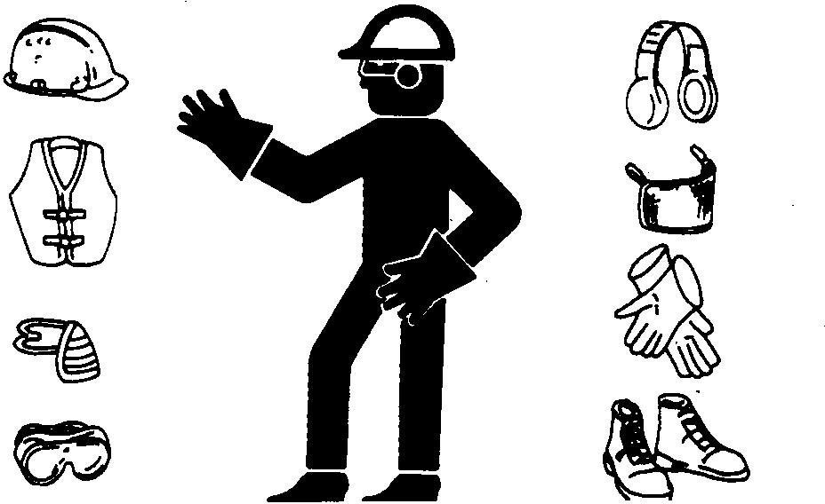
Prolonged exposure to loud noise can cause impairment or loss of hearing. Wear suitable hearing protection such as earmuffs or earplugs to protect against objectionable or uncomfortable loud noises.
Avoid Unauthorized Machine Modifications
Modifications of this machine, or addition of unapproved products or attachments, may affect machine stability or reliability, and may create a hazard for the operator or others near the machine.
Always contact an authorized dealer before making machine modifications that change the intended use, weight or balance of the machine, or that alter machine controls, performance or reliability.
Inspect Machine
Inspect Machine
Section 00 - GENERAL INFORMATION Group 0001: Safety Section 00 page 3 <- Go to Section TOC TM1941-REPAIR TECHNICAL MANUAL
Wear Protective Equipment
Inspect machine carefully each day by walking around it before starting. Inspect and Clean the Polycarbonate Windows. See Inspect and Clean Polycarbonate Windows. (Section 4-1.)
Keep all guards and shields in good condition and properly installed. Fix damage and replace worn or broken parts immediately. Pay special attention to hydraulic hoses and electrical wiring.
Stay Clear of Moving Parts
Stay Clear Of Moving Parts
Entanglements in moving parts can cause serious injury.
Stop engine before examining, adjusting or maintaining any part of machine with moving parts. Keep guards and shields in place. Replace any guard or shield that has been removed for access as soon as service or repair is complete.
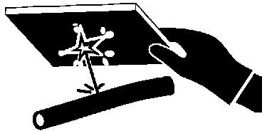
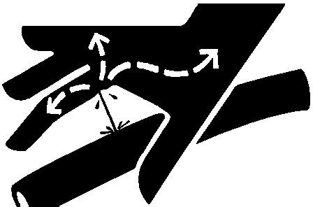
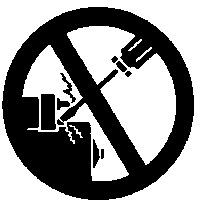
Avoid High-Pressure Oils
Avoid High Pressure Oils
Avoid High-Pressure Oils
This machine uses a high-pressure hydraulic system. Escaping oil under pressure can penetrate the skin causing serious injury. Never search for leaks with your hands. Protect hands. Use a piece of cardboard to find location of escaping oil. Stop engine and relieve pressure before disconnecting lines or working on hydraulic system.
If hydraulic oil penetrates your skin, see a doctor immediately. Injected oil must be removed surgically within hours or gangrene may result. Contact a knowledgeable medical source or the Deere & Company Medical Department in
Section 00 - GENERAL INFORMATION Group 0001: Safety Section 00 page 4 <- Go to Section TOC TM1941-REPAIR TECHNICAL MANUAL
Beware of Exhaust Fumes
Beware Of Exhaust Fumes
Prevent asphyxiation. Engine exhaust fumes can cause sickness or death. If you must operate in an enclosed space, provide adequate ventilation. Use an exhaust pipe extension to remove the exhaust fumes or open doors and windows to bring outside air into the area.
Prevent Fires
Handle Fuel Safely
Clean Machine Regularly
Carry A Fire Extinguisher
Handle Fuel Safely: Store flammable fluids away from fire hazards. Never refuel machine while smoking or when near sparks or flame.

Clean Machine Regularly: Keep trash, debris, grease and oil from accumulating in engine compartment, around fuel lines, hydraulic lines, exhaust components, and electrical wiring. Never store oily rags or flammable materials inside a machine
Section 00 - GENERAL INFORMATION Group 0001: Safety Section 00 page 5 <- Go to Section TOC TM1941-REPAIR TECHNICAL MANUAL Moline, Illinois, U.S.A.
compartment.
Maintain Hoses and Wiring: Replace hydraulic hoses immediately if they begin to leak, and clean up any oil spills. Examine electrical wiring and connectors frequently for damage.
Keep A Fire Extinguisher Available: Always keep a multipurpose fire extinguisher on or near the machine. Know how to use extinguisher properly.
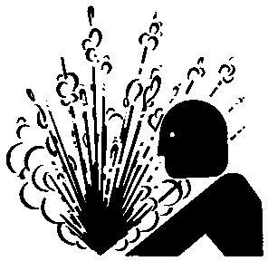
Prevent Battery Explosions
Battery Explosions
Battery gas can explode. Keep sparks, lighted matches, and open flame away from the top of battery. Never check battery charge by placing a metal object across the posts. Use a voltmeter or hydrometer. Do not charge a frozen battery; it may explode. Warm battery to 16°C (60°F).
Handle Chemical Products Safely
Handle Chemical Products Safely
Exposure to hazardous chemicals can cause serious injury. Under certain conditions, lubricants, coolants, paints and adhesives used with this machine may be hazardous.
If uncertain about safe handling or use of these chemical products, contact your authorized dealer for a Material Safety Data Sheet (MSDS). The MSDS describes physical and health hazards, safe use procedures, and emergency response techniques for chemical substances. Follow MSDS recommendations to handle chemical products safely.
Dispose of Waste Properly
Section 00 - GENERAL INFORMATION Group 0001: Safety Section 00 page 6 <- Go to Section TOC TM1941-REPAIR TECHNICAL MANUAL
Dispose Of Waste Properly

Improper disposal of waste can threaten the environment. Fuel, oils, coolants, filters and batteries used with this machine may be harmful if not disposed of properly.
Never pour waste onto the ground, down a drain, or into any water source.
Air conditioning refrigerants can damage the atmosphere. Government regulations may require using a certified service center to recover and recycle used refrigerants.
If uncertain about the safe disposal of waste, contact your local environmental or recycling center or your dealer for more information.
Prepare for Emergencies
First Aid Kit
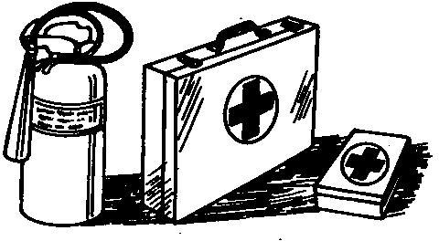
Be prepared if an emergency occurs or a fire starts. Keep a first aid kit and fire extinguisher handy. Keep emergency numbers for doctors, ambulance service, hospital, and fire department near your telephone.
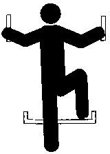
Use Steps and Handholds Correctly
Use Handholds and Steps
Prevent falls by facing the machine when getting on and off. Maintain 3-point contact with steps and handrails. Never use machine controls as handholds.
Section 00 - GENERAL INFORMATION Group 0001: Safety Section 00 page 7 <- Go to Section TOC TM1941-REPAIR TECHNICAL MANUAL
Use extra care when mud, snow, or moisture present slippery conditions. Keep steps clean and free of grease or oil. Never jump when exiting machine. Never mount or dismount a moving machine.
Start Only From Operator′s Seat
Operate Only From Operators Seat
Avoid unexpected machine movement. Start engine only while sitting in operator′s seat. Ensure all controls and working tools are in proper position for a parked machine.
Never attempt to start engine from the ground. Do not attempt to start engine by shorting across the starter solenoid terminals.
Use and Maintain Seat Belt
Use and Maintain Seat Belt
Use seat belt when operating machine . Remember to fasten seat belt when loading and unloading from trucks and during other uses.
Examine seat belt frequently. Be sure webbing is not cut or torn. Replace seat belt immediately if any part is damaged or does not function properly.
The complete seat belt assembly should be replaced every 3 years, regardless of appearance.
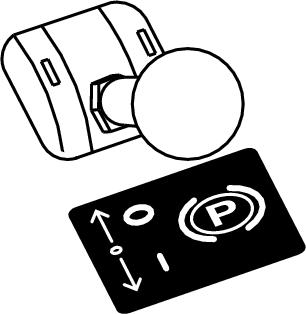
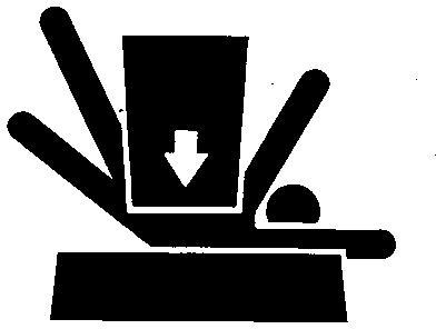
Prevent Unintended Machine Movement
Section 00 - GENERAL INFORMATION Group 0001: Safety Section 00 page 8 <- Go to Section TOC TM1941-REPAIR TECHNICAL MANUAL
Park Brake Control
Be careful not to accidentally actuate controls when co-workers are present.
Ensure dump body is lowered during work interruptions. Place transmission control in neutral, engage park brake and stop engine before allowing anyone to approach the machine.
Follow these same precautions before standing up, leaving the operator′s seat, or exiting the machine.
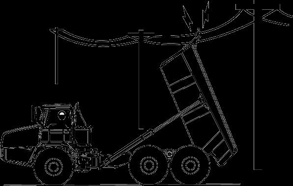
Avoid Work Site Hazards
Work Site Hazards
Work Site Hazards
Prepare work site properly . Avoid operating near structures or objects that could fall onto the machine. Clear away debris that could move unexpectedly if run over.
Avoid contact with overhead obstacles or overhead electrical lines. Never move any part of machine or load closer than 3 m (10 ft) plus twice the line insulator length to overhead wires.
Keep bystanders clear at all times. Use barricades or a signal person to keep vehicles and pedestrians away. Use a signal person if moving machine in congested areas or where visibility is restricted. Always keep signal person in view. Coordinate hand signals before starting machine.
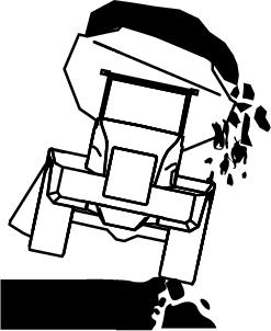
Operate only on solid footing with strength sufficient to support machine. Be especially alert working near embankments or excavations, or when dump body is in raised position.
Avoid working on stockpiles that could collapse under machine. Use caution when backing up to berms.
Section 00 - GENERAL INFORMATION Group 0001: Safety Section 00 page 9 <- Go to Section TOC TM1941-REPAIR TECHNICAL MANUAL
Keep Riders Off Machine
Keep Riders Off Machine
Use seat belt at all times.
Only allow operator on machine except when necessary for instruction or short periods of observation. Riders are subject to injury. They may fall from machine, be caught between machine parts, or be struck by foreign objects. They also may obstruct operator’s view or impair his ability to operate machine safely.
Use the instructional seat only to accommodate trainers or persons needing to observe machine operation for short periods.
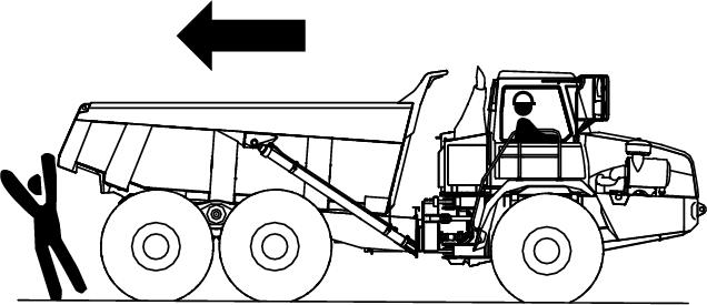
Avoid Backover Accidents
Backover Warning
Before moving machine, be sure all persons are clear of machine path. Where conditions permit, raise dump body for better visibility to the rear. Use mirrors to assist in checking all around machine. Keep windows and mirrors clean, adjusted, and in good repair.
Be certain backup alarm is working properly.
Use a signal person when backing if view is obstructed or when in close quarters. Keep signal person in view at all times. Use prearranged hand signals to communicate.
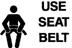
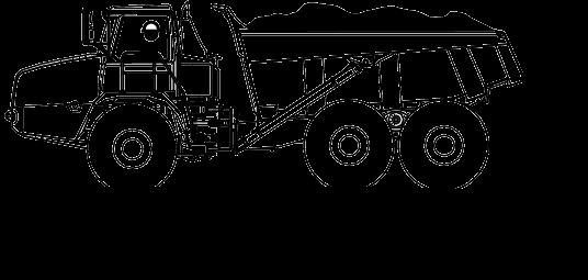
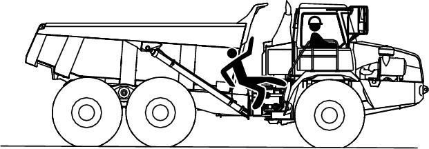
Avoid Machine Tip Over
Section 00 - GENERAL INFORMATION Group 0001: Safety Section 00 page 10 <- Go to Section TOC TM1941-REPAIR TECHNICAL MANUAL
Use Seat Belt
Avoid Machine Tip Over
Use seat belt at all times. Do not jump if the machine tips. You will be unlikely to jump clear and the machine may crush you.
Use extra care when dump body is raised. Machine stability is greatly reduced when dump body is raised. Drive slowly. Avoid sharp turns and uneven ground.
Be careful on slopes and soft, rocky, or frozen ground. Traction and stability are reduced by slopes and adverse terrain. Avoid piles of dirt and banks or excavations that may cave in and cause the machine to tip or fall.
Do not overload the machine. Oversize loads reduce machine stability, increase tire flex, and erode travel surfaces. Braking capability and brake life are also reduced.
If machine tips, carefully inspect brake and hydraulic lines, electrical wiring, and machine structure before operating.
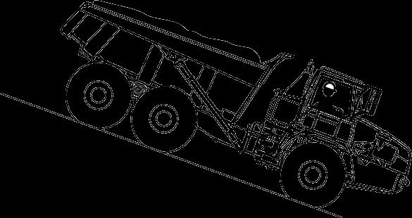
Operating on Slopes
Operating on Slopes
Avoid sideslope travel whenever possible.
Section 00 - GENERAL INFORMATION Group 0001: Safety Section 00 page 11 <- Go to Section TOC TM1941-REPAIR TECHNICAL MANUAL
Check service brake condition frequently when operating on slopes.
Select low gear speed before starting down slope. The maximum slope you can operate on will be limited by ground conditions and load being handled.
Use transmission retarder (if equipped) or exhaust brake and service brakes, to control speed. Sudden brake application with a loaded dump body could cause loss of machine control.
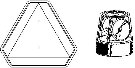
Operating Or Traveling On Public Roads
Operating or Traveling On Public Roads
Machines that work near vehicle traffic or travel slower than normal highway speeds must have proper lighting and markings to assure they are visible to other drivers. Mirrors are especially important for the operator when on roadways. Install additional lights, beacons, slow moving vehicle (SMV) emblems, or other devices and use as required to make the machine visible and identify it as a work machine. Check state and local regulations to assure compliance. Keep these devices clean and in working condition.
Inspect and Maintain ROPS
A damaged roll-over protective structure (ROPS) should be replaced, not reused. The protection offered by ROPS will be impaired if ROPS is subjected to structural damage, is involved in an overturn incident, or is in any way altered by welding, bending, drilling, or cutting.
If ROPS was loosened or removed for any reason, inspect it carefully before operating the machine again.
To maintain the ROPS:
Replace missing hardware using correct grade hardware.
Check hardware torque.
Check isolation mounts for damage, looseness or wear; replace them if necessary.
Check ROPS for cracks or physical damage.
Add and Operate Attachments Safely
Always verify compatibility of attachments by contacting your authorized dealer. Adding unapproved attachments may affect machine stability or reliability, and may create a hazard for others near the machine. Ensure that a qualified person is involved in attachment installation. Add guards to machine if operator protection is required or recommended. Verify that all connections are secure and attachment responds properly to controls. Carefully read attachment manual and follow all instructions and warnings. In an area free of bystanders and obstructions, carefully operate attachment to learn its characteristics and range of motion.
Park And Prepare For Service Safely
Section 00 - GENERAL INFORMATION Group 0001: Safety Section 00 page 12 <- Go to Section TOC TM1941-REPAIR TECHNICAL MANUAL
Do Not Operate Tag
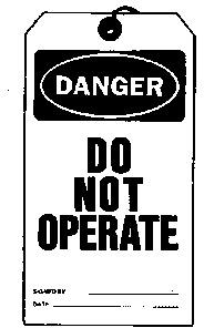
Support Machine Properly
Warn others of service work. Always park and prepare your machine for service or repair properly.
Park machine on a level surface.
Lower dump body unless raised position is required for service.
Engage park brake.
Stop engine and remove key.
Attach a “Do Not Operate” tag in an obvious place in the operator′s station. Install the articulation safety locking bar. Install service locks if dump body or cab are raised for service.
Securely support machine before working under it.
Install wheel chocks to ensure machine cannot move backward or forward during service.
Understand service procedures before beginning repairs. Keep service area clean and dry. Use two people whenever the engine must be running for service work.
Section 00 - GENERAL INFORMATION Group 0001: Safety Section 00 page 13 <- Go to Section TOC TM1941-REPAIR TECHNICAL MANUAL
Explosive Tire and Rim Parts
Explosive separation of a tire and rim parts can cause serious injury or death.
Do not attempt to mount a tire unless you have the proper equipment and experience to perform the job.
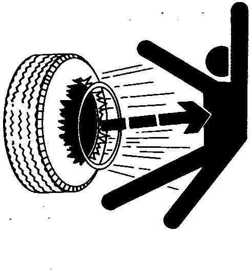
Always maintain the correct tire pressure. Do not inflate the tires above the recommended pressure. Never weld or heat a wheel and tire assembly. The heat can cause an increase in air pressure resulting in a tire explosion. Welding can structurally weaken or deform the wheel.
When inflating tires, use a clip-on chuck and extension hose long enough to allow you to stand to one side and NOT in front of or over the tire assembly. Use a safety cage if available. Check wheels for low pressure, cuts, bubbles, damaged rims or missing lug bolts and nuts.
Service Cooling System Safely
Section 00 - GENERAL INFORMATION Group 0001: Safety Section 00 page 14 <- Go to Section TOC TM1941-REPAIR TECHNICAL MANUAL Service Tires Safely
Cooling System
Explosive release of fluids from pressurized cooling system can cause serious burns. Shut off engine. Only remove filler cap when cool enough to touch with bare hands. Slowly loosen cap to first stop to relieve pressure before removing completely.
Remove Paint Before Welding or Heating
Toxic Fumes
Hazardous fumes can be generated when paint is heated by welding or using a torch. Dust from sanding or grinding paint can also be hazardous.
Remove paint to at least 76 mm (3 in.) from area to be heated. Wear an approved respirator when sanding or grinding paint. If a solvent or paint stripper is used, wash area with soap and water. Remove solvent or paint stripper containers from work area, and allow fumes to disperse at least 15 minutes before welding or heating.
Work outside or in a well-ventilated area. Dispose of waste, paint, and solvents properly.
Make Welding Repairs Safely
Avoid Heating Near Pressurized Fluid Lines
Section 00 - GENERAL INFORMATION Group 0001: Safety Section 00 page 15 <- Go to Section TOC TM1941-REPAIR TECHNICAL MANUAL
IMPORTANT:
Disable electrical power before welding. Turn off main battery switch or disconnect positive battery cable. Separate harness connectors to engine and vehicle microprocessors.
Avoid welding or heating near pressurized fluid lines. Flammable spray may result and cause severe burns if pressurized lines fail as a result of heating. Do not let heat go beyond work area to nearby pressurized lines. Remove paint properly. Do not inhale paint dust or fumes. Use a qualified welding technician for structural repairs. Make sure there is good ventilation. Wear eye protection and protective equipment when welding.
Drive Metal Pins Safely
Hardened Metal Parts
Always wear protective goggles or safety glasses and other protective equipment before striking hardened parts. Hammering hardened metal parts such as pins and bucket teeth may dislodge chips at high velocity. Use a soft hammer or a brass bar between hammer and object to prevent chipping.
WHEELS (g) by Belgreen v2.0 Section 01 page 16 <- Go to Section TOC TM1941-REPAIR TECHNICAL MANUAL
TM1941-REPAIR TECHNICAL MANUAL (g) by Belgreen v2.5 <- Go to Global Table of contents TM1941-REPAIR TECHNICAL MANUAL Section 01 - WHEELS Table of contents Group 0110 - Removal and Installation ............................................................................ 1 Remove and Install Wheel 1 Remove and Install Tire .............................................................................................. 3
Group 0110 - Removal and Installation
Remove and Install Wheel
CAUTION:
Always chock at least one other wheel when raising a wheel off the ground.
Park the machine on firm level ground. Chock wheels.
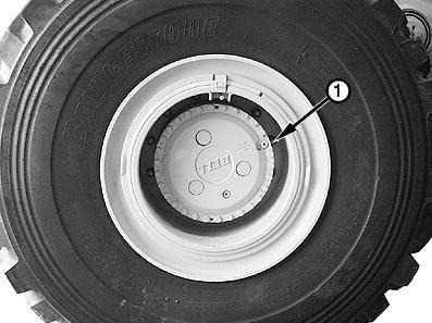
[2] -
Flange Nuts
Loosen flange nuts (1) one full turn.
[3] -
CAUTION:
Components are heavy. Use lifting devices.
LEGEND: 1 Flange Nut and Washer (12 used)
Section 01 - WHEELS Group 0110: Removal and Installation Section 01 page 1 <- Go to Section TOC TM1941-REPAIR TECHNICAL MANUAL
[1] -
Item Remove and Install Wheel Measurement Specification 350D Articulated Dump Truck Weight 26 725 kg (58,919 lb) 400D Articulated Dump Truck Weight 28 850 kg (63,603 lb) Tire and Rim Weight 771 kg (1700 lb) approximate
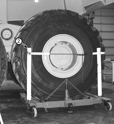
Raise wheel. Support axle housing with an 18-t (20 ton) floor stand.
[4] -
LEGEND: 2 Wheel Lift
Wheel Jack
Attach wheel lift (2) to wheel. Secure tire with safety chain.
[5] - Remove flange nuts and washers. Remove wheel.
[6] - Clean threads of wheel bolts and flange nuts. Clean mating surfaces of flange nuts, washers, rim, and hub.
[7] -
IMPORTANT:
Re-check torque on flange nuts after five hours. Tighten as necessary. Re-check torque every 50 hours thereafter.
IMPORTANT:
Check tire diameter before installing wheel. Difference in tire diameter must be within 2% across axles and between axles. Excessive differences in tire rollout will cause drivetrain malfunctions.
Install wheel. Install washers and flange nuts. Tighten flange nuts to specification in a crisscross pattern.
and Install Wheel
Section 01 - WHEELS Group 0110: Removal and Installation Section 01 page 2 <- Go to Section TOC TM1941-REPAIR TECHNICAL MANUAL
Item Remove
Measurement Specification Flange Nut Torque 650 N˙m (480 lb-ft)
Remove and Install Tire
CAUTION:
Service Tires Safely . (See Group 0001.)
→NOTE:
Tire can be removed without removing wheel from machine.
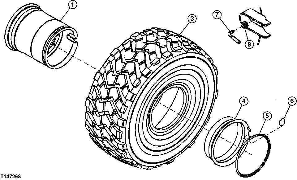
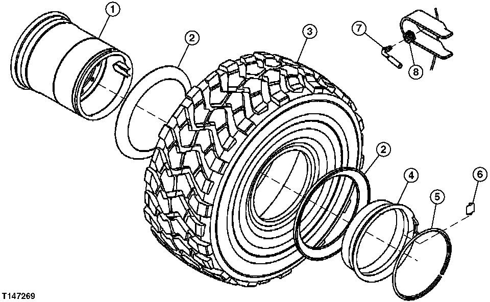
Section 01 - WHEELS Group 0110: Removal and Installation Section 01 page 3 <- Go to Section TOC TM1941-REPAIR TECHNICAL MANUAL [1] -
3-Piece Rim
5-Piece Rim
2 Side Ring (2 used) 5-Piece Rims Only
Remove valve core from valve stem (7) to deflate tire (3). Check valve stem for plugging by inserting a probe.
[2] - Inspect and replace parts as necessary.
[3] -
IMPORTANT:
To prevent slippage between tire and rim during machine operation, clean all contact surfaces thoroughly before assembly.
Thoroughly clean all parts before assembly.
[4] - Apply soap lubricant to beads of tire (3). Assemble wheel set (1 6). Ensure that all components are properly aligned and seated.
[5] - Install valve stem (7). Hand-tighten seal nut (8).
[6] - Install pressure-regulating valve, clip-on chuck, and extension hose on valve stem.
[7] -
CAUTION:
Clear area of all persons. Stand aside while inflating tire. DO NOT stand in front of tire. Use only recommended air pressure. Pressure over this limit can cause explosion.
Section 01 - WHEELS Group 0110: Removal and Installation Section 01 page 4 <- Go to Section TOC TM1941-REPAIR TECHNICAL MANUAL
LEGEND: 1 Rim
3 Tire 4 Bead
Ring 5 Lock Ring 6 Driver Block 7 Valve Stem 8 Seal Nut
Seat
Add air until tire beads slide out against seats.
[8] - Re-check proper alignment of wheel set components around entire circumference before fully inflating tire.
[9] - Inflate tire to specification. Check air pressure in tire using an accurate gauge with 7 kPa (0.07 bar) (1 psi) graduations.
See Inspect Tires, Check Pressure (Operator′s Manual, Section 3-3).
Tire Pressure Gauge With 7 kPa (0.07 bar) (1 psi) Graduations
Inflate tires to specification.
AXLES AND SUSPENSION SYSTEMS (g) by Belgreen v2.0 Section 02 page 5 <- Go to Section TOC TM1941-REPAIR TECHNICAL MANUAL
Section 02 - AXLES AND SUSPENSION SYSTEMS
<- Go to Global Table of contents TM1941-REPAIR TECHNICAL MANUAL
Table of contents Group 0200 - Removal and Installation ............................................................................ 1 Axles..................................................................................................................... 1 Group 0210 - Differential or Bevel Drive........................................................................... 5 Axle Differential ....................................................................................................... 5 Group 0225 - Input Drive Shafts and U-Joints...................................................................26 Drive Shafts ...........................................................................................................26 Group 0242 - Axle Mounting Parts .................................................................................35 Axle Links, Stabilizers, and Struts Remove and Install 35 Recharge Front Suspension Strut ..................................................................................39 Front Suspension Strut Disassemble and Assemble .............................................................45 Replace Links and Stabilizer Bushings .............................................................................52 Front Axle Pivot.......................................................................................................54 Middle and Rear Axle Walking Beams..............................................................................56 Group 0250 - Axle Shaft, Bearings, and Reduction Gears ...................................................63 Axle Outboard Planetaries ..........................................................................................63 Axle Shafts Axle Hubs . .........................................................................................................66 67 TM1941-REPAIR TECHNICAL MANUAL (g) by Belgreen v2.5