
OPERATION & TEST TECHNICAL MANUAL

Foreword
This manual is written for an experienced technician. Essential tools required in performing certain service work are identified in this manual and are recommended for use. Live with safety: Read the safety messages in the introduction of this manual and the cautions presented throughout the text of the manual.
This is the safety-alert symbol. When you see this symbol on the machine or in this manual, be alert to the potential for personal injury.

Technical manuals are divided in two parts: repair and operation and tests. Repair sections tell how to repair the components. Operation and tests sections help you identify the majority of routine failures quickly.
Information is organized in groups for the various components requiring service instruction. At the beginning of each group are summary listings of all applicable essential tools, service equipment and tools, other materials needed to do the job, service parts kits, specifications, wear tolerances, and torque values.
Technical Manuals are concise guides for specific machines. They are on-the-job guides containing only the vital information needed for diagnosis, analysis, testing, and repair.
Fundamental service information is available from other sources covering basic theory of operation, fundamentals of troubleshooting, general maintenance, and basic type of failures and their causes.
Technical Information Feedback Form
We need your help to continually improve our technical publications. Please copy this page and FAX or mail your comments, ideas and improvements.
SEND TO: John Deere Dubuque Works
18600 South John Deere Road
Attn: Publications, Dept. 324
Dubuque, IA 52004-0538 USA
FAX NUMBER: 1-563-589-5800 (USA)
Publication Number:
Page Number:
Ideas, Comments:
Name:
Phone:
Email Address:
THANK YOU!
TM11398 (28MAY15)
318D and 320D (Manual Controls)
Section 9000—General Information
Group 01 Safety
Section 9001 Diagnostic Trouble Codes (DTCs)
Group 10 Engine Control Unit (ECU) Diagnostic Trouble Codes
Group 20 Engagement and Monitor Unit (EMU) Diagnostic Trouble Codes
Section 9005—Operational Checkout Procedure
Group 10 Operational Checkout Procedure
Section 9010—Engine
Group 05 Theory of Operation
Group 15 Diagnostic Information
Group 25 Tests
Section 9015 Electrical System
Group 05 System Information
Group 10 System Diagrams
Group 15 Sub-System Diagnostics
Group 16 Monitor Operation Group 20 References
Section 9020—Power Train
Group 05 Theory of Operation
Group 15 Diagnostic Information
Group 25 Tests
Section 9025—Hydraulic System
Group 05 Theory of Operation
Group 15 Diagnostic Information
Group 25 Tests
Section 9026—Hydrostatic System
Group 05 Theory of Operation
Group 15 Diagnostic Information
Group 25 Tests
Section 9031—Heating and Air Conditioning
Group 05 Theory of Operation
Group 15 Diagnostic Information
Group 25 Tests
Section 9900—Dealer Fabricated Tools
Group 99 Dealer Fabricated Tools
Original Instructions. All information, illustrations and specifications in this manual are based on the latest information available at the time of publication. The right is reserved to make changes at any time without notice.
Recognize Safety Information
This is the safety alert symbol. When this symbol is noticed on the machine or in this manual, be alert for the potential of personal injury.

Follow the precautions and safe operating practices highlighted by this symbol.
A signal word DANGER, WARNING, or CAUTION is used with the safety alert symbol. DANGER identifies the most serious hazards.
On the machine, DANGER signs are red in color, WARNING signs are orange, and CAUTION signs are yellow. DANGER and WARNING signs are located near specific hazards. General precautions are on CAUTION labels.

Follow Safety Instructions
Carefully read all safety messages in this manual and on your machine safety signs. Keep safety signs in good condition. Replace missing or damaged safety signs. Be sure new equipment components and repair parts include the current safety signs. Replacement safety signs are available from your John Deere dealer.
There can be additional safety information contained on parts and components sourced from suppliers that is not reproduced in this operator's manual.
Learn how to operate the machine and how to use controls properly. Do not let anyone operate without instruction.

Keep your machine in proper working condition. Unauthorized modifications to the machine may impair the function and/or safety and affect machine life.
Operate Only If Qualified
If you do not understand any part of this manual and need assistance, contact your John Deere dealer.
Do not operate this machine unless the operator's manual machine functions with the machine in an open area has been read carefully, and you have been qualified by before starting to work. supervised training and instruction.
Know and observe all safety rules that may apply to every Operator should be familiar with the job site and work situation and work site. surroundings before operating. Try all controls and
Wear Protective Clothing
Wear close fitting clothing and safety equipment appropriate to the job.

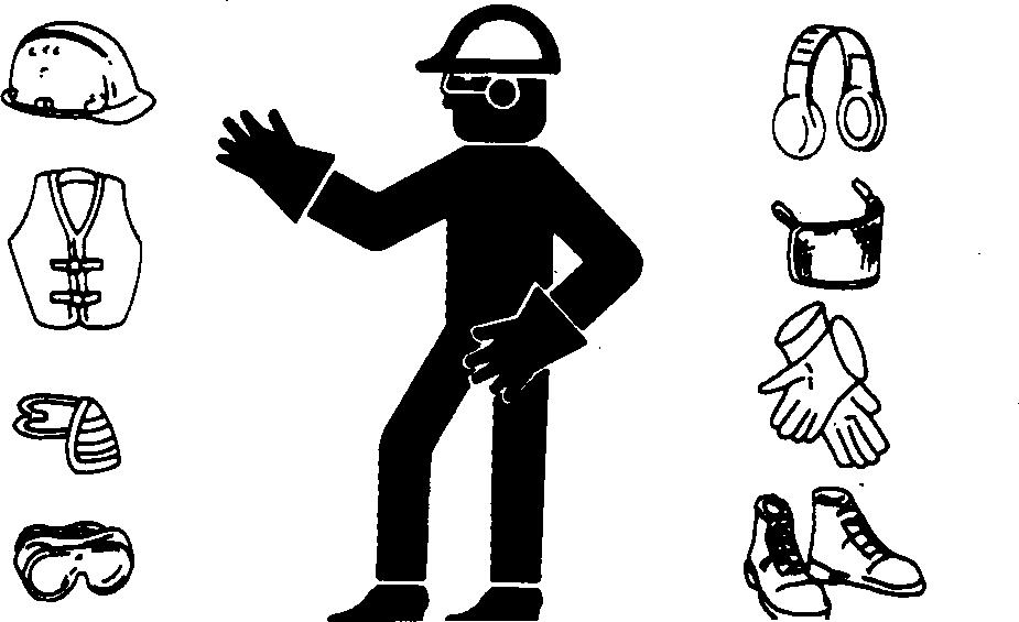
Prolonged exposure to loud noise can cause impairment or loss of hearing.
Wear a suitable hearing protective device such as earmuffs or earplugs to protect against objectionable or uncomfortable loud noises.
Operating equipment safely requires the full attention of the operator. Do not wear radio or music headphones while operating machine.
Avoid Unauthorized Machine Modifications
John Deere recommends using only genuine John Deere replacement parts to ensure machine performance. Never substitute genuine John Deere parts with alternate parts not intended for the application as these can create hazardous situations or hazardous performance. Non-John Deere parts, or any damage or failures resulting from their use are not covered by any John Deere warranty.
Modifications of this machine, or addition of unapproved products or attachments, may affect machine stability or
Inspect Machine
Inspect machine carefully each day by walking around it before starting.
Inspect and Clean the Polycarbonate Windows. See Inspect and Clean Polycarbonate Windows. (Section 4-1.)
Keep all guards and shields in good condition and properly installed. Fix damage and replace worn or broken parts immediately. Pay special attention to hydraulic hoses and electrical wiring.
reliability, and may create a hazard for the operator or others near the machine. The installer of any modification which may affect the electronic controls of this machine is responsible for establishing that the modification does not adversely affect the machine or its performance.
Always contact an authorized dealer before making machine modifications that change the intended use, weight or balance of the machine, or that alter machine controls, performance or reliability.
Stay Clear of Moving Parts
Entanglements in moving parts can cause serious injury. Stop engine before examining, adjusting or maintaining any part of machine with moving parts.
Keep guards and shields in place. Replace any guard or shield that has been removed for access as soon as service or repair is complete.
Avoid High-Pressure Fluids
Inspect hydraulic hoses periodically – at least once per year – for leakage, kinking, cuts, cracks, abrasion, blisters, corrosion, exposed wire braid or any other signs of wear or damage.
Replace worn or damaged hose assemblies immediately with John Deere approved replacement parts.
Escaping fluid under pressure can penetrate the skin causing serious injury.
Avoid the hazard by relieving pressure before disconnecting hydraulic or other lines. Tighten all connections before applying pressure.
with this type of injury should reference a knowledgeable Search for leaks with a piece of cardboard. Protect hands medical source. Such information is available in and body from high-pressure fluids. English from Deere & Company Medical Department in If an accident occurs, see a doctor immediately. Any fluid Moline, Illinois, U.S.A., by calling 1-800-822-8262 or +1 injected into the skin must be surgically removed within 309-748-5636. a few hours or gangrene may result. Doctors unfamiliar
Avoid High-Pressure Oils

This machine uses a high-pressure hydraulic system. Escaping oil under pressure can penetrate the skin causing serious injury.
Never search for leaks with your hands. Protect hands. Use a piece of cardboard to find location of escaping oil. Stop engine and relieve pressure before disconnecting lines or working on hydraulic system.
If hydraulic oil penetrates your skin, see a doctor immediately. Injected oil must be removed surgically within hours or gangrene may result. Contact a knowledgeable medical source or the Deere & Company Medical Department in Moline, Illinois, U.S.A.

Work In Ventilated Area
Engine exhaust fumes can cause sickness or death. If it is necessary to run an engine in an enclosed area, remove the exhaust fumes from the area with an exhaust pipe extension.
If you do not have an exhaust pipe extension, open the doors and get outside air into the area.
Prevent Fires

Handle Fuel Safely: Store flammable fluids away from fire hazards. Never refuel machine while smoking or when near sparks or flame.

Clean Machine Regularly: Keep trash, debris, grease and oil from accumulating in engine compartment, around fuel lines, hydraulic lines, exhaust components, and electrical wiring. Never store oily rags or flammable materials inside a machine compartment.

Maintain Hoses and Wiring: Replace hydraulic hoses immediately if they begin to leak, and clean up any oil spills. Examine electrical wiring and connectors frequently for damage.
Keep A Fire Extinguisher Available: Always keep a multipurpose fire extinguisher on or near the machine Know how to use extinguisher properly.

Prevent Battery Explosions
Keep sparks, lighted matches, and open flame away from the top of battery. Battery gas can explode.
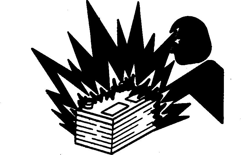
Never check battery charge by placing a metal object across the posts. Use a volt-meter or hydrometer.
Do not charge a frozen battery; it may explode. Warm battery to 16°C (60°F).
Handle Chemical Products Safely
Direct exposure to hazardous chemicals can cause serious injury. Potentially hazardous chemicals used with John Deere equipment include such items as lubricants, coolants, paints, and adhesives.
A Material Safety Data Sheet (MSDS) provides specific details on chemical products: physical and health hazards, safety procedures, and emergency response techniques.
Check the MSDS before you start any job using a hazardous chemical. That way you will know exactly what the risks are and how to do the job safely. Then follow procedures and recommended equipment.

(See your John Deere dealer for MSDS’s on chemical products used with John Deere equipment.)
Dispose of Waste Properly
Improperly disposing of waste can threaten the environment and ecology. Potentially harmful waste used with John Deere equipment include such items as oil, fuel, coolant, brake fluid, filters, and batteries.
Use leakproof containers when draining fluids. Do not use food or beverage containers that may mislead someone into drinking from them.
Do not pour waste onto the ground, down a drain, or into any water source.
Air conditioning refrigerants escaping into the air can damage the Earth’s atmosphere. Government regulations may require a certified air conditioning service center to recover and recycle used air conditioning refrigerants.
Inquire on the proper way to recycle or dispose of waste from your local environmental or recycling center, or from your John Deere dealer.

Prepare for Emergencies
Be prepared if an emergency occurs or a fire starts. Keep a first aid kit and fire extinguisher handy. Keep emergency numbers for doctors, ambulance service, hospital, and fire department near your telephone.

Clean Debris from Machine
Keep engine compartment, radiator, batteries, hydraulic lines, exhaust components, fuel tank, and operator's station clean and free of debris.
Clean any oil spills or fuel spills on machine surfaces. Temperature in engine compartment may go up immediately after engine is stopped. BE ON GUARD FOR FIRES DURING THIS PERIOD.
Open access door(s) to cool the engine faster, and clean engine compartment.
Use Steps and Handholds Correctly
Prevent falls by facing the machine when getting on and off. Maintain 3-point contact with steps and handrails. Never use machine controls as handholds.

Use extra care when mud, snow, or moisture present slippery conditions. Keep steps clean and free of grease or oil. Never jump when exiting machine. Never mount or dismount a moving machine.
Start Only From Operator's Seat
Avoid unexpected machine movement. Start engine only while sitting in operator's seat. Ensure all controls and working tools are in proper position for a parked machine. Never attempt to start engine from the ground. Do not attempt to start engine by shorting across the starter solenoid terminals.

Use and Maintain Seat Belt

Use seat belt when operating machine Remember to fasten seat belt when loading and unloading from trucks and during other uses.
Examine seat belt frequently. Be sure webbing is not cut or torn. Replace seat belt immediately if any part is damaged or does not function properly.
The complete seat belt assembly should be replaced every 3 years, regardless of appearance.
Prevent Unintended Machine Movement
Be careful not to accidentally actuate controls. Follow these steps during work interruptions, before allowing coworkers to approach the machine, before standing up, leaving the operator's seat, or exiting the machine:
• Lower equipment to the ground
• Press park brake switch (1) to position P to engage park brake

• Stop the engine
• Raise interlocking seat bar
Avoid Work Site Hazards
Avoid contact with gas lines, buried cables, and water lines. Call utility line location services to identify all underground utilities before starting work. Prepare work site properly. Avoid operating near structures or objects that could fall onto the machine. Clear away debris that could move unexpectedly if run over.
Avoid boom or attachment contact with overhead obstacles or overhead electrical lines. Never move machine closer than 3 m (10 ft.) plus twice the line insulator length to overhead wires.
Keep bystanders clear at all times. Keep bystanders away from raised booms, attachments, and unsupported loads. Avoid swinging or raising booms, attachments, or loads over or near personnel. Use barricades or a signal person to keep vehicles and pedestrians away. Use a signal person if moving machine in congested areas or where visibility is restricted. Always keep signal person in view. Coordinate hand signals before starting machine.
Operate only on solid footing with strength sufficient to support machine. Be especially alert working near embankments or excavations.
Avoid working under over-hanging embankments or stockpiles that could collapse under or on machine.
Reduce machine speed when operating with tool on or near ground when obstacles may be hidden (e.g., during snow removal or clearing mud, dirt, etc.). At high speeds
Keep Riders Off Machine
Only allow operator on machine.
Riders are subject to injury. They may fall from machine, be caught between machine parts, or be struck by foreign objects.

Riders may obstruct operator’s view or impair his ability to operate machine safely.
Avoid Backover Accidents
Before moving machine, be sure all persons or vehicles are clear of machine path. Turn around and look directly for best visibility. Keep windows clean.

Be certain reverse warning alarm is working properly (if equipped).
Use a signal person when backing if view is obstructed or when in close quarters. Keep signal person in view at all times. Use prearranged hand signals to communicate.
hitting obstacles (rocks, uneven concrete, or manholes) can cause a sudden stop. Always wear your seat belt. On units equipped with shoulder belts always wear both the seat and shoulder belt and do not lean forward while operating.
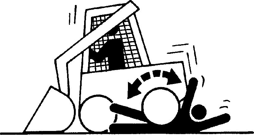
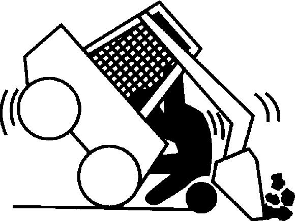
Avoid Machine Tip Over

Use seat belt at all times.
Do not jump if the machine tips. You will be unlikely to jump clear and the machine may crush you.
Load and unload from trucks or trailers carefully. Be sure truck is wide enough and on a firm level surface. Use loading ramps and attach them properly to truck bed
Be careful on slopes. Avoid sharp turns. Balance loads so weight is evenly distributed and load is stable. Carry tools and loads close to the ground to aid visibility and lower center of gravity. Use extra care on wet, soft, rocky, or frozen ground.

Know the capacity of the machine. Do not overload. Be careful with heavy loads. Using oversize buckets or lifting heavy objects reduces machine stability.
Ensure solid footing. Use extra care in soft ground conditions or on structures that may not uniformly support the wheels especially when raising the boom. Do not operate close to banks or open excavations that may cave in and cause machine to tip or fall.
Operating On Slopes
Avoid side slope travel whenever possible. When working on steep slopes, travel as straight up and down as possible and keep the heavy end of the vehicle uphill to prevent machine tip over.
Carry the load as low as possible for maximum stability and visibility.
Select low speed before starting down slope. The slope on which you can operate safely will be limited by ground condition and the load being handled.
Be alert to wind direction and velocity.
Operating Or Traveling On Public Roads
Machines that work near vehicle traffic or travel slower than normal highway speeds must have proper lighting and markings to assure they are visible to other drivers. Install additional lights, beacons, slow moving vehicle (SMV) emblems, or other devices and use as required to make the machine visible and identify it as a work machine. Check state and local regulations to assure compliance. Keep these devices clean and in working condition.
Inspect and Maintain ROPS
A damaged roll-over protective structure (ROPS) should be replaced, not reused.
The protection offered by ROPS will be impaired if ROPS is subjected to structural damage, is involved in an overturn incident, or is in any way altered by welding, bending, drilling, or cutting.
If ROPS was loosened or removed for any reason, inspect it carefully before operating the machine again.
Add and Operate Attachments Safely
Always verify compatibility of attachments by contacting your authorized dealer. Adding unapproved attachments may affect machine stability or reliability, and may create a hazard for others near the machine.
Ensure that a qualified person is involved in attachment installation. Add guards to machine if operator protection
Park and Prepare for Service Safely
Warn others of service work. Always park and prepare machine for service or repair properly.
• Park machine on a level surface and lower equipment to the ground.
• Engage park brake.
• Stop engine and remove key.
• Attach a “DO NOT OPERATE” tag in an obvious place in the operator's station.

Securely support machine or attachment before working under it.

• Do not support machine with any hydraulically actuated tools or attachments.
• Do not support machine with cinder blocks or wooden pieces that may crumble or crush.
• Do not support machine with a single jack or other devices that may slip out of place.
• Always install boom lock before working on or around this machine with the loader boom raised.
Understand service procedures before beginning repairs. Keep service area clean and dry. Use two people whenever the engine must be running for service work.
To maintain the ROPS:
• Replace missing hardware using correct grade hardware.
•
• Check hardware torque. Check isolation mounts for damage, looseness or wear;
• Check ROPS for cracks or physical damage. replace them if necessary.
TX03679,000179F -19-20APR01-1/1
is required or recommended. Verify that all connections are secure and attachment responds properly to controls. Carefully read attachment manual and follow all instructions and warnings. In an area free of bystanders and obstructions, carefully operate attachment to learn its characteristics and range of motion.
TX03679,00016F0 -19-24JAN07-1/1
DW90712,00001D1 -19-21AUG09-1/1
Service Cooling System Safely
Explosive release of fluids from pressurized cooling system can cause serious burns.
Shut off engine. Only remove filler cap when cool enough to touch with bare hands. Slowly loosen cap to first stop to relieve pressure before removing completely.
Remove Paint Before Welding or Heating
Avoid potentially toxic fumes and dust.
Hazardous fumes can be generated when paint is heated by welding, soldering, or using a torch.


Remove paint before heating:
• Remove paint a minimum of 100 mm (4 in.) from area to be affected by heating. If paint cannot be removed, wear an approved respirator before heating or welding.
• If you sand or grind paint, avoid breathing the dust. Wear an approved respirator.
• If you use solvent or paint stripper, remove stripper with soap and water before welding. Remove solvent or paint stripper containers and other flammable material from area. Allow fumes to disperse at least 15 minutes before welding or heating.
Do not use a chlorinated solvent in areas where welding will take place.
Make Welding Repairs Safely
IMPORTANT: Disable electrical power before welding. Turn off main battery switch or disconnect positive battery cable. Separate harness connectors to engine and vehicle microprocessors.
Avoid welding or heating near pressurized fluid lines. Flammable spray may result and cause severe burns if pressurized lines fail as a result of heating. Do not let heat go beyond work area to nearby pressurized lines.
Remove paint properly. Do not inhale paint dust or fumes. Use a qualified welding technician for structural repairs.
Do all work in an area that is well ventilated to carry toxic fumes and dust away.
Dispose of paint and solvent properly.
Make sure there is good ventilation. Wear eye protection and protective equipment when welding.
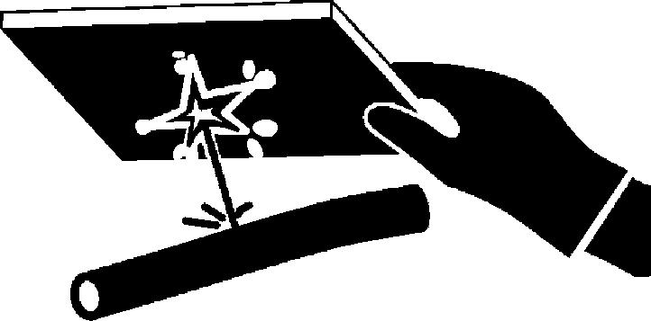
Drive Metal Pins Safely
Always wear protective goggles or safety glasses and other protective equipment before striking hardened parts. Hammering hardened metal parts such as pins and bucket teeth may dislodge chips at high velocity.

Use a soft hammer or a brass bar between hammer and object to prevent chipping.
Service Tires Safely
Explosive separation of a tire and rim parts can cause serious injury or death.
Do not attempt to mount a tire unless you have the proper equipment and experience to perform the job.

Always maintain the correct tire pressure. Do not inflate the tires above the recommended pressure. Never weld or heat a wheel and tire assembly. The heat can cause an increase in air pressure resulting in a tire explosion. Welding can structurally weaken or deform the wheel.
When inflating tires, use a clip-on chuck and extension hose long enough to allow you to stand to one side and NOT in front of or over the tire assembly. Use a safety cage if available.
Check wheels for low pressure, cuts, bubbles, damaged rims or missing lug bolts and nuts.
Handle Cab Door Safely
When servicing machine, be aware that cab door (1) is breakable.

Keep door closed if cab needs to be raised for service. Be aware of surroundings so that door does not come in contact with any objects.
Use care if cab door needs to be removed. To prevent damage to the door, handle with care and store in a secure location.
Section 9001
Diagnostic Trouble Codes (DTCs)
Moderately High Value...........................
001508.00 Hydraulic Oil Temperature Data Above Normal 9001-10-16
Hydraulic Oil Temperature Data Above Normal Diagnostic Procedure.................................................9001-10-16 001508.03 Hydraulic Oil Temperature Out of Range High 9001-10-16
Hydraulic Oil Temperature Out of Range High Diagnostic Procedure 9001-10-17
001508.04 Hydraulic Oil Temperature Out of Range Low 9001-10-17
Hydraulic Oil Temperature Out of Range Low Diagnostic Procedure 9001-10-17
001713.00 Hydraulic Filter
Restriction Switch Data Above Normal 9001-10-18
Hydraulic Filter Restriction Switch Data Above Normal Diagnostic Procedure 9001-10-18
002023.09 No EMU on CAN Bus
Abnormal Data Rate...............................9001-10-19 No EMU Data on CAN Bus
Abnormal Data Range Diagnostic Procedure.................................................9001-10-19
of Range Low
AC Compressor Clutch Output
9001-20-14
Out of Range Low Diagnostic Procedure................................................ 9001-20-14
001550.06 AC Compressor Clutch
Output Out of Range High 9001-20-15
AC Compressor Clutch Output
Out of Range High Diagnostic Procedure 9001-20-15
002000.09 No ECU Data on CAN
Bus Abnormal Data Range................... 9001-20-17
No ECU Data on CAN Bus
Abnormal Data Range Diagnostic Procedure
002228.09 No HCU Data on CAN
Bus Abnormal Data Range...................
No HCU Data on CAN Bus
9001-20-17
Abnormal Data Range Diagnostic Procedure 9001-20-17
003413.04 Door Switch Input Out of Range Low
Seat Switch Input Out of Range Low
Over Ride Switch Input Out of Range Low Diagnostic Procedure....................
521050.04 Aux Flow On-Off Switch Input Out of Range Low
Range High 9001-20-40
Hydraulic Valve Power 1 Out of Range
High Diagnostic Procedure Manual
Control Machines....................................9001-20-41
Hydraulic Valve Power 1 Out of Range
High Diagnostic Procedure EH
Control Machines 9001-20-42
523693.03 Aux Hyd Channel 1 Input
Out of Range High..................................9001-20-43
Aux Hyd Channel 1 Input High
Diagnostic Procedure Manual Control Machines 9001-20-43
Aux Hyd Channel 1 Input High
Diagnostic Procedure EH Control Machines 9001-20-44
523693.04 Aux Hyd Channel 1 Input
Out of Range Low 9001-20-45
Aux Hyd Channel 1 Input Low
Diagnostic Procedure Manual
Control Machines 9001-20-45
Aux Hyd Channel 1 Input Low
Diagnostic Procedure EH Control Machines..................................................9001-20-46
523694.03 Aux Hyd Channel 2 Input
Out of Range High 9001-20-47
Aux Hyd Channel 2 Input High
Diagnostic Procedure Manual
Control Machines....................................9001-20-47
Aux Hyd Channel 2 Input High
Diagnostic Procedure EH Control Machines 9001-20-48
523694.04 Aux Hyd Channel 2 Input
Out of Range Low 9001-20-49
Aux Hyd Channel 2 Input Low
Diagnostic Procedure Manual
Control Machines....................................9001-20-49
Aux Hyd Channel 2 Input Low
Diagnostic Procedure EH Control Machines 9001-20-50
523694.12 Aux Hyd Channel 2 Input
Device Fault.............................................9001-20-51
Aux Hyd Channel 2 Input Device Fault
Diagnostic Procedure 9001-20-51
523822.04 High Flow Switch Input Out of Range Low 9001-20-51
High Flow Switch Input Out of Range Low Diagnostic Procedure.....................9001-20-51
523917.05 Two Speed Output Out of Range Low 9001-20-52
Two Speed Output Out of Range Low
Diagnostic Procedure 9001-20-52
523917.06 Two Speed Output Out of Range High 9001-20-53
Two