Product: WHEEL SCRAPER
Model: 637D WHEEL SCRAPER 20W
Configuration: 637D SCRAPERS 20W00001-00494 (MACHINE) POWERED BY 3306 ENGINE
Disassembly and Assembly
C9 Engines for Caterpillar Built Machines
Media Number -RENR9579-20 Publication Date -01/02/2015 Date Updated -15/08/2018
Valve Mechanism Cover - Remove and Install
SMCS - 1107-010
Removal Procedure
NOTICE
Keep all parts clean from contaminants. Contaminants may cause rapid wear and shortened component life.

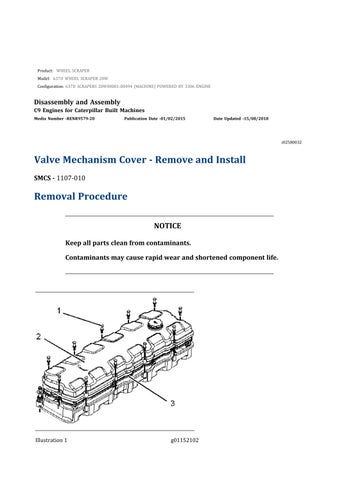
1. Removebolts(1)
2. Removevalvemechanismcover(2)andseal(3).
Installation Procedure
Table1
Required Tools
Tool
A 4C-9612 SiliconeSealant 1
NOTICE
Keep all parts clean from contaminants.
Contaminants may cause rapid wear and shortened component life.

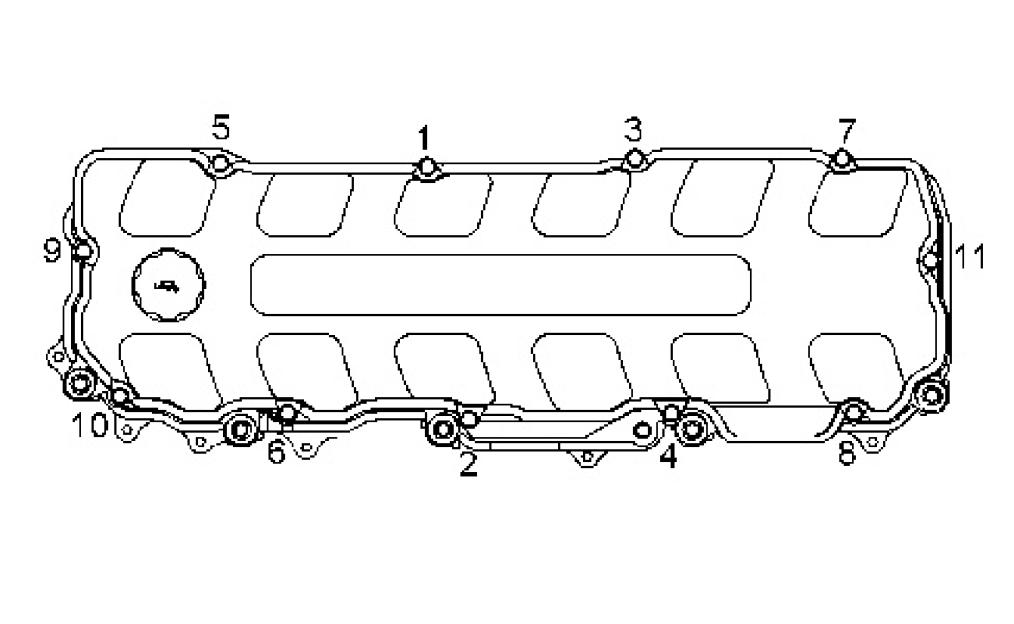
Illustration3 g01138382
1. Positionseal(3)invalvemechanismcover(2) ApplyTooling(A)tobothsidesofthe seal joint Positionvalvemechanismcover(2)andseal(3)onthevalvecoverbase.
2. Installbolts(1).Tightenbolts(1)inanumericalsequencetoatorqueof20±3N·m(1 5± 2lbft).
Product: WHEEL SCRAPER
Model: 637D WHEEL SCRAPER 20W
Configuration: 637D SCRAPERS 20W00001-00494 (MACHINE) POWERED BY 3306 ENGINE
Disassembly and Assembly
C9 Engines for Caterpillar Built Machines
Media Number -RENR9579-20 Publication Date -01/02/2015 Date Updated -15/08/2018
Valve Mechanism Cover Base - Remove and Install
SMCS - 1120-010
Removal
Procedure
Start By:
a Removethevalvemechanismcover RefertoDisassemblyandAssembly,"Valve MechanismCover-RemoveandInstall".
NOTICE
Keep all parts clean from contaminants. Contaminants may cause rapid wear and shortened component life.

Illustration1 g01140735
1. Disconnectsensor(4)andharnessassembly(6)fromvalvecoverbase(5).
2. Removebolt(1)andtheclipthatholdstheharnessassembly.
3. Disconnectharnessassemblies(3).
4. Removebolts(2),thewashers,andthesprings
5. Removevalvecoverbase(5)andtheseal.
Installation Procedure
NOTICE
Keep all parts clean from contaminants.
Contaminants may cause rapid wear and shortened component life.
Illustration2 g01140735

Illustration3 g01061297
1. Positionthesealandvalvecoverbase(5)onthecylinderhead.
2. Installthesprings,thewashers,andbolts(2).Tightenbolts(2)inanumericalseque nce
3. Connectharnessassemblies(3).
4. Installtheclipandbolt(1)thatholdstheharnessassembly.
5. Connectharnessassembly(6)tovalvecoverbase(5).Tightentheboltstoatorqueof 6±1N·m(53±9lbin).
6. Connectsensor(4)tovalvecoverbase(5).
End By:
a. Installthevalvemechanismcover.RefertoDisassemblyandAssembly,"ValveMechani sm Cover-RemoveandInstall".
Product: WHEEL SCRAPER
Model: 637D WHEEL SCRAPER 20W
Configuration: 637D SCRAPERS 20W00001-00494 (MACHINE) POWERED BY 3306 ENGINE
Disassembly and Assembly
C9 Engines for Caterpillar Built Machines
Media Number -RENR9579-20 Publication Date -01/02/2015 Date Updated -15/08/2018
Rocker Arm and Shaft - Remove
SMCS - 1102-011
Removal Procedure
Start By:
i02884496
a Removethevalvemechanismcover RefertoDisassemblyandAssembly,"Valve MechanismCover-RemoveandInstall".
NOTICE
Keep all parts clean from contaminants. Contaminants may cause rapid wear and shortened component life.
1. Placeidentificationmarksoneachoftherockerarmsinordertoidentifytheproperlo cation forinstallation

Illustration1 g00953116
2. Loosennuts(3)androckerarmadjustmentscrews(2).
3. Removebolts(1)androckershaft(4).
4. Removethepushrodsandthevalvebridges
Product: WHEEL SCRAPER
Model: 637D WHEEL SCRAPER 20W
Configuration: 637D SCRAPERS 20W00001-00494 (MACHINE) POWERED BY 3306 ENGINE
Disassembly and Assembly
C9 Engines for Caterpillar Built Machines
Media Number -RENR9579-20 Publication Date -01/02/2015
Rocker Arm - Disassemble
SMCS - 1123-015
Disassembly Procedure
Start By:
Date Updated -15/08/2018
a Removetherockerarmandshaft RefertoDisassemblyandAssembly,"RockerArman d Shaft-Remove".
NOTICE
Keep all parts clean from contaminants.
Contaminants may cause rapid wear and shortened component life.
Note: Placeanidentificationmarkoneachofthecomponentsoftherockershaftforinstallat ion purposes.

Illustration1 g01160012
Personal injury can result from being struck by parts propelled by a released spring force.
Make sure to wear all necessary protective equipment.
Follow the recommended procedure and use all recommended tooling to release the spring force.
1. Removeplug(2)fromrockershaft(1).
2. Removestand(6),inletrockerarm(5),spring(4),andexhaustrockerarm(3)fromro cker shaft(1).
Product: WHEEL SCRAPER
Model: 637D WHEEL SCRAPER 20W
Configuration: 637D SCRAPERS 20W00001-00494 (MACHINE) POWERED BY 3306 ENGINE
Disassembly and Assembly
C9 Engines for Caterpillar Built Machines
Media Number -RENR9579-20 Publication Date -01/02/2015 Date Updated -15/08/2018
Rocker Arm - Assemble
SMCS - 1123-016
Assembly Procedure
NOTICE
Keep all parts clean from contaminants.
Contaminants may cause rapid wear and shortened component life.
1. Lubricateallcomponentsoftherockerarmshaftwithcleanengineoil
Illustration1 g01160012
Improper assembly of parts that are spring loaded can cause bodily injury.
To prevent possible injury, follow the established assembly procedure and wear protective equipment.
2. Installexhaustrockerarm(3),spring(4),inletrockerarm(5),andstand(6)onrocker shaft (1).
3. Installplug(2)intorockershaft(1).
End By:
a Installtherockerarmandshaft RefertoDisassemblyandAssembly,"RockerArmand Shaft-Install".
Product: WHEEL SCRAPER
Model: 637D WHEEL SCRAPER 20W
Configuration: 637D SCRAPERS 20W00001-00494 (MACHINE) POWERED BY 3306 ENGINE
Disassembly and Assembly
C9 Engines for Caterpillar Built Machines Media Number -RENR9579-20
Rocker Arm and Shaft - Install
SMCS - 1102-012
Installation Procedure Table1
Required Tools
i04506590
Keep all parts clean from contaminants.
Contaminants may cause rapid wear and shortened component life.
1. ApplyTooling(A)tobothendsofthepushrods.
2. Lubricatethepushrodswithcleanengineoil Installthepushrodsandthevalvebridge s.
Illustration1 g00953116
3. Positionrockershaft(4)onthecylinderhead.Installbolts(1).

Illustration2 g02685496 Rockershaftholddownboltstighteningsequence
4. Tightenbolts(1)inthesequenceshown.Tightenbolts(1)tostandardtorque.
5. ApplyTooling(A)toeachofthebottomfacesoftherockerarms
6. Positionrockerarmadjustmentscrews(2)andtightennuts(3).Adjustthevalvelasho fthe rockerarms RefertoTestingandAdjusting,"EngineValveLash-Inspect/Adjust".
End By:
a. Installthevalvemechanismcover.RefertoDisassemblyandAssembly,"ValveMechani sm Cover-RemoveandInstall".