Safety rules

INTRODUCTION
BT09A213 1 84423866 25/07/2011 6
Basic instructions - How To Use and Navigate Through This Manual
Technical Information
This manual has been produced by a new technical information system. This new system is designed to deliver technical information electronically through Web delivery, DVD and in paper manuals. A coding system called SAP has been developed to link the technical information to other Product Support functions, e.g., Warranty.
Technical information is written to support the maintenance and service of the functions or systems on a customer's machine. When a customer has a concern on his machine it is usually because a function or system on his machine is not working at all, is not working efficiently, or is not responding correctly to his commands. When you refer to the technical information in this manual to resolve that customer's concern, you will find all the information classified using the SAP coding, according to the functions or systems on that machine. Once you have located the technical information for that function or system then you will find all the mechanical, electrical or hydraulic devices, components, assemblies and sub assemblies for that function or system. You will also find all the types of information that have been written for that function or system, the technical data (specifications), the functional data (how it works), the diagnostic data (fault codes and troubleshooting) and the service data (remove, install adjust, etc.).
By integrating SAP coding into technical information , you will be able to search and retrieve just the right piece of technical information you need to resolve that customer's concern on his machine. This is made possible by attaching 3 categories to each piece of technical information during the authoring process.
The first category is the Location, the second category is the Information Type and the third category is the Product:
• LOCATION - is the component or function on the machine, that the piece of technical information is going to describe e.g. Fuel tank.
• INFORMATION TYPE - is the piece of technical information that has been written for a particular component or function on the machine e.g. Capacity would be a type of Technical Data that would describe the amount of fuel held by the Fuel tank.
• PRODUCT - is the model for which the piece of technical information is written.
Every piece of technical information will have those 3 categories attached to it. You will be able to use any combination of those categories to find the right piece of technical information you need to resolve that customer's concern on his machine.
That information could be:
• the description of how to remove the cylinder head
• a table of specifications for a hydraulic pump
• a fault code
• a troubleshooting table
• a special tool 84423866
INTRODUCTION
25/07/2011 7
How to Use this Manual
This manual is divided into Sections. Each Section is then divided into Chapters. Contents pages are included at the beginning of the manual, then inside every Section and inside every Chapter. An alphabetical Index is included at the end of a Chapter. Page number references are included for every piece of technical information listed in the Chapter Contents or Chapter Index.
Each Chapter is divided into four Information types:
• Technical Data (specifications) for all the mechanical, electrical or hydraulic devices, components and, assemblies.
• Functional Data (how it works) for all the mechanical, electrical or hydraulic devices, components and assemblies.
• Diagnostic Data (fault codes, electrical and hydraulic troubleshooting) for all the mechanical, electrical or hydraulic devices, components and assemblies.
• Service Data (remove disassembly, assemble, install) for all the mechanical, electrical or hydraulic devices, components and assemblies.
Sections
Sections are grouped according to the main functions or a systems on the machine. Each Section is identified by a letter A, B, C etc. The amount of Sections included in the manual will depend on the type and function of the machine that the manual is written for. Each Section has a Contents page listed in alphabetic/numeric order. This table illustrates which Sections could be included in a manual for a particular product.
SECTION
A - Hydraulic – Pneumatic – Electrical – Electronic Systems
INTRODUCTION
B - Engine and PTO In C - Transmission, Drive and PTO Out D - Axles, Brakes and Steering
E - Frame and Cab
F - Frame Positioning
G - Tool Positioning
H - Hitch and Working Tool
Landscaping
Processing
Field Processing PRODUCT Tractors X X X X X X X X Vehicles with working arms: backhoes, excavators, skid steers, ..... X X X X X X X X X Combines, forage harvesters, balers, X X X X X X X X X X Seeding, planting, floating, spraying equipment, .... X X X X X X X X X Mounted equipment and tools, X X X X 84423866 25/07/2011 8
J - Excavating and
K - Crop
L -
INTRODUCTION
Section Contents
SECTION LETTER DESCRIPTION
HYDRAULIC –PNEUMATIC –ELECTRICAL –ELECTRONIC SYSTEMS
A
This Section covers the main systems that interact with most of the functions of the product. It includes the central parts of the hydraulic, electrical, electronic, pneumatic, lighting and grease lubrication systems. The components that are dedicated to a specific function are listed in the Chapter where all the technical information for that function is included.
ENGINE AND PTO IN B
This Section covers all the functions related to the production of power to move the machine and to drive various devices. In the case of a pulled-type machine, this Section covers the power take-off function where power is provided from the towing machine.
TRANSMISSION, DRIVE AND PTO OUT C
AXLES, BRAKES AND STEERING D
FRAME AND CAB E
This Section covers all the functions related to the transmission of power from the engine to the axles and to internal or external devices. This Section also covers the power take-off function where power is provided to the pull-type machine and additional Process Drive functions.
This Section covers all the functions related to moving the machine, including tracks, wheels, steering and braking. It covers all the axles; both driven axles and non-driven axles, including any axle suspension.
This Section covers all the main functions and systems related to the structure and the body of the machine, including the frame, the shields, the operators cab and the platform. The functions related to the positioning of the machine frame are included in Section F, Frame Positioning.
FRAME POSITIONING F
TOOL POSITIONING G
HITCH AND WORKING TOOL
H
This Section covers all the main functions and systems related to positioning of the machine frame or to positioning the attachment on the supporting machine frame.
This Section covers all the functions related to the final and/or automatic positioning of the tool once the tool is positioned using the Working Arm or the machine frame.
This Section covers all the functions related to the articulated or single arms mounted on the front or rear of the machine. A working arm can have various tools and quick couplers mounted on to it. The tools and quick couplers are included in Section J, Excavating and Landscaping.
EXCAVATING AND LANSCAPING J
This Section covers all the functions related to the specific tools that mount on the front, rear or beside the machine. The tools described here can be mounted with the positioning systems (lifting, side shift, swing) listed in Section G Tool Positioning. This Section covers all the quick coupling systems, located between the tool and the positioning system. The tools used for field preparation, soil preparation and treatment, planting and seeding are included.
CROP PROCESSING K
FIELD PROCESSING L
This Section covers all the functions related to crop processing. Examples of crop processing include threshing, baling, windrowing, cutting and conditioning.
This Section covers all the field processing functions of the machine. Examples of field process include seeding, fertilizer application, seedbed preparation and chemical application.
84423866 25/07/2011 9
INTRODUCTION
This manual contains these Sections:
Contents
INTRODUCTION
HYDRAULIC – PNEUMATIC – ELECTRICAL – ELECTRONIC SYSTEMS
ENGINE AND PTO IN
Chapters
Each Chapter is identified by a letter and number combination e.g. Engine B.10.A The first letter is identical to the Section letter i.e. Chapter B.10 is inside Section B, Engine and PTO In.
CONTENTS
The Chapter Contents lists all the technical data (specifications), functional data (how it works), service data (remove, install adjust, etc..) and diagnostic data (fault codes and troubleshooting) that have been written in that Chapter for that function or system on the machine.
Contents
TECHNICAL DATA
ENGINE AND PTO IN ENGINE _ 10.A
ENGINE - General specification (B.10.A)
FUNCTIONAL DATA
ENGINE - Dynamic description (B.10.A)
SERVICE
ENGINE - Remove (B.10.A)
DIAGNOSTIC ENGINE - Troubleshooting (B.10.A)
INDEX
The Chapter Index lists in alphabetical order all the types of information (called Information Units) that have been written in that Chapter for that function or system on the machine.
Index
ENGINE - Dynamic description (B.10.A)
ENGINE - General specification (B.10.A)
ENGINE - Remove (B.10.A)
ENGINE - Troubleshooting (B.10.A)
ENGINE AND PTO IN - B ENGINE
B FRAME POSITIONING F CROP PROCESSING K
A
84423866 25/07/2011 10
Information Units and Information Search
Each chapter is composed of information units. Each information unit has the SAP code shown in parentheses which indicates the function and the type of information written in that information unit. Each information unit has a page reference within that Chapter. The information units provide a quick and easy way to find just the right piece of technical information you are looking for.
Example information unit
Stack valve - Sectional View (A.10.A.18)
Information Unit SAP code A 10.A 18
SAP code classification
–
Systems
Primary hydraulic power
CRIL03J033E01A 1
Navigate to the correct information unit you are searching for by identifying the function and information type from the SAP code.
• (1) Function and (2) Information type.
• (A) corresponds to the sections of the repair manual.
(B) corresponds to the chapters of the repair manual.
(C) corresponds to the type of information listed in the chapter contents, Technical Data, Functional Data, Diagnostic or Service.
(A) and (B) are also shown in the page numbering on the page footer. THE REST OF THE CODING IS NOT LISTED IN ALPHANUMERIC ORDER IN THIS MANUAL.

• You will find a table of contents at the beginning and end of each section and chapter. You will find an alphabetical index at the end of each chapter.
• By referring to (A), (B) and (C) of the coding, you can follow the contents or index (page numbers) and quickly find the information you are looking for.
Page Header and Footer
The page header will contain the following references:
• Section and Chapter description
The page footer will contain the following references:
• Publication number for that Manual, Section or Chapter.
• Version reference for that publication.
• Publication date
• Section, chapter and page reference e.g. A.10.A / 9
84423866 25/07/2011
INTRODUCTION
Hydraulic –Pneumatic
Electrical –Electronic
Stack valve
11
Basic instructions - Important notice regarding equipment servicing
All repair and maintenance work listed in this manual must be carried out only by qualified dealership personnel, strictly complying with the instructions given, and using, whenever possible, the special tools.
Anyone who performs repair and maintenance operations without complying with the procedures provided herein shall be responsible for any subsequent damages.
The manufacturer and all the organizations of its distribution chain, including - without limitation - national, regional, or local dealers, reject any responsibility for damages caused by parts and/or components not approved by the manufacturer, including those used for the servicing or repair of the product manufactured or marketed by the manufacturer. In any case, no warranty is given or attributed on the product manufactured or marketed by the manufacturer in case of damages caused by parts and/or components not approved by the manufacturer.
The information in this manual is up-to-date at the date of the publication. It is the policy of the manufacturer for continuous improvement. Some information could not be updated due to modifications of a technical or commercial type, or changes to the laws and regulations of different countries.
In case of questions, refer to your CASE CONSTRUCTION Sales and Service Networks.
INTRODUCTION
84423866 25/07/2011 12
Basic instructions - Shop and Assembly
SHIMMING
For each adjustment operation, select adjusting shims and measure individually using a micrometer, then add up the recorded values. Do not rely on measuring the entire shimming set, which may be incorrect, or the rated value indicated on each shim.
ROTATING SHAFT SEALS
For correct rotating shaft seal installation, proceed as follows:
• before assembly, allow the seal to soak in the oil it will be sealing for at least thirty minutes.
• thoroughly clean the shaft and check that the working surface on the shaft is not damaged.
• position the sealing lip facing the fluid; with hydrodynamic lips, take into consideration the shaft rotation direction and position the grooves so that they will deviate the fluid towards the inner side of the seal.
• coat the sealing lip with a thin layer of lubricant (use oil rather than grease) and fill the gap between the sealing lip and the dust lip on double lip seals with grease.
• insert the seal in its seat and press down using a flat punch or seal installation tool. Do not tap the seal with a hammer or mallet.
• whilst inserting the seal, check that it is perpendicular to the seat; once settled, make sure that it makes contact with the thrust element, if required.
• to prevent damaging the seal lip on the shaft, position a protective guard during installation operations.
O-RING SEALS
Lubricate the O-RING seals before inserting them in the seats, this will prevent them from overturning and twisting, which would jeopardise sealing efficiency.
SEALING COMPOUNDS
Apply one of the following sealing compounds on the mating surfaces when specified: SILMATE® RTV1473, or LOCTITE® RTV 598 or LOCTITE® INSTANT GASKET 587 BLUE Before applying the sealing compound, prepare the surfaces as directed on product container or as follows:
• remove any incrustations using a metal brush.
• thoroughly de-grease the surfaces using a locally approved cleaning agent such as safety solvent or brake parts cleaner.
SPARE PARTS
Only use "CNH Original Parts" or " CASE CONSTRUCTION Parts".
Only genuine spare parts guarantee the same quality, duration and safety as original parts, as they are the same parts that are assembled during standard production. Only "CNH Original Parts" or " CASE CONSTRUCTION Parts" can offer this guarantee.
When ordering spare parts, always provide the following information:
• machine model (commercial name) and serial number
• part number of the ordered part, which can be found in the "Microfiches" or the "Service Parts Catalogue", used for order processing 84423866
INTRODUCTION
13
25/07/2011
PROTECTING THE ELECTRONIC/ ELECTRICAL SYSTEMS DURING CHARGING OR WELDING
To avoid damage to the electronic/electrical systems, always observe the following:

1. Never make or break any of the charging circuit connections, including the battery connections, when the engine is running.
2. Never short any of the charging components to ground.
3. Always disconnect the ground cable from the battery before arc welding on the combine or on any header attached to the combine.
• position the welder ground clamp as close to the welding area as possible
• if welding in close proximity to a computer module, then the module should be removed from the combine
• never allow welding cables to lay on, near or across any electrical wiring or electronic component while welding is in progress
4. Always disconnect the negative cable from the battery when charging the battery in the combine with a battery charger.
NOTICE: If welding must be performed on the unit, either the combine or the header (if it is attached), the battery ground cable must be disconnected from the combine battery. The electronic monitoring system and charging system will be damaged if this is not done.
Remove the battery ground cable. Reconnect the cable when welding is completed.
WARNING
Battery acid causes severe burns. Batteries contain sulfuric acid. Avoid contact with skin, eyes or clothing. Antidote - EXTERNAL: flush with water. INTERNAL: drink large quantities of water or milk. Follow with milk of magnesia, beaten egg or vegetables oil. Call physician immediately. EYES: flush with water for 15 minutes and get prompt medical attention.
TOOLS
The tools that CASE CONSTRUCTION suggests and illustrate in this manual have been:
• specifically researched and designed for use with CASE CONSTRUCTION machines
• essential for reliable repair operations
• accurately built and rigorously tested so as to offer efficient and long-lasting operation
By using these tools, repair personnel will benefit from:
• operating in optimal technical conditions
• obtaining the best results
• saving time and effort
• working in safe conditions
NOTE: The terms "front", "rear", "right-hand" and "left-hand" (when referred to different parts) are determined from the rear, facing in the direction of travel of the machine during operation.
INTRODUCTION
84-110
84423866 25/07/2011 14
Torque - Minimum tightening torques for normal assembly
NOTE: M4 through M8 hardware torque specifications are shown in pound-inches. M10 through M24 hardware torque specifications are shown in pound-feet.
INTRODUCTION
S-Series, T-Series METRIC NON-FLANGED HARDWARE NOM. SIZE CLASS 8.8 BOLT and CLASS 8 NUT CLASS 10.9 BOLT and CLASS 10 NUT LOCKNUT CL.8 W/CL8.8 BOLT LOCKNUT CL.10 W/CL10.9 BOLT UNPLATED PLATED W/ZnCr UNPLATED PLATED W/ZnCr M4 2.2 N·m (19 lb in) 2.9 N·m (26 lb in) 3.2 N·m (28 lb in) 4.2 N·m (37 lb in) 2 N·m (18 lb in) 2.9 N·m (26 lb in) M5 4.5 N·m (40 lb in) 5.9 N·m (52 lb in) 6.4 N·m (57 lb in) 8.5 N·m (75 lb in) 4 N·m (36 lb in) 5.8 N·m (51 lb in) M6 7.5 N·m (66 lb in) 10 N·m (89 lb in) 11 N·m (96 lb in) 15 N·m (128 lb in) 6.8 N·m (60 lb in) 10 N·m (89 lb in) M8 18 N·m (163 lb in) 25 N·m (217 lb in) 26 N·m (234 lb in) 35 N·m (311 lb in) 17 N·m (151 lb in) 24 N·m (212 lb in) M10 37 N·m (27 lb ft) 49 N·m (36 lb ft) 52 N·m (38 lb ft) 70 N·m (51 lb ft) 33 N·m (25 lb ft) 48 N·m (35 lb ft) M12 64 N·m (47 lb ft) 85 N·m (63 lb ft) 91 N·m (67 lb ft) 121 N·m (90 lb ft) 58 N·m (43 lb ft) 83 N·m (61 lb ft) M16 158 N·m (116 lb ft) 210 N·m (155 lb ft) 225 N·m (166 lb ft) 301 N·m (222 lb ft) 143 N·m (106 lb ft) 205 N·m (151 lb ft) M20 319 N·m (235 lb ft) 425 N·m (313 lb ft) 440 N·m (325 lb ft) 587 N·m (433 lb ft) 290 N·m (214 lb ft) 400 N·m (295 lb ft) M24 551 N·m (410 lb ft) 735 N·m (500 lb ft) 762 N·m (560 lb ft) 1016 N·m (750 lb ft) 501 N·m (370 lb ft) 693 N·m (510 lb ft)
84423866 25/07/2011 15
METRIC FLANGED HARDWARE
INTRODUCTION
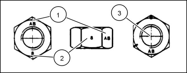
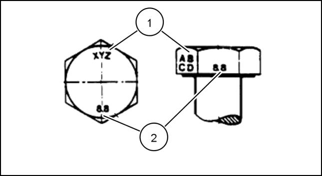
NOM. SIZE CLASS 8.8 BOLT and CLASS 8 NUT CLASS 10.9 BOLT and CLASS 10 NUT LOCKNUT CL.8 W/CL8.8 BOLT LOCKNUT CL.10 W/CL10.9 BOLT UNPLATED PLATED W/ZnCr UNPLATED PLATED W/ZnCr M4 2.4 N·m (21 lb in) 3.2 N·m (28 lb in) 3.5 N·m (31 lb in) 4.6 N·m (41 lb in) 2.2 N·m (19 lb in) 3.1 N·m (27 lb in) M5 4.9 N·m (43 lb in) 6.5 N·m (58 lb in) 7.0 N·m (62 lb in) 9.4 N·m (83 lb in) 4.4 N·m (39 lb in) 6.4 N·m (57 lb in) M6 8.3 N·m (73 lb in) 11 N·m (96 lb in) 12 N·m (105 lb in) 16 N·m (141 lb in) 7.5 N·m (66 lb in) 11 N·m (96 lb in) M8 20 N·m (179 lb in) 27 N·m (240 lb in) 29 N·m (257 lb in) 39 N·m (343 lb in) 18 N·m (163 lb in) 27 N·m (240 lb in) M10 40 N·m (30 lb ft) 54 N·m (40 lb ft) 57 N·m (42 lb ft) 77 N·m (56 lb ft) 37 N·m (27 lb ft) 53 N·m (39 lb ft) M12 70 N·m (52 lb ft) 93 N·m (69 lb ft) 100 N·m (74 lb ft) 134 N·m (98 lb ft) 63 N·m (47 lb ft) 91 N·m (67 lb ft) M16 174 N·m (128 lb ft) 231 N·m (171 lb ft) 248 N·m (183 lb ft) 331 N·m (244 lb ft) 158 N·m (116 lb ft) 226 N·m (167 lb ft) M20 350 N·m (259 lb ft) 467 N·m (345 lb ft) 484 N·m (357 lb ft) 645 N·m (476 lb ft) 318 N·m (235 lb ft) 440 N·m (325 lb ft) M24 607 N·m (447 lb ft) 809 N·m (597 lb ft) 838 N·m (618 lb ft) 1118 N·m (824 lb ft) 552 N·m (407 lb ft) IDENTIFICATION Metric Hex head and carriage bolts, classes 5.6 and up 20083680 1 1. Manufacturer's Identification 2. Property Class Metric Hex nuts and locknuts, classes 05 and up 20083681 2 84423866 25/07/2011 16
1. Manufacturer's Identification
2. Property Class
3. Clock Marking of Property Class and Manufacturer's Identification
i.e. marks 60 ° apart indicate Class 10 properties, and marks 120 ° apart indicate Class 8.
INCH NON-FLANGED HARDWARE
NOTE: For Imperial Units, 1/4 in and 5/16 in hardware torque specifications are shown in pound-inches.
in through 1 in hardware torque specifications are shown in pound-feet.
INTRODUCTION
(Optional),
NOMINAL SIZE SAE GRADE 5 BOLT and NUT SAE GRADE 8 BOLT and NUT LOCKNUT GrB W/ Gr5 BOLT LOCKNUT GrC W/ Gr8 BOLT UNPLATED or PLATED SILVER PLATED W/ZnCr GOLD UNPLATED or PLATED SILVER PLATED W/ZnCr GOLD 1/4 8 N·m (71 lb in) 11 N·m (97 lb in) 12 N·m (106 lb in) 16 N·m (142 lb in) 8.5 N·m (75 lb in) 12.2 N·m (109 lb in) 5/16 17 N·m (150 lb in) 23 N·m (204 lb in) 24 N·m (212 lb in) 32 N·m (283 lb in) 17.5 N·m (155 lb in) 25 N·m (220 lb in) 3/8 30 N·m (22 lb ft) 40 N·m (30 lb ft) 43 N·m (31 lb ft) 57 N·m (42 lb ft) 31 N·m (23 lb ft) 44 N·m (33 lb ft) 7/16 48 N·m (36 lb ft) 65 N·m (48 lb ft) 68 N·m (50 lb ft) 91 N·m (67 lb ft) 50 N·m (37 lb ft) 71 N·m (53 lb ft) 1/2 74 N·m (54 lb ft) 98 N·m (73 lb ft) 104 N·m (77 lb ft) 139 N·m (103 lb ft) 76 N·m (56 lb ft) 108 N·m (80 lb ft) 9/16 107 N·m (79 lb ft) 142 N·m (105 lb ft) 150 N·m (111 lb ft) 201 N·m (148 lb ft) 111 N·m (82 lb ft) 156 N·m (115 lb ft) 5/8 147 N·m (108 lb ft) 196 N·m (145 lb ft) 208 N·m (153 lb ft) 277 N·m (204 lb ft) 153 N·m (113 lb ft) 215 N·m (159 lb ft) 3/4 261 N·m (193 lb ft) 348 N·m (257 lb ft) 369 N·m (272 lb ft) 491 N·m (362 lb ft) 271 N·m (200 lb ft) 383 N·m (282 lb ft) 7/8 420 N·m (310 lb ft) 561 N·m (413 lb ft) 594 N·m (438 lb ft) 791 N·m (584 lb ft) 437 N·m (323 lb ft) 617 N·m (455 lb ft) 1 630 N·m (465 lb ft) 841 N·m (620 lb ft) 890 N·m (656 lb ft) 1187 N·m (875 lb ft) 654 N·m (483 lb ft) 924 N·m (681 lb ft)
3/8
17
84423866 25/07/2011
FLANGED HARDWARE NOMINAL SIZE SAE GRADE 5 BOLT and NUT SAE GRADE 8 BOLT and NUT LOCKNUT GrF W/ Gr5 BOLT LOCKNUT GrG W/ Gr8 BOLT UNPLATED or PLATED SILVER PLATED W/ZnCr GOLD UNPLATED or PLATED SILVER PLATED W/ZnCr GOLD 1/4 9 N·m (80 lb in) 12 N·m (106 lb in) 13 N·m (115 lb in) 17 N·m (150 lb in) 8 N·m (71 lb in) 12 N·m (106 lb in) 5/16 19 N·m (168 lb in) 25 N·m (221 lb in) 26 N·m (230 lb in) 35 N·m (310 lb in) 17 N·m (150 lb in) 24 N·m (212 lb in) 3/8 33 N·m (25 lb ft) 44 N·m (33 lb ft) 47 N·m (35 lb ft) 63 N·m (46 lb ft) 30 N·m (22 lb ft) 43 N·m (32 lb ft) 7/16 53 N·m (39 lb ft) 71 N·m (52 lb ft) 75 N·m (55 lb ft) 100 N·m (74 lb ft) 48 N·m (35 lb ft) 68 N·m (50 lb ft) 1/2 81 N·m (60 lb ft) 108 N·m (80 lb ft) 115 N·m (85 lb ft) 153 N·m (113 lb ft) 74 N·m (55 lb ft) 104 N·m (77 lb ft) 9/16 117 N·m (86 lb ft) 156 N·m (115 lb ft) 165 N·m (122 lb ft) 221 N·m (163 lb ft) 106 N·m (78 lb ft) 157 N·m (116 lb ft) 5/8 162 N·m (119 lb ft) 216 N·m (159 lb ft) 228 N·m (168 lb ft) 304 N·m (225 lb ft) 147 N·m (108 lb ft) 207 N·m (153 lb ft) 3/4 287 N·m (212 lb ft) 383 N·m (282 lb ft) 405 N·m (299 lb ft) 541 N·m (399 lb ft) 261 N·m (193 lb ft) 369 N·m (272 lb ft) 7/8 462 N·m (341 lb ft) 617 N·m (455 lb ft) 653 N·m (482 lb ft) 871 N·m (642 lb ft) 421 N·m (311 lb ft) 594 N·m (438 lb ft) 1 693 N·m (512 lb ft) 925 N·m (682 lb ft) 979 N·m (722 lb ft) 1305 N·m (963 lb ft) 631 N·m (465 lb ft) 890 N·m (656 lb ft)
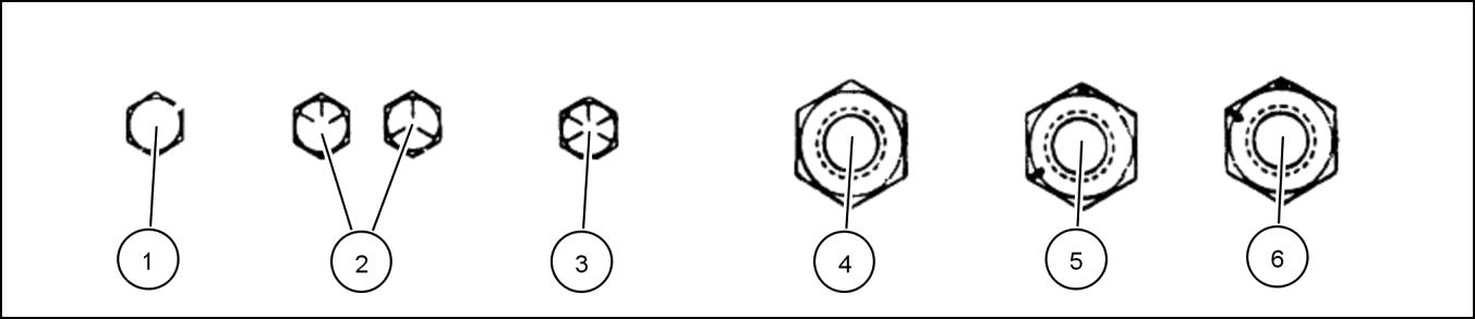
Inch Bolts and free-spinning nuts 20083682 3 Grade Marking Examples SAE Grade Identification 1 Grade 2 - No Marks 4 Grade 2 Nut - No Marks 2 Grade 5 - Three Marks 5 Grade 5 Nut - Marks 120 ° Apart 3 Grade 8 - Five Marks 6 Grade 8 Nut - Marks 60 ° Apart 84423866 25/07/2011 18
INTRODUCTION INCH
IDENTIFICATION
Inch Lock Nuts, All Metal (Three optional methods)
INTRODUCTION
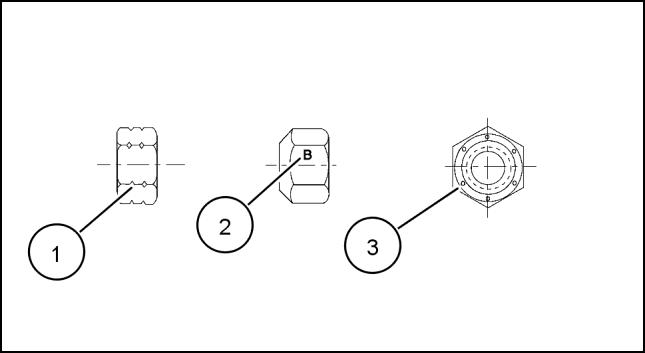
Grade Identification 20090268 4 Grade Corner Marking Method (1) Flats Marking Method (2) Clock Marking Method (3) Grade A No Notches No Mark No Marks Grade B One Circumferential Notch Letter B Three Marks Grade C Two Circumferential Notches Letter C Six Marks 84423866 25/07/2011 19
Torque - Standard torque data for hydraulics
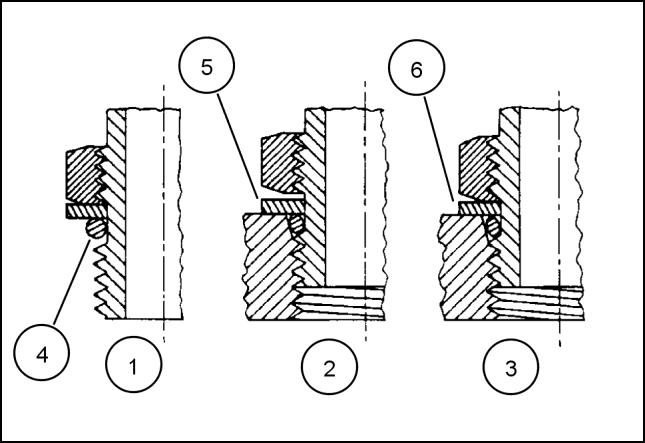
INSTALLATION OF ADJUSTABLE FITTINGS IN STRAIGHT THREAD O RING BOSSES
1. Lubricate the O-ring by coating it with a light oil or petroleum. Install the O-ring in the groove adjacent to the metal backup washer which is assembled at the extreme end of the groove (4).
2. Install the fitting into the SAE straight thread boss until the metal backup washer contacts the face of the boss (5)
NOTE: Do not over tighten and distort the metal backup washer.
3. Position the fitting by turning out (counterclockwise) up to a maximum of one turn. Holding the pad of the fitting with a wrench, tighten the locknut and washer against the face of the boss (6)
STANDARD TORQUE DATA FOR HYDRAULIC TUBES AND FITTINGS
37°
These torques are not recommended for tubes of 12.7 mm (1/2 in) OD and larger with wall thickness of 0.889 mm (0.035 in) or less. The torque is specified for 0.889 mm (0.035 in) wall tubes on each application individually.
Before installing and torquing 37 ° flared fittings, clean the face of the flare and threads with a clean solvent or Loctite cleaner and apply hydraulic sealant LOCTITE® 569 to the 37 ° flare and the threads. Install fitting and torque to specified torque, loosen fitting and retorque to specifications.
INTRODUCTION
23085659 1
TUBE NUTS FOR
FLARED FITTINGS O-RING BOSS PLUGS ADJUSTABLE FITTING LOCKNUTS, SWIVEL
37° SEATS SIZE TUBING OD THREAD SIZE TORQUE TORQUE 4 6.4 mm (1/4 in) 7/16-20 12 - 16 N·m (9 - 12 lb ft) 8 - 14 N·m (6 - 10 lb ft) 5 7.9 mm (5/16 in) 1/2-20 16 - 20 N·m (12 - 15 lb ft) 14 - 20 N·m (10 - 15 lb ft) 6 9.5 mm (3/8 in) 9/16-18 29 - 33 N·m (21 - 24 lb ft) 20 - 27 N·m (15 - 20 lb ft) 8 12.7 mm (1/2 in) 3/4-16 47 - 54 N·m (35 - 40 lb ft) 34 - 41 N·m (25 - 30 lb ft) 10 15.9 mm (5/8 in) 7/8-14 72 - 79 N·m (53 - 58 lb ft) 47 - 54 N·m (35 - 40 lb ft) 12 19.1 mm (3/4 in) 1-1/16-12 104 - 111 N·m (77 - 82 lb ft) 81 - 95 N·m (60 - 70 lb ft) 14 22.2 mm (7/8 in) 1-3/16-12 122 - 136 N·m (90 - 100 lb ft) 95 - 109 N·m (70 - 80 lb ft) 16 25.4 mm (1 in) 1-5/16-12 149 - 163 N·m (110 - 120 lb ft) 108 - 122 N·m (80 - 90 lb ft) 20 31.8 mm (1-1/4 in) 1-5/8-12 190 - 204 N·m (140 - 150 lb ft) 129 - 158 N·m (95 - 115 lb ft) 24 38.1 mm (1-1/2 in) 1-7/8-12 217 - 237 N·m (160 - 175 lb ft) 163 - 190 N·m (120 - 140 lb ft) 32 50.8 mm (2 in) 2-1/2-12 305 - 325 N·m (225 - 240 lb ft) 339 - 407 N·m (250 - 300 lb ft)
JIC-
84423866 25/07/2011 20
PIPE THREAD FITTING TORQUE
Before installing and tightening pipe fittings, clean the threads with a clean solvent or Loctite cleaner and apply sealant LOCTITE® 567 PST PIPE SEALANT for all fittings including stainless steel or LOCTITE® 565 PST for most metal fittings. For high filtration/zero contamination systems use LOCTITE® 545
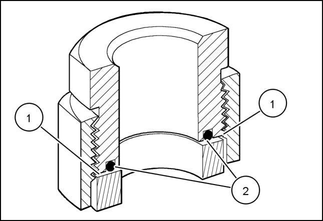
INSTALLATION OF ORFS (O-RING FLAT FACED) FITTINGS
When installing ORFS fittings thoroughly clean both flat surfaces of the fittings (1) and lubricate the O-ring (2) with light oil. Make sure both surfaces are aligned properly. Torque the fitting to specified torque listed throughout the repair manual.
NOTICE: If the fitting surfaces are not properly cleaned, the O-ring will not seal properly. If the fitting surfaces are not properly aligned, the fittings may be damaged and will not seal properly.
NOTICE: Always use genuine factory replacement oils and filters to ensure proper lubrication and filtration of engine and hydraulic system oils.
The use of proper oils, grease, and keeping the hydraulic system clean will extend machine and component life.
INTRODUCTION
PIPE THREAD FITTING Thread Size Torque (Maximum) 1/8-27 13 N·m (10 lb ft) 1/4-18 16 N·m (12 lb ft) 3/8-18 22 N·m (16 lb ft) 1/2-14 41 N·m (30 lb ft) 3/4-14 54 N·m (40 lb ft) 50011183 2 84423866 25/07/2011 21
General specification - Biodiesel Fuels
Fatty Acid Methyl Ester Biodiesel (Biodiesel Fuel) consists of a family of fuels derived from vegetable oils treated with methyl esters.
NOTICE: Biodiesel Fuel blends are approved for your engine only if they comply with EN14214 Specification Standards or ASTM D6751.
NOTICE: It is imperative that you check which blend is approved for your engine with your CASE CONSTRUCTION dealer. Be aware that the use of Biodiesel Fuel that does not comply with the Standards mentioned above could lead to severe damage to the engine and fuel system of your machine. The use of fuels that are not approved may void
CASE CONSTRUCTION Warranty coverage.
Biodiesel Fuel Usage Conditions
NOTICE: The Biodiesel Fuel must meet the fuel Specification mentioned above.
Biodiesel Fuel must be purchased from a trusted supplier that understands the product and maintains good fuel quality. Biodiesel Fuel must be pre-blended by the supplier. Mixing Biodiesel Fuels on-site can result incorrect mixture that can lead to problems with both engine and fuel system.
Engine performance is affected by the use of Biodiesel Fuel. There may be up to 12 % reduction in power or torque depending on the blend used.
NOTICE: DO NOT modify the engine and/or injection pump settings to recover the reduced performance.
The reduced power must be accepted if using any Biodiesel Fuel blend.
Some modification may be required to allow your engine to run Biodiesel Fuel. Consult you dealer for complete information on these modifications.
Biodiesel Fuel has a higher cloud point than Diesel Fuel.
NOTICE: The use of high Biodiesel Fuel blends are not recommended in cold weather conditions.
With Biodiesel Fuels, it may be necessary to change the engine oil, engine oil filter and fuel filter elements more frequently than with Diesel Fuels. Biodiesel Fuel can remove rust and particles from the inside of on-site fuel storage tanks that would normally adhere to the sides of the tank. Like particle deposits that commonly occur with Diesel Fuel, these particles can become trapped by the machine fuel filters, causing blockage and shortening filter life. In cold weather, this is more likely to happen. Consult your CASE CONSTRUCTION dealer for information on cold weather operation and proper maintenance intervals when using any Biodiesel Fuel blend.
When handling Biodiesel Fuel, care must be taken not to allow water into the fuel supply. Biodiesel Fuel will actually attract moisture from the atmosphere.
Fuel tanks must be kept as full as possible to limit the amount of air and water vapors in them. It may be necessary to drain the fuel filter water tap more frequently.
Potential oxidation and stability could be a problem with the fuel stored in the machine.
NOTICE: Machines must not be stored for more than three months with Biodiesel Fuel blends in the fuel system. If long storage periods are necessary, the engine must run on Diesel Fuel for 20 hours to flush the Biodiesel Fuel out of the engine fuel system prior to storage.
NOTICE: Biodiesel Fuel must not be stored in on-site storage tanks for more than three months.
Any spillage of Biodiesel Fuel must be cleaned up immediately before it can cause damage to the environment and the paint finish of the machine.
Before using Biodiesel Fuel blends you should consult with your dealer to receive full information about the approved blend for your machine and any detailed conditions of its usage.
NOTICE: Be aware that not fulfilling the requirements and conditions of Biodiesel Fuel usage will void your machine’s CASE CONSTRUCTION Warranty coverage.
INTRODUCTION
84423866 25/07/2011 22
General specification - General Welding

WARNING
Explosion hazard!
Batteries emit explosive gases. Always ventilate when using in an enclosed area or when charging. Keep the battery away from sparks, open flames, and other ignition sources. Failure to comply could result in death or serious injury.
Use a 7013 or 7011 welding rod or wire that meets the following American Welding Society (AWS) specifications: ER80S-D2, ER70S-6 or E70C-M6-H4.
NOTICE: ALWAYS disconnect the battery (both terminals) before welding on any part of the machine. Failure to do so may cause damage to sensitive electrical components.
NOTICE: Locate the welding ground as close as possible to the area to be welded. Do not allow the ground current to pass through any roller type bearing. Arcing inside the roller bearing can result in severe machine damage.
INTRODUCTION
W0369A
84423866 25/07/2011 23
Consumable IU PAGE Loctite® RTV 598 Basic instructions - Shop and Assembly 13 Loctite® Instant Gasket 587 Blue Basic instructions - Shop and Assembly 13 Loctite® 569 Torque - Standard torque data for hydraulics 20 Loctite® 567 PST Pipe Sealant Torque - Standard torque data for hydraulics 21 Loctite® 565 PST Torque - Standard torque data for hydraulics 21 Loctite® 545 Torque - Standard torque data for hydraulics 21 84423866 25/07/2011 24
CONSUMABLES INDEX

ELECTRICAL,
SERVICE MANUAL HYDRAULIC, PNEUMATIC,
ELECTRONIC SYSTEMS
84423866 25/07/2011 A
SR130 , SR150 , SR175 , SR200 , SR220 , SR250 , SV185 , SV250 , SV300 , TR270 , TR320 , TV380
Contents HYDRAULIC, PNEUMATIC, ELECTRICAL, ELECTRONIC
PRIMARY HYDRAULIC POWER SYSTEM..................................................................................A.10.A SR130 , SR150 , SR175 , SR200 , SR220 , SR250 , SV185 , SV250 , SV300 , TR270 , TR320 , TV380 SECONDARY HYDRAULIC POWER SYSTEM. A.12.A SR130 , SR150 , SR175 , SR200 , SR220 , SR250 , SV185 , SV250 , SV300 , TR270 , TR320 , TV380 HYDRAULIC COMMAND SYSTEM. A.14.A SR130 , SR150 , SR175 , SR200 , SR220 , SR250 , SV185 , SV250 , SV300 , TR270 , TR320 , TV380 HIGH-FLOW HYDRAULIC POWER SYSTEM A.16.A SR130 , SR150 , SR175 , SR200 , SR220 , SR250 , SV185 , SV250 , SV300 , TR270 , TR320 , TV380 ELECTRICAL POWER SYSTEM .......................................................... A.30.A SR130 , SR150 , SR175 , SR200 , SR220 , SR250 , SV185 , SV250 , SV300 , TR270 , TR320 , TV380 LIGHTING SYSTEM........................................................................ A.40.A SR130 , SR150 , SR175 , SR200 , SR220 , SR250 , SV185 , SV250 , SV300 , TR270 , TR320 , TV380 ELECTRONIC SYSTEM A.50.A SR130 , SR150 , SR175 , SR200 , SR220 , SR250 , SV185 , SV250 , SV300 , TR270 , TR320 , TV380 FAULT CODES A.50.A SR130 , SR150 , SR175 , SR200 , SR220 , SR250 , SV185 , SV250 , SV300 , TR270 , TR320 , TV380 84423866 25/07/2011 A
SYSTEMS - A
Consumable IU PAGE CNH MAT3509 Control valve - General specification of Secondary Auxiliary Valve A.10.A / 20 CNH MAT3509 Reservoir - Filling A.10.A / 138 84423866 25/07/2011 A
CONSUMABLES INDEX
84423866 25/07/2011 A
HYDRAULIC, PNEUMATIC, ELECTRICAL, ELECTRONIC SYSTEMS - A PRIMARY HYDRAULIC POWER SYSTEM - 10.A
84423866 25/07/2011 A.10.A / 1
SR130 , SR150 , SR175 , SR200 , SR220 , SR250 , SV185 , SV250 , SV300 , TR270 , TR320 , TV380
FUNCTIONAL DATA
Contents HYDRAULIC, PNEUMATIC, ELECTRICAL, ELECTRONIC SYSTEMS - A PRIMARY HYDRAULIC POWER SYSTEM - 10.A TECHNICAL DATA PRIMARY HYDRAULIC POWER SYSTEM General specification for the 24.9cc Gear Pump................................................................................................. 7 SR175, SV185 General specification of the 24.9cc Gear pump with high flow 12.5cc pump 8 SR175, SV185 General specification of the 34.1cc gear pump 9 SR200, SR220, SR250, SV250, SV300, TR270, TR320, TV380 General specification of the 20.4cc gear pump..................................................................................................10 SR130, SR150 General specification for 34.1cc Front pump with rear pump 23.0cc 11 SR250, SV300, TV380 General specification for the 34.1cc Gear pump with high flow 12.5cc..........................................................12 SR200, TR270 General specification for the 34.1cc Gear pump with high flow 18.3cc. 13 SR220, SR250, SV250, SV300, TR320, TV380 Filter General specification Hydraulic oil return filter...................................................................................................14 General specification Hydraulic oil supply strainer 15 Control valve General specification of the Ride / Glide Control Valve 16 General specification of the EH Control Loader Valve for all models 17 General specification Mechanical Hand Control Loader valve on all models................................................18 SR130, SR150, SR175, SV185, SR200 General specification of the EH and Mechanical boom override valve on all models 19 General specification of Secondary Auxiliary Valve 20 General specification High Flow Valve ...............................................................................................................20
PRIMARY HYDRAULIC POWER SYSTEM Overview of Contaminates....................................................................................................................................21 Overview EH Drive Pattern Selector Switch 22 SR130 Electro hydraulic controls, SR150 Electro hydraulic controls, SR175 Electro hydraulic controls, SV185 Electro hydraulic controls, SR200 Electro hydraulic controls, SR220 Electro hydraulic controls, SR250 Electro hydraulic controls, SV250 Electro hydraulic controls, SV300 Electro hydraulic controls, TR270 Electro hydraulic controls, TR320 Electro hydraulic controls, TV380 Electro hydraulic controls Component identification of hydraulic valves 23 SR220, SR250, SV250, SV300, TR320, TV380 84423866 25/07/2011 A.10.A / 2
Component identification of hydraulic valves on medium frame models........................................................31 SR175, SV185, SR200, TR270 Component identification of hydraulic valves 41 SR130, SR150 Component identification of pumps on large frame models 44 SR220, SR250, SV250, SV300, TR320, TV380 Component identification of pumps on medium frame models........................................................................48 SR175, SV185, SR200, TR270 Component identification of pumps on small frame models 52 SR130, SR150 Component identification of cylinders on small frame models.........................................................................53 SR130, SR150 Component identification of cylinders on medium frames 54 SR175, SV185, SR200, TR270 Component identification of cylinders on large frame models 59 SR220, SR250, SV250, SV300, TR320, TV380 Component identification of hydraulic motors 62 SR220, SR250, SV250, SV300, TR320, TV380 Component identification of hydraulic motors 64 SR175, SV185, SR200, TR270 Component identification of hydraulic motors on small frame models............................................................66 SR130, SR150 Hydraulic schematic frame 01 Two speed drive assembly 68 SV185 Electro hydraulic controls, SR220 Electro hydraulic controls, SR250 Electro hydraulic controls, SV250 Electro hydraulic controls, SV300 Electro hydraulic controls Hydraulic schematic frame 02 Single speed drive assembly 70 SR220 Mechanical hydraulic controls, SR250 Mechanical hydraulic controls, SV250 Mechanical hydraulic controls, SV300 Mechanical hydraulic controls, TR320 Mechanical hydraulic controls, TV380 Mechanical hydraulic controls Hydraulic schematic frame 03 Valve assembly 72 SR220 Mechanical hydraulic controls, SR250 Mechanical hydraulic controls, SV250 Mechanical hydraulic controls, SV300 Mechanical hydraulic controls, TR320 Mechanical hydraulic controls, TV380 Mechanical hydraulic controls Hydraulic schematic frame 04 Enhanced high flow option 74 SR220 Electro hydraulic controls, SR250 Electro hydraulic controls, SV250 Electro hydraulic controls, SV300 Electro hydraulic controls, TR320 Electro hydraulic controls, TV380 Electro hydraulic controls Hydraulic schematic frame 01 Two speed drive assembly 76 SR175 Mechanical hydraulic controls, SV185 Mechanical hydraulic controls, SR200 Mechanical hydraulic controls Hydraulic schematic frame 02 Single speed drive assembly...........................................................................78 SR130 Mechanical hydraulic controls, SR150 Mechanical hydraulic controls, SR175 Mechanical hydraulic controls, SV185 Mechanical hydraulic controls, SR200 Mechanical hydraulic controls Hydraulic schematic frame 03 Valve assembly...................................................................................................80 SR130 Mechanical hydraulic controls, SR150 Mechanical hydraulic controls, SR175 Mechanical hydraulic controls, SV185 Mechanical hydraulic controls, SR200 Mechanical hydraulic controls Hydraulic schematic frame 01 Two speed track drive assembly 82 TR270 Electro hydraulic controls, TR320 Electro hydraulic controls, TV380 Electro hydraulic controls Hydraulic schematic frame 02 Valve assembly 84 SR220 Electro hydraulic controls, SR250 Electro hydraulic controls, SV250 Electro hydraulic controls, SV300 Electro hydraulic controls, TR270 Electro hydraulic controls, TR320 Electro hydraulic controls, TV380 Electro hydraulic controls Hydraulic schematic frame 03 Enhanced high flow option 86 SV185 Electro hydraulic controls, SR220 Electro hydraulic controls, SR250 Electro hydraulic controls, SV250 Electro hydraulic controls, SV300 Electro hydraulic controls, TR270 Electro hydraulic controls, TR320 Electro hydraulic controls, TV380 Electro hydraulic controls Hydraulic schematic frame 01 Two speed drive assembly...............................................................................88 SR220, SR250, SV250, SV300 Hydraulic schematic frame 02 Valve assembly 90 SR220 Electro hydraulic controls, SR250 Electro hydraulic controls, SV250 Electro hydraulic controls, SV300 Electro hydraulic controls, TR270 Electro hydraulic controls, TR320 Electro hydraulic controls, TV380 Electro hydraulic controls 84423866 25/07/2011 A.10.A / 3
Hydraulic schematic frame 03 Enhanced high flow option...............................................................................92 SV185 Electro hydraulic controls, SR220 Electro hydraulic controls, SR250 Electro hydraulic controls, SV250 Electro hydraulic controls, SV300 Electro hydraulic controls, TR270 Electro hydraulic controls, TR320 Electro hydraulic controls, TV380 Electro hydraulic controls Hydraulic schematic frame 01 Two speed drive assembly 94 SR175 Electro hydraulic controls, SV185 Electro hydraulic controls, SR200 Electro hydraulic controls Hydraulic schematic frame 02 Single speed drive assembly 96 SR175 Mechanical hydraulic controls, SV185 Mechanical hydraulic controls, SR200 Mechanical hydraulic controls Hydraulic schematic frame 03 Valve assembly 98 SR175 Electro hydraulic controls, SV185 Electro hydraulic controls, SR200 Electro hydraulic controls Hydraulic schematic frame 01 Single speed drive assembly 100 SR130 Mechanical hydraulic controls, SR150 Mechanical hydraulic controls Hydraulic schematic frame 02 Valve assembly.................................................................................................102 SR130 Mechanical hydraulic controls, SR150 Mechanical hydraulic controls Hydraulic schematic frame 01 Single speed drive assembly 104 SR130 Electro hydraulic controls, SR150 Electro hydraulic controls Hydraulic schematic frame 02 Valve assembly.................................................................................................106 SR130 Electro hydraulic controls, SR150 Electro hydraulic controls Hydraulic schematic frame 01 Mechanical two speed track drive assembly 108 TR270 Mechanical hydraulic controls, TR320 Mechanical hydraulic controls, TV380 Mechanical hydraulic controls Hydraulic schematic frame 02 Valve assembly 110 TR270 Mechanical hydraulic controls, TR320 Mechanical hydraulic controls, TV380 Mechanical hydraulic controls Control valve Overview Loader Lift Control - Overview 113 Overview Loader bucket control ........................................................................................................................114 Overview Loader arm float 115 SERVICE PRIMARY HYDRAULIC POWER SYSTEM Cleaning 116 Decontaminating 119 Depressurising 121 Relief valve Flow test Loader main relief valve .....................................................................................................................122 Pressure test Loader valve main relief..............................................................................................................124 Hydraulic pump Flow test Loader hydraulic pump....................................................................................................................... 125 Install.....................................................................................................................................................................127 Charge pump Pressure test ........................................................................................................................................................131 Pressure test (Machines Equipped with EH Controls) 134 Reservoir Apply vacuum.......................................................................................................................................................137 Filling 138 Visual inspection 139 Filter Remove 140 Install 141 Oil cooler 84423866 25/07/2011 A.10.A / 4
Remove for models equipped with ISM engine................................................................................................142 SR130, SR150, SR175, SV185 Install for machines equipped with ISM engine 145 SR130, SR150, SR175, SV185 Remove - for machines equipped with F5C engine 148 SR200, SR220, SR250, SV250, SV300 Install - for machines equipped with F5C engine.............................................................................................151 SR200, SR220, SR250, SV250, SV300, TR270, TR320, TV380 84423866 25/07/2011 A.10.A / 5
PRINTED IN U.S.A.
© 2011 CNH America LLC.
All rights reserved. No part of the text or illustrations of this publication may be reproduced.
CASE CONSTRUCTION policy is one of continuous improvement and the right to change prices, specification or equipment at any time without notices is reserved.
All data given in this publication is subject to production variations. Dimensions and weight are approximate only and the illustrations do not necessarily show products in standard condition. For exact information about any particular product, please consult your CASE CONSTRUCTION Dealer.
New Holland Site 100 Brubaker Avenue New Holland, Pennsylvania United States 17557
SERVICE - Technical Publications & Tools
84423866 25/07/2011 EN
AND PTO IN
SERVICE MANUAL ENGINE
84423866 25/07/2011 B
SR130 , SR150 , SR175 , SR200 , SR220 , SR250 , SV185 , SV250 , SV300 , TR270 , TR320 , TV380
Contents
ENGINE..............................................................................................................................................B.10.A SR130 , SR150 , SR175 , SR200 , SR220 , SR250 , SV185 , SV250 , SV300 , TR270 , TR320 , TV380 FUEL AND INJECTION SYSTEM.......................................................... B.20.A SR130 , SR150 , SR175 , SR200 , SR220 , SR250 , SV185 , SV250 , SV300 , TR270 , TR320 , TV380 AIR INTAKE SYSTEM B.30.A SR130 , SR150 , SR175 , SR200 , SR220 , SR250 , SV185 , SV250 , SV300 , TR270 , TR320 , TV380 ENGINE COOLANT SYSTEM B.50.A SR130 , SR150 , SR175 , SR200 , SR220 , SR250 , SV185 , SV250 , SV300 , TR270 , TR320 , TV380 STARTING SYSTEM B.80.A SR130 , SR150 , SR175 , SR200 , SR220 , SR250 , SV185 , SV250 , SV300 , TR270 , TR320 , TV380 84423866 25/07/2011 B
ENGINE AND PTO IN - B
ENGINE AND PTO IN - B ENGINE - 10.A
84423866 25/07/2011 B.10.A / 1
SR130 , SR150 , SR175 , SR200 , SR220 , SR250 , SV185 , SV250 , SV300 , TR270 , TR320 , TV380
Contents ENGINE AND PTO IN - B ENGINE - 10.A SERVICE ENGINE Remove 3 SR130, SR150, SR175, SV185 Remove...................................................................................................................................................................12 SR200, SR220, SR250, SV250, SV300, TR270, TR320, TV380 Install 22 SR130, SR150, SR175, SV185 Install 30 SR200, SR220, SR250, SV250, SV300, TR270, TR320, TV380 84423866 25/07/2011 B.10.A / 2
ENGINE - Remove
SR130, SR150, SR175, SV185
WARNING
Avoid injury! Always do the following before lubricating, maintaining, or servicing the machine.
1. Disengage all drives.
2. Engage parking brake.
3. Lower all attachments to the ground, or raise and engage all safety locks.
4. Shut off engine.
5. Remove key from key switch.
6. Switch off battery key, if installed.
7. Wait for all machine movement to stop.
Failure to comply could result in death or serious injury.
WARNING
Fire hazard!
When handling diesel fuel, observe the following precautions:
1. Do not smoke.
2. Never fill the tank when the engine is running.
3. Wipe up spilled fuel immediately.
Failure to comply could result in death or serious injury.
WARNING
Escaping fluid!
Hydraulic fluid or diesel fuel leaking under pressure can penetrate the skin and cause infection or other injury. To prevent personal injury: Relieve all pressure before disconnecting fluid lines or performing work on the hydraulic system. Before applying pressure, make sure all connections are tight and all components are in good condition. Never use your hand to check for suspected leaks under pressure. Use a piece of cardboard or wood for this purpose. If injured by leaking fluid, see your doctor immediately.
Failure to comply could result in death or serious injury. W0178A
WARNING
Heavy objects!
Lift and handle all heavy components using lifting equipment with adequate capacity. Always support units or parts with suitable slings or hooks. Make sure the work area is clear of all bystanders. Failure to comply could result in death or serious injury. W0398A
Prior operation:
Tilt system - Tilt (E.34.A)
Prior operation:
Battery - Disconnect (A.30.A)
W0047A
W0099A
ENGINE AND PTO IN - ENGINE
84423866 25/07/2011 B.10.A / 3
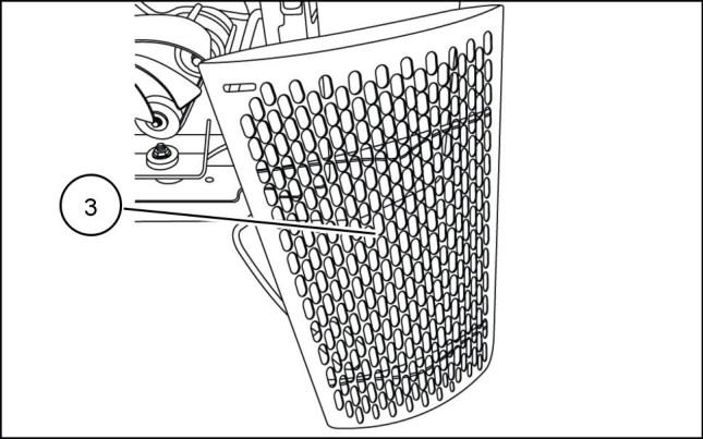
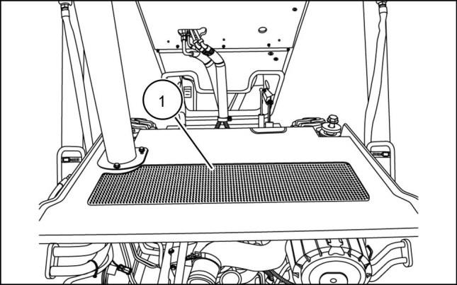
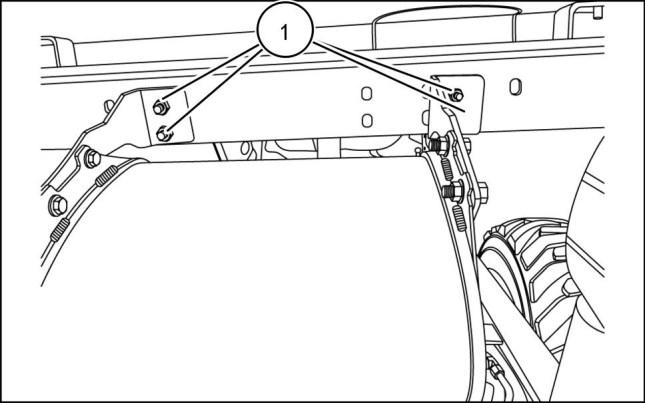
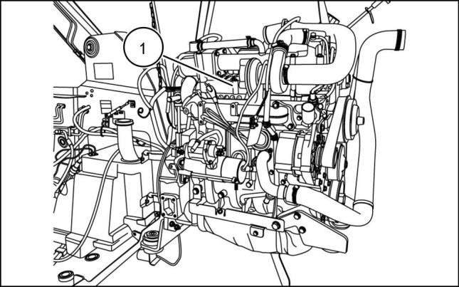
1. Remove the hood strut (1) from hood

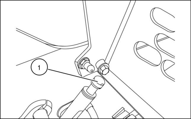
2. Remove hood mounting hardware (2) from left and right hand side
3. Remove the hood (3)
4. Remove the rear access door refer to Engine hood - Remove (E.20.A)
5. Drain the engine oil.
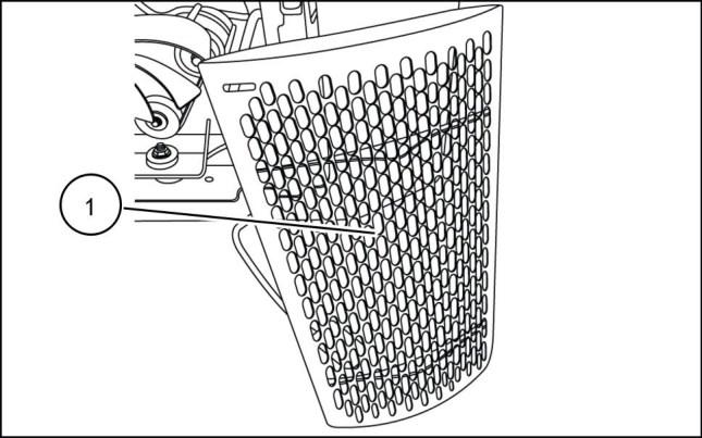
6. Remove the radiator refer to Radiator - Remove (B.50.A)
7. Remove the oil cooler refer to Oil cooler - Remove (A.10.A)
ENGINE AND PTO IN - ENGINE
931001682 1 931002025 2 931002026 3 84423866 25/07/2011 B.10.A / 4


ENGINE AND PTO IN - ENGINE
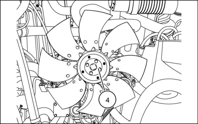
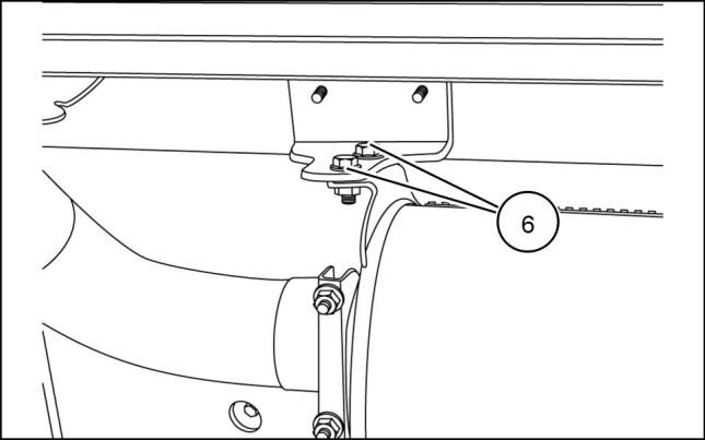
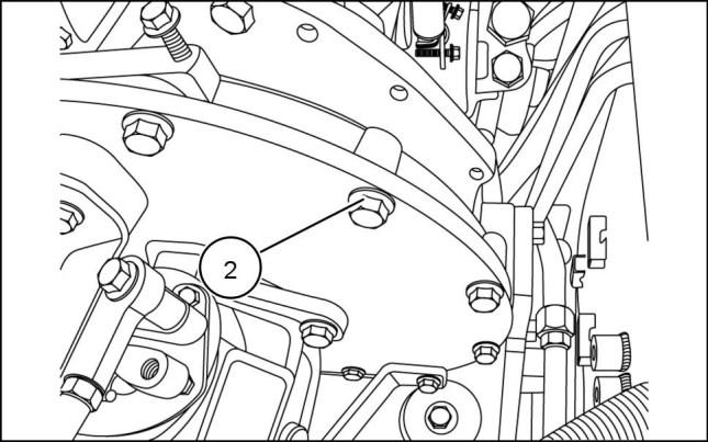
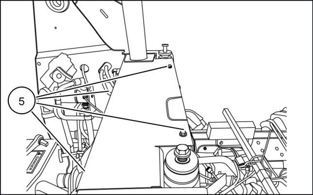
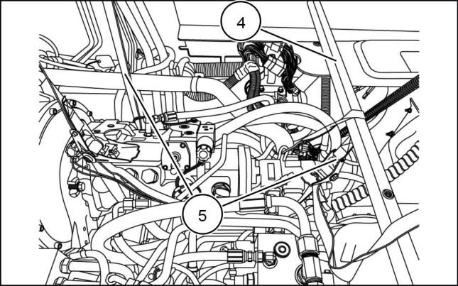
8. Remove the four mounting bolts (4) and slide the fan off the hub.
9. Remove the five mounting bolts (5) retaining the muffler inlet pipe mounting flange to the turbocharger and remove muffler.
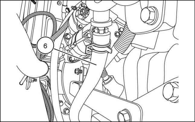
10. Remove the two retaining bolts (6) from the muffler support.
931002027 4 931002028 5 931002029 6 931002030 7 84423866 25/07/2011 B.10.A / 5
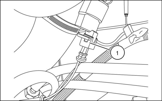
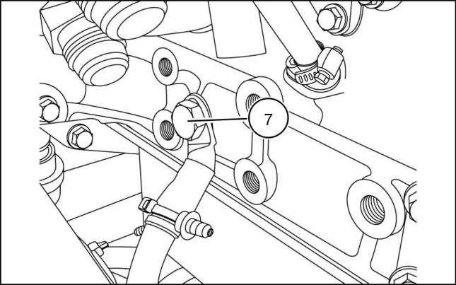
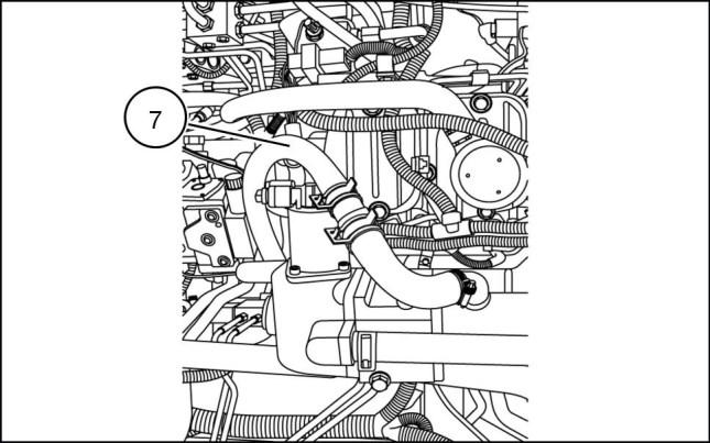
11. Disconnect air restriction sensor (7)
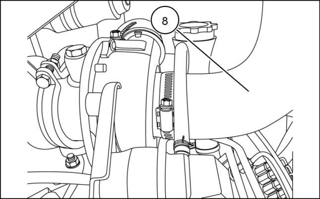
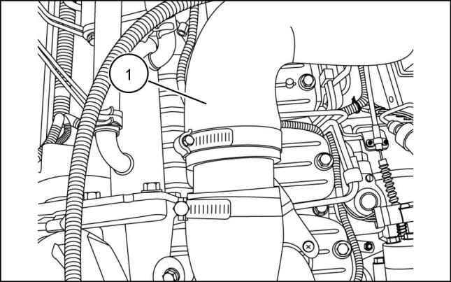
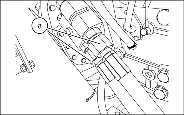
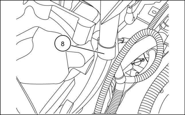
12. Loosen the hose clamps on the intake tube at both ends, remove the intake tube (8), cover turbocharger inlet to avoid entry of debris.
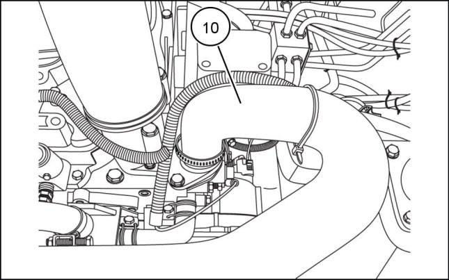
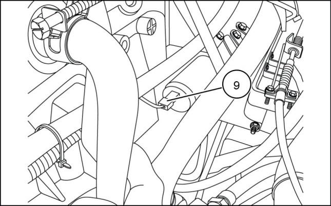
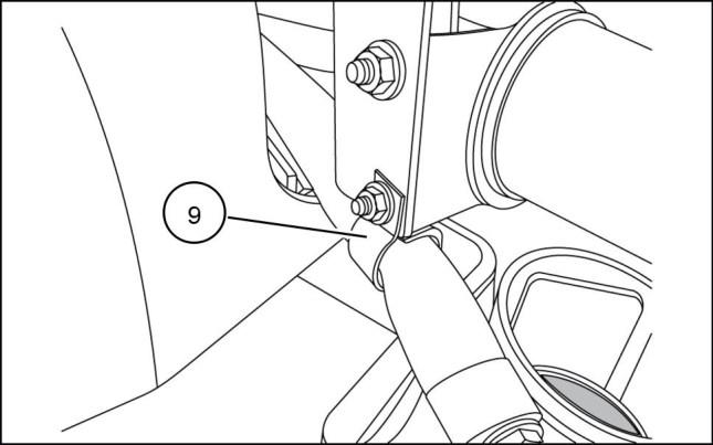
13. Remove air cleaner housing (9)
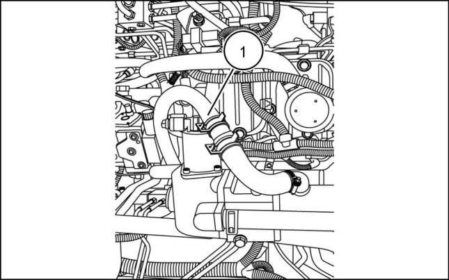
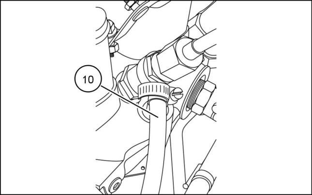
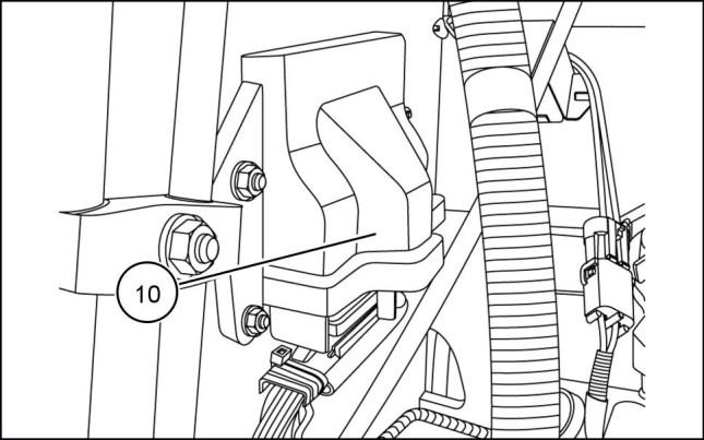
14. Loosen hose clamp and remove upper radiator hose (10) from engine.
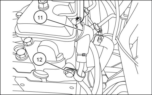
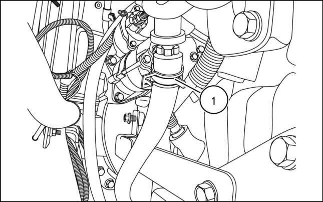
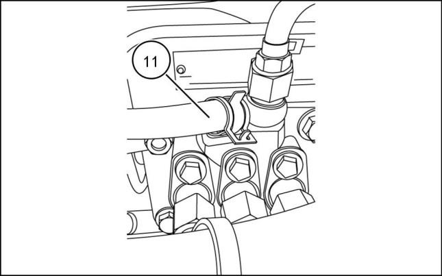
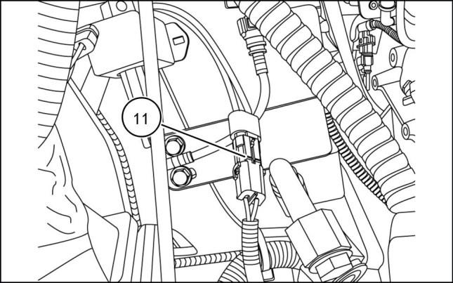
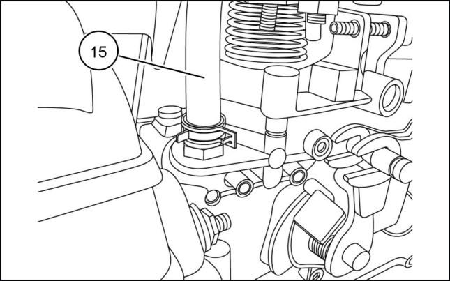
15. Disconnect the glow plug connection (11) Remove wire clamp (12)
ENGINE AND PTO IN - ENGINE
931002031 8 931002032 9 931002033 10 931002034 11 84423866 25/07/2011 B.10.A / 6
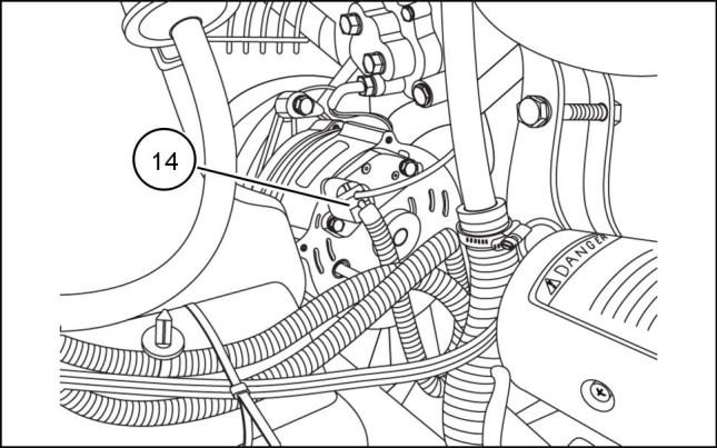
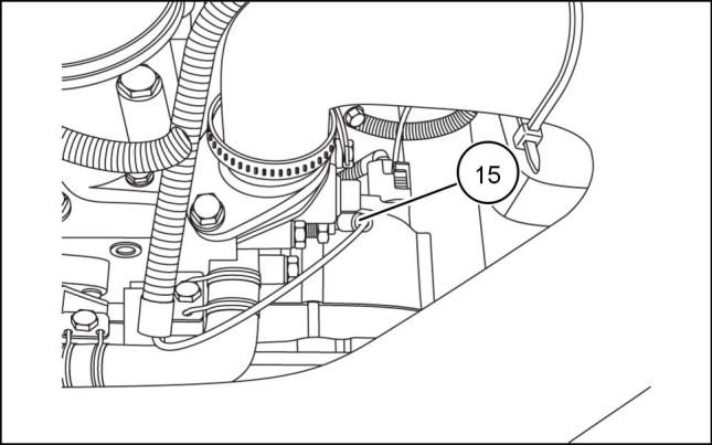
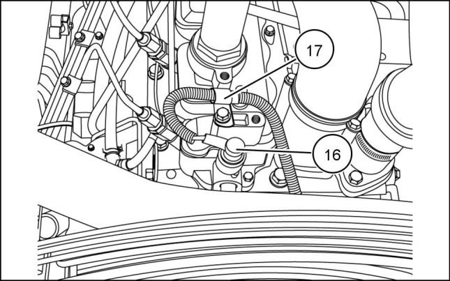
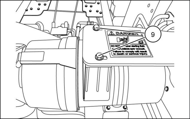
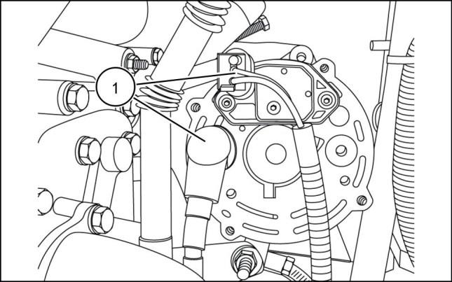
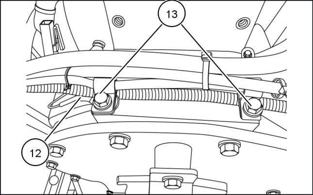
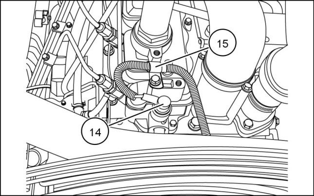
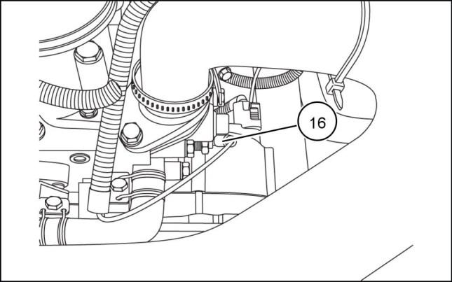
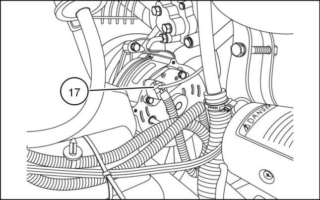
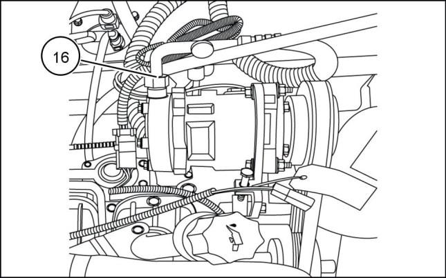
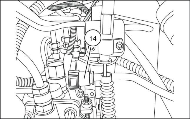
ENGINE AND PTO IN - ENGINE 16. Disconnect the starter connections (13) 17. Disconnect the alternator connection (14) 18. Disconnect temperature sender wire (15) 19. Disconnect oil pressure sender wire (16) and wire clamp (17) 931002035 12 931002036 13 931002037 14 931002038 15 84423866 25/07/2011 B.10.A / 7
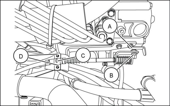
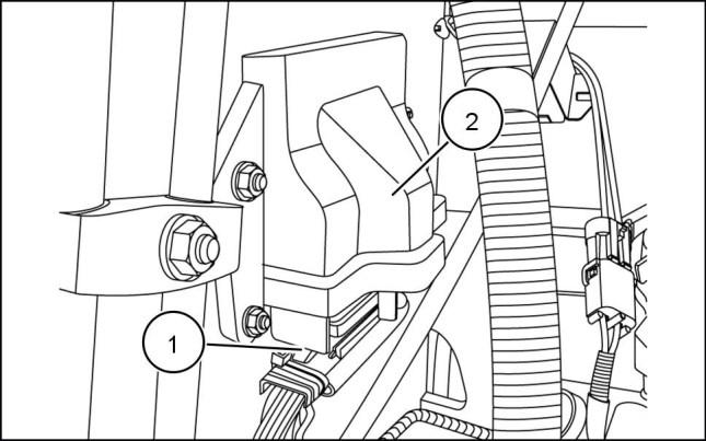
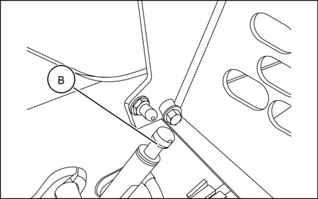
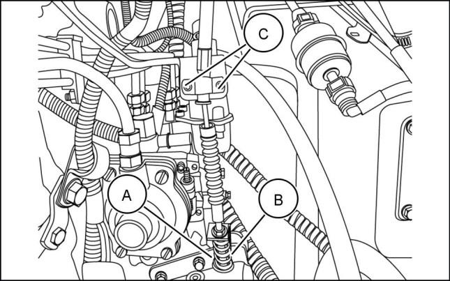
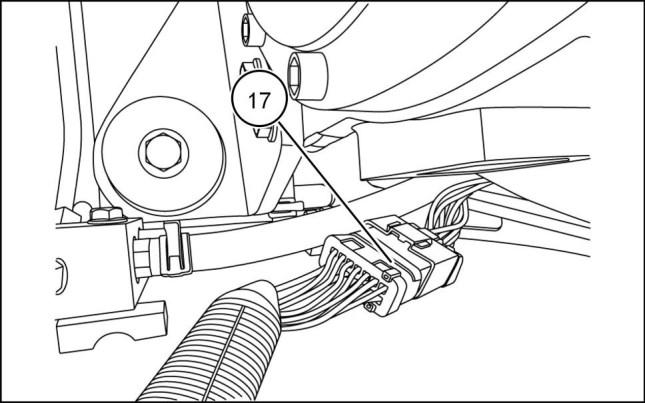
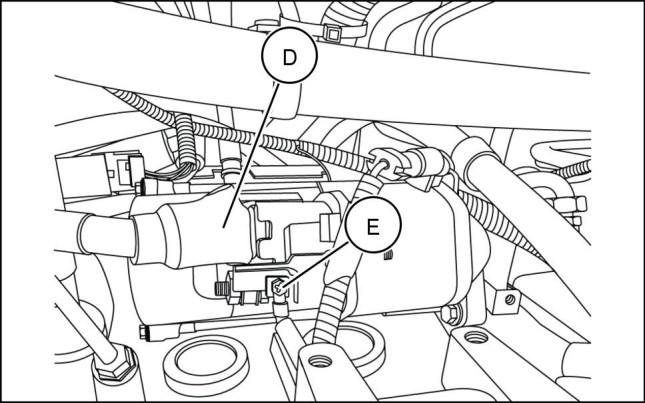
20. Disconnect throttle cable by removing the nut (A)and bolt (B) from the throttle body. Remove cable support clamp (C) by loosening the two hex head bolts (D)
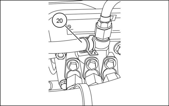
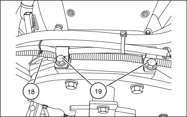
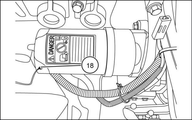
21. Disconnect wire harness (18) and clamps (19) from the top of the flywheel housing.
22. WARNING
Fire hazard!
When handling diesel fuel, observe the following precautions:
1. Do not smoke.
2. Never fill the tank when the engine is running.
3. Wipe up spilled fuel immediately. Failure to comply could result in death or serious injury.
WARNING
Escaping fluid!
Hydraulic fluid or diesel fuel leaking under pressure can penetrate the skin and cause infection or other injury. To prevent personal injury: Relieve all pressure before disconnecting fluid lines or performing work on the hydraulic system. Before applying pressure, make sure all connections are tight and all components are in good condition. Never use your hand to check for suspected leaks under pressure. Use a piece of cardboard or wood for this purpose. If injured by leaking fluid, see your doctor immediately. Failure to comply could result in death or serious injury.
W0178A
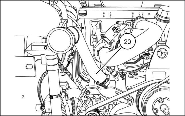
Place a suitable container under lines to prevent spillage and remove the fuel supply line (20).
ENGINE AND PTO IN - ENGINE
931002039 16 931002040 17
W0099A 931002042 18
84423866 25/07/2011 B.10.A / 8
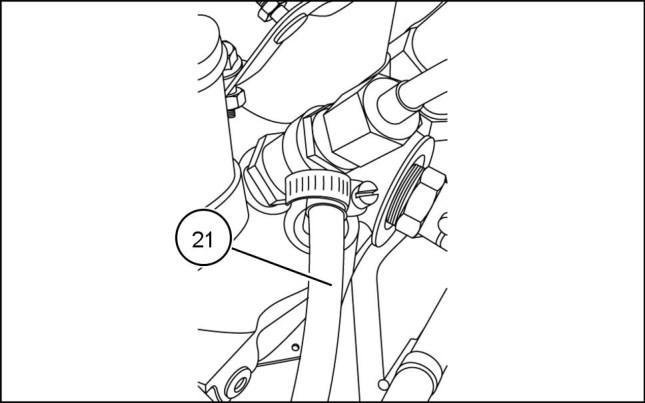
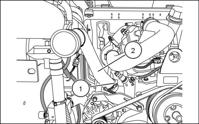
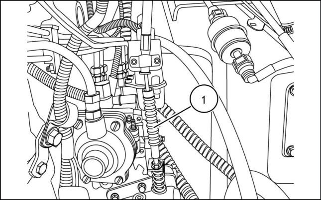
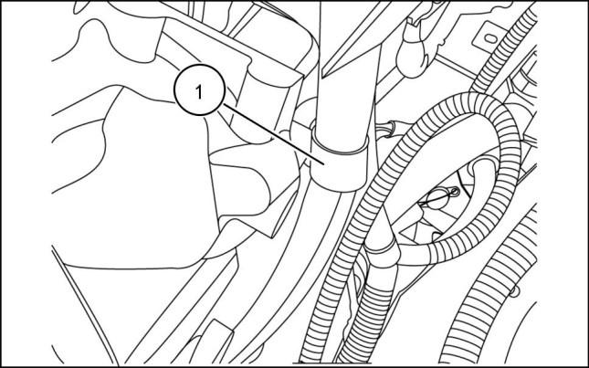
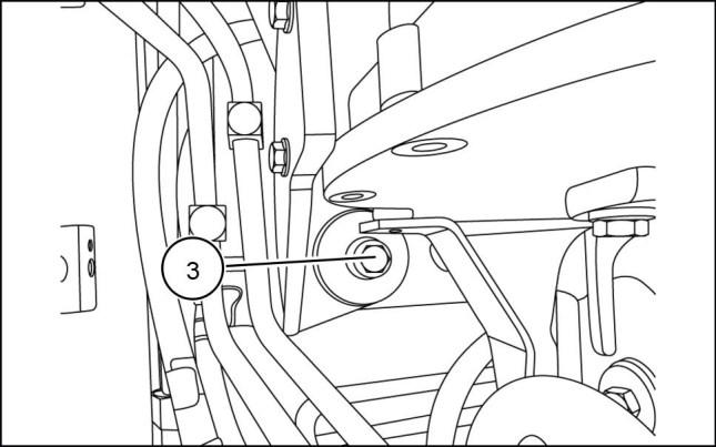
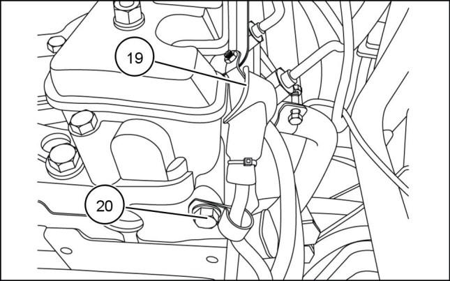
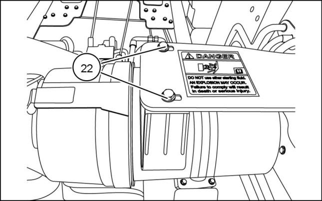
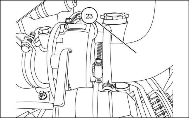
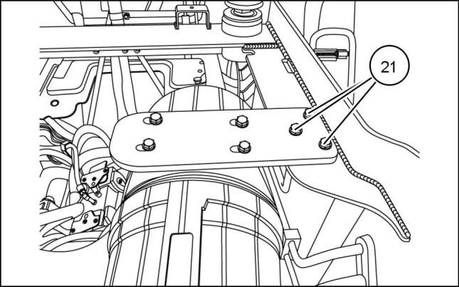
23. Remove the fuel return line (21)
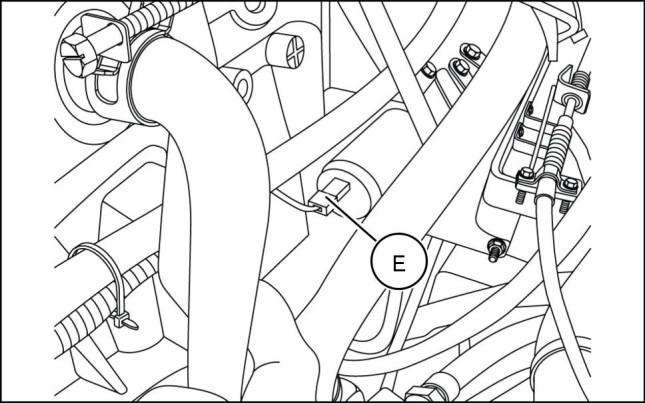
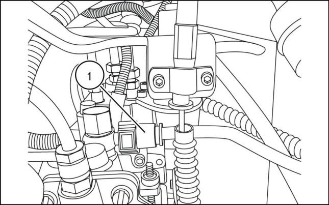
Disconnect
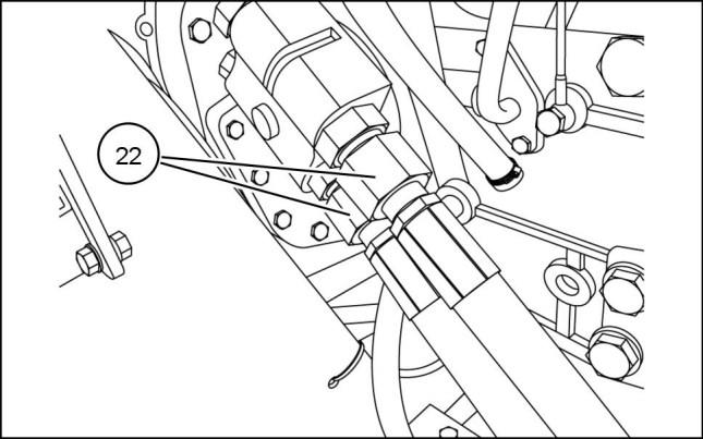
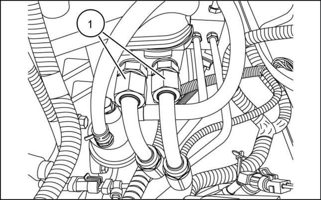
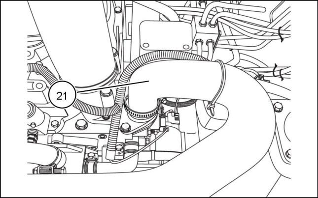
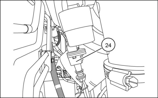
25. Place a suitable container under the remote engine oilfilterlines. Labelanddisconnectoilfilterlines(22)
NOTE: Cap the ends to avoid entry of debris.
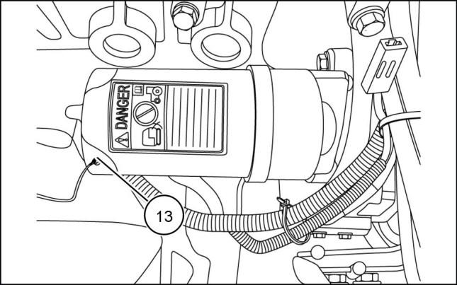
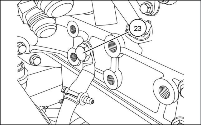
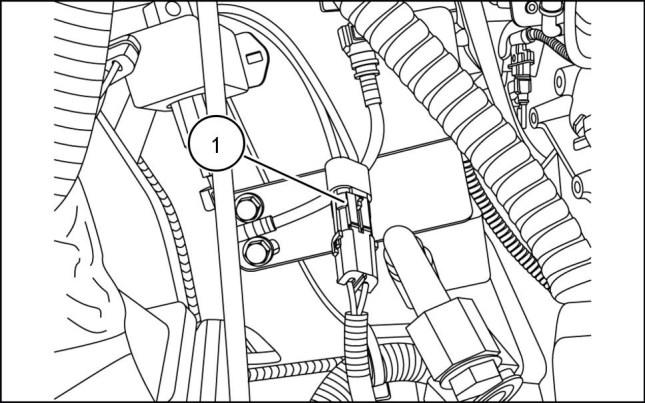
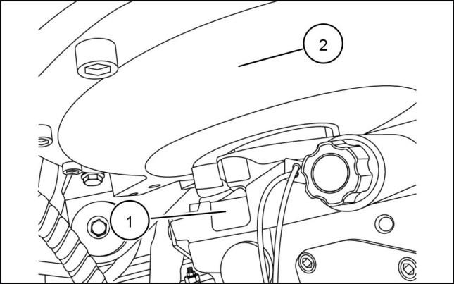
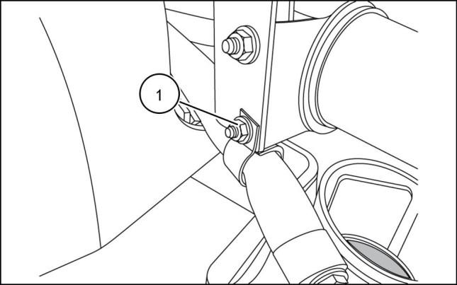
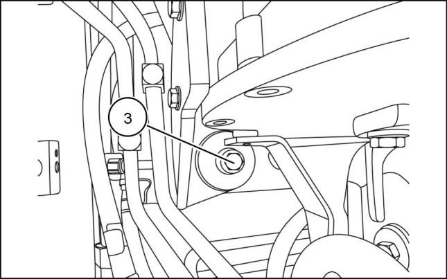
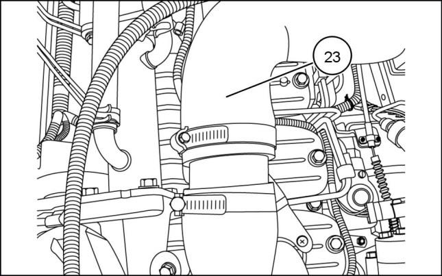
26. Disconnect the ground from the engine (23) to the battery quick disconnect.
ENGINE AND PTO IN - ENGINE
24.
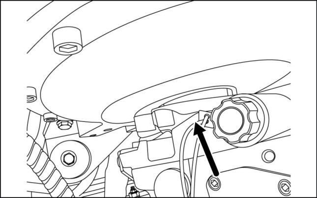
the spade connector (E)from the back side of the fuel shut off solenoid.
931002041 19 931002043 20 931002044 21 931002045 22 84423866 25/07/2011 B.10.A / 9
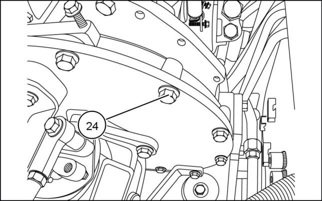
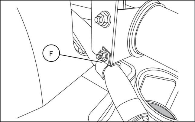
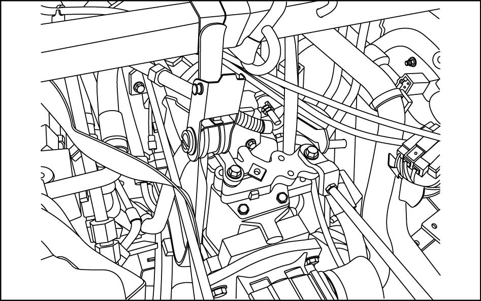
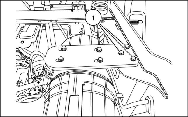
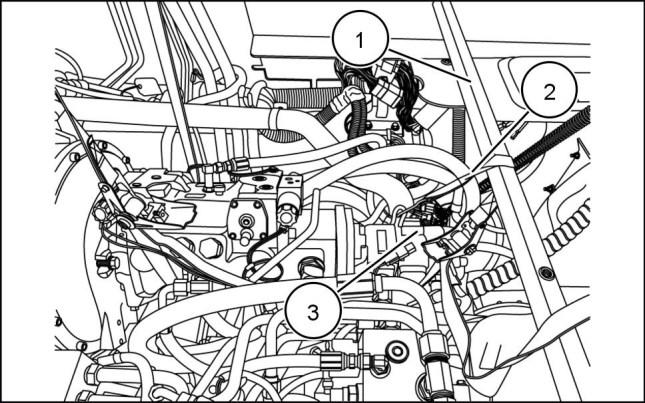
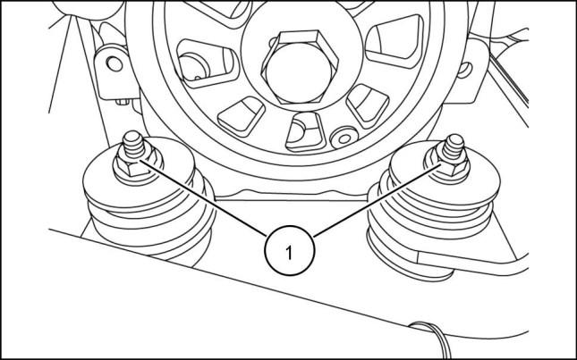
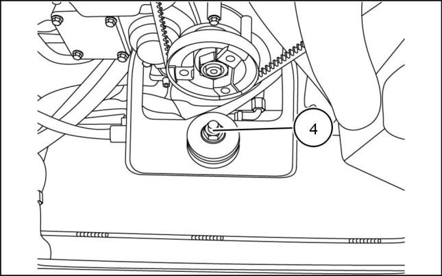
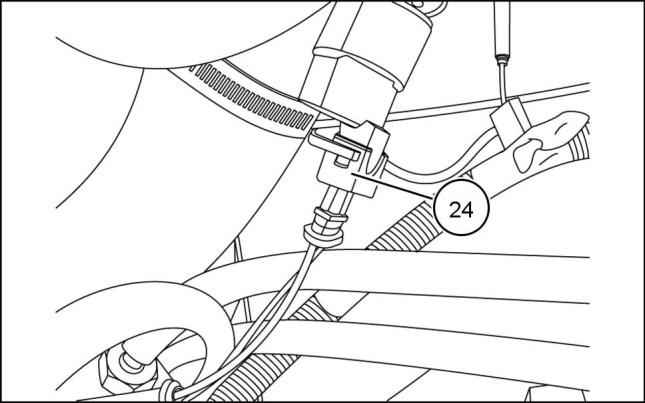
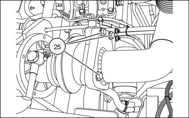
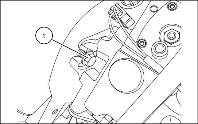
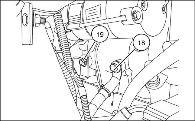
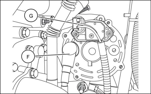
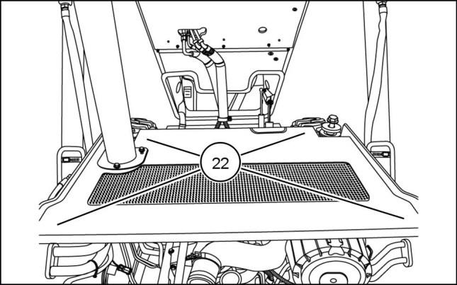
27. Remove the twelve mounting bolts (24) securing the hydraulic pump to the engine plate
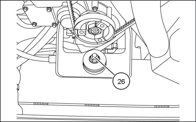
28. Remove engine oil pan drain hose clamp (F)
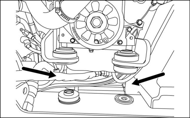
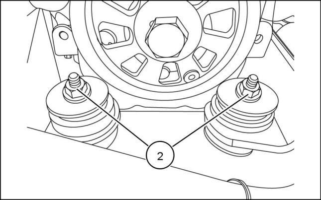
29. Remove the front engine mounts (25)
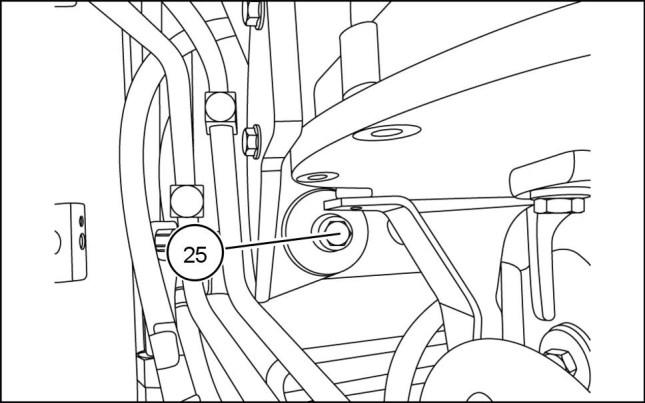
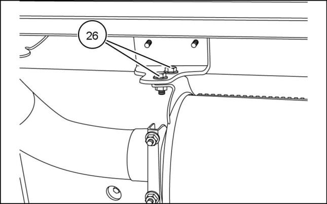
30. Remove the rear engine mount (26)
ENGINE AND PTO IN - ENGINE
931002046 23 931002050 24 931002047 25 931002048 26 84423866 25/07/2011 B.10.A / 10
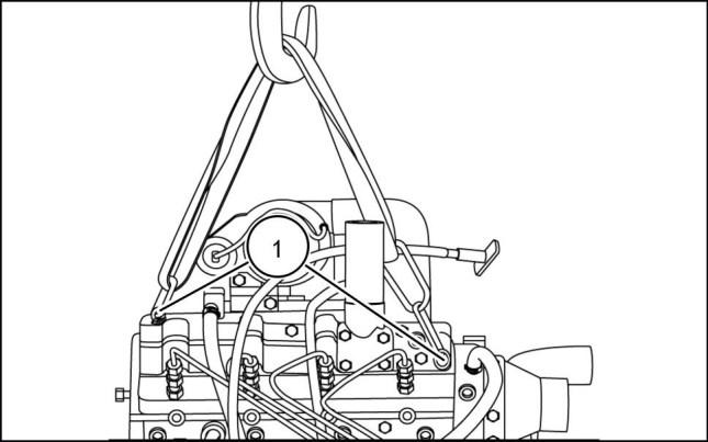
33. DANGER
Heavy parts! Support designated component(s) with adequate lifting equipment. Failure to comply will result in death or serious injury.
Attach
ENGINE AND PTO IN - ENGINE
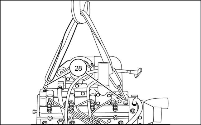
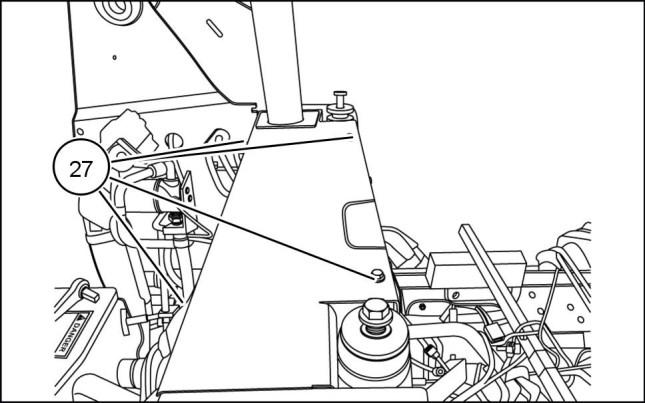
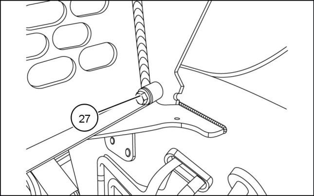
31. Remove the four mounting bolts (27) from the fixed hood, remove hood.
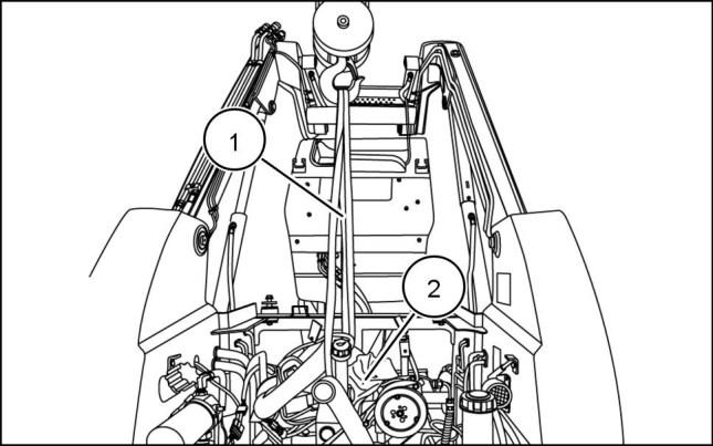
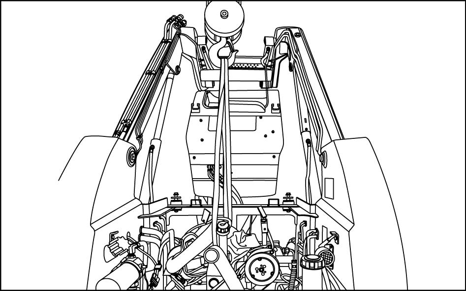
32. Place a suitable support beam across the skid steer frame. Tie a suitable strap around the pump and secure to the support beam, as shown.
931002049 27 931002051 28 D0018A
proper lifting straps to the eye hooks (28) provided on the engine.
931002052 29 931002053 30 84423866 25/07/2011 B.10.A / 11
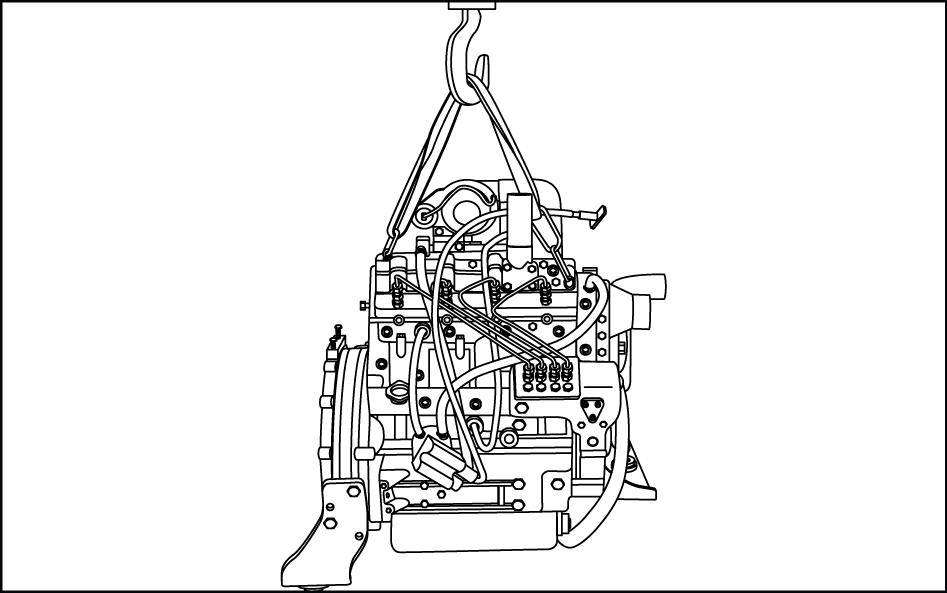
34. Use a suitable hoist to carefully lift the engine slightly rearward to separate from the hydraulic pumps. Once free, lift the engine and remove from the rear of chassis.
ENGINE - Remove
SR200, SR220, SR250, SV250, SV300, TR270, TR320, TV380
WARNING
Avoid injury! Always do the following before lubricating, maintaining, or servicing the machine.
1. Disengage all drives.
2. Engage parking brake.
3. Lower all attachments to the ground, or raise and engage all safety locks.
4. Shut off engine.
5. Remove key from key switch.
6. Switch off battery key, if installed.
7. Wait for all machine movement to stop.
Failure to comply could result in death or serious injury. W0047A
WARNING
Fire hazard!
When handling diesel fuel, observe the following precautions:
1. Do not smoke.
2. Never fill the tank when the engine is running.
3. Wipe up spilled fuel immediately.
Failure to comply could result in death or serious injury. W0099A
WARNING
Escaping fluid!
Hydraulic fluid or diesel fuel leaking under pressure can penetrate the skin and cause infection or other injury. To prevent personal injury: Relieve all pressure before disconnecting fluid lines or performing work on the hydraulic system. Before applying pressure, make sure all connections are tight and all components are in good condition. Never use your hand to check for suspected leaks under pressure. Use a piece of cardboard or wood for this purpose. If injured by leaking fluid, see your doctor immediately.
Failure to comply could result in death or serious injury.
WARNING
Heavy objects!
W0178A
Lift and handle all heavy components using lifting equipment with adequate capacity. Always support units or parts with suitable slings or hooks. Make sure the work area is clear of all bystanders. Failure to comply could result in death or serious injury.
W0398A
Prior operation:
Tilt system - Tilt (E.34.A)
Prior operation:
Battery - Disconnect (A.30.A)
Prior operation:
Radiator - Remove (B.50.A)
ENGINE AND PTO IN - ENGINE
84423866 25/07/2011 B.10.A / 12
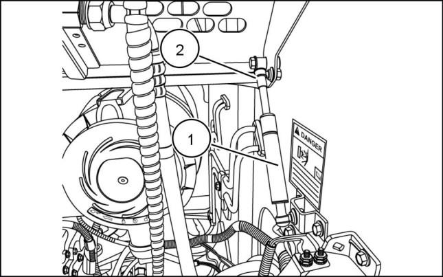
1. Remove the hood struts (1) from each side by gently prying the retaining clip (2) just enough to release the strut.
2. Remove hood mounting hardware (1) from left-hand and right-hand side of the hood.
3. Remove the hood (1)
4. Remove the rear access door refer to Engine hood - Remove (E.20.A)
5. Remove the oil cooler refer to Oil cooler - Remove (A.10.A)
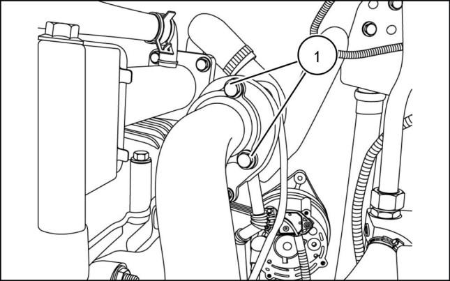
6. Remove the three mounting bolts (1) retaining the muffler inlet pipe mounting flange to the turbocharger, cover turbocharger inlet the avoid entry of debris.
ENGINE AND PTO IN - ENGINE
931001887 1 931002025 2 931002026 3 931001896 4 84423866 25/07/2011 B.10.A / 13
8. Disconnect air restriction sensor (1)
9. Loosen the hose clamps on the intake tube at both ends, remove the air cleaner to turbo charger tube (1)
10. Remove the engine cover (1)
ENGINE AND PTO IN - ENGINE
7. Remove the four retaining bolts (1) from the muffler support.
931001895 5 931002030 6 931001898 7 931001899 8 84423866 25/07/2011 B.10.A / 14
ENGINE AND PTO IN - ENGINE
11. Remove air cleaner housing (1) by removing the three bolts (2)
12. Loosen hose clamp (1) and remove upper radiator hose (2) from engine.
13. Disconnect the alternator electrical connections (1)
931001900 9 931001903 10 931001908 11 931001909 12 84423866 25/07/2011 B.10.A / 15
14. Disconnect the starter electrical connections (1)
15. Disconnect ground connection (1) below the starter (2)
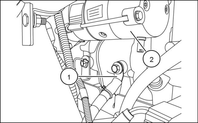
16. Unplug wire harness connection (1)
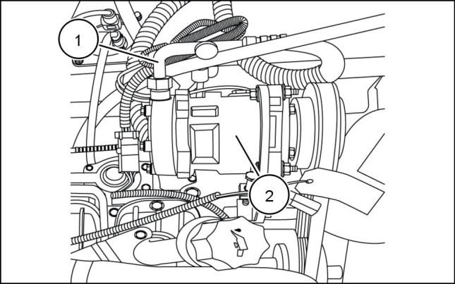
17. Disconnect low pressure line (1) from the Air-conditioning compressor (2)
NOTE: Place a suitable container under the machine to catch any lost fuel.
ENGINE AND PTO IN - ENGINE
931001910 13 931001911 14
931002113 15 84423866 25/07/2011 B.10.A / 16
WARNING
Fire hazard!
When handling diesel fuel, observe the following precautions:
1. Do not smoke.
2. Never fill the tank when the engine is running.
3. Wipe up spilled fuel immediately. Failure to comply could result in death or serious injury.
W0099A
WARNING
Hydraulic fluid or diesel fuel leaking under pressure can penetrate the skin and cause infection or other injury. To prevent personal injury: Relieve all pressure before disconnecting fluid lines or performing work on the hydraulic system. Before applying pressure, make sure all connections are tight and all components are in good condition. Never use your hand to check for suspected leaks under pressure. Use a piece of cardboard or wood for this purpose. If injured by leaking fluid, see your doctor immediately. Failure to comply could result in death or serious injury. W0178A Remove the fuel return line (1)
19. Remove the fuel supply line (1)

931001919 17 931001922 18 84423866 25/07/2011 B.10.A / 17
ENGINE AND PTO IN - ENGINE 18.
Escaping fluid! 931001917 16
20. Remove the throttle cable (1)
ENGINE AND PTO IN - ENGINE
21. Place a suitable container under the remote engine oil filter lines (1) Label and disconnect oil filter lines.
22. Remove the twelve mounting bolts (24) securing the hydraulic pump to the engine plate
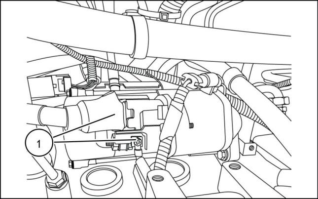
23. Disconnect fuel pump electrical connection (1)
931001923 19 931002046 20 931001925 21 931001926 22 84423866 25/07/2011 B.10.A / 18
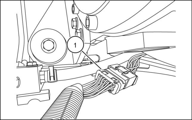
24. Disconnect harness (1) from connector (2)
Heavy parts!
Support designated component(s) with adequate lifting equipment. Failure to comply will result in death or serious injury.
D0018A
Attach proper lifting straps (1) to support the engine (2)

ENGINE AND PTO IN - ENGINE
25. Place a suitable support beam (1) across the skid steer frame. Tie a suitable strap (2) around the pump (3) and secure to the support beam, as shown.
26. Remove the two pump mounting bolts (1)
27. Disengage pump assembly (1) from engine housing (2)
28. DANGER
931001929 23 931001928 24 931001936 25
931001944 26
B.10.A / 19
84423866 25/07/2011
29. Remove the front and rear engine mounts (1)
30. Raise the engine slightly as shown.
31. Remove engine oil drain hose clamp (1)
32. Remove heater hose clamp (1)
ENGINE AND PTO IN - ENGINE
931001933 27 931001938 28 931002050 29 931001943 30 84423866 25/07/2011 B.10.A / 20
33. Remove upper heater hose (1)
NOTE: Use a suitable device to catch any coolant not drained previously.
34. Remove lower heater hose (1)
35. WARNING
Heavy object! ALWAYS use adequate lifting equipment (heavy-duty hoist, loader, or forklift) to lift the component. Failure to comply could result in death or serious injury.
Remove engine (1) from the chassis.
ENGINE AND PTO IN - ENGINE
931002114 31 931001940 32
W0101A 931001946 33 84423866 25/07/2011 B.10.A / 21
ENGINE - Install
SR130, SR150, SR175, SV185
DANGER
Heavy objects!
Lift and handle all heavy components using lifting equipment with adequate capacity. Always support units or parts with suitable slings or hooks. Make sure the work area is clear of all bystanders. Failure to comply will result in death or serious injury.
Prior operation:
ENGINE - Remove (B.10.A)
1. Attach proper lifting straps to the eye hooks (1) provided on the front right and rear left of the engine.
2. Using a suitable hoist carefully lower engine into engine compartment on the skid steer.
3. Slowly orient the hydraulic pump coupler to the adapter on the engine ensuring the attachment of engine plate to flywheel housing.
4. Attach engine to hydraulic pump mounting plate using the twelve mounting bolts (2)
D0076A ENGINE AND PTO IN - ENGINE
931002052 1 931002053 2 931002046 3 84423866 25/07/2011 B.10.A / 22
ENGINE AND PTO IN - ENGINE
5. Remove support brace and straps from hydraulic pump.
6. Install front engine mounting bolts (3)
7. Install rear engine mounting bolt (4)
931002051 4 931002047 5 931002048 6 931002049 7 84423866 25/07/2011 B.10.A / 23
8. Install Fixed hood and secure with hardware (5)

ENGINE AND PTO IN - ENGINE
9. Install engine oil pan drain hose into clamp (6)
10. Connect ground from the quick battery disconnect to the engine (7)
11. Connect remote engine oil filter lines (8)
931002050 8 931002045 9 931002044 10 931002043 11 84423866 25/07/2011 B.10.A / 24
12. Connect the spade connector to the back of the fuel shut off solenoid (9)
ENGINE AND PTO IN - ENGINE
13. Connect the fuel return line (10)
14. Connect the fuel supply line (11)
15. Connect the wire harness (12) and clamps (13) to the top of the flywheel housing..
931002041 12 931002042 13 931002040 14 931002039 15 84423866 25/07/2011 B.10.A / 25
16. Connect throttle cable by installing the nut (A)and bolt (B) to the throttle body. Install cable support clamp (C) and tighten the two hex head bolts (D).
ENGINE AND PTO IN - ENGINE
17. Connect oil pressure sender wire (14) and support (15) 18. Connect temperature sensor wire (16)
931002038 16 931002037 17 931002036 18 931002035 19 84423866 25/07/2011 B.10.A / 26
19. Connect alternator connection (17) 20. Connect starter connections (18)
ENGINE AND PTO IN - ENGINE
21. Connect glow plug connection (19) and wire clamp (20)
22. Install upper radiator hose (21) to engine and tighten hose clamp.
23. Install air cleaner housing to bracket, secure with mounting bolts (22)
931002034 20 931002033 21 931002032 22 931002031 23 84423866 25/07/2011 B.10.A / 27
24. Install air cleaner to turbo hose (23) and tighten hose clamp.
ENGINE AND PTO IN - ENGINE
25. Connect air restriction sensor (24)
26. Install muffler inlet pipe mounting flange to turbocharger and secure with the five mounting bolts (25)
27. Install the two retaining bolts (26) to the muffler support.
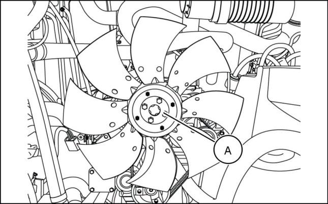
28. Place fan on hub and secure with the four retaining bolts (A)
29. Install oil cooler refer to Oil cooler - Install (A.10.A)
30. Install radiator refer to Radiator - Install (B.50.A)
931002030 24 931002028 25 931002029 26 931002027 27 84423866 25/07/2011 B.10.A / 28
31. Add engine oil.
AND PTO IN - ENGINE
ENGINE
32. Fill hydraulic oil reservoir refer to Reservoir - Filling (A.10.A)
33. Fill coolant refer to Radiator - Filling (B.50.A)
34. Lift engine hood into place on the top of the skid steer.
35. Install the left and right hand side hood mounting bolts (27)
36. Connect the hood support strut (B) to the left hand side of hood.
37. Install rear access door refer to Engine hood - Install (E.20.A)
931002026 28 931002025 29 931001682 30 84423866 25/07/2011 B.10.A / 29
38. Lower cab refer to Tilt system - Lower (E.34.A)
ENGINE - Install
SR200, SR220, SR250, SV250, SV300, TR270, TR320, TV380
DANGER
Heavy objects!
Lift and handle all heavy components using lifting equipment with adequate capacity. Always support units or parts with suitable slings or hooks. Make sure the work area is clear of all bystanders. Failure to comply will result in death or serious injury.
Prior operation: ENGINE - Remove (B.10.A)
1. Attach proper lifting straps to the eye hooks provided on the front and rear of the engine, as shown.
2. Using a suitable hoist carefully lower engine into engine compartment on the skid steer.
3. Carefully orient hydraulic pump coupler to adapter on the engine ensuring attachment of engine plate to flywheel housing.

D0076A
AND PTO IN -
ENGINE
ENGINE
931001946 1 931001944 2 931001936 3 84423866 25/07/2011 B.10.A / 30
ENGINE AND PTO IN - ENGINE
4. Install pump mounting bolts and washers (1) into pump housing.
5. Install the two rear engine mounting bolts and bushings (2)
6. Install the two front engine mounting bolts and bushings (3)
931001928 4 931001933 5 931002047 6 931001929 7 84423866 25/07/2011 B.10.A / 31
7. Verify pump mounting bolts are secure and carefully remove support brace (4)and straps (5) from pump.
ENGINE AND PTO IN - ENGINE
8. Connect the lower heater hose (6)
9. Connect the upper heater hose (7)
10. Attach heater hose support clamp (8)
931001940 8 931002114 9 931001943 10 931002050 11 84423866 25/07/2011 B.10.A / 32
11. Attach engine oil pan drain hose support clamp (9)
ENGINE AND PTO IN - ENGINE
12. Connect the wiring harness connection (10)
13. Connect the fuel pump wire connection (11)
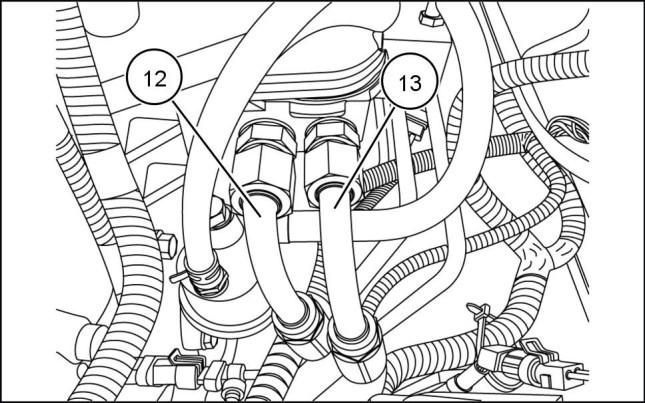
14. Connect the two remote oil filter lines (12) and (13) as previously labeled.
931001926 12 931001925 13 931001923 14 931001922 15 84423866 25/07/2011 B.10.A / 33
15. Connect throttle cable by installing the nut (A) and bolt (B) to the throttle body. Install cable support clamp and tighten the two hex head bolts (C).
16. Connect fuel supply line (14)
17. Connect fuel return line (15)
18. Connect low pressure line to the air condition compressor (16)
19. Connect wire harness connection (17) located on left hand side above motor mount.
ENGINE AND PTO IN - ENGINE
931001919 16 931001917 17 931002113 18 931001911 19 84423866 25/07/2011 B.10.A / 34
ENGINE AND PTO IN - ENGINE
20. Connect the ground to engine from battery quick disconnect (18) and cab ground (19)
21. Connect the two starter connections (D) and (E)
22. Connect the two alternator connections (F) and (G)
931001910 20 931001909 21 931001908 22 931001903 23 84423866 25/07/2011 B.10.A / 35
23. Install upper radiator hose (20) to engine and tighten hose clamp.
ENGINE AND PTO IN - ENGINE
24. Install the three mounting bolts (21) that secure air cleaner housing and bracket to frame.
25. Install the fixed hood and secure with hardware (22)
26. Connect air cleaner to turbo hose (23)
931001900 24 931001899 25 931001898 26 931001897 27 84423866 25/07/2011 B.10.A / 36
27. Connect air restriction sensors electrical connection (24)

BUY NOW Then Instant Download the Complete Manual. Thank you very much!