Link Product / Engine
Product Market Product Engine Magnum™ 180 6961 10752 CVT TIER [ZERH08100 - ] North America F4HFE613K*B002 Magnum™ 180 6961 10752 CVT TIER [ZERH08100 - ] Australia New Zealand F4HFE613K*B002 Magnum™ 200 6961 10762 CVT TIER [ZERH08100 - ] North America F4HFE613J*B005 Magnum™ 200 6961 10762 CVT TIER [ZERH08100 - ] Australia New Zealand F4HFE613J*B005 Magnum™ 220 6961 10772 CVT TIER [ZERH08100 - ] North America F4HFE613H*B003 Magnum™ 220 6961 10772 CVT TIER [ZERH08100 - ] Australia New Zealand F4HFE613H*B003 Magnum™ 240 6961 10782 CVT TIER [ZERH08100 - ] Australia New Zealand F4HFE613B*B006 Magnum™ 240 6961 10782 CVT TIER [ZERH08100 - ] North America F4HFE613B*B006 47748092 26/09/2014
Contents INTRODUCTION Engine . . . . . . . . . . . . . . . . . . . . . . . . . . . . . . . . . . . . . . . . . . . . . . . . . . . . . . . . . . . . . . . . . . . . . . . . . . . . . . . . . . . . . . . [10.001] Engine and crankcase . . . . . . . . . . . . . . . . . . . . . . . . . . . . . . . . . . . . . . . . . . . . . . . . . . . . . . . . . . . . . 10.1 [10.216] Fuel tanks . . . . . . . . . . . . . . . . . . . . . . . . . . . . . . . . . . . . . . . . . . . . . . . . . . . . . . . . . . . . . . . . . . . . . . . . . . 10.2 [10.218] Fuel injection system . . . . . . . . . . . . . . . . . . . . . . . . . . . . . . . . . . . . . . . . . . . . . . . . . . . . . . . . . . . . . . . 10.3 [10.202] Air cleaners and lines . . . . . . . . . . . . . . . . . . . . . . . . . . . . . . . . . . . . . . . . . . . . . . . . . . . . . . . . . . . . . . 10.4 [10.500] Selective Catalytic Reduction (SCR) exhaust treatment . . . . . . . . . . . . . . . . . . . . . . . . . . . 10.5 [10.400] Engine cooling system . . . . . . . . . . . . . . . . . . . . . . . . . . . . . . . . . . . . . . . . . . . . . . . . . . . . . . . . . . . . . 10.6 [10.414] Fan and drive . . . . . . . . . . . . . . . . . . . . . . . . . . . . . . . . . . . . . . . . . . . . . . . . . . . . . . . . . . . . . . . . . . . . . . 10.7 [10.310] Aftercooler . . . . . . . . . . . . . . . . . . . . . . . . . . . . . . . . . . . . . . . . . . . . . . . . . . . . . . . . . . . . . . . . . . . . . . . . . . 10.8 Engine lubrication system Power coupling . . . . . . . . . . . . . . . . . . . . . . . . . . . . . . . . . . . . . . . . . . . . . . . . . . . . . . . . . . . . . . . . . . . . . . . . . . . Drive shaft [19.1 10] Flywheel damper . . . . . . . . . . . . . . . . . . . . . . . . . . . . . . . . . . . . . . . . . . . . . . . . . . . . . . . . . . . . . . . . . . . 19.2 T ransmission . . . . . . . . . . . . . . . . . . . . . . . . . . . . . . . . . . . . . . . . . . . . . . . . . . . . . . . . . . . . . . . . . . . . . . . . . . . . . . [21.200] Dropbox . . . . . . . . . . . . . . . . . . . . . . . . . . . . . . . . . . . . . . . . . . . . . . . . . . . . . . . . . . . . . . . . . . . . . . . . . . . . 21.1 [21.504] Continuously V ariable T ransmission (CVT) . . . . . . . . . . . . . . . . . . . . . . . . . . . . . . . . . . . . . . . . 21.2 [21.505] Continuously
ransmission (CVT) external controls . . . . . . . . . . . . . . . . . . . . . . 21.3 [21.506] Continuously
ransmission
lubrication system . . . . . . . . . . . . . . . . . . . . 21.4
ransmission
[23.314] Drive shaft . . . . . . . . . . . . . . . . . . . . . . . . . . . . . . . . . . . . . . . . . . . . . . . . . . . . . . . . . . . . . . . . . . . . . . . . . . 23.2 Front axle system . . . . . . . . . . . . . . . . . . . . . . . . . . . . . . . . . . . . . . . . . . . . . . . . . . . . . . . . . . . . . . . . . . . . . . .
47748092 26/09/2014
V ariable T
V ariable T
(CVT)
Continuously V ariable T
(CVT) internal components Drive (4WD) system control
Powered front axle Front bevel gear set and dif ferential
Final drive steering and shafts Axle suspension control
bevel gear set and dif ferential
T ake-Of f (PT
T rear Power T f (PT Brakes and controls
Hydraulic service brakes
[27.100]
. . . . . . . . . . . . . . . . . . . . . . . . . . . . . . . . . . . . . . . . . . . . . . . . . . . . . . . . . . . . . . . . . . 27.1 [27.106] Rear
. . . . . . . . . . . . . . . . . . . . . . . . . . . . . . . . . . . . . . . . . . . . . . . . 27.2 Power
. . . . . . . . . . . . . . . . . . . . . . . . . . . . . . . . . . . . . . . . . . . . . . . . . . . . . . . . . . . . . . . . . [31.104]
. . . . . . . . . . . . . . . . . . . . . . . . . . . . . . . . . . . . . . . . . . . . . . . . . . . . . . 31.1
[33.202]
. . . . . . . . . . . . . . . . . . . . . . . . . . . . . . . . . . . . . . . . . . . . . . . . . . . . . . . . . . . 33.1 [33.1 10] Parking brake parking lock . . . . . . . . . . . . . . . . . . . . . . . . . . . . . . . . . . . . . . . . . . . . . . . . . . . . . . 33.2 [33.220] T railer brake hydraulic control . . . . . . . . . . . . . . . . . . . . . . . . . . . . . . . . . . . . . . . . . . . . . . . . . . . . . . 33.3 Hydraulic systems . . . . . . . . . . . . . . . . . . . . . . . . . . . . . . . . . . . . . . . . . . . . . . . . . . . . . . . . . . . . . . . . . . . . . . . Hydraulic systems Pump control valves Charge pump V ariable displacement pump 14] hitch control valve 16] hitch cylinder Remote control valves Reservoir , cooler , and filters Hitches, drawbars, and implement couplings . . . . . . . . . . . . . . . . . . . . . . . . . . . . . . . . . . 10] Rear hitch Frames and ballasting . . . . . . . . . . . . . . . . . . . . . . . . . . . . . . . . . . . . . . . . . . . . . . . . . . . . . . . . . . . . . . . . . [39.140] Ballasts and supports . . . . . . . . . . . . . . . . . . . . . . . . . . . . . . . . . . . . . . . . . . . . . . . . . . . . . . . . . . . . . . 39.1 Steering . . . . . . . . . . . . . . . . . . . . . . . . . . . . . . . . . . . . . . . . . . . . . . . . . . . . . . . . . . . . . . . . . . . . . . . . . . . . . . . . . . . . . Steering control Hydraulic control components 47748092 26/09/2014
Rear axle system
Powered rear axle
Rear control
14]
Pump Wheels . . . . . . . . . . . . . . . . . . . . . . . . . . . . . . . . . . . . . . . . . . . . . . . . . . . . . . . . . . . . . . . . . . . . . . . . . . . . . . . . . . . . . . [44.520] Rear wheels . . . . . . . . . . . . . . . . . . . . . . . . . . . . . . . . . . . . . . . . . . . . . . . . . . . . . . . . . . . . . . . . . . . . . . . . 44.1 Cab climate control . . . . . . . . . . . . . . . . . . . . . . . . . . . . . . . . . . . . . . . . . . . . . . . . . . . . . . . . . . . . . . . . . . . . . Heating Air conditioning Cab pressurizing system Electrical systems . . . . . . . . . . . . . . . . . . . . . . . . . . . . . . . . . . . . . . . . . . . . . . . . . . . . . . . . . . . . . . . . . . . . . . . [55.010] Fuel injection system . . . . . . . . . . . . . . . . . . . . . . . . . . . . . . . . . . . . . . . . . . . . . . . . . . . . . . . . . . . . . . . 55.1 [55.01 Fuel tank system . . . . . . . . . . . . . . . . . . . . . . . . . . . . . . . . . . . . . . . . . . . . . . . . . . . . . . . . . . . . . . . . . . . 55.2 [55.014] Engine intake and exhaust system . . . . . . . . . . . . . . . . . . . . . . . . . . . . . . . . . . . . . . . . . . . . . . . . . 55.3 [55.024] T ransmission control system . . . . . . . . . . . . . . . . . . . . . . . . . . . . . . . . . . . . . . . . . . . . . . . . . . . . . . . 55.4 [55.031] Parking brake electrical system . . . . . . . . . . . . . . . . . . . . . . . . . . . . . . . . . . . . . . . . . . . . . . . . . . . . 55.5 [55.045] Front axle control system . . . . . . . . . . . . . . . . . . . . . . . . . . . . . . . . . . . . . . . . . . . . . . . . . . . . . . . . . . 55.6 [55.046] Rear axle control system . . . . . . . . . . . . . . . . . . . . . . . . . . . . . . . . . . . . . . . . . . . . . . . . . . . . . . . . . . . 55.7 Steering control system V and (HV AC) control system Cab V and (HV AC) controls Harnesses and connectors 1 Rear hitch electronic control system Engine starting system Alternator Battery W arning and instruments Cab controls Wiper and washer system Electronic modules Selective Catalytic Reduction (SCR) electrical system 47748092 26/09/2014
F AUL T CODES cab, and decals Engine hood and panels [90.102] Engine shields, hood latches, and trims . . . . . . . . . . . . . . . . . . . . . . . . . . . . . . . . . . . . . . . . . . . 90.2 [90.124] operator seat . . . . . . . . . . . . . . . . . . . . . . . . . . . . . . . . . . . . . . . . . . . . . . 90.3 [90.150] Cab . . . . . . . . . . . . . . . . . . . . . . . . . . . . . . . . . . . . . . . . . . . . . . . . . . . . . . . . . . . . . . . . . . . . . . . . . . . . . . . . . 90.4 [90.151] Cab interior . . . . . . . . . . . . . . . . . . . . . . . . . . . . . . . . . . . . . . . . . . . . . . . . . . . . . . . . . . . . . . . . . . . . . . . . . 90.5 47748092 26/09/2014

INTRODUCTION 47748092 26/09/2014 1
Contents INTRODUCTION Foreword - Important notice regarding equipment servicing . . . . . . . . . . . . . . . . . . . . . . . . . . . . . . . . . . . . 3 Safety rules . . . . . . . . . . . . . . . . . . . . . . . . . . . . . . . . . . . . . . . . . . . . . . . . . . . . . . . . . . . . . . . . . . . . . . . . . . . . . . . . . . . . . 4 T orque - Minimum tightening torques for normal assembly . . . . . . . . . . . . . . . . . . . . . . . . . . . . . . . . . . . . . 5 Capacities . . . . . . . . . . . . . . . . . . . . . . . . . . . . . . . . . . . . . . . . . . . . . . . . . . . . . . . . . . . . . . . . . . . . . . . . . . . . . . . . . . . . . Product identification . . . . . . . . . . . . . . . . . . . . . . . . . . . . . . . . . . . . . . . . . . . . . . . . . . . . . . . . . . . . . . . . . . . . . . . . . . 1 1 47748092 26/09/2014 2
Foreword - Important notice regarding equipment servicing
All repair and maintenance work listed this manual must carried out only qualified dealership strictly complying with the instructions and whenever the special
Anyone who performs repair and maintenance operations without complying with the procedures provided herein shall responsible for any subsequent
The manufacturer and all the organizations its distribution chain, including - without limitationnational, regional, local reject any responsibility for damages caused parts and / components not approved the facturer , including those used for the servicing repair the product manufactured marketed the manufacturer any case, warranty given attributed the product manufactured marketed the manufacturer case damages caused parts and / components not approved the manufacturer
The information this manual - - date the date the the policy the manufacturer for continuous Some information could not updated due modifications a technical commercial type, changes the laws and regulations dif ferent countries.
case refer your CASE Sales and Service
INTRODUCTION
26/09/2014 3
47748092
Safety rules
Personal safety
This the safety alert used alert you potential personal injury Obey all safety messages that follow this symbol avoid possible death injury

Throughout this manual and machine you will find the signal words W and CAUTION followed special These precautions are intended for the personal safety you and those working with
Read and understand all the safety messages this manual before you operate service the
DANGER indicates a hazardous situation not will result death serious injury The color associated with DANGER
W ARNING indicates a hazardous situation not could result death serious injury
The color associated with W ARNING
used with the safety alert indicates a hazardous situation not could result minor moderate injury The color associated with CAUTION YELLOW
F AILURE T O FOLLOW DANGER, W ARNING, AND CAUTION MESSAGES COULD RESUL T DEA SERIOUS INJUR Y .
Machine safety
NOTICE: Notice indicates a situation which, not avoided, could result machine property damage. The color associated with Notice
Throughout this manual you will find the signal word Notice followed special instructions prevent machine property The word Notice used address practices not related personal safety Information
NOTE: Note indicates additional information which clarifies steps, procedures, other information this manual.
Throughout this manual you will find the word Note followed additional information about a other information the The word Note not intended address personal safety property
INTRODUCTION
47748092 26/09/2014 4
T orque - Minimum tightening torques for normal assembly
METRIC
INTRODUCTION
NON - FLANGED HARDW ARE NOM. SIZE CLASS 8.8 BOL T and CLASS 8 NUT CLASS 10.9 BOL T and CLASS NUT LOCKNUT CL.8 W / CL8.8 BOL T LOCKNUT CL.10 W / CL10.9 BOL T UNPLA TED PLA TED W / ZnCr UNPLA TED PLA TED W / ZnCr N·m ( ) N·m ( ) N·m ( ) N·m ( ) 2 N·m ( ) N·m ( ) N·m ( ) N·m ( ) N·m ( ) N·m ( ) 4 N·m ( ) N·m ( ) N·m ( ) N·m ( ) 1 1 N·m ( ) N·m ( 128 ) N·m ( ) N·m ( ) N·m ( 163 ) N·m ( 217 ) N·m ( 234 ) N·m ( 1 ) N·m ( 151 ) N·m ( 212 ) M10 ( ) N·m ( ) ( ) N·m ( ) N·m ( ) N·m ( ) M12 ( ) N·m ( ) ( ) 121 N·m ( ) N·m ( ) N·m ( ) M16 158 ( 1 ) 210 ( 155 ) 225 ( 166 ) 301 ( 222 ) 143 ( 106 ) 205 ( 151 ) M20 319 ( 235 ) 425 ( 313 ) 440 ( 325 ) 587 ( 433 ) 290 ( 214 ) 400 ( 295 ) M24 551 ( 410 ) 735 N·m ( 500 ) 762 ( 560 ) 1016 N·m ( 750 ) 501 ( 370 ) 693 ( 510 )
through hardware torque specifications are shown poundinches. M10 through M24 hardware torque specifications are shown pound47748092 26/09/2014 5
NOTE:
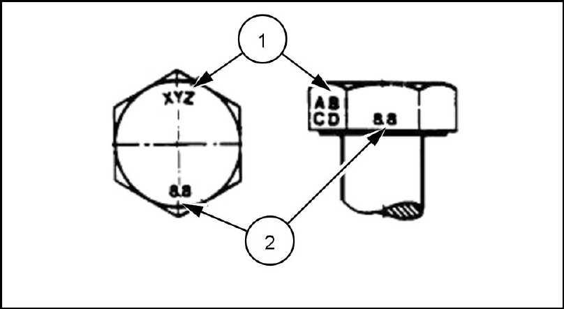
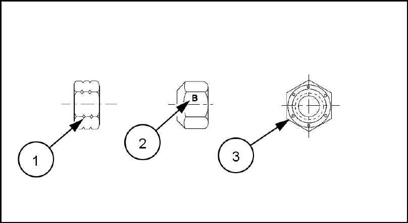
INTRODUCTION METRIC FLANGED HARDW ARE NOM. SIZE CLASS 8.8 BOL T and CLASS 8 NUT CLASS 10.9 BOL T and CLASS NUT LOCKNUT CL.8 W / CL8.8 BOL T LOCKNUT CL.10 W / CL10.9 BOL T UNPLA TED PLA TED W / ZnCr UNPLA TED PLA TED W / ZnCr 2.4 N·m ( ) 3.2 N·m ( ) 3.5 N·m ( ) 4.6 N·m ( ) 2.2 N·m ( ) 3.1 N·m ( ) 4.9 N·m ( ) 6.5 N·m ( ) 7.0 N·m ( ) 9.4 N·m ( ) 4.4 N·m ( ) 6.4 N·m ( ) 8.3 ( ) 1 1 ( ) ( 105 ) ( 141 ) 7.5 ( ) 1 1 ( ) ( 179 ) ( 240 ) ( 257 ) ( 343 ) ( 163 ) ( 240 ) M10 N·m ( ) N·m ( ) N·m ( ) N·m ( ) N·m ( ) N·m ( ) M12 N·m ( ) N·m ( ) 100 N·m ( ) 134 N·m ( ) N·m ( ) N·m ( ) M16 174 N·m ( 128 ) 231 N·m ( 171 ) 248 N·m ( 183 ) 331 N·m ( 244 ) 158 N·m ( 1 ) 226 N·m ( 167 ) M20 350 N·m ( 259 ) 467 N·m ( 345 ) 484 N·m ( 357 ) 645 N·m ( 476 ) 318 N·m ( 235 ) 440 N·m ( 325 ) M24 607 N·m ( 447 ) 809 N·m ( 597 ) 838 N·m ( 618 ) 1 1 N·m ( 824 ) 552 N·m ( 407 ) IDENTIFICA TION Metric Hex head and carriage bolts, classes 5.6 and 20083680 1 Identification Property Class Metric Hex nuts and locknuts, classes and 20083681 2 47748092 26/09/2014 6
INTRODUCTION Identification Property Class Clock Marking Property Class and Identification marks ° apart indicate Class and marks 120 ° apart indicate Class INCH NON - FLANGED HARDW ARE NOMINAL SIZE SAE GRADE 5 BOL T and NUT SAE GRADE 8 BOL T and NUT LOCKNUT GrB W / Gr5 BOL T LOCKNUT GrC W / Gr8 BOL T UNPLA TED PLA TED SIL VER PLA TED W / ZnCr GOLD UNPLA TED PLA TED SIL VER PLA TED W / ZnCr GOLD 1 / 4 8 N·m ( ) 1 1 N·m ( ) ( 106 ) ( 142 ) 8.5 ( ) 12.2 N·m ( 109 ) 5 / ( 150 ) ( 204 ) ( 212 ) ( 283 ) 17.5 ( 155 ) ( 220 ) 3 / 8 ( ) ( ) ( ) ( ) N·m ( ) N·m ( ) 7 / N·m ( ) N·m ( ) N·m ( ) N·m ( ) N·m ( ) N·m ( ) 1 / 2 N·m ( ) N·m ( ) 104 N·m ( ) 139 N·m ( 103 ) N·m ( ) 108 N·m ( ) 9 / 107 N·m ( ) 142 N·m ( 105 ) 150 N·m ( 1 1 1 ) 201 N·m ( 148 ) 1 1 1 N·m ( ) 156 N·m ( 1 ) 5 / 8 147 N·m ( 108 ) 196 N·m ( 145 ) 208 N·m ( 153 ) 277 N·m ( 204 ) 153 N·m ( 1 ) 215 N·m ( 159 ) 3 / 4 261 N·m ( 193 ) 348 N·m ( 257 ) 369 N·m ( 272 ) 491 N·m ( 362 ) 271 N·m ( 200 ) 383 N·m ( 282 ) 7 / 8 420 ( 310 ) 561 ( 413 ) 594 ( 438 ) 791 ( 584 ) 437 N·m ( 323 ) 617 N·m ( 455 ) 1 630 ( 465 ) 841 ( 620 ) 890 ( 656 ) 1 187 ( 875 ) 654 ( 483 ) 924 ( 681 ) NOTE: For Imperial 1 / 4 and 5 / hardware torque specifications are shown pound - 3 / 8 through 1 hardware torque specifications are shown pound47748092 26/09/2014 7
IDENTIFICA TION
INCH FLANGED HARDW ARE NOMINAL SIZE SAE GRADE 5 BOL T and NUT SAE GRADE 8 BOL T and NUT LOCKNUT GrF W / Gr5 BOL T LOCKNUT GrG W / Gr8 BOL T UNPLA TED PLA TED SIL VER PLA TED W / ZnCr GOLD UNPLA TED PLA TED SIL VER PLA TED W / ZnCr GOLD 1 / 4 9 ( ) N·m ( 106 ) N·m ( 1 ) N·m ( 150 ) 8 ( ) N·m ( 106 ) 5 / N·m ( 168 ) N·m ( 221 ) N·m ( 230 ) N·m ( 310 ) N·m ( 150 ) N·m ( 212 ) 3 / 8 ( ) ( ) ( ) ( ) ( ) ( ) 7 / ( ) ( ) ( ) 100 ( ) N·m ( ) N·m ( ) 1 / 2 N·m ( ) 108 N·m ( ) 1 N·m ( ) 153 N·m ( 1 ) N·m ( ) 104 N·m ( ) 9 / 1 N·m ( ) 156 N·m ( 1 ) 165 N·m ( 122 ) 221 N·m ( 163 ) 106 N·m ( ) 157 N·m ( 1 ) 5 / 8 162 N·m ( 1 ) 216 N·m ( 159 ) 228 N·m ( 168 ) 304 N·m ( 225 ) 147 N·m ( 108 ) 207 N·m ( 153 ) 3 / 4 287 N·m ( 212 ) 383 N·m ( 282 ) 405 N·m ( 299 ) 541 N·m ( 399 ) 261 N·m ( 193 ) 369 N·m ( 272 ) 7 / 8 462 N·m ( 341 ) 617 N·m ( 455 ) 653 N·m ( 482 ) 871 N·m ( 642 ) 421 N·m ( 1 ) 594 N·m ( 438 ) 1 693 N·m ( 512 ) 925 ( 682 ) 979 ( 722 ) 1305 ( 963 ) 631 N·m ( 465 ) 890 N·m ( 656 )
INTRODUCTION
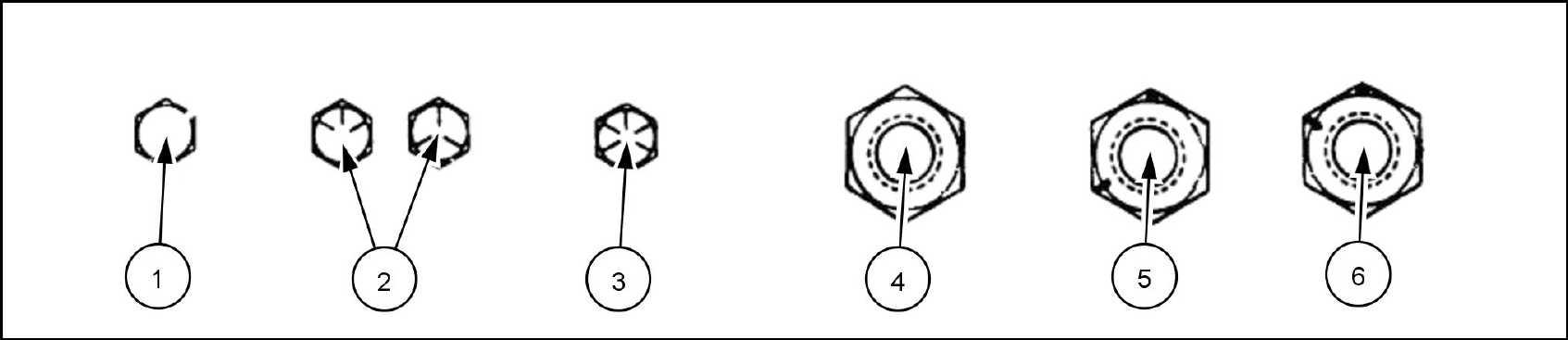
Inch Bolts and free - spinning nuts 20083682 3 Grade Marking Examples SAE Grade Identification 1 Grade 2 - Marks 4 Grade 2 Nut - Marks 2 Grade 5 - Three Marks 5 Grade 5 Nut - Marks 120 ° Apart 3 Grade 8 - Five Marks 6 Grade 8 Nut - Marks ° Apart 47748092 26/09/2014 8
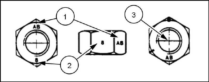
Inch Lock Nuts, All Metal (Three optional methods)
INTRODUCTION
20090268 4 Grade Identification Grade Corner Marking Method (1) Flats Marking Method (2) Clock Marking Method (3) Grade A Notches Mark Marks Grade B One Circumferential Notch Letter B Three Marks Grade C T Circumferential Notches Letter C Six Marks 47748092 26/09/2014 9
Capacities
INTRODUCTION
Magnum 180, 200, 220 and 240 System Metric U.S. Imperial Engine Oil CASE AKCELA UNITEK NO. SBL - 4 CASE AKCELA NO. ENGINE OIL filter change l gal gal With filter change l 4.36 gal gal Cooling system 23.65 l 6.25 gal 5.2 gal T ransmission / hydraulic system CASE AKCELA - TRAN® TRACTION Full Powershift l gal gal Continuous V ariable T ransmission (CVT) 100 l 26.4 gal gal Mechanical Front Drive (MFD) T UTELA H YPOIDE GEAR LUBE CASE AKCELA GEAR 135 H 85W - 140 Case fixed front axle Dif ferential 1 1 l 1 Planetary (each) l Case saddle suspended front axle Dif ferential 17.5 l 18.5 30.8 Planetary (each) 4.3 l 4.5 7.5 Mechanical Front Drive (MFD) gearbox T UTELA H YPOIDE G EAR LUBE SAE 85W - 140 275 9.3 9.7 Fuel tank 586.7 l 155 gal 129 gal DEF / AdBlue® tank l gal gal 47748092 26/09/2014
INTRODUCTION
Product identification
T ractor model and Product Identification Number (PIN)
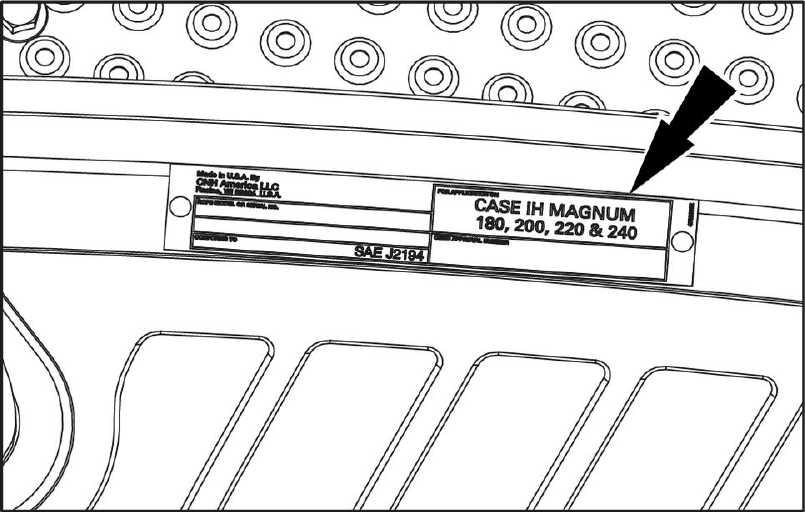
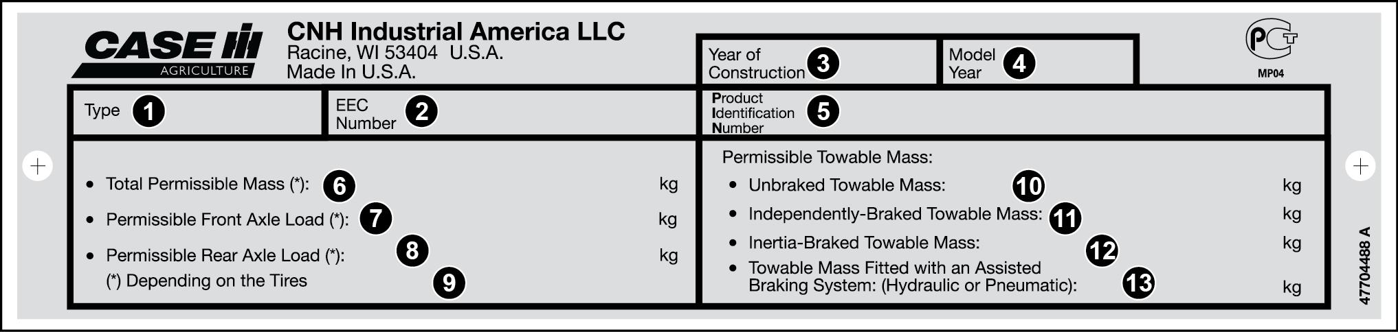
W rite your model number , Product Identification Number (PIN) serial number major components the lines give these numbers your dealer when you need parts information for your
RAIL14TR02078EA 1
T ype
Permissible rear axle load
EEC number (*) Depending the tires
Y ear construction
Model year
Product identification number
T otal permissible mass
Permissible front axle load
Model : PIN
NOTE: Located right hand front frame
Permissible towable mass:
• Unbraked towable mass:
• 1
Independently - braked towable mass:
• Inertia braked towable mass:
• T owable mass fitted with assisted braking system: (hydraulic pneumatic)
RCPH08CCH625AAB 2
Roll Over Protective Structure (ROPS) serial number
NOTE: Located the right hand cab floor
RAIL13TR04461AA 3
47748092 26/09/2014 1 1
INTRODUCTION
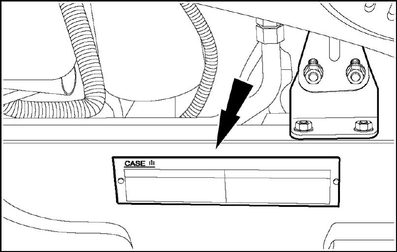
Engine serial number
NOTE: Located the right hand side the engine the A serial number decal also located the top the valve cover
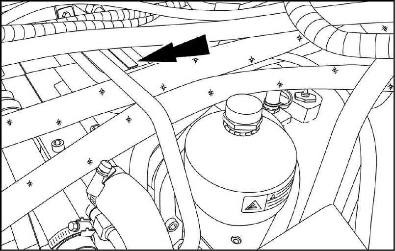
T
ransmission serial number
NOTE: Located the right hand side the Powershift transmission behind and the left the battery carrier Located the top the Continuously V ariable T sion (CVT) parallel the accumulator
Axle serial number
Class fixed front axle: Located the front right hand side the axle housing
Class saddle suspended front axle: Located the rear left hand side the axle housing (not
RCPH10CCH010BAA 6
RCPH10CCH009BAA 4
RAIL13TR03691AA 5
47748092 26/09/2014
INTRODUCTION
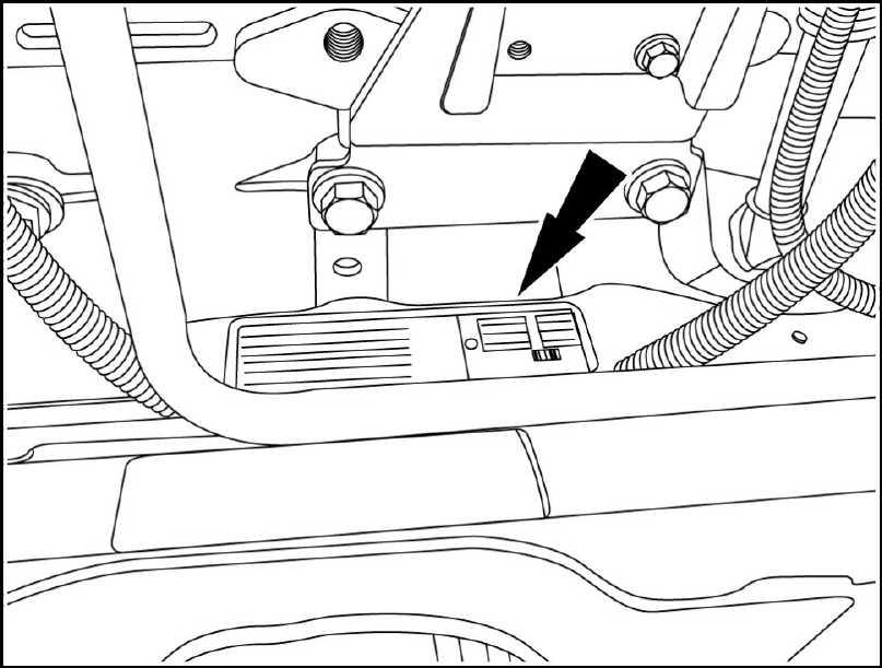
Driveline serial number
Located the right hand side the drop box below the exhaust elbow RAIL13TR03700AA 7 47748092
26/09/2014
INTRODUCTION 47748092 26/09/2014
SERVICEMANUAL Engine 4774809226/09/2014
Contents Engine[10.001] Engine and crankcase . . . . . . . . . . . . . . . . . . . . . . . . . . . . . . . . . . . . . . . . . . . . . . . . . . . . . . . . . . . . . . . 10.1 Fuel tanks Fuel injection system [10.202] Air cleaners and lines . . . . . . . . . . . . . . . . . . . . . . . . . . . . . . . . . . . . . . . . . . . . . . . . . . . . . . . . . . . . . . . . 10.4 Selective Catalytic Reduction (SCR) exhaust treatment Engine cooling system [10.414] Fan and drive . . . . . . . . . . . . . . . . . . . . . . . . . . . . . . . . . . . . . . . . . . . . . . . . . . . . . . . . . . . . . . . . . . . . . . . . 10.7 [10.310] Aftercooler . . . . . . . . . . . . . . . . . . . . . . . . . . . . . . . . . . . . . . . . . . . . . . . . . . . . . . . . . . . . . . . . . . . . . . . . . . . . 10.8 Engine lubrication system 47748092 26/09/2014
EngineEngine and crankcase - 001 Magnum™ 180 6961 10752 CVT TIER [ZERH08100 - ] Magnum™ 200 6961 10762 CVT TIER [ZERH08100 - ] Magnum™ 220 6961 10772 CVT TIER [ZERH08100 - ] Magnum™ 240 6961 10782 CVT TIER [ZERH08100 - ] 47748092 26/09/2014 10.1 [10.001] / 1
Contents EngineEngine and crankcase - 001 SER VICE Engine Remove 3 Install 47748092 26/09/2014 10.1 [10.001] / 2
Engine - Engine and crankcase
Engine - Remove
Prior operation:
Battery - Disconnect (55.302)
Prior operation:
Air intake lines Air scoop - Remove (10.202)
Prior operation:
Engine cooling system - Remove (10.400)
Prior operation:
Air conditioning - Recover - Refrigerant
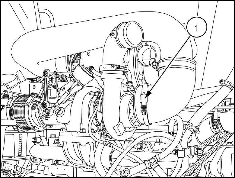
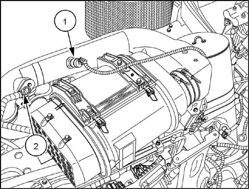
Disconnect the air sensor connector (1) and the crankcase vent hose (2) from the air cleaner outlet tube.
Disengage the clamp and remove the air cleaner outlet hose (1) from the turbocharger
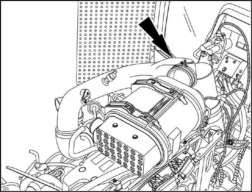
Disengage the clamp the air cleaner and remove the air outlet
RAIL13TR01577AA 1
RAIL13TR01582AA 2
RAIL13TR01583AA 3
47748092 26/09/2014
/ 3
10.1 [10.001]
Remove the air cleaner mounting bolts (1) from each side the air cleaner bracket (left side
RAIL13TR01585AA 4
Remove the air cleaner along with the mounting
RAIL13TR01587AA 5
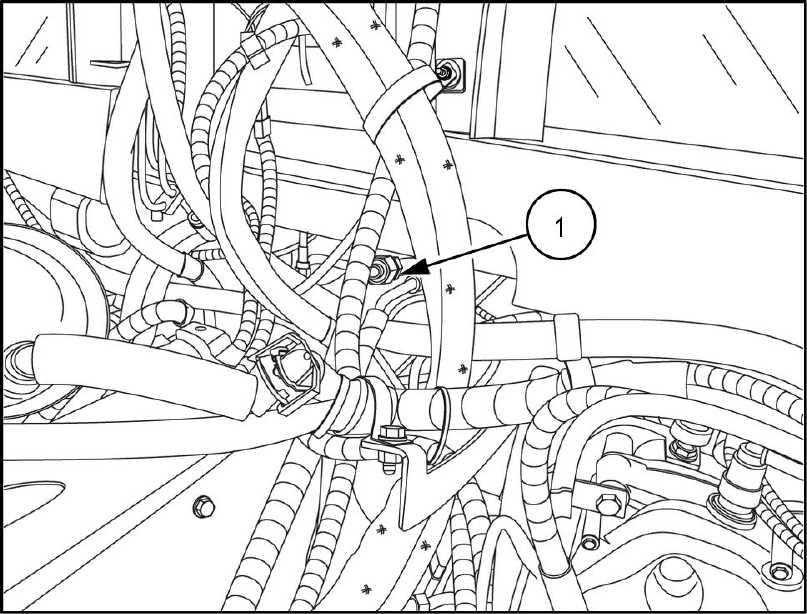
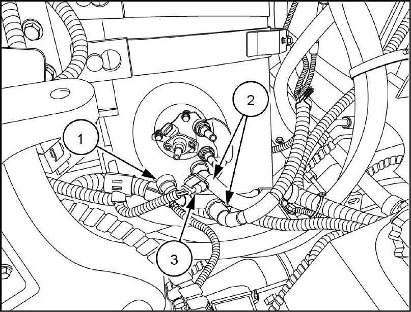
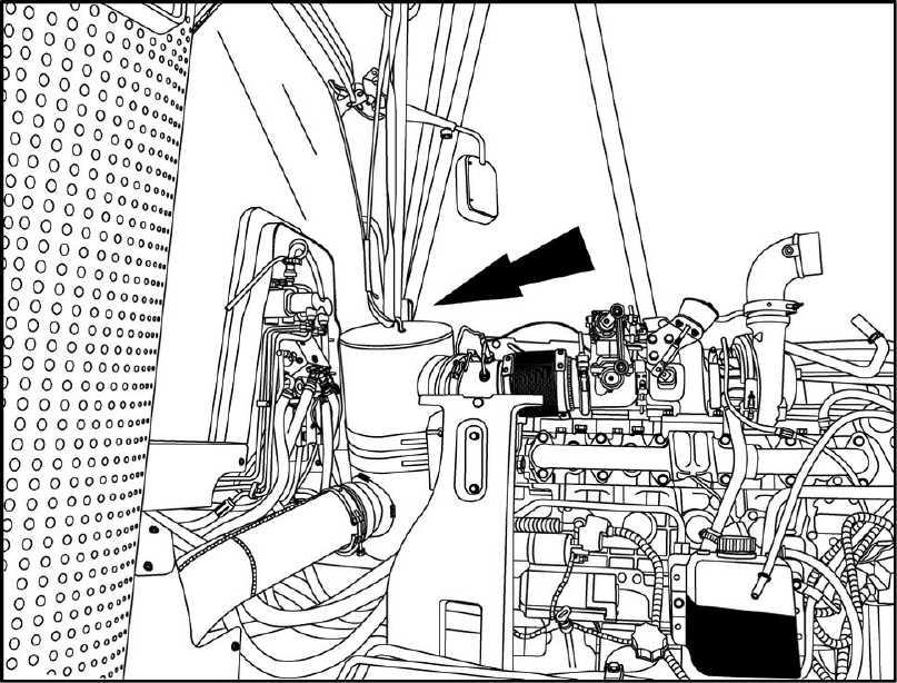
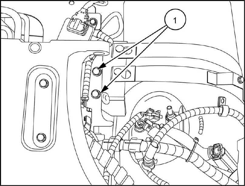
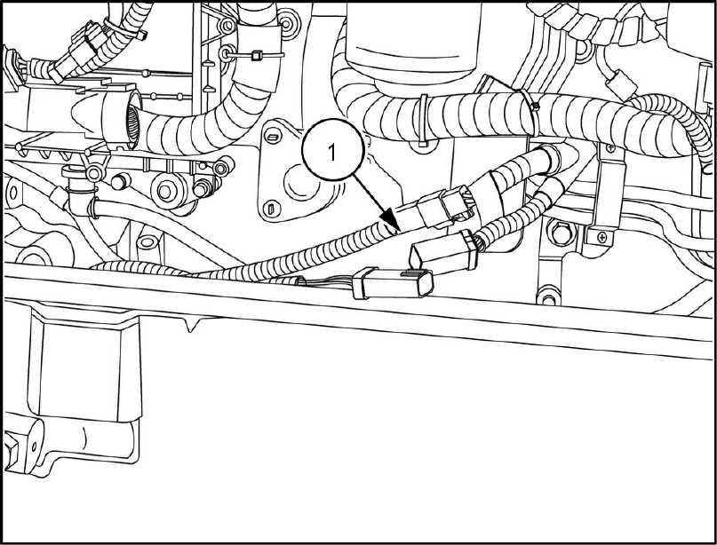
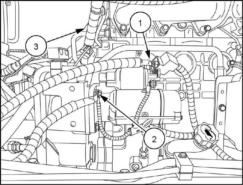
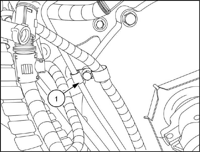
Disconnect the Diesel Exhaust Fluid (DEF) / AdBlue® line (1) , the coolant supply and return lines (2) and the electrical connector (3) from the dosing Squeeze the tabs together and lift the hose straight f the fitting.
Engine - Engine and crankcase
6 47748092 26/09/2014 10.1 [10.001] / 4
RAIL13TR01586AA
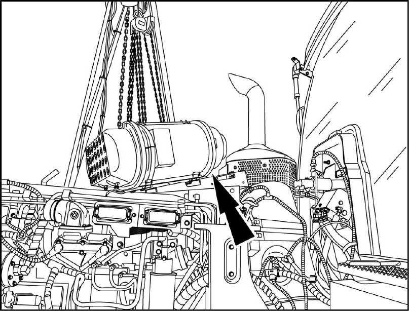
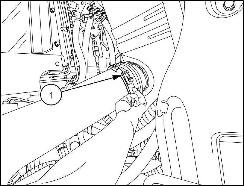
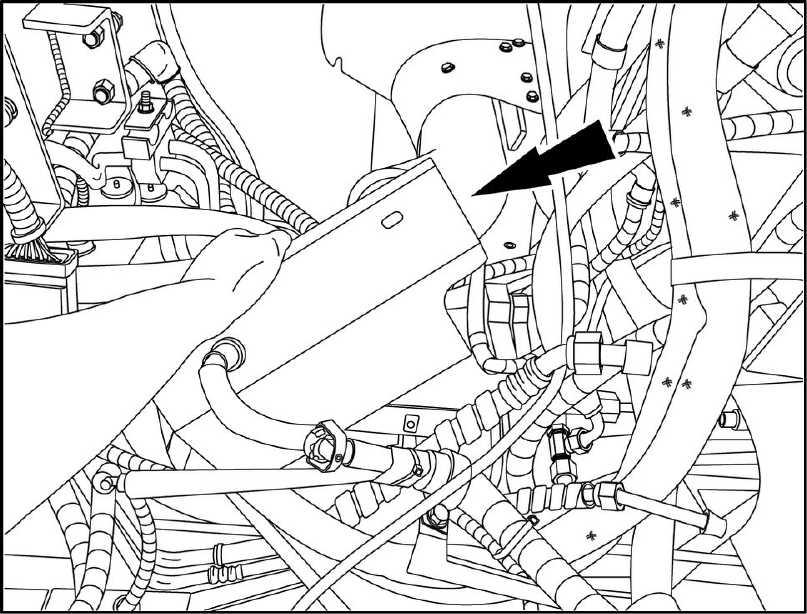
Disengage the clamp (1) from the input side the Diesel Exhaust Catalyst RAIL13TR01589AA
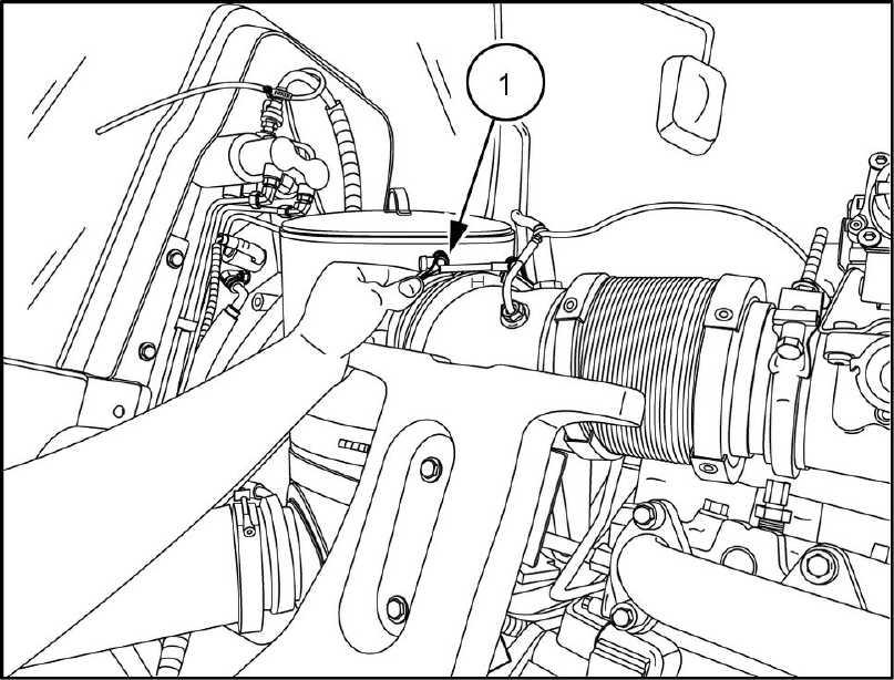
Disengage the clamp (1) from the output side the RAIL13TR01590AA
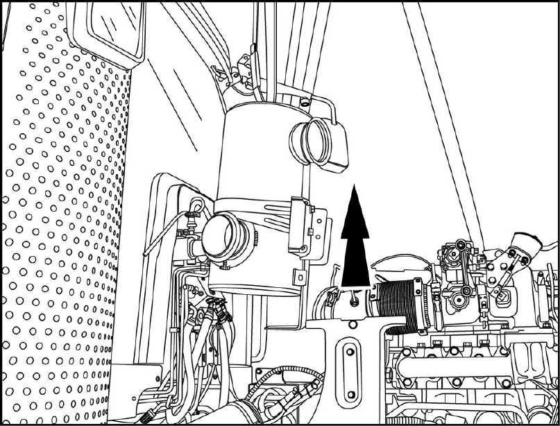
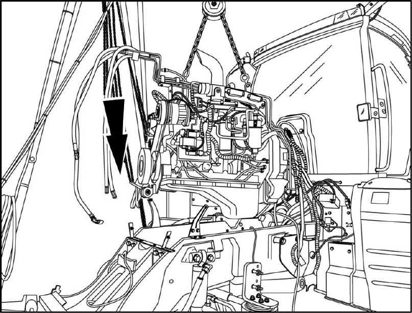
Using proper lifting secure a strap the lifting bracket the RAIL13TR01592AA
Engine - Engine and crankcase
7
8
47748092 26/09/2014 10.1 [10.001] / 5
9
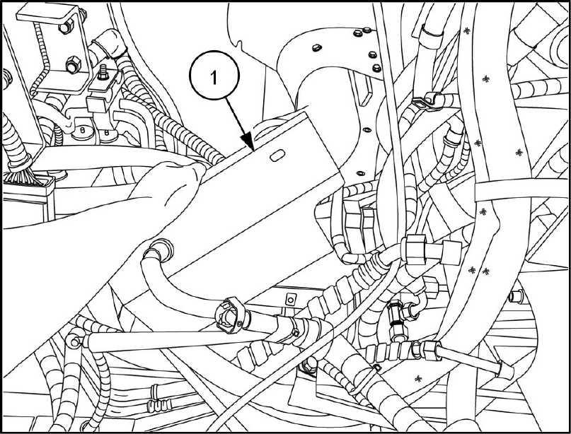
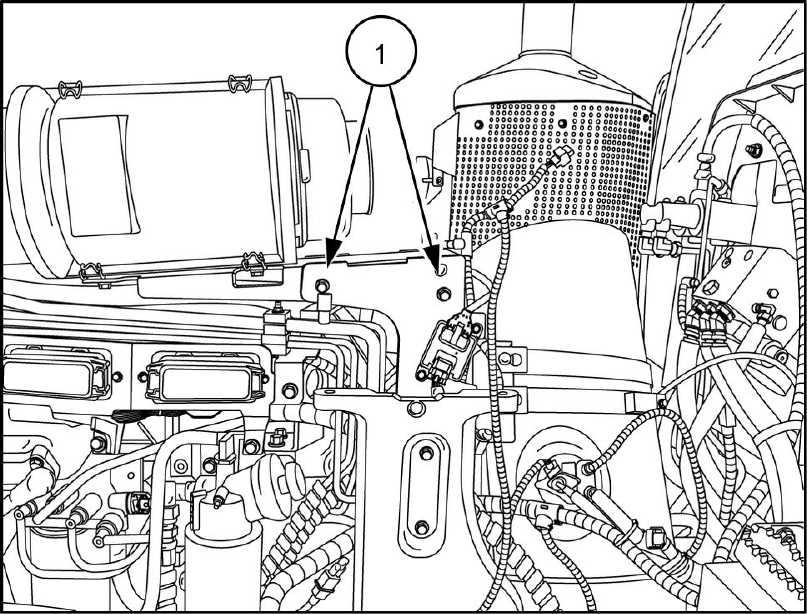
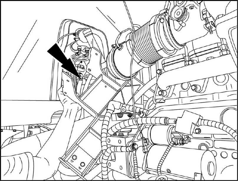
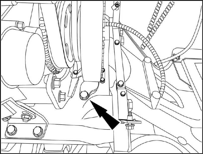
10. With tension the lifting strap, remove the mounting bracket bolts (1) for the DOC from both sides the bracket (left hand side
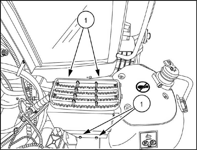
Raise the DOC and remove from the tractor
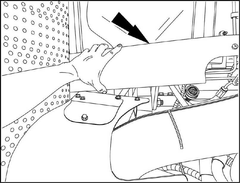
Remove the four mounting bolts (1) for the window Remove the
Engine - Engine and crankcase
RAIL13TR01593AA
1
1 1
RAIL13TR01596AA
47748092 26/09/2014 10.1 [10.001] / 6
RAIL13TR01594AA
13. Cut the tie straps the DEF / AdBlue® system
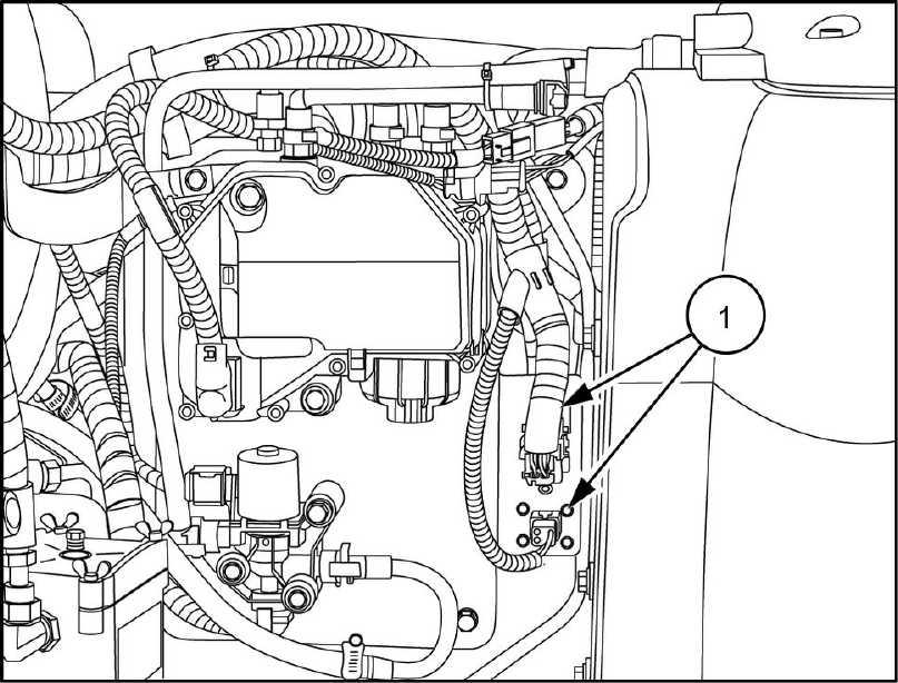
Disconnect the two harness connectors (1)
RAIL13TR01597AA
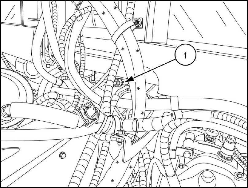
Disconnect the V auxiliary connector (1) and the inlet fuel line from the fuel separator (2)
RAIL13TR01603AA
Disconnect the two connectors (1) for the front axle
RAIL13TR01625AA
Engine - Engine and crankcase
47748092 26/09/2014 10.1 [10.001] / 7
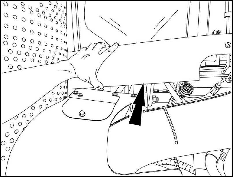
16. Remove the cab trim panels from both sides the (right hand side
Disconnect and cap the high and low pressure air ditioning lines (1) located under the front the
Remove the cover plate from the driveshaft (left hand side
Engine - Engine and crankcase
RAIL13TR0161 1AA
RAIL13TR01599AA
47748092 26/09/2014 10.1 [10.001] / 8
RAIL13TR01600AA
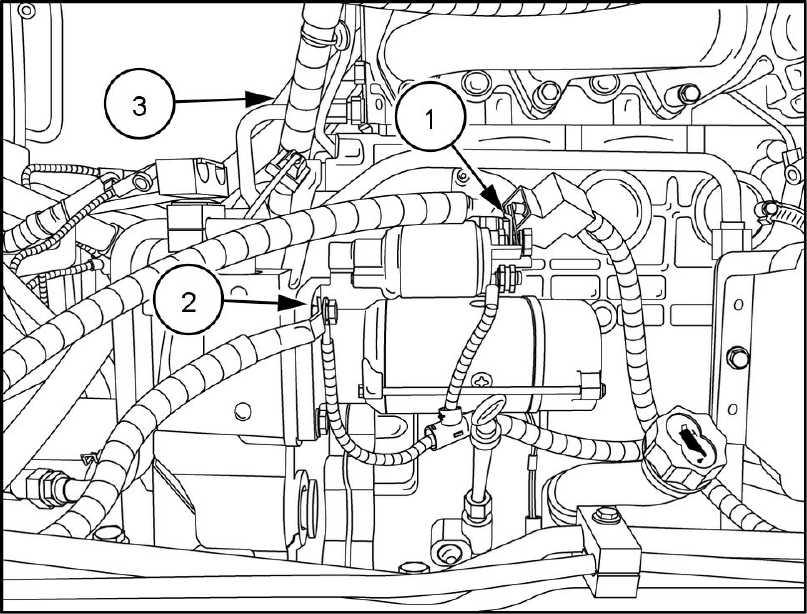
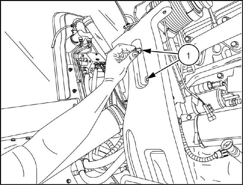
19. Remove the bolts (1) for the mounting bracket for the driveshaft cover Disconnect the driveshaft from the RAIL13TR01602AA
Remove the bolts (1) for the mounting bracket for the air cleaner / DOC from the hood support
Remove the mounting bolts (left hand side shown) which secure the hood support bracket front frame and remove the bracket. Repeat for right hand side. RAIL13TR01608AA
Remove the air cleaner / DOC RAIL13TR01609AA
Engine - Engine and crankcase
47748092 26/09/2014 10.1 [10.001] / 9
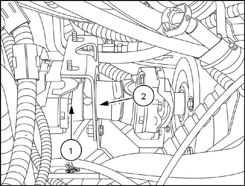
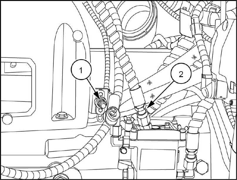
23. Disconnect the starter positive (1) and ground (2)
Disconnect the chassis engine harness connector (3) .
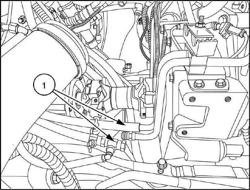
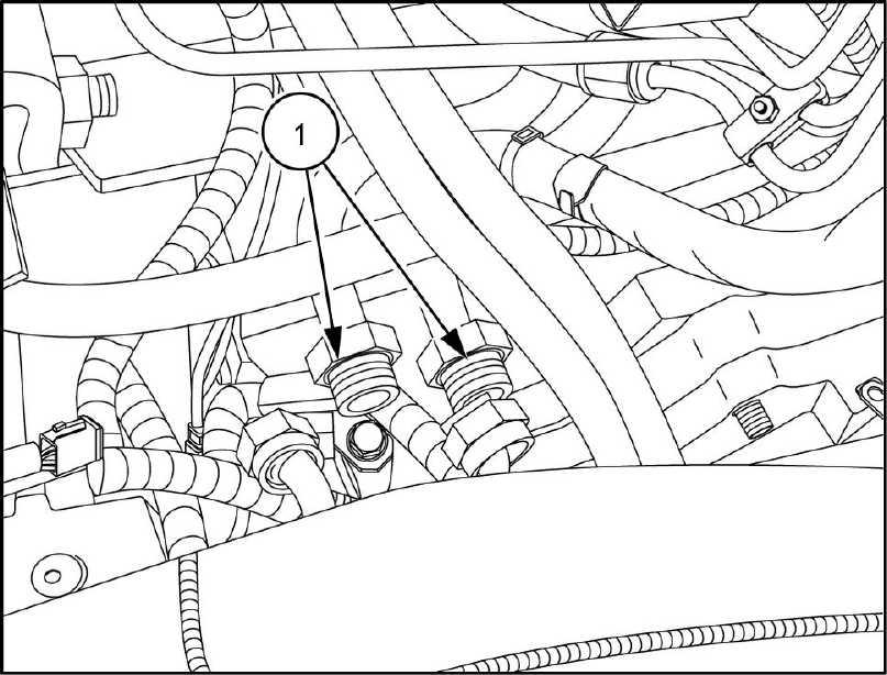
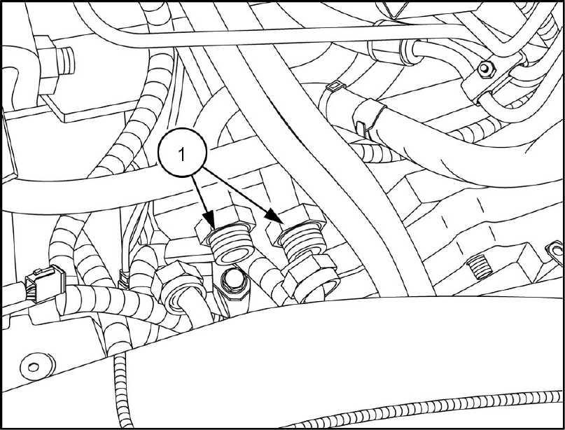
Disconnect the two hydraulic oil cooler lines (1) Cap plug all fittings and
Disconnect the two coolant hoses (1)
Engine
Engine -
and crankcase
RAIL13TR01613AA
RAIL13TR01615AA
47748092 26/09/2014 10.1 [10.001] /
RAIL13TR01616AA
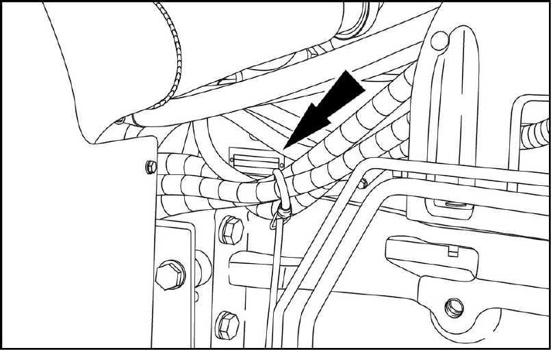
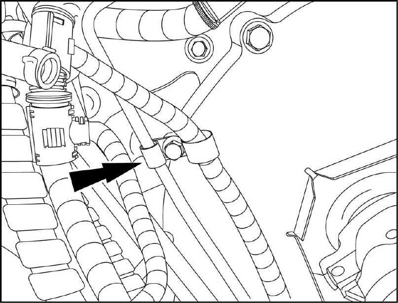
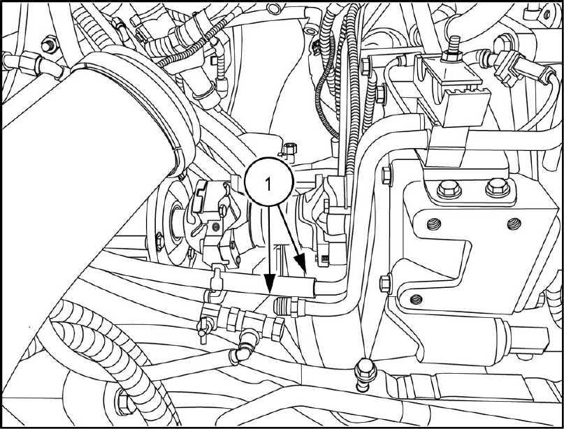
27. Disconnect the vacuum line (1) from the air intake lector elbow
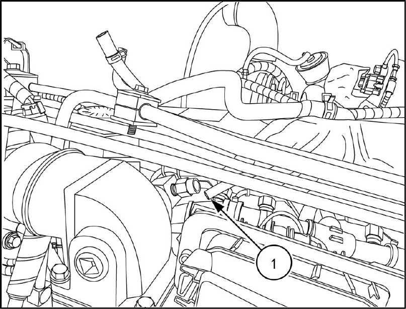
RAIL13TR01624AA
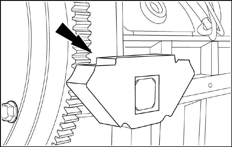
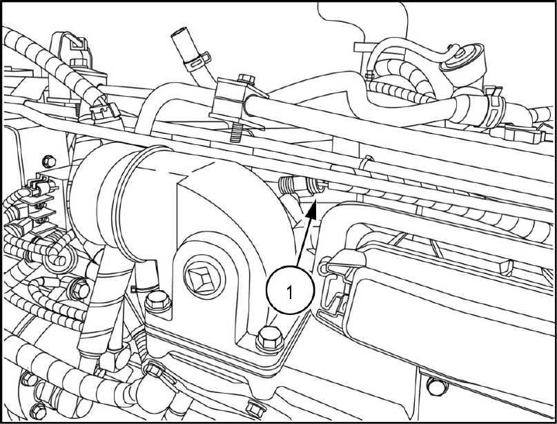
Disengage the P - clamp for the vacuum line from the fly wheel
RAIL13TR01621AA
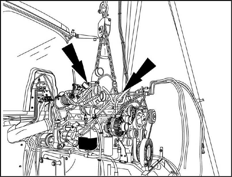
Attach appropriate lifting equipment the front and rear engine lifting
RAIL13TR01622AA
Engine - Engine and crankcase
47748092 26/09/2014 10.1 [10.001] / 1 1
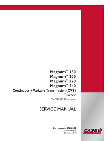
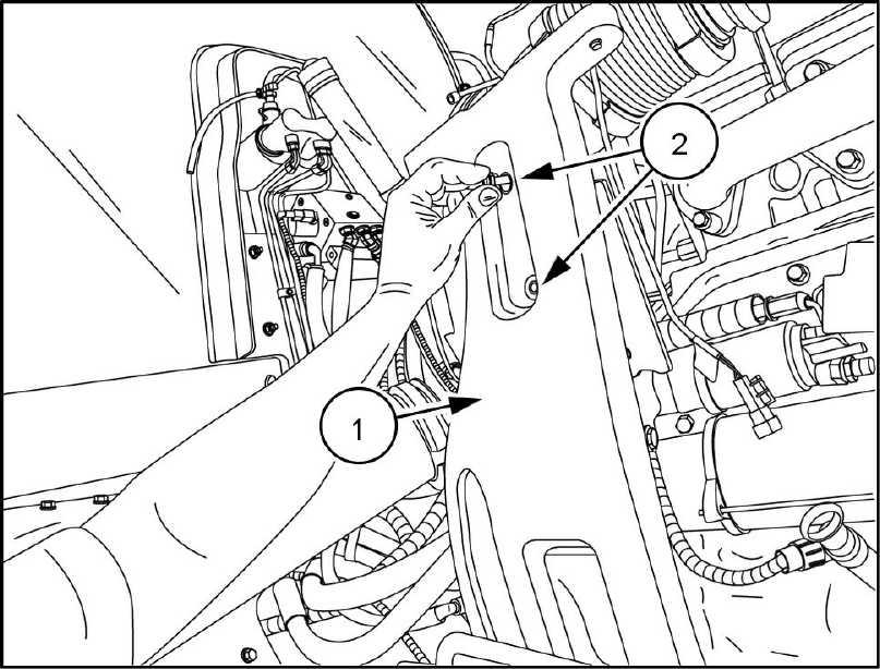
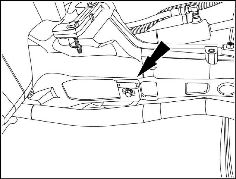
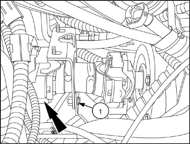
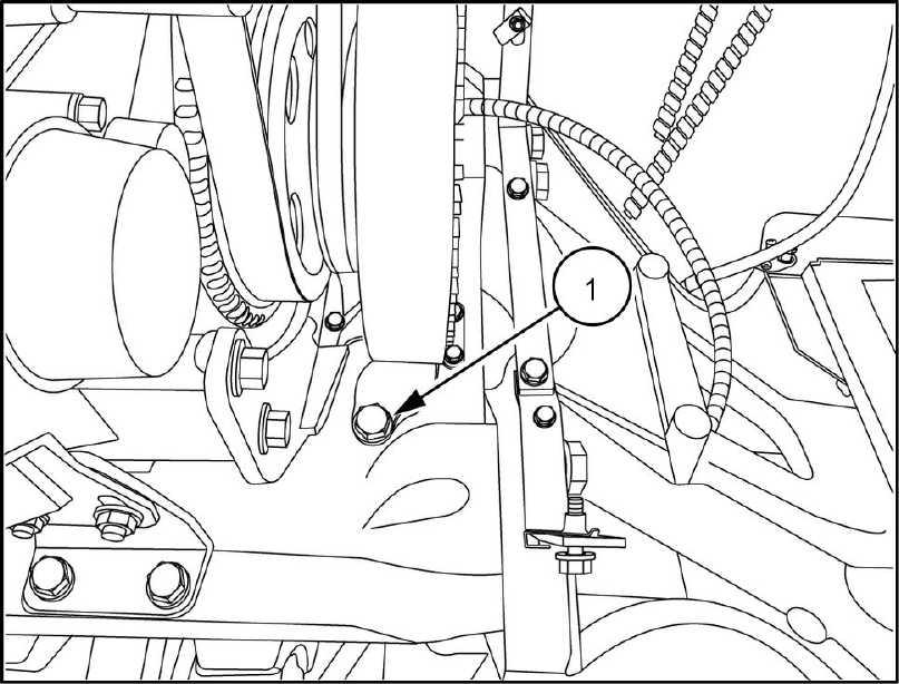
30. Remove the two bolts (1) from the isolation clamp for the front engine mount (right hand side
RAIL13TR01626AA
Raise the engine from the Check that all nesses and hoses are Remove the gine from the
Inspect the rear engine mounts for damage and / wear Replace necessary
RCPH07CCH166AAB
Inspect the front engine support (1) and isolation mount (2) for damage / and wear Replace necessary
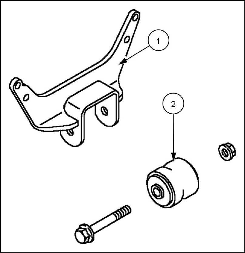
RCPH07CCH040BAB
Refer the engine repair manual for information supporting the engine during repair
Next operation:
Engine - Engine and crankcase
47748092 26/09/2014 10.1 [10.001] /
Engine - Engine and crankcase Engine - Install 47748092 26/09/2014 10.1 [10.001] /
Engine - Engine and crankcase
Engine - Install
Prior operation: Engine - Remove (10.001)
NOTICE: Check that all fittings are clean and free foreign matter during assembly Use new O - rings and lubricate them with petroleum jelly prior Properly support the engine and lower the engine into the front frame.
Retain tension the lifting equipment align the front isolation mount clamping Install the clamp and bolts. Remove the tension the lifting equipment.
T orque the engine mounting bolts - 106 ( - )
Remove the lifting
Install
1
RAIL13TR01627AA
2
RAIL13TR01626AA
the P - clamp (1) for the vacuum line the wheel
3 47748092 26/09/2014 10.1 [10.001] /
RAIL13TR01621AA
Connect the vacuum line (1) for the air intake collector elbow
Connect the two coolant lines (1) RAIL13TR01616AA 5
Connect the two hydraulic oil cooler lines (1) using new
Engine - Engine and crankcase
RAIL13TR01620AA 4
-
10.1 [10.001] /
O
RAIL13TR01615AA 6 47748092 26/09/2014