

85C 95C 105C Tractor SERVICE MANUAL Part number 47531618 English April 2013 Copyright © 2013 CNH Europe Holding S.A. All Rights Reserved.


transmission [ZxJX5xxxx] , Farmall 105C, with cab, with hi-lo transmission [ZxJX5xxxx] , Farmall 105C, with cab, with mechanical or power shuttle transmission [ZxJX5xxxx] , Farmall 105C, with cab, with mechanical or power shuttle transmission [ZxJX5xxxx] , Farmall 85C, less cab, with mechanical or power shuttle transmission [ZxJX5xxxx] , Farmall 85C, less cab, with mechanical or power shuttle transmission [ZxJX5xxxx] , Farmall 85C, with cab, with hi-lo transmission [ZxJX5xxxx] , Farmall 85C, with cab, with mechanical or power shuttle transmission [ZxJX5xxxx] , Farmall 85C, with cab, with mechanical or power shuttle transmission [ZxJX5xxxx] , Farmall 95C, less cab, with mechanical or power shuttle transmission [ZxJX5xxxx] , Farmall 95C, less cab, with mechanical or power shuttle transmission [ZxJX5xxxx] , Farmall 95C, with cab, with hi-lo transmission [ZxJX5xxxx] , Farmall 95C, with cab, with mechanical or power shuttle transmission [ZxJX5xxxx] , Farmall 95C, with cab, with mechanical or power shuttle transmission [ZxJX5xxxx]
Farmall 105C, less cab, with mechanical or power shuttle transmission [ZxJX5xxxx]
Farmall 105C, with cab, with mechanical or power shuttle transmission [ZxJX5xxxx]
Farmall 105C, less cab, with mechanical or power shuttle transmission [ZxJX5xxxx]
Farmall 105C, less cab, with mechanical or power shuttle transmission [ZxJX5xxxx]
Farmall 105C, with cab, with mechanical or power shuttle transmission [ZxJX5xxxx]
Farmall 105C, with cab, with mechanical or power shuttle transmission [ZxJX5xxxx]
Farmall 105C, with cab, with hi-lo transmission [ZxJX5xxxx]
Farmall 105C, with cab, with hi-lo transmission [ZxJX5xxxx]
Farmall 85C, less cab, with mechanical or power shuttle transmission [ZxJX5xxxx]
North America F5DFL413A*A001
North America F5DFL413A*A001
International Region F5DFL413A*A001
Europe F5DFL413A*A001
Europe F5DFL413A*A001
International Region F5DFL413A*A001
Europe F5DFL413A*A001
International Region F5DFL413A*A001
North America F5DFL413J*A001
Farmall 85C, with cab, with mechanical or power shuttle transmission [ZxJX5xxxx]
Farmall 85C, less cab, with mechanical or power shuttle transmission [ZxJX5xxxx]
Farmall 85C, less cab, with mechanical or power shuttle transmission [ZxJX5xxxx]
Farmall 85C, with cab, with mechanical or power shuttle transmission [ZxJX5xxxx]
Farmall 85C, with cab, with mechanical or power shuttle transmission [ZxJX5xxxx]
Farmall 85C, with cab, with hi-lo transmission [ZxJX5xxxx]
Farmall 85C, with cab, with hi-lo transmission [ZxJX5xxxx]
Farmall 95C, less cab, with mechanical or power shuttle transmission [ZxJX5xxxx]
Farmall 95C, with cab, with mechanical or power shuttle transmission [ZxJX5xxxx]
Farmall 95C, less cab, with mechanical or power shuttle transmission [ZxJX5xxxx]
North America F5DFL413J*A001
International Region F5DFL413J*A001
Europe F5DFL413J*A001
International Region F5DFL413J*A001
Europe F5DFL413J*A001
Europe F5DFL413J*A001
International Region F5DFL413J*A001
North America F5DFL413K*A001
North America F5DFL413K*A001
International Region F5DFL413K*A001
Farmall 95C, less cab, with mechanical or power shuttle transmission [ZxJX5xxxx]
Farmall 95C, with cab, with mechanical or power shuttle transmission [ZxJX5xxxx]
Farmall 95C, with cab, with mechanical or power shuttle transmission [ZxJX5xxxx]
Farmall 95C, with cab, with hi-lo transmission [ZxJX5xxxx]
Farmall 95C, with cab, with hi-lo transmission [ZxJX5xxxx]
Europe F5DFL413K*A001
Europe
F5DFL413K*A001
International Region F5DFL413K*A001
Europe F5DFL413K*A001
International Region F5DFL413K*A001
All maintenance and repair work described in this manual must be performed exclusively by CASE IH AGRICULTURE service technicians, in strict accordance with the instructions given and using any specific tools necessary. Anyone performing the operations described herein without strictly following the instructions is personally responsible for any eventual injury or damage to property.
Starting the system at low temperatures can damage the compressor. Only operate the air conditioner when the engine is hot and the temperature inside the cab is at least 20 °C (68.00 °F).
When disconnecting the hoses, close the ends with plastic caps to prevent foreign matter and humidity from getting inside the hoses.
Handle the thermostatic sensor carefully to avoid damage that may prevent efficient system operation.
Always use two spanners to unscrew the hose fittings to avoid twisting the fitting.
Do not use any type of engine oil to lubricate the compressor and the system.
Never leave the compressor oil container open, always make sure that it is tightly closed. If left exposed the oil will absorb humidity from the air and may, subsequently, damage the system.
Do not transfer compressor oil from the original container to another container.
Do not introduce any additives to the compressor oil. Any additional substances could contain elements which are incompatible with the chemical base of the refrigerant and thus alter its characteristics.
Check that the thermostatic sensor is correctly inserted in the fins on the evaporator to ensure efficient system operation.
Most accidents or injuries that occur in workshops are the result of non observance of simple and fundamental safety regulations.
For this reason, IN MOST CASES THESE ACCIDENTS CAN BE AVOIDED: by foreseeing possible causes and consequently acting with the necessary caution and care. Accidents may occur with all types of vehicle, regardless of how well it was designed and built. A careful and judicious service technician is the best guarantee against accidents. Precise observance of the most basic safety rule is normally sufficient to avoid many serious accidents.
DANGER: Never carry out any cleaning, lubrication or maintenance operations when the engine is running.
• Carefully follow specified repair and maintenance procedures.
• Do not wear rings, wristwatches, jewellery, unbuttoned or loose articles of clothing such as: ties, torn clothing, scarves, open jackets or shirts with open zips that may remain entangled in moving parts. It is advised to wear approved safety clothing, e.g: non slip footwear, gloves, safety goggles, helmets, etc.
• Do not carry out repair operations with someone sitting in the driver’s seat, unless the person is a trained technician who is assisting with the operation in question.
• Operate the vehicle and use the implements exclusively from the driver’s seat.
• Do not carry out operations on the vehicle with the engine running, unless specifically indicated.
• Stop the engine and ensure that all pressure is relieved from hydraulic circuits before removing caps, covers, valves, etc.
• All repair and maintenance operations must be carried out using extreme care and attention.
• Service steps and platforms used in a workshop or in the field should be built in compliance with the safety rules in force.
• Disconnect the batteries and label all controls to indicate that the vehicle is being serviced. Block the machine and all equipment which should be raised.
• Do not check or fill fuel tanks, accumulator batteries, nor use starting liquid when smoking or near naked flames, as these fluids are inflammable.
• Brakes are inoperative if manually released for repair or maintenance purposes. In such cases, the machine should be kept constantly under control using blocks or similar devices.
• The fuel nozzle should always be in contact with the filling aperture. Maintain this position until filling operations are completed in order to avoid possible sparks caused by the accumulation of static electricity.
• Only use specified towing points for towing the tractor, connect parts carefully.Make sure that all pins and/or locks are secured in position before applying traction. Never remain near the towing bars, cables or chains that are operating under load
• Transport vehicles that cannot be driven using a trailer or a low loading platform trolley, if available.
• When loading or unloading the vehicle from the trailer (or other means of transport), select a flat area capable of sustaining the trailer or truck wheels, firmly secure the tractor to the truck or trailer and lock the wheels in the position.
• Electric heaters, battery chargers and similar equipment must only be powered by auxiliary power supplies with efficient ground insulation to avoid electrical shock hazards.
• Always use suitable hoisting or lifting devices when raising or moving heavy parts.
• Take extra care if bystanders are present.
• Never pour gasoline or diesel oil into open, wide and low containers.
• Never use gasoline, diesel oil or other inflammable liquids as cleaning agents. Use non-flammable non-toxic proprietary solvents.
• Wear safety goggles with side guards when cleaning parts with compressed air.
• Limit the air pressure to a maximum of 2.1 bar (30.5 psi), according to local regulations.
47531618 07/05/2013 5
• Do not run the engine in confined spaces without suitable ventilation.
• Do not smoke, use naked flames, or cause sparks in the area when fuel filling or handling highly inflammable liquids.
• Never use naked flames for lighting when working on the machine or checking for leaks.
• All movements must be carried out carefully when working under, on or near the vehicle and wear protective equipment: helmets, goggles and special footwear.
• When carrying out checks with the engine running, request the assistance of an operator in the driver’s seat. The operator must maintain visual contact with the service technician at all times.
• If operating outside the workshop, position the vehicle on a flat surface and lock in position. If working on a slope, lock the vehicle in position and move to a flat area as soon as is safely possible.
• Damaged or bent chains or cables are unreliable. Do not use them for lifting or towing. Always use suitable protective gloves when handling chains or cables.
• Chains should always be safely secured. Ensure that fastening device is strong enough to hold the load foreseen. No persons should stop near the fastening point, trailing chains or cables.
• Maintenance and repair operations must be carried out in a CLEAN and DRY area, eliminate any water or oil spillage immediately.
• Do not create piles of oil or grease soaked rags as they represent a serious fire hazard; store them in a closed metal container. Before starting the vehicle or implements, make sure that the driver’s seat is locked in position and always check that the area is free of persons or obstacles.
• Empty pockets of all objects that may fall unobserved into the vehicle parts when disassembled.
• In the presence of protruding metal parts, use protective goggles or goggles with side guards, helmets, special footwear and gloves.
• Handle all parts carefully, do not put your hands or fingers between moving parts, wear suitable safety clothing safety goggles, gloves and shoes.
• When welding, use protective safety devices: tinted safety goggles, helmets, special overalls, gloves and footwear. All persons present in the area where welding is taking place must wear tinted goggles. NEVER LOOK AT THE WELDING ARC IF YOUR EYES ARE NOT SUITABLY PROTECTED.
• Where possible, remove the part or tool that requires arc welding from the tractor.
• Disconnect both battery leads. Isolate the cable ends to avoid contact with each other and the tractor.
• Position the welder ground clamp as near as possible to the area where welding is taking place.
• Remove the electronic control units located on the tractor if welding is to be carried out near these control units.
• Never allow welding cables to lay on, near or across any electrical wiring or electronic component while welding is in progress.
• Metal cables tend to fray with repeated use. Always use suitable protective devices (gloves, goggles, etc.) when handling cables.
• Never start the engine in confined spaces that are not equipped with adequate ventilation for exhaust gas extraction.
• Never place the head, body, limbs, feet, hands or fingers near fans or rotating belts.
• Always loosen the radiator cap slowly before removing it to allow any remaining pressure in the system to be discharged. Coolant should be topped up only when the engine is stopped or idle if hot.
• Never fill up with fuel when the engine is running, especially if hot, in order to prevent the outbreak of fire as a result of fuel spillage
• Never check or adjust fan belt tension when the engine is running. Never adjust the fuel injection pump when the vehicle is moving.
• Never lubricate the vehicle when the engine is running.
• If it is necessary to use auxiliary batteries, remember that both ends of the cables must be connected as follows: (+) with (+) and (-) with (-).
• Avoid short-circuiting the terminals. GAS RELEASED FROM BATTERIES IS HIGHLY INFLAMMABLE.
• During charging, leave the battery compartment uncovered to improve ventilation.
• Never check the battery charge using ”jumpers” (metal objects placed on the terminals).
• Avoid sparks or flames near the battery zone to prevent explosion hazards.
• Before servicing operations, check for fuel or current leaks. Eliminate any eventual leaks before starting work.
• Never charge batteries in confined spaces. Make sure that there is adequate ventilation in order to prevent accidental explosion hazards as a result of the accumulation of gases released during charging operations.
• Always disconnect the battery before performing any kind of servicing on the electrical system.
• Some fluid slowly coming out from a very small port can be almost invisible and be strong enough to penetrate the skin. Check for leaks using a piece of cardboard, NEVER USE HANDS.
• If any liquid penetrates skin tissue, call for medical aid immediately
• Serious skin infections may result if medical attention is not given.
• Use the specific tools when checking pressure values on the hydraulic system.
• Check that the tyres are correctly inflated at the pressure specified by the manufacturer. Periodically check possible damages to the rims and tyres.
• Stand away from (at the side of) the tire when checking inflation pressure.
• Only check pressure when the vehicle is unloaded and the tires are cold, to avoid incorrect readings as a result of over pressure.
• Do not re use parts of recovered wheels as incorrect welding or brazing may heat the material, causing it to weaken and eventually damage or break the wheel.
• Never cut, nor weld a rim with the inflated tyre assembled.
• When removing the wheels, lock both the front and rear vehicle wheels.
• Always position support stands when raising the vehicle, in order to conform to current safety regulations.
• Deflate the tyre before removing any object caught into the tyre tread.
• Never inflate tires using inflammable gases; this could cause an explosion and put operator safety at risk.
• Lift and handle all heavy parts using suitable lifting equipment and make sure that all slings and hooks are correctly secured.
• Handle all parts carefully during lifting operations, keep an eye on the personnel working near the load to be lifted. Never insert hands or fingers between parts, always wear approved accident prevention clothing (goggles, gloves and work boots).
• Avoid twisting chains or metal cables and always wear safety gloves when handling cables or chains.
• The refrigerant must be handled with great care in order to avoid personal injury; always use safety goggles and gloves.
• Liquid refrigerant can cause freezing of the skin and serious damage to the eyes, sometimes resulting in permanent blindness.
• Keep the refrigerant container away from heat sources. Heat will cause an increase in pressure of the refrigerant and could cause the container to explode.
• If refrigerant comes into contact with a naked flame or a hot metal surface it produces a toxic gas, which is dangerous if inhaled.
• In order to avoid accidents follow the simple precautions described below.
• The operation of emptying and charging the system must be carried out in a well-ventilated area, well away from any naked flames.
• During the charging and emptying operations, take the necessary precautions to protect the face and above all the eyes from accidental contact with refrigerant.
• In the event of an accident, proceed as follows:
- if refrigerant splashes into the eyes, wash immediately with a few drops of mineral oil, then wash them thoroughly with a solution of boric acid and water (one spoonful of acid in 1/4 cup of water) and seek medical assistance immediately.
- freezing of the skin caused by contact with liquid refrigerant may be treated by gradually warming the injured area with cold water, followed by the application of a greasy cream. Request medical assistance.
- the air conditioning system contains a mixture of refrigerant and oil under high pressure; under no circumstances loosen pipe fittings/unions or work on the pipes without having first drained the system.
- do not loosen or remove the compressor oil level check cap with the system pressurized.
- do not heat the refrigerant container. If the temperature exceeds 50 °C (122.00 °F) the pressure will increase very rapidly.
- keep the air conditioning system away from heat sources to prevent explosions as a result of an increase in pressure in the system piping.
• When transferring refrigerant from one container to another, only use homologated liquid refrigerant containers equipped with safety valves.
• Never fill liquid refrigerant containers over 80 % (80.0 %) of their maximum capacity.
• Do not modify the settings of safety valves and the control devices.
• Never connect the recovery/recycling and evacuation/charging stations to electrical power outlets with voltages other than those specified; do not leave the stations powered up unless they are to be used immediately.
Before commencing any work on the vehicle, always disconnect and isolate the negative lead from the battery, unless otherwise indicated for a specific operation (for example: an operation to be carried out with the engine running), on completion of which the negative lead should be disconnected before proceeding with the work.
At each adjustment, select the shims measuring them one at a time with a micrometer and summing the values obtained: do not measure the complete pack of shims all together or rely on the nominal values indicated on the shims as these could produce incorrect measurements.
For correct rotating shaft seal installation, proceed as follows:
• before assembly, allow the seal to soak in the oil it will be sealing for at least thirty minutes;
• thoroughly clean the shaft and check that the working surface on the shaft is not damaged;
• position the sealing lip facing the fluid; with hydrodynamic lips, take into consideration the shaft rotation direction and position the grooves so that they will deviate the fluid towards the inner side of the seal;
• coat the sealing lip with a thin layer of lubricant (use oil rather than grease) and fill the gap between the sealing lip and the dust lip on double lip seals with grease;
• insert the seal in its seat and press down using a flat punch; do not tap the seal with a hammer or mallet;
• whilst inserting the seal, check that it is perpendicular to the seat; once settled, make sure that it makes contact with the thrust element, if required;
• to prevent damaging the seal lip on the shaft, position a protective guard during installation operations.
Lubricate the O RING seals before inserting them in the seats, this will prevent them from overturning and twisting, which would jeopardise sealing efficiency.
Apply one of the following sealing compounds on the mating surfaces marked with an X: RTV 1473, RHODORSIL® CAF 1or LOCTITE PLASTIC GASKET
Before applying the sealing compound, prepare the surfaces as follows:
• remove any incrustations using a wire brush;
• thoroughly de grease the surfaces using one of the following cleaning agents: trichlorethylene, petrol or a water and soda solution.
When installing bearings it is advised to:
• heat the bearings to 80 ÷ 90 °C before fitting on the shafts;
• allow the bearings to cool before installing them.
When fitting split socket elastic pins, ensure that the pin notch is positioned in the direction of the force required to stress the pin.
Spiral spring pins do not require special positioning.
Wear limit values indicated for certain parts are recommended, but not binding. The terms “front”, “rear”, “right-hand” and “left-hand” (when referred to different parts) are intended as seen from the driving position with the tractor in the normal direction of movement.
External power supply cables should only be connected to the respective positive and negative cable terminals, using efficient clamps that guarantee adequate and secure contact. Disconnect all services (lights, windshield wipers, etc.) before starting the vehicle. If the vehicle electrical system requires checking, carry out operations with the power supply connected; Once checking is completed, disconnect all services and switch off the power supply before disconnecting the cables.
The tools that CASE IH AGRICULTURE propose and illustrate in this manual are:
• specifically researched and designed for use with CASE IH AGRICULTURE vehicles;
• necessary to make reliable repair;
• accurately built and strictly tested to offer efficient and long lasting working means. By using these tools, repair personnel will benefit from:
• operating in optimal technical conditions;
• obtaining the best results;
• saving time and effort;
• working in safe conditions.
Use solely genuine parts, which guarantee the same quality, duration and safety as the original parts as they are identical to the ones fitted during production. Only genuine parts can offer this guarantee.
When ordering spare parts, always provide the following information:
• tractor model (commercial name) and frame number;
• engine type and number;
• part number of the ordered part, which can be found in the “Microfiches” or the “Spare Parts Catalogue”, used for order processing.
[ZxJX5xxxx] , Farmall 105C, with cab, with mechanical or power shuttle transmission [ZxJX5xxxx] , Farmall 105C, with cab, with mechanical or power shuttle transmission [ZxJX5xxxx] , Farmall 85C, less cab, with mechanical or power shuttle transmission [ZxJX5xxxx] , Farmall 85C, less cab, with mechanical or power shuttle transmission [ZxJX5xxxx] , Farmall 85C, with cab, with hi-lo transmission [ZxJX5xxxx] , Farmall 85C, with cab, with mechanical or power shuttle transmission [ZxJX5xxxx] , Farmall 85C, with cab, with mechanical or power shuttle transmission [ZxJX5xxxx] , Farmall 95C, less cab, with mechanical or power shuttle transmission [ZxJX5xxxx]
, Farmall 95C, less cab, with mechanical or power shuttle transmission [ZxJX5xxxx] , Farmall 95C, with cab, with hi-lo transmission [ZxJX5xxxx]
, Farmall 95C, with cab, with mechanical or power shuttle transmission [ZxJX5xxxx] , Farmall 95C, with cab, with mechanical or power shuttle transmission [ZxJX5xxxx]
10.1 Farmall 105C, less cab, with mechanical or power shuttle transmission [ZxJX5xxxx] , Farmall 105C, less cab, with mechanical or power shuttle transmission [ZxJX5xxxx] , Farmall 105C, with cab, with hi-lo transmission [ZxJX5xxxx] , Farmall 105C, with cab, with mechanical or power shuttle transmission [ZxJX5xxxx] , Farmall 105C, with cab, with mechanical or power shuttle transmission [ZxJX5xxxx] , Farmall 85C, less cab, with mechanical or power shuttle transmission [ZxJX5xxxx] , Farmall 85C, less cab, with mechanical or power shuttle transmission [ZxJX5xxxx] , Farmall 85C, with cab, with hi-lo transmission [ZxJX5xxxx] , Farmall 85C, with cab, with mechanical or power shuttle transmission [ZxJX5xxxx] , Farmall 85C, with cab, with mechanical or power shuttle transmission [ZxJX5xxxx] , Farmall 95C, less cab, with mechanical or power shuttle transmission [ZxJX5xxxx] , Farmall 95C, less cab, with mechanical or power shuttle transmission [ZxJX5xxxx] , Farmall 95C, with cab, with hi-lo transmission [ZxJX5xxxx] , Farmall 95C, with cab, with mechanical or power shuttle transmission [ZxJX5xxxx] , Farmall 95C, with cab, with mechanical or power shuttle transmission [ZxJX5xxxx]
Engine - 10
Engine and crankcase - 001
Farmall 105C, less cab, with mechanical or power shuttle transmission [ZxJX5xxxx] , Farmall 105C, less cab, with mechanical or power shuttle transmission [ZxJX5xxxx] , Farmall 105C, with cab, with hi-lo transmission [ZxJX5xxxx] , Farmall 105C, with cab, with mechanical or power shuttle transmission [ZxJX5xxxx] , Farmall 105C, with cab, with mechanical or power shuttle transmission [ZxJX5xxxx] , Farmall 85C, less cab, with mechanical or power shuttle transmission [ZxJX5xxxx] , Farmall 85C, less cab, with mechanical or power shuttle transmission [ZxJX5xxxx] , Farmall 85C, with cab, with hi-lo transmission [ZxJX5xxxx] , Farmall 85C, with cab, with mechanical or power shuttle transmission [ZxJX5xxxx] , Farmall 85C, with cab, with mechanical or power shuttle transmission [ZxJX5xxxx] , Farmall 95C, less cab, with mechanical or power shuttle transmission [ZxJX5xxxx]
, Farmall 95C, less cab, with mechanical or power shuttle transmission [ZxJX5xxxx] , Farmall 95C, with cab, with hi-lo transmission [ZxJX5xxxx]
, Farmall 95C, with cab, with mechanical or power shuttle transmission
[ZxJX5xxxx] , Farmall 95C, with cab, with mechanical or power shuttle transmission [ZxJX5xxxx]
47531618 07/05/2013
Sump structural, cast iron
forced, with lobe pump
Pump drive from crankshaft
Oil filtration mesh screen on oil intake and filter cartridge on delivery line
Engine oil pressure switch operating pressures:
- contacts closing* with decreasing pressure.
- contacts opening* with increasing pressure.
* with the contacts closed the engine oil pressure warning light is on
0.2 bar (2.90 psi) 0.9 bar (13.05 psi)
Cooling coolant circulation
Radiator
Fill Capacity
Fan with viscous coupling, fixed to the relative pulley
with five rows of vertical pipes 16 l (4.23 US gal)
ø 520 mm (20.4724 in) intake, plastic with 10 blades
Coolant pump Centrifugal vane-type
Coolant thermometer
Temperature ranges corresponding to each section: – initial blue section
– red end section
colored scale divided into three sections
temperature okay
temperature excess 47531618
- start of opening via thermostat valve 80 °C (176.00 °F)
Temperature adjustment
Timing overhead valves operated by tappets, rods and rocker arms via the camshaft located in the engine block; the camshaft is driven by the crankshaft using straight-tooth gears Intake:
Clearance between valves and rocker arms with engine cold. The valve clearance is hydraulically controlled. Therefore, manual adjustment is not necessary.
Boost Turbocharged with intercooler
Air cleaning dual cartridge dry air cleaner, with clogged filter indicator with centrifugal pre-filter and automatic dust ejector
Fuel filtration by mesh prefilter on the supply pipe, suction line filter with water - fuel separator, low pressure filter and sensor.
Priming pumpInjection pump
Type
Nozzle type
Manual mounted on suction filter
High pressure Common Rail control unit HPCR - CP4.1
- 20300.00 psi) Filling:
Injection pressure
NOTE: *- For filter maintenance please refer to:( Diesel Particulate Filters (DPF) - Dynamic description manual regeneration of the diesel particulate filter (DPF) (55.408) )
1. Remove the hood (1) as indicated in Hood - Remove (90.100)
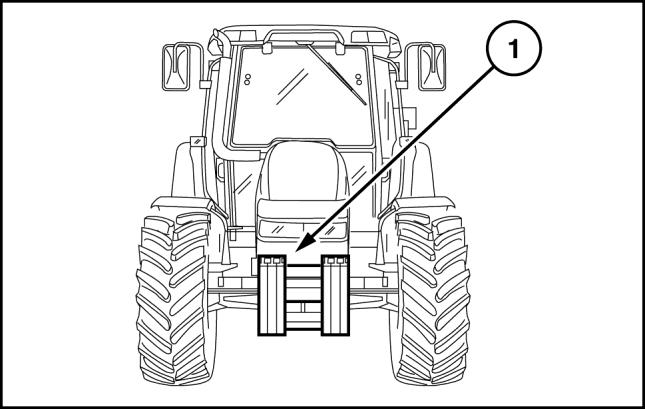
2. Remove the split pins, retaining pin and front ballast assembly (1) from the support.
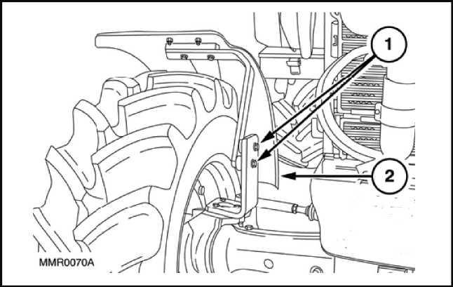
3. Unscrew the fixing screws (1) and remove the front wheel mudguards (2) (if applicable) Do this on both sides.
4. Remove the fixing bolts (1) and detach the engine left-hand side panel (2). Carry out the same operation for the right−hand side panel too. Remove the glove compartment.
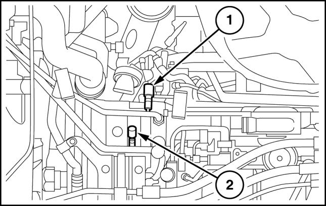
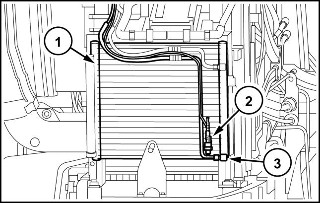
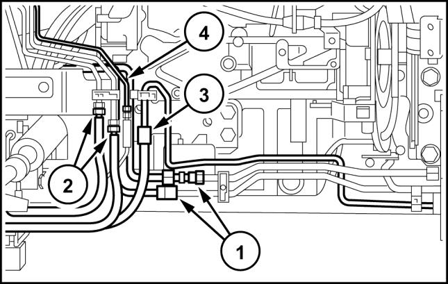
5. Recover the refrigerant from the system via the connections (1) and (2) using the specific tool 380000315. Detach the pipe (1), clear the section of brackets and clamps, move it onto the condenser ( (1), 5), detach the pipe (2), clear the section and take it to the cab.
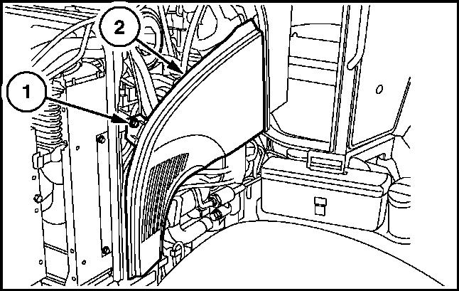
6. Subsequently go onto the front detach the lower pipe (3) on the condenser (1) free it from any straps or clamps, disconnect the sensor (2) and take it to the cab.
7. Drain the fuel from the tank by removing the bottom drain plug.
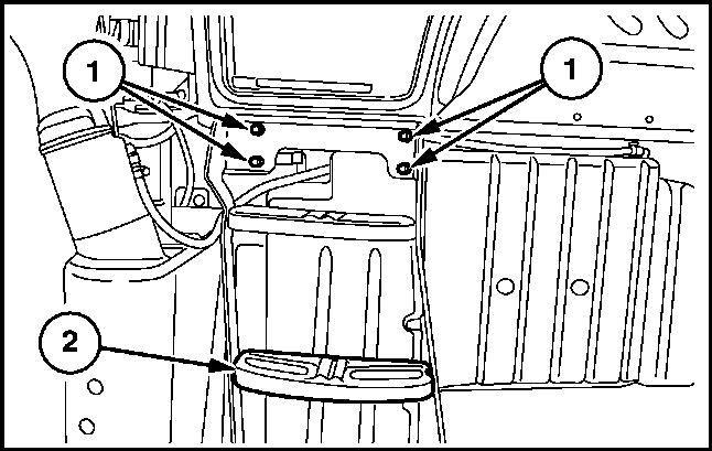
8. Unscrew the fixing bolts (1) and remove the righthand steps (2).
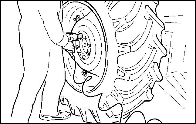
9. Raise the rear of the tractor with a hydraulic jack, put a mechanical stand under the reduction unit box, with a pneumatic gun remove the left-hand rear wheel retaining nuts, and subsequently take off the wheel.
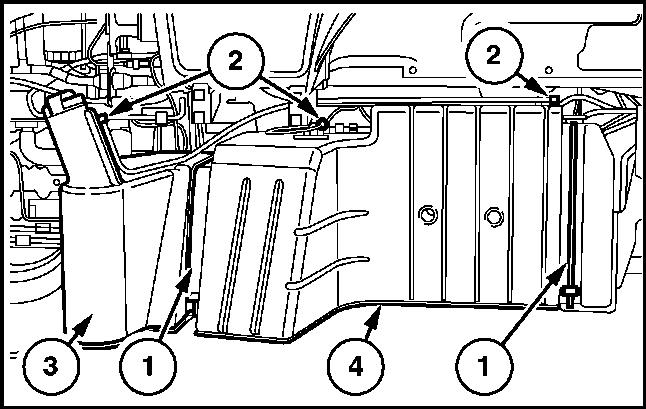
10. Detach the tank retaining straps (1), mark and detach the fuel pipes (2) and extract the fuel tank (3) Remove also the bottom tank guard (4)
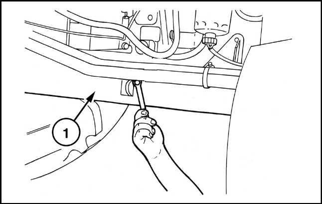
11. Unscrew the front central and rear retaining bolts on the front axle shaft guard, then remove the guard (1)
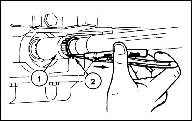
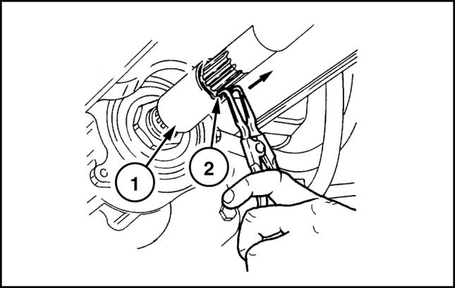
12. Remove the circlip (2) and move the front sleeve (1) in the direction indicated by the arrow until it is released from the groove on the front axle.
14. Take out the screws fixing the central support (1) of the propeller shaft and remove the shaft together with the support, remove also the shaft end float adjuster shim on the back.
15. Loosen the union of the cab heater radiator coolant return pipe, drain and collect the engine coolant.
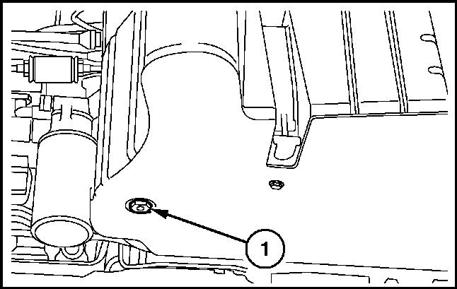
16. Take out the plug (1) and drain the oil from the gearbox transmission casing.
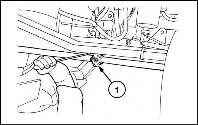
17. Loosen the hose (2)clamp DPF and detach the return pipe (1)

18. Loosen the fixing clamps (1) and extract the pipe from the turbine to the radiator intercooler (2) Carry out the same operation for the pipe from the radiator intercooler to the engine (3)
19. Loosen the clamp (2) fastening the air intake pipe to the turbine, then free the air cleaner (4) together with the support bracket (3) from the screws fixing it. Disconnect the oil vapor pipe (1) on the left-hand side of the engine at the level of the fuel pump; remove it all.
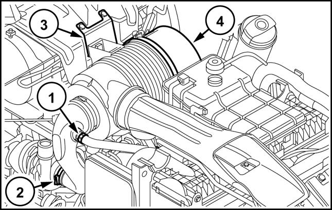
20. Free the air cleaner bracket - casing support (1) from the fixing screws and remove it.
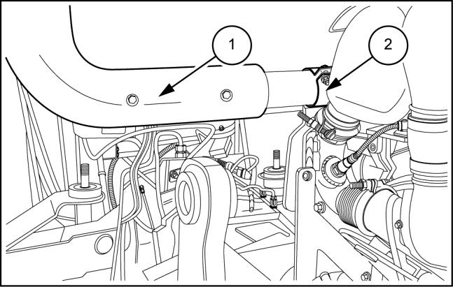
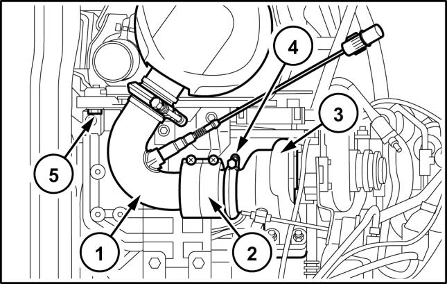
ATTENTION: The filter outlet union DPF (1) (2) at its terminal has a decoupler, that responds to temperature variations by changing length.
A small misalignment of the axis of the decoupler with respect to the axis of the turbine outlet (3) would produce an adjustment that would no longer be lengthwise, in line with the direction of the tractor, but abnormal transversal adjustment that would impair its durability.
21. Disconnect all the filter sensors, loosen the clamp (4), remove the entire filter together with the sensors, pressure sensing tubes, lambda probe and heat guards by undoing the four screws (5) fixing it on the bottom cradle.
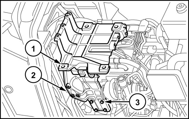
ATTENTION: Only if you have to work on the parts underneath the DPF support, it is advisable to remove the support.
The top part (1) and the right-hand part (2) should be removed as a block, when possible, by removing the fixing screws (3) to the right of the engine (these screws work on a vertical slot that allows the support (2) to take on various positions in height). Before disassembly, take some references on the position of the unit on the engine, so that during reassembly it is possible to restore it to the exact position in which it was first found.
22. To remove the rear guard, unscrew the two upper screws fastening the support (4) support (1), to remove the left support, (5) unscrew the two upper screws for the centering bushings and that secure the left bracket to the support (1) As regards removing the support (1) and (2) there are no special instructions to follow.
23. Detach the steering system pipes (1) and (2) the pipe delivering oil to the spool valve (3) Remove the fixings of the bracket (4) from the engine
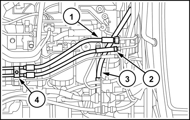
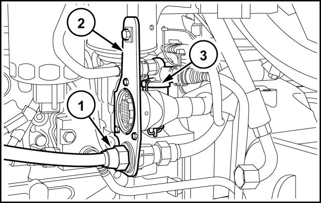
24. Detach the power steering spool valve outlet pipe on the gearbox spool valve (2), on the same filter detach the gearbox spool valve supply pipe (1).
Subsequently remove the filter together with the support (3)
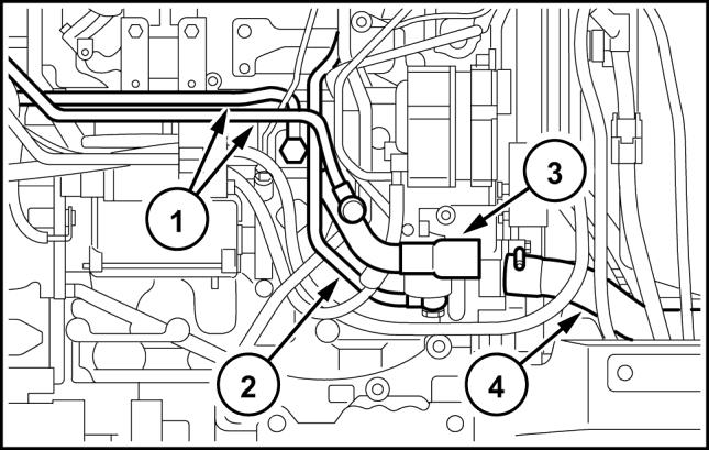
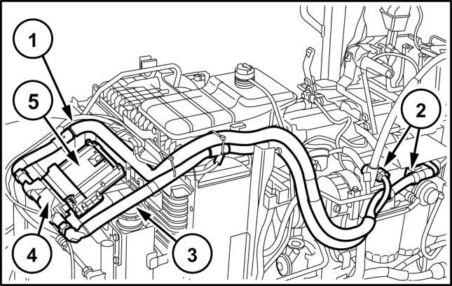
25. Disconnect the intake pipes from the pump (1) on the pump itself, the oil filter intake pipe from the transmission (2), on the junction under the transmission, at the height of the cab support.
Disconnect the delivery line to the lift (3) again at the height of the pipe (2)
Detach the delivery pipes (5) to the lift and to the power steering anti-cavitation tank (6) on the pump.
26. Detach the unit together with the filter (4), tank (6), support and the parts of piping disconnected previously.
27. Detach the high pressure - power steering pump unit.
28. Detach the pipes of the cooler (1), differential lock (3) and, if applicable, front braking assembly (4)
29. Free the pipes previously detached from the supports, brackets and clamps secured to the engine, do the same thing also for the pipes directed to the steering system cylinder (2)
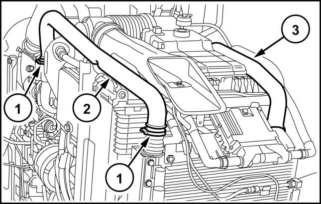
30. On the right-hand side, detach the cab heating pipes, (1), the pipe inserted on the engine sleeve. (3) coming from the expansion tank, then, loosen the clamps and, on the engine, detach the lower (4) and upper rubber sleeves joining radiator - engine.
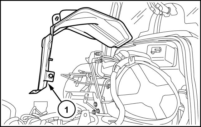
31. On the right-hand side, remove the guard (1) on the starter motor (2), disconnect the starting cable, the battery cut-off switch, the cable joining it to the alternator, also disconnect the alternator and the battery positive terminal, free all the wirings detached from the various clamps.
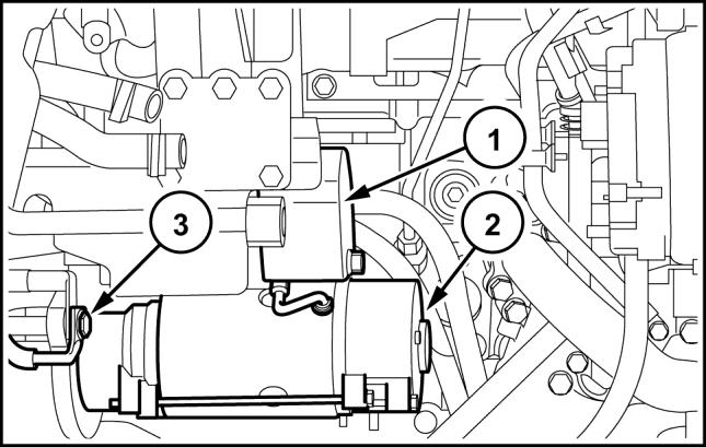
32. Detach the clamp bolt (3) then remove the ground cables of the engine and battery system, remove the other clamp bolts of the motor and remove it.
33. On the cable (1) of the FTP cable - engine interface detach all the connections (2), leave only those on the maxi fuse box and on the glow plug control unit, then, after cutting the clamps, collect the cable on the front near the control unit (5)
34. On the main engine cable (3) disconnect the connectors, starting from the one on the control unit (4), from the maxi fuse box and from the various switches and sensors located on the engine and, after freeing it from the clamps, move it onto the back at the height of the right-hand steps.
35. On the left-hand side disconnect the connector of the power cable of the cab (1), free it from the clamps and move it onto the maxi fuse box.
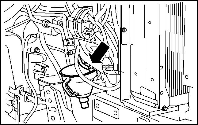
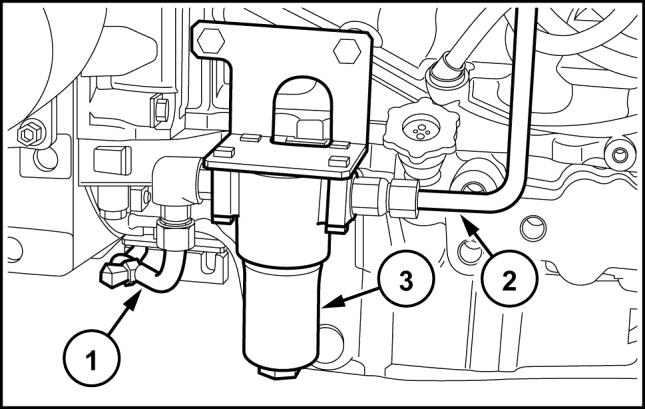
36. Detach the bracket (2) supporting the cab connectors, cab power and cup filter (3), disconnect the pipe that joins the latter to the mechanical priming pump on the sediment filter.
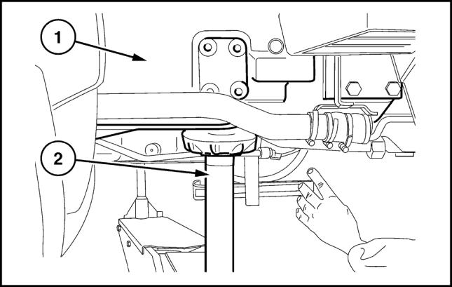
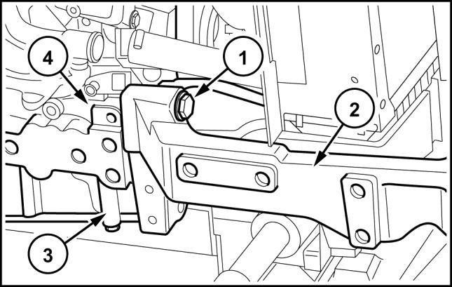
37. Hook the rear part of the engine onto a hoist using chains or ropes for the hoisting (apply two eye bolts, one to the right and one to the left, on the upper part of the flange containing the flywheel). Position a fixed stand (2) under the clutch housing (1) near the engine attachment flanging and apply the handbrake.
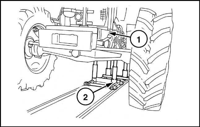
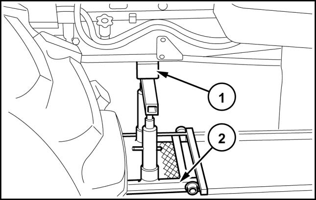 38. Position the movable tractor stand 380000569 (2) (1) with the bracket and adapter plate under the engine and place a wooden block in between the points of contact between the stand and engine. Wedge the axle to prevent swinging.
39. Remove the fixing screws (1) between the engine and the transmission.
40. Separate the engine (1) from the transmission with the tool 380000569 (2).
38. Position the movable tractor stand 380000569 (2) (1) with the bracket and adapter plate under the engine and place a wooden block in between the points of contact between the stand and engine. Wedge the axle to prevent swinging.
39. Remove the fixing screws (1) between the engine and the transmission.
40. Separate the engine (1) from the transmission with the tool 380000569 (2).
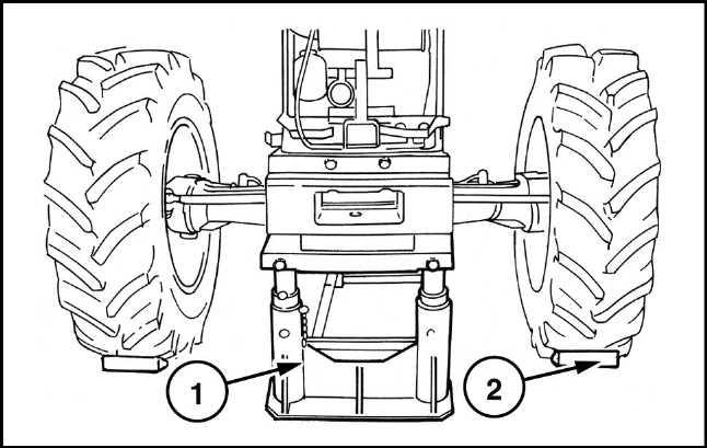
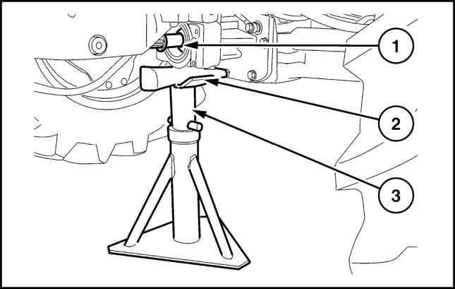
42. Position a fixed stand (3) under the support of the groove (1) of the front axle drive placing a wooden plug between parts (3) and (1)
43. Set a stand under the back of the engine so as to be able to release the hoist with the coupling device in full safety.
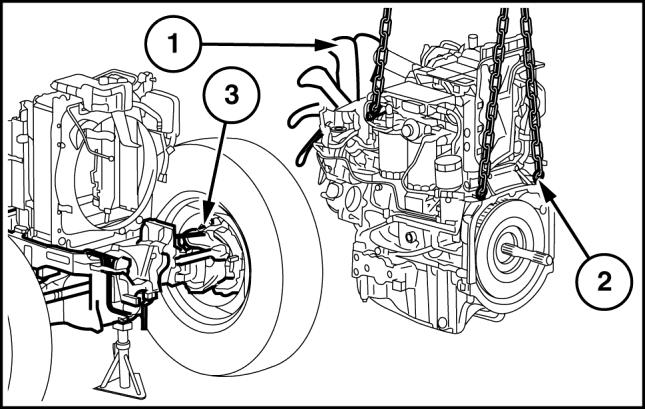
Add a rope or chain also on the front of the engine and take up the slack with the lifting device, keeping the engine balanced.
44. Remove the bolts (1) fastening the front axle support (2) to the engine. Remove the adjuster spacers for the support - monobloc (4) / sump (3)
45. Check that there are no brackets between the engine and the cooling assembly, detach the engine (2) from the front axle, (3) trying to avoid incorrect movements with the hoist in order not to damage the radiator fins (1) with the engine fan. Rest the engine (2) on a support.
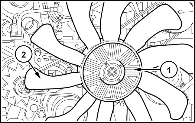
46. Remove the viscous coupling (1), where applicable, together with the fan (2)
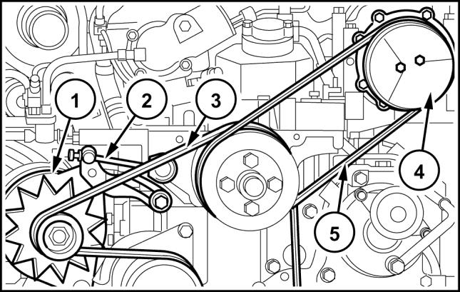
47. Loosen the compressor fixing screws (4), remove the belt (5), then remove the compressor.
48. Completely unscrew the belt tensioner (2), remove the flexible belt (3), then remove the alternator (1)
1. - Refit the flexible belt on the alternator and take up the slack according to the procedure in AlternatorTension adjust belt (55.301)
2. - Reposition the compressor and the relevant belt following this procedure:
- Reposition the compressor on the support and with the relevant pipe support secure it with the screws
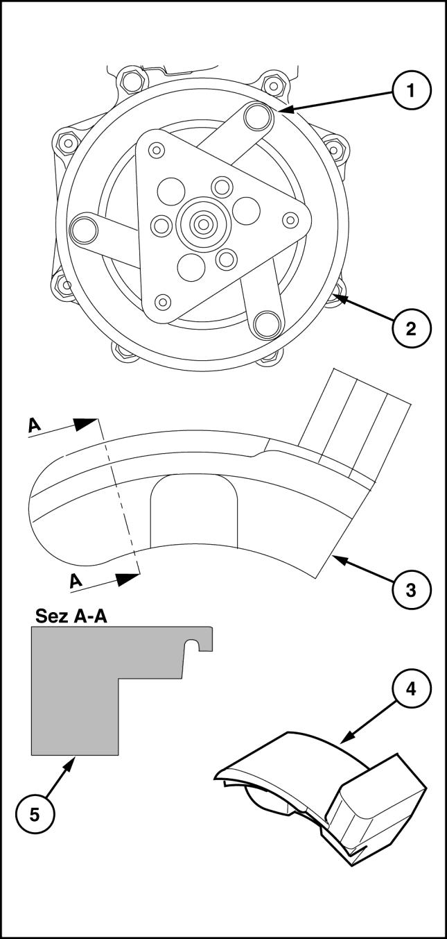
- To fit the belt polyv use the tool 380200011
(1). Compressor clutch actuator drive bracket.
(2). polyv belt pulley outer edge.
(3). Tool recess. It is used to drive the tool; this recess houses the bracket (1)
(4). Tail. Used to drive the polyv belt in the pulley seat.
(5). Hitching. Thanks to this recess, where the outer edge (2) is housed, the tool remains hitched to the compressor.
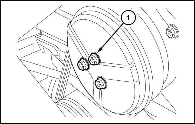
3. - Take out the bolts (1) and the related compressor clutch dust cover.
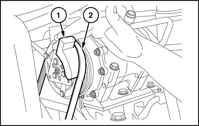
4. Make sure that the polyv (2) belt is perfectly housed on the fan pulley.
5. - Move the belt (2) near to the compressor pulley and, keeping the tool 380200011 under the belt, hook it onto the clutch of the compressor at the innermost part so as to slightly force the belt.
6.
- With your left hand on the fan and right hand on the tool, move both clockwise so as to take the belt onto the belt of the compressor.
- Put the dust cup back onto the compressor clutch and tighten the three screws taking care to spread a film of thread lock on the ends so they do not come unscrewed.
7. - Where applicable, reposition the viscous joint and the cooling fan.
8. - Apply the required torque settings ( see engine section)
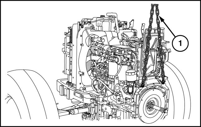
9. - Insert the three hooks of the chain in the eyelets on the engine and, using the hoist, lift the assembly off the platform support.
10. - Position the engine on the front axle, trying to avoid incorrect operations with the hoist so as not to let the engine fan damage the fins of the radiator, then join the two assemblies together with the four retaining bolts and the necessary adjuster spacers for the monobloc/sump support.
11. - Reposition the movable tool for dismantling tractors 380000569 under the engine and place a wooden block in between the point of contact between the tool and engine.
12. - With the aid of the hoist, place the engine on the tool 380000569 and remove the lifting eye bolts previously fitted on the rear of the engine.
13. - Remove the fixed stand previously positioned under the support of the groove of the drive of the front axle and the wooden plug.
14. - Remove the fixed U bolt fitted beforehand under the ballast support and the two wooden wedges locking the front wheels.
15. - Remove the old sealing paste from the two surfaces between the engine and clutch casing.
16. - Apply LOCTITE® 518 sealing compound on the engine and clutch casing mating surfaces.
17. - Put a wooden block under the right-hand rear wheel, make sure that the handbrake is fully applied and that all fixed and mobile stands are safely positioned.
18. - The installation phase described here requires the presence of two or three workers to use the movable tool for dismantling tractors 380000569 to move the engine/front axle assembly close to the gearbox.
19. - In the phase of installing the engine/front axle assembly to the gearbox, it is necessary to push on the front wheels, taking great care in the end phase of coupling over both the pipes and the cables/electrical connections to prevent crushing between the two bodies. During this phase, it is moreover necessary to turn the crankshaft with the aid of the radiator cooling fan to help the coupling between the sleeve and the drive shaft.
20. - Secure both assemblies by tightening all the bolts locking the engine to the gearbox.
21. - Disconnect the hoist chains, remove the U bolt previously fitted under the clutch casing and recover the movable tool for dismantling tractors 380000569.
22. - Refit the bracket supporting the cab connectors, cab power and cup filter, connect the pipe that joins the latter to the mechanical priming pump on the sediment filter.
23. - On the left-hand side, connect the cab power cable connector, take it onto the maxi fuse box and lock it with clamps.
24. - Return the main engine cable back into position, connect the connectors to the sensors and switches located on the engine, on the control unit and on the maxi fuse box, fasten the wiring with clamps.
25. - Lay out the FTP interface - engine cable on the machine, reconnect the various connections and secure the wiring with clamps.
26. - Fit the starter motor back on, then connect the two ground wires on the engine and battery system.
27. - On the right-hand side reconnect the battery positive cable and the wirings to the starter motor, battery cut-off switch and alternator. Fit the guard back onto the starter motor.
28. - Refit the two delivery and return lines to the cab heater and the pipe inserted on the lower sleeve coming from the expansion tank. Refit the upper and lower sleeves of the radiator engine connection. Secure the straps and clamps tightening the pipes.
29. - Reconnect the power steering spool valve oil filter together with the support. Reconnect the power steering oil drain pipe and the supply pipe to the spool valve of the gearbox.
30. - Refit the two oil delivery and return pipes to the cooler and secure them with the relevant clamp.
31. - Reassemble the power steering pump. Fit back on the transmission oil filter assembly and fix the screws, reconnect the delivery piping to the lift and to the power steering anti-cavitation assembly on the pump, the oil filter inlet from the transmission, and the two suction lines from the filter to the pump.
32. - Connect the pipes to the power steering cylinder and the supply to the spool valve.
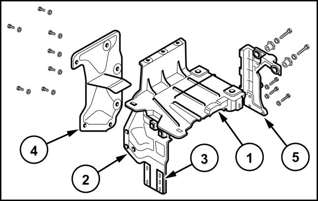
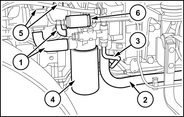
33. - If it was necessary to remove the DPF support proceed as follows:
1
Mount the upper support (1) on the right one (2) with the three Allen screws.
2 – Mount the left support (5) securing it to the engine with the three lower screws.
3 – Mount the assembly of the supports (1) and (2) to the engine with the four screws in position (3), respecting the reference marks made when dismantling.
4 – Secure the support (5) to the support (1) with the two upper screws with the two adjustment bushings.
5 – Mount the support (4) to the engine with the two lower screws, fasten the three left screws to the support (5) and with the two upper screws to the support (1)
34. - Fit the DPF filter assembly back on, returning the entire unit into position and fastening the four fixing screws of the assembly to the cradle.
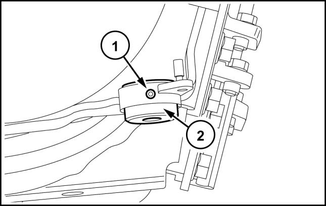
Observation:
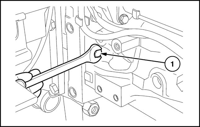
If after refitting the DPF filter you find a slight misalignment with the axis of the turbine, it is possible to make a correction. On the two screws fixing the filter to the cradle there are two threaded bushings (2) held in position by a grub screw (1) Loosen the grub screw with an Allen wrench, screw the bushing in or out by the amount necessary to correct the misalignment, retighten the grub screw and fix the support.
35. - Refit the upper bracket supporting the casing and secure it with the relevant screws.