General Dynamics NASSCO-Norfolk Pipe Welding Workmanship & Training Guide Process Owner-QA NIMS WI-Q-3030 All printed copies are uncontrolled The user is responsible for verifying that any printed copy of this document is current before use. This Tier III work Instructions is the Property of General Dynamics NASSCO-Norfolk Revision July 16, 2019


PIPE WELDING WORKMANSHIP & TRAINING GUIDE Process Owner QA WI Q 3030 NIMS Page 2 of 115 Revision 4/7/2021 TABLE OF CONTENTS 1.0 PURPOSE 5 2.0 SCOPE 5 3.0 RESPONSIBILITIES 5 4.0 DEFINITIONS 6 5.0 INSTRUCTIONS 6 5.1 Prerequisites 6 5.2 Workmanship ................................................................................................................... 7 5.3 Applicable Materials ...................................................................................................... 10 5.4 Cleanliness ..................................................................................................................... 10 5.5 Welding Equipment 11 5.6 Joint Design & Fit Up 12 5.7 Purge Requirements 12 5.8 Weld Requirements 15 5.9 Repair of Defects 21 5.10 Contaminated Tools .................................................................................................... 21 5.11 Records/Signatures ..................................................................................................... 21 5.12 Workmanship Samples ............................................................................................... 21 5.13 Acceptance Standard Classes ..................................................................................... 21 6.0 FORMS 22 7.0 ENCLOSURES 22 8.0 RELATED DOCUMENTS 22 9.0 REFERENCES 23 10.0 REVISIONS ....................................................................................................................... 23 ENCLOSURE A Fit Up Workmanship Requirements.............................................................. 24 ENCLOSURE A.1 Fit Up Workmanship Requirements Prior to Fit Up ........................... 24 ENCLOSURE A.2 Fit Up Workmanship Requirements Prior to Tacking ........................ 28 ENCLOSURE A.3 Fit Up Workmanship Requirements After Tacking (Recheck) 29 ENCLOSURE B Welder Workmanship 30 ENCLOSURE B.1 Welder Workmanship Tack Welds & In Process Welds 30 ENCLOSURE B.2 Welder Workmanship Excavations 32 ENCLOSURE B.3 Welder Workmanship Completed Weld .............................................. 34 ENCLOSURE C Special Workmanship Categories .................................................................. 40 ENCLOSURE C.1 Special Workmanship Categories Temporary Snipes ......................... 40
NIMS
PIPE WELDING WORKMANSHIP & TRAINING GUIDE Process Owner QA WI Q 3030
ENCLOSURE C.2 Special Workmanship Categories Welding Repair of Holes 40
ENCLOSURE C.3 Special Workmanship Categories Peening 41
ENCLOSURE C.4 Special Workmanship Categories Incorrect Filler Material 42 ENCLOSURE C.5 Special Workmanship Categories P 1 & P 2 Socket Joint Requirements ................................................................................................................................................... 43
ENCLOSURE D Guide to Standard Pipe Wall Thickness 48
ENCLOSURE E Workmanship Inspection Methods & Inspection Tools 49
ENCLOSURE F Welding Attribute Terms & Definitions 77
ENCLOSURE G Weld Joint Designs for Piping Systems 86
ENCLOSURE G Figure 1 Permanent Backing Ring/Permanent Backing Ring, Step 86 ENCLOSURE G Figure 2 Joint Configuration for Repair Welds ...................................... 87
ENCLOSURE G Figure 3 P 3, Butt Joint, Welded on Permanent Backing Ring, V Groove 88
ENCLOSURE G Figure 4 P 4, Butt Joint, Welded on Permanent, Integral Backing Ring, V Groove .................................................................................................................................. 89
ENCLOSURE G Figure 5 P 5, Butt Joint, Welded on Removable Backing Ring, V Groove 90
ENCLOSURE G Figure 6 P 7, Butt Joint, Welded on Removable Backing Ring, U Groove....................................................................................................................................... 91
ENCLOSURE G Figure 7 P 6, Butt Joint, Permanent Backing Ring, U Groove .............. 92 ENCLOSURE G Figure 8 P 10, Butt Joint, Welded Both Sides, V Groove 93 ENCLOSURE G Figure 9 P 11, Butt Joint, Welded Both Sides, Double V Groove 94 ENCLOSURE G Figure 10 P 13, Socket, Fillet Welded, Slip on Coupling 95 ENCLOSURE G Figure 11 P 14, Socket, Fillet Welded 96 ENCLOSURE G Figure 12 P 15, Socket Flange, Fillet Welded 97 ENCLOSURE G Figure 13 P 80, Bell End Fitting, Socket Weld Joint ............................. 98 ENCLOSURE G Figure 14 P 16, Welded Slip on Flange, Fillet Reinforced ................... 99
ENCLOSURE G Figure 15 P 17, Structural Sleeve For Piping Penetration ................... 100
ENCLOSURE G Figure 16 P 42, Double Fillet Welded Slip on Flange 101 ENCLOSURE G Figure 17 P 60, Branch Connection, Internal Fillet Welded 102 ENCLOSURE G Figure 18 P 61, Branch Connection, External Fillet Welded 103
ENCLOSURE G Figure 19 P 62, Branch Connection, Welded on One Side, External Fillet Reinforced ..................................................................................................................... 104
ENCLOSURE G Figure 20 P 63, Branch Connection, Welded Both Sides, External Fillet Reinforced 105
Page 3 of 115 Revision 4/7/2021
NIMS
PIPE WELDING WORKMANSHIP & TRAINING GUIDE Process Owner QA
ENCLOSURE G Figure 21 P 64, Branch Connection, Welded on Removable Backing Ring, External Fillet Reinforced 106
ENCLOSURE G Figure 22 P 66, Branch Connection, Welded on Removable Backing Ring, Internal Fillet Reinforced 107
ENCLOSURE G Figure 23 P 68, Internally Reinforced Fittings, Branch Connection, Welded on Both Sides, Single Bevel J 23 108
ENCLOSURE G Figure 24 P 70, Branch Connection with Pilot, Fillet Reinforced ....... 109
ENCLOSURE G Figure 25 P 71, Branch Connection With Plug, Fillet Reinforced ...... 110
ENCLOSURE G Figure 26 P 72, Branch Connection without Pilot, Fillet Reinforced .. 111
ENCLOSURE G Figure 27 P 73 and P 74, Joint Design and Fit up Dimensions, Consumable Insert Butt Joints 112
ENCLOSURE G Figure 28 Modified P 73 and Modified P 74, Open Root Butt Joint Design and Fit up Dimensions 113
ENCLOSURE G Figure 29 Transition Joints Between CRES and NiCu or CuNi 114
ENCLOSURE H Purge Duration Chart & Notes 115
4 of 115 Revision 4/7/2021
WI Q 3030
Page
WELDING WORKMANSHIP & TRAINING GUIDE
Owner QA
1.0 PURPOSE
This work instruction (WI) provides Pipe Fitters, Pipe Welders, Pipe Shop Foremen , and Weld Foremen with NASSCO’s workmanship guidance, inspection requirements, and acceptance criteria for fitting and welding piping systems. This workmanship guidance document is to be used for fabrication welding and repairs of castings, machinery, pipi ng, and pressure vessels to ensure workmanship requirements are met. This WI guidance is for the production worker (Pipefitters, Pipe Welders, and Weld Foremen) in conducting workmanship inspections only and is not for final VT inspection as required by WI Q 3009.
2.0 SCOPE
2.1 This instruction specifies the equipment, procedures, and acceptance standards for the workmanship inspection for fabrication welding and inspection, and casting inspection and repair for machinery, piping, and pressure vessels in accordance with (IAW) References A and B.
2.2 This WI provides detailed welding guidance/requirements that meet the requirements of NAVSEA Tech Pub S9074 AQ GIB 010/248, S9074 AR GIB 010/278, and Standard Item 009 12.
3.0 RESPONSIBILITIES
3.1
Trade Supervisor
3.1.1 Train Welders to the requirements of pipe welding and this WI.
3.1.2 Review work item, drawings, and correct weld procedure to identify correct material and welding process.
3.1.3 Provide the Fitter and Welder with the required technical documentation to perform their assigned work, such as work item, weld procedure specification, weld joint data sheet from Reference C, and drawings
3.2 Production Welder
3.2.1 Shall adhere to the requirements contained in and be familiar with the requirements within this WI.
3.2.2 Validate the provided technical documentation is applicable for the work assigned.
3.3 QA Welding and NDT Division
3.3.1 Perform periodic surveillance for conformity to this WI Surveillances shall be conducted semi annually (6) months at a minimum. Surveillances can and shall be performed at any time by management or QA personnel.
3.3.2 Provide technical support to production when needed.
PIPE
Process
WI Q 3030 NIMS Page 5 of 115 Revision 4/7/2021
4.0 DEFINITIONS
4.1 Standard terms and definitions are based on References A and B.
4.2 See Enclosure F for list of welding attribute terms and definitions applicable to the WI.
5.0 INSTRUCTIONS
5.1 Prerequisites
5.1.1
Training and Qualification Requirements
a. All Welders and welding procedure qualifications shall be trained IAW S9074 AQ GIB 010/248. Socket welds made on pipe wall thickness less than 3/16” (.187”) require the welder to be qualified IAW a thin wall socket weld procedure or a mock up test assembly of the production weld.
b. Personnel performing fit up or welder workmanship inspections shall be qualified by successfully completing pipe welding and fit up workmanship inspection IAW this WI.
5.1.2 All welding shall be accomplished IAW S9074 AR GIB 0101/278. All NDT shall be accomplished using procedures qualified to T90749074 AS GIB 010/271 and evaluated to MIL STD 2035.
5.1.3 Production shop conducting pipe fitting and welding operations will ensure they have a defined work scope based on the contracted work specification item for the contract they are working. If the scope of work or any aspect of the fitting/welding process is not able to be performed as defined in the work specification item and NAVSEA Standard Item 009 12 they are to stop work CFR process. Prior to initiating the CFR it is recommended the production shop contact the QA department to validate the constraint cannot be addressed through some other process.
5.1.4 Production shop Foreman/Supervisor will ensure the production fitter or welder is provided the appropriate weld procedure specification (WPS) joint design technical data sheet from MIL STD 22D Reference C. They will ensure the production personnel being assigned are qualified to conduct the assigned welding and understand the critical elements of the WPS and the joint design technical data sheets. The Foreman/Supervisor will provide the production Fitters/Welders with the appropriate drawings as applicable for work being done. If work is covered by a 009 09 PCP requirement they will maintain and have the PCP at the job site while conducting fitting or welding.
5.1.5 Maintaining this WI on the job site It is required that the Production Fitter and Welder carry this WI with them to the job site (onboard ship or away from NASSCO production shops) along with the items discussed in the previous paragraph to ensure workmanship requirements are being met. Workers in production shops at NASSCO must have readily available
WI Q 3030
Page
PIPE WELDING WORKMANSHIP & TRAINING GUIDE Process Owner QA
NIMS
6 of 115 Revision 4/7/2021
PIPE WELDING WORKMANSHIP & TRAINING GUIDE
access to this WI to ensure workmanship requirements are being met. Foreman and Supervisors must be well versed in the workmanship requirements.
5.1.6 The production Pipe Fitter and Pipe Welder will document specific inspection attributes for each weld joint while conducting pipe welding.
5.2 Workmanship
There are eight enclosures attached to this WI that provide workmanship requirements as required in References A F. Production Pipe Welders and Pipe Fitters will use these enclosures to ensure workmanship requirements are met IAW Reference A C. These enclosure are:
5.2.1 Enclosure A Fit Up Workmanship The enclosure contains fit up workmanship information: joint design, end preparation, material cleanliness, material acceptance, and fit up requirements. This section is divided into three areas based on when the inspections are done, as follows:
a. Section A.1 is Prior to Fit up
b. Section A.2 is Prior to Tacking
c. Section A.3 is Recheck A.1 and A.2 requirements after Tacking
5.2.2 Enclosure B Welder Workmanship This enclosure contains part of the welder workmanship information that a welder needs to verify the weld has been made to requirements of the technical publication. It is divided into three sections, as follows:
a. Section B.1 is Tack Welds and In Process Welds
b. Section B.2 is Excavations (Back Gouge and Repairs) c. Section B.3 is Completed Weld and addresses the inspection and acceptance criteria for the following:
3030
Page
Process Owner QA WI Q
NIMS
7 of 115 Revision 4/7/2021
Arc Strikes Burn Through Crack Crater Pits Incomplete Fusion Incomplete Penetration Overlap Oxidation Sharp Irregularities Slag Butt Weld Reinforcement
Cleanliness
Corner Melt
Edge Melt (Sockets)
End Melt
Fillet & Socket Weld Size
Melt Through
Arc Strike Removal Sites, Nicks, Gouges, Fabrication Scars, Grind Marks and Surface Roughness
Offset Pipe, Misalignment Other than Pipe
Porosity
Root Contour (Concavity and Convexity)
Weld Spatter
Undercut
Seal Off and Wrap Around Welding
5.2.3 Enclosure C Special Workmanship Categories This enclosure contains information regarding special workmanship categories or guidance to address special situations. It contains the following:
a. Section C.1 is Temporary Snipes b. Section C.2 is Welding Repair of Holes
c. Section C.3 is Peening d. Section C.4 is Incorrect Filler Material Removal
e. Section C.5 is P 1 & P 2 Socket Joint Requirements & Overlapping Welds
5.2.4 Enclosure D Guide to Standard Pipe Wall Thickness This enclosure contains a table that has pipe chart/standard wall thickness requirement information.
5.2.5 Enclosure E Workmanship Inspection Methods & Inspection Tools This enclosure contains information regarding inspection methods and recommended tools to be used for these inspections. It provides pictures that illustrate the proper use of the inspection and measurement tools to conduct the following types inspection of welding/fitting attributes:
a. Bottom Radius
b. Corner Melt c. End Melt d. Fabrication Scars
WI Q 3030
Page
PIPE WELDING WORKMANSHIP & TRAINING GUIDE Process Owner QA
NIMS
8 of 115 Revision 4/7/2021
WELDING WORKMANSHIP & TRAINING GUIDE Process Owner QA
e. Plating Misalignment (or Offset) f. Piping Offset g. Re Entrant Angle h. Root Surface Convexity or Concavity i. Undercut
j. Weld Size (Reinforcement or underfill Butt Welds) k. Weld Size (Fillet) l. Weld Size (Socket) m. Wall Thickness n. Angular Misalignment o. Bevel Angle p. J Groove Radius q. Land Thickness (Root Face) r. Counter bore Taper s. Grinding Reference Line t. Tack Weld Reference Line u. Diametrical Clearance v. Consumable Insert Ring End Gap w. Consumable Insert Ring Side Clearance x. Consumable Insert Ring Diametrical Clearance y. Root Opening z. Sharp Irregularities aa. NDT Reference Arrow bb. Keyholing cc. Weld Inspection Tools dd. Completed Fillet Weld Size Inspection ee. Completed Branch Connections with Fillet Reinforcement
5.2.6 Enclosure F Welding Attribute Terms & Definitions This enclosure contains terms and definitions of welding terms.
5.2.7 Enclosure G Weld Joint Designs for Piping Systems This enclosure contains information regarding fit up requirements related to various joint details as shown in MIL STD 22D and all related notes.
WI Q 3030
Page
PIPE
NIMS
9 of 115 Revision 4/7/2021
PIPE WELDING WORKMANSHIP & TRAINING GUIDE
Q 3030 NIMS
Process Owner QA WI
5.2.8 Enclosure H Purge Duration Chart & Notes This enclosure contains information regarding the time required for six volume changes at a flow rate of 30 cfh.
5.3 Applicable Materials
5.3.1
Base Materials
a. New base materials shall meet the requirements of the applicable material specification listed in Table I of S9074 AR GIB 010/278.
b. New material conforming to equivalent specifications may be used when authorized by the work specification authorization documents or the specified applicable drawing.
5.3.2 Filler Materials
a. Filler material shall be as specified on the applicable WPS and verified it is applicable for the base materials being used.
b. Level 1 filler materials will be certified Level 1 IAW 0948 LP 045 7010 for joints that require certification to Level 1 requirements.
NOTE: Level 1 filler material receipt inspection, storage, issue, and control shall be IAW NASSCO Norfolk Work Instruction WI Q 3003 Level 1 Material Control (MIC).
c. Non levelized filler material storage, issue, and control shall be IAW NASSCO Norfolk WI Q 3007 Filler Metal Control.
5.4 Cleanliness
5.4.1 Cleaning Tools Grinding, polishing, filing, deburring, and brushing tools shall be clean and shall not have been used on aluminum, lead, or materials containing lead or lead compounds, or other low melting point materials. To prevent contamination of corrosion resistant alloys by free iron, tools to be used on corrosion resistant alloys shall have been used on carbon steel or low alloy steels.
a. Grinding and polishing shall be performed with aluminum oxide or silicon carbide grinding wheels or discs that will assure a cleanly cut surface.
b. Brushing shall be performed with clean, corrosion resistant steel brushes. (Carbon steel brushes may be used on carbon steel materials only). Power driven wire brushes shall not be used on surfaces that are to be liquid penetrant inspected (PT) unless the resulting surface is removed using an approved abrasive material prior to performing the inspection. Requirements for wire brushes shall be as follows for the specified base material:
Page
10 of 115 Revision 4/7/2021
PIPE WELDING WORKMANSHIP & TRAINING GUIDE
BASE MATERIALS
Carbon steel (S 1, S 2)
WIRE BRUSH MATERIAL
Steel or stainless steel (See Note 1)
Low alloy and high alloy steels (S 3 through S 11) Stainless steel (See Notes 1 &2) Nonferrous materials (all other S numbers)
NOTES:
Stainless steel (See Notes 1 & 2)
1. Wire brushes previously used on aluminum or low melting temperature materials shall not be used.
2. Wire brushes previously used on low alloy steels or low melting point temperature materials s hall not be used.
c. Filing or deburring shall be performed with carbide or tool steel tools.
d. Stainless or tool steel slag picks may be used for removal of slag or scale.
5.4.2 Base Material The weld area and a minimum of one (1) inch on each side of all joint surfaces shall be free of scale, metallic oxides, paint, oil, grease, and other impurities.
5.4.3 Filler Material All bare rod and insert material shall be free of metallic oxides, oil, grease, or other foreign materials. Cleaning may be accomplished using a suitable abrasive material followed by wiping down with acetone or ethanol (alcohol).
5.4.4
Interbead Cleaning
a. Consumable insert and open root (root layer) shall have all surface oxides removed by hand wire brushing. Visible defects shall be removed using carbide burrs or files prior to depositing additional passes.
b. SMAW and GTAW processes shall have slag or scale on each weld bead removed prior to depositing the next bead. Cleaning may be accomplished using slag picks followed by wire brushing. Visible surface defects and sharp bead valleys shall be removed by grinding or burring.
5.5 Welding Equipment
5.5.1 GTAW power supply shall be capable of producing sufficient arc initiation and current controls for stops and starts. Current controls for arc initiation and arc decay shall be set for a minimum of five (5) seconds.
5.5.2 GTAW torch shall be an air or water cooled type, capable of efficient operation within the current range specified, have a cup size as specified on the WPS, and when possible, equipped with a gas lens.
5.5.3 GTAW flowmeter shall be an instrument capable of sustaining the gas flow specified on the WPS.
5.5.4 GTAW electrode shall be as designated on the WPS, typically 2% thoriated tungsten shaped to a taper equal to 1.5 to 4 times the electrode diameter with an approximately 1/32”spherical radius on the end. Electrode extension and
Page
Process Owner QA WI Q 3030 NIMS
11 of 115 Revision 4/7/2021
NIMS Page 12 of 115 Revision 4/7/2021
PIPE WELDING WORKMANSHIP & TRAINING GUIDE Process Owner QA
electrode diameter will be as specified on the WPS. The tungsten shall conform to the requirements of AWS A5.12.
5.5.5 SMAW equipment shall use suitable electrode holders, leads, ground connection, work handling equipment, etc., all of which shall be kept in good condition and maintained within acceptable safety standards.
5.5.6 Other Equipment
a. Ground An adjustable ground clamp that is free of spatter, raised metal, etc., that could damage the piping or components. Grounding or equipment for shipboard use shall be IAW NAVSEA Standard Item 009 12.
b. Ammeters Calibrated ammeters shall be used to set and check welding current values specified in the WPS. Ammeters should be connected to the electrode lead only and should be connected at a point less than 25 feet from the welding torch or rod holder.
c. Contact Pyrometer Calibrated fluke 52 type with 0°F to 500°F scale or equivalent.
d. Infrared Pyrometers Must be calibrated and meet the same requirements of the contact pyrometer.
e. Oxygen Analyzer Shall be an instrument capable of measuring the oxygen content limits specified in this manual.
f. Dewpointer Shall be a Shaw automatic dewpoint meter or equivalent where the value of at least 40°F shall be obtained. The time it takes to reach 40°F should be noted and Torch shall be prepurged that time to help ensure no porosity in the starts.
5.6 Joint Design & Fit Up
Joint design and fit up dimensions shall be IAW Enclosure A.1. Enclosure G shows the applicable joint design sketches (Figure 1 thru 29) of this manual.
5.7 Purge Requirements
(Consumable Insert and Open Root Butt Joints)
5.7.1 General Requirements Purging is required for all consumable insert and open root piping welds. When using open root piping weld procedures qualified without purge, purging is not required. The purge shall be established prior to tacking and shall be maintained until the filler metal has been deposited to a thickness of 3/16” or three layers, whichever is greater. The two basic methods of purging are: (1) volume change method, and (2) continuous flow method.
5.7.2 Valve Line Up Purge path and valve line up for shipboard welding shall be as specified by shop personnel and Shop Foreman. Valve line up and purge path requirements for assemblies not connected to the ship’s system may be established by the shop.
3030
WI Q
PIPE WELDING WORKMANSHIP & TRAINING GUIDE Process Owner QA
5.7.3 Volume Change Method This method is the technique where the purge gas is allowed to flow for at least six volume changes within the purge chamber prior to welding.
a. The volume change method shall be used only on known dry systems/components. Known dry systems are those that have either (1) not been wetted, or (2) been proven dry by visual inspection.
b. When using the volume change method, the oxygen content should be analyzed at the purge outlet or the weld joint prior to welding. As a minimum, the oxygen content must be analyzed downstream of the purge panel prior to connecting the panel to the system.
c. See Enclosure H for the purge chart for volume change duration chart and guidelines for determining six volume changes.
5.7.4 Continuous Flow Method When the path cannot be proven dry, the purge gas shall be analyzed, prior to welding, at the joint or purge gas exit for oxygen. Moisture (dewpoint) checks shall be made for Ni Cu, Cu Ni, and nickel chromium iron (inconel) materials when the continuous flow method is used.
5.7.5 Detailed Requirements for Purging The following purge requirements shall be observed during welding unless otherwise specified by welding engineering:
a. Purge inlet pressure 1” water or less, as measured by a calibrated magnahelic differential pressure gauge connected to the purge inlet.
b. Outlet oxygen content less than 1% as verified per previous step.
c. Weld area and purge path shall be free of moisture.
d. Unwelded joints shall be made tight by sealing with pressure sensitive tape.
e. Fixtures for connecting the hose shall be air tight.
f. Tubing used for connecting argon tanks to piping shall be copper, Tygon, Nylo Braid, or equivalent. Copper tubing shall be used whenever possible. Rubber hoses shall not be used.
g. All tacks shall be adequately purged.
h. All branches shall either be blocked off or purged out and all openings in the branch lines sealed where possible.
i. Purge gas dewpoint shall be verified when aluminum or titanium materials are to be welded. See the appropriate WPS for details.
j. Until 3/16” or the root and two layers have been deposited, purge shall be maintained and checked with an oxygen analyzer to verify an oxygen level of less than 1%, by shop or QA personnel at the following intervals:
WI Q 3030
Page
NIMS
13 of 115 Revision 4/7/2021
PIPE WELDING WORKMANSHIP & TRAINING GUIDE
Process Owner QA
Prior to tacking.
Prior to welding.
At frequent intervals during welding.
After any delay or shift change.
When purging has been stopped or interrupted for any reason.
NOTE: Purging shall be maintained during the entire welding evolution for titanium materials.
5.7.6 Verification of Purge Oxygen Analysis
a. Preferred Method Use an oxygen analyzer to verify that the oxygen content of the purge gas at the purge outlet is less than 1% with purge inlet pressure 1” water or less.
b. Alternate Method This method for verification of the oxygen content of the purge gas may be used if verification is not possible at the purge exit, or the accuracy of the readings at the purge exit are questionable:
After fit up, construct an air tight enclosure around the joint using tape or polyethylene. Provide a small vent opening to allow continuous flow of purge gas. Obtain samples of purge gas by placing needle or hose end inside the enclosure.
For the volume change method, analyze oxygen content downstream of the purge panel prior to connecting the panel to the system.
5.7.7
Verification of Purge
Moisture Analysis The dewpoint is required to be measured only when using the continuous flow method and when welding NiCu, CuNi, and NiCrFe materials.
a. Preferred Method Use a dewpointer to verify that moisture in the gas does not exceed the limits specified in previous paragraph. Measure the dewpoint at the exit of the purge path.
Positive connections must be made between the piping, tube, hoses, and the dewpointer. This includes the use of metal pipe caps with fittings brazed or soldered and hose clamps, when possible.
b. Alternate Method Use the following method for verification of the dewpoint of the purge gas when verification is not possible at the purge exit, or the accuracy of the dewpoint readings taken at the exit of continuous flow path is questionable.
Dewpoint may be checked at the assembled joint by constructing an air tight enclosure of several layers of polyethylene sheets wrapped tightly around the joint and taped securely at the extremities with vinyl backed cloth tape. Provide a small vent
WI Q 3030
NIMS Page 14 of 115 Revision 4/7/2021
NIMS Page 15 of 115 Revision 4/7/2021
PIPE WELDING WORKMANSHIP & TRAINING GUIDE Process Owner QA
opening in the enclosure to allow for the poly and gas samples to be withdrawn for checking. All joints must be tightly taped to prevent any leakage of air into the system and the needle must be sil brazed to the adapter. The purge inlet pressure must indicate 1” of water or less for an effective dewpoint to be taken.
Oxygen content of the purge gas may be checked in the same manner.
c. The acceptable upper limits of dewpoint are listed below:
NiCu (Monel) 20°F
CuNi 20°F
NiCrFe (Inconel) less than 0°F
NOTE: The dewpoint shall be maintained equal to or less than the above limits during welding.
NOTE: Dewpoint checks are not required for carbon steel and CRES.
NOTE: Reverification of the dewpoint is not required after flowing of the insert is completed.
5.8 Weld Requirements
5.8.1 General Information Protect surrounding area beyond weld prep from arc strikes and weld spatter by covering with heat resistant cloth. The protective material should extend within one inch of each edge of the Joint preparation. Inspect the area for preexisting damage NSI 009 06 and report any preexisting damage via the CFR system. Ensure the requirements of NSI 009 06 is followed to protect the area.
5.8.2
Area of Inspection
a. Prior to welding, the area of inspection shall include a minimum of 1” of base metal from the expected weld toes.
b. During welding (i.e., after tacks and between weld beads/layers), the area of inspection shall include a minimum of 1/2” of base metal from the expected weld toes.
5.8.3 Minimum Lighting Requirements Inspections shall be performed with adequate lighting. Adequate lighting is defined as a minimum of 50 foot candles on the surface being inspected. A standard 2 cell flashlight with good batteries provides approximately 100 foot candles at a distance of one foot.
5.8.4 Tolerances Minimum and maximum dimensions, including dimensions with a tolerance, (such as 1”±1/8” where 7/8” is the minimum and 1 1/8” is the maximum) shall be considered absolute. No dimension shall be accepted that is less than the minimum or greater than the maximum value specified
3030
WI Q
PIPE
WELDING WORKMANSHIP & TRAINING GUIDE Process Owner QA
(i.e., as measured or calculated dimensions exceeding specification allowances may not be rounded up or down to meet the specification). Any deviation, however small, beyond the limit shall be rejected.
5.8.5 Tools Not Requiring Calibration Machinists rules, weld gauges, and other measuring devices used to ensure dimensional attributes are met are not precision measuring instruments and do not require calibration unless there is evidence of modification of the gauge.
5.8.6 For the SMAW process, use either stringer bead or weave bead technique with the bead width not to exceed 6 times the electrode core diameter on carbon steel, 4 times core diameter on stainless steel and CuNi, and 3 times core diameter on NiCu and inconel.
5.8.7 For the GTAW process the stringer bead technique is preferred for all weld beads. When weave bead is used it shall not exceed the width of the cup diameter.
5.8.8 The root pass of S 8 piping welds in which the reverse side of the weld cannot be visually examined and is exposed to water shall be welded with a gas shielding welding process.
5.8.9 All surface defects and blemishes such as weld spatter, slag, porosity, overlap, etc., shall be removed by grinding or filing. All start and stop craters shall be ground and visually inspected and any defects removed. See Enclosures A G for specific workmanship requirements.
5.8.10 When welding within four inches of a brazed joint, precautions shall be taken to prevent melting of braze filler material as a minimum. Interpass temperature can be reduced to a lower level which does not violate minimum preheat temperature and the brazed joint can be wrapped with wetted heat resistant material during the welding operations.
5.8.11 Number of weld passes Unless otherwise approved, no less than two layers shall be used for all pressure containing weld joints with the second layer completely covering the first layer.
5.8.12 Tack Welds
a. Joint alignment shall be established prior to tack welding. Tack welds shall be made by a welder qualified for the process, filler material, operational data, and technique specified for the welding joint. They shall be of sufficient number to maintain joint alignment and be deposited and mechanically contoured. If necessary, to facilitate incorporation into the final weld. Tack welds shall not be made without the specified preheat. See Enclosure A and G for specific workmanship requirements.
b. Cracked or broken tack welds or those of poor quality, shall be removed and not incorporated into the final weld. See Enclosure A for specific workmanship requirements for cracked or broken tack welds.
3030
WI Q
NIMS Page 16 of 115 Revision 4/7/2021
5.8.13 Preheat and Interpass Temperatures
a. Methods Preheat temperature is the temperature of the base metal immediately before welding is performed. In multipass operations, it is also the temperature in the area immediately before the second and subsequent passes are started (See Figure 5 1). Preheat may be applied by any of the following methods used by itself or in combination:
Resistance heaters
Radiant and infrared heaters
Electrical induction
Oxy fuel torch
Electric hot air blowers
Other approved methods
b. Uniform Heating The heating shall be of the uniform soaking type, applied preferably by means of electric heaters (resistance or induction) uniformly distributed on or around the area being welded. The spacing and wattage of heaters shall be such as to ensure that the entire welding area is maintained within the required temperature range.
c. Maintain Uniform Temperature Shielding for protection from wind and inclement weather shall be employed during welding and maintained until the weldment has cooled to within ambient temperature plus 50°F, unless post weld stress relieving is required and is to be performed immediately upon completion of welding. Control of the required temperature range during welding may be accomplished by distribution of welders or by the use of welding sequence. Cyclic heating and the occurrence of temperature differentials greater than 100°F along the joint during welding should be avoided to maintain thermal expansion and contraction stresses at a uniform level.
d. Preheat and interpass temperature limits for each weld joint shall be listed on the WPS to be used in production.
e. Contact type pyrometers or lead free temperature or infrared pyrometers may be used if they are calibrated. This equipment will be used for measuring preheat and interpass temperatures except that actual measurement of preheat temperatures less than 125°F is not required provided the material is warm to the touch or is allowed to reach and ambient temperature greater than the specified preheat temperature, and there is no evidence of moisture in the material. Recorders attached to induction equipment may also be used.
f. Contact type pyrometers are preferred for measuring preheat and interpass temperatures. Infrared pyrometers may be used if they are calibrated. When used, they shall be held horizontally and with the contact point applied to the location where welding will proceed.
WI Q 3030
Page
PIPE WELDING WORKMANSHIP & TRAINING GUIDE Process Owner QA
NIMS
17 of 115 Revision 4/7/2021
PIPE WELDING WORKMANSHIP & TRAINING GUIDE Process Owner QA
Temperature indicating crayons when used shall be applied at least one inch from the expected toe of the weld. The use of low melting metallic alloys for temperature measurement is prohibited.
g. Temperature Checks Preheat temperature shall be checked prior to welding, and for multipass operations, before the second and subsequent passes are started. Interpass temperature shall be checked between weld passes. Temperatures of 125°F and above shall be checked using temperature indicating crayons or other temperature measuring devices. When the ambient temperature is below the required 60°F or there is evidence of moisture on the material surface, preheat shall be applied until the area is dry and warm to the touch. Otherwise, no check of material temperature is required. Temperature indicating crayons shall be located approximately 1 inch away from the weld area to avoid contaminating the weld. Prior to welding over areas where crayons have been used, residue shall be removed.
h. Preheat Temperature Measurements Preheat temperature shall be measured on the surface of the base material on the side from which welding will be performed and within 3 inches of the area to be welded. See Figure 5 1.
i. Interpass Temperature Measurements Interpass temperature in a multiple pass weld is the temperature of the metal at the site of operations before the next pass is started, and shall be measured on the surface of the base material on the side from which welding will be performed, approximately 1 inch maximum from the weld joint edge and along the joint within 3 inches of the start of the next weld pass. See Figure 5 1. Prior to starting another pass, if the base metal temperature is found to be above the maximum interpass temperature, the weld area shall be allowed to cool to within the required temperature range prior to any subsequent welding.
j. Preheat requirements when specified by the WPS and prior to performing any welding the weld joint and an area three inches wide minimum on each side of the weld joint shall be preheated to the temperature specified on the WPS.
k. When using oxy acetylene torches for preheating, preheat shall be applied in a gradual and uniform manner avoiding any “spot heating” effect. Application of preheat shall be interrupted by “soaking” periods to allow the heat to travel uniformly through the material.
l. Low Temperature Preheat When torches are used for low temperature (60°F to 125°F) preheating, moisture condensate caused by the flame may occur in the weld joint. This moisture should be removed by maintaining metal temperature above ambient temperature until the surface is warm and dry to the touch.
3030
WI Q
NIMS Page 18 of 115 Revision 4/7/2021
NIMS
PIPE WELDING WORKMANSHIP & TRAINING GUIDE Process Owner QA
m. Welds for which preheat and interpass temperature is permitted to drop below temperatures specified in the WPS before completion, shall require reheating as necessary, prior to resumption of welding. If the drop in temperature for S 4 or S 5 is more than 100°F below the minimum specified in the WPS when welding with ferromagnetic filler material, the partially completed welds shall be MT inspected prior to resuming welding.
n. When post weld heat treatment (PWHT) is required, it shall be performed as specified in the applicable WPS.
5.8.14 Post Weld Heat Treatment PWHT shall be performed IAW the WPS and S9074 AR GIB 010/278
19 of 115 Revision 4/7/2021
WI Q 3030
Page
PIPE WELDING WORKMANSHIP & TRAINING GUIDE Process Owner QA

Figure 5 1 Preheat and Interpass Temperatures

WI Q 3030
NIMS Page 20 of 115 Revision 4/7/2021
5.9 Repair of Defects
5.9.1 Repair is authorized to remove unacceptable indications inside the area of inspection by metal removal and/or welding, unless there is a section for “Authorization for Repair” listed for the attribute. For weld class A F, A 1, A 2, A 3, A LT, P 1, P LT, M 1, and T 1, report all unacceptable conditions outside the area of inspection to the QA/NDT Department before making weld repairs if repair instructions were not included in the work item. See Enclosures A G for specific repair requirements of a given weld defect/attribute.
5.9.2 Unless otherwise specified, repair of defects shall be accomplished using the parameters specified for the original weld, except that excavations requirement repair welding shall be visually inspected at 5X prior to repair welding.
5.10 Contaminated Tools
Tools used for surface preparation, excavations, surface repair, or contouring such as grinding wheels and burrs shall not have been used on lead or lead containing materials for other low melting point materials such as cadmium, zinc, or tin. Requirements for wire brushes shall be as follows for the specified base material:
BASE MATERIALS
Carbon steel (S 1, S 2)
WIRE BRUSH MATERIAL
Steel or stainless steel (See Note 1)
Low alloy and high alloy steels (S 3 through S 11) Stainless steel (See Notes 1 &2)
Nonferrous materials (all other S numbers) Stainless steel (See Notes 1 & 2)
NOTES:
1. Wire brushes previously used on aluminum or low melting temperature materials shall not be used.
2. Wire brushes previously used on low alloy steels or low melting point temperature materials shall not be used.
5.11 Records/Signatures
Workmanship inspections shall be documented as required by the work item Signatures for fit up shall not be made until the joint is tacked or otherwise restrained, and the “fit up after tacking” attributes are verified as satisfactory.
5.12 Workmanship Samples
Workmanship samples may be used to aid in evaluation of borderline conditions. Workmanship samples are not required to be on the job site, but should be used when it is not clear whether a condition is acceptable or not.
5.13
Acceptance Standard Classes
Acceptance class (MIL STD 2035) shall be based on the class of weld or component, as specified in the following table:
WI Q 3030
Page
PIPE WELDING WORKMANSHIP & TRAINING GUIDE Process Owner QA
NIMS
21 of 115 Revision 4/7/2021
PIPE WELDING WORKMANSHIP & TRAINING GUIDE Process Owner QA WI Q 3030 NIMS Page 22 of 115 Revision 4/7/2021
WELD CLASS ACCEPTANCE CLASS (MIL STD 2035)
FORMS FORMS
No. Document Title N/A 7.0 ENCLOSURES ENCLOSURES
Document Title
See table of contents
of document 8.0 RELATED DOCUMENTS
Class M 1 2 Class M 2 3 Class P 1, P LT 1 Class P 2 2 Class A 1, A 2 1 Class A 3, A 4 2 Class A F, A LT 1 Class T 1, T 2 As specified in Work Item 6.0
Form
Encl.
N/A
at beginning
RELATED DOCUMENTS Document No. Document Title WI Q 3003 Level 1 Material Control (MIC) WI Q 3007 Filler Metal Control WI Q 3008 Structural Welding Workmanship & Training Guide WI Q 3009 NDT Visual Inspection WI Q 3045 Welder Workmanship Training & Qualifications WI Q 3047 Pipe Welding Procedure Specifications
NIMS
9.0
REFERENCES
REFERENCES
Ref. Document No. Document Title
A
NAVSEA S9074 AR GIB 010/278
Requirements for Fabrication Welding and Inspection, and Casting Inspection and Repair for Machinery, Piping, and Pressure Vessels
B MIL STD 2035A(SH) Nondestructive Testing Acceptance Criteria
C MIL STD 22D Weld Joint Designs
D
NAVSEA S9074 AQ GIB 010/248
Requirements for Welding and Brazing Procedure and Performance Qualification
E NAVSEA T9074 AS GIB 010/271 Requirements For Nondestructive Testing Methods
F NAVSEA Standard Item 009 12 Weld, Fabricate, and Inspect; Accomplish
10.0 REVISIONS
REVISION RECORD
Rev. Date Summary of Change
7/7/2016 Initial document. 12/20/2017 Updated document number and reference document numbers. These changes fall within the scope of the General Manager’s transition memo (2/20/2017), so they do not require additional review and signature.
2/9/2018 Renumbered Bremerton work instruction WI PNW 5007 to also be applicable to NASSCO Norfolk.
7/16/2019 Modified to include other requirements for pipe welding into one work instruction. Additional requirements are from MIL STD 22D and old Earl Welding & Fit Up of Piping Welds Handbook. Converted to NIMS format and added table of contents.
Page 23 of 115
Revision 4/7/2021
PIPE WELDING WORKMANSHIP & TRAINING GUIDE
Process Owner QA WI Q 3030
PIPE WELDING WORKMANSHIP & TRAINING GUIDE
ENCLOSURE A Fit Up Workmanship Requirements
ENCLOSURE A.1 Fit Up Workmanship Requirements Prior to Fit Up ENCLOSURE A.1 Fit Up Workmanship Requirements Prior to Fit Up
Area of Inspection Surfaces to be covered by weld and adjacent base metal surfaces within 1 inch of expected toes of the weld.
A.1.1 Joint Design Prepare and check joint design specified in the work item. Refer to the applicable joint design from MIL STD 22D, welding technique sheet, or work item, for all attribute dimensions.
Attribute
Joint Type Backing Ring Consumable Insert Socket Non Piping
Thickness (See Note 1) X X X X
Pipe inside diameter X X X Backing ring dimensions (See Note 5) X Counter bore depth (See Note 2) X X
4:1 Counter bore taper and radius (See Note 2) X X Bevel angle X X X Bevel radius (See Note 3) X X X
Bevel land thickness X X (See Note 6) X
Bevel depth X Reference lines X X
Socket land thickness X Socket bevel angle (See Note 4) X
NOTES:
NIMS Page 24 of 115 Revision 4/7/2021
1. Verify material thickness (and size/schedule for pipe), as specified in the work item and/or Enclosure “D”, as applicable.
2. Applicable to counter bored pipes or fittings only. Mitering (when required) shall not exceed 3o
3. Applicable for “J” bevel joints (P 6, P 74, etc.)
4. Applicable where the optional bevel angle is used.
5. Split backing rings. Permanent split backing rings in class P 1 systems shall have the ends butt welded, using a full penetration type weld, prior to final insertion into the pipe joint.
6. Actual measurement of the minimum bevel land thickness is not necessary. Ensure that sharp edges at the joint root have been removed.
Process Owner QA WI Q 3030
NIMS
ENCLOSURE A.1 Fit-Up Workmanship Requirements Prior to Fit-Up Approved Weld Joint Designs
Service Classification Applicable Notes
Piping Classes P 1, P 2, P LT 2, 3, 5, 6, 10
Joint Identification Numbers (MIL STD 22)
P 3, P 4, P 5, P 6, P 7, P 8, P 9, P 10, P 11, P 12, P 13, P 14, P 15, P 17, P 67, P 68, P 70, P 71, P 72, P 73, P 73 (modified), P 74, P 74 (modified), P 75, P 76, P 77
NOTES:
Piping Class P 2 4, 5, 7, 8, 12
Modified P 2, P 16, P 42, P 60, P 61, P 62, P 63, P 64, P 66, P 80
1. The application of the listed joint designs to a specific service classification is subject to the applications and limitations of MIL STD 777 for surface ships.
2. Class P 1 Piping butt joints shall be designated, welded and inspected to assure complete weld penetration. Joints P 13, P 14, and P 15 shall be limited to two inch pipe (NPS) and smaller for Class P 1 piping systems and a reference mark suitably located shall be established as a benchmark for verifying fillet weld size by an appropriate gauge measuring device.
3. Joints P 3, P 13, P 14, and P 15 shall not be permitted on materials subject to crevice corrosion except as permitted by footnote 5.
4. Except as permitted by footnote 5, joints such as P 12. P 60, P 61, P 62, P 67 and P 68 shall not be permitted on materials subject to Crevice corrosion unless the inside surface of the weld is visually inspected to assure complete weld penetration.
5. Joints addressed by footnote 3 and 4 are satisfactory for use in seawater service when the material of fitting and pipe is Copper Nickel, 70/30 or 90/10 Alloys or a combination of both.
6. Joints P 67 and P 68, four inch diameter and smaller, welded from one side o nly may be used for Class P 1 when specifically approved.
7. P 42 Joints shall not be used with butterfly valves, spiral wound gaskets, or flanged joints in oil systems.
8. Unreinforced branch connections such as P 60, P 61, P 62, P 63. And P 64 joints shall not be used in any system where the Design gauge pressure is over 100 PSI or the design temperature is over 4 49°F. Reinforcement shall not be obtained by weld buildup and any branch connection fabricated by use of welding only shall be considered as unreinforced.
9. Edge type seal welds and fillet welds, when specified, form a part of the approved weld joint designs of this manual.
10. Joints P 13, P 14, and P 15 shall be limited to tow inch IPS or smaller for Class P 1 Piping systems.
11. Brazed Piping joints shall not be replaced by welded joints unless a minimum of four inches of existing piping is removed.
12. Modified P 2 Joints shall not be used unless specifically authorized.
Authorization for Repair For weld classes A F, A 1, A 2, A 3, A LT, P 1, P LT, M 1, and T 1, report all unacceptable conditions to QA/NDT Department before making weld repairs, if repair instructions were not included in the work item.
Repair Repair bevel angles, bevel depths and insufficient root face by welding/grinding. For socket welds, wall thickness violations in the portion of the pipe to be entirely inserted into the socket, are acceptable after all defects are removed. Wall thickness violations that will be entirely incorporated into the final weld are acceptable provided diametrical clearance is maintained.
Page 25 of 115 Revision 4/7/2021
PIPE WELDING WORKMANSHIP & TRAINING GUIDE Process Owner QA WI Q 3030
NIMS Page 26 of 115 Revision 4/7/2021
PIPE WELDING WORKMANSHIP & TRAINING GUIDE
Process Owner QA
ENCLOSURE A.1 Fit-Up Workmanship Requirements Prior to Fit-Up
A.1.2 End Prep Surfaces Ensure the quality of cut surfaces. The joint edges shall be prepared for welding by anyone or a combination of the following methods:
(1) Machining or grinding.
(2) Thermal cutting may be used subject to the following restrictions:
Wherever practical, machine thermal cutting shall be used to cut materials greater than ½" in thickness.
After cutting, all scale and slag on the cut surfaces shall be removed by mechanical means prior to further fabrication or use.
Thermal cut surfaces shall not contain gouges or other irregularities detrimental to making of sound welds.
Thermal cut surfaces shall meet the acceptance standards of sample 2 or better of AWS C4.1.
(3) Water jet cutting
A.1.3 Material Type, Quality Level, & Material Markings Check to ensure the material is as required in the work item.
Marking of welds for identification shall be done with an electro etch pencil, vibro tool, or other approved method. Vibro tool marking shall not be used on materials less than 1/8" in thickness.
Grinding reference line (socket joints) shall be applied 0.50" to 0.53" from the open end of the socket. Reference line dimension (in hundredths) shall be marked on the fitting on the side of the line opposite the weld. For reduced socket (re welded/re used fittings) the original measurement from socket face to the scribe line will have changed. The new scribe line location measurement shall be recorded on the fitting or a new scribe line be put in place.
Tack weld reference line (socket joints) shall be applied circumferentially on the pipe when bottomed in the socket (i.e., distance from end of the pipe equals socket depth).
A.1.4 Material Cleanliness Remove all paint, rust, scale, zinc coating, moisture, galvanizing, grease, oil, thermal sprayed aluminum, etc, that can contaminate the weld, from the surfaces to be covered by weld metal and the adjacent base metal surfaces within 1" of the expected toes of the weld on both the I.D. and O.D. All weld joint surfaces shall be cleaned and visually inspected prior to welding.
Cleaning Aluminum On aluminum alloys, surfaces to be welded shall be free of oil, grease, and markings. In addition, the oxide film shall be removed from the surface to be welded, and adjacent surfaces within 1/2" of the weld joint, by means of a clean stainless steel wire brush or by approved chemical or mechanical means. Welding shall take place within 16 hours after oxide film removal or the joint shall be cleaned again.
A.1.5 Arc Strikes Arc strikes are rejectable for all thicknesses; none allowed.
WI Q 3030
Process Owner QA
ENCLOSURE A.1 Fit-Up Workmanship Requirements Prior to Fit-Up Repair Refer to Enclosure C 1
A.1.6 Nicks, Gouges, Grind Marks, & Fabrication Scars (Classes 1, 2, & 3)
Acceptance Class/Application
Class 1
(A 1, A 2, A F, A LT, P 1, P LT, T 1, T 2)
Class 2 & 3 (A 3, A 4, M 1, M 2, P 2)
NOTES:
NIMS Page 27 of 115 Revision 4/7/2021
Adjacent Base Material Thickness
All
MAX Depth (See Note 1)
1/64" or 10% of adjacent base material thickness (whichever is less)
Less than 1/2" 1/32” 1/2" and greater 1/16”
Length Restriction
12" MAX, EXCEPT for Piping and Pressure Vessels (i.e., A 1, A 2, A 3, A 4, A F, A LT, P 1, P 2, the limit is 12" or 25% of the circumference, whichever is less).
1. The maximum allowable depths are acceptable ONLY if minimum wall thickness is not violated and the bottom of the depression is visible and rounded or free of notches.
Authorization for Repair For weld classes A F, A 1, A 2, A 3, A LT, P 1, P LT, M 1, and T 1, report all unacceptable conditions to the cognizant technical code before making weld repairs if repair instructions are not included in the work item
Repair Repair by grinding all surface defects that do not exceed the maximum allowed depth or length. All defects that exceed the maximum allowed depth or length and/or reduce the minimum base material thickness below design requirements repair by grinding and welding.
A.1.7 Threaded Connections When threaded connections are to be seal welded, the threads in the weld area and inspection area (1/2" from the expected weld toe) shall be removed prior to seal welding and subsequent inspection.
PIPE WELDING WORKMANSHIP & TRAINING GUIDE
Q 3030
WI
NIMS
PIPE WELDING WORKMANSHIP & TRAINING GUIDE
ENCLOSURE A.2 Fit Up Workmanship Requirements Prior to Tacking ENCLOSURE A.2 Fit Up Workmanship Requirements Prior to Tacking
Area of Inspection Surfaces to be covered by weld and adjacent base metal surfaces within 1" of expected toes of the weld.
A.2.1 Offset Pipe, Misalignment Other than Pipe
Base Metal Thickness (“T”NOM. of thinner member)
Acceptance Criteria
Maximum Offset (Misalignment)
1/4" and less 25 % of joint thickness
Over 1/4" to 3/4" 25 % of joint thickness, but not to exceed 1/8"
Over 3/4 inch to 1 1/2" 3/16"
Over 1 1/2" 12 1/2 % of joint thickness, but not to exceed 1/4"
A.2.2 Component Orientation Verify that the pipe or structure is installed properly as specified by the work item.
A.2.3 Joint Design Check joint fit up per MIL STD 22D, technique sheet, or the work item, including:
Attribute
Minimum backing ring insertion into pipe ends X
Diametrical clearance X X X Root opening X X Lateral clearance X Clearance between end of insert X Pipe pull out X
A.2.4 Angular Misalignment (Pipe) As a general rule for general guidance angular misalignment should not exceed 5°, including any required mitering or as specified in manufacture drawings If angular misalignment exceeds 5° the Welding/NDT shop should be contacted for evaluation to verify requirements.
Authorization for Repair For weld classes A F, A 1, A 2, A 3, A LT, P 1, P LT, M 1, and T 1, report all unacceptable conditions to the cognizant technical code before making weld repairs if repair instructions are not included in the work item.
Weld Buildup Should be done prior to fitting, where buildup by welding on the joint surface to correct oversized root opening or errors in joint preparation is accomplished. Unless specifically allowed by the WORK ITEM, such buildup of each joint shall not exceed ½T or
Page 28 of 115
Revision 4/7/2021
Process Owner QA WI Q 3030
Joint Type Backing Ring Consumable Insert Socket Non Piping
NIMS Page 29 of 115 Revision 4/7/2021
PIPE WELDING WORKMANSHIP & TRAINING GUIDE
Owner QA
ENCLOSURE A.2 Fit-Up Workmanship Requirements Prior to Tacking ½", whichever is less (where “T” is the thickness of the weld buildup member being welded) The buildup allowed for both joint edges may be applied to one joint edge.
ENCLOSURE A.3 Fit Up Workmanship Requirements After Tacking (Recheck)
ENCLOSURE A.3 Fit Up Workmanship Requirements After Tacking (Recheck)
Area of Inspection Surfaces to be covered by weld and adjacent base metal surfaces within ½" of expected toes of the weld.
A.3 After tacking recheck these attributes to ensure the base material did not move out of specified tolerances.
A.3.1 Offset pipe, misalignment other than pipe (recheck)
A.3.2 Component orientation (recheck)
A.3.3 Root opening (recheck) For pipe sockets check to see that the reference line (pullout) is 1/16" to 1/8" from the socket face. For reduced depth (re welded/re used) sockets pipe end gap clearance shall be held to 1/16 " maximum (per P 14 MIL STD 22D).
A.3.4 Angular misalignment pipe (recheck if required).
Acceptance Criteria Same as section A.2.
Process
WI Q 3030
Unacceptable. Shall be removed prior to subsequent welding.
**Cracked or broken tacks need not be removed provided: (a) they were made by the GTAW process, (b) they will not permit movement of joint components which causes the joint to exceed fit up requirements, (c) they will be completely re melted in deposition of the first layer, and (d) the first layer is made by the GTAW process.
*** This condition is not normally visible except on the end of the root pass or when the weld has been cut.
****In areas shown in sketch, entrapped slag, that cannot be removed with a pick or brush and does not interfere with inspection of the weld, is acceptable.


PIPE WELDING WORKMANSHIP & TRAINING GUIDE Process Owner QA WI Q 3030 NIMS Page 30 of 115 Revision 4/7/2021 ENCLOSURE B Welder Workmanship ENCLOSURE B.1 Welder Workmanship Tack Welds & In Process Welds ENCLOSURE B.1 Welder Workmanship Tack Welds & In Process Welds (Including Root & All Subsequent Passes/Layers) Area of Inspection Surfaces to be covered by weld and
metal surfaces
½" of expected
weld. Attribute Acceptance Criteria a Burn Through b Cracks** c Crater Pits d Incomplete Fusion f Incomplete Penetration*** g Slag**** h Overlap i Sharp Irregularities j Oxidation k Porosity l Weld Spatter m Cleanliness
adjacent base
within
toes of the
NIMS
PIPE WELDING WORKMANSHIP & TRAINING GUIDE Process Owner QA
ENCLOSURE B.1 Welder Workmanship Tack Welds & In-Process Welds (Including Root & All Subsequent Passes/Layers)
Weld and adjacent base metal shall be cleaned and continuously checked during welding. Remove all foreign material including slag, excessive smoke or oxide buildup for a minimum of 1" from the weld edge.
Fillet “T” joints, when welded, sometimes have areas that are inaccessible for cleaning (such as under the ends of tack welds and in the gap between joint members behind the tacks or root). In these areas, slag that cannot be removed by normal methods (such as a slag pick or brush) is acceptable as long as it does not interfere with inspection of the weld (i.e., is not on the surface of the weld).
Inaccessible areas where tightly adherent slag is allowable
31 of 115 Revision 4/7/2021

Q 3030
WI
Page
ENCLOSURE B.2 Welder Workmanship Excavations
ENCLOSURE B.2 Welder Workmanship Excavations (Back Gouge & Repairs)
Area of Inspection Surfaces to be covered by weld and adjacent base metal surfaces within ½" of expected toes of the weld.
Attribute Acceptance Criteria (See Figures)
Approximately 1/8" minimum.
a Bottom Radius
b Excavation Depth
c Included Angle
FCAW, GMAW When gouge is deeper than ½", the bottom radius must be great enough to allow torch manipulation (approximately ¼" minimum).
Gouged to clean sound metal.
Approximately 30° minimum for backgouges, and approximately 20° minimum for repairs.
FCAW, GMAW When gouge is deeper than ½", the included angle shall be great enough to allow torch manipulation (approximately 40 minimum).
Sides and bottom fully visible: Sloping sidewalls: No sharp breaks. e Cracks f Incomplete Fusion g Incomplete Penetration h Porosity i Slag
j Cleanliness
Unacceptable.
Weld and adjacent base metal shall be cleaned to remove foreign material for a minimum of ½" from the weld edge.
WI Q 3030
Page
PIPE WELDING WORKMANSHIP & TRAINING GUIDE Process Owner QA
NIMS
32 of 115 Revision 4/7/2021
d Keyholing


WI Q 3030
PIPE WELDING WORKMANSHIP & TRAINING GUIDE Process Owner QA
NIMS Page 33 of 115 Revision 4/7/2021 ENCLOSURE B.2 Welder Workmanship Excavations (Back Gouge & Repairs)
PIPE WELDING WORKMANSHIP & TRAINING GUIDE Process Owner QA
ENCLOSURE B.3 Welder Workmanship Completed Weld ENCLOSURE B.3 Welder Workmanship Completed Weld
Welder Workmanship This section contains all of the information a welder needs to verify the weld has been made to requirements of the technical publication.
Area of Inspection Surfaces to be covered by weld and adjacent base metal surfaces within ½" of expected toes of the weld.
Attribute
a Arc Strikes
ENCLOSURE B.3 Welder Workmanship Completed Weld Acceptance Criteria
Unacceptable. For repair of arc strike removal sites in base material, refer to Enclosure C.1.
b Burn Through Unacceptable.
c Cracks Unacceptable.
Authorization for Repair. Contact Welding Engineering prior to repair of cracks.
d Crater Pits Acceptable, provided no cracks, acceptable root concavity/convexity, min weld thickness requirements are met, and bottom is visible.
e Incomplete Fusion Unacceptable.
Unacceptable
This condition is not normally visible except when the weld has been cut exposing the cross section of the root layer.
f Incomplete Penetration
Authorization for repair Contact Welding Engineering when this condition is found.
g Overlap

NIMS Page 34 of 115 Revision 4/7/2021

WI Q 3030
Attribute
i Sharp Irregularities
PIPE WELDING WORKMANSHIP & TRAINING GUIDE Process Owner QA
ENCLOSURE B.3 Welder Workmanship Completed Weld Acceptance Criteria
Class 1: Unacceptable.
j Slag
Class 2 and 3: Tightly adherent slag that cannot be removed by a slag pick or wire brush is permissible for VT. Slag shall not interfere with evaluation of other visual attributes or other NDT.
If MT, RT, or UT is required, then slag 1/8" or less in diameter or length is allowed.

If PT is required, then no slag is permitted.
Butt Weld Reinforcement Butt weld surfaces shall not be below adjacent base metal surface, except for weld toes that do not exceed allowed undercut limits. Reinforcement shall not exceed the following limits: Class Thickness Max Reinforcement
0 to ¼" 1/16"
k Butt Weld Reinforcement
Class 1: (A 1, A 2, A F, A LT, P 1, P LT, T 1, T 2)
Class 2 & 3: (A 3, A 4, M 1, M 2, P 2)
Greater than ¼" up to 1" 3/32"
Greater than 1" up to 2" 1/8"
Greater than 2" 5/32"
0 to ½" 3/32" Greater than ½" 5/32"
To facilitate inspection, the weld and base material adjacent to the weld shall be free of paint, grease, dirt, and other foreign material. The area to be cleaned shall be as follows:
For VT, the inspection area is the weld face and ½" adjacent base material.
l Cleanliness (Including prep for NDT)
For MT (yoke), PT or RT, the area to be cleaned is the weld face and 1" of adjacent base material. For PT, the surface SHALL NOT be prepared by power wire brush, peening, tumbling, or shot, sand, grit or vapor blasting.
m Corner Melt
NIMS Page 35 of 115 Revision 4/7/2021
For MT (prod), the area to be cleaned is the weld face and 3" of adjacent base material.
For UT the area to be cleaned will be specified by the NDT Level III.
Class 1: (A 1, A 2, A F, A LT, P 1, P LT, T 1,T 2)
All thicknesses
Class 2 & 3: (A 3, A 4, M 1, M 2, P 2)
1/64" or 10% of adjacent base material thickness (whichever is less) max. depth.
As Welded: 1/16" max. depth After Grinding: 3/32" max. depth
WI Q 3030
Attribute
PIPE WELDING WORKMANSHIP & TRAINING GUIDE Process Owner QA
ENCLOSURE
All thicknesses
B.3 Welder Workmanship Completed Weld Acceptance Criteria
n Edge Melt (Sockets)
o End Melt
Acceptable provided the weld size reference line is visible and weld size is sat.
Class 1: (A 1, A 2, A F, A LT, P 1, P LT, T 1,T 2) All thicknesses

Class 2 & 3: (A 3, A 4, M 1, M 2, P 2)
¼" and less thickness (greater than ¼" thickness undercut limits apply)
Fillet Welds (Other Than Pipe):
p Fillet & Socket Weld Size
q Melt Through
r Arc Strike Removal Sites, Nicks, Gouges, Fabrication Scars, Grind Marks, & Surface Roughness
Page 36 of 115 Revision 4/7/2021
1/64" or 10% of adjacent base material thickness (whichever is less) max. depth
As Welded: 1/16" max. depth After Grinding: 3/32" max. depth
Minimum weld size shall not be less than specified by the WORK ITEM or Drawing. Weld size greater than required is acceptable provided all other requirements are met.
Sockets Welds:
Minimum leg length shall be “T” by “1 3/4T”, where “T” is the Nominal Wall Thickness for the thinner member.
Throat Thickness: Socket welds with essentially flat contour are considered to have adequate throat thickness, provided the minimum specified leg length is met.
Acceptable provided the areas do not contain cracks, crevices, unacceptable oxidation, or globules and root contour (e.g., concavity/convexity) limits are not exceeded.
Class 1: (A 1, A 2, A F, A LT, P 1, P LT, T 1,T 2)
All thicknesses
1/64" or 10% of adjacent base material thickness (whichever is less). See Note
Class 2 & 3: (A 3, A 4, M 1, M 2, P 2)
Materials Less than ½" thick: 1/32" MAX depth. See Note
Materials ½" and thicker: 1/16" MAX depth. See Note
WI Q 3030
NIMS
Attribute
PIPE WELDING WORKMANSHIP & TRAINING GUIDE Process Owner QA
ENCLOSURE B.3 Welder Workmanship Completed Weld Acceptance Criteria
Note: The above are acceptable only if all the below are met: Minimum thickness requirements are met Bottom of depression is visible and rounded or free of notches
The length of the discontinuity is 12" maximum (for pipe, pressure vessels, A 1, A 2, A 3, A 4, A F, A LT, P 1 and P 2, the length limit is 12" or 25% of the circumference, whichever is less)
Base Metal Thickness (Nominal thickness of thinner member)
s Offset Pipe, Misalignment Other than Pipe
¼" and less
Greater than ¼" to ¾"
Maximum Offset (Misalignment)
25% of joint thickness
25% of joint thickness, but not to exceed 1/8" MAX
Greater than ¾" to 1 1/2" 3/16” MAX
Greater than 1 1/2"
12 1/2% of joint thickness, but not to exceed ¼" MAX
t Porosity
u Root Contour
“Wormhole” porosity is always unacceptable. Individual pores shall not exceed 3/32" in diameter or length. The sum of pore diameters or lengths shall not exceed 1/8" in any 2" length of weld. Do not count pores 1/32" or less in diameter or length.
The contour of the root shall have a uniform radius and shall blend smoothly into the base material.
Pipe less than 2" diameter and other shapes less than 5/32" thick 1/32" MAX*
Concavity
Pipe 2" diameter and greater and other shapes 5/32" and greater in thickness 1/16" MAX*
*No concavity is allowed unless the resulting weld metal thickness meets the minimum wall thickness requirements of the adjacent base metal.
Pipe less than 2" diameter and other shapes less than 5/32" thick
1/16" MAX.
For Cuni and NiCu consumable inserts, convexity up to 3/32" is acceptable provided the total length does not exceed 1".
3/32" MAX.
Convexity
Pipe 2" diameter and greater and other shapes 5/32" and greater in thickness
Centerline Crease Unacceptable.
Ridged Root (Razorback) Unacceptable.
For Cuni and NiCu consumable inserts, convexity up to 1/8" is acceptable provided the total length does not exceed 25% of the inside circumference of the pipe.
Q 3030
WI
NIMS Page 37 of 115 Revision 4/7/2021
Attribute
PIPE WELDING WORKMANSHIP & TRAINING GUIDE Process Owner QA
ENCLOSURE
v Weld Spatter
w Undercut
(See Note Below)
x Seal Off & Wrap Around Welding
y Angular Misalignment (Pipe)
NIMS Page 38 of 115 Revision 4/7/2021
B.3 Welder Workmanship Completed Weld Acceptance Criteria
Class 1: Welds and adjacent base metal shall be free of spatter. Class 2 & 3: Any spatter that can be removed by hand wire brush is unacceptable. Tightly adherent spatter 1/8" or less in diameter or length is acceptable if VT or VT and MT are the only NDT required (and it does not interfere with NDT). However, spatter is also unacceptable for the following: 1) If other NDT (PT, RT, UT) is required; 2) On internal surfaces of closed systems, and 3) On surfaces which will be wetted. Note: Weld Spatter is unacceptable for piping welds.
Class 1: (A 1, A 2, A F, A LT, P 1, P LT, T 1,T 2) All thicknesses
Class 2 & 3: (A 3, A 4, M1, M 2, P 2) Thicknesses less than ½"
1/64" or 10% of minimum base material thickness (whichever is less) max. depth.
1/32" or 10% of minimum base material thickness (whichever is less) max. depth.
Class 2 & 3: (A 3, A 4, M 1, M 2, P 2) Thicknesses ½" and greater
See Next Section
1/16" max. depth; undercut exceeding 1/32" in depth shall not exceed 15% of the joint or 12" in any 36" length of weld, whichever is less.

General guidance for Angular misalignment should not exceed 5o or as specified in manufactures drawings or written requirements.
ENCLOSURE B.3 Welder Workmanship Completed Weld
NOTE: Measured from unground adjacent base metal. In addition to the limits stated here, undercut SHALL NOT reduce wall thickness below minimum allowed. After grinding, undercut is acceptable provided minimum wall thickness is not violated.
Seal Off And Wrap Around Welding
WI Q 3030
ENCLOSURE B.3 Welder Workmanship Completed Weld
Acceptance Criteria Fillet and fillet reinforced partial penetration welds shall be sealed off with weld at the end(s) of members (flat bars, angles, channels and tees) being joined to form a closed loop where surfaces are to be wetted. Members, which will not be wetted, shall be sealed off when practical. When specified by a weld all around symbol, the minimum weld reinforcement shall be maintained (wrap around) at the end(s) of the attached members, except as noted below. When the member is located per tolerances and the full size fillet (wrap around) is not obtainable, the maximum size obtainable shall be considered acceptable provided the above seal off requirement in the wetted areas is maintained.

WI Q 3030
PIPE WELDING WORKMANSHIP & TRAINING GUIDE Process Owner QA
NIMS Page 39 of 115 Revision 4/7/2021
NIMS Page 40 of 115 Revision 4/7/2021
ENCLOSURE C Special Workmanship Categories
ENCLOSURE C.1 Special Workmanship Categories Temporary Snipes
ENCLOSURE C.1 Special Workmanship Categories Temporary Snipes (Repairs and Arc Strikes and Welded Attachment Removal Sites)
Authorization for Repair For weld classes A F, A 1, A 2, A 3, A LT, P 1, P LT, M 1, and T 1, report all unacceptable conditions to the cognizant technical code before making weld repairs, if repair instructions are not included in the work item.
Repair Arc strikes and sites of welded attachments shall be ground to fair smoothly into the base material surfaces. Where grinding reduces metal thickness below the minimum design requirements, the area shall be weld repaired to meet minimum thickness requirements. Finish ground areas, whether weld repaired or not, shall be inspected by VT at 5X magnification where any of the following apply: Weldment is class P 1, P LT, A 1, A 2, A 3, A F, or A LT; or base material is S 1 (with carbon content 0.35 % or greater), S 3, S 3A, S 4, S 5, S 6, S 6A, S 11, S 51, S 52, or S 53.
ENCLOSURE C.2 Special Workmanship Categories Welding Repair of Holes
ENCLOSURE C.2
Special Workmanship Categories Welding Repair of Holes
General Holes cut into or through a member may be welded provided the original hole diameter does not exceed 2 1/2". Holes less than 1/2" in diameter shall be opened to 1/2" diameter or greater. Except that holes in members 1/4" thick or less need only be opened to a diameter (d) equal to the thickness (t) of the member (e.g. d = t). Holes shall be beveled to 20º minimum included angle as shown below. Ensure removal of all internal threads in holes when present. Holes greater than 2 1/2" in original diameter shall be reported to the cognizant technical code.
Partial Penetration Holes Partial penetration holes shall have 3/16" minimum material remaining prior to welding, or shall be drilled through and prepared as a full penetration repair, unless the joint is visually inspected on the backside. Partial penetration holes greater than 2 1/2" diameter may be welded closed to the above requirements provided the depth of the hole does not exceed 20 % of the member thickness.
Full Penetration Holes Full penetration holes shall be repaired using a 3/16" minimum backing plate of compatible ferrous or non ferrous material or approved nonmetallic material as shown below. Permanent backing may be used to repair holes when authorized by the cognizant technical code.
In cases where concentric expansion of the hole would lead to cutting through an existing butt weld or cutting across existing structural member, the hole can be egg shaped to meet the requirements above.
Q 3030
PIPE WELDING WORKMANSHIP & TRAINING GUIDE Process Owner QA WI
NIMS
PIPE WELDING WORKMANSHIP & TRAINING GUIDE Process Owner QA
ENCLOSURE C.2 Special Workmanship Categories Welding Repair of Holes
ENCLOSURE C.3 Special Workmanship Categories Peening ENCLOSURE C.3 Special Workmanship Categories Peening
The mechanical working of metals using impact blows Power driven round or blunt nosed tools (see Figure below) should be used for peening.

Welds may be peeped to help control distortion, to relieve stresses, or to improve weld quality. When peening is performed on weld layers subject to nondestructive evaluation, all visual evidence of peening or smeared metal shall be removed. Peening of the first or last layer of pipe welds shall not be performed. Peening shall be performed using a round or blunt nosed tool of circular or oblong cross section. Welds shall not be over peened, causing flaking and laps or reducing the cross section of the adjacent base metal. Surface slag, slag inclusions, cracks, porosity, and other weld defects shall be removed prior to peening.
41 of 115 Revision 4/7/2021
WI Q 3030
Page
ENCLOSURE C.3 Special Workmanship Categories Peening
ENCLOSURE C.4 Special Workmanship Categories Incorrect Filler Material ENCLOSURE C.4 Special Workmanship Categories Incorrect Filler Material
Authorization for Repair:
For NON CRITICAL welds Contact Quality Assurance Department of incorrect filler material usage prior to any removal or repair work.

For CRITICAL welds Stop work and initiate a CAR for technical direction. Notify Quality Assurance Department of incorrect filler material usage prior to any removal or repair work. Incorrect filler material removal site requirement The following requirements are provided for all classes and weld joint types. For butt welds, remove the entire weld length and depth as shown below (if it is known that only a portion of the weld was made with incorrect filler metal, contact Welding Engineering for case by case instructions for partial weld removal). In all cases, use scribe line measurements as shown in the figures below.

WI Q 3030
PIPE WELDING WORKMANSHIP & TRAINING GUIDE Process Owner QA
NIMS Page 42 of 115 Revision 4/7/2021
NIMS Page 43 of 115 Revision 4/7/2021
Process Owner QA
ENCLOSURE C.4 Special Workmanship Categories Incorrect Filler Material
Table for surfacing and fillet type welds shown below
Process Used Typical Penetration
Minimum Weld Removal Depth “D” Etch Required
Minimum Weld Removal Depth “D” No Etch Required
GTAW 1/16" 1/16" 3/16"
SMAW 3/32" 3/32" 3/16"
FCAW 1/8" 1/8" 1/4" GMAW 3/16" 3/16" 3/8" SAW 1/2" 1/2" Contact Welding Engineering
ENCLOSURE C.5 Special Workmanship Categories P 1 & P 2 Socket Joint Requirements ENCLOSURE C.5 Special Workmanship Categories P 1 & P 2 Socket Joint Requirements
C.5.1. There are two requirements when fitting up a socket weld joint. They are: C.5.1.1. Marking for pipe to fitting fit up for indicating withdrawal limits. C.5.1.2. Marking to determine proper fillet size on final inspection. C.5.2. Fit up Bench Marks C.5.2.1. A benchmark scribe line (A) shall be marked on the socket or fitting for all pipe sizes. The scribe line should be ½” back typically from the face of the socket, other dimensions for benchmark lines may be used, ¼” for smaller sockets, or the seating depth for larger sockets. One must ensure the scribe line is sufficient to be seen all around the socket after complete welding of the socket joint.
C.5.2.2. Initial fit up shall be with the pipe completely inserted into the socket, scribe line (B) on the pipe at the fitting face or the depth of the seating surface to ensure the pipe is backed out from the fitting 1/16” to 1/8” and tack weld the socket to the pipe.

PIPE WELDING WORKMANSHIP & TRAINING GUIDE
Q 3030
WI
NIMS
PIPE WELDING WORKMANSHIP & TRAINING GUIDE Process Owner QA
ENCLOSURE C.5 Special Workmanship Categories P-1 & P-2 Socket Joint Requirements
C.5.2.3. Visually inspect the piping to socket fit up after tack welding to verify the scribe line (B) is 1/16” to 1/8” from the face of the socket.
C.5.2.4. With the benchmarks scribed on the associated pieces complete the required fillet welding of the joint. Scribe line (B) will be covered by the weld.
C.5.3. GTAW Socket Welding Process The following requirements shall be used when welding socket joints using the GTAW process:
C.5.3.1. The stringer bead technique only. The weave bead technique is not permitted.
C.5.3.2. The welding shall be performed with a minimum of four increments.

NOTE: Starts and stops shall be staggered so the bottom layer stop and start areas are not directly below the next layer of starts and stops.
C.5.4. Suggested Weld Bead Sequence
C.5.4.1 For the inter increment interpass temperature shall be listed in the WPS but can be lowered to ensure a successful completed weld profile. Verify the minimum preheat and maximum interpass temperature is required prior to the start of each block.
C.5.4.2. Typical pass arrangement for 3 pass weld.
44 of 115 Revision 4/7/2021

WI Q 3030
Page
PIPE WELDING WORKMANSHIP & TRAINING GUIDE Process Owner QA
ENCLOSURE C.5 Special Workmanship Categories P-1 & P-2 Socket Joint Requirements
C.5.5. Overlapping Weld Joint
C.5.5.1. If due to the close proximity of the components or fittings, it becomes necessary to overlap socket welds, the following actions shall be taken.
a. One weld joint shall be completed and have all nondestructive testing performed satisfactory and documented prior to overlapping it with the weld of the adjacent weld joint. The choice of which weld joint is welded first is at the shop’s option.
b. One or both weld joints (at the shop’s option) may be tacked in place. If both joints are tacked, the tack welds shall be inspected prior to performing any further welding on either weld joint.
c. If sufficient room exists to prevent the root layers from overlapping, both root layer welds may be performed. After completion of welding, NDT and documentation of both root layers, one joint shall be completed and satisfactory NDT performed and documented prior to performing any further welding operations on the adjacent weld joint.
C.5.5.2. Weld #1 shall be completed and all NDT performed and documented prior to performing Weld #2.

WI Q 3030
Page
NIMS
45 of 115 Revision 4/7/2021
ENCLOSURE C.5 Special Workmanship Categories P-1 & P-2 Socket Joint Requirements
C.5.6. Fillet Weld Length Measurements

C.5.6.1. The following table is to be used to determine the leg length for fillet welds when the requirement is 1 3/4 times the T. T = the thickness of the thinnest member which is normally the pipe.
C.5.6.2. Weld sizes to consider are:
a. Weld leg on fitting
b. Weld leg on pipe (long leg) = T X 1 3/4 or T X 1.750 = the weld leg on pipe. Due to ease of calculation 2T may be used instead of 1.75 as shown in the table below.
Long Leg Schedule 40
Size Pipe Wall Thickness (T) 2x Leg Long Leg
1/4” .086” .172” 3/16” 3/8” .091” .182” 3/16”
1/2” .109” .218” 7/32” 3/4” .113” .226” 1/4” 1” .133” .266 9/32”
1 ¼” .140” .280” 9/32” 1 ½” .145” .290” 5/16” 2” .154” .308” 5/16” Schedule 80
1/4” .119” .238” 1/4”
3/8” .126” .252” 9/32” 1/2” .147” .294” 5/16” 3/4” .154” .308” 5/16” 1” .179” .358” 3/8”
1 ¼” .191” .382” 13/32”
1 ½” .200” .400” 13/32” 2” .218” .436” 7/16”
CuNi Class 700
Page 46 of 115 Revision 4/7/2021
WI Q 3030
PIPE WELDING WORKMANSHIP & TRAINING GUIDE Process Owner QA
NIMS
NIMS Page 47 of 115 Revision 4/7/2021
Process Owner QA
ENCLOSURE C.5 Special Workmanship Categories P-1 & P-2 Socket Joint Requirements
¼” .055” .110” 5/32”
3/8” ½” .072” .144” 5/32” 3/4” .083” .218” 3/16”
1” 1 1/4” .095” .190” 7/32” 1 ½” .109” .218” 7/32” 2” .120” .240” 1/4”
2 ½” .134” .266” 9/32”
CuNi Class 200
¼” 1” .065” .130” 5/32”
1 ¼” 1 ½” .072” .144” 5/32”
2” 2 ¼” .083” .166” 3/16”
PIPE WELDING WORKMANSHIP & TRAINING GUIDE
Q 3030
WI
Size (NPS)
ENCLOSURE D Guide to Standard Pipe Wall Thickness
Schedule or Class Nominal Wall (T) Minimum Allowed Wall Size (NPS)
1/8” Special 0.106” 0.095” 2 1/2”
1/4” Sch. 80 Class 6000 Special
3/8”
Sch. 80 Class 700 Class 1650 Class 3300 Class 6000 Special
0.119” 0.132” 0.134”
0.126” 0.080” 0.054” 0.105” 0.163” 0.134”
1/2”
Sch. 40 Sch. 80 Class 700 Class 1650 Class 3300 Class 6000
0.108” 0.120” 0.121” 3”
0.113” 0.072” 0.049” 0.095” 0.148” 0.121”
Schedule or Class Nominal Wall (T) Minimum Allowed Wall
Sch. 40 Sch. 80 Sch. 160 Class 200 Class 700 Class 3300
Sch. 40 Sch. 80 Sch. 160 Class 200 Class 3300
0.203” 0.276” 0.375” 0.092” 0.147” 0.418”
0.216” 0.300” 0.438” 0.105” 0.182”
0.181” 0.246” 0.334” 0.083” 0.134” 0.380”
0.192” 0.267” 0.390” 0.095” 0.165”
3 1/2” Sch. 40 Sch. 80 0.226” 0.318” 0.198” 0.279”
0.109” 0.147” 0.080” 0.064” 0.132” 0.224”
0.098” 0.132” 0.072” 0.058” 0.120” 0.203”
4”
3/4”
1”
1 1/4”
Sch. 40 Sch. 80 Class 700 Class 1650 Class 3300 Class 6000 Special
Sch. 40 Sch. 80 Sch. 160 Class 700 Class 1650 Class 3300 Class 6000 Special
Sch. 40 Sch. 80 class 700 Class 1650 Class 3300 Class 6000
0.113” 0.154” 0.092” 0.092” 0.163” 0.262” 0.132”
0.133” 0.179” 0.250” 0.105” 0.105” 0.198” 0.330” 0.132”
0.140” 0.191” 0.105” 0.132” 0.242” 0.418”
0.102” 0.139” 0.083” 0.083” 0.148” 0.238” 0.120”
0.120” 0.161” 0.225” 0.095” 0.095” 0.180” 0.300” 0.120”
0.125” 0.170” 0.095” 0.120” 0.220” 0.380”
5”
Sch. 40 Sch. 80 Sch. 120 Sch. 160 Class 200 Class 700
Sch. 40 Sch. 80 Sch. 120 Sch. 160 Class 200 Class 700
0.237” 0.337” 0.438” 0.531” 0.120” 0.223”
0.258” 0.375” 0.500” 0.625” 0.138” 0.242”
6”
Sch. 40 Sch. 80 Sch. 160 Class 200 Class 700
0.207” 0.295” 0.383” 0.465” 0.109” 0.203”
0.226” 0.328” 0.438” 0.547” 0.125” 0.220”
0.280” 0.432” 0.719” 0.147” 0.285”
8”
Sch. 40 Sch. 80 Sch. 120 Sch. 140 Class 200 Class 700
1 1/2”
2”
Sch. 40 Sch. 80 Class 700 Class 1650 Class 3300 Class 6000 Special
Sch. 40 Sch. 80 Sch. 160 Class 200 Class 700
0.145” 0.200” 0.120” 0.147” 0.275” 0.468” 0.132”
0.154” 0.218” 0.344” 0.092” 0.132”
0.129” 0.178” 0.109” 0.134” 0.250” 0.425” 0.120”
0.137” 0.194” 0.306” 0.083” 0.120”
10”
Sch. 40 Sch. 60 Sch. 120 Class 200 Class 700
0.322” 0.500” 0.719” 0.812” 0.163” 0.374”
0.365” 0.500” 0.844” 0.206” 0.418”
0.245” 0.378” 0.629” 0.134” 0.259”
0.282” 0.438” 0.629” 0.710” 0.148” 0.340”
0.319” 0.437” 0.738” 0.187” 0.380”
12” Sch. 10 0.180” 0.156”
Q 3030
PIPE WELDING WORKMANSHIP & TRAINING GUIDE Process Owner QA WI
NIMS Page 48 of 115 Revision 4/7/2021
PIPE WELDING WORKMANSHIP & TRAINING GUIDE Process Owner QA
ENCLOSURE E Workmanship Inspection Methods & Inspection Tools ENCLOSURE E Workmanship Inspection Methods & Inspection Tools
Inspections and Methods The following is a list of methods for measuring various visual and dimensional attributes for evaluation to the applicable acceptance criteria using approved tools. Alternate methods are acceptable if required accuracy is maintained.
E.1 Bottom Radius

E.1.1 Recommended Tools None. If questionable, a radius gauge should be used.
E.1.2 Press 1/8" radius gauge into excavation. If a gap exists between the gauge and the bottom of the excavation, the radius is less than 1/8". See Figures E 1 and E 2.

Figure E 1
Figure E 2
E.2
NIMS Page 49 of 115 Revision 4/7/2021
Corner Melt (as welded or after grinding)
E.2.1 Recommended Tools 6" scale, or 4 in 1 gauge with 6"scale.
E.2.2 Press 6" scale into deepest indication (or pointer of 4 in 1 gauge). Measure the amount of corner melt with the scale. Use smallest increment necessary on 6" scale to get the most accurate measurement. See Figure E 3.
Figure E 3
E.3 End Melt (as welded or after grinding)
Q 3030
WI
NIMS Page 50 of 115 Revision 4/7/2021
PIPE WELDING WORKMANSHIP & TRAINING GUIDE Process Owner QA
ENCLOSURE E Workmanship Inspection Methods & Inspection Tools
E.3.1 Recommended Tools 4 in 1 gauge and 6" scale
E.3.2 Press pointer of 4 in 1 into deepest end melt indication. Measure the amount indicated on the 4 in 1 using the 6" scale. Use smallest increment necessary on 6" scale to get the most accurate measurement. See Figure E 4.
Figure E-4
E.4 Fabrication Scars (Nicks, Gouges, Cavities, etc.)
E.4.1 Recommended Tools 4 in 1 gauge and 6" scale
E.4.2 Press pointer of 4 in 1 into deepest indication. Measure the amount indicated on the 4 in 1 gauge using the 6" scale. Use smallest increment necessary on the 6" scale to get the most accurate measurement. See Figure E 5.

Figure E 5

E.5 Plating Misalignment (or Offset)
E.5.1 Recommended Tools Gauge block, 4 in 1 gauge, and 6" scale
E.5.2 Place gauge block on base material adjacent to weld. Place 4 in 1 on gauge block. Press pointer of 4 in 1 down to opposite base material. Use smallest increment necessary on the 6" scale to get the most accurate measurement. Subtract the thickness of the gauge block from 4 in 1 reading. See Figure E 6.
WI Q 3030
ENCLOSURE E Workmanship Inspection Methods & Inspection Tools
Figure E 6
E.6 Pipe Offset
E.6.1 Recommended Tools Gauge block (tool steel), fillet weld gauge, or 4 in 1 gauge, and 6" scale (if a 4 in 1 gauge is used).
E.6.2 Measure the offset of the piping. See Figure E 7.
Figure E 7
E.7 Re Entrant Angle
E.7.1 Recommended Tools 6" scale
E.7.2 Butt scale up against toe of weld. The 90° corner of the scale will touch the toe of the weld if the re entrant angle is 90° or greater. See Figure E 8.


WI Q 3030
PIPE WELDING WORKMANSHIP & TRAINING GUIDE Process Owner QA
NIMS Page 51 of 115 Revision 4/7/2021
E.8
ENCLOSURE E Workmanship Inspection Methods & Inspection Tools
Figure E-8
Root Surface Convexity or Concavity
E.8.1 Recommended Tools Wires (check with micrometer or caliper)
E.8.2 Using wire of appropriate size, check condition as shown. Note that distortion of the base metal is excluded from the measurements. See Figures E 9 through E 12.
E.8.3 Verify that the thickness of the weld metal does not violate minimum wall as shown.

Figure E 9
Figure E 10
WI Q 3030
PIPE WELDING WORKMANSHIP & TRAINING GUIDE Process Owner QA
NIMS Page 52 of 115 Revision 4/7/2021
Reject Reject Accept Accept Reject Reject Accept Accept
E.9
ENCLOSURE E Workmanship Inspection Methods & Inspection Tools
Figure E-11 Figure E-12
Undercut (As Welded or After Grinding)
E.9.1 Recommended Tools 4 in 1 gauge and 6" scale
E.9.2 Press pointer of 4 in 1 into deepest undercut indication. Measure the amount indicated on the 4 in 1 using the 6" scale. Use the smallest increment necessary on a 6" scale to get the most accurate measurement. See Figures E 13 and E 14.
E.10
Figure E 13
Weld Size (Reinforcement or Underfill Butt Welds)
E.10.1 Recommended Tools 4 in 1 and gauge block
Figure E 14
E.10.2 Place gauge block on base material. Place 4 in 1 on gauge block. Press pointer of 4 in 1 into the lowest point on the weld surface. Move the 4 in 1 point to the base metal using established pointer position If a gap exists between the 4 in 1 and gauge block, then underfill is present. See Figures E 15 and E 16 for underfill.
Figure E-15
WI Q 3030
PIPE WELDING WORKMANSHIP & TRAINING GUIDE Process Owner QA
NIMS Page 53 of 115 Revision 4/7/2021
BASE PLATE THRU 1/2 MAX REINF 3/32 BASE PLATE ABOVE 1/2 5/32 MAX REINF 1/16 MAX REINF USNID G0400 BASE PLATE THRU 1/2 MAX REINF BASE PLATE ABOVE 1/2 5/32 MAX ALL HYDRODYNAMIC 1/16 MAX REINF USNID G0400 Reject Reject BASE PLATE THRU 1/2 MAX REINF 3/32 5/32 MAX REINF ALL HYDRODYNAMIC USNID G0400 BASE PLATE THRU 1/2 MAX REINF 3/32 BASE PLATE ABOVE 1/2 5/32 MAX REINF ALL HYDRODYNAMIC 1/16 MAX REINF USNID G0400 56 56 56 56 56 56 1 1 2 3 4 5 2 3 4 5 32NDS PEC 7506 USNID G 4 8 12 32NDS Depth of As-Welded Undercut: 3/32” Depth of As-Welded Undercut: 3/32” BASE PLATE THRU 1/2 MAX REINF 3/32 BASE PLATE ABOVE 1/2 5/32 MAX REINF ALL HYDRODYNAMIC 1/16 MAX REINF USNID G0400 16 32 16 32 16 32 16 32 16 32 16 32 20 28 28 28 28 24 28 28 1 1 2 3 4 5 2 3 4 5 32NDS 64THS USNID G 4 8 12 32NDS BASE PLATE THRU 1/2 MAX REINF 3/32 ALL HYDRODYNAMIC 1/16 MAX REINF USNID G0400 Depth of Grind Undercut: 3/32” Depth of Grind Undercut: 3/32” Reject Reject Accept Accept Reject Reject Accept Accept
ENCLOSURE E Workmanship Inspection Methods & Inspection Tools
Figure E-16
E.10.3 Measure height of reinforcement as shown using applicable acceptance criteria. See Figures E 17 and E 18.
Figure E 17
E.11 Weld Size (Fillet)
Figure E 18
E.11.1 Recommended Tools G.A.L. fillet weld gauge, or two 6" scales (alternative method)
E.11.2 Measure leg length as shown. Measure each leg in enough areas to verify the minimum fillet leg requirements are met for the length of the entire weld. See Figures E 19 through E 21.
Figure E 19 Figure E 20 Figure E 21
E.11.3 Measure throat thickness as shown. Measure in enough areas to verify the minimum throat thickness requirements are met for the length of the entire weld. NOTE: It is not required to measure throat thickness on flat or convex fillet welds with satisfactory leg lengths. See Figures E 22 through E 24.
WI Q 3030
Page
PIPE WELDING WORKMANSHIP & TRAINING GUIDE Process Owner QA
NIMS
54 of 115 Revision 4/7/2021
BASE PLATE THRU 1/2 MAX REINF 3/32 BASE PLATE ABOVE 1/2 ALL HYDRODYNAMIC 1/16 MAX REINF USNID G0400 BASE PLATE THRU 1/2 MAX REINF 3/32 BASE PLATE ABOVE 1/2 ALL HYDRODYNAMIC 1/16 MAX REINF USNID G0400 Accept Accept BASE PLATE THRU 1/2 MAX REINF 3/32 BASE PLATE ABOVE 1/2 5/32 MAX REINF ALL HYDRODYNAMIC 1/16 MAX REINF USNID G0400 Accept Accept BASE PLATE THRU 1/2 MAX REINF 3/32 BASE PLATE ABOVE 1/2 5/32 MAX REINF ALL HYDRODYNAMIC 1/16 MAX REINF USNID G0400 Reject Reject 3/8” 12.7 mm 1/2” A Product of G.A.L. GAGE CO. Stevensville MI 616-465-5750 WELD FILLET GAGE Accept Accept Accept Accept G.A.L. GAGE CO. Stevensville MI 616-465-5750 WELD FILLET GAGE Made in U.S.A. P-4 Accept Accept 3/8” 9.5 12.7 mm 1/2” A Product of G.A.L. GAGE CO. Stevensville MI 616-465-5750 WELD FILLET GAGE Reject Reject
ENCLOSURE E Workmanship Inspection Methods & Inspection Tools
Figure E-22
E 25.
Figure E-23
E-24
Figure
E
25 E.11.5 Fillet welds can have satisfactory throat thickness yet a rejectable leg length. See Figure E 26.
PIPE WELDING WORKMANSHIP
WI Q 3030
& TRAINING GUIDE Process Owner QA
NIMS Page 55 of 115 Revision 4/7/2021
Figure
E.11.4 Fillet welds can have satisfactory leg lengths yet a rejectable throat thickness. See Figure
3/8” 9.5 mm 12.7 mm 1/2” A Product of G.A.L.
WELD FILLET GAGE Made in U.S.A. P-4 3/8” 9.5 mm 12.7 mm 1/2” A Product of G.A.L. GAGE CO. Stevensville MI 616-465-5750 WELD FILLET GAGE Made in U.S.A. P-4 Reject
3/8” 9.5 mm 12.7 mm 1/2” Product G.A.L. GAGE CO. Stevensville MI 616-465-5750 WELD FILLET GAGE Made U.S.A. P-4 Accept Accept Accept Accept 3/8” 9.5 mm 12.7 mm 1/2” Product of G.A.L. GAGE CO. Stevensville MI 616-465-5750 WELD FILLET GAGE Made in U.S.A. P-4 mm 1/2” Accept Accept 3/8” 9.5 mm 12.7 mm 1/2” A Product of G.A.L. GAGE CO. Stevensville MI 616-465-5750 WELD FILLET GAGE Made in U.S.A. P-4 Reject Reject
GAGE CO. Stevensville, MI 616-465-5750
Reject
ENCLOSURE E Workmanship Inspection Methods & Inspection Tools
Reject Reject
Figure E 26
E.11.6 Oversized concave fillet welds with satisfactory leg lengths can appear to have a rejectable throat thickness using a G.A.L. fillet weld gauge, however it may still be acceptable if configuration is as shown. Contact Quality Assurance Department to assist in evaluating this condition. See Figures E 27 through E 29.
Figure E 27
Figure E 28
Figure E 29
E.11.7 Fillet Welds at Angled Attachments Fillet welds for angled attachments shall be measured as follows:
The size of fillet welds for attaching a member that intersects at an angle other than 90º shall be measured using the projected block method where the block dimension is equal to the specified fillet size (see Figure E 30).
3030
PIPE WELDING WORKMANSHIP & TRAINING GUIDE Process Owner QA WI Q
NIMS Page 56 of 115 Revision 4/7/2021
3/8” 9.5 mm 12.7 mm 1/2” A Product of G.A.L. GAGE CO. Stevensville, MI 616-465-5750 WELD FILLET GAGE Made in U.S.A. P-4 3/8” 9.5 mm 12.7 mm 1/2” A Product of G.A.L. GAGE CO. Stevensville MI 616-465-5750 WELD FILLET GAGE Made in U.S.A. P-4
3/8” 9.5 mm 12.7 mm 1/2” A Product of G.A.L. GAGE CO. Stevensville MI 616-465-5750 WELD FILLET GAGE Made in U.S.A. P-4 Leg Lenth: SAT Leg Lenth: SAT 3/8” 9.5 mm 12.7 mm 1/2” A Product of G.A.L. GAGE CO. Stevensville MI 616-465-5750 WELD FILLET GAGE Made in U.S.A. P-4 Throat Thickness: Appears UNSAT Throat Thickness: Appears UNSAT 3/8” 9.5 mm 12.7 mm 1/2” A Product of G.A.L. GAGE CO. Stevensville MI 616-465-5750 WELD FILLET GAGE Made in U.S.A. P-4
SAT
SAT
Throat Thickness:
throat thickness exists for given size. Throat Thickness:
throat thickness exists for given size.
ENCLOSURE E Workmanship Inspection Methods & Inspection Tools
Figure E 30
E.12 Weld Size (Socket)
E.12.1 Recommended Tools Fillet gauge, two 6" scales (alternative method), workmanship samples
E.12.2 Minimum socket weld size is T X 1 3/4T where T=TNOM. TNOM can be obtained from the tables in Enclosure C.5 or D.
E.12.3 In order to determine the 1 3/4T” requirement for the fillet size (long leg) when welding a socket type fitting you will need to ensure “T” is known. “T” is always the pipe wall thickness X 1 ¾” or 1.75. See Figures E 31 and E 32.


Figure E 31
Figure E 32

E.12.4 Measure the fillet leg lengths using two straight rules as shown in Figure E 33.
a. Determine the vertical length when edge melt is encountered, measure from bench mark, typically ½” to establish the end of the socket.
b. Determine the horizontal leg length by measuring dimension A from the benchmark and subtracting the benchmark distance typically 1/2 inch from A. If the face of the socket is square and was not consumed during welding, measurement of the horizontal leg may be made from the face of the socket as shown in the picture below.
WI Q 3030
Page
PIPE WELDING WORKMANSHIP & TRAINING GUIDE Process Owner QA
NIMS
57 of 115 Revision 4/7/2021


PIPE WELDING WORKMANSHIP & TRAINING GUIDE Process Owner QA WI Q 3030 NIMS Page 58 of 115 Revision 4/7/2021 ENCLOSURE E Workmanship Inspection Methods & Inspection Tools
Measuring fillet weld 1 3/4 T “long leg” size by straight rule without edge melt Method of socket weld fillet leg gauging:
Figure E 33
PIPE WELDING WORKMANSHIP & TRAINING GUIDE Process Owner QA
ENCLOSURE E Workmanship Inspection Methods & Inspection Tools
Figure E 34
(Fig. E 34) Acceptable weld length The socket reference line is in front of the minimum gauge area when the gauge is against the pipe and butted against the toe of the weld.


Figure E-35
(Fig. E 35) Acceptable throat thickness The gauge corner will contact the weld face before the 1/2 inch reference tongue on the gauge reaches the ½ inch reference line on the fitting.
(Fig. E 35) Acceptable socket weld fillet legs When the above conditions exist the fillet leg lengths are acceptable.
E.13 Wall Thickness
E.13.1 Recommended Tools Ball micrometer
E.13.2 Measure at the end of pipe. For counter bore, measure before the 4:1 taper as shown. Check thickness in enough places to verify the minimum and maximum wall thicknesses have been found. See Figure E 36.
Page 59 of 115 Revision 4/7/2021
WI Q 3030
NIMS
ENCLOSURE
Figure E 36
E.14 Angular Misalignment
E.14.1 Recommended Tools Bevel protractor and gauge block
E.14.2 See Figure E 37
E.15 Bevel Angle
Figure E 37
E.15.1 Recommended Tools Bevel protractor


E.15.2 See Figures E 38a and E 38b
Page 60 of 115 Revision 4/7/2021
Q 3030
PIPE WELDING WORKMANSHIP & TRAINING GUIDE Process Owner QA WI
NIMS
E Workmanship Inspection Methods & Inspection Tools
Figure E-38a


WI Q 3030
Inspection
Inspection Tools
PIPE WELDING WORKMANSHIP & TRAINING GUIDE Process Owner QA
NIMS Page 61 of 115 Revision 4/7/2021 ENCLOSURE E Workmanship
Methods &
J Groove Radius
Recommended Tools
Figure E 38b E.16
E.16.1
J Bevel gauge, see Figure E 39.
ENCLOSURE E Workmanship Inspection Methods & Inspection Tools

Figure E 39
E.17 Land Thickness (Root Face)
E.17.1 Recommended Tools 6" scale
E.18 Counterbore Taper
E.18.1 Recommended Tools 4 to 1 taper gauge E.18.2 See Figures E 40 through E 42.
Figure E 40
Figure E 41
Figure E-42
E.19 Grinding Reference Line
E.19.1 Recommended Tools 6" scale

E.19.2 See Figure E 43.
Page 62 of 115 Revision 4/7/2021

PIPE WELDING WORKMANSHIP & TRAINING GUIDE Process Owner QA WI Q 3030 NIMS
Figure E 43


E.20
Figure E 44
Figure E 45
WI Q 3030
Inspection Methods
Inspection Tools
PIPE WELDING WORKMANSHIP & TRAINING GUIDE Process Owner QA
NIMS Page 63 of 115 Revision 4/7/2021 ENCLOSURE E Workmanship
&
Tack Weld Reference Line
E.20.1 Recommended Tools 6" scale
E.20.2 See Figures E 44 & E 45.
ENCLOSURE
E.21 Diametrical Clearance
E.21.1 Backing Ring

E.21.1.2 Recommended Tools Dial caliper

E.21.1.3 See Figures E 46 through E 48.
Figure E 46
Figure E-47
WI Q 3030
PIPE WELDING WORKMANSHIP & TRAINING GUIDE Process Owner QA
NIMS Page 64 of 115 Revision 4/7/2021
E Workmanship Inspection Methods & Inspection Tools
ENCLOSURE E Workmanship Inspection Methods & Inspection Tools
Figure E 48
E.21.2 Socket
E.21.2.1 Recommended Tools Dial caliper

E.21.2.2 See Figures E 49 through E 51
Page 65 of 115 Revision 4/7/2021
PIPE WELDING WORKMANSHIP & TRAINING GUIDE Process Owner QA WI Q 3030 NIMS

PIPE WELDING WORKMANSHIP & TRAINING GUIDE Process Owner QA WI Q 3030 NIMS Page 66 of 115 Revision 4/7/2021 ENCLOSURE E Workmanship Inspection Methods & Inspection Tools E.22 Consumable Insert Ring End Gap E.22.1 Recommended Tools Feeler gauge (check size with micrometer) E.22.2 See Figure E 52.
ENCLOSURE E Workmanship Inspection Methods & Inspection Tools

Figure E 52
E.23 Consumable Insert Ring Side Clearance

E.23.1 Recommended Tools Feeler gauge (check size with micrometer)
E.23.2 See Figure E 53.
Figure E 53
E.24 Consumable Insert Ring Diametrical Clearance
E.24.1 Recommended Tools Dial caliper
E.24.2 See Figures E 54 through E 56.
Page 67 of 115 Revision 4/7/2021
WI Q 3030
PIPE WELDING WORKMANSHIP & TRAINING GUIDE Process Owner QA
NIMS
Figure E 54
PIPE WELDING WORKMANSHIP &
Owner
WI Q 3030 NIMS Page
of
Revision
ENCLOSURE E Workmanship Inspection
Inspection Tools
TRAINING GUIDE Process
QA
68
115
4/7/2021
Methods &
Figure E 55
Diametrical Clearance = Counterbore I.D. - Ring Land O.D. Diametrical Clearance = 1.264” - 1.261” Diametrical Clearance = 0.003”
I.D. of Counterbore=1.264” I.D. of Counterbore=1.264” Measure counterbore of opposite end prep. Measure counterbore of opposite end prep. THE L.S.STARRETT CO. ATHOL, MASS., U.S.A. No.120 HARDENED STAINLESS 0 1 2 3 4 5 6 1 2 3 4 5 6 7 8 9 1 2 3 4 5 6 7 8 9 1 2 3 4 5 6 7 8 9 1 2 3 4 5 6 7 8 9 1 2 3 4 5 6 7 8 9 1 2 3 4 5 6 7 8 9 0 10 20 30 40 50 60 70 80 90 .001” Starrett AMERICAN MADE
Diametrical Clearance = Counterbore I.D. - Ring Land O.D. Diametrical Clearance = 1.264” - 1.261” Diametrical Clearance = 0.003” Diametrical Clearance
E.25 Root Opening
70
80
O.D. of Ring Land=1.261” O.D. of Ring Land=1.261” 0 10 20 30 40 50 60
90 Starrett AMERICAN MADE Insert ring into tightest end prep. Insert ring into tightest end prep.
Figure E 56
E.25.1 Recommended Tools 6 inch scale or dial caliper
PIPE
WI Q 3030
WELDING WORKMANSHIP & TRAINING GUIDE Process Owner QA
NIMS Page 69 of 115 Revision 4/7/2021 ENCLOSURE E Workmanship Inspection Methods & Inspection Tools
E.26 Sharp Irregularities E.26.1 Recommended Tools 6" scale (or workmanship sample if questionable) E.26.2 See Figure E 57. THE L.S.STARRETT CO. ATHOL, MASS., U.S.A. No.120 HARDENED STAINLESS 0 1 2 3 4 5 6 1 2 3 4 5 6 7 8 9 1 2 3 4 5 6 7 8 9 1 2 3 4 5 6 7 8 9 1 2 3 4 5 6 7 8 9 1 2 3 4 5 6 7 8 9 1 2 3 4 5 6 7 8 9
PIPE WELDING WORKMANSHIP & TRAINING GUIDE Process Owner QA WI Q 3030 NIMS Page 70 of 115 Revision 4/7/2021 ENCLOSURE E Workmanship Inspection Methods & Inspection Tools Figure E 57 E.27 NDT Reference Arrow E.27.1 See Figure E 58 16 S0354 USNID 8THS 16THS 1 1 2 3 4 5 2 3 4 5 USNIDS0354 8THS 16THS 1 1 2 3 4 5 2 3 4 5 Reject Reject Reject Reject
Figure E 58
E.28 Keyholing
E.28.1 Recommended Tools Flashlight
E.28.2 See Figure E 59 & E 60 for proper use of flashlight.
Figure E 59
E.29 Additional Weld Inspection Tools and Illustrations


E.1.29.1 Weld Gauge:
Page 71 of 115 Revision 4/7/2021
Figure E 60
WI Q 3030
PIPE WELDING WORKMANSHIP & TRAINING GUIDE Process Owner QA
NIMS
ENCLOSURE E Workmanship Inspection Methods & Inspection Tools


PIPE WELDING WORKMANSHIP & TRAINING GUIDE Process Owner QA WI Q 3030 NIMS Page 72 of 115 Revision 4/7/2021 ENCLOSURE E Workmanship Inspection Methods & Inspection Tools E.29.2 Bridge Cam Gauge:


PIPE WELDING WORKMANSHIP & TRAINING GUIDE Process Owner QA WI Q 3030 NIMS Page 73 of 115 Revision 4/7/2021 ENCLOSURE E Workmanship Inspection Methods & Inspection Tools E.29.3 V WAC Gauge: E.29.4 V WAC Gauge Cont’d:
E.29.5 Fillet Gauges:


WI Q 3030
Page
Inspection Methods
Inspection Tools
PIPE WELDING WORKMANSHIP & TRAINING GUIDE Process Owner QA
NIMS
74 of 115 Revision 4/7/2021 ENCLOSURE E Workmanship
&
PIPE WELDING WORKMANSHIP & TRAINING GUIDE Process Owner QA
ENCLOSURE E Workmanship Inspection Methods & Inspection Tools

E.30 Completed Weld Fillet Size Inspection for P 1 and P 2 piping systems for Socket Joints configurations (P 13, 14, 15, 16, 17, and 42).
E.30.1. With a measuring device measure the length and height of the fillet weld. The height of the weld shall be equal to or larger than the wall thickness of the pipe. The length of weld shall be a minimum 1 3/4 times the wall thickness of the pipe, measured from the face of the fitting, or 1 3/4 times the wall thickness plus the ½” measured from the benchmark (A) on the socket.

WI Q 3030
NIMS Page 75 of 115 Revision 4/7/2021
ENCLOSURE E Workmanship Inspection Methods & Inspection Tools
Measuring long leg size by straight rule
E.31 Completed Branch Connections with Fillet Reinforcement for Piping Joints
E.31.1 When welding a branch connection with a fillet weld reinforcement to first thing to do is to weld the joint to its full thickness requirement. This typically should be measured from the end of the groove. The fillet reinforcement size (S) shall be 1/2 T or 3/16”, whichever is less.

E.31.2. The fillet does not need to extend the entire bevel face width, it only needs to be the size of the required fillet.
E.31.3. Typical with P 62, P 63, P 64, P 66P 70, P 71, or P 72 Joints
WI Q 3030
PIPE WELDING WORKMANSHIP & TRAINING GUIDE Process Owner QA
NIMS Page 76 of 115 Revision 4/7/2021
NIMS Page 77 of 115 Revision 4/7/2021
PIPE WELDING WORKMANSHIP & TRAINING GUIDE Process Owner QA
ENCLOSURE E Workmanship Inspection Methods & Inspection Tools
NOTE: Notice the profiles of the fillet reinforcements (S) both figures. S is what is being measured for the reinforcement.
ENCLOSURE F Welding Attribute Terms & Definitions
Term ENCLOSURE F Welding Attribute Terms & Definitions Definition
Aligned Rounded Indication
Four or more indications in a line, where each is separated from the adjacent indication by less than 1/16 inch or D, whichever is greater, where D is the major diameter of the larger of the adjacent indications.
Ambient Temperature A work piece is considered to have cooled to ambient temperature when it is cool enough to place a hand on the material (typically less than 125°F).
Angular Misalignment The amount in degrees that two joint members (pipe or plate) are misaligned from a common plane.


Arc Strikes
Any localized heat affected zone or change in the surface contour of a finished weld or adjacent base metal resulting from an arc or heat generated by the passage of electrical energy between a finished surface and a current source.
As Welded The condition of a weld, after welding, without any surface modifications such as grinding.
WI Q 3030
Term
Back Gouge (back gouging)
PIPE WELDING WORKMANSHIP & TRAINING GUIDE Process Owner QA
ENCLOSURE F Welding Attribute Terms & Definitions Definition
Back gouge is the preparation of the second side of full penetration welds welded from both sides to the extent necessary to permit proper deposition of weld metal and complete joint penetration.
Bottom Radius Dimension representative of the bottom of an excavation.
Burn Through
A void or open hole that extends through a backing ring or strip, fused root, or adjacent base metal resulting from fusion completely through a localized region.

Buttering
The deposition of surfacing metal on one or more surfaces to provide metallurgically compatible weld metal for the subsequent completion of the weld. Usually associated with dissimilar metal welds.

Centerline Crease or Shrinkage
Cladding
An intermittent or continuous peripheral centerline concavity formed on the root surface.
The deposition or application of surfacing material usually to improve corrosion or heat resistance.
Completed Weld Completion occurs when all weld metal has been deposited, required weld soaks are completed, preheat is removed, weld has cooled to ambient temperature, and the weld is ready for other nondestructive test (NDT) inspections.
Concavity
NIMS Page 78 of 115 Revision 4/7/2021
The maximum distance from the face of a concave fillet weld perpendicular to a line joining the weld toes. For pipe butt welds, concavity is a root contour condition.
Contour See weld contour.

WI Q 3030
Term
Convexity
PIPE WELDING WORKMANSHIP & TRAINING GUIDE Process Owner QA
ENCLOSURE F Welding Attribute Terms & Definitions Definition
The maximum distance from the face of a convex fillet weld perpendicular to a line joining the weld toes. For pipe butt welds, convexity is a root contour condition.

Corner Crack
A crack occurring in weld metal in way of a temporary access snipe, a drain or vent opening, or at the intersection of three members.
Crack A linear rupture of metal under stress.
Crater Pit
An approximately circular surface condition extending into the weld in an irregular manner, such as from the inside diameter surface of a fused root insert. If the depression appears to have more depth than diameter of the opening, or if you can’t determine if the opening has an end it is considered irregular. By contrast, a small depression that you can see the entire volume of the opening and has an obvious radius on the bottom is not irregular.
Crevice
A narrow opening between two pieces of metal in which liquids or particles can be trapped (e.g., backing straps, partial penetration welds, lap joints, etc.).
Defect
A discontinuity or discontinuities that by nature or accumulated effect (for example total crack length) render a part or product unable to meet minimum applicable acceptance standards or specifications. The term designates rejectable condition.
Design material Thickness (TM)
The nominal or average thickness of material of the strength member, exclusive of reinforcement or backing rings and strips, as follows:
For groove welds, the TM shall be the groove depth including the root land thickness.
For fillet, partial penetration and socket type welds, the TM shall be the nominal pipe wall thickness.
For weld deposited pads, butter, cladding, hard surfacing or wear surfacing, the TM shall be the average height of the deposit thickness measured from the original base metal surface.
For tapered welds, the TM shall be the average weld thickness.
For base metal repairs, the TM shall be the maximum depth of repair exclusive of reinforcement.
WI Q 3030
Page
NIMS
79 of 115 Revision 4/7/2021
Term
Discontinuity
PIPE WELDING WORKMANSHIP & TRAINING GUIDE Process Owner QA
ENCLOSURE F Welding Attribute Terms & Definitions Definition
An interruption of the typical structure of a material that affects its mechanical, metallurgical, or physical characteristics (e.g., slag, spatter, porosity, etc.). A discontinuity is not necessarily a defect (rejectable).
Dissimilar Metal Weld Welds between two metals that differ sufficiently in metallurgical and physical properties to require special consideration in welding qualification and inspection. Welds made by either direct joining of the dissimilar metals or by use of weld deposited buttering are considered dissimilar metal welds.
End Melt A form of weld undercut at the end of welded members that are 1/4 inch thick or less.
Face of Weld The exposed surface of a weld on the side from which welding was done.
Fillet Weld
A weld of approximately triangular cross section joining two surfaces approximately at right angles to each other in a lap joint, tee joint, or corner joint.

Finished weld Finished weld is a weld which has received all required final inspections and has been accepted.
Globules
Ball or globe shaped metal formations commonly associated with melt through.
Grind Undercut The resultant groove after grinding to fair weld undercut smoothly into the base metal.
Groove Angle
The total included angle of the groove between pieces to be welded. Hardfacing Surfacing metal deposited to reduce wear.
Heat Checks Fissures or tears in the weld heat affected zone of material containing low melting point alloying elements
Incomplete Fusion
Incomplete Penetration
Lack of complete fusion of some portion of the metal in a weld joint with adjacent metal. The adjacent metal may be either base metal or previously deposited weld metal, or consumable insert.
Lack of penetration through the thickness of the joint, or penetration which is less than specified. A portion of the weld preparation has been left in its original state.
Indication Visual evidence that indicates a discontinuity may be present. For example, magnetic particles may align to form an indication during performance of magnetic particle inspection.
WI Q 3030
NIMS Page 80 of 115 Revision 4/7/2021
Term
Keyholing

PIPE WELDING WORKMANSHIP & TRAINING GUIDE Process Owner QA
ENCLOSURE F Welding Attribute Terms & Definitions Definition
A rejectable condition that exists when the base metal overhangs on the side wall(s) of an excavation preventing accessibility for welding. Keyholing results from grinding or air carbon arc gouging.
Lamination
A type of discontinuity with separation generally aligned parallel to the work surface of a metal.
Lap Folding of metal on the surface of the forging, usually when some of the forging metal is squeezed out between the two dies
Layer A stratum of weld metal, consisting of one or more weld beads. The thickness of a layer shall not be greater than the thickness of a pass. See also weld layer or root layer.
Leg (fillet weld) The distance from the joint root to the toe of the fillet weld.

Linear Indication
An indication in which the length is equal to or greater than three times the width.
Nominal Thickness That thickness specified on plans or drawings without application of any allowed tolerance.
Non linear or Rounded Indication
Melt Through
Indication whose length is less than three times its width.
A convex or concave irregularity on the surface of a backing ring or strip, fused root, or adjacent base metal resulting from fusion completely through a localized region, but without development of a void or open hole.
Minimum Allowable Thickness For fit up purposes, piping thickness not exceeding 10% below the nominal pipe thickness shall be acceptable. Thickness exceeding 10% below the nominal pipe thickness will have the minimum allowable thickness researched (notify the Welding Engineering Department for assistance) prior to acceptance.
WI Q 3030
NIMS Page 81 of 115 Revision 4/7/2021
Term
Misalignment
PIPE WELDING WORKMANSHIP & TRAINING GUIDE Process Owner QA
ENCLOSURE F Welding Attribute Terms & Definitions Definition
The distance two members butted together are misaligned.
Overlap
The protrusion of weld metal beyond the weld toe or weld root. The weld metal protrusion extends over the base material surface but is not fused to the base material. This condition occurs when the re entrant angle is less than 90°


Oxidation
A condition resulting from partial or complete lack of inert gas shielding of a surface which is heated during welding, resulting in the formation of oxide on the surface. This condition may range from slight oxidation evidenced by a multicolored or tightly adhering black film to the extreme of a very rough surface having a crystalline appearance. For purposes of this procedure, iridescent temper films and tightly adhering films are not considered oxidation.
Pass
Peening
Porosity
A weld bead which extends the entire length of a longitudinal weld or a maximum of 360° of a circumferential or spiral weld. A pass may include several starts and stops.
The mechanical working of metals using impact blows to reduce distortion and stress.
Gas pockets or voids in a weld or casting.
WI Q 3030
NIMS Page 82 of 115 Revision 4/7/2021
Term
P 1 System
PIPE WELDING WORKMANSHIP & TRAINING GUIDE
Process Owner QA
ENCLOSURE F Welding Attribute Terms & Definitions Definition
Class P 1 includes fabrication welds for design pressures exceeding 300 pounds per square inch or design temperatures exceeding 650°F, or both, and all piping systems for conveying oxygen, gasoline, and lethal gases or liquids regardless of pressure and temperature. This class also includes fabrication welds in piping systems which transmit oxygen, helium, mixed gases, air, water and exhaust of diving life support systems. Also included are any structural welds made to the internal or external surfaces of a fluid boundary subject to system pressure but which do not form a part of the fluid boundary. This includes any weld made to a weld deposit pad or cladding on the fluid boundary as well as the weld deposited pad or cladding beneath the weld itself. This does not include welds which join clips, nameplates, insulation supports, or other nonstructural members to the fluid boundary.
P 2 System
Class P 2 includes fabrication welds for design pressures and design temperatures not exceeding 300 pounds per square inch and 650°F. Also included are fabrication welds in all open ended vent, drain, and steam escape piping that has no isolation capability from its origin to its terminus regardless of the design temperature or pressure.
Re Entrant Angle The angle formed between the base plate and the toe of the weld.

Ridge Root (Razorback)
The formation of a relatively sharp circumferential ridge on the inside surface of a consumable insert or backing ring butt weld. Generally associated with NiCu, CuNi, and Inconel materials when there is less than optimum purge (e.g., moisture in purging gas) and is considered a form of oxidation.
Root See “Weld Root”.
Root Face (land) The portion of the groove face adjacent to the joint root.
Root Layer The first layer of weld metal placed in a joint required to initially join the base materials. This may consist of one or more passes depending on the width of the root opening.
Root Notched Condition
A sharp surface irregularity in the weld or base material normally found in the root of insert or backing ring welds. The notch condition is a stress riser that could cause stress cracks.
Root Opening A separation at the joint root between the work pieces.
WI Q 3030
NIMS Page 83 of 115 Revision 4/7/2021
Term
Root Surface Concavity
PIPE WELDING WORKMANSHIP & TRAINING GUIDE Process Owner QA
ENCLOSURE F Welding Attribute Terms & Definitions Definition
A depression on the root surface of a weld which may be due to gravity, internal purge, or shrinkage.
Root Surface Convexity Reinforcement on the root surface of a weld.
Root Undercut
An intermittent or continuous groove on the internal surface of the base metal, or backing ring or strip at the fusion line between the base metal and backing.
Sharp Irregularity A rejectable condition that exists when the angle formed between weld beads or weld ripples on the bead surface are less than 90°.
Slag Non metallic solid material entrapped between beads of weld metal or between weld metal and base metal or in a casting.
Stress Riser Changes in contour or discontinuities in structure that cause local increases in stress (stress concentration point).
T Unless otherwise specified herein or by the TWD, “T” (used alone) represents nominal thickness (TNOM). Another term used in conjunction with “T” is TMIN = minimum allowable thickness (min. wall), or minimum drawing or design thickness.
Tack Welds Welds made to hold the parts of a weldment in proper alignment until the final welds are made.
Temporary Attachment Weld
Throat Thickness (fillet weld)

A weld made to attach a piece or pieces to a weldment or temporary use in handling, shipping, or working on a weldment.
The shortest distance from the face of the weld to the joint root of the weld.
Undercut
A groove melted into the base metal at the toe of the weld and left unfilled by weld metal. This is an as welded condition which can be removed by grinding.

Underfill
A condition in which the weld face extends below the adjacent surface of the base metal.
WI Q 3030
NIMS Page 84 of 115 Revision 4/7/2021
Term
PIPE WELDING WORKMANSHIP & TRAINING GUIDE
Process Owner QA
ENCLOSURE F Welding Attribute Terms & Definitions Definition
Weld Bead An increment of a weld pass with one start and one stop. A weld bead may be a weld pass if it extends for the entire length of the joint or block length.
Weld Buildup The deposition of filler material to restore base material or weld surface dimensions or to deposit a weld layer on the material surface of the joint prior to joining the material members together.
Weld Contour The surface profile of a weld in the as deposited condition or after mechanical preparation to meet workmanship or NDT requirements.
Weld Contouring The deliberate shaping of weld surfaces for hydrodynamic or fatigue considerations, or as otherwise permitted in this procedure.
Weld Deposited Buttering Weld metal deposited on base metal prior to completing the weld to permit the final portion of a dissimilar metal weld to be completed as a similar metal weld.
Weld Deposited Hard Surfacing Weld metal which is deposited for the purpose of providing wear resistance.
Weld Deposited Overlay Cladding Weld metal which is deposited for the purpose of corrosion protection only.
Weld Distortion Warping of the base material due to welding and the associated heating and cooling.
Welded Fabrication or Weldment Any assembly where component parts are joined by welding.
Weld Layer A single stratum (layer) of weld metal consisting of one or more adjacent weld passes. The thickness of a layer shall not be greater than the thickness of a pass
Weld Pass A weld bead extending the entire length or block of a longitudinal weld or a maximum of 360° of a circumferential or spiral weld. A weld pass may include several starts and stops.
Weld Reinforcement Weld metal in excess of the quantity required to fill a joint.
Weld Root The points, shown in a cross section, at which the root surface intersects the base metal surfaces.
Weld Spatter Material particles which deposit on the surface of the weld or adjacent base metal during welding and which do not form a part of the weld.
Weld Toe The junction of the weld face and the base metal. Workmanship Samples Samples (actual or replications), photos, or other visual aids used to evaluate conditions.
Wrap Weld applied to seal off a fillet weld at the end of a member (flat bar, angle, channel, or tee).
Wrought Material Pipes, bars, plates, forgings and extrusions.
WI Q 3030
NIMS Page 85 of 115 Revision 4/7/2021
NIMS Page 86 of 115 Revision 4/7/2021
ENCLOSURE G Weld Joint Designs for Piping Systems

ENCLOSURE G Figure 1 Permanent Backing Ring/Permanent Backing Ring, Step ENCLOSURE G Figure 1 Permanent Backing Ring/Permanent Backing Ring, Step
Permanent Backing Ring, Straight Permanent Backing Ring, Step Ring Type Both Rings Straight Ring Step Ring
Dim. L B T W T1 W1 W2
2” OR LESS 1/16" approx. 3/32" approx. 1/8" +1/32"/ 0" 3/4" ±1/32" 5/32" +0"/ 1/32" 1/2" +0"/ 1/32" 9/32" +0"/ 1/32"
OVER 2” 1/16" +1/32"/ 0" 3/16" ±1/32" 3/16" Max. 1" ±1/32" 3/16" +0"/ 1/32" 5/8" +0"/ 1/32" 13/32" +0"/ 1/32"
NOTES:
1. This dimension will be determined by the difference in pipe diameters.
2. Rings may be solid or split type. For Class P 1 piping, permanent split type rings, if used, shall be welded after fitting and prior to final insertion in the pipe. When split rings are welded, defects that can be identified as being in the backing ring butt shall not be cause for rejection.
3. Backing rings shall be made of material conforming to the specification of piping base materials.
4. Backing ring shall be centered in the joint fit up. To assist in centering the backing rings, a faint scribe line may be scribed around the center of the backing ring before assembly.
5. Backing rings may be fit with spacers as follows:
a. A minimum of three spacers shall be located around the outside surface of the backing ring to maintain a minimum root opening.
b. No portion of the ring other than the spacers shall project beyond the outer surface of the backing ring
c. Removable spacers shall not require or result in removal of material from the backing ring for a depth of more than one half the thickness of the ring.
d. When used, non removable spacers shall be constructed to permit complete fusion of the spacers into the backing ring and the welding groove without causing weld defects. A spacer having a cross sectional area greater than .125 square inches and a height of no more than one half ring thickness shall not be permitted.
6. Backing rings may be tack welded inside or outside.
7. Backing rings shall not have a diametrical clearance of more than .045” for pipes of 2” IPS and smaller and .065” for pipe sizes 2 ½” IPS or larger.
8. Limitations on use of Step Rings:
a. SUBSAFE systems: step rings shall not be used unless specifically authorized by SUPSHIP.
b. 1200 PSI Main Steam System: step rings may be used without SUPSHIP approval provided difference in diameters does not exceed .125”.
c. All other systems where backing rings are authorized: Step rings may be used with SUPSHIP approval, when the difference in diameter is greater than .125” but does not exceed .250” .
9. Backing ring joints are not permitted in boiler blow down piping.
Q 3030
PIPE WELDING WORKMANSHIP & TRAINING GUIDE Process Owner QA WI
ENCLOSURE G Figure 2 Joint Configuration for Repair Welds ENCLOSURE G Figure 2 Joint Configuration for Repair Welds
NOTES:
1. For casting repair welds the minimum included angle shall be 60°, for all other repairs 45° minimum included angle is acceptable.
2. For casting repair welds the minimum excavation bottom radius shall be 1/4", for all other repairs 1/8" minimum radius is acceptable.
3. The repair area shall be filed, ground, burred or machined to a rounded bottom having 1/8” minimum radius.
4. When buildup by welding is performed to correct oversize root openings or errors in joint preparation is accomplished, it should be done prior to fitting and unless specifically approved otherwise, such buildup of each joint edge shall not exceed ½T or ½ inch, whichever is less (where “T” is the thickness in way of the weld buildup member being welded). The buildup allowed for both edges may be applied to one joint edge.

WI Q 3030
Page
Revision
PIPE WELDING WORKMANSHIP & TRAINING GUIDE Process Owner QA
NIMS
87 of 115
4/7/2021
NOTES:
1. Backing rings shall be IAW Figure 1.
2. Backing rings may be tack welded inside or outside.
3. The depth of counterbore, “A”, shall be ½” minimum or T mi nimum, whichever is larger, to ensure proper pipe inside diameter. Counterbore for elbows shall be limited to a depth which will not reduce wall thickness below design minimum.
4. Machining or expanding of mating pipe and fitting ends to improve fit up is permitted, provided the wall thickness is not reduced below design minimum.
5. For Class P 2 piping, the maximum clearance “C” is 0.045” for pipe sizes 2” IPS and smaller, and 0.065” for pipe sizes 2 ½” and greater.
6. Pipe tapers less than 4:1 are acceptable provided they meet the requirements for approved ANSI fittings or applicable drawings.
7. See Note 5 of Figure 1 for limitations on use of step backing rings.

PIPE
WI Q 3030
WELDING WORKMANSHIP & TRAINING GUIDE Process Owner QA
NIMS Page 88 of 115 Revision 4/7/2021 ENCLOSURE G Figure 3 P 3, Butt Joint, Welded on Permanent Backing Ring, V Groove ENCLOSURE G Figure 3 P 3, Butt Joint, Welded on Permanent Backing Ring, V Groove Ø A B C D D Bevel Angle Counter Bore Depth Nose Diametrical Clearance 3” NPS & Under Root Opening Over 3” NPS Root Opening 40° +10° Notes 3 & 4 1/16” Max 0.030” Note 5 3/16” to 1/4” 1/4” to 5/16"
NIMS
PIPE WELDING WORKMANSHIP & TRAINING GUIDE Process Owner QA
ENCLOSURE G Figure 4 P 4, Butt Joint, Welded on Permanent, Integral Backing Ring, V Groove
ENCLOSURE G Figure 4 P 4, Butt Joint, Welded on Permanent, Integral Backing Ring, V-Groove
TD Shall be equal to or great than the minimum required wall thickness
X = 7/16” to 9/16”
Y = 3/16” to 5/16”
NOTES:
1. The depth of counterbore may be obtained by machining, expanding, or forming and shall be ½” (min.) or T (min.) whichever is larger to ensure proper pipe inside diameter. Counterbore for elbows shall be limited to a depth which will not reduce wall thickness below design minimum.


2. Pipe tapers less than 4:1 are acceptable provided they meet the requirements of approved ANSI fittings or applicable drawings.
Page 89 of 115 Revision 4/7/2021
WI Q 3030
NIMS Page 90 of 115 Revision 4/7/2021
ENCLOSURE G Figure 5 P 5, Butt Joint, Welded on Removable Backing Ring, V Groove ENCLOSURE G Figure 5 P 5, Butt Joint, Welded on Removable Backing Ring, V Groove


Pipe Size
Y (Root Opening)
3” IPS and Under 3/16” min Over 3” IPS 1/4” min
PIPE WELDING WORKMANSHIP & TRAINING GUIDE Process Owner QA WI Q 3030
NIMS Page 91 of 115 Revision 4/7/2021
ENCLOSURE G Figure 6 P 7, Butt Joint, Welded on Removable Backing Ring, U Groove ENCLOSURE G Figure 6 P 7, Butt Joint, Welded on Removable Backing Ring, U Groove

PIPE WELDING WORKMANSHIP & TRAINING GUIDE Process Owner QA WI Q 3030
ENCLOSURE G Figure 7 P 6, Butt Joint, Permanent Backing Ring, U Groove ENCLOSURE G Figure 7 P 6, Butt Joint, Permanent Backing Ring, U Groove
NOTES:
1. Backing ring to be IAW Figure 1, (Straight ring only).
2. Maximum diametrical clearance between ID of pipe and OD of backing ring shall be as follows: Pipe Class Size Clearance
P 1 & P LT All .030” P 2
2” IPS and Smaller .045” P 3 2 ½” IPS and Larger .065”
3. Backing rings may be tack welded inside or outside.
4. The depth of counterbore, “A” shall be ½” minimum or T minimum, whichever is larger to ensure proper pipe inside diameter. Counterbore for elbows shall be limited to a depth which will not reduce wall thickness below the design minimum.

5. Machining or expanding of mating pipe and fitting ends to improve fit up is permitted, provided the wall thickness is not reduced below design minimum.
6. Jigs and fixtures shall be used as necessary to establish and maintain joint alignment and fit up.
PIPE WELDING WORKMANSHIP & TRAINING GUIDE
Process Owner QA WI Q 3030
NIMS Page 92 of 115 Revision 4/7/2021
ENCLOSURE G Figure 8 P 10, Butt Joint, Welded Both Sides, V Groove ENCLOSURE G Figure 8 P 10, Butt Joint, Welded Both Sides, V Groove Pipe IPS L maximum

Q 3030
PIPE WELDING WORKMANSHIP & TRAINING GUIDE Process Owner QA WI
NIMS Page 93 of 115 Revision 4/7/2021
3”
3
6” 4” 8” 5”
6”
2 ½” 4”
5”
½”
10”
12” 8” 16” 10” 20” 12” 24” NOTES: 1. L= Maximum distance from open pipe end to center of butt joint.


PIPE
WI Q 3030
Page
Pipe IPS L maximum (See NOTE) 2 ½” 4” 3” 5” 3 ½” 6” 4” 8” 5” 10” 6” 12” 8” 16” 10” 20” 12” 24” NOTES: 1. L= Maximum distance from open pipe end to center of butt joint.
WELDING WORKMANSHIP & TRAINING GUIDE Process Owner QA
NIMS
94 of 115 Revision 4/7/2021 ENCLOSURE G Figure 9 P 11, Butt Joint, Welded Both Sides, Double V Groove ENCLOSURE G Figure 9 P 11, Butt Joint, Welded Both Sides, Double V Groove
NIMS
ENCLOSURE G Figure 10 P 13, Socket, Fillet Welded, Slip on Coupling
ENCLOSURE G Figure 10 P 13, Socket, Fillet Welded, Slip on Coupling
NOTES:
1. L Minimum shall be as follows:
a. 1” for less than ¾” IPS
b. 1 ½” for over ¾” thru 3” IPS c. 2” for over 3” IPS
2. Up to 22° bevel may be used.

3. Maximum socket thickness shall be IAW the applicable fitting or component drawing.
4. See C.5 for scribe line marking requirements.

Q 3030
PIPE WELDING WORKMANSHIP & TRAINING GUIDE Process Owner QA WI
Page 95 of 115 Revision 4/7/2021
ENCLOSURE G Figure 11 P 14, Socket, Fillet Welded ENCLOSURE G Figure 11 P 14, Socket, Fillet Welded
NOTES:
1. Up to 22° bevel may be used.
2. Wall thickness (W) and minimum socket depth (L) shall be in accordance with the applicable specification for the fittings.
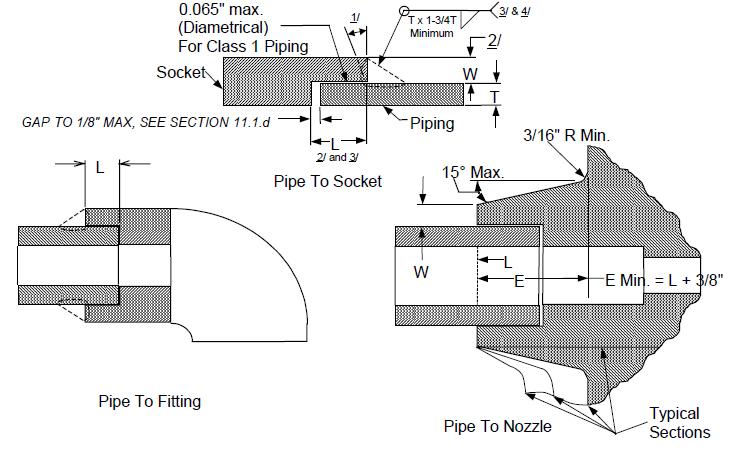
3. See C.5 for scribe line marking requirements.
4. Fittting may be reused with reduced socket depth (L) under the following conditions:
a. The pipe end gap clearance shall be held to 1/16” maximum.
b. The amount of socket depth (L) reduction permitted is based on nominal pipe size and diametrical clearance. Socket depth may not be reduced if diametrical clearance exceeds .065”.
Nominal Pipe Size
Minimum Socket Depth (L) for Re Weld with Maximum Diametrical Clearance of .025” and Less .026” .065” ½” and Less 3/8” 3/16” 9/32” ¾” thru 1 ½” 1/2” 1/4” 3/8” 2” 5/8” 5/16” 15/32”
Original Socket Depth
WI Q 3030
PIPE WELDING WORKMANSHIP & TRAINING GUIDE Process Owner QA
NIMS Page 96 of 115 Revision 4/7/2021
ENCLOSURE G Figure 12 P 15, Socket Flange, Fillet Welded ENCLOSURE G Figure 12 P 15, Socket Flange, Fillet Welded
NOTES:
1. Up through 22° bevel may be used.
2. Flange thickness and minimum socket depth (L) shall be IAW applicable specifications for the flange.
3. Seal weld required when used for salt water and other corrosive fluids, and base material is not resistant to crevice corrosion.
4. See C.5 for reference marking requirements.
5. Fittings (including SUBSAFE) may be reused with reduced socket depth (L) under the following conditions:
a. The pipe end gap clearance shall be held to 1/16" maximum.
b. If the diametrical clearance between the pipe and the fitting is 0.025" and less, the L dimension may be reduced by 50% of the specified dimension.
c. If the diametrical clearance is greater than 0.025", but is within 0.065", the L dimension may be reduced by 25% of the specified dimension. The provisions of reduced socket depth do not apply if the diametrical clearance exceeds 0.065".
Nominal Pipe Size
Minimum Socket Depth (L) for re weld with Maximum Diametrical Clearance of 0.025” and less 0.026” 0.065” ½” and Less 3/8” 3/16” 9/32” ¾” thru 1 ½” 1/2” 1/4” 3/8” 2” 5/8” 5/16” 15/32”
Original Socket Depth
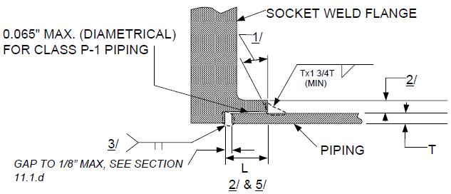
WI Q 3030
PIPE WELDING WORKMANSHIP & TRAINING GUIDE Process Owner QA
NIMS Page 97 of 115 Revision 4/7/2021
NIMS Page 98 of 115 Revision 4/7/2021
Process Owner QA
ENCLOSURE G Figure 13 P 80, Bell End Fitting, Socket Weld Joint ENCLOSURE G Figure 13 P 80, Bell End Fitting, Socket Weld Joint
NOTES:
NPS L
¼” to ¾” 25/64” 1” 29/64” 1 ¼” 1/2" 1 ½” to 2” 5/8” 2 ½” to 3” 13/16” 4” 57/64” 5” 1.0” 6” 1 1/16” 8” 1 5/16” 10” 1.5” 12” 1 5/8”
1. Minimum thickness (T) in all areas after expansion is equal to the nominal pipe wall thickness.

2. Minimum insertion depth (L) shall be in accordance above table requirements. Minimum insertion depth may be reduced to ¾ L if diametrical clearance is less than .025”.
3. Fillet weld leg (T) shall extend to the top of the expanded pipe/fitting.
PIPE WELDING WORKMANSHIP & TRAINING GUIDE
Q 3030
WI
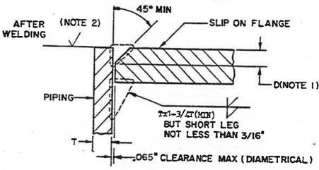


WI Q 3030
PIPE WELDING WORKMANSHIP & TRAINING GUIDE Process Owner QA
NIMS Page 99 of 115 Revision 4/7/2021
ENCLOSURE G Figure 14 P 16, Welded Slip on Flange, Fillet Reinforced ENCLOSURE G Figure 14 P 16, Welded Slip on Flange, Fillet Reinforced NOTES: 1. Dimension “D” to be as follows: Pipe Size (IPS) Dimension “D” 2” and below 3/16” 2 ½” through 7” 1/4” 8” through 16” 5/16” 2. Final machined surface shall have a maximum surface roughness of 125 RHR.
NIMS Page 100 of 115 Revision 4/7/2021
ENCLOSURE G Figure 15 P 17, Structural Sleeve For Piping Penetration
ENCLOSURE G Figure 15 P 17, Structural Sleeve For Piping Penetration
NOTES:
1. The design of the sleeve to be as specified on the applicable sleeve drawing.
2. Maximum diametrical clearance shall be as follows: Pipe Size (IPS)
Diametrical Clearance 1/4” through 3 ½” 1/16” 4” through 8” 1/8” Greater than 8” 3/16”
3. The applicable installation drawing shall be specify whether one or both ends of the sleeve shall be welded to the pipe.
4. When both ends of the sleeve are to be welded to the pipe, leave a small (approximately 1/2”) gap in root of one weld which shall serve as a vent to prevent pressure build up between pipe and sleeve. This vent shall be left open throughout welding both joints and closed and built up to required fillet size as the final portion of the weld.

WI Q 3030
PIPE WELDING WORKMANSHIP & TRAINING GUIDE Process Owner QA
NIMS Page 101 of 115 Revision 4/7/2021
ENCLOSURE G Figure 16 P 42, Double Fillet Welded Slip on Flange
ENCLOSURE G Figure 16 P 42, Double Fillet Welded Slip on Flange

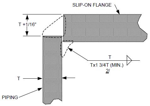
NOTES:
1. This joint shall not be used with butterfly valves, spiral wound gaskets, or flanged joints in oil systems.
2. T x 1 ¾ T minimum; however, the short leg shall not be less than 3/16”.
Q 3030
PIPE WELDING WORKMANSHIP & TRAINING GUIDE Process Owner QA WI
NIMS
PIPE WELDING WORKMANSHIP & TRAINING GUIDE Process Owner QA WI
ENCLOSURE G Figure 17 P 60, Branch Connection, Internal Fillet Welded
ENCLOSURE G Figure 17 P 60, Branch Connection, Internal Fillet Welded
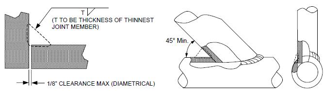
NOTES:
1. May be used for P 2 piping only.
2. Maximum pressure = 150 PSI, temperature = 449 °F.
Page 102 of 115 Revision 4/7/2021
Q 3030
NIMS Page 103 of 115 Revision 4/7/2021
PIPE WELDING WORKMANSHIP & TRAINING GUIDE Process Owner QA WI
ENCLOSURE G Figure 18 P 61, Branch Connection, External Fillet Welded ENCLOSURE G Figure 18 P 61, Branch Connection, External Fillet Welded
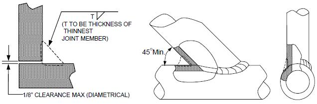
NOTES:
1. May be used for P 2 piping only.
2. Maximum pressure = 150PSI, temperature = 449°F.
Q 3030
NIMS Page 104 of 115 Revision 4/7/2021
ENCLOSURE G Figure 19 P 62, Branch Connection, Welded on One Side, External Fillet Reinforced
ENCLOSURE G Figure 19 P 62, Branch Connection, Welded on One Side, External Fillet-Reinforced

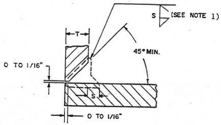

NOTES:
1. (S) shall be 1/2T or 3/16”, whichever is less. Where additional reinforcement is required, (S) shall be as specified by design.
2. May be used for P 2 piping only.
3. Maximum pressure = 150 PSI. Temperature = 449°F.
PIPE WELDING WORKMANSHIP & TRAINING GUIDE Process Owner QA WI Q 3030
NIMS Page 105 of 115 Revision 4/7/2021
ENCLOSURE G Figure 20 P 63, Branch Connection, Welded Both Sides, External Fillet Reinforced
ENCLOSURE G Figure 20 P 63, Branch Connection, Welded Both Sides, External Fillet Reinforced

NOTES:
1. (S) shall be 1/2T or 3/16” whichever is less. Where additional reinforcement is required, (S) shall be as specified by design.
2. May be used for P 2 piping only.
3. Maximum pressure = 150 PSI, temperature = 449°F.
4. (L) = Maximum distance from open pipe end.

Pipe IPS L Max Up to 12” ID of Pipe 12” to 24” 1 ½ times ID 24” and over Unlimited
PIPE WELDING WORKMANSHIP & TRAINING GUIDE
3030
Process Owner QA WI Q
NIMS Page 106 of 115 Revision 4/7/2021
ENCLOSURE G Figure 21 P 64, Branch Connection, Welded on Removable Backing Ring, External Fillet Reinforced


ENCLOSURE G Figure 21 P 64, Branch Connection, Welded on Removable Backing Ring, External Fillet-Reinforced
NOTES:
1. Root opening (Y) for use with backing rings: 3” IPS or less = 3/16”, over 3” IPS = 1/4” minimum
2. (S) shall be 1/2T or 3/16”, whichever is less. Where additional reinforcement is required, (S) shall be as specified by design.
3. May be used for P 2 piping only.
4. Maximum pressure = 150 PSI, temperature = 449°F.
3030
PIPE WELDING WORKMANSHIP & TRAINING GUIDE Process Owner QA WI Q
NIMS Page 107 of 115 Revision 4/7/2021
PIPE WELDING WORKMANSHIP & TRAINING GUIDE Process Owner QA
ENCLOSURE G Figure 22 P 66, Branch Connection, Welded on Removable Backing Ring, Internal Fillet Reinforced

ENCLOSURE G Figure 22 P 66, Branch Connection, Welded on Removable Backing Ring, Internal Fillet-Reinforced
NOTES:

1. Root openings (Y) for use with backing rings: Pipe sizes 3” or less, 3/16” minimum; Pipe sizes over 3”, 1/4” minimum.
2. (S) shall be 1/2T or 3/16”, whichever is less. Where additional reinforcement is required, (S) shall be as specified by design.

3030
WI Q
NIMS
ENCLOSURE G Figure 23 P 68, Internally Reinforced Fittings, Branch Connection, Welded on Both Sides, Single Bevel J 23
ENCLOSURE G Figure 23 P 68, Internally Reinforced Fittings, Branch Connection, Welded on Both Sides, Single Bevel J-23
NOTES:
1. Welding from one side only is permissible for class P 2 piping made from 70/30 or 90/10 CuNi in the following systems:
a. Fire Main/Salt Water, Chilled Water, AFFF, JP 5, Misc. Seawater Cooling Aux., Machinery Cooling Water, Potable Water, and Ships Service Air
b. Other materials/systems may not be welded from one side only without cognizant engineering department approval.
2. Welds not covered by Note 1 must be welded on both sides or welded from one side w ith full penetration.
3. Hole in the parent pipe should match the fittings inside diameter to within ±1/8".
4. Boss may be end prepped for socket weld, butt weld, or sil braze joint designs, however fit up and welding are the same.

5. The use of this joint design in class P 1 systems for joints 4 inches and smaller welded from one side only requires specific welding engineering approval/concurrence.
Page 108 of 115 Revision 4/7/2021
PIPE WELDING WORKMANSHIP & TRAINING GUIDE Process Owner QA WI Q 3030
NIMS
ENCLOSURE G Figure 24 P 70, Branch Connection with Pilot, Fillet Reinforced ENCLOSURE G Figure 24 P 70, Branch Connection with Pilot, Fillet Reinforced
NOTES:
1. Root opening (Y) shall conform to the following:
a. Pipe sizes 3” or less, 3/16”
b. Pipe sizes over 3”, 1/4” minimum.
2. For bosses designed as integrally reinforced branch fittings, size of fillet (S) shall be 1/2T or 3/16” whichever is less.
109 of 115 Revision 4/7/2021

3030
PIPE WELDING WORKMANSHIP & TRAINING GUIDE Process Owner QA WI Q
Page
NIMS
PIPE WELDING WORKMANSHIP & TRAINING GUIDE Process Owner QA
ENCLOSURE G Figure 25 P 71, Branch Connection With Plug, Fillet Reinforced ENCLOSURE G Figure 25 P 71, Branch Connection With Plug, Fillet Reinforced
NOTES:
1. Root opening (Y) shall conform to the following:
a. Pipe sizes 3” or less, 3/16”
b. Pipe sizes over 3”, 1/4” minimum.
2. For bosses designed as integrally reinforced branch fittings, size of fillet (S) shall be 1/2T or 3/16” whichever is less.

3030
WI Q
Page 110 of 115 Revision 4/7/2021
ENCLOSURE G Figure 26 P 72, Branch Connection without Pilot, Fillet Reinforced ENCLOSURE G Figure 26 P 72, Branch Connection without Pilot, Fillet Reinforced


NOTES:
1. Root opening (Y) shall conform to the following:
a. Pipe sizes 3” or less, 3/16”
b. Pipe sizes over 3”, 1/4” minimum.
2. For bosses designed as integrally reinforced branch fittings, size of fillet (S) shall be 1/2T or 3/16” whichever is less.
3. Diameter of the attachment (D) shall be 3/16” less than the final bore for 1” IPS and smaller branch pipe: 1/4” less than final bore for branch pipe over 1” IPS.
Q 3030
PIPE WELDING WORKMANSHIP & TRAINING GUIDE Process Owner QA WI
NIMS Page 111 of 115 Revision 4/7/2021
NIMS
ENCLOSURE G Figure 27 P 73 and P 74, Joint Design and Fit up Dimensions, Consumable Insert Butt Joints
ENCLOSURE G Figure 27 P 73 and P 74, Joint Design and Fit up Dimensions, Consumable Insert Butt Joints
Joint Number
Dim (B) 1” & Below Notes 4 & 9
Dim (B) Above 1” Note 4 Dim (C) Clearance Dim (D) Diff in Dia. Note 5 & 6
P 73 .010” ± .005” .030” ± .005” .031” max .031” max 40⁰± 5⁰ P 74 .010” ± .005” .030” ± .005” .031” max .031” max 25⁰± 5⁰
NOTES:
1. Consumable insert shall conform to the requirements of MIL I 23413, Class 1.
2. The depth of counterbore (A) may be obtained by machining, expanding, or forming and shall be 3/8” or T whichever is greater, except that on elbows, (A) shall be limited to a depth which will not reduce the wall thickness below the minimum allowable value. In no case shall (A) be less than 1/8”.
3. Center of the radius shall be located so that the plane of the root face will extend not more than .015” from the nominal positions shown. (See insert sketch for joint type P 74).
4. For joints of nickel copper (S 42) and inconel (S 43) materials dimensions (B) may be changed to 1/16” +/ 1/64” for joint P 74.
5. For joints of nickel copper (S 42) and inconel (S 43) materials dimensions Ө may be changed to 47 1/2⁰ ± 2 1/2⁰ for joint P 73.
6. For joints of copper nickel (S 34) in seawater systems material dimensions Ө may be changed to 45⁰ ± 5⁰ for joint P 73.
7. Machining of the mating pipe and fitting ends to improve fit up is permitted provided the wall thickness is maintained above the minimum allowable dimensions.
8. Jigs and/or fixtures shall be used as necessary to establish and maintain joint alignment and fit up

9. Actual measurement of the minimum land thickness is not necessary. Visual inspection shall be made to assure that beveled edges have been removed.

10. An alternate method for assembling and tacking the insert joint, on pipe sizes 4” and greater, is to fit the insert ring on one end of the joint. Preform the ring by mechanical means, with approximately 1” of excess length, and hand fit. Tack the insert to the joint preparation with tack welds, approximately 1/8” long, spaced approximately ½” apart, using a purge cup to provide argon gas purge in way of the tack weld area. Deposit tack welds progressively around the ring to the half way point. Hand fit the last half of the insert by cutting off excess with hack saw and filing end of ring to make the ends fit metal to metal or within .020” maximum tolerance. Continue tacking as before, closing the ends of the ring last. The mating pipe is fit up both pipe joint preparations and the inserts are tack welded together.
Page 112 of 115 Revision 4/7/2021
PIPE WELDING WORKMANSHIP & TRAINING GUIDE Process Owner QA WI Q 3030
ENCLOSURE G Figure 28 Modified P 73 and Modified P 74, Open Root Butt Joint Design and Fit up Dimensions
ENCLOSURE G Figure 28 Modified P 73 and Modified P 74, Open Root Butt Joint Design and Fit-up Dimensions
NOTES:
1. The depth of counterbore (A) may be obtained by machining, expanding, or forming and shall be 3/8” or T whichever is greater, except that on elbows, (A) shall be limited to a depth which will not reduce the wall thickness below the minimum allowable value. In no case shall (A) be less than 1/8”.


2. Machining of the mating pipe and fitting ends to improve fit up is permitted provided the wall thickness is maintained above the minimum allowable dimensions.
3. Jigs and/or fixtures shall be used as necessary to establish and maintain joint alignment and fit up.
Q 3030
PIPE WELDING WORKMANSHIP & TRAINING GUIDE Process Owner QA WI
NIMS Page 113 of 115 Revision 4/7/2021
ENCLOSURE G Figure 29 Transition Joints Between CRES and NiCu or CuNi ENCLOSURE G Figure 29 Transition Joints Between CRES and NiCu or CuNi

NOTES:
1. Use applicable welding technique sheet of based on materials being jointed.
2. Root opening must be wide enough for minimum of two passes per layer.
3. Butter with sufficient material to assure a minimum thickness of 1/8” remains after preparation for final joint assembly.
4. Following final joint preparation for fit up/assembly, buttering shall be liquid penetrant inspected if required for the class of welding being performed. Where liquid penetrant inspection of the completed weld joint is required, all exposed surfaces of the buttered area shall also be LPT i nspected during the inspection of the finished weld joint. If radiographic inspection is required for the completed joint, the buttered edges shall also require radiographic inspection. The buttered area and the completed weld may be radiographed at the same time.
5. For weld deposited buttering that forms part of a pressure boundary subject to submergence pressure, UT inspection shall also be performed for defects and lack of bond prior to joint welding.
6. When joint documentation is required, two weld joint history records are required, one for buttering and one for the final weld joint.
114 of 115
4/7/2021
WI Q 3030
Page
PIPE WELDING WORKMANSHIP & TRAINING GUIDE Process Owner QA
NIMS
Revision

