1 minute read
ENCLOSURE G – Figure 7 – P-6, Butt Joint, Permanent Backing Ring, U-Groove


NIMS PIPE WELDING WORKMANSHIP & TRAINING GUIDE
Process Owner – QA
Advertisement
WI-Q-3030
ENCLOSURE G – Figure 7 – P-6, Butt Joint, Permanent Backing Ring, U-Groove ENCLOSURE G – Figure 7 – P-6, Butt Joint, Permanent Backing Ring, U-Groove
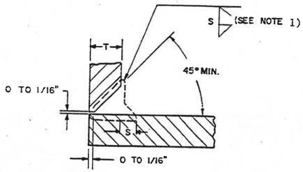
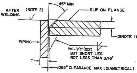
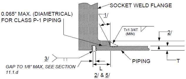
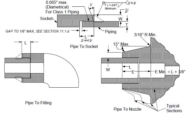
NOTES: 1. Backing ring to be IAW Figure 1, (Straight ring only). 2. Maximum diametrical clearance between ID of pipe and OD of backing ring shall be as follows: Pipe Class Size Clearance P-1 & P-LT All .030” P-2 2” IPS and Smaller .045” P-3 2 ½” IPS and Larger .065” 3. Backing rings may be tack welded inside or outside. 4. The depth of counterbore, “A” shall be ½” minimum or T minimum, whichever is larger to ensure proper pipe inside diameter. Counterbore for elbows shall be limited to a depth which will not reduce wall thickness below the design minimum. 5. Machining or expanding of mating pipe and fitting ends to improve fit-up is permitted, provided the wall thickness is not reduced below design minimum. 6. Jigs and fixtures shall be used as necessary to establish and maintain joint alignment and fit-up.
Page 92 of 115 Revision 4/7/2021