1 minute read
ENCLOSURE G – Figure 15 – P-17, Structural Sleeve For Piping Penetration

NIMS PIPE WELDING WORKMANSHIP & TRAINING GUIDE
Process Owner – QA
Advertisement
WI-Q-3030
ENCLOSURE G – Figure 15 – P-17, Structural Sleeve For Piping Penetration ENCLOSURE G – Figure 15 – P-17, Structural Sleeve For Piping Penetration
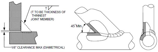
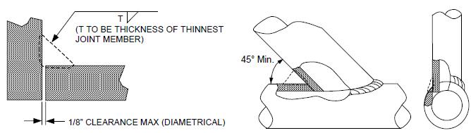
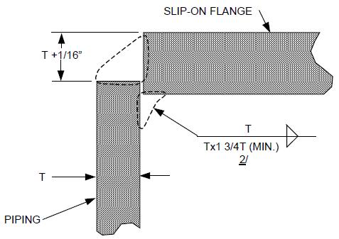
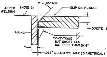
NOTES: 1. The design of the sleeve to be as specified on the applicable sleeve drawing. 2. Maximum diametrical clearance shall be as follows: Pipe Size (IPS) Diametrical Clearance 1/4” through 3 ½” 4” through 8” 1/16” 1/8” Greater than 8” 3/16” 3. The applicable installation drawing shall be specify whether one or both ends of the sleeve shall be welded to the pipe. 4. When both ends of the sleeve are to be welded to the pipe, leave a small (approximately 1/2”) gap in root of one weld which shall serve as a vent to prevent pressure build up between pipe and sleeve. This vent shall be left open throughout welding both joints and closed and built up to required fillet size as the final portion of the weld.
Page 100 of 115 Revision 4/7/2021