9 minute read
ENCLOSURE G – Figure 20 – P-63, Branch Connection, Welded Both Sides, External Fillet Reinforced

NIMS PIPE WELDING WORKMANSHIP & TRAINING GUIDE
Process Owner – QA
Advertisement
WI-Q-3030
ENCLOSURE G – Figure 20 – P-63, Branch Connection, Welded Both Sides, External Fillet Reinforced ENCLOSURE G – Figure 20 – P-63, Branch Connection, Welded Both Sides, External Fillet Reinforced

NOTES: 1. (S) shall be 1/2T or 3/16” whichever is less. Where additional reinforcement is required, (S) shall be as specified by design. 2. May be used for P-2 piping only. 3. Maximum pressure = 150 PSI, temperature = 449°F. 4. (L) = Maximum distance from open pipe end. Pipe IPS L Max Up to 12” ID of Pipe 12” to 24” 1 ½ times ID 24” and over Unlimited
Page 105 of 115 Revision 4/7/2021
NIMS PIPE WELDING WORKMANSHIP & TRAINING GUIDE
Process Owner – QA
WI-Q-3030
ENCLOSURE G – Figure 21 – P-64, Branch Connection, Welded on Removable Backing Ring, External Fillet-Reinforced ENCLOSURE G – Figure 21 – P-64, Branch Connection, Welded on Removable Backing Ring, External Fillet-Reinforced


NOTES: 1. Root opening (Y) for use with backing rings: 3” IPS or less = 3/16”, over 3” IPS = 1/4” minimum 2. (S) shall be 1/2T or 3/16”, whichever is less. Where additional reinforcement is required, (S) shall be as specified by design. 3. May be used for P-2 piping only. 4. Maximum pressure = 150 PSI, temperature = 449°F.
Page 106 of 115 Revision 4/7/2021
NIMS PIPE WELDING WORKMANSHIP & TRAINING GUIDE
Process Owner – QA
WI-Q-3030
ENCLOSURE G – Figure 22 – P-66, Branch Connection, Welded on Removable Backing Ring, Internal Fillet-Reinforced ENCLOSURE G – Figure 22 – P-66, Branch Connection, Welded on Removable Backing Ring, Internal Fillet-Reinforced

NOTES: 1. Root openings (Y) for use with backing rings: Pipe sizes 3” or less, 3/16” minimum; Pipe sizes over 3”, 1/4” minimum. 2. (S) shall be 1/2T or 3/16”, whichever is less. Where additional reinforcement is required, (S) shall be as specified by design.
Page 107 of 115 Revision 4/7/2021
NIMS PIPE WELDING WORKMANSHIP & TRAINING GUIDE
Process Owner – QA
WI-Q-3030
ENCLOSURE G – Figure 23 – P-68, Internally Reinforced Fittings, Branch Connection, Welded on Both Sides, Single Bevel J-23 ENCLOSURE G – Figure 23 – P-68, Internally Reinforced Fittings, Branch Connection, Welded on Both Sides, Single Bevel J-23

NOTES: 1. Welding from one side only is permissible for class P-2 piping made from 70/30 or 90/10 CuNi in the following systems: a. Fire Main/Salt Water, Chilled Water, AFFF, JP-5, Misc. Seawater Cooling Aux., Machinery Cooling Water, Potable Water, and Ships Service Air b. Other materials/systems may not be welded from one side only without cognizant engineering department approval. 2. Welds not covered by Note 1 must be welded on both sides or welded from one side with full penetration. 3. Hole in the parent pipe should match the fittings inside diameter to within ±1/8". 4. Boss may be end-prepped for socket weld, butt weld, or sil-braze joint designs, however fit-up and welding are the same. 5. The use of this joint design in class P-1 systems for joints 4 inches and smaller welded from one side only requires specific welding engineering approval/concurrence.
Page 108 of 115 Revision 4/7/2021
NIMS PIPE WELDING WORKMANSHIP & TRAINING GUIDE
Process Owner – QA
WI-Q-3030
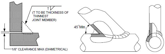
ENCLOSURE G – Figure 24 – P-70, Branch Connection with Pilot, Fillet-Reinforced ENCLOSURE G – Figure 24 – P-70, Branch Connection with Pilot, Fillet-Reinforced

NOTES: 1. Root opening (Y) shall conform to the following: a. Pipe sizes 3” or less, 3/16” b. Pipe sizes over 3”, 1/4” minimum. 2. For bosses designed as integrally reinforced branch fittings, size of fillet (S) shall be 1/2T or 3/16” whichever is less.
Page 109 of 115 Revision 4/7/2021
NIMS PIPE WELDING WORKMANSHIP & TRAINING GUIDE
Process Owner – QA
WI-Q-3030
ENCLOSURE G – Figure 25 – P-71, Branch Connection With Plug, Fillet-Reinforced ENCLOSURE G – Figure 25 – P-71, Branch Connection With Plug, Fillet-Reinforced

NOTES: 1. Root opening (Y) shall conform to the following: a. Pipe sizes 3” or less, 3/16” b. Pipe sizes over 3”, 1/4” minimum. 2. For bosses designed as integrally reinforced branch fittings, size of fillet (S) shall be 1/2T or 3/16” whichever is less.
Page 110 of 115 Revision 4/7/2021
NIMS PIPE WELDING WORKMANSHIP & TRAINING GUIDE
Process Owner – QA
WI-Q-3030
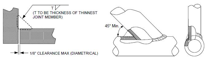
ENCLOSURE G – Figure 26 – P-72, Branch Connection without Pilot, Fillet-Reinforced ENCLOSURE G – Figure 26 – P-72, Branch Connection without Pilot, Fillet-Reinforced


NOTES: 1. Root opening (Y) shall conform to the following: a. Pipe sizes 3” or less, 3/16” b. Pipe sizes over 3”, 1/4” minimum. 2. For bosses designed as integrally reinforced branch fittings, size of fillet (S) shall be 1/2T or 3/16” whichever is less. 3. Diameter of the attachment (D) shall be 3/16” less than the final bore for 1” IPS and smaller branch pipe: 1/4” less than final bore for branch pipe over 1” IPS.
Page 111 of 115 Revision 4/7/2021
NIMS PIPE WELDING WORKMANSHIP & TRAINING GUIDE
Process Owner – QA
WI-Q-3030
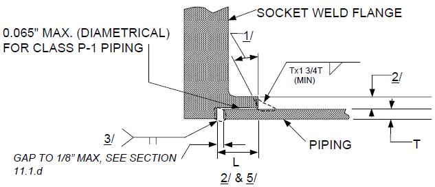
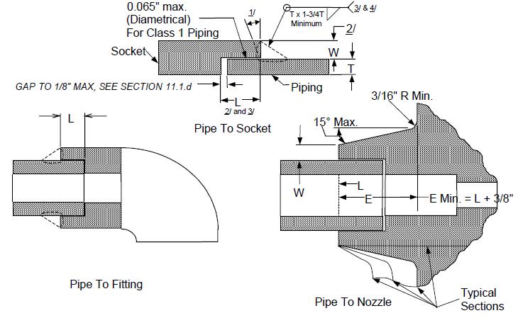
ENCLOSURE G – Figure 27 – P-73 and P-74, Joint Design and Fit-up Dimensions, Consumable Insert Butt Joints ENCLOSURE G – Figure 27 – P-73 and P-74, Joint Design and Fit-up Dimensions, Consumable Insert Butt Joints


Joint Number Dim (B) 1” & Below Notes 4 & 9 Dim (B) Above 1” Note 4 Dim (C) Clearance
Dim (D) Diff in Dia. Note 5 & 6 P-73 .010” ± .005” .030” ± .005” .031” max .031” max 40⁰± 5⁰ P-74 .010” ± .005” .030” ± .005” .031” max .031” max 25⁰± 5⁰
NOTES: 1. Consumable insert shall conform to the requirements of MIL-I-23413, Class 1. 2. The depth of counterbore (A) may be obtained by machining, expanding, or forming and shall be 3/8” or T whichever is greater, except that on elbows, (A) shall be limited to a depth which will not reduce the wall thickness below the minimum allowable value. In no case shall (A) be less than 1/8”. 3. Center of the radius shall be located so that the plane of the root face will extend not more than .015” from the nominal positions shown. (See insert sketch for joint type P-74). 4. For joints of nickel-copper (S-42) and inconel (S-43) materials dimensions (B) may be changed to 1/16” +/- 1/64” for joint P-74. 5. For joints of nickel-copper (S-42) and inconel (S-43) materials dimensions Ө may be changed to 47-1/2⁰ ± 2-1/2⁰ for joint P-73. 6. For joints of copper-nickel (S-34) in seawater systems material dimensions Ө may be changed to 45⁰ ± 5⁰ for joint P-73. 7. Machining of the mating pipe and fitting ends to improve fit-up is permitted provided the wall thickness is maintained above the minimum allowable dimensions. 8. Jigs and/or fixtures shall be used as necessary to establish and maintain joint alignment and fit-up. 9. Actual measurement of the minimum land thickness is not necessary. Visual inspection shall be made to assure that beveled edges have been removed. 10. An alternate method for assembling and tacking the insert joint, on pipe sizes 4” and greater, is to fit the insert ring on one end of the joint. Preform the ring by mechanical means, with approximately 1” of excess length, and hand fit. Tack the insert to the joint preparation with tack welds, approximately 1/8” long, spaced approximately ½” apart, using a purge cup to provide argon gas purge in way of the tack weld area. Deposit tack welds progressively around the ring to the half-way point. Hand fit the last half of the insert by cutting off excess with hack saw and filing end of ring to make the ends fit metal to metal or within .020” maximum tolerance. Continue tacking as before, closing the ends of the ring last. The mating pipe is fit-up both pipe joint preparations and the inserts are tack welded together.
Page 112 of 115 Revision 4/7/2021
NIMS PIPE WELDING WORKMANSHIP & TRAINING GUIDE
Process Owner – QA
WI-Q-3030
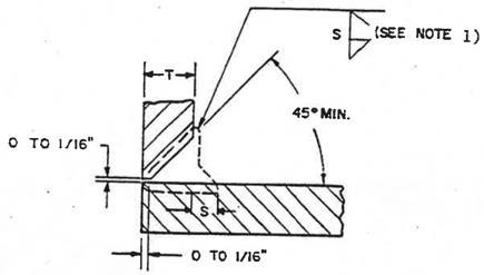
ENCLOSURE G – Figure 28 – Modified P-73 and Modified P-74, Open Root Butt Joint Design and Fit-up Dimensions ENCLOSURE G – Figure 28 – Modified P-73 and Modified P-74, Open Root Butt Joint Design and Fit-up Dimensions


NOTES: 1. The depth of counterbore (A) may be obtained by machining, expanding, or forming and shall be 3/8” or T whichever is greater, except that on elbows, (A) shall be limited to a depth which will not reduce the wall thickness below the minimum allowable value. In no case shall (A) be less than 1/8”. 2. Machining of the mating pipe and fitting ends to improve fit-up is permitted provided the wall thickness is maintained above the minimum allowable dimensions. 3. Jigs and/or fixtures shall be used as necessary to establish and maintain joint alignment and fit-up.
Page 113 of 115 Revision 4/7/2021
NIMS PIPE WELDING WORKMANSHIP & TRAINING GUIDE
Process Owner – QA
WI-Q-3030
ENCLOSURE G – Figure 29 – Transition Joints Between CRES and NiCu or CuNi ENCLOSURE G – Figure 29 – Transition Joints Between CRES and NiCu or CuNi

NOTES: 1. Use applicable welding technique sheet of based on materials being jointed. 2. Root opening must be wide enough for minimum of two passes per layer. 3. Butter with sufficient material to assure a minimum thickness of 1/8” remains after preparation for final joint assembly. 4. Following final joint preparation for fit up/assembly, buttering shall be liquid penetrant inspected if required for the class of welding being performed. Where liquid penetrant inspection of the completed weld joint is required, all exposed surfaces of the buttered area shall also be LPT inspected during the inspection of the finished weld joint. If radiographic inspection is required for the completed joint, the buttered edges shall also require radiographic inspection. The buttered area and the completed weld may be radiographed at the same time. 5. For weld deposited buttering that forms part of a pressure boundary subject to submergence pressure, UT inspection shall also be performed for defects and lack of bond prior to joint welding. 6. When joint documentation is required, two weld joint history records are required, one for buttering and one for the final weld joint.
Page 114 of 115 Revision 4/7/2021