8 minute read
ENCLOSURE B.3 – Welder Workmanship – Completed Weld


NIMS PIPE WELDING WORKMANSHIP & TRAINING GUIDE
Process Owner – QA
Advertisement
WI-Q-3030
ENCLOSURE B.3 – Welder Workmanship – Completed Weld ENCLOSURE B.3 – Welder Workmanship – Completed Weld
Welder Workmanship – This section contains all of the information a welder needs to verify the weld has been made to requirements of the technical publication.
Area of Inspection – Surfaces to be covered by weld and adjacent base metal surfaces within ½" of expected toes of the weld.
Attribute ENCLOSURE B.3 – Welder Workmanship Acceptance Criteria – Completed Weld a Arc Strikes Unacceptable. For repair refer to Enclosure C.1. of arc strike removal sites in base material, b Burn Through Unacceptable.
c Cracks
Unacceptable. Authorization for Repair. Contact Welding Engineering prior to repair of cracks. d Crater Pits Acceptable, provided no cracks, acceptable root concavity/convexity, min weld thickness requirements are met, and bottom is visible. e Fusion Incomplete Unacceptable.
f Incomplete Penetration
g Overlap Unacceptable This condition is not normally visible except when the weld has been cut exposing the cross section of the root layer.
Authorization for repair – Contact Welding Engineering when this condition is found.

Page 34 of 115 Revision 4/7/2021
NIMS PIPE WELDING WORKMANSHIP & TRAINING GUIDE
Process Owner – QA
WI-Q-3030
Attribute ENCLOSURE B.3 – Welder Workmanship Acceptance Criteria – Completed Weld
i Sharp Irregularities

j Slag Class 1: Unacceptable. Class 2 and 3: Tightly adherent slag that cannot be removed by a slag pick or wire brush is permissible for VT. Slag shall not interfere with evaluation of other visual attributes or other NDT. If MT, RT, or UT is required, then slag 1/8" or less in diameter or length is allowed. If PT is required, then no slag is permitted. Butt Weld Reinforcement – Butt weld surfaces shall not be below adjacent base metal surface, except for weld toes that do not exceed allowed undercut limits. Reinforcement shall not exceed the following limits: Class Thickness Max Reinforcement
k Butt Weld Reinforcement Class 1: (A-1, A-2, AF, A-LT, P-1, P-LT, T-1, T-2) 0 to ¼" Greater than ¼" up to 1" Greater than 1" up to 2" 1/16"
3/32"
1/8"
l Cleanliness (Including prep for NDT)
m CornerMelt Greater than 2" 5/32"
Class 2 & 3: (A-3, A4, M-1, M-2, P-2)
0 to ½" 3/32" Greater than ½" 5/32" To facilitate inspection, the weld and base material adjacent to the weld shall be free of paint, grease, dirt, and other foreign material. The area to be cleaned shall be as follows: For VT, the inspection area is the weld face and ½" adjacent base material. For MT (yoke), PT or RT, the area to be cleaned is the weld face and 1" of adjacent base material. For PT, the surface SHALL NOT be prepared by power wire brush, peening, tumbling, or shot, sand, grit or vapor blasting. For MT (prod), the area to be cleaned is the weld face and 3" of adjacent base material. For UT the area to be cleaned will be specified by the NDT Level III. Class 1: (A-1, A-2, A-F, A-LT, P1, P-LT, T-1,T-2) All thicknesses Class 2 & 3: (A-3, A-4, M-1, M-2, P-2) 1/64" or 10% of adjacent base material thickness (whichever is less) max. depth. As Welded: 1/16" max. depth After Grinding: 3/32" max. depth
Page 35 of 115 Revision 4/7/2021
NIMS PIPE WELDING WORKMANSHIP & TRAINING GUIDE
Process Owner – QA
WI-Q-3030
Attribute ENCLOSURE B.3 – Welder Workmanship Acceptance Criteria – Completed Weld All thicknesses

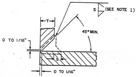
n Edge Melt (Sockets) Acceptable provided the weld size reference line is visible and weld size is sat.
o End Melt Class 1: (A-1, A-2, A-F, A-LT, P1, P-LT, T-1,T-2) All thicknesses Class 2 & 3: (A-3, A-4, M-1, M-2, P-2) ¼" and less thickness (greater than ¼" thickness undercut limits apply) 1/64" or 10% of adjacent base material thickness (whichever is less) max. depth
As Welded: 1/16" max. depth After Grinding: 3/32" max. depth
p Fillet & Socket Weld Size
q MeltThrough
r Arc Strike Removal Sites, Nicks, Gouges, Fabrication Scars, Grind Marks, & Surface Roughness Fillet Welds (Other Than Pipe): Minimum weld size shall not be less than specified by the WORK ITEM or Drawing. Weld size greater than required is acceptable provided all other requirements are met.
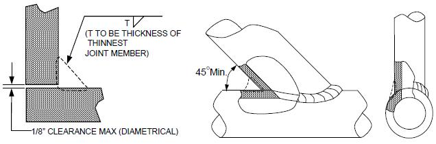
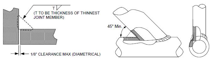
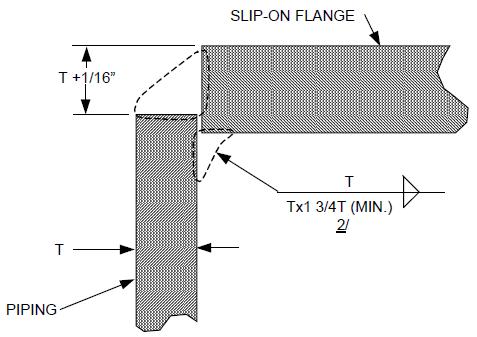
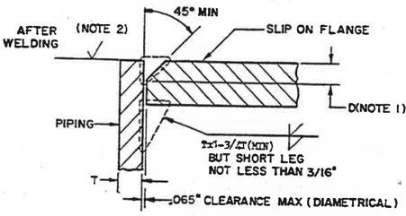
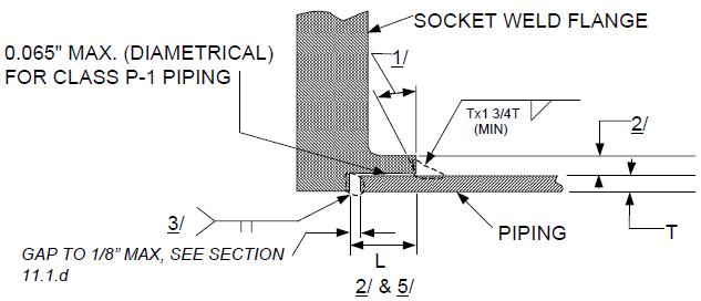
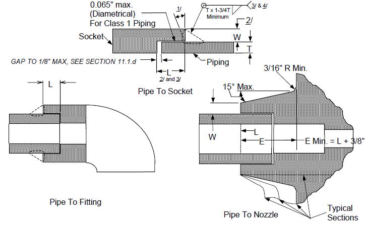
Sockets Welds:
Minimum leg length shall be “T” by “1-3/4T”, where “T” is the
Nominal Wall Thickness for the thinner member.
Throat Thickness: Socket welds with essentially flat contour are considered to have adequate throat thickness, provided the minimum specified leg length is met. Acceptable provided the areas do not contain cracks, crevices, unacceptable oxidation, or globules and root contour (e.g., concavity/convexity) limits are not exceeded. Class 1: (A-1, A-2, A-F, A-LT, P-1, P-LT, T-1,T-2) All thicknesses 1/64" or 10% of adjacent base material thickness (whichever is less). See Note Class 2 & 3: (A-3, A-4, M-1, M-2, P-2) Materials Less than ½" thick: 1/32" MAX depth. See Note Materials ½" and thicker: 1/16" MAX depth. See Note
Page 36 of 115 Revision 4/7/2021
NIMS PIPE WELDING WORKMANSHIP & TRAINING GUIDE
Process Owner – QA
WI-Q-3030
Attribute ENCLOSURE B.3 – Welder Workmanship Acceptance Criteria – Completed Weld
s OffsetPipe, MisalignmentOther than Pipe Note: The above are acceptable only if all the below are met: Minimum thickness requirements are met Bottom of depression is visible and rounded or free of notches The length of the discontinuity is 12" maximum (for pipe, pressure vessels, A-1, A-2, A-3, A-4, A-F, A-LT, P-1 and P-2, the length limit is 12" or 25% of the circumference, whichever is less)
Base Metal Thickness (Nominal thickness of thinner member) Maximum Offset (Misalignment) ¼" and less 25% of joint thickness Greater than ¼" to ¾" 25% of joint thickness, but not to exceed 1/8" MAX Greater than ¾" to 1-1/2" 3/16” MAX Greater than 1-1/2" 12-1/2% of joint thickness, but not to exceed ¼" MAX
t Porosity
“Wormhole” porosity is always unacceptable. Individual pores shall not exceed 3/32" in diameter or length. The sum of pore diameters or lengths shall not exceed 1/8" in any 2" length of weld. Do not count pores 1/32" or less in diameter or length. u Root Contour The contour of the root shall have a uniform radius and shall blend smoothly into the base material. Pipe less than 2" diameter and other shapes less than 5/32" thick 1/32" MAX*
Concavity Pipe 2" diameter and greater and other shapes 5/32" and greater in thickness 1/16" MAX*
*No concavity is allowed unless the resulting weld metal thickness meets the minimum wall thickness requirements of the adjacent base metal.
Pipe less than 2" diameter and other shapes less than 5/32" thick 1/16" MAX. For Cuni and NiCu consumable inserts, convexity up to 3/32" is acceptable provided the total length does not exceed 1".
Convexity Pipe 2" diameter and greater and other shapes 5/32" and greater in thickness
Centerline Crease Unacceptable. Ridged (Razorback) Root Unacceptable. 3/32" MAX. For Cuni and NiCu consumable inserts, convexity up to 1/8" is acceptable provided the total length does not exceed 25% of the inside circumference of the pipe.
Page 37 of 115 Revision 4/7/2021
NIMS PIPE WELDING WORKMANSHIP & TRAINING GUIDE
Process Owner – QA
WI-Q-3030
Attribute ENCLOSURE B.3 – Welder Workmanship Acceptance Criteria – Completed Weld
v Weld Spatter Class 1: Welds and adjacent base metal shall be free of spatter. Class 2 & 3: Any spatter that can be removed by hand wire brush is unacceptable. Tightly adherent spatter 1/8" or less in diameter or length is acceptable if VT or VT and MT are the only NDT required (and it does not interfere with NDT). However, spatter is also unacceptable for the following: 1) If other NDT (PT, RT, UT) is required; 2) On internal surfaces of closed systems, and 3) On surfaces which will be wetted. Note: Weld Spatter is unacceptable for piping welds. Class 1: (A-1, A-2, A-F, A-LT, P1, P-LT, T-1,T-2) All thicknesses 1/64" or 10% of minimum base material thickness (whichever is less) max. depth.
w Undercut
(See Note Below) Class 2 & 3: (A-3, A-4, M1, M-2, P-2) Thicknesses less than ½"
Class 2 & 3: (A-3, A-4, M-1, M-2, P-2) Thicknesses ½" and greater 1/32" or 10% of minimum base material thickness (whichever is less) max. depth. 1/16" max. depth; undercut exceeding 1/32" in depth shall not exceed 15% of the joint or 12" in any 36" length of weld, whichever is less.
x Seal Off & Wrap Around Welding y Angular Misalignment (Pipe) See Next Section
General guidance for Angular misalignment should not exceed 5o or as specified in manufactures drawings or written requirements.
ENCLOSURE B.3 – Welder Workmanship – Completed Weld

NOTE: Measured from unground adjacent base metal. In addition to the limits stated here, undercut SHALL NOT reduce wall thickness below minimum allowed. After grinding, undercut is acceptable provided minimum wall thickness is not violated. Seal Off And Wrap Around Welding
Page 38 of 115 Revision 4/7/2021
NIMS PIPE WELDING WORKMANSHIP & TRAINING GUIDE
Process Owner – QA
WI-Q-3030
ENCLOSURE B.3 – Welder Workmanship – Completed Weld

Acceptance Criteria – Fillet and fillet reinforced partial penetration welds shall be sealed off with weld at the end(s) of members (flat bars, angles, channels and tees) being joined to form a closed loop where surfaces are to be wetted. Members, which will not be wetted, shall be sealed off when practical. When specified by a weld all-around symbol, the minimum weld reinforcement shall be maintained (wrap around) at the end(s) of the attached members, except as noted below. When the member is located per tolerances and the full size fillet (wraparound) is not obtainable, the maximum size obtainable shall be considered acceptable provided the above seal-off requirement in the wetted areas is maintained.
Page 39 of 115 Revision 4/7/2021