report.
1:1 creative material practice.
page. introduction.
page 3 01 02 03 04 05 materiality process work.
page 4
06 research.
page 5-6 artifact making 1:1 process.
page 7-8 final artifact 1:1.
page 9 reflection. page 10
07 blibliography & list of figures.
page 11
The idea behind the project is to test materials that have been allocated for each group, and the material that I get is timber sheet and frame elements. The design behind my project is to make a timber frame that can rotate depending on the direction of the wind. The construction of the model will be built in a shoe box size in 1:1 scale and using material gathered from the workshop and scraps for testing the finishes that I will be implementing to my project. The main material that I use for the project is an old pine wood beams that will be reused for this project.
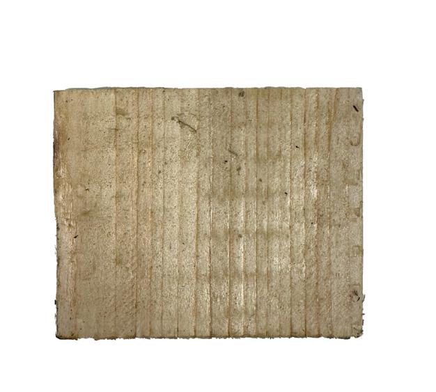
01 timber sheets and frame elements material that are allocated.
02 03 04 05 frames material type. 38mm x 300mm x 300mm material dimesions overall (WxHxL)
material surface.
WIND IN NORTHSHIELD
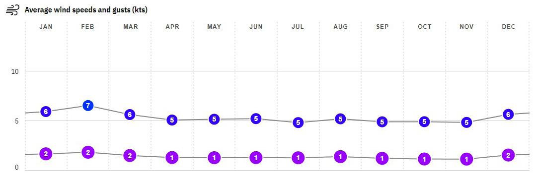
The research is derived from a website called "windfinder" and based on the observation taken between 2011 - 2024 came from both the southwest and north-east direction with the average wind speed of 7 knots.1

ENVIROMENTAL IMPACT AND SUSTAINABILITY.
Using timber as the main construction material can have its own benefit and disadvantages. The benefit of using timber is that it stores carbon in a building, which potentially reduce carbon footprints of a building. On the other hand, the most noticable concerns when dealing with timber is deforestation, which can cause a change in its enviromental impact and ecological balance.2
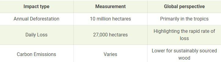
4 : enviromental impact table.
WIND FLOW EXPERIMENT
ON ARTIFACT 1:1
To test how wind interact wind the rotating panel I use a hairdryer in the lowest settings (10m/s), which turns into 5.14 knots.
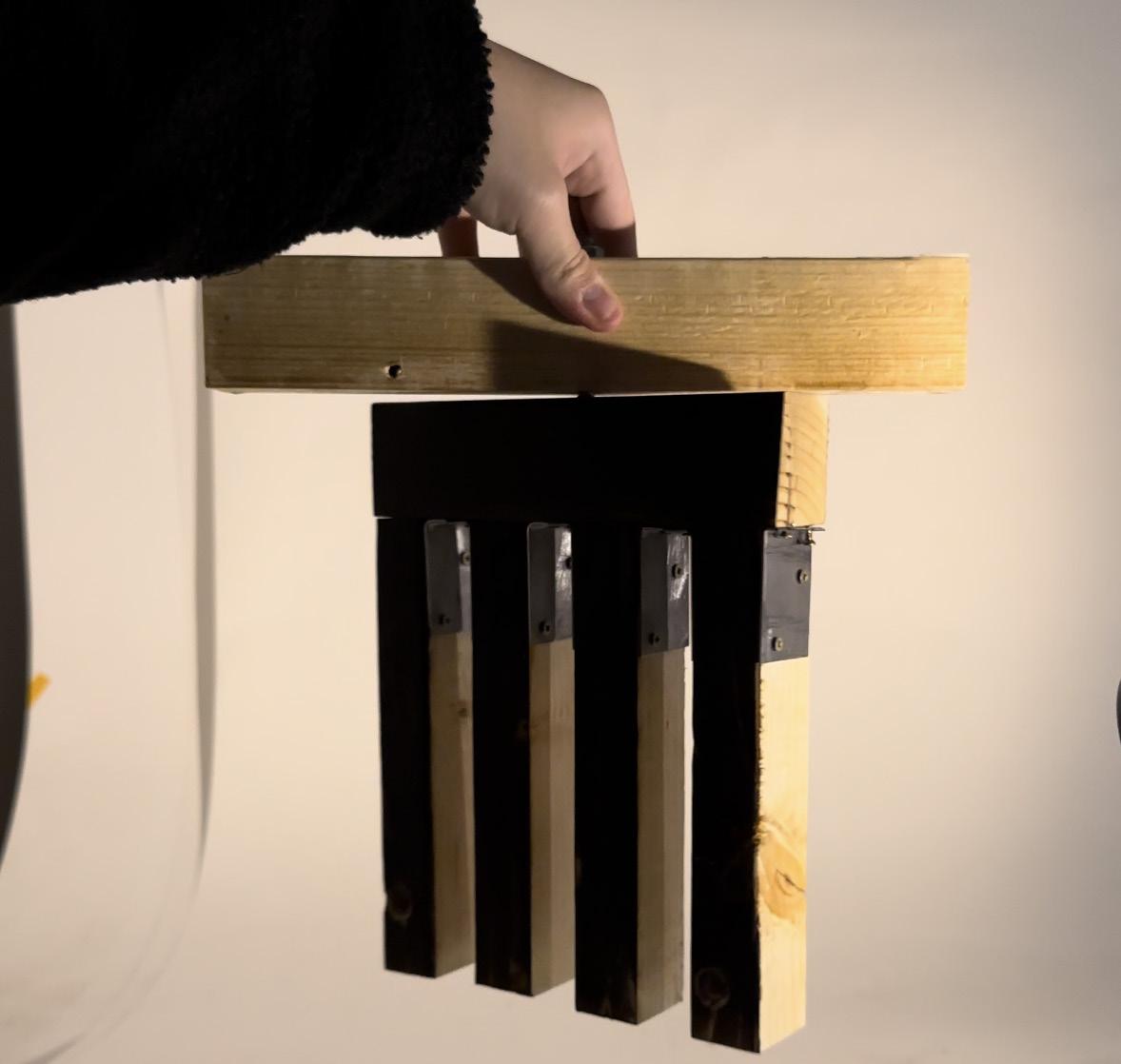
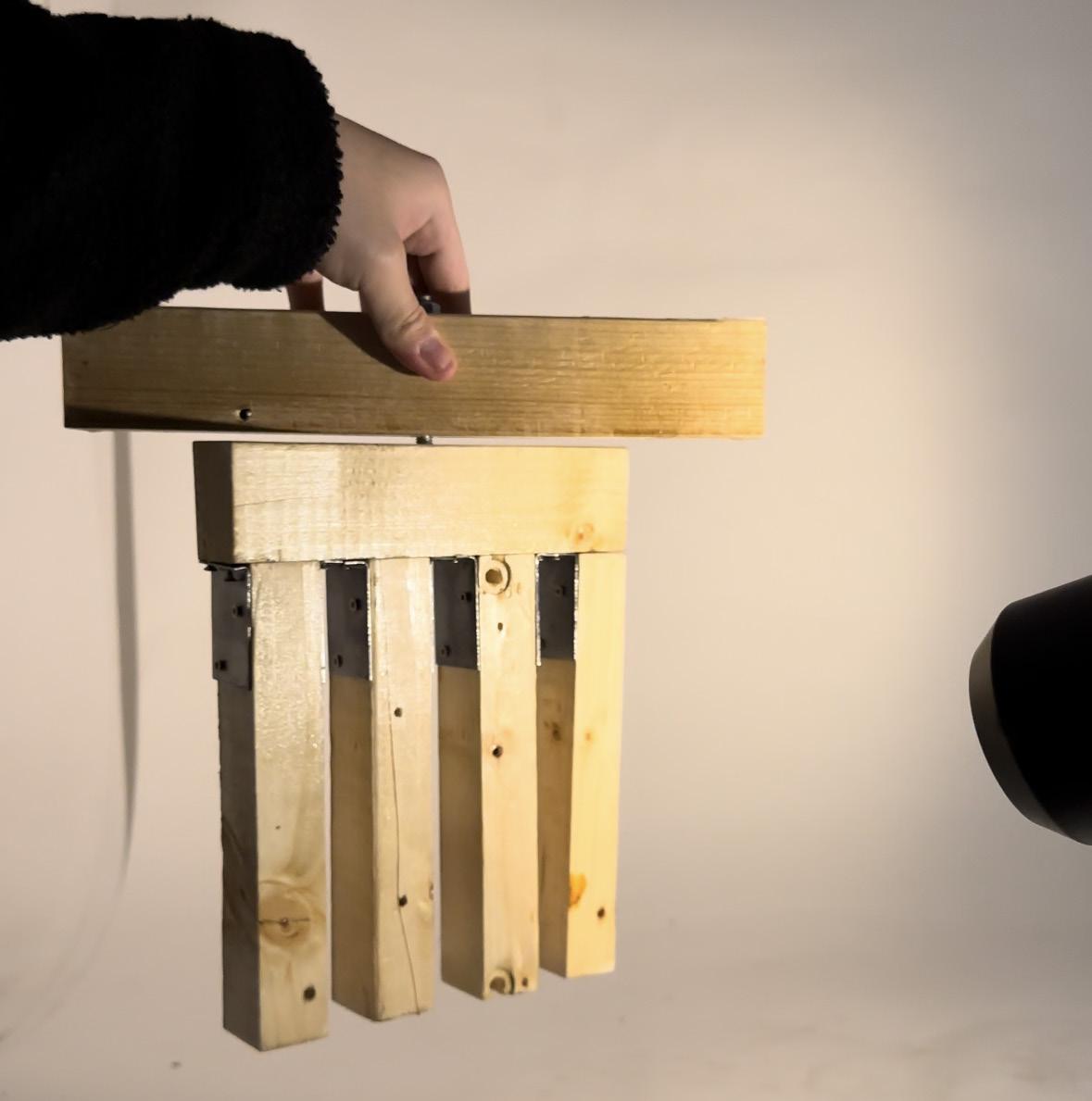
fig 2 : wind speed and gusts (kts).
fig 3 : wind direction mapping.
fig
fig 5 : testing artifact 1:1 with hair dryer (1). fig 6 : testing artifact 1:1 with hair dryer (2).
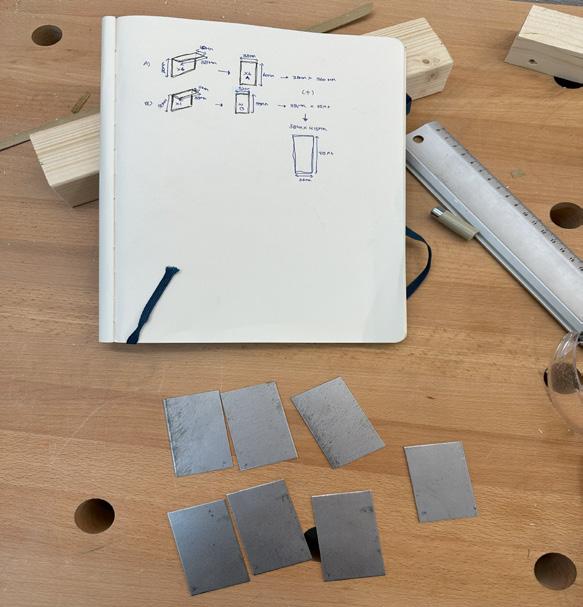
materiality process work - measurements.
LIST
1.Timber (pine wood)
2.Metal (metal joints)
3.Metal (metal tube and bolt)
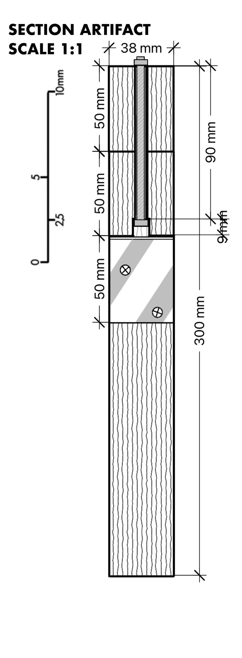
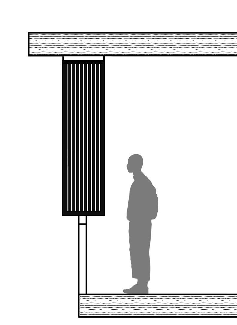
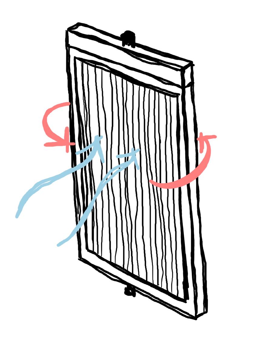
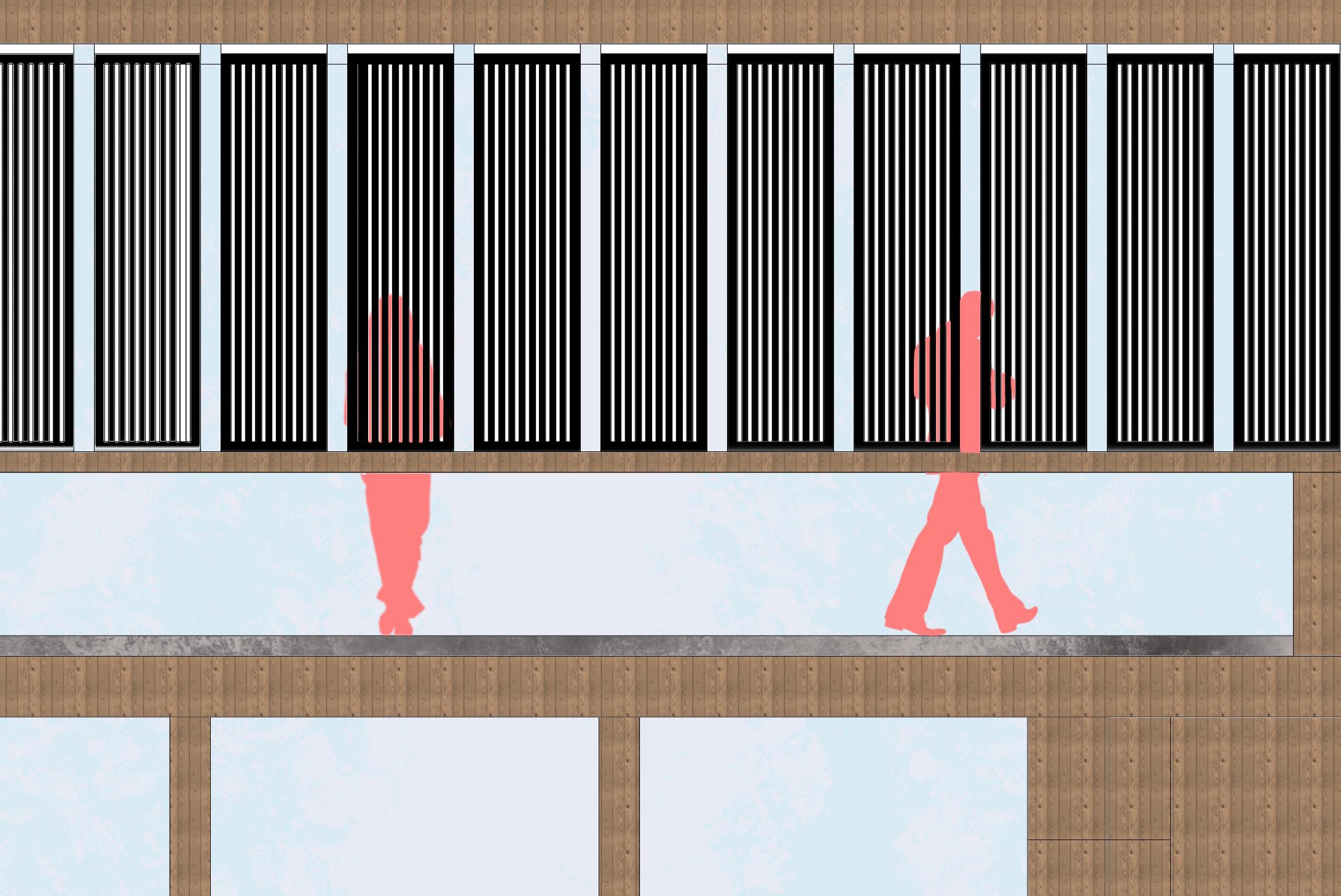
fig 9 : urban scale section.
fig 11 : urban scale elevation.
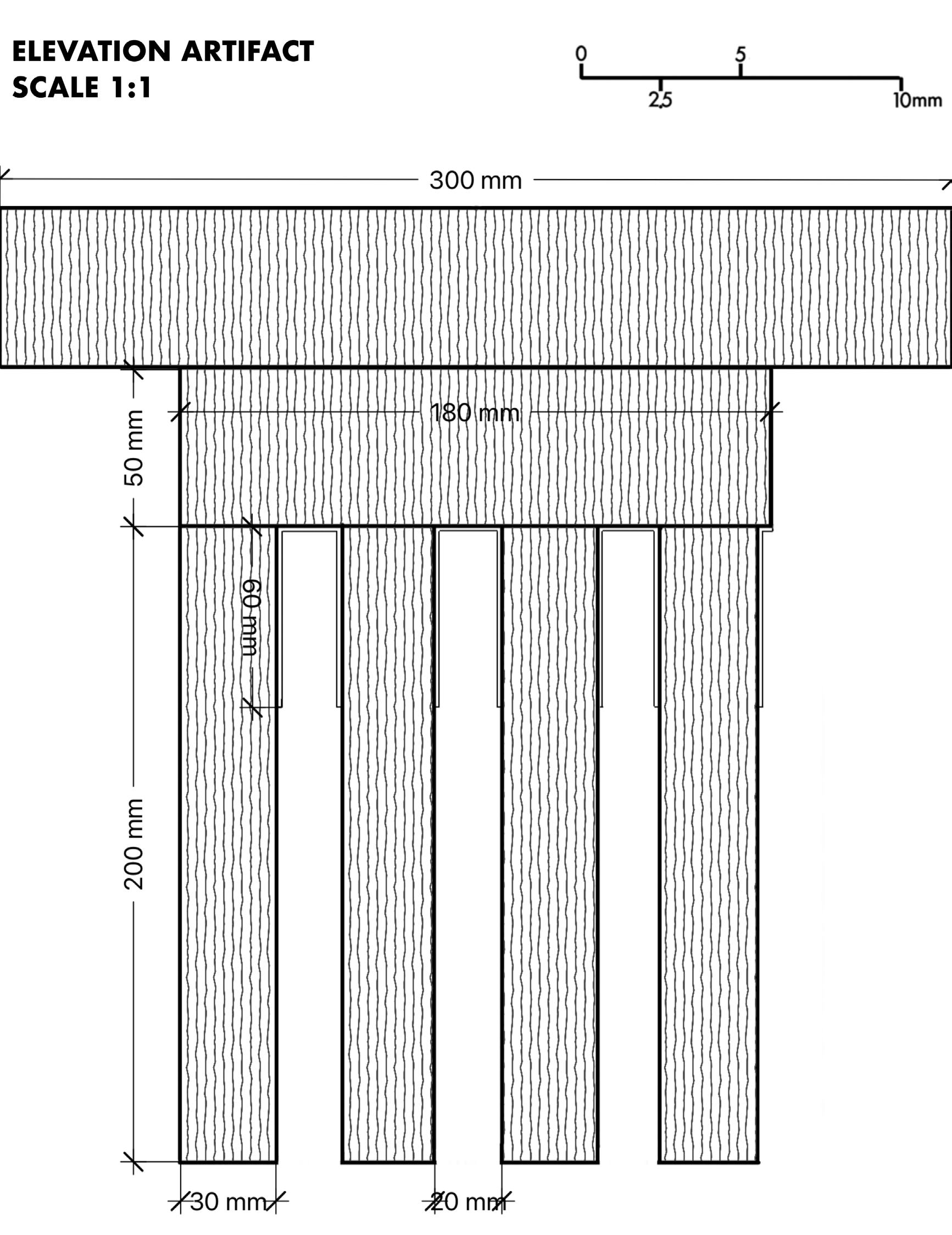
fig 7: elevation of the artifact 1:1
fig 8 : section of the artifact 1:1
fig 10 : understanding how the frame works.
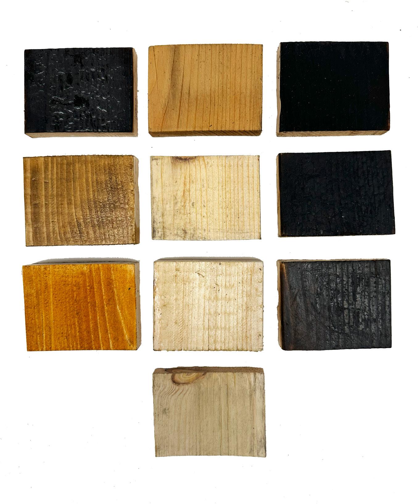
materiality process work - testing materialty.
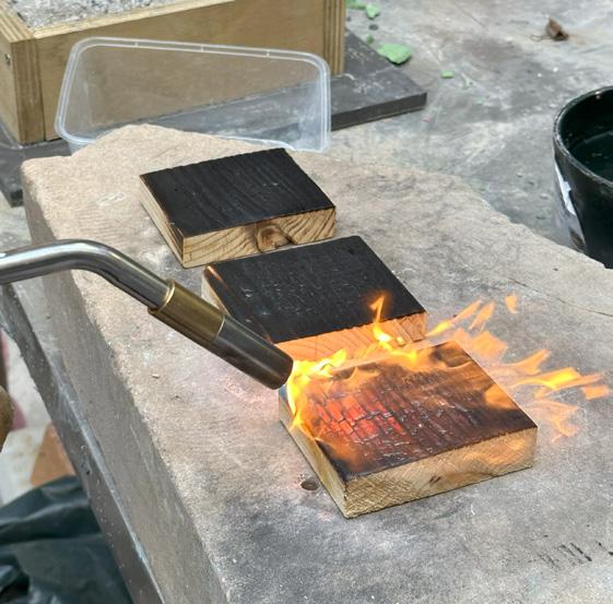
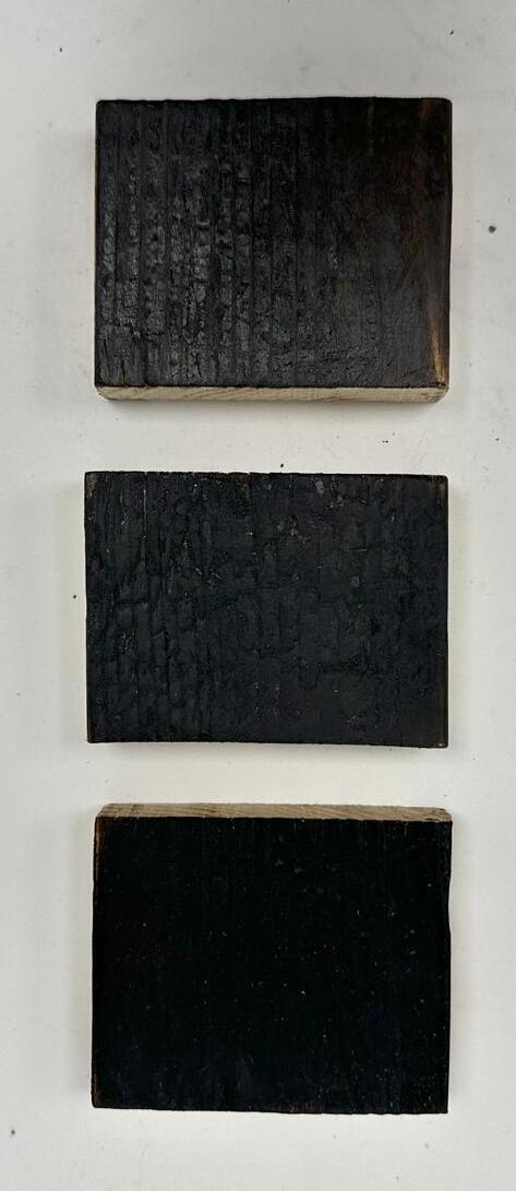
Using butane torch to char the woodto create a natural waterproof finish.
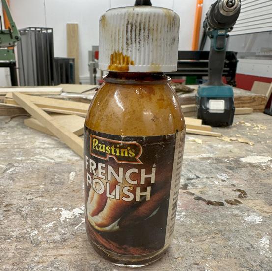
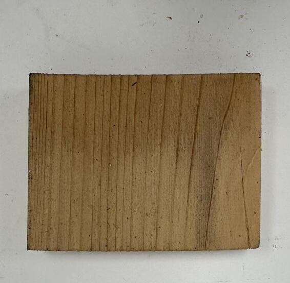
Applying French polish with a cloth and letting it dry creates a glossy shine on the wood.
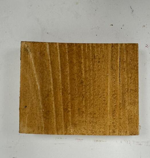
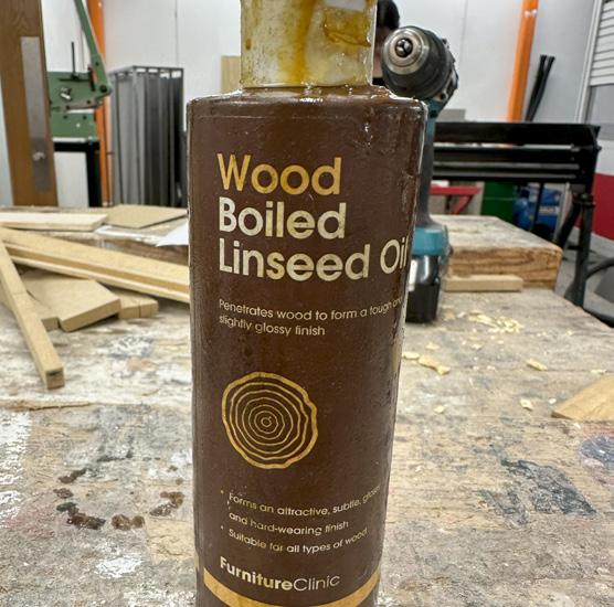
Using cloth to smear the oil and leaving it for around 20 minutes to ensure a protective layer for the wood.
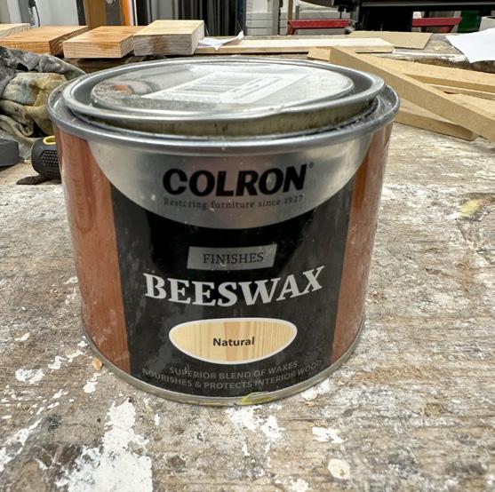
Using cloth to apply the beeswax, leaving it for 15 minutes and applying a second coat, which gives an enhace shine to the wood and add protection.
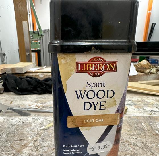
Applying wood dye with cloth darkens the wood, enhancing grain and pores as it absorbs the dye.
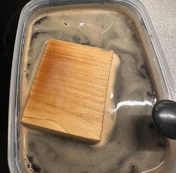
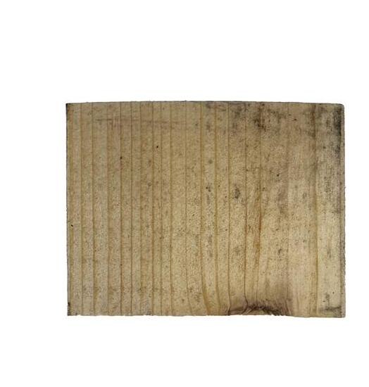
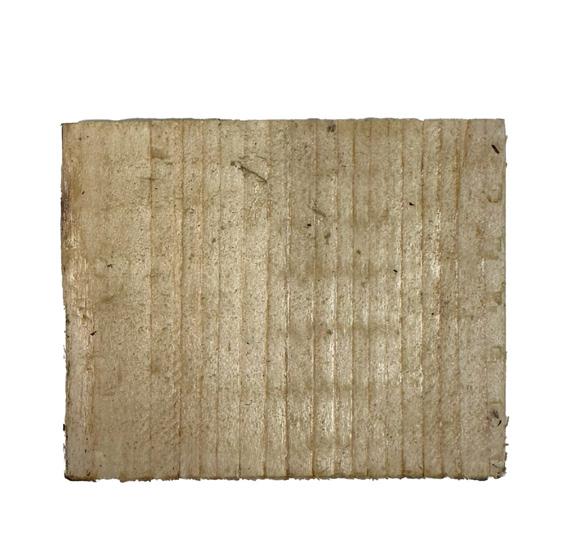
Soaking wood in coffee overnight darkens the pine wood as the grains absorb the coffee.
decision.
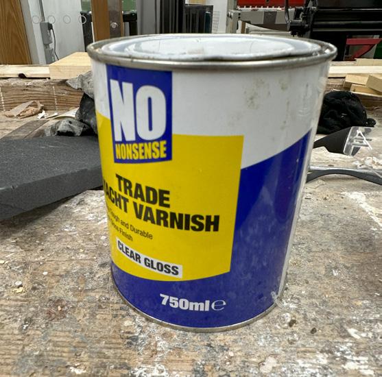
Brushing on a thin layer of varnish provides wood with a glossy finish and protective coating.
The arrangement based on figure 26 are charred with french polish, beeswax, and wood dye oak in vertical order. I decided to pick the french polish one due to giving a deeper shine to the wood grain and charring less. than the picture to keep the wood grain texture.
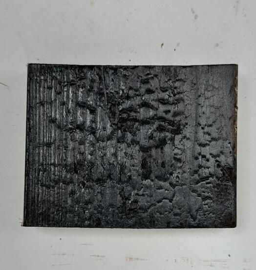
fig 12: charring wood. fig 13 : charred pine wood.
fig 14: wood dye product. fig 15: wood dye pine wood.
fig 16 : french polish product. fig 17: french polish pine wood.
fig 18 : soaking in coffee. fig 19 : coffee soaked pine wood.
fig 20 : lindseed oil product fig 21 : oiled pine wood.
fig 22: varnish product. fig 23: varnished pine wood.
fig 24 : beeswax product fig 25 : beeswax pine wood.
fig 26 : final 3 charred + other finishes
fig 27 : inner layer final decision (varnish).
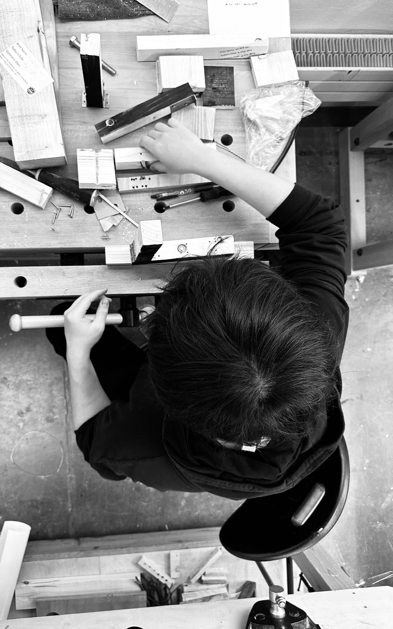
artifact making 1:1 process.
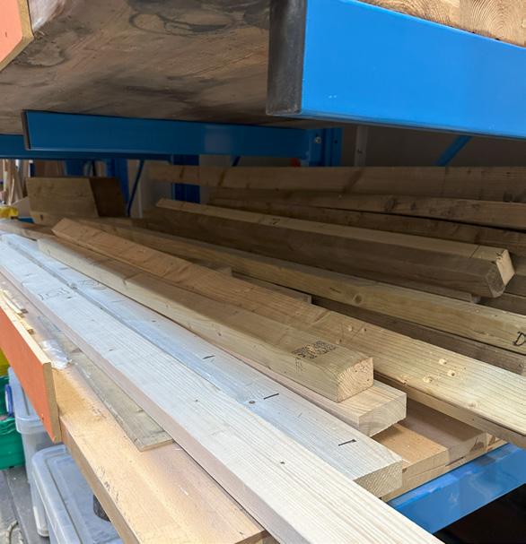
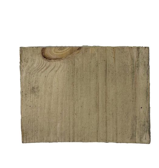
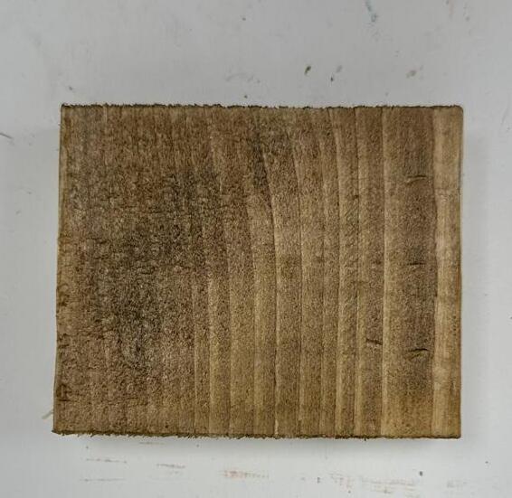
Choosing pine wood slabs (scraps) from the workshop due to its being softwood type and the frame needs to be not densed.
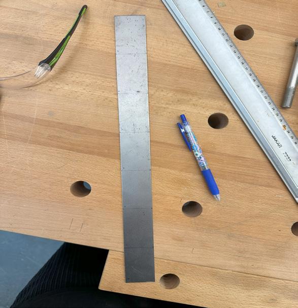
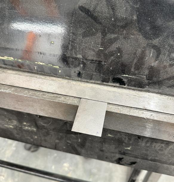
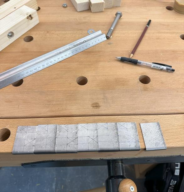
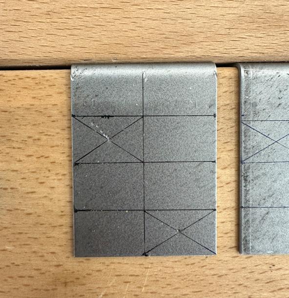
Marking the metal sheets (38mm x 415 mm) into desired size 6 pieces of 38mm x 60 mm and 1 piece of 38mm x 55mm .
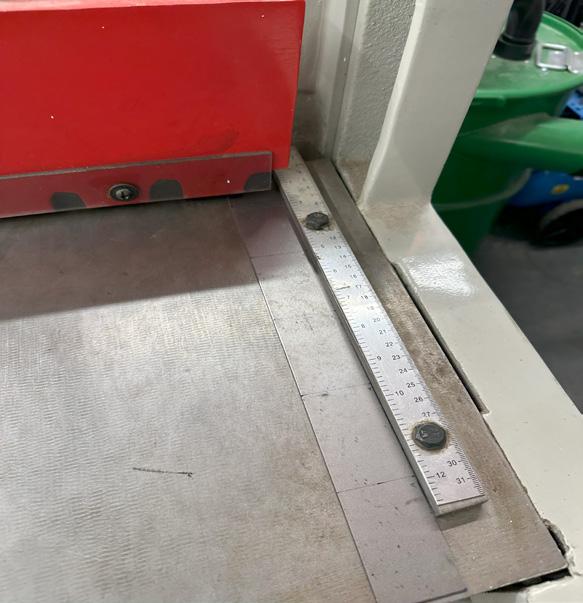
Cutting the metal using guilotine machine in the workshop into the desired size.
Marking 6 pieces of metal sheets 10mm and the last piece 5mm for 90 degree joints.
Bending the metal into a 90 degree angle for joints.
Marking the metal joints for making holes for screws to go into.
Using hammer and metal puncher to make small indetations for the hole.
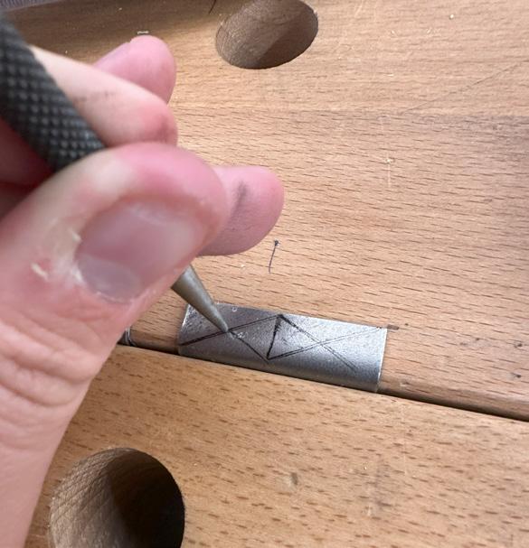
Using hammer and metal puncher to make small holes on the other side of joint.
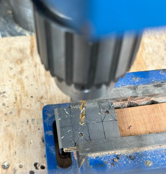
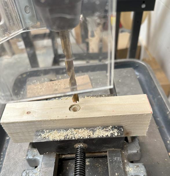
Using a drill machine to make 35mm holes for screws to be placed in.
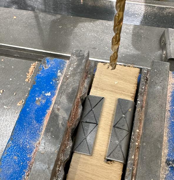
Using a drill machine to make 35mm for the 6 metal pieces and 25mm drill for the last piece because of the small size on one part of the joint.
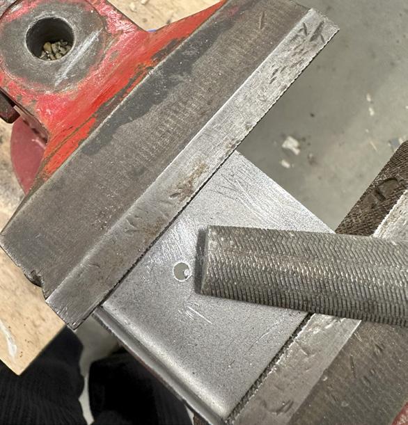
Using metal filer to sand down the imperfections on the holes after using the drill machine.
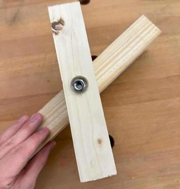
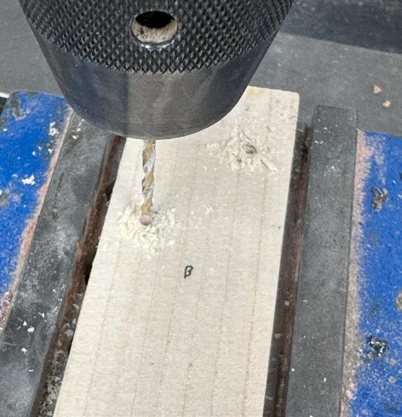
Drilling holes in the centre for metal sticks to be placed in the middle.
Dry fitting the screws o the wood planks for the rotating panel.
Drilling holes (25mm) into the wood for combining the joints and screw together with the wood.
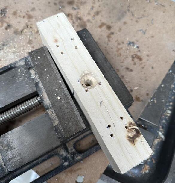
Drilling for the other joints side for joints and screws to stick together with the wood.
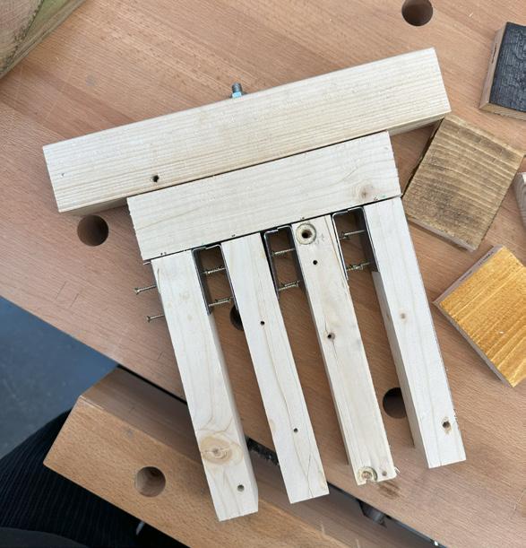
Dry fitting all the metal joints with the cut woods to make sure the measurements are correct.
fig 28 : choosing pine wood from workshop scraps.
fig 32 : bending metal pieces.
fig 36 : drilling metal joints.
fig 40 : dry fitting the timber with the metal tubes and screwing it to place.
fig 29 : marking metal sheets.
fig 33 : marking metal joints for hole.
fig 37 : drilling the other side of metal joints.
fig 41: drilling holes for metal joints to be screwed.
fig 30 : cutting metal sheets.
fig 34 : punching metal joints.
fig 38 : filling the joints.
fig 42 : drilling holes for metal joints to be screwed on the other side.
fig 31 : marking metal pieces.
fig 35 : punching metal joints on the other side.
fig 39 : drilling for metal tube insertion.
fig 43 : dry fitting for final assembly.
artifact making 1:1 process.
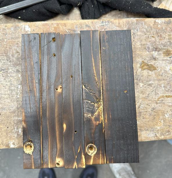
44 : charring the outer layer of the frames.
Learning from the test materials, I decided to char the wood to give a waterproof effect on the outer layers on the wood.
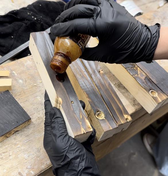
Adding french polish for bringing out the shines and darker finish for wood grains.
final artifact 1:1
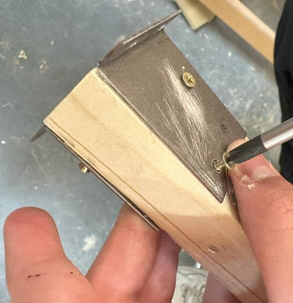
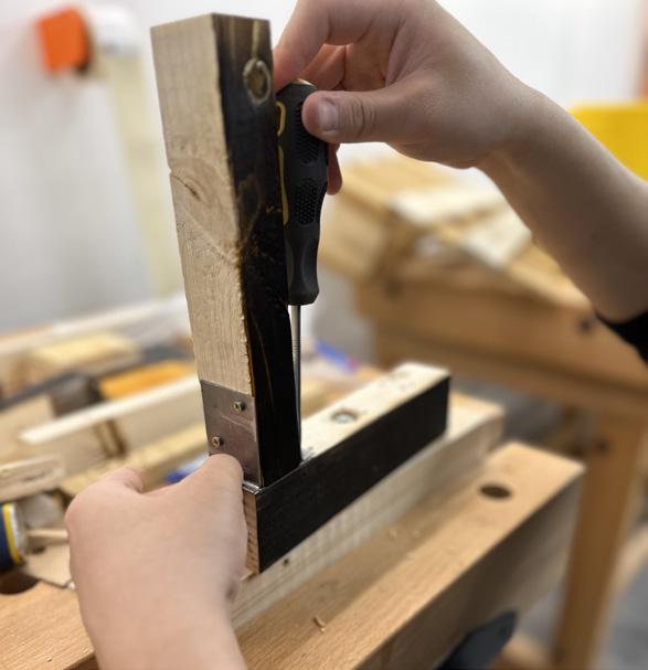
46 : screwing the joints together with the timber frames.
Screwing the joints into the wood sticks.
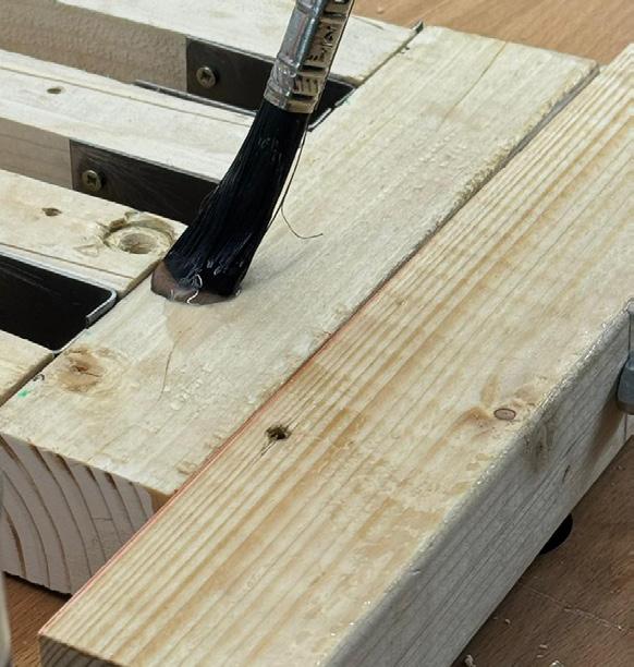
Adding varnish for gloss effect to the model on the inner layers for added protection.
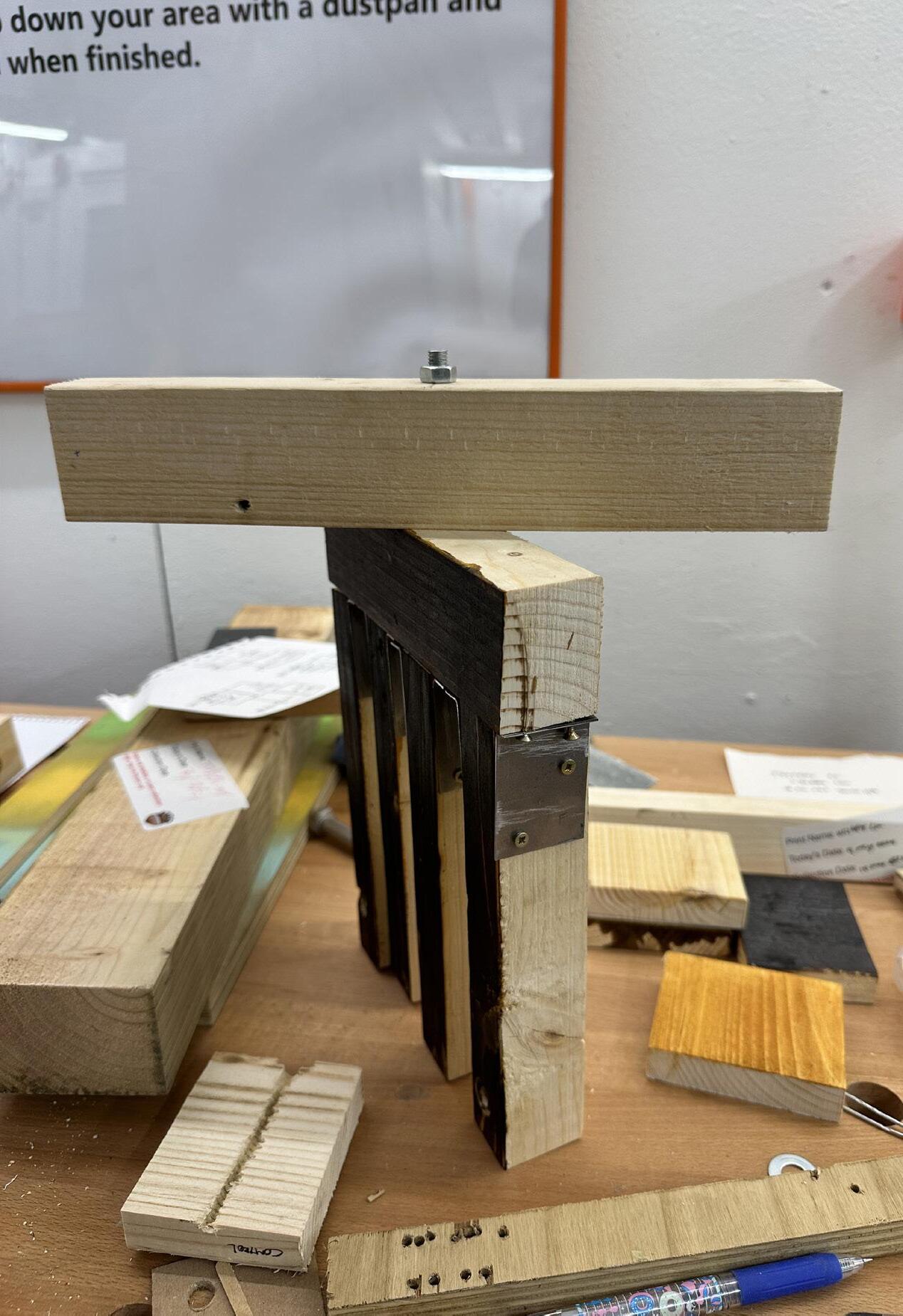
Screwing/combining the wood pieces together.
fig
fig
fig 48 : painting the inside layer with varnish.
fig 47 : combining the model together.
fig 45 : adding french polish into the charred timber frame.
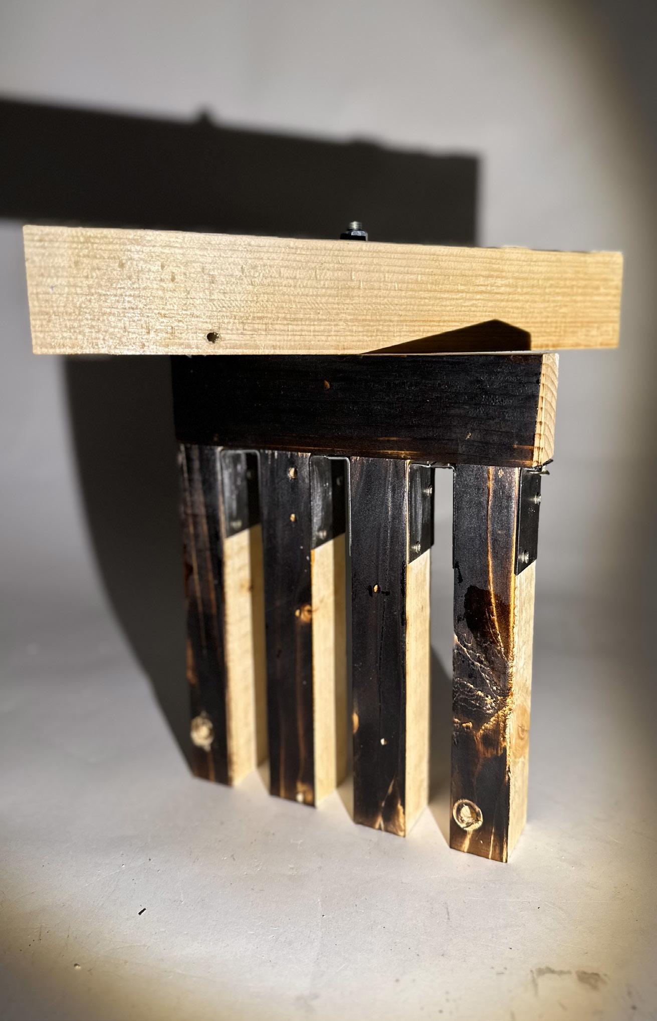
fig 49 : final model assembled.
final artifact 1:1 outcome.
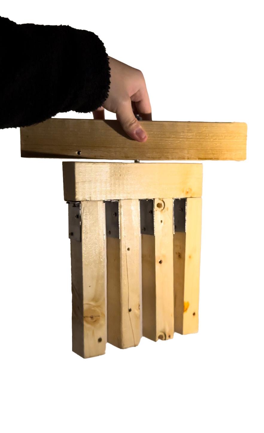
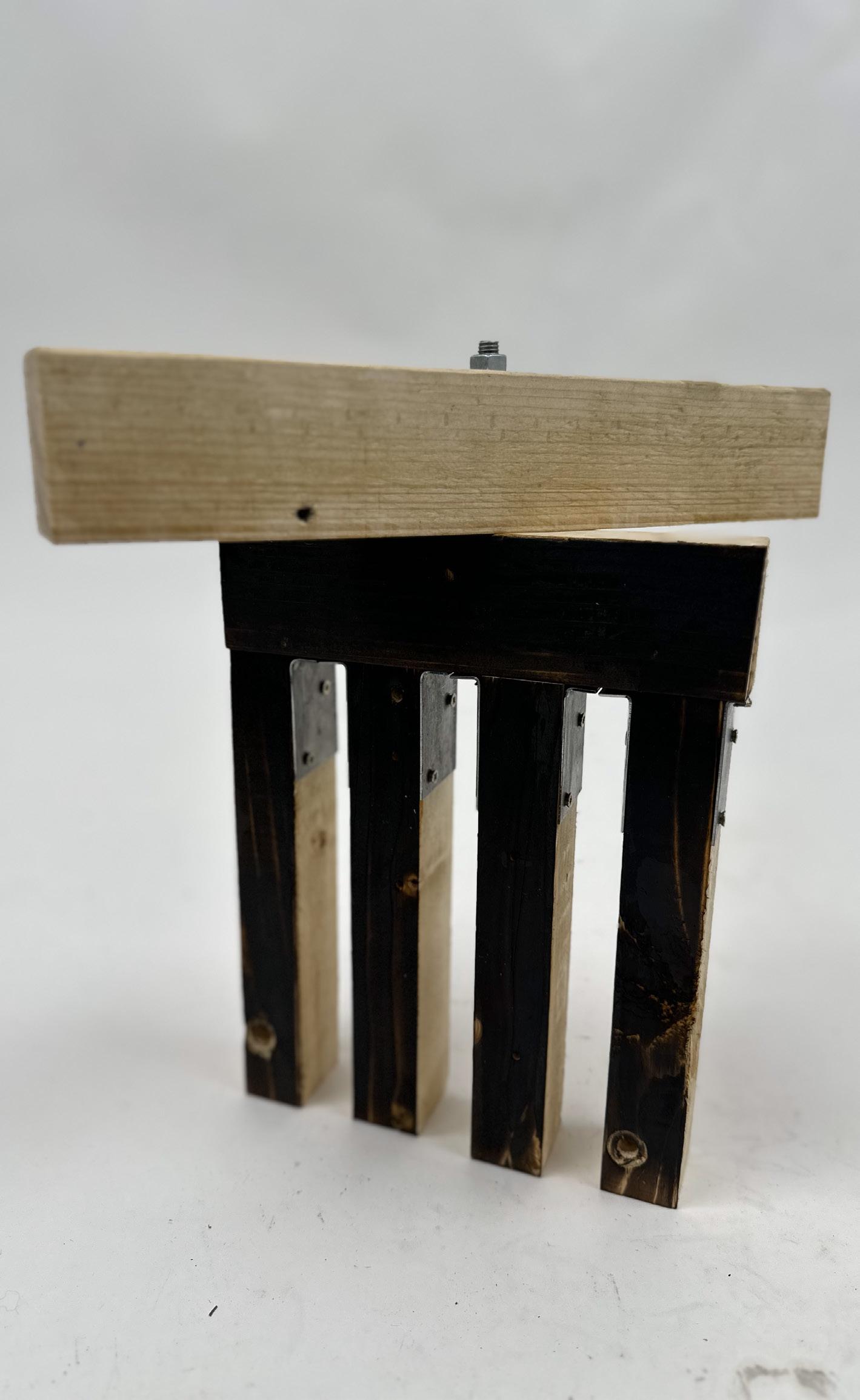
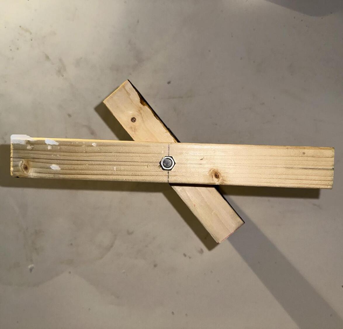
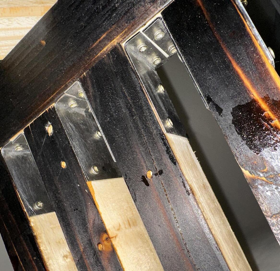
fig 52 : view of the artifact from the top with bolt.
fig 53 : view of the metal joints for the frame.
fig 50 : view of the inside layer of the model.
fig 51 : view of the outer layer of the model.
reflection.
Through doing this project I have regained valuable lessons through experimentation with materiality and gain valuable insight of how climate can change how we design and construct something. From the materiality chapter, I have learned that finishes can affect how it can both protect and change one material texture and looks. For example, pine wood that usually have a light color can be changed into a more darker and glossy finish with french polish, which if you add charring before applying the french polish will make the timber shine more. Furthermore, researching the climate of the site, Northshield located in Newcastle Upon Tyne for design module and implementing the construction part in ARC2017 module to make 1:1 scale artifact that shows a part of the rotating timber frame. This study has also provide me with an image of the contextual backdrop of where to place the panels and how the panels interact with the wind, which was provided from a climatic data to ensure the response of the design with the surrounding enviroment climate. This response of the wind with the rotating panel is simulated using hairdryer as a tool to simulate the wind flow allowed me to ensure that the main function of the model are working as intented and gives me a rough understanding of how the artifact will work in real life.
One of the fun part is during the material testing, specifiacally during the charring of the timber, but I learned after testing the material with the blowtorch that I burned it too far and decided for the 1:1 artifact to char it less than before, which resulted in being able to show the grain of the timber even more. On the other hand, the difficult part when making the artifact is mainly with the metal joints due to never handle metal works before, which I learned by researching and asking the workshop guys with the process of making the 1:1 artifact. Furthermore, using varnish for the inner layer gives a sense of unpredictability due to never using varnish in my life and learned that I supposed to coat it even more lightly than what I did to ensure the surface are covered evenly.
Overall, it was a great experience working this module both for professional and personal work. Through each obstacles that may hinder my progress I have learned to adapt and come up with a solution during working with the unknown materials and it gives me a deeper understanding of the relationship of design, climate, enviroment, and construction. In the future, I would like to test the longetivity of the 1:1 artifact that I have created with other elements, such as human interaction, decaying, and others, which will give me a deeper understanding of the material durability.

bibliography. list of figures.
1. Windfinder.com (no date) Wind and weather statistic north shields/whitley bay, Windfinder.com. Available at: https://www.windfinder.com/windstatistics/north_shields_ whitley_bay (Accessed: 13 May 2024).
2. Inemesit Ukpanah, I. (2024) Is building with wood bad for the environment? stats, trends and facts , GreenMatch.co.uk. Available at: https://www.greenmatch.co.uk/ blog/is-building-with-wood-bad (Accessed: 13 May 2024).
• cover page : author own picture.
• content page : author own picture.
• fig 1 : testing timber finishes, author own picture.
• fig 2 : wind speed and gusts (kts), Windfinder.com (no date) Wind and weather statistic north shields/whitley bay, Windfinder.com. Available at: https://www.windfinder.com/windstatistics/north_shields_whitley_ bay (Accessed: 13 May 2024).
• fig 3 : wind direction mapping, Windfinder.com (no date) Wind and weather statistic north shields/whitley bay, Windfinder.com. Available at: https://www.windfinder.com/windstatistics/north_shields_whitley_ bay (Accessed: 13 May 2024).
• fig 4 : enviromental impact table, nemesit Ukpanah, I. (2024) Is building with wood bad for the environment? stats, trends and facts , GreenMatch.co.uk. Available at: https://www.greenmatch.co.uk/blog/ is-building-with-wood-bad (Accessed: 14 May 2024).
• fig 5 : testing artifact 1:1 with hairdryer (1), authorsown picture.
• fig 6 : testing artifact 1:1 with hairdryer (2), author own picture.
• fig 7 : elevation of the artifact 1:1, author own picture.
• fig 8 : section of the artifact 1:1, author own picture.
• fig 9 : urban scale section, author own picture.
• fig 10 : understanding how the frame works, author own picture.
• fig 11 : urban scale elevation, author own picture.
• fig 12 : charring wood, author own picture.
• fig 13 : charred pine wood, author own picture.
• fig 14 : wood dye product, author own picture.
• fig 15 : wood dye pine wood, author own picture.
• fig 16 : french polish product, author own picture.
• fig 17 : french polish pine wood, author own picture.
• fig 18 : soaking in coffee, author own picture.
• fig 19 : coffee soaked pine wood, author own picture.
• fig 20 : lindseed oil product, author own picture.
• fig 21 : oiled pine wood, author own picture.
• fig 22: varnish product, author own picture.
• fig 23: varnished pine wood, author own picture.
• fig 24 : beeswax product, author own picture.
• fig 25 : beeswax pine wood, , author own picture.
• fig 26 : final charred + other finishes decision, author own picture.
• fig 27 : inner layer final decision (varnish), author own picture.
• fig 28 : choosing pine wood from the workshop scraps, author own picture.
• fig 29 : marking metal sheets, author own picture.
• fig 30 : cutting metal sheets, author own picture.
• fig 31 :marking metal pieces, author own picture.
• fig 32 :bending metal pieces, author own picture.
• fig 33 : marking metal joints for holes, author own picture.
• fig 34: punching metal joints, author own picture.
• fig 35 : punching metal joints on the other side, author own picture.
• fig 36 : drilling metal joints, author own picture.
• fig 37 : drilling the other side of metal joints, author own picture.
• fig 38 : filling the joints, author own picture.
• fig 39 : drilling for metal tube insertion, author own picture.
• fig 40 : dry fitting the timber with the metal tubes and screwing it into place, author own picture.
• fig 41 : drilling holes for metal joints to be screwed, author own picture.
• fig 42 : drilling holes for metal joints to be screwed on the other side, author own picture.
• fig 43 : dry fitting for final assembly, author own picture.
• fig 44 : charring the outer layer of the frames, author own picture.
• fig 45 : adding french polish into the charred timber frame, author own picture.
• fig 46 : screwing the joints together with the timber frames, author own picture.
• fig 47 : combining the model together, author own picture.
• fig 48 : painting the inside layer with varnish, author own picture.
• fig 49 : final model assembled, author own picture.
• fig 50 : view of the inside layer of the model, author own picture.
• fig 51 : view of the outer layer of the model, author own picture.
• fig 52 : view of the artifact from the top with bolt, author own picture.
• fig 53 : view of the metal joints for the frame, author own picture.
• reflection page : author own picture.