


VOL 140 PART 4 OCTOBER 2022 FELIX S&C LASER PROFILE MEASURING SYSTEM 30 ADVANCES IN ENGINEERING SURVEY GRID TRANSFORMATIONS FOR RAIL INFRASTRUCTURE 20 IMPROVING TRACK WORKER SAFETY WITH GEO-FENCING 10 LEARN WITH US TRAINING DELIVERED BY INDUSTRY EXPERTS 66 ELECTRIFICATION COST REDUCTION –DIGITAL DESIGN & CHALLENGING THE RULES 46 PWI ANNUAL MEMBERSHIP £90 4 ISSUES OF THE JOURNAL ANNUALLY (£15.00 PER ISSUE FOR NON MEMBERS) WELCOME PETER 9 BACK TO BASICS –POINTS PART 1 OF 2 12 1
It is with sadness and much affection that we record in this Journal the death of Her Majesty Queen Elizabeth II on 8 September 2022. Doubtless, members will already have seen many commemorations and tributes published in the general media. Our intention is not to replicate those here but to pay tribute to Her Majesty in the context of our industry.
Queen Elizabeth’s 70-year reign encompassed many revolutionary changes in the UK’s railway industry. In addition to the many technological advances and improvements in rail transport, the role of railways in the life of the kingdom underwent a fundamental realignment over those years, including the abandonment of most of the rural railway network.
Throughout her reign the Queen maintained an active engagement with the railway industry. The photo above captured the spirit of that engagement, and the pleasure and pride it engendered within the railway engineering community. We are proud and grateful that Her Majesty chose to maintain her involvement with the UK railway community until the end.


2
Her Majesty The Queen with the people that rebuilt Reading Station. (Photo courtesy of Network Rail)
Apprentice, Student £0 e-Journal £25 printed Journal

Member £90.00
Member (66.5 or older at 01.01.22) £37.00 EngTech Member* £90.00 IEng/CEng Member* £143.00 Fellow £122.00


Fellow (66.5 or older at 01.01.22) £48.00
EngTech Fellow* £122.00 IEng/CEng Fellow* £191.00 CORPORATE MEMBERSHIP

Sml enterprise (Turnover up to £17.5m pa) £2,200 Med enterprise (Turnover £17.5m - £200m pa) £5,500 Lrg enterprise (Turnover above £200m pa) £11,000 Heritage railway £150

CONTENTS 2 Queen Elizabeth ll 1926 - 2022 4 We always come back to S&C and its challenges! 6 Strategically speaking 9 Welcome Peter 10 The PWI’s Climate Change & Decarbonisation Committee 12 Back to basics – Points Part 1 of 2 20 HS2 - Advances in engineering survey grid transformations for rail infrastructure 25 New PWI Training Course For 2023 - Advanced Track Technician Course 26 Improving track worker safety with geo-fencing 29 New PWI Training Course For 2023 - Earthworks, Drainage & Off-Track Engineering Course 30 Felix S&C Laser Profile Measuring System 40 Tomorrow’s Rail: Safety Today - PWI Technical Seminar Report 46 Electrification cost reduction Digital design & challenging the rules 51 #PWIElectrify 54 Professional registration 58 PWI Technical Seminar - Sustainable Infrastructure: Design & Maintenance 61 Corporate Members and Technical Board 62 Our people 64 Section contacts 66 Learn with us - PWI technical training 68 PWI Technical Seminar - Railway Infrastructure: Delivering Digitally THE JOURNAL OCTOBER 2022 VOL 140 PT 4 THE COPY SUBMISSION DEADLINE FOR THE NEXT JOURNAL IS 1 NOVEMBER 2022 COPY / ADVERTISING DEADLINES & ENQUIRIES January 2023 DEADLINE - 1 November 2022 April 2023 DEADLINE - 1 February 2023 July 2023 DEADLINE - 1 May 2023 October 2023 DEADLINE - 1 August 2023 Kerrie Illsley, Creative Manager, journaleditor@thepwi.org THE PERMANENT WAY INSTITUTION PWI Central, PO Box 12890, Brentwood,
9RY
230 031 / www.thepwi.org / secretary@thepwi.org PLEASE NOTE: Every care is taken in the preparation of this publication, but the PWI cannot be held responsible for the claims of contributors nor for the accuracy of the contents, or any consequence thereof. CBP010491 ISSN 2057-2425 Publishing and layout by Permanent Way Institution
CM14
+44 1277
INDIVIDUAL MEMBERSHIP
REGISTRATION
FEE: New Registrant**
Additional Membership
CATALOGUE Did you know that there’s a Journal catalogue on the PWI Website? It holds a comprehensive list of every technical article published in the last few years. This chronological list
the article
Knowledge Hub. SHARE YOUR KNOWLEDGE Whether you come from an academic or industry background, or a combination of both, if you are an expert in your field then we would love to hear from you.
your idea with us for a new technical article and our Technical Content Manager will get in touch to start the process.
it towards the bottom of this page:
3
PROFESSIONAL
APPLICATION
EngTech £60 / IEng £225 / CEng £225 APPLICATION FEE:
EngTech £40 / IEng £90 / CEng £90 EngCouncil Fee* EngTech £20.30 / IEng £35.40 / CEng £41.72 * If you are professionally registered through the PWI the annual Engineering Council Registration fee will be collected in addition to your PWI subscription and will be paid to the Engineering Council on your behalf. ** Includes the Engineering Council Registration Entry fee. 2022 PWI ANNUAL SUBSCRIPTIONS JOURNAL
links directly to
over in the
Share
Email journaleditor@thepwi.org Find
www.thepwi.org/the-journal/
WE ALWAYS COME BACK TO AND ITS CHALLENGES!
All rail infrastructure whether it’s the wires, rails, ballast, signals, or structures has an interface with switches and crossings! It is no surprise that we get excited about S&C as it is the only way to get from one track to another and when it gets worn, we must sort it out! This summer has been one of challenges for rail staff and my travels involved discussing S&C with likeminded engineers in France, Scotland and of the course at our main centre, Derby.
The excellent and keen Scots from Perth, led by Brian Leyden, were, I think a little surprised and possibly dumb founded by the various types we discussed with them in August. I can’t wait to hear what the team leaders told their teams when they got on to their next job in S&C refurbishment. We had a great chat about forces, loading and degradation and hopefully they went away with some of the skills to spot problems and find ways to rectify them.
This leads me on to social media and the amazing platform “LinkedIn” which keeps us all in touch with each other especially in the PWI! I followed Jamie Lovegrove, a PWI member from London who is the Network Rail Section Supervisor and was very proud of his team at Camden Pway depot and the job they did at Gunnersbury on the North London Line last month.
They replaced a right-hand half set of switches at Gunnersbury junction; 101 points. The history is that they got a report of severe foot corrosion to the switch with three spots approximately the size of a golf ball. When reviewing against rail inspection standards it turned out to be a 5A defect which was a rail change within 48 hours. So, it was all hands to the deck, and they got an emergency possession and a new switch delivered to site within 24 hours and were able to install the new switch before the 48th hour was up. Well done to all involved. See images below.

Jamie said “The site is prone to flooding due to being in a cutting with high banks either side. Because of this there was great difficulty removing the clips from their housings, but with great force and determination we freed them up, as well as dealing with problems of delamination of the foot and web of the rail. It is clearly a lesson learnt that we need to increase inspection for rail foot corrosion in high-risk flooding areas.”
 Gunnersbury Junction North London line (courtesy Jamie Lovegrove)
Gunnersbury Junction hard work to position the switch! (courtesy Jamie Lovegrove)
Gunnersbury Junction North London line (courtesy Jamie Lovegrove)
Gunnersbury Junction hard work to position the switch! (courtesy Jamie Lovegrove)
4
TECHNICAL
I hope you continue to appreciate our range of technical articles, carefully collated by Mike Barlow, the PWI Technical Manager, and any suggestions will be warmly received for any new areas.

We have been involved in two seminars in Birmingham, the PWI May Safety Seminar and the Network Rail Track Maintenance Engineers Conference. They were both excellent in content and Birmingham was a highlight for me with as usual many outstanding contributions. It was good to welcome non engineers to promote safety behavioural change as sometimes we are blinkered when we are too close to the “coalface” and we have much to learn from other industries and organisations. The TME’s benefitted from many informative sessions on track integrity problems and were introduced to many new innovative maintenance techniques with a supplier showcase.
REFLECTION
I have no problem in identifying my favourite PWI day since I last wrote. This was Rail Live at the Long Marston Quinton Rail Innovation Centre near Stratford upon Avon. The set-up was magnificent with many large plant exhibits and smaller companies demonstrating their wares. There is always something new and exciting and this time for me it was the Network Rail asset system which has developed enormously since my days in Infrastructure Maintenance of the Midland Main Line.
We were given our challenges on 19 July this year when after all the predictions we finally recorded very high temperatures in the UK. It was 40.3°C and was recorded at Coningsby in Lincolnshire which was the centre of the so-called dome of heat which moved north from Europe.
The railway coped very well and there were few problem areas. We came close to “blanket” speed restrictions but the heatwave only lasted three days. It was a good test of our systems and readiness, and it is good to promote new systems such as the railway “heat map” pioneered by Network Rail. Interestingly the hotspot is close to where I live in Belper, Derbyshire (see image 1 above).

I was delighted to return to face-to-face conferences in August with a trip to Railways 2022 in France. The PWI was well represented with our President giving the keynote address. The subject areas were varied with a high focus on electrification and track. I presented on the challenges of heat management on track and earthworks. We will publish some of the papers in the next few Journals.
AND FINALLY...
To finish my summer, my annual pilgrimage is to Barmouth and to visit the bridge which I worked on in the 1980’s. A huge amount of work has been done to stabilise the timber section and I was very impressed by the complex engineering input which will last at least 50 years! Next year, the metal part will be renewed so I look forward to seeing that as well (see image 2 above).
TECHNICAL DIRECTOR technicaldirector@thepwi.org
 Image 1: Heat Map (courtesy Network Rail)
5
Image 2: Barmouth Viaduct timber track replacement (courtesy Brian Counter)
STRATEGICALLY SPEAKING
Next year, 2023, will be the last within the PWI’s current five year, 2019-2023, strategic plan. 2023 will also be the year in which the PWI develops its successor strategic plan, which will run from 2024 to 2028and beyond. So, why do we need a strategy?
Whilst the term strategy can induce a degree of scepticism in some people, I can only point to the growth and success of our Institution over the last 10 years; through two successive 5-year strategic plan periods. The PWI’s achievements, delivered through the focussed pursuit of wellthought-out strategies, include:

• gaining our Engineering Council licence - the ability to award professional engineer status to our individual members;
• through corporate membership, enabling industry bodies and companies to play a direct role in the life of the Institution;
• growing our support for the electrification engineering community;
• expanding our education and training programmes;
• our membership of the Joint Board of Moderators;
• the new PWI website and Knowledge Hub, and;
• our recognition of decarbonisation and climate change adaptation, and diversity and inclusion as critical areas of policy and practice.
Without these achievements the Institution today would be less relevant and less capable of giving its members the support they require and deserve. To be delivered effectively and efficiently, continued improvements in the support and services the PWI offers its growing membership must be underpinned by an updated strategy.
The PWI has changed significantly since 2018, the year the current plan was created: it is a larger organisation; the volume and scope of its activities have grown; it has many more members, both individual and corporate; and it exerts greater influence, within both the railway industry and the wider engineering community. The process for developing our strategy must reflect these changes and the PWI Board is particularly keen that the strategy is developed in consultation with all the Institution’s stakeholders.
This article is the “opening shot” in our plan to ensure that members and others involved in supporting the PWI have opportunities to contribute to drawing up this strategy. I have outlined below the development process we intend to follow, highlighting those opportunities, and inviting stakeholders to contribute their perspectives and ideas.
6
Development of the new strategy will run in four phases.

• Firstly, between now and late November the executive team will develop a set of questions and initial thoughts to stimulate strategic discussion on the future direction of the PWI: outcomes we might achieve - and how we might achieve them. We will also set out a programme of structured consultations, both face to face and online, providing forums for key stakeholder groups to discuss that material and bring their own perspectives and priorities to bear.
• Secondly, from December through to mid-2023 we will run those consultation events and invite individual written contributions. Using the output from this wide consultation and working closely with the Board, we will determine the outcomes the Institution should seek to achieve, identify the related areas for strategic development and change, and prioritise them for delivery.
• From mid-2023 to late Autumn we will turn those priorities into proposed resourced and costed work programmes, then put these to the Board for agreement in principle.
• Finally, from November 2023 to February 2024 we will refine those programmes, building them into the PWI’s integrated budgets and physical plans. In February 2024 I will ask the Board to endorse those budgets and plans.

Getting consultation, the second stage of the process, right will be hugely important in ensuring we make the most of the collective experience and wisdom of our members and supporters. Understandably, we intend to make use of established forums (including Vice Presidents’ meeting, Section Secretaries’ meeting, Technical Board, Diversity and Inclusion Committee, and Decarbonisation Committee).
We will include a review of feedback from previous discussions with members, including Membership Director Joan Heery’s extensive work with corporate members.
Additionally, we intend to convene special face-to-face and online events to capture the ideas and views of the wider membership: particularly those, such as Section Committee members, who have hands-on experience of making the Institution flourish at local level; and our professionally registered engineers, who are integral to the Institution’s place within the “club” of professional engineering institutions. Fellows’ and senior members’ input, representing the thinking of influential industry engineers and managers, will be enormously helpful as will input from our apprentices and students - the future of the PWI! Individual written submissions will, of course, be very welcome.
To summarise, the new strategic plan will be central to maintaining the Institution’s “development momentum” and making member support and services even better. I look forward to your contribution.
Stephen Barber CEO stephen.barber@thepwi.org
structured
PHASE 1 September 2022 –November 2022 Develop briefing pack. Set up programme of
consultation events.
PHASE 2 December 2022 –June 2023 Hold consultation events. Use output to determine outcomes, development actions, and priorities.
work
PHASE 3 July 2023 –November 2023 Develop resourced and costed
programmes. Board approval in principle
OF PWI STRATEGIC PLAN FOR 2024 – 2028 & BEYOND 7
PHASE 4 December 2023 –February 2024 Build work programmes into PWI integrated budgets and physical plans. Board endorsement of budgets and plans. DEVELOPMENT
www.railcare.co.uk
MAINTAIN THE QUALITY OF YOUR RAILWAY TRACKS
Using grinding, reprofiling and deburring machines, semi automatic large grinding machines and road-rail grinding vehicles
Goldschmidt maintains the quality of your railway tracks – quickly, efficiently and with precision. Well-trained, experienced grinding teams offer flexibility.


The VM8000 grinding vehicle is fully certified to RIS-1530-PLT Issue Six. Find out more at www.thermit-welding.com
www.goldschmidt.com

The Railvac and Ballast Feeder System industry concept delivers increased re-ballasting capacity. Always non-intrusive, with the track in situ and without disconnections!
8
Welcome Peter
Behind that sits the need to redefine what the railways are for. Sixty years ago Richard Beeching set out in his report “The Reshaping of British Railways”. What he proposed has driven the path for six decades. We now have a passenger railway which provides for freight at the margins. Post-Covid and post-fossil fuel that balance must surely change - we need a 21st century “Reshaping of Britain’s Railways”.
That reshaping has already started organisationally. The publication of the integrated rail plan and the formation of the Great British Railway Transition Team are evidence of that.
people across the age range and across all rail infrastructure disciplines. Bigger membership numbers will open the way for improved services to all. I know some will find the changes in the Institution to be unsettling, but nothing will be lost, the changes only add to the value of membership.

On 8 July at the AGM in Birmingham I was formally confirmed as President of the PWI. That is an honour I never anticipated, and brings with it a responsibility to serve the Institution and its members which I take very seriously.
I have taken up that role against the background of some momentous events. Two years of Covid restrictions seem now to be behind us, but the aftermath of the pandemic is still with us.
The virus has not gone away, it seems we are learning to live with it. However, it would be wrong to ignore the changes in travel patterns that Covid has driven. For the railways, the loss of revenue will bring lasting and deeply challenging economic pressures.
Attention to our climate and the rise in global temperatures has for many years been treated as tomorrows problem, other countries suffer, not us. But summer 2022 has marked record temperatures and wild fires. Flood risks were all too evident during past winters, while drought conditions now increase the stress on the ageing earth works on which our railways are built. Sea defences have already failed in places, and as sea levels rise they become more exposed. The lack of resilience of the rail infrastructure is increasingly obvious.
Network Rail have set up a task force to look at resilience, of which I am a member.
No one can reasonably deny that climate change is real, and the science emphatically proves that greenhouse gas emissions due to human activity is the cause. Humanity has to stop those emissions. Rail can play a pivotal part in the national response, but to achieve that requires changes that will need investment, big investment.
That said, what can the PWI do in those enormous issues.
My Presidency will centre on four things:
1. Developing and growing the PWI.
2. Placing the railways at the centre of the strategy to decarbonise transport.
3. Helping to increase awareness and understanding of what must be done to protect the railway in a hotter world.
4. Increasing the influence of Railway Infrastructure Engineers in strategic decision making.
As an Engineering Council registered Professional Engineering Institution (PEI) our Institution has a growing number of Engineers and Technicians with Professional Registration gained through the PWI. As a relatively small PEI the PWI must carefully focus its efforts to achieve maximum impact, and we do so extremely effectively. This is evidenced by the immense range of membership support including the excellent new website, training and educational services, meetings, conferences and seminars that we provide.
In one very important respect, the PWI are unique. We are the only PEI which has a single focus on the whole railway infrastructure.
Over recent years my own discipline, traction electrification, has become a more significant part of the membership. I will be working with the PWI team to grow membership numbers by broadening the Institutions appeal to
In terms of the outward facing influence of the PWI I will continue to advocate and support the development across some big picture policy and strategy issues. The challenge for our railways is to maximise the benefits of rail in providing clean, carbon zero capacity to encourage and facilitate a modal shift from road to rail. Whilst that shift is important for passenger travel, trunk haulage of freight is at least as important. Clearing some strategically important routes to an appropriate freight gauge is essential to open the railway for container traffic growth. The rail freight industry is already investing in new electric locomotives, so the strategy must be combined with the roll out of electrification across much more of the railway.
Climate change also changes the stresses on the railway. In February 2014 storms and high winds at Dawlish washed away the main line. Sustained heavy rain and resultant flooding, coupled with inadequacies in the drainage system made Carmont the scene of tragedy in August 2020. Summer droughts are accelerating the drying out of already aging earth works, increasingly high summer temperatures are resulting in more train service disruption when track and overhead lines become affected by heat and autumn storms expose the risk of lineside trees falling on to tracks.
I will be supporting consideration of how the industry moves to a proactive position to better protect the railway.
I will give voice to advocating the vital role of engineers in defining the measures to address all of those challenges. My argument is that in the drive to improve project and commercial management, engineering input and influence has been reduced, I will positively seek to highlight the need for a rebalancing. Particularly I will take every opportunity to place railway infrastructure engineering, and the expertise of all those who work in the field as key to the solutions.
I thank everyone in the PWI for the opportunity you have given me.
9
Peter Dearman PRESIDENT The PWI
THE PWI’S CLIMATE CHANGE & DECARBONISATION COMMITTEE
Our new President, Peter Dearman has made it very clear in his inaugural Journal article of the importance of climate change adaptation and decarbonisation in relation to railway infrastructure and this subject will form a core part of Peter’s work during his presidential term.
Peter makes the specific point about rail infrastructure engineers having an increasing influence in strategic decision making and although he has not referenced it, Peter has been a member of a National Engineering Policy Centre (NEPC) working group looking at the role of hydrogen in a net zero energy system.
In September, the working group issued their final report on the subject and it can be accessed via raeng.org.uk (see QR code below).

Reading the report is useful CPD activity and it’s wonderful to see both Peter and the PWI referenced as contributors. The report examines the suitability of hydrogen for major applications across the economy, including industry, power, transport, heat and buildings. It recommends that while the best use of low-carbon hydrogen has yet to be determined, low-carbon hydrogen should be available for the end uses in which hydrogen deployment has the potential to become the best or only low or zero-carbon option available.
The NEPC’s analysis highlights, for example, that hydrogen is likely to become the most effective or the only viable decarbonisation option for some end uses such as primary steelmaking, industrial heating and as a chemical feedstock for industrial process. This will maximise hydrogen’s value to decarbonisation of the whole energy system and to closing the emissions gap to put the UK on track with its Fifth and Sixth Carbon Budgets and the 2050 net zero target.

https://raeng.org.uk/media/tkphxfwy/the-role-of-hydrogen-in-the-net-zero-energy-system.pdf
SEPTEMBER 2022 10
The role of hydrogen in a net zero energy system
You may recall in the April Journal, I included information on two videos the NEPC had produced in relation to Net Zero. An additional three videos have been completed which cover Energy, Transport and Implementation. The series investigates the engineering, policy, and human realities of a just transition to a net zero emission world - a transition that not only helps avert disasters but also brings real benefits to all. The videos are intended to inspire and provide knowledge; you may find them beneficial for use in team situations or your own personal viewing. Links to all five videos are provided via QR Codes to the right.
Two members of the PWI’s CCA & Decarb Committee, Chrisma Jain and Matt Gillen, have been leading a piece of work on how the PWI should respond to changes in UK SPEC (Engineering Council 4th Edition) where sustainability has a much greater focus as part of the professional registration process.
Chrisma and Matt have formed a small working group and have considered minimum scoring requirements for each grade of membership, annual CPD requirements and are in the process of developing specific exemplars in relation to rail infrastructure to help both candidates and reviewers.

We need to get to a place where sustainability considerations sit alongside safety, recognising it has taken many years of continued and ongoing effort to achieve this. For those interested in understanding more about the Engineering Council’s views on sustainability please visit: www.engc.org.uk


Finally, I would like to thank all those people who took the time and trouble to submit a paper for the PWI’s Climate Change Adaptation and Decarbonisation Award. We are delighted to report we received a significant number of papers and selected volunteers from our committee are in the process of reviewing these. Final adjudication will take place by our Technical Director, Brian Counter and the winner will be announced at our celebration event in November.
VISION
A RAIL INFRASTRUCTURE COMMUNITY THAT INSTINCTIVELY DELIVERS A ZERO-CARBON SUSTAINABLE RAILWAY MISSION
RECOGNISING CLIMATE CHANGE AND DECARBONISATION CHALLENGES IN RAILWAY INFRASTRUCTURE, SHARING SOLUTIONS AND BEST PRACTICE, AND FOSTERING THEIR ADOPTION THROUGH COLLABORATION TO ENABLE POSITIVE CHANGE.
Watching these videos counts towards your CPD
Episode one: What is a systems approach to net zero?


https://youtu.be/ PqdDPMKXeZc

Episode two: The built environment https://youtu.be/ wPTL5mBfvvw
Episode three: Energy
https://youtu.be/ fzvkLzLReF4
Episode four: Transport https://youtu.be/ UH9Ry_WWAPs
Episode five: Implementation
https://youtu.be/ wgyvWxHMyNg
Joan Heery Chair of the Advisory Committee on Climate Change & Decarbonisation, Membership Director, Past President.
11
Back to basics – Points Part 1 of 2
The following is an edited version of an article originally published in IRSE News. It is published in the PWI Journal with the kind permission and co-operation of the IRSE. This article provides an insight into points, ie a pair of switch rails fitted with Point Operating Equipment. It is taken from the latest in a series of “Back to basics” articles by the Institution of Railway Signalling Engineer’s (IRSE). This artcile is aimed particularly at helping people preparing to take Module A of the IRSE’s Exam, but it will also be helpful to those people who are new to the rail industry. The article is in two parts, the second of which will follow in the next issue of the PWI Journal.

There are seemingly endless varieties of points and point operating mechanisms around the world, and it is not possible to cover them all. Instead, the focus will be on the principles and common practices, with some examples. Terminology varies considerably as well; the term ‘points’ will be used throughout, but points are also referred to as ‘switches and crossings’ (S&C) and ‘turnouts’.

Signalling & Telecoms (S&T) and Permanent Way engineering both embrace a broad range of engineering skills. Many articles in IRSE News explore high-tech topics such as software, IP networks, cyber security and artificial intelligence. At the other end of the spectrum lies the mechanical engineering of points, with the signal engineer quite literally involved in the nuts, bolts and grease of keeping points operational. Some S&T engineers can work right across this spectrum, and there are many with more specialised roles. What are points and why do railways need them?
As soon as a railway becomes more than a simple piece of track connecting A and B, requiring junctions to connect with other lines or sidings, then points are a necessity. They comprise fixed and moveable rails that guide a train from one track to another. Roads have junctions as well, of course, but self-evidently there are no moveable parts, and it is worth briefly considering why railways are not the same. Firstly, road vehicles can steer themselves whereas trains cannot, and they therefore require something to guide them in the intended direction. Secondly, the wheels of road vehicles sit on the road surface, with no part of the wheel below surface level. The wheels of railway vehicles have flanges, which is the part of the wheel which runs on the inside of the tracks and serves, in extremis, to prevent the vehicles derailing – see Figure 1.
For these reasons, points have moveable sections of rail, both to provide a continuous railhead for the train to travel in the intended direction, and to provide gaps in the rails where required so that the flanges can pass through.
On most railways, the points trackwork is the responsibility of the track (permanent way) engineer, and the signal engineer is responsible for providing and controlling, (via the signalling system), the means of moving the points, and for ensuring that the points are in the required position before a train is permitted to pass over them. This division of responsibility is not universally true however, and in some railway administrations the roles and responsibilities are allocated differently.
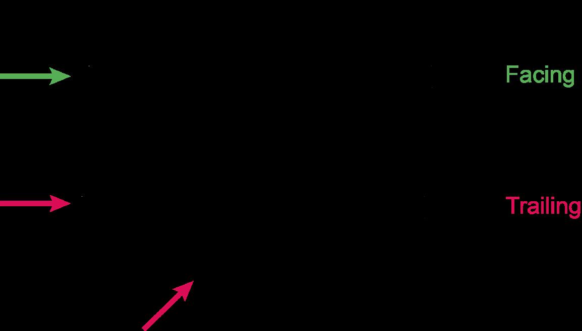
Points are used to enable trains to diverge from the ‘straight’ route ahead, onto another line, or to stay on the straight route. When trains traverse a set of points in this manner, they are said to be travelling over the points in the ‘facing’ direction. Points can also be used in the opposite direction, of course, where two lines converge and become one. Trains using points in this manner are said to be travelling over them in the ‘trailing’ direction – see Figure 2. Many points are used for both facing and trailing movements.
THE BASIC DESIGN OF POINTS
Before going much further, it is necessary to understand the principal parts of a set of points. The main components are shown in Figure 3. Again, terminology varies somewhat, both from one country to another and between the disciplines of permanent way engineering and signal engineering.
Various terms are also used to describe the position of points. In Britain, and in some other countries, when the points are set for straight route they are said to be in the ‘normal’ position, and when they are set for the diverging route, they are in the ‘reverse’ position. This terminology dates from the days of mechanical lever signal boxes, when a lever was said to be in its normal position when it had not been pulled, and in its reverse position when it had been pulled. Alternative terminologies for normal and reverse, which are used in other parts of the world, include left/right, positive/negative and direct/diverted.
The key components of the points shown in Figure 3 are:
• Switch rails (also known as blades or tongues) are the movable rail sections which guide the train along the straight or the diverging route. They are tapered at their tips so as to fit closely to the adjacent stock rail.
Figure 1: Profile of wheels on a pair of rails, illustrating the flanges.
• Stock rails are the outer running rails for the straight and diverging routes. The tips of the switch rails move up tight against the stock rails when in the closed position for the route set.

12
AUTHOR: Francis How, with contributions from John Alexander and Trevor Bradbeer
Figure 2: Facing and trailing directions of movement over a set of points.
• Common crossing, (also known as a ‘Frog’ or ‘Vee’ crossing), is the part of the track layout where the paths of the wheel flanges converge. Of necessity, there is a gap in the rails here so that the wheel flanges can pass through. The existence of a gap can however create problems, particularly on long turnouts, and this subject will be explored further in Part 2.
• Closure rails, (also sometimes referred to as ‘lead rails’ or ‘belly rails’), are non-moving sections of rail that connect the switch rails with the common crossing.
• Cover check rails. These are short sections of rail positioned alongside the stock rail to ensure that the wheels follow the correct route through the common crossing (frog). , (ie they ‘cover’ the gap in the crossing). It can be seen in Figure 3 that there are similar rails alongside and forming part of the common crossing. These are known as wing rails, and sometimes these are manufactured as part of the common crossing rather than being separate rails.
• Stretcher bars are provided at intervals between the two switch rails to help ensure that the correct distance is maintained between them, not just at the tips but throughout their length. Note that railways in many countries do not use stretcher bars, although they are used in Britain and some other countries whose railways are based on British practice. Where they are provided, the number of stretcher bars is governed by the length of the switch rails, which in turn is determined by the maximum permitted speed of trains taking the diverging route.
• Switch heels are the demarcation point between the movable switch rails and the fixed closure rails. A heel block assembly is normally positioned in the vicinity of each heel to maintain the switch, closure and adjacent stock rail in the correct relative positions, although some modern configurations do not require this.
All these components work together to guide a train along the correct route. Ensuring that a train can traverse points safely and smoothly, with minimum wear and tear on both the wheels and the track, means that the design of points is a complex matter, particularly where points are very long (for high-speed turnouts).
What Figure 3 does not depict, but which can be seen in Figure 4, are the supporting elements for the rails. These include extralong sleepers which support the rails. Sleepers are known in some parts of the world as bearers, ties or cross ties. Where ‘flat-bottom’ rails are used they sit on ‘baseplates’; similarly ‘bullhead’ rails sit on ‘chairs’. Note that some types of modern points utilise concrete bearers which do not require either baseplates or chairs for the ‘fixed’ (ie non-moving) rails. (Similar configurations are used also used to support rails in plain line). Where the switch rails move, the baseplates or chairs support both the stock rail and the switch rail. These are ‘slide chairs’, and as well as holding the stock rail in position they also have a flat surface over which the switch rails move laterally. To aid movement, these surfaces are usually
lubricated, or fitted with special inserts to reduce friction, or with rollers which lift the switch rails very slightly while they move.
OPERATIONAL HAZARDS ASSOCIATED WITH POINTS
Thus far, the methods for moving points and holding them in position for the passage of a train has not been described, but this is where the signal engineering discipline applies. Firstly, however, the operational hazards associated with a set of points should be considered. Clearly, a section of rail that can move is potentially disastrous for a train, and the principal hazards are as follows:
1. Points not fully in correct position for the safe movement of a train. For facing movements, this is likely to result in derailment. For trailing movements derailment is unlikely, but damage may occur to the points or associated trackside equipment
2. Points in the opposite position to that required for safe movement of a train. For facing movements, this will result in the train going on the wrong route, which may have consequences such as derailment as a result of excessive speed, or collision with another train. For trailing movements, the train might derail or, more likely, severe damage is caused to the points and the associated trackside equipment.
3. Points moving as a train passes over them. For facing moves, this is very likely to result in derailment of all or part of the train. For trailing movements, it could result in derailment but is more likely to cause damage to the points and associated trackside equipment.
4. Excessive speed. This may result in derailment. Most points have, by their very nature, one position which involves a relatively tight radius curve, corresponding to the diverging route. There is generally no super-elevation or ‘cant’ on the diverging route through the points to help the train negotiate the curve, (unlike plain line curved track).
5. Track gauge is incorrect for safe movement of a train. This is likely to result in derailment. The fact that part of the track is moveable means that there is a somewhat greater risk, (compared with plain line), of the track becoming ‘wide to gauge’ because of lateral outward movement of the rails caused by the passage of successive vehicles or trains.
6. Broken and worn rails. This may result in derailment. The switch blades and the common crossing have less metal to support the wheels, and both the switch tips and the crossing receive more impact from the wheels, which may cause rails to break. Switch and stock rails also wear through use, especially where heavy traffic uses the diverging route. Excessive wear can lead to derailment.
7. The risks associated with the first three of these hazards are controlled principally through the signalling system, of which more information follows shortly.
13
Figure 3: The principal parts of a typical set of points.
Extended sleepers (bearers)
Figure
Stock rail Switch rail
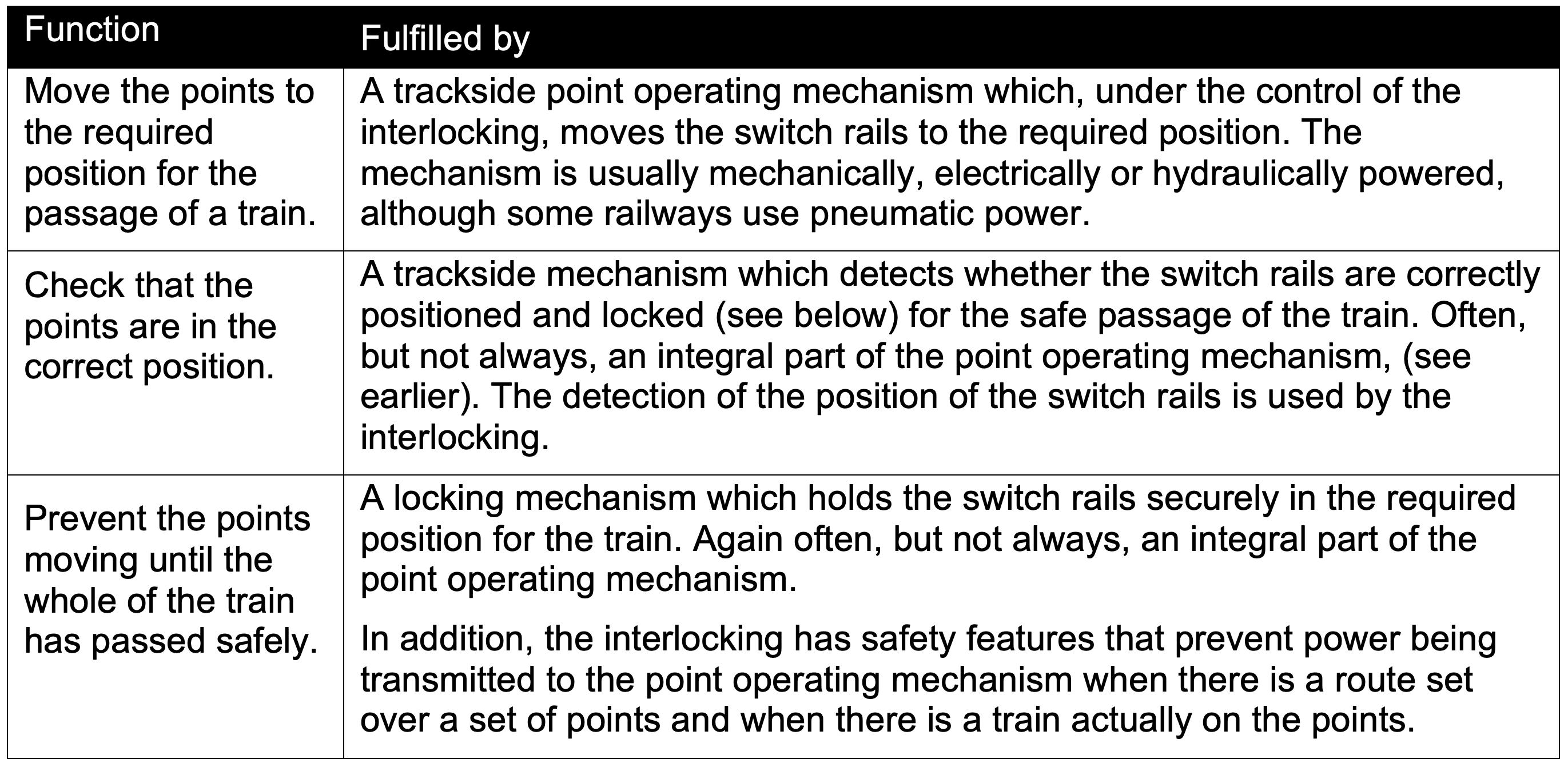
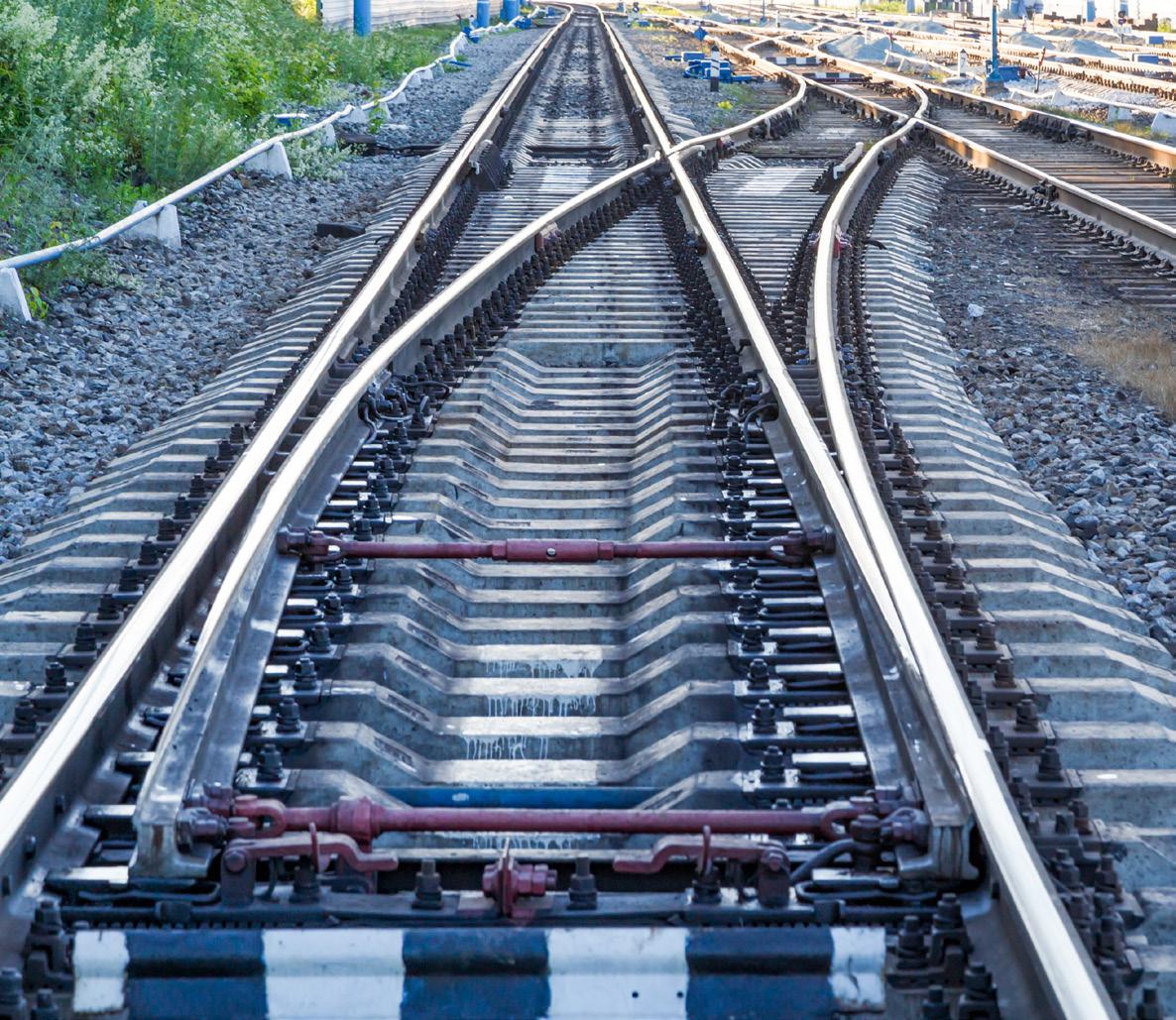
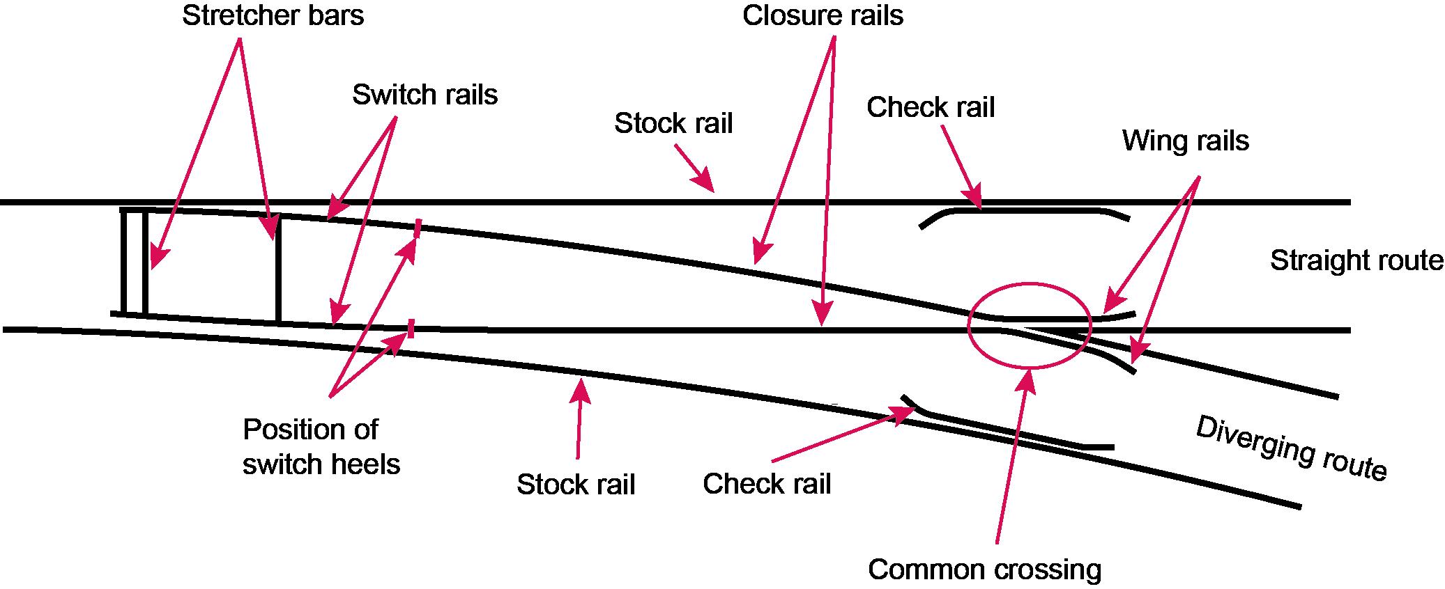
Table 1: The main signalling functions associated with a set of points.
Switch rail Stretcher bar Slide chairs Stock rail
4: General layout of a set of points. (Image: Shutterstock / Timofeev Vladimir).
14
The fourth hazard is usually controlled by a speed restriction that applies to trains taking the diverging route, reinforced by controls in the signalling system. These controls may include route and/or speed indications and aspect controls that instruct/remind the driver to slow down, and train protection systems which enforce speed reduction in the event of driver error.
The risks relating to the fifth and sixth hazards are controlled principally through track inspection and maintenance.
THE ROLE OF SIGNALLING IN POINT OPERATION
The role of signalling in the operation of points is to fulfil three basic functions, and they are achieved jointly by the interlocking and the trackside equipment, as described in Table 1.
The interlocking features relating to points were described in two previous ‘Back to basics’ articles (IRSE News, April and May 2020), and it is not the intention to repeat them in this article. This article focuses instead on the trackside signalling equipment that moves, locks and checks the points.
POINT OPERATING MECHANISMS
MANUALLY OPERATED POINTS
When railways first began, the practice was for railway personnel to operate a set of points using a lever beside the track. Examples of this can still be found in sidings. When signal boxes began to appear, the points were operated by moving a mechanical lever in the box. Each point lever was connected via rodding, (or sometimes wires), and cranks to the tips of the switch rails of the associated set of points, (see Figures 5 and 6).
By pulling the lever to the reverse position in the lever frame, the rodding moved in one direction sufficiently to move the points into the reverse position. Restoring the lever to the normal position returned the points to the normal position.
Because of the weight and the effort required to move the rodding and points via the points lever, the distance from a signal box to a mechanically worked set of points is quite limited (typically ~200-300 metres).
Figure 6: Close-up of a rodding run for several sets of points (a wire run for signals is on the left). (Image: Ian J Allison).
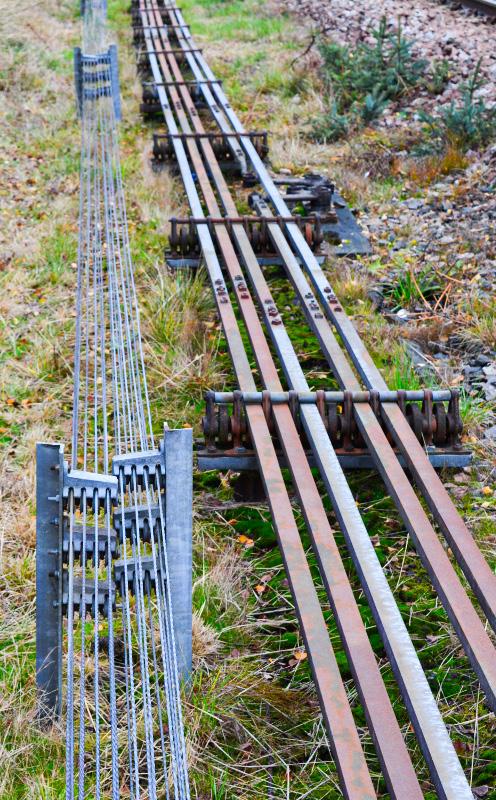 Figure 5: Points rodding leading from the signal box, (out of picture, to the right) to a set of points, with cranks that are used to transmit the motion of the rods through a right-angle. (Image: John Francis).
15
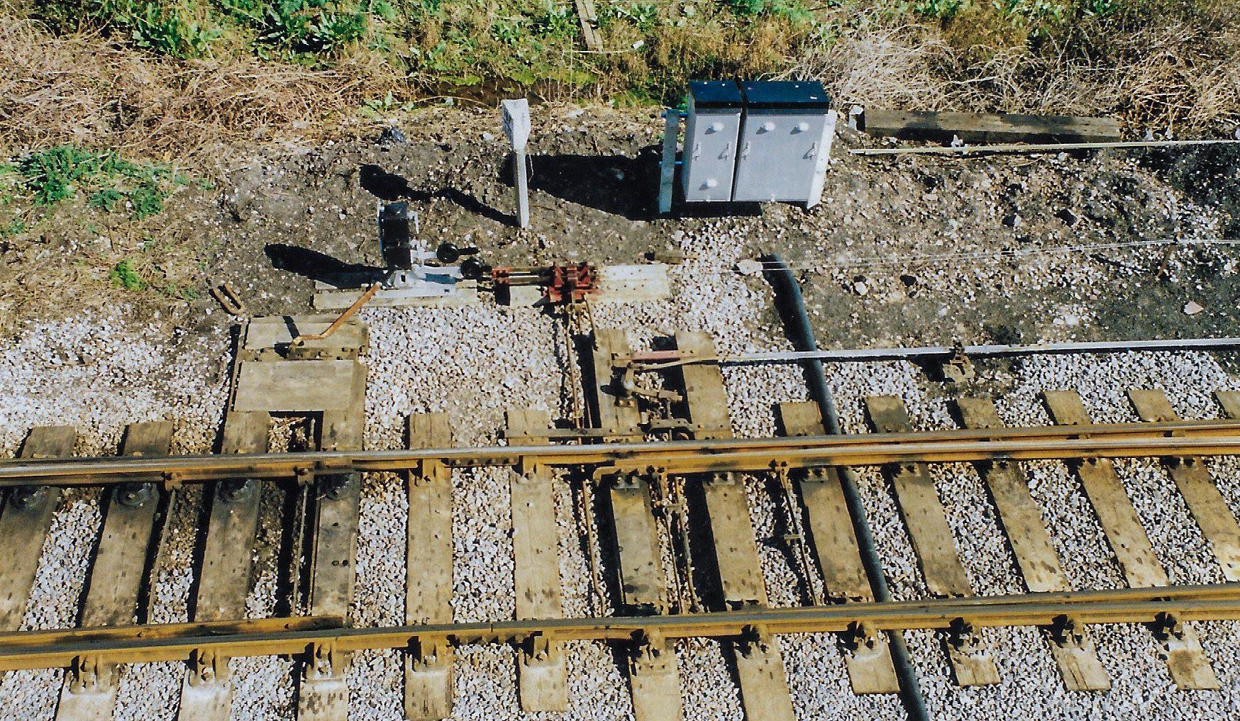
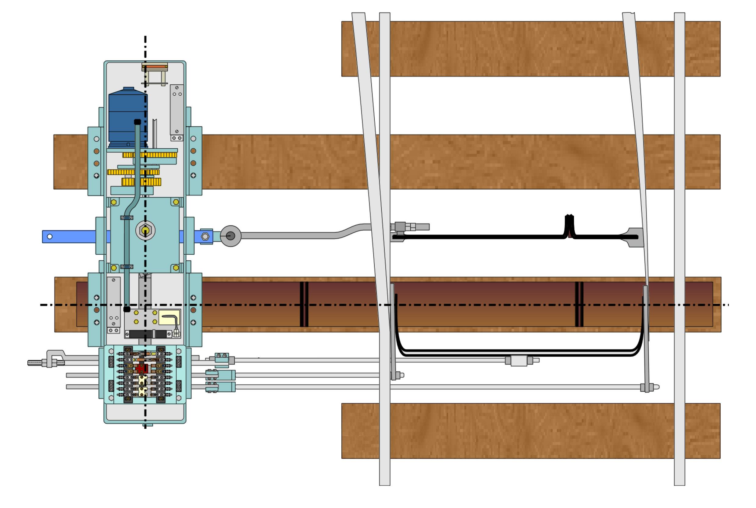
Examples of mechanically-worked points can still be found in many parts of the world, but all modern signalling systems use poweroperated points. Most commonly this takes the form of an electric motor in what is known as a point machine, (also known as a switch machine or switch motor). The point machine is located adjacent to the switch blades and is connected to the tips of the blades either by two rods, (one for each blade), or by a single rod and a bar which links the two tips, ensuring they move in synchronism. The bar is commonly known as a ‘lock stretcher bar’. Figure 7 shows a point machine, with the drive rod connecting the electric motor via gears to the blades. As the motor turns, the rod moves to the left or the right, moving the points to the normal or reverse position respectively. Note that there are other rods also shown in the diagram, the purpose of which will be discussed shortly.
There are many types of point machine in use, with various drive arrangements linking the motor to the switch rails. That shown in Figure 7 is just one example. A layout in a training environment is shown in Figure 8, where the point machine is mounted on extended sleepers (bearers), and as with mechanical points a soleplate, (extended stock rail gauge tie), maintains the gauge and the distance between the track and the point machine.
Over the years, alternative types of powered point operating mechanisms have been produced. Some use hydraulic actuation, such as the clamp lock, (other similar devices are known as chair locks, claw locks and ground locks). The clamp lock has a hydraulic power pack instead of an electric motor, with hydraulic rams, (jacks), positioned between the sleepers to drive the switch rails to the normal and reverse positions.
A further variant is the ‘in sleeper’, (also known as ‘in bearer’), mechanism, where all the machinery is contained within a box or trough which takes the place of a conventional sleeper. This means there is little or no equipment above sleeper level, thus making it easier to undertake mechanised track maintenance without risk of damage to the equipment.
It is also worth mentioning an example of an innovative approach to point operation which has featured in IRSE News, (most recently in May 2019). “Repoint” was a project undertaken by the University of Loughborough (UK) to consider afresh the failure modes of points and to develop an operating mechanism that was more reliable, just as safe, and would help improve track capacity. It illustrates that innovative thinking still has something to contribute to an issue as basic as point operation.
CHECKING THAT POINTS ARE CORRECTLY POSITIONED
The second signalling function associated with points, (listed in Table 1), is to detect the position of the points. This is necessary because it cannot be assumed that the points will move to the position to which they have been called. Ballast or other debris could obstruct the movement, for instance, preventing the switch rail closing against the stock rail. A power failure or malfunction of the point operating mechanism could also prevent the movement. In the situation where the points do not need to be moved for the route being set, it cannot be assumed they are still safely in the correct position for the next train. The passage of the previous trains might have caused the points to open very slightly, through vibration, wear or mechanical failure for instance. It is therefore necessary to check (and report), that the points are correctly positioned. This process is known as ‘detection’.
HOW DETECTION WORKS
The positions of both switch rails are detected, firstly to be sure that the tip of the closed switch rail is sufficiently close to the stock rail that a wheel flange could not pass between the two rails; and secondly to be sure that the gap between the stock rail and the open switch rail is sufficient for the wheel flanges to pass through.
In the case of point machines, detection is achieved using rods that are attached to the tips of the switch blades, which operate electrical contacts in a detector box adjacent to the track as the switches move left or right. In many point machines, the electrical contacts are inside the point machine rather than being a separate unit – see Figure 7: Typical point machine with its connections to the switch rails, (schematic only; not intended to be an accurate representation). (Image: Trevor Bradbeer).
POWER OPERATED POINTS
Detector
Circuit controller and detection contacts Drive rod Stretcher bar Extended sleepers Sole plate Lock stretcher bar Detector rod (right hand switch) 16
Point machine Facing point lock rod
rod (left hand switch)
Figures 7 and 8. These are called ‘combined’ point machines. In the case of hydraulic clamp locks, the contacts are in boxes attached to the outsides of the stock rails.
The electrical contacts for both switch rails are combined into points detection circuits, the outputs of which are fed back to the interlocking via fail-safe relay circuits or a high integrity transmission system. Hence the interlocking knows whether the points are normal, reverse or in an indeterminate state, (neither normal nor reverse).
Where points are worked mechanically via rodding, a wholly mechanical detection system is often used. The detection rods are connected to sliding metal plates which engage with similar slotted plates at right angles which are connected to the wires that operate the mechanical signals. This ensures that the wires leading to the signals cannot be operated unless the points are correctly set, and vice versa. Hence there is direct interlocking of points and signals at the trackside, in addition to the interlocking of the levers in the signal box. An example of such a device is shown near the top left of Figure 5.
DETECTION TOLERANCES
The permissible gaps between the switch and stock rails vary slightly from country to country, but on a standard gauge railway the gap on the closed switch rail side must typically be no more than ~5mm, and on the open switch rail side it must be at least ~115mm, (these figures may also vary depending upon the type of points and operating mechanisms). If these criteria are not satisfied, the detection circuits will indicate to the interlocking that the points are not correctly positioned. Tolerances are generally assigned to these values, both to allow some latitude when setting up or maintaining the points and to reduce the risk of the closed switch detection being intermittently lost due to track vibration or slight movement. Thus, for instance, one railway administration states that the closed switch detection contacts must just be made at a switch-stock rail gap of 4mm (but not less) and definitely broken at 6mm.
Detection of the open switch may at first sight appear to be less critical than the closed switch, but there have been accidents such as at Kingham (1966) and Grayrigg (2007) , both in Britain, where the open switch rail gap was insufficient. The continual battering by the backs of wheels caused the open switch rail and fittings to be fatigued, causing fractures leading to derailment. The condition of the stretcher bars was implicated in both accidents.
LOCKING THE POINTS IN POSITION
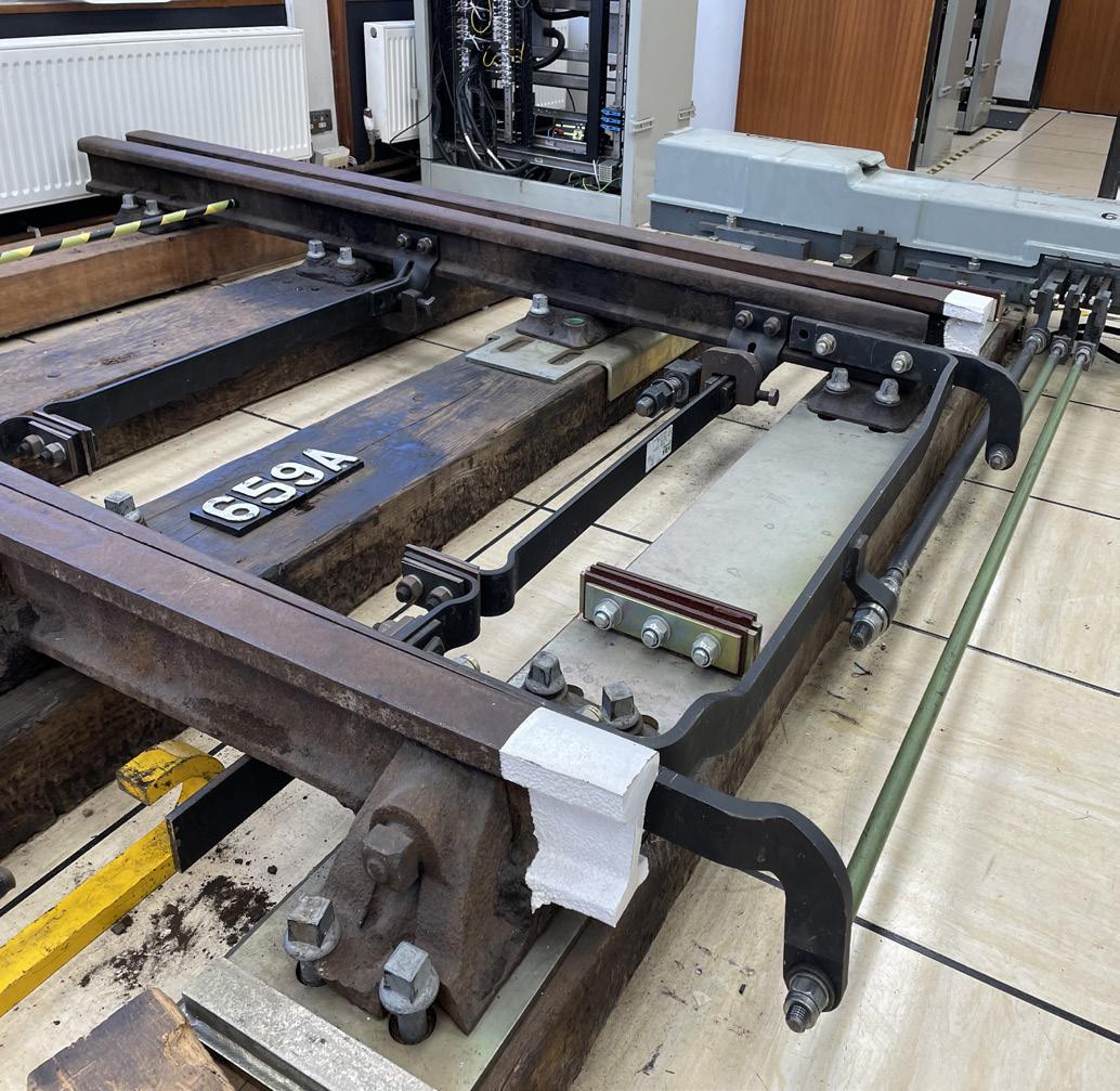
Figure 8: A typical point machine arrangement (in a training school environment) showing the drive rod, detection, FPL rodding connections, and associated stretcher bars. (Image: Trevor Bradbeer and Signet Solutions).
The third and final signalling component of points operation is the physical locking of the points in the required position, to minimise the risk of the switch rails moving. The locking mechanism is known as a ‘point lock’ or ‘Facing Point Lock’ (FPL).
17
Figure 9: A facing point lock on a set of mechanical points. (Image: Trevor Bradbeer).
WHY ARE POINTS LOCKED?
In Britain it has been, from relatively early railway days, a legal requirement that points used by passenger trains in the facing direction are fitted with a lock. The Board of Trade’s 1892 requirements relating to the opening of new railways stated that “In order to ensure that the points are in their proper position before the signals are lowered, and, to prevent the signalman from shifting them, while a train is passing over them, all facing points must be fitted with facing-point locks…”.
This leads to two key observations. Firstly, the requirement recognised that points traversed in a facing direction present a much greater hazard than in the trailing direction; and secondly, the hazard was originally perceived more in relation to signalman error than the points having an excessive gap between the closed switch and stock rail because of poor adjustment, track movement or wear and tear. The risk of signaller error in relation to points movement has now all but disappeared as a consequence of comprehensive interlocking of points, tracks and signals. However, the requirement to lock facing points on passenger lines remains in most countries in the world and serves to minimise the risk of derailment in the vicinity of the blade tips. Furthermore, in practice many railways lock the points for movements in the trailing direction as well as facing, and also lock points on freight-only lines.
The extreme dangers associated with facing points can be seen throughout the history of railways. As with so many safety features on railways, accidents led to the introduction of facing point locks. In Britain there was for many years an aversion to having facing points at all, something which reached its height in 1873 when a north-bound express train derailed on points at Wigan station. Thirteen people died as a result of the points moving under the train (not, in this case, by the action of the signalman but because of the excessive speed of the train). The accident brought to the fore the need to fit locks to facing points. Even in relatively modern times points-related accidents have still occurred. Examples include Potters Bar, UK (2002), Grayrigg, UK (2007) and South Carolina, USA (2018).
HOW POINTS ARE LOCKED
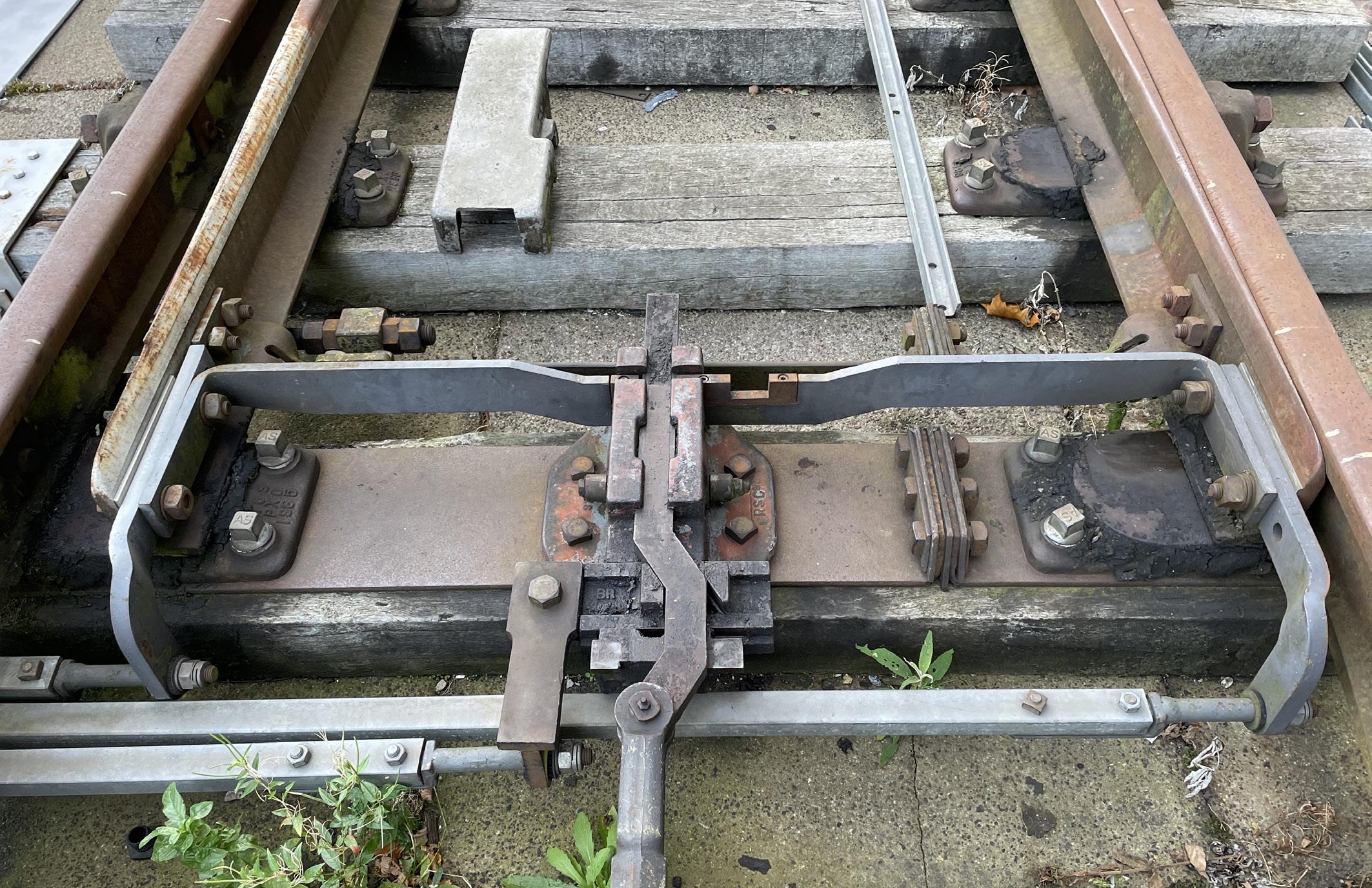
As with detection, the facing point lock mechanism varies in design for mechanically-worked and power-operated points. It is instructive to start by looking at mechanical points – see Figure 9. A lock stretcher bar connects the two switch blades. It has two slots cut into it. When the points are in the required position, the signaller pulls the FPL lever. This is a separate lever, not the same one as is used to move the points. The lever is connected via rodding to the lock rod, driving it into one of the two slots in the lock stretcher bar. There is one slot for the points in the normal position, and a second for the reverse position.
It can be seen that when the lock is engaged in one of the slots, it is impossible for the switch blades to move, either by the signaller attempting to move the points lever or by vibration as a train traverses the points. Figure 9 also shows the metal soleplate, (also known as the stock rail gauge tie), on which the lock and the two slide chairs are rigidly mounted to prevent movement and maintain the correct gauge at the switch tips.
Moving on to power-operated points, although some railways use point locks which are actuated by a mechanism separate from that which moves the points, more commonly the lock is part of the point operating mechanism. In the case of point machines, the lock is usually contained within the machine. It can be seen in Figures 7 and 8 that one of the rods coming out of the point machine is connected to the mid-point of the lock stretcher bar. Inside the point machine the rod is connected to a lock mechanism. As the point machine completes the point movement, (either normal or reverse), it engages the lock mechanism, so preventing the rod, lock stretcher bar and switch blades from moving until the point machine is powered up again to move the points to the other position.
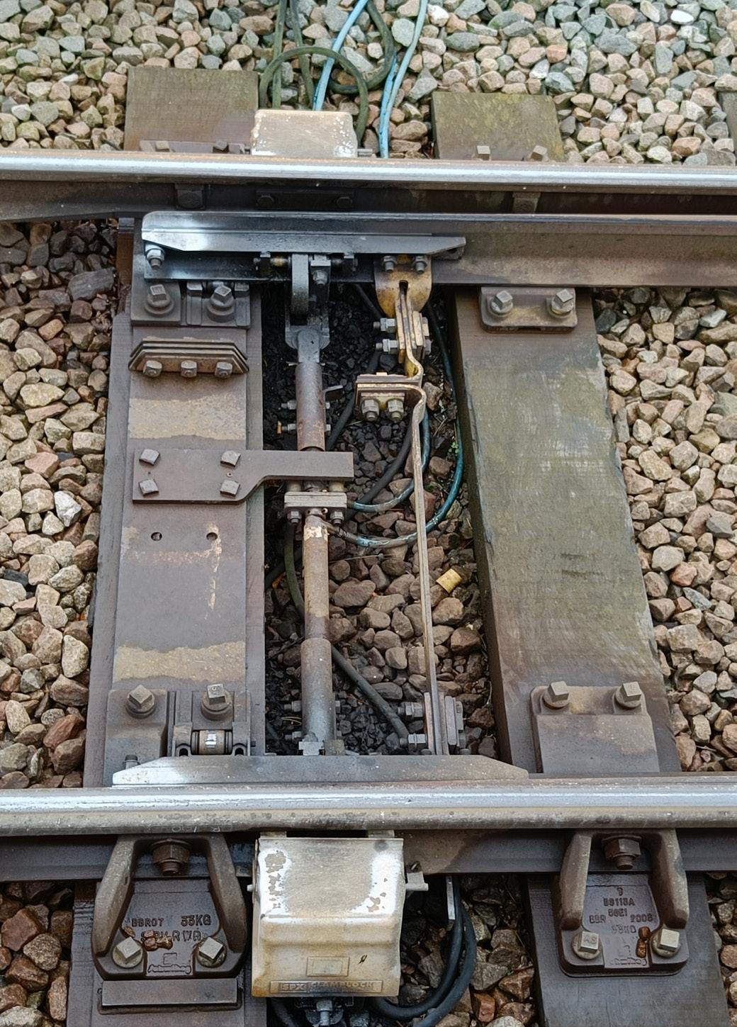
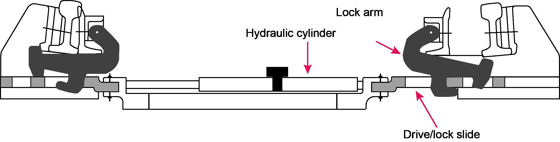
In the case of a clamp lock, the locking mechanism is different, although its purpose is the same. It is not simple to explain how a clamp lock works – it is easier to understand by seeing one in action. In essence, there is a G-shaped lock arm, (sometimes called a claw), attached by a pivot to the inside of each switch rail. The hydraulic rams move the switch rails via the drive/lock slides and the lock arms, and eventually the free end of the lock arm on the closed switch side is forced up so that it fits tightly against the outside of the stock rail. The switch and stock rails are thus physically clamped to each other and cannot be moved unless the clamp lock is powered to the opposite position – see Figures 10 and 11.
Some point operating mechanisms have a quite different type of lock. For instance, the UK High Performance Switch System (HPSS) utilises a lead screw, (which moves the blades normal and reverse), combined with a brake, thus preventing any movement of the blades when they are in the required position.
In power-operated points, the detection circuits referred to earlier also include electrical contacts to prove that the lock has engaged. Thus, when the detection circuit informs the interlocking that the points are normal or reverse, this information is, in effect confirming that the closed switch is against the stock rail, the other switch is sufficiently open, and the switches are locked in position.
It can be seen from what has been considered so far that modern point machines, clamp locks and similar devices combine the functions of point movement, detection and locking in one trackside device. Taking the example of a conventional point machine, a typical sequence of operations for moving the points from normal to reverse is as follows:
1. Motor starts turning when powered from the interlocking.
2. Point lock disengages by the action of the motor. As soon as this starts to happen the normal detection circuit is forced to break, (even though the switches are still normal at this stage).
3. Switches are driven to the reverse position by the action of the motor.
4. Point lock engages by the action of the motor.
Figure 10: Typical clamp lock installation. (Image: Francis How).
5. Reverse detection circuit is energised, provided the lock has successfully engaged and both switch rails have fully moved to the reverse position.
18
Figure 11: Clamp lock cross section.
6. Power to the motor is switched off by contacts on the circuit controller inside the point machine, (the interlocking also disconnects the power to the points when reverse detection is obtained).
7. The motor is electrically braked by ‘snubbing’ contacts on the circuit controller, (somewhat like regenerative braking), to avoid damage to the motor and mechanical parts when the movement reaches the end of its travel.
Facing point lock tolerances
Although it is desirable from a safety perspective for the gap between the closed switch rail and the stock rail to be as small as possible, (ideally zero), in practice some tolerance must be applied. Without this, the very slightest movement or incorrect adjustment of the points might mean the point lock could not physically engage. If that were to happen, the detection circuits would indicate that the points were not locked, and therefore trains could not be signalled over them. This is a classic example of a points failure, causing delays to trains and requiring a technician to attend the points. The provision of the tolerance is, therefore, a trade-off between safety and reliability.
Accordingly, points are adjusted so that with a very small gap between the switch and stock rail, (typically 1.5mm on standard gauge railways), the lock can still engage. If the gap is much larger, (typically 3.5mm), the lock must fail to engage. The normal way of checking these gaps is to use a facing point lock gauge. This is nothing more than a small rectangular piece of metal, 1.5mm thick at one end and 3.5mm thick at the other. Each end is in turn inserted between the stock and switch rails, and the points moved, (generally by hand operation rather than under power), to check that at 1.5 mm the lock engages and that at 3.5mm it does not. The tolerances may vary slightly for different railways and countries, but the principles are the same.
STILL TO COME…
This article has explored the basics of points and point operation, and the role of signalling and the signal engineer in ensuring they work safely. In Part 2 some of the additional features and functions associated with points will be looked at, including topics such as trailable points, catch points, turnouts on high-speed railways, and more.
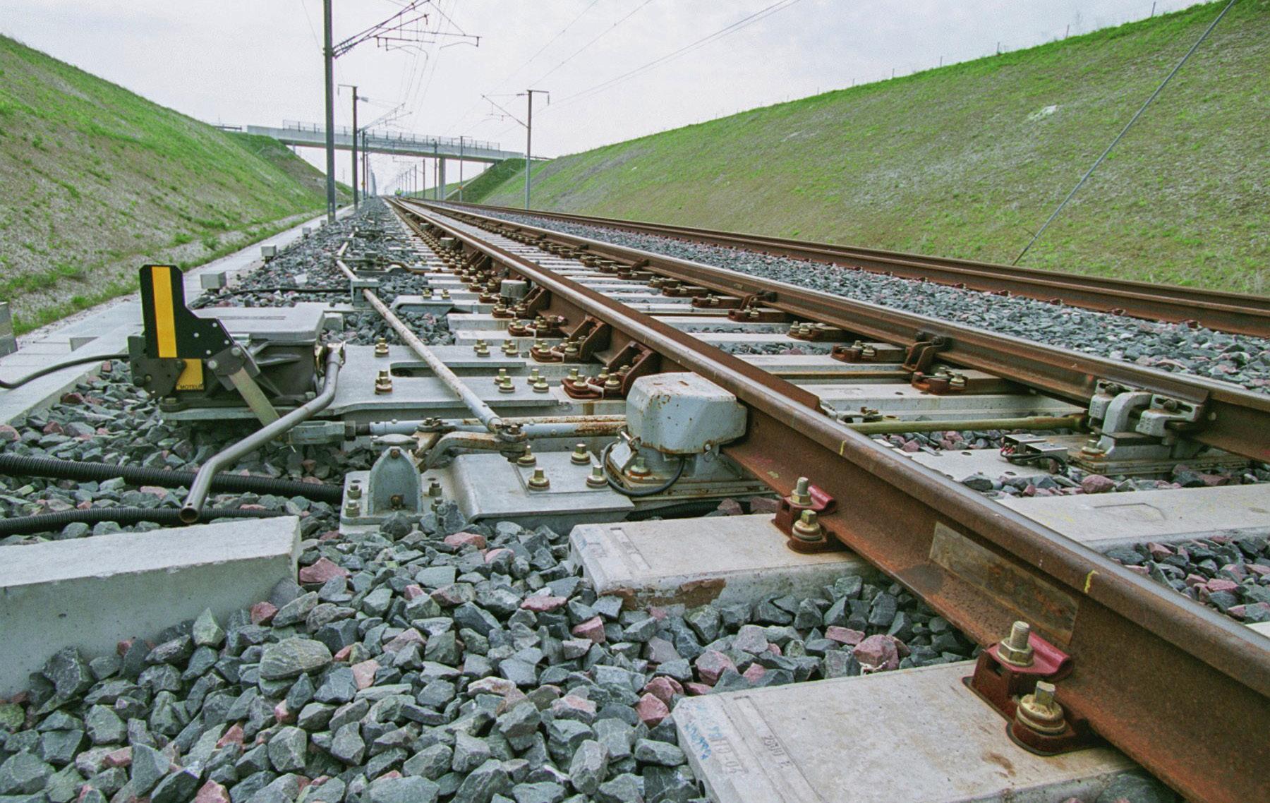 Figure 12: A high speed turnout on the Paris to Strasbourg High Speed Line. (Image: SNCF).
19
Advances in engineering survey grid transformations for rail infrastructure
The HS2 Learning Legacy website was launched at an industry event in October 2021, and builds on the experience from the learning legacies of previous major projects. These include the Crossrail Learning Legacy, Thameslink Learning Legacy and the London 2012 Learning Legacy, and it contributes to an overall body of knowledge on major projects captured on the Major Projects Knowledge Hub.

It aims to capture and disseminate good practice, innovation and lessons learned from HS2 aimed at raising the bar in industry, improving UK productivity and showcasing UK PLC. HS2 is keen to engage with industry bodies and professional associations to work together to further disseminate the Learning Legacy following the launch, and part of this work is the publishing of a number of the HS2 Learning Legacy papers in the PWI Journal.
AUTHORS:
James Turner - HS2 Ltd
Chris Preston - HS2 Ltd/CP Geospatial Services Ltd
Richard Winthrop - HS2 Ltd/Sailine Ltd
Ian Thatcher - HS2 Ltd/Atkins
Peter Swales - HS2 Ltd/CADBadger Ltd
Jamie Finney - HS2 Ltd
This paper provides a summary of innovative approaches developed on Snake Projection coordinate transformations that maximise data interoperability and compatibility within CAD, GIS and survey software and systems.
The project’s topographical survey, design and construction use an engineering coordinate system defined by the HS2 Snake Projection together with the HS2 Vertical Reference Frame. This approach has several advantages including minimal scale factor and height distortion at track level [1] with seamless continuity over the project.
For HS2, the zero-order survey control is defined by the Ordnance Survey OS Net™ network of Continually Operating GNSS Reference Stations (CORS). In 2016, Ordnance Survey updated the geodetic coordinates of OS Net [2] and the implications of these changes on HS2’s track design are potentially significant. For example, the update caused a 13mm horizontal shift and 25-30mm vertical shift in engineering coordinates. To ensure the project achieves positional stability and thus remains unaffected by these changes, both now and into the future, a description is presented of the development of a new geodetic transformation called HS2TN15 and a new equipotential geoid model, HS2GM15, which are applicable respectively to plan and height coordinates.
The HS2 Survey Grid transformations enable highest accuracy engineering survey for the project design, construction and operation; fully validated and authoritative for use, with significant benefits realised to date. HS2 has led knowledge sharing sessions with the wider industry, with the revised Snake Projection methodology being increasingly adopted on further infrastructure projects.
BACKGROUND
One of the fundamental issues of survey engineering is how best to represent the curved surface of the Earth onto a flat plane without introducing distortion of some kind. An example is illustrated in Figure 1, where the scale factor represents the errors in distance measurements within the projected grid. The Snake Projection solves this. It is a relatively new innovation in planar engineering grids that was developed through a collaboration between Network Rail and University College London [3]. When tailored to a specific project the Snake Projection delivers a seamless coordinate system. It is typically used on long linear infrastructure works, and effectively operates as a true-scale site grid that is valid for the entire length of the route.
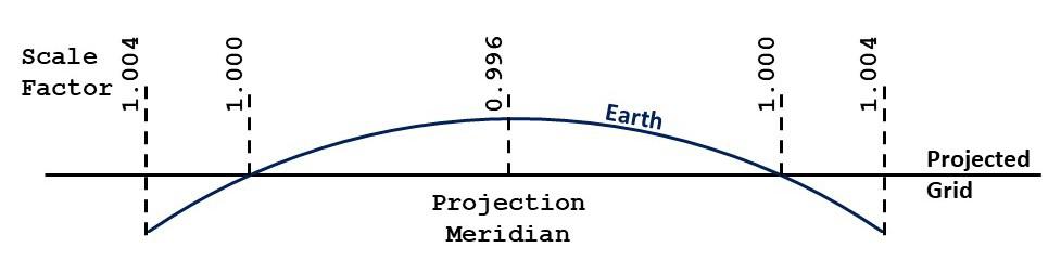
The HS2 Snake Projection applies to both Phase One between London and the West Midlands and Phase 2a to Crewe. It features scale factor distortion of under 20 PPM throughout, which equates to a distance distortion less than 2cm per km (a map of distortion at ground level is seen in Figure 2).
To demonstrate the reasons for using the HS2 Snake Projection, imagine a line approximating the route from London to Birmingham. Measuring the line first in British National Grid, and then measuring again in HS2 Snake Projection would reveal an apparent increase in length of 60 metres. In fact, the length of the project on the ground did not change it is just that the British National Grid is a best-fit for the whole country which means the map distortion is far in excess of what is appropriate for precision engineering required on projects like HS2. Consequently, the HS2 Snake Projection is the horizontal coordinate system used for project design and construction.
20
Figure 1: The basic issue solved by the Snake Projection: projecting the curved surface of the earth onto a flat plane.
In the vertical dimension, engineering levels have been measured with respect to Ordnance Datum Newlyn (ODN), the national height reference. Together with Eastings and Northings in the HS2 Snake Projection, project engineers use a compound coordinate system commonly termed HS2 Survey Grid.
THE HS2 SNAKE PROJECTION – A REVISED IMPLEMENTATION
Since the development of the Snake Projection methodology, the advantages have been readily apparent to the extent that it is now being used throughout the UK rail industry. The fundamental task of its algorithm is to convert between geodetic coordinates and grid coordinates. However, the projection algorithms and parameters are so new as to be unsupported by the majority of spatially enabled software and systems, including CAD and GIS. Furthermore, the methodology was not viable for inclusion in the European Petroleum Survey Group global coordinate system registry [4], which is the authoritative source of geodetic definitions used by AEC software providers.
The situation mirrors a similar scenario faced several years ago by Ordnance Survey when it was defining the British National Grid using the OSTN02 transformation [5]. The native ‘Grid Inquest’ OSTN02 was not directly compatible with a variety of software packages therefore it was released in a second format, this time using a standard grid shift file for geodetic transformations called ‘National Transformation version 2’ (NTv2; [6]).
Inspired by Ordnance Survey’s approach, HS2 Ltd conducted a proof-of-concept study to research and validate an alternative implementation for the HS2 Snake Projection which was based upon existing standards. This emulation of the authoritative methodology was implemented by the creation of a new Transverse Mercator projection (HS2-TM) and intermediate reference frame (HS2-IRF) accompanied by a new NTv2 transformation comprising a grid of shift values to transform between ETRS89 and the HS2-IRF (see Table 1).
The study was a success the HS2 NTv2 process was verified via desktop study at over 348,000 locations project-wide and featured virtually identical agreement with the authoritative Snake Projection method (RMS difference was negligible at 0.2mm).
SINGLE SOURCE OF TRUTH
The impact of the HS2 NTv2 revision was significant. The coordinate system became immediately compatible with virtually all spatially enabled platforms, in particular CAD and GIS. The first benefit was allowing the reprojection of design data to and from the HS2 grid to be undertaken in-situ, which is especially useful for CAD files which will now retain complex geometry.

Perhaps the most significant benefit is the use of reprojection ‘on the fly’ which facilitates the single source of truth. Previously the same piece of geospatial information may have been stored in multiple data containers; one for each of the coordinate systems required, which resulted in significant issues with data conversion and data management. Now a single version of data requires maintenance, and when the geometrical representation is required in an alternate coordinate system the reprojection can be performed automatically within software.

HS2 has undertaken a study with TfL to investigate the benefits of data coordination using the ‘on the fly’ reprojection method that is now available. On the back of this study HS2 and TfL agreed a concession against the requirement to deliver data for coordination and at handover to TfL in their LSG grid. Benefits to the project included:
RISK REDUCTION – removing the requirement of translating AEC data between HS2 Snake Projection and TfL LSG grid resulted in minimisation of the risk from added translation inaccuracies. The new process also removes risk due to data recipients no longer having to take ownership of data through their translation process.
DESIGN COORDINATION – the coordination between HS2 and TfL is smooth and immediate without the need to translate the data each time information is issued.
RESOURCES – by adopting a streamlined process there is scope for efficiency savings by removing the requirement of coordinating with TfL standards and grids as well as with HS2 standards and grids. Over the life of the project, resultant cost savings have the potential to be significant.
As demonstrated, the tangible benefits for data currency, data management and efficiency are significant. HS2 are now working with other interfaces to realise the same benefits as with TFL, to again reduce risk and cost.
CORS OS NET UPDATE 2016
In Great Britain, Ordnance Survey operates OS Net – a CORS network of stations that operate as the national reference for Global Navigation Satellite Systems (GNSS) survey. In 2016 the geodetic ETRS89 coordinates of the stations were recomputed from OS Net v2001 to OS Net v2009 causing a horizontal shift in coordinates [2]. To minimise the impact on National Grid coordinates Ordnance Survey released a new transformation, OSTN15. As a result, National Grid coordinates are achieved through OS Net v2009 + OSTN15, with the aim of equivalence to those achieved through OS Net v2001 + OSTN02.
Figure 2: Distance distortion in the HS2 Survey Grid at ground level.
At the same time Ordnance Survey released an updated geoid model (or more correctly a “height corrector surface” since a gravimetric geoid surface has been fitted to the local mean sea level based datums) for use with the revised OS Net. OSGM15 transforms ellipsoidal heights into orthometric levels above Ordnance Datum Newlyn (ODN). In this case the updated transformation did not achieve equivalence, with a 25mm step in measured levels compared to those achieved before the 2016 update with OSGM02. Effectively the datum point for height measurement was systematically lowered, resulting in ODN heights increasing by approximately 25mm nationwide. Table 1: The HS2 Snake Projection NTv2 definition. 21
The underlying datum for the HS2 Snake Projection is the same as for the British National Grid: ETRS89 as realised by the OS Net CORS network. Consequently, HS2 engineering coordinates were subject to the same horizontal shift when the OS Net was recomputed in 2016. For an engineering coordinate system implemented for precision and accuracy this is not insignificant and has the potential to introduce spatial misalignment exceeding accuracy tolerances for construction of the permanent way.

In this situation the Ordnance Survey approach was the inspiration once more. Following the OS transformation naming convention, the legacy process for determining HS2 coordinates became known as HS2TN02. The revised implementation of the HS2 Snake Projection suddenly acquired a further benefit because the flexibility of the NTv2 format enabled HS2 to effectively maintain positional stability of grid coordinates. This was accomplished by the computation of a new geodetic transformation, HS2TN15, valid for acquiring HS2 grid coordinates using the updated version of the OS Net.
Now, HS2 Snake Projection coordinates achieved through OS Net v2009 + HS2TN15 are virtually equivalent to those achieved through OS Net v2001 + HS2TN02. Thus, the project risk from geodetic change is reduced.
ORTHOMETRIC HEIGHT
In the vertical dimension, HS2 engineering data uses levels referenced to the national height reference Ordnance Datum Newlyn. However, as described above, in 2016 the datum itself was redefined resulting in a vertical shift of approximately 25mm. In effect, the significant majority of existing survey and design data across the HS2 Project became referenced to a legacy vertical datum.
To prevent ambiguity in the management of engineering data the need for a standardised approach was evident; this would have to be the best available in terms of survey accuracy, consistency with existing data and immunity from any future changes.
The solution was to create the HS2 Vertical Reference Frame (HS2VRF) with the aim being all existing and future project engineering data is on the same height system. To ensure existing data retains currency the HS2VRF is defined to be equivalent to the legacy Ordnance Datum Newlyn realisation 2002.
HS2 HORIZONTAL TRANSFORMATIONS – HS2TN02 AND HS2TN15
Figure 3: HS2GM15 Height Surface Correction values. 22
However, in order to retain full survey accuracy there must be a defined relationship to the contemporary OS Net. This necessitated the computation of a new national height corrector surface called the HS2 Geoid Model 2015 (HS2GM15).
DEVELOPMENT OF HS2GM15
The purpose of the HS2 Geoid Model 2015 is to provide a geodetic transformation such that a GNSS survey conducted using the contemporary OS Net (v2009) can recreate the same ODN levels as if surveying using the previous OS Net (v2001) along with the previous OS geoid model (OSGM02).
The set of control points used for the development of the HS2 Geoid Model 2015 was the 100 Ordnance Survey CORS stations which have geodetic coordinates and orthometric heights available for both OS Net v2001 and OS Net v2009. Using the OSGM02 model as the base surface a correction value could be calculated at each control station, which can be simplified as:
(1)
Where is the difference between the ellipsoidal height of station p in OS Net v2009 and the previous orthometric height of station p in ODN02.
is the OSGM02 datum height at station p.
Least squares collocation is a standard method for interpolating corrections across an equipotential surface [7]. Note that this method accounts for spatial correlation and measurement noise, to produce an optimal solution that does not guarantee ties to control points.
To derive the surface correction value u for location i the closest 5 CORS control stations are used in a least squares collocation process:
(2)
Where
u p is the vector of corrections at CORS locations (corrp),


Cip is the vector of covariances between interpolation location i and CORS control point p, and
C pp is the matrix of covariances between CORS control points.

In total across the area of interest there are 2,196,661 correction values computed with minimum value -0.04m and maximum value +0.06m; these are plotted in Figure 3. The HS2 Geoid Model 2015 was then able to be calculated by summing the OSGM02 geoid heights with the collocated correction values.
VALIDATION AND VERIFICATION OF THE HS2 GEOID MODEL HS2GM15
The verification process for the HS2VRF was to collate field measurements at a number of locations and process both in legacy (OS Net v2001) and current (OS Net v2009) geodetic datums and transform to HS2VRF orthometric heights using the respective transformation. The overall plan followed:
• Survey GNSS field data (Rinex) at 65 benchmarks (BMs) along the HS2 route.
• Using legacy OS Net CORS – post-process OS Net v2001 geodetic coordinates for each BM.
• Calculate HS2VRF height using OS Net v2001 coordinates and OSGM02 [A].
• Using contemporary OS Net CORS – post-process OS Net v2009 geodetic coordinates for each BM.

• Calculate HS2VRF height using OS Net v2009 coordinates and HS2GM15 [B].
• Validate HS2GM15: Compare height differences between [A] and [B].
The optimal result of the validation process was that the levels achieved through the two methods, [A] and [B], are identical. There were two sets of validation data i.e. the primary set comprised 13 benchmarks that featured a Root Mean Square (RMS) separation in determined levels of 1.3mm, and the 52-strong secondary set featured an RMS separation in levels of 2.5mm.
These differences were deemed minimal, consequently vertical coordinates achieved through OS Net v2009 + HS2GM15 may be said to be virtually equivalent to those achieved through OS Net v2001 + OSGM02.
SUMMARY – THE HS2 TRANSFORMATIONS
The HS2 transformations and the relationship to GNSS-acquired geodetic coordinates are summarised in Figure 4. To highlight the relationship with National Grid coordinates the OS transformations are also included. Note that the HS2P1+14 Snake parameter file is equivalent to use of HS2TN02 and therefore is to be used alongside the legacy CORS network using OS Net v2001.

When utilising GNSS for HS2 engineering positioning use the contemporary OS Net with the respective coordinate transformations to achieve HS2 engineering positions. At the time of writing the current definition is v2009, therefore the HS2TN15 and HS2GM15 transformations are appropriate.
When converting between OS grid and HS2 grid coordinates always use the same transformation versions. For example, use OSTN02↔HS2TN02 or OSTN15↔HS2TN15.
CONCLUSIONS
Three major developments have been described; a new implementation for the Snake Projection which massively increases compatibility, the strategic development of updated transformations for rail engineering grids which follow Ordnance Survey standards, and finally the computation of a new national geoid model to provide consistent levels over the life of the HS2 Project from design to construction and into operation.
All together these provide a basis for coordinate system use, maintenance and stability that is independent of changes to the national control framework and aims to guarantee temporal viability of data holdings as much as possible.
Figure 4: HS2 transformation summary and reprojection guidance.
23
The innovative revisioning of the HS2 Snake Projection to an effective ‘open source’ NTv2 methodology is fully validated and authorised for use. It has massive implications for geospatial data management and manipulation and has provided significant time and efficiency savings to date, including the example quoted. Being equally applicable to further Snake Projections, the development is of great interest within the wider rail and road industry and HS2 Ltd has held knowledge sharing workshops to enable wider exploitation. Projects recently adopting the technology include the Midland Main Line and the upgrade of the A96 from Aberdeen to Inverness.
The current HS2 Snake Projection is valid for Phases One and 2a. Looking to the future, it will be extended to include the grid for Phase 2b to define a single continuous engineering grid featuring unity scale for the whole project that is fully compatible within geospatial systems.
Finally, there is one more positive: through the revised implementation, tailored Snake Projections are now acceptable for inclusion in the global registry of coordinate systems. A whole new wave of EPSG codes is on the way.
ACKNOWLEDGEMENTS
The services of the Natural Environment Research Council (NERC) British Isles continuous GNSS Facility (BIGF), www.bigf.ac.uk, in providing archived GNSS data (and/or products) to this study, are gratefully acknowledged.
REFERENCES
[1] RICS (2020) Map Projection Scale-Factor. Online: https:// communities.rics.org/gf2.ti/f/200194/3631013.1/PDF/-/657_Map_ Proj_Scale_Factor_1st_final_draft.pdf [Accessed 2020-07-07]
[2] M. Greaves, P. Downie & K. Fitzpatrick (2016) OSGM15 and OSTN15: Updated transformations for UK and Ireland. Geomatics World, https://www.ordnancesurvey.co.uk/documents/resources/ updated-transformations-uk-ireland-geoid-model.pdf
[3] J. C. Iliffe, J. V. Arthur & C. Preston (2007) The Snake Projection: A Customised Grid for Rail Projects, Survey Review, 39:304, 90-99, https://doi.org/10.1179/003962607X165041
[4] EPSG (2020) EPSG Geodetic Parameter Registry. Online: http:// www.epsg.org [Accessed 2020-07-07]
[5] Ordnance Survey (2002) OSTN02 – NTv2 format. Online: https:// www.ordnancesurvey.co.uk/business-government/tools-support/osnet/format [Accessed 2020-07-07]
[6] Government of Ontario IT Standards (2005) NTv2 (National Transformation Version 2), Document No. 45.2.
[7] J.C. Iliffe, M. K. Ziebart, & J. F. Turner (2007) A New Methodology for Incorporating Tide Gauge Data in Sea Surface Topography Models, Marine Geodesy, 30:4, 271 – 296, https://doi. org/10.1080/01490410701568384
NOTATION
AEC: Architecture, Engineering and Construction.
BNG: British National Grid. Also known as OS National Grid.
CAD: Computer Aided Design.
CORS: Continually Operating Reference Stations.
EPSG: European Petroleum Survey Group.
ETRS89: European Terrestrial Reference System 1989.
Geoid: An equipotential surface defined as being equivalent to mean sea level without the effect of tides and currents; commonly used as the zero-point for orthometric heights.
GIS: Geographical Information Systems.
GNSS: Global Navigation Satellite Systems.
Height Distortion: The distance between two points increases with elevation, thus introducing a height component into the scale factor distortion.
HS2GM02: HS2 height correction surface for the conversion of ellipsoidal heights derived from GNSS to HS2VRF. HS2GM02 preceded HS2GM15 and is used for data captured using OS Net v2001 only.
HS2GM15: HS2 height correction surface for the conversion of ellipsoidal heights derived from GNSS to HS2VRF. HS2GM15 superseded HS2GM02 and is used for data captured using OS Net v2009 only.
HS2P1+14: The HS2 SnakeGrid™ to be used for engineering design from Euston to Wimboldsley (north of Crewe). The HS2P1+14 parameter file is equivalent to HS2TN02.
HS2TN02: HS2 Survey Grid transformation to convert between ETRS89 (latitude and longitude) OS Net v2001 values and HS2 SnakeGrid. HS2TN02 preceded HS2TN15 and is used for data captured using OS Net v2001 only.
HS2TN15: HS2 Survey Grid transformation to convert between ETRS89 (latitude and longitude) OS Net v2009 values and HS2 SnakeGrid. HS2TN15 superseded HS2TN02 and is used for data captured using OS Net v2009 only.
HS2VRF: HS2 Vertical Reference Frame – HS2 height datum, equivalent to ODN02, realised by use of HS2GM15 with OS Net v2009.
LSG: London Survey Grid.
NTv2: National Transformation version 2.
ODN02: Ordnance Survey Newlyn height datum based on OSGM02. This is the height datum used by HS2.
ODN15: Ordnance Survey Newlyn height datum based on OSGM15 and currently used by the Ordnance Survey. Height values in ODN15 are approximately 25 mm higher than heights in ODN02.
OS: Ordnance Survey.
OS Net: Ordnance survey active network of GNSS base stations providing a realisation of ETRS89. In 2016 base station geodetic coordinates were updated from OS Net v2001 to OS Net v2009 (latitude, longitude, ellipsoidal height).
OSGM02: A height correction surface published by Ordnance Survey to convert between OS Net v2001 ellipsoid heights derived from GNSS to ODN02.
OSGM15: A height correction surface published by Ordnance Survey to convert between OS Net v2009 ellipsoid heights derived from GNSS to ODN15.
OSTN02: Transformation published by Ordnance Survey to convert between ETRS89 (latitude and longitude) OS Net v2001 values to Ordnance Survey national grid. OSTN02 preceded OSTN15 and is used for data captured using OS Net v2001 only.
OSTN15: Transformation published by Ordnance Survey to convert between ETRS89 (latitude and longitude) OS Net v2009 values to Ordnance Survey national grid. OSTN15 superseded OSTN02 and is used for data captured using OS Net v2009 only.
PPM: Parts Per Million. Commonly used to measure distance distortion in map projections, a 20 PPM distortion is equivalent to a 2 cm difference per kilometre between true and grid distance.
RMS: Root Mean Square.
Scale Factor Distortion: This is the difference between distance measured on the ground and distance measured from a map; this is caused by the issues associated with depicting the curved surface of the Earth onto a flat plane.
Snake Projection: A map projection suited for long linear infrastructure projects which, when appropriately configured, can minimise the inherent scale factor and height distortion thus defining a 1:1 relationship between design and construction.
TfL: Transport for London.
Transverse Mercator: A cylindrical map projection whereby the tangent line defining the touch point of the planar grid with the Earth is along a defined meridian. Thus, this has highest accuracy across a North-South corridor in close proximity to the selected meridian.
PEER REVIEW
Sonia Zahiroddiny, Head of Digital EngineeringHS2 Ltd
24
Dr
ONE COURSE, THREE WEEKS
Module 1: 27 Feb – 3 March 2023
Module 2: 27 – 31 March 2023
Module 3: 24 – 28 April 2023
All in Derby
PRINCIPLES & THEORY
The aim of this course is to give delegates advanced technical knowledge and understanding of track systems, and their associated methodologies and plant. It is comprised of three consecutive modules and involves 120 hours of taught study all mapped to HE Level 4.
These courses will give delegates the knowledge and skills required for all technical staff involved in track maintenance, renewals or project activities on the railway. Upon successful completion of the course and assessment, delegates will be awarded the PWI Advanced Track Technician certificate.

PROGRAMME AIM
Delegates will learn how innovations in survey, design, maintenance, renewal, and project work can be harnessed to help make safe and efficient plans. Diversity and sustainability issues will be explored, as will the interdependencies between the various engineering functions and train operations, so that key management skills including decision making, prioritisation, record keeping, data analysis, and report writing are developed. Practical skills will be developed in plain line and S&C surveying and inspection, rail and rail defect management, mechanised alignment maintenance, and rail stressing.
Module 1 - Introduction to Track Theory, Practice and Surveying
Delegates will develop knowledge and understanding of railway track and its assembly, components, ballasted trackbed, substructure and forms including plain line, S&C and slab. The course looks at drainage and track degradation, developing the maintenance solutions to deliver track quality using machinery. Delegates will be introduced to site investigations and the basics of track design with interfaces to other disciplines. Site work will include track survey work involving alignment, S&C and clearances to platforms and structures.
Module 2 - Advanced Survey, Track Maintenance and On-Track Machinery
Delegates will be introduced to design software and the link to digital survey and track recording systems. They will develop knowledge of the effective and design focused use of On-Track machines for maintenance and renewal works.
An extensive review of manual track maintenance treatments will be covered, including changing of S&C components, manual alignment interventions, and repairs.
Mechanised plant use and planning for renewals, including production capability, will be covered with exercises. Delegates will develop an understanding of the critical area of track stability and the principles of stressing and restressing in maintenance and renewal work. Practical sessions will be held on site to use advanced surveying equipment, undertake an EDM and drainage system survey, and set up lasers for 3D machine control including dozers.
ADVA NCED TRACK TECHNICIAN COURSE
Module
3
- Decision-making, Planning and Management of Trackwork
Delegates will be introduced to systems for using asset information to aid technical work decision making such as LADS, TIGER, DesignRoute and Clearoute. The week will follow with scoping, specifying, designing and planning plain line and S&C trackwork activity, including access arrangements and possession planning. Sessions will be held to promote and encourage best practice in safety, efficiency, quality and sustainability within maintenance and renewal works, with a full appreciation of the engineering assurance for handing back work and compliance with CDM. Advanced aspects of the rail infrastructure interfaces will be covered including operations and civil, power, signalling and telecomms engineering.
COURSE COST £695 ACCOMMODATION £365
ROUTE TO ENGTECH
There will be additional support throughout the course for those wishing to achieve EngTech registration.
Delegates will be supported to make a formal application and, subject to a satisfactory application and review, delegates will be awarded the EngTech title upon completion of the course.
NEW PWI TRAINING COURSE FOR 2023
OTHER PWI COURSES: • EARTHWORKS, DRAINAGE & OFF-TRACK ENGINEERING COURSE • TRACK ENGINEERING DIPLOMA • S&C REFURBISHMENT COURSE • ELECTRIFICATION ENGINEERING DIPLOMA • BESPOKE TRAINING DELIVERED BY INDUSTRY EXPERTS 25
Improving track worker safety with geo-fencing
AUTHOR: Jay Moorhouse CEng FICE FCIHT FCMI


Jay is the Chief Operating Officer of Onwave, Jay spent over 20 years as a Civil Engineering Contractor delivering major projects across the UK in a variety of sectors, and became responsible for infrastructure projects in the Southeast of England for BAM. Jay is a Fellow of the Institution of Civil Engineers, the Chartered Institution of Highways and Transportation and the Chartered Management Institute and a Member of The PWI. Jay has been leading Onwave in supporting the Network Rail Safety Task Force team in looking at how geofencing technology can deliver Track Worker Safety improvements.
AUTHOR: Ken Lambert FPWI
Ken is one of the senior leaders within the Safety Task Force and led improvements to maintenance Planning and the introduction of new safety technology. Ken has been in rail for 35 years and has made many changes and improvements to modernise the ways front-line staff work. Ken is a Fellow of The PWI, and in the last three years, Ken has been working with the routes and their teams by completely changing the way they work on and near the line with plans to further reduce the remaining 1% of open line working.
There is a relentless drive across the Rail sector to improve safety for all track workers, a drive that is passionately led by the Network Rail Safety Task Force team who are helping to pioneer new ways of working including the implementation of new technologies on the railway.
A key factor in many incidents relating to track worker safety is a loss of situational awareness, where people lose context of their location, become distracted or disoriented and can inadvertently step into harm’s way.
An emerging technology that prevents this loss of situational awareness is geo-fencing, and the OWL technology developed by Onwave UK is at the forefront of this new technology.
Geo-fencing technology was originally invented in the 1990s, being patented in 1995 by an American inventor, Michael Dimino, with many of its early uses related to vehicle tracking, military, or security use cases. Onwave has been delivering geo-fencing technology since 2017, originally to highways maintenance teams to prevent accidental environmental damage to protected habitats or inadvertent spread of invasive species.
The Onwave management team have a rail background and so the natural thought process following this initial highways use case was how could this technology be applied to keep people safe on the railway?
The basic premise of geo-fencing technology is that people, vehicles, or items of equipment have their location monitored by GNSS (Global Navigation Satellite System) technology, the most common form of which is GPS, which is generally referred to. GNSS solutions use a variety of satellite constellations for positioning, including GPS, GLONASS, Beidou and Galileo.
This helps to provide enhanced accuracy by not relying on a single satellite constellation. The signal takes some time, (milliseconds), to be transmitted from the satellite to a device. Using GNSS, three Figure 1: RTK diagram.

26
or more satellites from different constellations can be used to triangulate the position of the receiver. Although a good and simple technique, GNSS technology is not 100% accurate as atmospheric conditions can and do affect accuracy.
A core challenge in taking this technology onto the railway was this level of accuracy; for many use cases standard GNSS accuracy of 1 to 3m is acceptable, but when working on rail infrastructure, potentially with adjacent open lines then a much higher degree of accuracy is required. As such, Network Rail has a requirement of repeatable accuracy of better than 0.5m. Traditional GNSS technology, (such as smartphones), receive signals directly from a satellite and estimate location using the differential in times transmitted from multiple satellites. These signals can be impacted by environmental factors which reduce the overall accuracy of GNSS technology.
OWL uses a number of location positioning technologies, however, a key method in achieving the 0.5m accuracy for Network Rail is the use of Real-time Kinematic (RTK) technology. RTK is commonly used in surveying, and it increases the accuracy of a GNSS position using base-stations that send out correctional data to a moving receiver.

RTK uses a carrier phase measurement technique to better determine the location of the receiver. The base-station verifies the location data received in this form against its known fixed location and then generates a correction signal, which is transmitted in realtime to a receiver, in this instance a wearable device. For example, the base station knows it should receive a signal in 73 milliseconds, but if it is taking 84 milliseconds there is an 11-millisecond correction required.
The RTK will calculate the 11-millisecond correction which is then fed back to all devices within the necessary area. Each piece of correction data has a range where it is useful and then the servers choose the best and closest correction data and send the data to the wearable devices to correct themselves to less than 30-to-40 millimetre accuracy (see figure 1). A single base-station can send correction signals to thousands of devices and so large-scale operations can be covered with no loss of service or accuracy.
The reporting frequency for devices is configurable and for a safety use case such as this, the interval is set at less than a second so that alerts are triggered as soon as a geo-fence, (a ‘virtual’ fence), is crossed.
Figure 2: Installed base-stations.

Base-stations typically have a fixed location, providing coverage for a distance of up to a 20km radius and so can deliver RTK accuracy across a wide area and can be leveraged for a variety of use cases outside of the main geo-fencing focus (see figure 2). As an example, another emergent use of RTK is for the operation of drones and ensuring they are accurately positioned, which is another example of how RTK use is becoming more prevalent across technologies where location accuracy is an important factor.
The geo-fences themselves are created on a digital map interface and alerts are triggered should a person or vehicle cross one of these geo-fences. The location of people and plant is monitored using a small wearable device that acts as a GNSS receiver, though with the added ability to alert the wearer using a combination of audible, haptic, and visual alarms appropriate for use in the rail environment. These alarms can be configured based on the specific alert required.
A key consideration for the use of geo-fencing has been the need for user privacy to be maintained at all times. To ensure this is the case, all users on the system are anonymised and OWL also has the functionality to stop monitoring at a pre-defined boundary, in this case the Network Rail boundary fence line. As such, no personal
27
Figure 3: An example of OWL live showing colour coded geo-fenced “zones” for rail possession.
data is collected and there is demonstrable privacy protection for the end user. Whilst no personal data is collected, the system will be able to highlight locations on the railway where alerts are being triggered providing insight into areas where possessions may perhaps be planned differently to reduce future risk.
This reporting frequency directly affects the battery life of the wearable devices, however at the maximum, (sub-second), reporting rate, the wearable devices have a battery life of greater than 12 hours and so will safely cover the longest allowable work shift.
To date, the main focus has been on ensuring the situational awareness of track workers, however, there are many other possible use cases for geo-fencing technology on the railway. For example, devices can be attached to marker boards or isolation straps and geo-fences created to show the locations that these are to be deployed ensuring they are installed at the correct location.

It is also possible to create dynamic geo-fences around items of plant and equipment. The benefit of this is two-fold in that it creates exclusion zones to reduce people/plant interface risk, whilst also making it simple to verify that plant and equipment have been removed from track prior to removal of a possession or isolation.
A further use case is in that of ‘runaway’ alerting. The risk of runaway plant such as track trolleys, although much reduced, still remains a risk for track workers. Using geo-fencing, alerts can be triggered should a track trolley move without its operator present, with these alerts triggered to all people in the vicinity making them aware that a hazardous situation may have arisen and again to raise their situational awareness.
The wearable devices themselves are intelligent and have a number of secondary safety features such as the ability to detect lack of movement in an individual as an indicator of a potential injury and can also detect falls, in both cases having the ability to trigger an alert to a supervisor should either of these events occur.

A period of intensive trials was conducted in the Summer of 2021, with maintenance teams from Network Rail carrying out various tasks including patrolling, permanent way and overhead line work in a variety of locations including cuttings and embankments to test geo-fencing in various scenarios.
As well as being successful from a technical perspective, the feedback from the trial participants was incredibly positive, with providing flexibility in how the device is worn to take into account personal preference being the main feedback which was quickly actioned.
The safety benefits were readily apparent to the end users and the technology evidenced repeatable high levels of accuracy across different use cases and in locations where connectivity would typically be perceived to be a challenge.
RTK technology has few limitations, however, it does require a clear view of the sky to be able to reliably communicate and so providing the accuracy levels required in areas such as tunnels and stations is not currently supported. Solutions for such use cases are available leveraging the current OWL hardware, however these will require live testing similar to that undertaken for the other use cases prior to active use in a rail environment. This is likely to be a focus area in 2023.
In terms of creating accurate geo-fences, track information was provided by the Network Rail Geo-spatial team and simply uploaded to the portal to create the geo-fences. This is typically completed using .kml or .kmz files which are commonly used geo-spatial file conventions. Once each geo-fence is created then the alerts are configured depending on the nature of the zone and whether the user is entering, leaving or if the zone is approaching its expiry time. Geo-fenced zones can be colour coded and labelled and may also have documents attached, for example, asset information (see figure 3).
As well as the wearable device, a mobile application is available for Supervisors allowing them to view geo-fences and select and retrieve information attached to a geo-fenced Zone. This provides a Supervisor with an enhanced context of their location, especially if working at a new site that is unfamiliar to them. Geo-fences once created can be activated and de-activated, making them simple to deploy for regular periodic operations without the need to create the geo-fence environment again from first principles.
The use of geo-fencing technology in Rail and other infrastructure sectors is still in its infancy, however its simplicity of use and its application in improving track safety across a variety of use cases is compelling and we are likely to see its use become widespread over the coming years.

Figure 4: Fitted marker-board.
Figure 5: OWL Plus wearable device.
Figure 6: Mobile app screenshot.
28
EARTHWORKS DRAINAGE & OFF-TRACK ENGINEERING COURSE
ONE COURSE, ONE WEEK
13 – 17 Feb 2023 – In-person, Derby 15 – 19 May 2023 – In-person, London
KNOWLEDGE & UNDERSTANDING
This course provides delegates with the knowledge, understanding, and insights necessary to manage the risks presented by earthworks, drainage and associated OffTrack railway infrastructure assets.
PROGRAMME AIM
Delegates will learn about track formation, earthworks, drainage and water management, vegetation, level crossings, line-side security, and their relationships with interfacing engineered systems such as track. Weather related effects will be examined and the potential longer term impact of climate change explored. Through theory, worked examples, case studies, and exercises, attendees will gain an appreciation of good practice in the design, installation, and ongoing safe management of critical Off-Track assets.
KNOWLEDGE & PRACTICAL EXPERIENCE
The course includes:
Earthworks, slopes, cuttings and retaining structures
• Drainage systems and water management
Level crossings and other infrastructure interfaces
• Vegetation and lineside management
Third Party interfaces
• Good practice asset management
The course includes practical sessions, guests and case studies. Delegates will have to pass a formal assessment at the end of the course and upon successful completion will be awarded a PWI certificate in Earthworks, Drainage & Off-Track Engineering.
COURSE LEARNING OUTCOMES
Outcome 1 Have an overview of the context of Off-Track assets and the impact on track and railway infrastructure performance. The assets include cable routes and services around the railway.
Outcome 2 Understand good practice asset management associated with Off-Track assets and the benefits of co-ordinated whole infrastructure asset management in the railway environment.
Outcome 3 Understand earthworks, embankments, cuttings and the interface with retaining structures and track substructure, including their construction, inspection and assessment and maintenance (incorporating repair and renewals).
Outcome 4 Have an understanding of the importance of water management around the railway, in particular drainage for optimising the life cycle of the track bed, the track structure and supporting assets. Have knowledge of how to survey, design, install and refurbish new or existing drainage systems efficiently and safely. Understand the significance of local rivers, waterways, ponds and lakes, including the potential environmental impact.
Outcome 5 Have a knowledge and understanding of lineside vegetation and the potential effects. Understand good practice vegetation management including modern forestry and woodland management and associated environmental issues.
Outcome 6 Understand level crossing systems, legal requirements, interface issues including inspection, maintenance, repair and renewal.
Outcome 7 Understand the importance of well-managed, good, effective lineside fencing and security including good practice site access arrangements.
Outcome 8 Understand the effects that “Third party” involvement can have for railway infrastructure. Be aware of good practice with respect to reactive and proactive relationships with neighbours and stakeholders.
Outcome 9 Understand weather science and data, managing the effects of extreme weather events. Understand the risks and potential effects of climate change.
Outcome 10 Be aware of and understand the options available for ‘Smart Monitoring’ of assets including interpretation and management of asset data.
Outcome 11 Understand the importance of effective guidance, legislation and regulation associated with the management of health and safety, the protection of the environment and good practice asset management. Be aware of what guidance and legislation applies with regard to Off-Track assets management.
Outcome 12 Review of incidents and case studies associated with Off-Track assets. COURSE
NEW PWI TRAINING COURSE FOR 2023
COST £985 ACCOMMODATION £365 OTHER PWI COURSES: - ADVANCED TRA CK TECHNICIAN COURSE - TRACK ENGINEERING DIPLOMA - S&C REFURBISHMENT - ELECTRIFICATION ENGINEERING DIPLOMA - BESPOKE TRAINING DELIVERED BY INDUSTRY EXPERTS 29
Felix S&C Laser Profile Measuring System
AUTHORS:
Phil Winship CEng, MIET, MPWI


Principal Engineer, Asset Enhancement Team, part of Track and S&C team in the Technical Authority, Network Rail.
Phil is a Chartered Mechanical Engineer and member of the IET and PWI. He joined the railway in 2002 on the Track Conversion Course as Railtrack transformed into Network Rail, spending 5 ½ years in track maintenance on the East Midlands. In 2007 Phil moved to the role of Senior Track Design Engineer role within HQ Engineering, and in 2009 transferred to the S&C team in engineering as Senior Engineer (S&C). From March 2018 to the present Phil has worked in the Asset Enhancement team as Principal Engineer.
BACKGROUND
Lisa Secrett MPWI
Engineer, (Switches & Crossings), Technical Authority, Network Rail.
Lisa is an Engineer in the Switches and Crossings team, part of Track and S&C team in the Technical Authority, Network Rail. She is a Civil Engineer and member of the PWI. Lisa Joined the railway in 2004 with Bletchley maintenance DU, where she remained until 2016 in the PWay Technical team and the Performance and Assurance, gaining a HNC in Civil Engineering. In 2016 Lisa moved to role of Track Drawings Engineer with the Switches and Crossings team within HQ Engineering
 James McNamee MPWI
Senior Engineer, (Switches & Crossings), Technical Authority, Network Rail.
James is a member of the PWI, and joined the railway in 2002 as a Trackman in the Central P-way maintenance team at Leicester. In 2008 he was promoted into technical roles working for TME Leicester and then became ATME, and in 2010 moved on to Nottingham to become Track Maintenance Engineer. From September 2018 to the present James has worked in the S&C team in Technical Authority.
Wei Khang Lim MPWI, AMIMechE
Engineer (Track and S&C), Technical Authority, Network Rail.
Wei is an Engineer in the Track Systems Engineering team within the Technical Authority, Network Rail. He joined NR’s Graduate Scheme in 2015 and proceeded to take on a role as an Assistant Engineer in the Mobile Monitoring team, in which he has contributed to the delivery of new trainborne remote condition monitoring systems. Since 2019, he has joined the Technical Authority’s Track team and has been leading the delivery of several R&D projects for NR’s internal R&D and Shift2Rail portfolio.

Dimensional measurements and derailment hazard inspections of switches and crossings have for many decades been carried out by using various types of manual gauges and have relied heavily on the user’s interpretation of the readings obtained.
Two derailments, one at Princess Street Gardens in Edinburgh in 2011 and the other at Shrewsbury in 2012, both occurred on switches. The resulting RAIB recommendations from these incidents highlighted problems in the use of manual gauges and consistency of the obtained results. The reports recommended that Network Rail (NR) should consider ‘developing alternative means of assessing the flange contact of switch rails’. This resulted in NR seeking potential new technology to assess the wheel / switch rail contact angle. In 2013 the Felix system (an Automated Measurement Trolley, AMT) was being developed by Loccioni in Italy for RFI (Rete Ferroviaria Italiana), the Italian railway infrastructure manager. The requirements of the system included the measurement of the switch rail contact angle, among the measurement of many other parameters within a switch and crossing unit. Early prototype development rigs of the AMT are shown in figure 1. Loccioni are predominantly a metrology company, who until RFI approached them, had no experience of the railway market. This worked to their advantage in not having any preconceived ideas of how parameters were measured using manual gauges and how this should be transferred to an automated platform.
WHAT’S IN A NAME?
A question often asked is ‘Why is it called Felix?’ Well, in Italy they have a number of track recording vehicles that are named after famous mathematicians such as Galileo and Archimedes. The name Felix comes from a renowned German mathematician from the early 20th Century, Felix Klein. Not a name you may be familiar with, but nonetheless well known in his field!
Over the next few years, we kept an interest in how the technology was developing. After reviewing the system during testing on the Italian high-speed network in 2015 it was decided to carry out a feasibility study of the system on Network Rail infrastructure.
THE FELIX SYSTEM
Felix is an automated measurement trolley primarily designed to record multiple parameters through switch and crossing units, but is also capable of recording certain plain line parameters in its current format. During the NR development of the system, in parallel Loccioni developed a plain line module for another customer which could, with some software developments, record all of the plain line parameters currently required by Network Rail.
The Felix is made up of six main modules as shown in figure 2. Each of the modules are less than 50kg in weight and are easily assembled/disassembled by two people. When not in use these are stored in two transportation units as shown in figure 3.
30
The assembly of the modules take approximately 2 - 3 minutes to complete and consists of the following;
• Central module
• Measurement module
• Left hand wheelset
• Right hand wheelset
• Front bumper
• Rear bumper
The system is powered by a rechargeable lithium-ion battery pack which has six hour capacity if worked continuously. In practise this time is longer due to the Felix generally not being used continuously for that length of time during a shift.
When recording the Felix travels at a speed of 1.2km/h and scans the rails at a 2mm frequency using a combination of lasers and cameras. When transiting on site it travels at a maximum speed of 5km/h. The system is operated by two people: one operates the Felix movements by a hand-held radio control and the other operates the Felix software on a tablet device. The fully assembled Felix can be seen in figure 4.

Trials have shown that when operated with a fully trained and competent team, Felix can record a full turnout, (both through and turnout routes), in just over ten minutes. An example of the potential productivity of Felix was shown during trials at St Pancras station in 2020. In one shift Felix inspected 10 point ends in a two hour possession. The Delivery Unit staff supporting the shift stated that this would usually take them three shifts to complete using manual gauges.
FEASIBILITY STUDY
In 2017, a Prior Information Notice (PIN) was issued along with a high-level specification, for interested parties to submit an expression of interest in supplying/developing a laser profile system for switches and crossings to NR. A small number of responses were received which were all evaluated against the high-level requirements specification. Among these was a submission from Loccioni. This proved to be far more advanced in meeting the specification requirements than any of the other submissions and they were the supplier selected.
After obtaining the required investment funding and approvals to use the Felix system on NR infrastructure, the feasibility study was undertaken. This was carried out at Clapham and Bletchley Delivery Units and proved that the Felix system could operate successfully on NR infrastructure including in third rail areas. A number of engineers from various NR routes, including Crossrail and HS1, attended some of the trials which were well received with plenty of interest in the new technology and its capabilities.
During the trials at Clapham, it became clear that utilising the Felix system was going to need careful planning due to strategic challenges of accessing the track at various station locations in the Clapham Delivery Unit area.
After the completion of the feasibility study, we were impressed with the capabilities of the system and the potential for improving the way in which we carry out S&C inspections on Network Rail infrastructure. The next phase was to seek to engage with Loccioni to develop the Felix system to meet Network Rail’s requirements. This resulted in a full specification for NR’s requirements to be developed. This had to consider the geometry parameters of S&C that are currently inspected using traditional manual gauges.
However, it also gave us an opportunity to consider adding new parameters to the Felix measurement capabilities that were not present in its Italian format. Parameters that were added included;
• Measurement of switch rail seating gap, (Commonly known as hogging)
• Squareness of switch toes
• Residual switch opening
• P8 wheel/switch rail contact angle
• Gauge 1 & 2 assessment
• NR4 sidewear
• Dip angle
• Crossing nose to wing rail height
• Free wheel clearance
• Free wheel passage
• Back-to-back gauge measurement
Many other parameters followed the requirements of current S&C and track standards. A number of parameters that are recorded are also checked by S&T staff as part of their inspections are available to be shared with them.
CONTRACTS AND PROCUREMENT
During the early discussions with Commercial and Procurement colleagues they were conscious about where this project could lead. Questions were asked, such as ‘How much are the Felix to buy?’ My slightly frustrated response was ‘I have no idea at this stage as we haven’t developed the final solution!’
‘How many will we buy?’ Again, my response was a ‘I have no idea, perhaps one per route?’ The conversation continued, as due to the pre-Brexit EU rules, if a contract value would exceed £320k then we would need to complete the full OJEU process (Official Journal of the European Union). This is a 9 - 12 month process and legal requirement that we needed to follow. For those of you who have not had the pleasure of completing this exercise, it is a very time consuming, costly and extensive-in-detail process to ensure we have given potential suppliers every opportunity to submit a proposal to meet our requirements.
After considering responses from companies ranging from a clean sheet of paper stating ‘Yes, we could design something for you’, to a fully detailed proposal we ended up back with Loccioni as the preferred supplier. Not too surprising really, as at the time they were the only company globally that appeared to have a solution developed to such a high TRL, (Technology Readiness Level). After the evaluation of all of the proposals in line with the OJEU
Figures 1: Early prototype developments.
31
requirements a contract was awarded to Loccioni to work with NR to develop the Felix system to meet our specific requirements.
There was one silver lining in this process; to avoid delaying the project too much a trip to Italy to visit the Loccioni factory was arranged. This was important to allow us to discuss the detail of the NR technical specification requirements and the planning of the trials with Loccioni engineers. It also allowed us to review the operational requirements of the Felix system using RFI infrastructure and to discuss the experience of introducing the Felix system with RFI track engineers. We were also able to carry out the required ergonomics assessment that had to be completed as part of the trial product acceptance requirements.
PRE-TRIALS PREPARATION
The Felix system had gone through a very rigorous development process to meet the RFI specification requirements which provided a wealth of information to use as part of the requirements to introduce the Felix onto NR infrastructure.

There were two main areas that we needed to complete to enable us to begin the trials on NR infrastructure; a) obtain a trial product acceptance certificate and b) the machine needed an Engineering Certificate of Conformity (ECC) to be able to operate on the UK infrastructure.
The ECC needed to be completed as part of the trial product acceptance. This is an in-depth check of the machine systems and capabilities to meet the plant requirements to operate on the UK railway infrastructure. Loccioni engaged with an assessment body in the UK to carry out this work, which took several months to complete. The basis for the ECC was RIS 1530 PLT, a mobile Plant standard which contains information for the use of trailers through to RRV’s and large On Track Plant.
 Figure 2: Felix modules.
32
Figure 3: Felix module transportation units.
The problem was the standard does not cater for trolley-based systems such as the Felix AMT, which made this an interesting exercise!
The trial product acceptance required sign off by both the then Head of Plant and Head of Track. Both required different information to satisfy the trial PA requirements for each discipline.
PLANNING OF FELIX TRIALS
The S&C in the UK rail network has developed over many decades, and as such we have a large number of various S&C design variants installed on the network. The Felix system needed to be run over


S&C units to allow it to be programmed to recognise specific positions and attributes of each design in order to deliver consistent results. After being programmed this would then enable the system to be used repeatedly and consistently over similar S&C units.
To carry this out for all S&C designs on NR infrastructure would be very difficult and time consuming. We decided to take the 80 / 20 rule and identify the most commonly used S&C designs used on the higher category tracks. This reduced the number of designs we needed to record and program the Felix to recognise down to a manageable 35 S&C units, (a combination of design, switch lengths and crossing angles). In addition to this, we needed to identify the more common complex junction types and program the Felix to
Figure 5: Felix during trials at Waterloo Station.
33
Figure 4: Felix fully assembled.
recognise these. These ranged from double junctions and tandems, through to switch diamond double slips and scissor crossovers. Having narrowed down the design types and sizes of S&C we would include in the trials, we needed to identify suitable sites to take the Felix to record data and program the machine. A trawl of the S&C design types and junctions was carried out using available data from NR’s S&C database to identify possible sites to take Felix to and run it over the S&C to program it to recognise individual unit types. To do this we contacted a number of Delivery Units across the country to firstly check the information we had was correct, and then request the Delivery Unit’s help to allow the project team to run the Felix system over the identified S&C units to program the system.
This sounds relatively straightforward; however it was far from the case. Firstly, we needed the Loccioni engineering staff to operate the machine, which was part of the contract conditions as no NR staff were trained to operate the system at that time. The logistics of moving the Felix from Italy to the UK, storing Felix when not in use, transporting it to each selected Delivery Units for the shifts required and then arranging the transport to suitable access points to for each site were challenging. Other complications included requiring Track Visitor Permits (TVP’s), for the Loccioni staff, and then helping them arrange and complete a PTS course to continue the trials. Even lifting the Felix transportation units on and off the transport used proved quite a challenge at times!
OPERATIONAL TRIALS
While the Felix machine has been in use as part of the BAU S&C inspection process by RFI in Italy for several years, there is still a significant amount of adaptation necessary to introduce the machine onto NR infrastructure. This is due to the differences in S&C designs, layouts, and maintenance standards between the two railway organisations. Many functions performed by the Felix data processing algorithm, such as the identification of the switch toe and crossing nose, requires “training” using actual recorded data. As such, a large-scale trial of the Felix machine was conducted in order to capture as much data as possible for the commonly used S&C designs, lengths, and layouts on the UK rail network (see figure 5).
The trial sites were carefully selected to optimise the logistics of moving the machine around the country, while making sure the shifts aligned with existing inspections on the S&C units that are of interest to the project. The success of the trial was heavily dependent on working closely with the Delivery Units to ensure the right vehicles, personnel, equipment, and possessions are in place. The logistics of moving the machine to site had to be customised for each individual site due to the varied access conditions, (eg access via platforms, access points, stairs, and steps). Figure 6 shows the two methods of transporting Felix to site.
To date, the team has successfully conducted trials at 21 sites, with the majority of them being near terminal stations due to the higher concentration of S&C units and the availability of complex layouts for testing. The main goal of the trial has been achieved, with majority of the S&C types (designs, layouts, lengths etc.) in use on the network measured, with the exception of H-switches and Bullhead S&C. In addition to that, the trial has also been useful for the promotion and demonstration of the machine to the end users and key stakeholders, while providing the opportunities for the project team to gather many useful feedbacks and implement the necessary changes to improve the system/process.
Below are some key examples of the changes implemented as a direct result from the trial:
• Site access risk assessment has been developed to help the Delivery Units in developing a good logistical arrangement for moving the machines from depot to site.
• Transportation kit has been strengthened to prevent damage during transport.
• Manual handling and safety risk assessment carried out for the different methods of loading & unloading the machine from a truck.
The potential of the efficiency improvements that Felix could deliver has also been demonstrated at Cardiff Central and London St Pancras station, where both shifts managed to record ten S&Cs in a single night shift.
APP DEVELOPMENT
The existing version of Felix used in Italy requires two people to operate the Felix machine. One will use a radio control device, (shown in figure 7), to control the movements of the machine, while the other will be operating a tablet connected wirelessly to the PC within the Felix machine to execute key tasks such as calibration, inputting parameters, initiating measurements, viewing results, and shutting down Felix. As part of the development to adapt Felix for use in the UK, Loccioni and NR set out to develop an iPad app to replace the current tablet. There are several benefits to this, firstly being the fact that many of the Delivery Units are already familiar with using iPads as part of their work, making the transition easier. Secondly, the design philosophy for an iPad app is more user friendly with better display scaling such as bigger buttons and texts, as iPads are meant to be operated with fingers instead of stylus.
COVID 19 AND BREXIT IMPACT
With the UK being a member of the EU when the project started, the transportation of the Felix equipment to and from Italy was very simple, however with the advent of Brexit all of that changed! From January 2021 a number of hoops appeared that we needed to jump through. The paperwork and approvals to bring the equipment to the UK after modifications was quite a task to get organised as it was new to everyone.
Then in March 2020 the Covid pandemic hit and all physical work on track with Felix had to stop. However, just because we were now working from home didn’t stop the project continuing. With the Loccioni engineers also working from home in Italy things were still able to progress to a degree. The software and hardware developments were able to continue, albeit at a slightly reduced pace. The added complication of restrictions in both the UK and Italy being at different levels at different times caused the delays to be quite extensive. The project trials were paused for approximately 10 months altogether. To mitigate against the effects of restrictions on travel both from the UK and Italian point of view, we took the decision with Loccioni to train some of the NR project engineers to operate the Felix. This enabled us to continue with the remaining site trials we needed to complete with remote support being provided by the Loccioni engineers.
HARDWARE AND SOFTWARE MODIFICATIONS
The hardware modifications were primarily completed at the start of the project to meet the requirements for the Plant trial product approval. One area that was identified later on in the project by the ergonomics specialist was to meet the requirements of future standards for audible and visual warning when the system being about to move. The audible warning needed modifying to take into account the ambient noise in which the Felix would be working in. This satisfied the audible aspect, but the visual aspect needed the addition of a flashing beacon to provide a visual indication at the same time. This was done remotely by Loccioni engineers with the machine in Italy but with the NR project engineers checking in on progress through frequent MS Teams meetings with an ergonomics assessment of the changes also being completed this way.
Extensive software modifications have been undertaken to meet the requirements of the Network Rail specification. This was both with the computer system on the machine and in the Felix App that had been developed by Loccioni but needed updating to a bespoke design to meet the NR specification.
FELIX DATA CAPTURE AND DATA INGESTION
The Felix system captures a wide spectrum of data about each S&C unit it records. This is readily available to the user on site and can be locally downloaded from the Felix to a laptop or PC.
34
The data recorded by Felix provides extensive information about the condition of an S&C unit and is much more than just replicating dimensional checks that are currently captured using manual gauges. To get the maximum benefit from the data, this needs to be analysed and can be used to trend deterioration rates of the componentry in an S&C unit.
To get the benefits of the S&C data pool created by Felix runs, we have worked with NR Asset Information and the Infrastructure Monitoring teams to find a way of ingesting the data into the NR Insight tool. This is a decision support tool for track and S&C. This work is still progressing but is due to be trialled during the pilot of the Felix system at Euston Delivery Unit in the coming weeks.
The Felix system records many parameters to help a Delivery Unit to understand the condition of the S&C assets and replicates the parameters measured using the following manual gauges;

• Track gauge
• P8 profile
• Gauge 1 & 2
• Switch radius gauge
• NR4 sidewear gauge
• Protractor gauge
• S&T confirmation gauge
• Back-to-back gauge
• Welders straight edge
The system also measures additional parameters including;
• Gauge
• Twist
• Cross level & cant
• P8 wheel profile contact angle
• Switch rail sidewear
• Switch toe squareness
• Residual switch Opening (RSO)

• Check rail gauge
• Check rail flangeway
DEVELOPMENT OF PARAMETER LIMITS AND TOLERANCES
The utilisation of Felix in S&C inspection offers an increase in accuracy when recording critical measurements such as wheel to rail contact point using TGP8 profile. Calibrated, precise readings, even down to 1mm, can make a real difference to maintenance planning in high-risk locations of S&C layouts. The precision available with Felix not only removes human error or misreading of critical measurements, but also presents the possibility of extending the timescale of predictive maintenance interventions following successive inspections. Data parameters can be recorded to one decimal place with Felix if required, whereas current standard intervention limits are primarily defined with whole numbers
designed for use with hand-tool gauges. This finite measurement recording allows maintenance engineers so see gradual asset condition deterioration and determine a more accurate rate of decline.
Using Network Rail standards and inspection forms, we created a traffic light system that gives Felix operators clear indications of actions within the data outputs, with green (within specification, no action required), amber (plan maintenance), and red (immediate action). The amber and red actions clearly alert the user that action is required, allowing them to determine the correct course of action in line with S&C inspection standards. For parameters that require a combination of visual and measured inspection such as dip angles, we worked on a worst-case scenario for an amber alert, where upon detection of 1mm dip angle the operator would, in the first instance confirm the location and determine if this was measured over a weld or an IBJ, which has a lower tolerance value compared to other locations. A conversion of the standard dip angle unit of measure from mrad, (milliradians), to mm, aids S&C inspectors with fault verification and an uncomplicated reference point for standard mitigation action requirements. Tables 1 and 2 illustrate the dip angle limits and conversion values.
R&D IS AN UP AND DOWN JOURNEY!
As part of the initial detailed specification, we wanted to include the measurement of the switch rail seating gap, (commonly referred to as hogging). When we initially discussed the additional parameters we wanted to include in the Felix capabilities, it was thought that a new module would be needed to measure other parameters such as switch toe squareness, RSO and the switch rail seating gap. However, during the development of the new module to measure these, it became apparent that all of the additional parameters other than the switch rail seating gap could be achieved through some additional hardware and software modifications. This left the technical challenge of measuring the seating gap. By this time a module had been designed and developed to test for sensing this parameter. The module was brought over to the UK and fitted to the development Felix and tested at NR’s Whitemoor site as shown in figure 8. The trials proved that the module and software could indeed assess the seating gap but with some caveats, which included variations due to issues such as grease or dirt on the switch foot or slide plate.
Due to the challenges of the other parameters that the module was originally being designed for being solved mainly by software modifications, the business case and benefits of the new module proved to be uneconomic due to the additional costs that would be incurred. This was not seen as a failure, but part of the R&D journey of developing Felix to meet NR’s requirements. The development work proved that it was possible to measure the seating gap, but the additional cost that would be incurred for one measurement proved to be uneconomic against the time taken and ease of the current manual method of measuring the seating gap.
Including
35
Figure 6: Two methods of transporting the Felix machine to site. Left - the modules are kept in the transport kit and the entire kit is loaded onto a truck using forklift or tail lift; right - only the individual modules are loaded.
the requirement to measure this parameter within the visual switch inspection that is still required when using Felix would have little effect on the inspection time. Therefore the decision was made to stop any further development of the module.

COMMON SAFETY METHOD – RISK EVALUATION ASSESSMENT (CSM-REA)

When introducing any new equipment to Network Rail infrastructure an assessment of the affect this may have on the safety of the railway has to be undertaken. The depth of this assessment is decided upon depending on the significance of the change being introduced. The CSM-REA is a common mandatory European risk management process for the rail industry.
The introduction of the Felix AMT was assessed as a significant change, therefore the full CSM-REA process had to be followed. This included an in-depth process of identifying potential hazards that the introduction could bring and how these have been mitigated. Various reports had to be written to support the process that was followed, and these had to be assessed by an independent assessment body (AsBo) appointed by the project.
This is a very thorough and in-depth process to prove we are not introducing the Felix AMT without assessing and mitigating against the risks this may introduce to the safety of the railway. The process generally takes a number of months to complete before the AsBo is satisfied that we have correctly followed the CSM-REA process and issue a Safety Assessment Report to that effect.
FELIX HARDWARE & SOFTWARE VALIDATION
Over the last three years our team have undertaken over twenty site trials, which helped to programme Felix with rail profiles, assess accuracy against human inspections and support the subsequent product approvals. The work done on Common Safety Method goes arm in arm with the other product acceptance requirements found in NR/L2/RSE/0005 “Product Design for Reliability”, which was managed by the team.
DESIGN FOR RELIABILITY (DfR)
This is a structured process for identifying minimum requirements for suppliers to demonstrate they have designed reliability into controlled products and have addressed potential reliability risks using proven tools. As part of the development of Felix we needed to take the system through the DfR process to provide evidence that we have met the requirements and document changes made to meet the NR specification. The Design for Reliability (DfR) process provides documentation proving the product and manufacturing reliability, and in terms of inspection equipment repeatable accuracy. There is an assumption that using lasers and imagery tooling will be more accurate than the human inspector - the DfR work would have to assure this was the case before introducing automated or semi-automated inspection equipment.
Other managed human factors would need to be negated as part of this introduction such as data management, data analysis and inaccurate recording.
GAUGE REPEATABILITY AND REPRODUCIBILITY

The Felix AMT uses lasers to record profiles of rails and components at 2mm intervals, which when mapped together give a threedimensional image of the asset scanned, as can be seen in figure 9. The measurements for each profile are then calculated through algorithms based on critical hazards for the many recorded parameters. These parameters include the risk of derailment in S&C for static requirements found in Network Rail standards but not negating the human inspector looking for cracks or inadequate components through visual inspection.
Previous testing had proved most of these parameters to be accurate, but we needed to repeatedly reproduce the same accurate recordings. Finding examples of all of the derailment hazards that we needed to prove Felix was capable of identifying would clearly be difficult and of course undesirable in the live NR infrastructure! We knew that obtaining access for the time we needed to carry out these repeated tests would be difficult, so we had to find an alternative means of testing this. The solution was to ask our colleagues at the Whitemoor Recycling Centre if they could build a switch panel that we could use to replicate these hazards. This panel was also used to prove that lubrication and detritus needs to be removed to record accurate measurements in the same way the human inspector does today. The panel is shown in figure 10.
Previous in-track testing had found some of the more common 053 faults, but we needed to assure all faults could be detected by Felix. The switches on the panel were in good condition but not able to be reused, so we asked a tame grinder from the local Delivery Unit to ‘model’ the derailment hazards into the switches. We also simulated wide gauge and twist faults on the panel to help validate the Felix system.
We repeated the inspections with Felix to establish the level accuracy which, due to its 0.1mm resolution was far greater than any other tool current used. These recordings were compared with manual gauge inspections measured on the same panel. Felix reflected all faults manually identified with some positive differences.
Figure 7: Radio control device. Table 1: Dip angle limits. Table 2: Dip angle conversion chart. 36
For example; figure 11 shows crosslevel readings recorded both manually and by Felix. They graph shows they are comparable, following a similar pattern but with some differences.
After some deliberation and repeated inspections with the same output we realised that Felix has a wider wheel seat which resembles a train wheel. Figure 12 shows how the track gauge foot is only sat on the switch rail, Felix spans both switch and stock rails. This makes Felix more accurate than current track gauges which, was reflected in other similar testing.
There has only been one parameter that requires further testing which we intend to analyse in the Euston pilot, this is the Switch Radius Gauge. This gauge detects sharp edges or sudden changes in profile along the planing on top of the switch rail, a tool commonly known to be very subjective.
Our testing found that due to the granularity of digital recording it is more accurate than our existing tools, which was expected. Moving to digital recording will support optimisation of inspection frequency and with that intervention frequencies. When carrying out the Gauge
R&R we identified that some of the parameters Felix can record, such as check rail flangeway and crossing wing rail to nose height difference, are currently not measured and could be used to improve switch and crossing performance.
TRAINING
To realise the full benefit of the automated measurement trolley a bespoke training package is needed to pass on the knowledge and understanding required to both operate the Felix system and interpret the recorded data from the inspections. This also includes manipulating the software to focus on specific areas of concern that are highlighted in the measured parameters.
As an interim measure, the training course provided by the manufacturer Loccioni has been approved to be used as a basis for training the project team and the staff at Euston Delivery Unit who will operate the Felix during the pilot.

The NR training course for Felix will incorporate a mixture of reallife and computer-generated imagery to provide a more interactive experience when learning how to operate the machine and interpret
Figure 9: 3D scanned image.
 Figure 8: Felix fitted with the newly developed module.
37
the results. This will be combined with on-site practical training with the Felix and a period of mentoring. The course design will be completed and trialled later this year in preparation for Felix to be available for Network Rail Routes & Regions to introduce to the wider business.

THE PILOT - FELIX APP DEVELOPMENT
Key to the development of Felix was the user friendliness of the system. Working with an external organisation, we researched the usability of the app and human behaviours in understanding the inputs required by a user and of course the ease of use.
Following our own team testing and reviewing app updates, we then worked with 053 inspectors at Northampton maintenance depot who volunteered to work through various app tasks such as survey set up and calibration. (The term 053 is commonly used to describe Network Rail switch derailment hazard inspection standard NR/L2/ TRK/053 - ‘Inspection and repair to control the risk of derailments at switches’).
Users were able to feedback an indication of the clarity of use, as well as being observed carrying out these tasks, paving the way for adjustments and modification to the app. This type of research is key to the app development and targets end user requirements.
Following several iterations of changes, the app was deemed ready for the pilot trial at Euston Station. Screenshots of the iPad app are shown in figure 13 (note that this is still in development and will be subject to changes).
Future developments of the app are in progress, specifically the integration of the app with NR’s Ellipse system, which would allow the app to communicate with the Ellipse database to perform tasks such as auto-population of asset details for S&C units, and to upload and assign the inspection results automatically to the right asset. The idea is to make the process as seamless as possible, minimising the admin work necessary and reducing changes for errors in data input, while freeing up resources to focus on the data analysis and works planning.

Figure 10: Felix test panel.
Figure 11: Crosslevel readings.
Figure 12: Track gauge foot registering only on switch rail.

Figure 13: Screenshots of the Felix’s iPad app - (left) home screen of the app showing the multiple tasks that can be performed using the app, (right) snapshot of a sample “Results” page after the completion of measurement and processing.

38
In preparation for the pilot at Euston Delivery Unit, a week of training for users was carried out at Stonebridge Park depot. The course covered all aspects of working with Felix through course modules including assembly, operation, maintenance, survey set up, and data outputs. Users also had the opportunity to then carry out these tasks on track. With plenty of opportunity to try for themselves, the users ended the course with the confidence to assemble and operate Felix over the duration of the pilot. Data outputs from the pilot will then be used to compare with the current manual 053 and S&C inspections.
This will provide an opportunity to compare the data and see the accuracy, repeatability and reproducibility that Felix offers in a live working environment. Throughout the whole pilot the outputs will be measured against the most recent S&C inspection for comparison. This is where the Delivery Unit staff will gain a more informed view of the accuracy in predictive deterioration of the S&C asset offered by Felix.
The pilot for the introduction of the Felix AMT was carried out at Euston Delivery Unit during May and June 2022 (see figure 14). The purpose of this was to assess the usability and operability of the Felix in a live working environment, and compare this with the manual inspection method currently employed for inspecting S&C. During the pilot a real time assessment of the usability of the Felix App was carried out and an assessment of the ease of use of the system by the Delivery Unit staff. Further data comparisons between the manual inspection methods and data recorded by Felix will also be carried out to further support the business case and full product acceptance approval of the system.
ROLL OUT OF FELIX
On completion of the R&D aspect of the Felix AMT project and the full product acceptance being approved, the system will be available for the Routes and Regions to introduce. The project team are very
aware that this will not be the end of the line for this work but will be the start of a support phase, to help the Delivery Units to introduce and utilise Felix and realise the benefits that this will bring to the wider business through better asset management and fewer S&C component failures.


It must be stressed that during the trials it appeared that Felix has a reputation of ‘just’ being about 053 inspections; It is much more than that ! This is not simply a method of automating manual inspectionsit will introduce a whole new way of managing S&C assets.
When planned and implemented correctly, this will help move away from the current focus of fixing at failure and firefighting, to strategic preventative maintenance, where deterioration rates can be trended and intervention introduced at the early stages of component deterioration which, if managed correctly will prevent failures from occurring.
AND FINALLY….
During the development of the NR specification Felix a number of NR engineers have asked ‘Why is it taking so long ?’. Well hopefully after reading this article, (and this is only the short version!), they may now realise how much work it takes to develop and introduce this type of equipment?
The project team would like to express our thanks to all of the many people, (both NR and non-NR), especially the Loccioni team, who have assisted and supported us with the development of the Felix over the R&D phase. This would not have been possible without your help. Thank you !
39
Figures 14: Felix operating at Euston station.
Seminar report TOMORROW’S RAIL SAFETY TODAY
CHAIRS AM: NICK MILLINGTON - PWI PRESIDENT | PM: PETER DEARMAN - PWI DEPUTY PRESIDENT
WELCOME NICK MILLINGTON PWI PRESIDENT
SAFETY TASKFORCE LEADER NETWORK RAIL (NR)
Nick opened proceedings with some thoughts about his year as President, which is coming to its close shortly. Highlights for him included the PWI’s activities in decarbonisation, with a committee working hard on this and a conference on the subject recently.
Work on diversity and inclusion is also important, and the Institution has another committee at work on this. The continuing development of the PWI’s offering of professional qualifications is no less important, he said, and he was particularly keen to highlight that the Institution now offers a professional home to electrification engineers and a new Electrification Diploma.
He concluded saying that the only engineer to be is a safe engineer. We are still not good enough on safety in the rail industry, but will do more, and the seminar was about how. Two key quotes from Nick - “You can, and must make a difference”, and, “Don’t put people in front of moving trains.”
PWI TECHNICAL SEMINAR 26 MAY 2022 THE IET - AUSTIN COURT BIRMINGHAM 40
KEYNOTE ADDRESS
RUPERT LOWNE CHIEF HEALTH, SAFETY & WELLBEING OFFICER NETWORK RAIL
Rupert began with some reflections: it’s fine not to know everything, as long as you recognise your limits and know when and where to get help. Diversity and inclusion is very important, diverse teams are safer and better teams.
He reviewed the safety performance of NR since 2018/19. In that time there have been 7 fatal incidents and many injuries. The moving annual average of incidents is improving, and indeed is the lowest ever, but this is still not good enough. It is our duty to make it safe. Incidents have not been restricted to track workers: road traffic accidents, depot incidents and many other types of safety failing must be covered.
The NR Board is leading the NR Safety Framework initiative. “Everyone home safe every day” is the compelling vision. There are 6 key areas:
1. Safety culture
2. First-line assurance
3. Leadership capability 4. Communication
5. Life Saving Rules
6. Separation (of people from trains, machinery etc)
Rupert discussed each of these six in more detail before going on to speak of what NR is currently doing. The RM3 Assessment technique is used, a commonly used methodology approved by our regulator. The NR Technical Authority has a number of safety initiatives under way, and Rupert described some of these, relating them to the 6 key areas.
Finally, he asked everyone to think about what safety means to them personally and what it means to their company, then ask whether the two are aligned, and if not, why not?
SAFETY FROM FIRST PRINCIPLES ON A LARGE PROJECT
ANDY SIMPSON - NETWORK RAIL CHRIS IBBERTSON - JACOBS
Andy and Chris did a very effective double-act, taking turns to describe their project, the Trans-Pennine Route Upgrade (TRU) and how safety has been woven into the project from the outset.
Beginning with a brief description of the TRU project, which covers the whole route from Manchester to York, they spoke of the health, safety and well-being (HS&W) principles developed for the project at its commencement. Workshops were held to consider key target areas, and the ORR and other key stakeholders were engaged. Control of access to assets was and example of a key area addressed. Starting by considering how the need to access assets
could be reduced to a minimum, they went on to deal with matters like the design of access points in order that when access was essential, it was made as safe as possible.
The HS&W principles have driven the programme by incorporation into the Client Requirements of the project. Detailed maintenance principles have been developed for Operations and Maintenance and incorporated into the Programme requirements.
Finally, Andy and Chris described a number of individual examples of safety innovation on the TRU:
• Safer access walkways
• 4D planning with Safetibase
• Track Tracker used to monitor changes in worksites and people/ plant movements using tags
• Digital twin using Bentley software
• In-service vehicle monitoring by Northern Rail
SEEING WHAT YOU NEED TO SEE: HOW AIVR IS SUPPORTING RAIL SAFETY THROUGH INNOVATION & INTEGRATION
EMILY KENT - ONE BIG CIRCLE
The challenge: to reduce “boots on the ballast” by using remote inspection capabilities. Images of the rail corridor and cameras on trains have become normal, but Emily said that difficulties in accessing data on hard drives and devices and getting the data to end users were leading to long delays and the use of aged data. The solution: make data available on-line, enabling users to make full use of data almost instantly, by Automated, Intelligent Video Review (AIVR).
AIVR uses a variety of different cameras and camera positions on rail vehicles. All data is pushed to “The Cloud” and is accessible within 30 minutes of recording. Positional information includes GPS, and “What 3 Words”, and there is a link to Ellipse.
Data is secured so that only approved users can access it, and share it to colleagues. Historic records are maintained, enabling examination of how assets have changed over time. AIVR can be integrated with other systems, eg Konux.
Currently, Emily said, there were over 2,000 users on-line, and she said that it had been estimated that one hour on AIVR saves around 8 of site time. Approximately 4,000 miles of data had been captured in the collaborative work to date that has involved NR, Transport for Wales, TOCs, FOCS and more.
Machine learning means that the system can be set to automatically recognise key assets or defects, and can flag them for further management. Even rail welds can be picked up in this way, other examples given being insulator pots and fishplates.
Emily envisaged that further innovation will lead to many more applications of AIVR, including building the digital railway in the near future.
41
QUESTIONS & ANSWERS WITH THE SPEAKERS
As usual at these events, a Q&A session followed the presentations, with the presenters answering questions from the floor and from online participants.
NETWORK RAIL RAIL-HUB
DYLAN EDWARDS - NETWORK RAIL
HARJ ATHWAL - ERNST & YOUNG CHRIS JOHNSON - ONTRAC
The presenters began by briefly explaining the Planning for Delivery Programme, P4D. Rail-Hub is new software being introduced by P4D in order to transform the planning and delivery of works on or near the line.
It will enable the creation, verification and authorisation of safe work packs (SWP) and line blockage requests, and facilitate their use. Included in Rail-Hub will be SWP, Mobile SWP, Line Blocks and Access Register, with links to all relevant NR information.
There was much interest in AIVR, with Emily fielding several questions from people whose interest had been aroused by the possibilities. The other presentations were not neglected however.
TOMORROW’S RAIL SAFETY IN THE
PALM OF YOUR HAND
MARK PRESCOTT - DUAL INVENTIVE
Mark commenced with an introductory video showing how Internet of Things (IoT) technology can be used to enable real-time monitoring of infrastructure assets.
He said that this Cloud hosted asset management will reduce the need for track access and lineside equipment, whilst also being able to provide better safety when track access is unavoidable.
He said that Dual Inventive has the IoT network which was the first to achieve SIL4 safety assurance. Four rail networks are already using it worldwide, including NR, and it will soon be taken up in Sydney, Australia. Two elements are MTinfo3000 and Insight, the first being for safety critical data and the second for business information.
Approximately 22,000 users need to be trained and brought on board across 13 Routes and some 250 supply chain organisations. 18 trainers are employed full-time in face-to-face training. Already a significant reduction in the error rate has been noted in SWP produced through the system by comparison with the previous methods.
The Rail-Hub engagement story so far has involved over 600 stakeholders in 21/2 years of workshops and demonstrations. Currently the project is dealing with the cut-over from old systems to the new one. The deployment strategy has been to deal with one Route at a time, starting with Central.
A video presentation showed how eSWPs can be downloaded to a user’s device and used, (offline if necessary). It has the ability to scan the Sentinel Card of an individual in order to validate that they have the necessary competence for the proposed work.
A range of remotely controlled equipment is available, including TCODs, electrical switches and signals. NR has some 2000 of the TCODS, which may be installed temporarily or permanently, then activated remotely when necessary to provide protection from trains.
Further developments include non-safety-critical systems such as rail temperature sensors, and sensors that can detect movements like an opening door or a catenary counterweight moving beyond a set limit.
Mark described a number of such devices in more detail. The rail infrastructure Cloud employed is all on Dual Inventive’s own equipment, segregated from public access, providing an end-to-end digital platform for infrastructure controllers at SIL4.
Partners will have a wide scope for its use. Access is secured through licensing format, for use by suppliers and contractors under control by the prime user.
Mark concluded with an offer to assist anyone with a potential use for the platform.
INCREASING SAFETY ON WORKSITES WITH TECHNOLOGY SOLUTIONS
FRANK PETERS - ZOELLNER UK
Frank gave a rapid overview of the work of his company on safety products in various industries, including rail.
Next, he went into further detail about track warning systems (TWS), describing the various types, from LOWS (lookout operated) up to the most advanced variant, SCWS (signal controlled). All of Zoellner’s systems are SIL4, and this gives a failure rate a million times lower than the 1 in 1000 of human based systems.
All the systems are designed for use on track, by track workers. The options include Autoprowa ®, which automatically adjusts its audible warnings according to the ambient background noise level.
The company offers full planning, design and training services for its systems. A wide variety of systems are possible, hard-wired or radio based, permanent or temporary. Personal warning devices are available for wear by individuals, where this is necessary. Machinery warning systems can be provided, as well as train warning ones. Benefits include improved safety, better track access and reduced numbers of staff required for safety tasks.
SCWS systems are not available yet in the UK because of the complexities of connecting to the signalling system, but they are used elsewhere. In Belgium such a system actually sets the protecting signal(s) to danger when track access is granted. The signaller cannot restore the signals to a clear aspect until the track workers confirm through the system that they are clear of the line.
Other systems are available from Zoellner, including speed control systems (eg, for a temporary restriction of speed), temporary level crossing systems etc, and the company offers its own Cloud facility and applications.
42
OWL - IMPROVING SAFETY WITH GEOFENCING
JAY MOORHOUSE - ONWAVE UK

OWL is a geofencing system that is on trial on the Western and Southern Regions of NR. Its objective is the prevention of the loss of situational awareness leading to unsafe situations. It can be employed in many ways, such as: to prevent people from straying out of a safe zone into danger, to ensure that they are working on the correct line(s), or to provide evidence that everyone is off the track before protection is handed back.
Jay described what geofencing is, ie, a virtual zone in a geographical information system (GIS), and said that the OWL ecosystem that delivers this consists of a portal hosted in MS Azure, a mobile application for supervisory use and tags to be worn by the individuals to be protected or plant being monitored.
He discussed the views on the portal, and the available devices and hardware. He described the location technology employed, RTK, as used by surveyors, which achieves very tight levels of locational
QUESTIONS & ANSWERS WITH THE SPEAKERS, & AWARDS
The usual Q&A session followed, covering the last four presentations, sparking a good number of questions.
accuracy by combining GPS and fixed base-station signals. All data is anonymised, he said, and location monitoring works only within NR boundaries. Further controls may be added if required, for example setting time limits.
Possible rail uses are not limited to monitoring and controlling people movements in relation to trains. It may be used to control people/ machinery risks, to alert of a runaway, to define zones for hazards identified on sites and to aid the correct location of things like marker boards.
Outside rail, he saw applications such as for managing excavations near buried services, managing access to land and property, controlling environmental assets or hazards and providing evidence of compliance.
Jay saw future developments including application to tunnels and covered areas, the automation of zone creation and the development of collaborative applications between organisations.


He emphasised the potential to deliver people/place/task right first time.
AFTERNOON SESSION
CHAIR: PETER DEARMAN - PWI DEPUTY PRESIDENT
Peter paid tribute to Nick both for his role as Institution President, and his wider role in the rail industry. He spoke of the two new Awards that the Institution offers, the BARBRO Award and the Climate Change, Adaptation and Decarbonisation Award.
The BARBRO Award “Star of the Year” is an annual award to the PWI member who has shown outstanding personal development and taken real ownership of their chosen career and personal development.
In particular there was a great deal of interest in OWL and some questions about Rail-Hub.
Following the Q&A, In what was probably one of his last such opportunities as President, Nick was delighted to be able to present PWI Diplomas to two individuals.
It has been set up in memory of the late Alison Stansfield, a longstanding PWI member, friend and servant, who was dedicated to helping individuals achieve their best.
The Decarbonisation Award, sponsored by WSP, will be awarded to an individual who has made an outstanding contribution to climate change adaptation or decarbonisation within the field of rail infrastructure.
Finally, Peter spoke of his concern that the falling number of safety incidents, whilst an excellent thing, does mean that the signal to the industry from near misses becomes increasingly vital in directing our attention to potential future problems. He asked people and organisations to remember the existence of CIRAS, the confidential reporting system, and make good use of it, to make sure that the signal is strong and accurate.
WATCH THIS SEMINAR IN THE KNOWLEDGE HUB, IT’LL COUNT TOWARDS YOUR CPD!
43
INTELLIGENT INFRASTRUCTURE PROGRAMME
ALEX SCHLOCK - NETWORK RAIL PAUL CARTER - NETWORK RAIL
After a brief introduction, the presenters showed a video “Introducing Intelligent Infrastructure: FMECA”. Essentially this set out how intelligent infrastructure delivers management solutions driven by data, enabling maintenance interventions to occur before the occurrence of incidents or delays.
The tool “Insight” was introduced, being a means to move maintenance planning forward, further up the deterioration curve, using information from measurement trains and plain line pattern recognition (PLPR), ingesting data and turning it into management information. The cyclic top feature of this was described as an example application, whereby the development of cyclic top faults is detected earlier and intervention can thus be planned and executed sooner.
Similarly, information gathered about point-ends can be used to prevent points failures by earlier action on developing problems.
Essentially it is a decision support tool, enabling confidence to plan work earlier, allow prioritisation, improve access planning and avoid repeat faults. Analysis of faults is made easier, and evidence is provided that backs up decisions made.
In a video from Anglia in which users gave their opinions, the ability to look back at past maintenance history was flagged as important by several people.
Future planned developments include: risk assessment of missed inspections, integration with “Ellipse”, CAPEX and whole life asset management capabilities and intervention decision support. Summing up, the presenters said that the system underpins the modernisation of maintenance, supports safety, reduces operational expenditure and enables the right CAPEX expenditure at the right time.
HIGH-FLYING REMOTE INSPECTION
DONNA REIGATE - NETWORK RAIL
Donna gave a very interesting short introduction to the current state-of-play with the use of UAVs, or drones, by Network Rail. She showed the fleet of drones for which she has responsibility, describing their variety and capabilities.
Currently the work is at the proof-of-concept stage, attempting to establish exactly what the requirements for drones may be.
She said that drones can do practically anything not requiring human contact. The 5 drone pilots and their machines deliver a live feed via Terradec. They can provide faster and safer views of many things, such as trespassers on the infrastructure, animals on the line, OLE incidents, basic visual inspections, landslides and more. They can carry out or contribute to thermal inspections, structures examinations, level crossing inspections etc.
Donna said that the use of drones is all about keeping people from going into “at risk” situations, but doing a job that was as good as or better than an “in person” visit.
USING THE KONUX PREDICTIVE MAINTENANCE SYSTEM FOR S&C TO IMPROVE PASSENGER AND WORKFORCE SAFETY
TIM FLOWER - KONUX
Tim said that this was all about making the railway safer using predictive maintenance. He asked “How can we inspect and maintain S&C without putting a human within the gauge envelope of passing trains?”
Mapping the process of S&C management and maintenance and getting it right was complex and difficult, he agreed, but the benefits of so doing are huge.
He asserted that currently data is not loved, and it is neither accurate nor complete. Worse still, too many maintenance jobs are done badly, leading to repeat work.
Tim ran through the relevant process-map key steps, and discussed the possible sources of useful data. These include PLPR, ground
penetrating radar (GPR), AIVR, Konux, LiDAR and more. Konux combines artificial intelligence (AI) with IoT to deliver a predictive S&C maintenance solution. It detects anomalies to prevent failures, prescribe the requisite maintenance and then, posttreatment, validate what was done. Konux has been in use for over 4 years, with more than 1,000 sites on over 10 different railways. It has full Product Acceptance from NR. It is applicable to line-speeds of 25mph up to 215mph. Recorded data is transmitted to servers each night.
Data gathered includes displacements and vertical accelerations, and offers a check on the quality of maintenance works undertaken. For example, analysis of tamping on over 100 sites, (not in the UK), showed that over 85% failed within 3 months of completion.
Prediction of future asset condition is invaluable, Tim stated, and Konux can deliver this.
He finished by speaking of the S&C Alliance, a group of suppliers that is attempting to create a better S&C maintenance system for infrastructure owners. They claim to have achieved great results, reducing failures on trial sites from about 300 in 2018 to around 120 by 2021.
 AUTHOR: Chris Parker
44
Chris is a Chartered Civil Engineer, and a Fellow of the PWI and ICE. He has worked in the rail industry since 1972 retiring in 2004. His experience covered track and structures, design and maintenance and infrastructure management. After retiring Chris has remained active as a technical writer as well as writing reports for the PWI Journal and other organisations.
ARE YOU READY TO STEP UP TO ELECTRICAL SAFETY?
PAULA HILLIARD - NETWORK RAIL LUKE BROWN - NETWORK RAIL
The presenters first briefly addressed why we need to improve electrical safety before moving on to describe ESD, Electrical Safety Delivery, a two year national change programme intended to address the obvious need. Two key changes are planned:
1. A single approach to isolations, whether OLE, 3rd rail or power supply.
2. Technology improvements.
3. Examples of technological improvements envisaged included remote securing, safer and faster isolations, optimised earthing and the use of “ePermits”.
In addition, there is to be a culture framework for electrical safety. In relation to this, there followed a discussion of what we need to do to take people with us on the journey.
THE NETWORK RAIL S&C INSPECTION TRAIN
MARK CHESTNEY - NETWORK RAIL
Mark said that NR needs S&C inspection trains to improve both track worker and customer safety.
The challenge set in March 2021 was to have on trial, within six months, an alternative to on-foot basic visual inspections (BVI) of S&C. A core project team, led by Mark, was set up, supported by engaged members from all stakeholder groups, suppliers included. End user requirements were defined with Eastern (Anglia) and Southern (Wessex).
This resulted in demanding high-level needs such as the ability to go anywhere and work either in traffic or under possession, day or night. Data was to be delivered to the desks of end users in usable form within 24 hours of recording. Trains had to be driver-only operation with the driver to drive and no more, different from all the other infrastructure monitoring trains, which have technical crews aboard.
We must focus on the electrical safety culture because there have been 4 serious electrical incidents since 2018.
Around 60 people have been interviewed, 9 areas for improvement were identified, short/medium/long term priorities were selected and 9 “pillars of change” have been defined. The most critical of the nine are “cultures and behaviours” and “training and development”.
The strategy for taking all this forward is one of incremental change, to avoid overloading people. An Electrical Safety Step-up event will be cascaded throughout the industry to all those involved. Toolbox tools will be developed and distributed and there will be a campaign “#Choose2Challenge”.
The Step-up to Electrical Safety event launch was imminent, Paula said, and it will emphasise why process must be followed, stress the consequences if they are not and give examples of what good looks like.
“Everyone Safe Home Every Day”
Mark described the process of leasing 3 Class 153 units and converting them. Key decisions were made early, although the decision to add track geometry recording capabilities came three months later. All collection and positioning information is completed in the Cloud.
He ran through the details of the vehicle modifications, with the addition of all of the necessary equipment, ranging from generators to cameras and sensors.
The trial has seen six months service with two trains, on Anglia and Wessex, with no failures. A third train is on standby and is used also as a development “mule”. In total, 4,000miles have been covered and 2,000 point-ends, recording 200 hours of “footage”. The concept has been proven and work is concentrating on end-user feedback, testing and refining the technology and testing in operation.
Traditional BVI will not be entirely displaced, but the necessary frequency will be significantly reduced. The next step is likely to be replacing one BVI in two, in appropriate places, monitoring the results and if/when appropriate, moving to replacing more BVIs, perhaps three out of four. The plan for the ‘hardware’ is for a train to carry out 053/054 inspections of S&C.
QUESTIONS & ANSWERS WITH THE SPEAKERS, & CLOSING REMARKS
The final Q&A session ranged widely over all of the presentations of the afternoon and kept the presenters busy.
Peter Dearman, as Chair for the afternoon, started by saying how fast technology seems to be moving now and how important it is to see this being applied to safety. He hoped that we have gone from pioneering things to making them work.
He asked everyone to remember the Awards, look for them on the website and nominate appropriate people.
Before handing over to the President, he asked non-members to join the PWI, and requested everyone to remember CIRAS and use it when appropriate.
Nick ended the day by saying that the seminar had demonstrated that we can monitor infrastructure safely, we have solutions and we are replacing lookout working. People we heard from have done significant things quickly, he said. Collaboration works.
“I can never imagine a railway being monitored less; it’s always going to increase” he said.
Finally, Nick gave his thanks to all the people without whom the day could not have succeeded, the organising team, presenters, sponsors and exhibitors who made it possible.
PWI Technical Seminars are a fantastic opportunity to join likeminded professionals from across the rail industry to hear from experts on the hottest topics. With the support of our Sponsors and Exhibitors, delegates get the chance to hear about the latest insights, opinions, innovations, products and services in one place.
Visit www.thepwi.org to find out what Technical Seminars are upcoming next year and how to book.
45
Electrification cost reduction –Digital design & challenging the rules
AUTHOR: Gary Keenor
Garry is a career electrification engineer with 32 years’ experience in the industry. Garry joined BR’s graduate training scheme in 1991 and since then has delivered a wide range of electrification designs on projects in the UK and overseas including major multidisciplinary projects. He has been involved with many of the UK electrification projects in the UK, including Great Western and Midland Mainline.
Garry is Group Engineer for Atkins and acts as Atkins’ Professional Head for Electrification. He is also responsible for all OLE design in the South West. He is the author of the standard reference book on electrification, “Overhead Line Electrification for Railways” which is available as a free download or to buy from the PWI website.

The PWI electrification conference in Glasgow in April this year offered a long-overdue chance for the electrification community to get together and share knowledge on the opportunities and challenges that face us in rolling out further electrification in Scotland and the rest of the UK.
It was a pleasure to attend, and a privilege to be asked to speak; while many of my colleagues’ excellent talks focused on technical aspects of project delivery, I used my session to talk about some of the things that Atkins has done to further the efficient electrification goal by challenging the basic assumptions that underpin our work, and to identify what designers can do in the course of their duties to further that aim.
As an industry we live in “interesting times” – our discipline is undergoing a once-in-a-generation shift in attitudes and approach, driven by the harsh lessons of Control Period 5 (CP5) and the imperative to make electrification affordable in the face of the climate emergency. As a discipline, we are at a crossroads – there is a real question whether we are able to change quickly enough to convince decision makers to commit to a continuous programme of electrification. For this reason, we need to reassess every aspect of how we carry out our work.
CHALLENGING THE RULES
The Atkins electrification team is uniquely placed to meet this challenge. As with most design consultancies, we have experienced Overhead Line Equipment (OLE) engineers – but we are also able to call upon mechanical specialists, mathematicians, simulation specialists, digital analysts and software developers in pursuit of
our goals. This allows us to take a first principles approach to OLE design and performance challenges – and crucially, all the work we do in this area is guided by engineers with a deep understanding of how OLE works, both in theory and in practice. This gives us an unusual capability in that we can challenge existing standards and norms in a highly structured and evidenced way.
In the January 2021 issue of the Journal I was able to talk about some of our ongoing work in that regard – and I’m pleased to be able to update you on the outcomes of that work.
EXAMPLE 1 - UPLIFT REDUCTION THROUGH MONITORING
Uplift is a great example of a rule that was ripe for challenge – this allowance, to cater for the upward movement of a bridge arm, (see figure 1), under the action of a pantograph, has been fixed at 70mm, regardless of OLE tension, train speed or pantograph type since the 1990s. A rule has existed since the elastic bridge arm was introduced in the 1970s, but analysis of the historical design drawings revealed that it varied between 25mm and 70mm depending on the age of the drawing, before settling on the most conservative number at some point around the turn of the century.
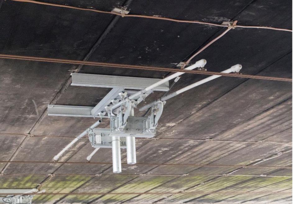
The reasons for these changes have been lost to time – but clearly the rule needed reassessment. If the value could be reduced then it could change some overbridges from needing intervention, to not needing it; or could significantly reduce the cost of an intervention (see figure 2).
Network Rail therefore asked us to review and revise that rule, using a combination of lineside measurement and statistical analysis. The techniques are covered in more detail in the January 2021 Journal, so I’ll concentrate on the outcome here.
Our analysis of over 850 train passages at speeds up to 125mph, and of almost 1300 pantograph passages (many trains having more than one pantograph) revealed that no uplift value was greater than 63.5mm, regardless of tension, speed or pan type. The mean + 3SD value of uplift was 54mm. However, one track at one site showed a clear anomaly compared to all the other data, probably indicating an OLE installation error. With this data removed the maximum value was only 46mm, and the mean + 3SD value 43mm. While this was not surprising given our empirical understanding of uplift, we were more surprised to see our expectations of seeing a clear relationship with tension, speed or pan type dashed. It is possible that this reveals the dominance of chaos in the behaviour of the system, with momentary reinforcement and destruction of the mechanical waves from each of the multiple pantographs being far more influential on the maximum uplift than the static
46
Figure 1: Typical bridge arm.
Figure 2: Build-up of clearances at an electrified overbridge.
characteristics of the system. It is also possible – though unproven – that pantograph set-up is variable between, and possibly even within, train fleets. As a result of this work, we recommended to Network Rail that the uplift rule be reduced from 70mm to 45mm. Our recommendation was accepted and is now included in NR’s new electrification policy1

EXAMPLE 2 - REMOVAL OF ICE LOADING
Another rule overdue for reassessment was that of ice loading. When the OLE catenary wire becomes coated in ice during extreme weather, it increases its weight, leading to higher values of sag at the contact wire that it supports, (see figure 3). Allowing for this additional sag increases the minimum overbridge soffit height, pushing more bridges into the intervention category.
On the Midland Mainline Electrification (MMLE) Bedford Kettering Corby electrification project, Atkins successfully argued that this allowance was not necessary. Network Rail then asked us to generalise the MML arguments to inform national policy. Our work showed that the conditions necessary for ice to form on wires in the UK almost never occur in combination with the conditions necessary for overvoltage events (such as lightning strikes) to occur. We also found that, prior to the year 2000, no allowance was made for sag due to ice, for the same reasons. This means that over 80% of UK overhead electrification has been built and operated without taking ice sag into account.
At some point it is possible that an engineer or project took the European Standard requirement to “consider the effects of ice load… on conductors”, and interpreted this as meaning ice loading had to be applied. This approach then propagated into other projects, before eventually appearing in Network Rail standards in 2018. This is a good example of the folly of implementing standards – or in this case an interpretation of a standard – without thinking deeply about its application to the specific railway.
There are countries in Europe when these conditions do occur in combination; but the UK is not one of them. Considering ice in this way and then using evidence to justify not making an allowance is perfectly compliant with the EN. We therefore recommended that ice sag allowance be removed from electrical clearance calculations at overbridges. This recommendation was also accepted and included in the new policy.
Figure 3: Icing occurs in the UK, but rarely at the same time as the conditions that lead to lightning overvoltages

These examples show how many of our current ways of designing OLE are based on decades-old rules and assumptions that may no longer be valid. We continue to work with Network Rail on other examples of this, and I hope to return to this theme in a future article.
CHALLENGES IN ADOPTING NEW RULES
As well as helping to set out the OLE design rules, we along with our colleagues across the supply chain are day-to-day users of these rules. We are currently involved with most of the active electrification projects in the UK, undertaking design on the next stages of MMLE, as well as the Haymarket to Dalmeny and Wigan to Bolton electrification schemes. For the last 18 months we have been tracking the development of Voltage Controlled Clearances (see the October 2021 journal) and other policy shifts within NR, and beginning to use some of the new approaches in our projects.
These policies are captured in two new documents; the aforementioned EPTAN 002 covers design through overbridges, while EPTAN 001 sets out a new process for risk assessing bridge parapets, and points the way to the removal of the current blanket requirement for 1.8m parapets on electrified lines, (see figure 4).
These EPTANs are underpinned by significant amounts of testing, simulation and research by Network Rail and its suppliers; but they also represent a very significant shift in electrification policy at overbridges, and because of this there is understandable nervousness from some parts of the industry towards their adoption.
The EPTANs are not aligned to current NR or Group Standards, and so project teams see risk to their projects, particularly regarding deviations to standards and gaining authorisation for the new approaches to enter service against fixed deadlines.
This raises a key question for the industry: how do we incentivise people to be more receptive to change and risk? We clearly need to do a better job at communicating and promoting the new approaches, and provide access to the evidence that underpins them – this article is part of that effort.
We also have to be more realistic and open about what is a fundamental change regarding what we are prepared to buy on new electrification projects. Many of you will by now be familiar with the term “Minimum Viable Product” (MVP), and electrification is certainly pursuing this approach but how do we define “viable”?
47
As we aggressively reduce Capex in pursuit of MVP, it is possible that we are increasing the Opex of some existing assets. This may mean that we are no longer always pursuing lowest whole life cost – a concept that has become almost sacred to the industry over the last twenty years. But when electrification is the only proven route to get UK rail to net zero, and government says costs are too high, we should not be afraid of challenging this idea.
British Rail were after all very good at making these trade-offs - they may not have always got it right, but to a large degree the electrified network we enjoy today is a result of that approach. In an era where cash is in short supply, the industry needs to relearn that art of balancing Capex and Opex, while being honest with our asset management colleagues and supporting them with the appropriate long-term resources to maintain the railway.
Project and asset teams will need to work together to find a new consensus; in many ways, the EPTANs are an acid test of the industry’s ability to change direction in the face of changing priorities.
THE DESIGNER’S ROLE
Atkins’ business is in electrification design, and with most OLE design in the UK being undertaken by the supply chain, we must also play our part in this shift. The design development phase is the most important in terms of cost reduction, at least in terms of deciding what gets built; by the time the first teams arrive on site, 80% of the Capex is locked in.
This is especially true of Engineering Stage 4 (or as it used to be called, GRIP4). So ES4 should not be done in a hurry – moving away from the old methods takes time. Staff must be retrained, new tools built or old ones adapted, and for each change in outcome the old consensus must be renewed between designer, project and asset manager. Innovating on multiple fronts in a hurry was tested to destruction on the electrification projects in CP5, and is a scenario that must be avoided in future.

But what else can you, as a designer, do to challenge costs? It can sometimes feel an impossible task, especially when you have a strong-willed client, a tight programme and a formidable set of standards to work to. But you could do a lot worse that start with the American Railway Engineer Arthur Mellen Wellington’s famous dictum - which being so often misquoted or Anglicised, I make no apology for reproducing here in full:
“It would be well if engineering were less generally thought of, and even defined, as the art of constructing. In a certain important sense it is rather the art of not constructing; or, to define it rudely but not inaptly, it is the art of doing that well with one dollar, which any bungler can do with two after a fashion.”
Arthur M Wellington, “The Economic Theory of the Location of Railways,” 1877
Here are a number of behaviours which I would argue any electrification engineer owes it to themselves, the industry and old Arthur himself to pursue.
Ask any OLE constructor what matters to them in terms of reducing transport time, storage costs and time on site, and they will tell you “standardise everything” – as with the production engineering approach so powerfully advocated for by Rob Sherrin in the April 2022 Journal.
So if you are a designer, push hard for a standardised, lean OLE configuration on your project. For instance on a two track open route railway, this should comprise more than 90% Single Track Cantilevers (STCs). (See figure 5). But this is not sufficient to deliver the standard railway. The “walkout” (or distance from track to structure in the horizontal plane) of every structure should be the same, small number – less than 3 metres is the goal. If there is an impermanent obstacle, get it moved – previous schemes have seen OLE structures built around scrap rail and redundant tracks; this and similar absurdities should not be tolerated.
Ancillary conductors – earth wires and auto transformer feeders –should be set at standard heights that should not be deviated from. Every effort should be taken to avoid the easy (but expensive) option of dropping a conductor to ground level; so as an industry we need to get comfortable with attaching these conductors – even bare live ones, suitably screened – to signal gantries as they pass through.

Taking Wellington at his word, we should also seek to remove equipment from the construction drawings altogether wherever possible. In recent years we have added facilities to deal with operational scenarios that may or may not occur – for instance bypass switches for neutral sections, only ever used in a very limited range of circumstances. We should now have sufficient operational experience of these to know if they are earning their keep – and if not, they should be deleted from future projects.
Another area that our Engineering ancestor would take a look at is number inflation. In recent years tolerances have tended to increase, and factors of safety multiplied. At some point we need to begin to challenge this and reverse the direction, lest we lose the business
Figure 4: EPTANs 001 and 002. 48
case altogether. So if the historical norm for vertical maintenance tolerance of track under a bridge is 25mm – which for the great majority of electrified bridges in the UK, it is then why are we using values four times higher, when those OLE systems still perform adequately?


It is no secret that our white collar staff costs on UK railway projects are much higher than elsewhere in the world; so another area that is ripe for challenge is process inflation. A cottage industry sprung up to deliver CP5 electrification projects probably necessarily, given that my generation of engineers had little experience of new electrification after a 20 year investment hiatus. But times have changed, the industry has matured and it is time to slim things down.
So – to take a single example which I have personal experience of –why is it necessary to have a workshop to determine which surfaces meet the definition of “standing” along a railway, and so need a safety clearance assessment to live parts? Such endeavours rarely attract less than half a dozen people, and can span multiple days. By this point in our journey it should be a one-person desktop task, following pre-agreed rules, (see figure 6).
Our colleagues in Scotland are leading the way in areas like these –for instance by challenging the need for expensive, time-consuming and pile-lengthening trial hole digging to find buried services. Instead they are trialing Ground Penetrating Radar (GPR), a quicker, non-destructive approach which is showing great promise. We hope to see trial holes eliminated by the end of CP6, or at least hugely reduced in number.
The white collar challenge doesn’t end there though; what about deliverables? When I spoke about this in Glasgow, I somewhat flippantly made the unevidenced claim that we produce more paperwork per Single Track Kilometre (STK) of electrification than any other country in the world. While this may raise eyebrows, I have yet to meet anyone who disagrees.
So designers and project teams should ask themselves, what is this deliverable for? Is it going to be used by teams on site, or is only going to be used by office staff?
If the answer is the latter, then its value should be questioned. It is evident over the last few years that a lot of the additional paperwork is used to build the safety case and evidence for compliance with the National Technical Specification Notices (NTSNs previously the TSIs); but there currently seems to be no upper limit on what can be asked for during this process. That too needs to change.
Yet another area to challenge is alignment of contracts and programmes. For instance, we have seen examples where the OLE design is at ES4 or even ES5, while the resignalling work needed to support electrification-readiness is only at ES3. This is not a sustainable scenario, and CP5 showed us that it drives abortive work and additional costs into electrification.
Figure 6: A standing surface, and some handrails (which are not a standing surfaces).
Figure 5: Standardised two track electric railway; UKMS100 equipment recently installed between Kettering and Corby.
49
Of course the timing of all of this challenge is key. As a programme of works gets closer to construction, the opportunities to save money reduce, and the potential for unintended consequences of disrupting the existing process increases. So all of the above challenges are ones that should be implemented aggressively during ES2 (feasibility) and ES3 (single option selection), and more carefully during ES4. If your project is at ES5, it is mostly too late. At this late stage, change should be resisted unless it is quick to implement and demonstrably has no unintended consequences.
THE CLIENT’S ROLE
I am also acutely aware that many designers are not used to pushing back in this way – it is a hard path compared to the easy one of delivering the same product as last time to the same standards. Pursuing these challenges involves taking some risk; and us designers are trained to worry about who will be liable if we get something wrong. Actual cases of design negligence in our industry are incredibly rare, but when that liability sits in your contract conditions, it changes behaviour. Network Rail ultimately owns these novel design risks, and so future design contracts could help with this issue by taking some of the liability off the table.
But designer challenge will not work as long as clients view the only role of the designer as that of producing drawings. This is obviously an important part of what we do, but designers have more insight than most as to where the inefficiencies in the OLE system and the design process lie. In my experience, designers actively dislike undertaking work that is wasteful or has no clear purpose, and they often have at least a half dozen good ideas that they’d like to implement given the chance. The industry would do well to listen to them more often.
CONCLUSION
We have seen in this article how UK electrification is at a crossroads; with the imperative to electrify most of the remaining non-electrified network in the face of an increasing climate emergency, colliding with a funding squeeze and mistrust from government on costs. RIA’s “Why Rail Electrification?” report made it abundantly clear that a continuous programme of electrification is the only plausible route to decarbonise Britain’s railways. The cost challenge will only be met by challenging the traditional rulesbased design process, and at Atkins we are playing our part, using simulation and measurement techniques combined with good oldfashioned engineering thought.

We’ve seen how emerging not-yet-standards poses a dilemma for all parts of the industry, and how designers, clients projects and asset managers all need to adapt at speed, getting out of their comfort zone to develop a new set of norms.
It is clear that this can only be achieved through a spirit of collaboration. Current procurement strategies often do not incentivise or reward the right behaviours, placing designers in a silo at arms length from either the installer and asset manager (hub and spoke) or from the client and asset manager (design and build). This often leads to a focus on cutting design phase costs and durations, rather than providing the time and focus to allow the designer to find ways to take cost out of the construction phase. The good news is that this means there are enormous opportunities available to us if we can find a way to collaborate as an industry, and productionise the construction process from the outset. Achieving this should be the main goal of electrification projects during Control Period 6 and beyond.
REFERENCES - 1. E&P Technical Advice Note (EPTAN) 12-21-002V1a “Electrical and mechanical clearances on overhead electrified railways”, para I1.5
OVERHEAD LINE ELECTRIFICATION FOR RAILWAYS
It gives me great pleasure to be announcing this new partnership with the PWI with regard to my electrification book, meaning that for the first time the hardback edition will be available for anyone to buy via the PWI website.
This marks the latest in a series of steps that the PWI has taken to expand its technical offer to the railway electrification community. Since joining the PWI three years ago I have been hugely impressed with how seriously the leadership team take their new mission to provide electrification engineers with a natural home – in the same way that they always have for the track engineering community. In recent years the PWI has run a series of electrification conferences, now includes at least one electrification article in every edition of the journal, and most recently has begun its annual electrification diploma course a UK first.
So I was very pleased to be approached by the PWI with the idea of them publishing my book. For those of you who aren’t aware, “Overhead Line Electrification for Railways”, now in its 6th edition, is an approachable and comprehensive study of OLE for beginners and trainees, or those in adjacent disciplines who want to gain an appreciation of the subject. Starting life as a free online download, it progressed to the point where there was sufficient interest in a hardback edition to justify a couple of print runs in 2019 and 2021. These were funded via kickstarter campaigns, which while a fun way to secure and fulfil orders, meant that anyone missing these narrow print run windows was not able to secure a copy.

Our new arrangement means that anyone wanting a physical copy can now buy one, without waiting for a kickstarter. I’m also very pleased to say that PWI recognises that the success of the hardback is in no small part due to the continued availability of the PDF version, and so that version will remain free to download.
Finally, the arrangement means that anyone taking the PWI Electrification Diploma will receive a copy of the book as part of the course.
Pre-order your copy from the PWI website; or to try before you buy, download the free version at www.ocs4rail.com
50
PWI ELECTRIFY
Over the next 30 years, as a global society, we must reduce carbon and other pollutants to net zero. The UK government has committed to reaching net zero by 2050, while in Scotland the national government is aiming to achieve the same target by 2045.
Consistent with these objectives, the only practical technology available to meet operational demand on most railways is Electrification.
#PWIElectrify
The #PWIElectrify campaign aims to highlight the vital role electrification engineers play in designing, maintaining, and managing railway infrastructure, the benefits of joining our Institution to electrification engineers, which include: significant discounts on tickets for the PWI’s technical seminars and PWI textbooks, access to our supportive community of likeminded rail infrastructure engineers, a range of continuing professional development opportunities, and support becoming professionally registered.
There are several ways the PWI can support electrification engineers.
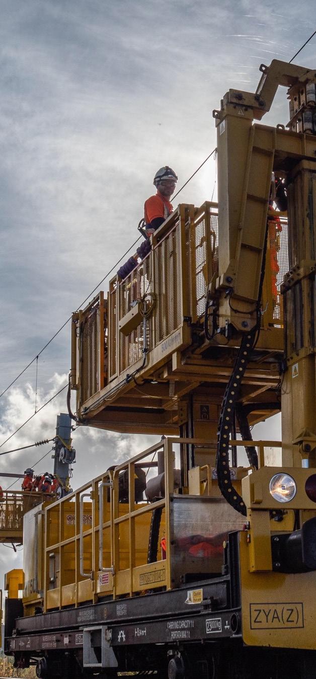
The PWI Journal and Knowledge Hub provides news about current rail projects and technical papers, giving you access to the latest technical thinking by industry experts.

At local Sections, you will meet colleagues from across the industry and hear presentations on a wide range of rail infrastructure engineering topics.
At every step of your career, the PWI can support you to achieve a professional title, such as EngTech, IEng, and CEng.
JOIN US BETWEEN
17 October & 30 November 2022 for the opportunity to win a signed copy of Garry Keenor’s book ‘Overhead Line Electrification for Railways’,
take advantage of discounted entry to our Electrification Seminar on 27 April 2023 in Sheffield.

WELCOME TO YOUR TRIBE
and
www.thepwi.org
51
PeterDearman
President president@thepwi.org
GPX is the UK’s largest supplier of specialist welding and grinding services.


Over GPX’s 19-year history of delivery to the rail sector, we have worked directly for Network Rail and Transport for London as well as for key contractors associated with major schemes to improve the UK’s rail infrastructure.
We strive to deliver the highest quality of service on every project that we undertake.
Our strength lies in our commitment to a well-trained, health and safety conscious workforce that are able to adapt to the changing needs of the rail industry.
We support the PWI in promoting safety on our railway infrastructure.

www.cleshar.co.uk 52


53
PROFESSIONAL REGISTRATION WITH
I made the decision this year to finally progress an application for Chartership. Having worked in the Permanent Way discipline for 20 years, and as a Civil Engineer for more than 27 years, experience was not a problem.

Rather it was about me feeling the need to demonstrate my competence via a formal process with external validation and verification. This external validation, and demonstration of continuing professional development and competence, are essential to be able to provide positive assurance of competence to funders and stakeholders in our safety critical industry.
The application process was detailed, yet straightforward, and all stages were clearly signposted. The right level of detail and support was always available, whether online or in person, to afford forward momentum within realistic timeframes.
Becoming a Chartered Engineer will assist my development, but it will also show within our team that our business supports the ongoing investment in their staff and promotes personal and professional growth within employment.
As a Network Rail employee early in my career, registering as EngTech with the PWI seemed a logical milestone. It signifies to others my investment and commitment within the world of railway engineering, and I’m sure it will help my applications for job roles stand out amongst my peers.
The process itself is professionally laid out and supported, with feedback given to help further best practice.

ALL PROFESSIONAL ENGINEERING INSTITUTIONS WORK TO THE SAME UNIVERSAL STANDARD AS LAID DOWN BY THE ENGINEERING COUNCIL...
& FERGUS TALK ABOUT
THE
WE JUST DO IT IN YOUR TECHNICAL DISCIPLINE & LANGUAGE. BECOME PROFESIONALLY REGISTERED WITH US THE PWI
MERVYN
PWI
Mervyn McCollam CEng FPWI
Head of Permanent Way - Infrastructure & Projects - Translink
Fergus Aspinall BEng EngTech MPWI GMICE
54
Graduate Civil Engineer Northwest & Central Route
PROFESSIONAL REGISTRATION
Professional Registration is an important step in pursuing a career in engineering and it lends itself to a ready-made career path, progressing through the grades as your experience broadens and deepens.
Putting those letters after your name (EngTech, IEng or CEng) instantly tells employers, clients and wider society that your competence and understanding of engineering principles has been independently assessed, that you have the knowledge, skills and professional attitude they value, and that you are committed to developing and enhancing your competence. It sets you apart from your non-registered colleagues.

The right professional registration title for you is based on your academic and professional competence: here’s a general guide…
We now have 300 of our members registered with the Engineering Council through us, at all titles: EngTech, IEng and CEng.
WILL YOU JOIN THEM?
We have now set our dates in 2023 for IEng and CEng Professional Review Interviews, and so the corresponding deadlines for submissions too.
Why not make a note of them in your diary now, so you can work backwards and set milestones to help you achieve your personal objective to achieve a professional qualification? It can be really useful to set a monthly reminder, so you can check in with your progress and set your next step.
Remember – interview dates and deadlines do not apply to EngTech applications. These are processed all year, as they are received – so do not delay!

Do get in touch with us if you have any queries or need any support.
We’d be delighted to hear from you.
Engineering Technicians apply proven techniques and procedures to the solution of practical engineering problems.
They hold Level 3 engineering/ technology qualifications and 2-3 years industry experience, OR 3-5 years industry experience.
Incorporated Engineers maintain and manage applications of current and developing technology, and may undertake engineering design, development, manufacture, construction and operation.
They hold Level 6 (Bachelors) engineering/ technology qualifications and 3-5 years industry experience, OR 5-10 years industry experience.
Chartered Engineers develop solutions to complex engineering problems using new or existing technologies, and through innovation, creativity and technical analysis.
They hold Level 7 (Masters) engineering/ technology qualifications and 3-6 years industry experience, OR 10-15 years industry experience.
The PWI is here for your journey and we would love to support you in your career aspirations.


Professional registration is open to any competent practising engineer or technician.
Different levels and pathways to registration are available, depending on your experience, training and qualifications.
FIND YOUR ROUTE TO REGISTRATION ON THE WEBSITE www.thepwi.org

Liz Turner REGISTRATION MANAGER Charlotte Boyce REGISTRATION EXECUTIVE +44 (0) 300 373 6000 (option
PROFESSIONAL REGISTRATION WITH THE PWI PROVIDES YOU WITH A GLOBAL BENCHMARK OF ENGINEERING EXCELLENCE, AND INDEPENDENTLY VALIDATES YOUR COMPETENCE AND COMMITMENT. WE ARE S UPPORTED BY NETWORK RAIL & TRANSPORT FOR LONDON
2) profeng@thepwi.org
Submission deadline (at least 6 wks prior) Interviews in w/c (to be held remotely) 31 October 2022 12 December 2022 6 February 2023 27 March 2023 2 May 2023 12 June 2023 31 July 2023 11 September 2023 30 October 2023 11 December 2023 55
Liz & Charlotte
over


d equipment specifically used for working on, or assisting in, the maintenance and r enewal of the railway infrastr uctur e in Gr eat Britain. It is a har dback, 360 page, full colour thr oughout, thr ead sewn publication with extensive colour illustrations. Included within it ar e compr ehensive details of:

s
r
■ On
■ Road/rail
■ Small
■ Owner
■ Manufacturer
On Track Plant 11th Edition can be obtained from Book Law Publications Copies cost £40.00 each - plus postage and packing. To obtain your copy, with secure online or dering, please visit: www.booklaw.co.uk Or ders can also be placed by telephone on: 0115 961 1066 Or by post from: Book Law Publications, 382 Carlton Hill, Carlton, Nottingham, NG4 1JA
of On- Track Pl ant - 11th Edition How to or der: 56
in the series of books first published
35 years ago. It is the definitive guide t o r a i l - m o u n t e d a n d
e l f - p
o p e l l e
track machines.
vehicles.
plant.
listings.
details.
Publishers


¬ quick and easy installation, even by hand > reduced costs ¬ simple and low-cost maintenance ¬ for di erent loads, climatic conditions and individual designs ¬ installed more than 80,000 times worldwide > decades of experience ensures technically mature systems the premium system for all level crossing systems. STRAIL (UK) Ltd. - Richard Whatley | Tannery Lane // Send / Woking // GU23 7EF // Great Britain Phone +44 (14 83) 22 20 90 // info@strail.com // www.strail.com THE PREMIUM SYSTEM. @strail_official @kraiburg strail simply reliable > typical STRAIL HELPFUL DOCUMENTS FOR MEMBERS Did you know that there’s documents for members on the PWI website? Here you’ll find branding support, Board meeting minutes, AGM papers, and more. Find this page here: www.thepwi.org/member-documents/ SITE VISIT TO THE K&ESR: PWI ASHFORD SECTION Read about this site visit in the NEWS pages. Find this page here: www.thepwi.org/news/ 57
The railway has a big role to play in helping tackle climate change through the sustainable service it provides to passengers and freight operators, thereby achieving its target of net zero carbon emissions by 2050 (2045 in Scotland). An industry approach is needed to address the complex environmental and financial issues at play. The industry will need to come together to deliver new infrastructure policies and standards which have sustainability at their heart. This will in turn drive innovation through new, improved ways of renewing and maintaining the permanent way, whilst maintaining an affordable lifecycle cost.


The seminar will tackle three railway industry themes critical to achieving a sustainable infrastructure; strategic thinking, infrastructure resilience, and designing for maintainability and sustainability. This comes at a time when the industry needs to challenge itself to collaborate, design, build, operate and maintain a safe and reliable railway infrastructure that delivers value for money for passengers and freight operators in a sustainable manner.

This event contributes to CPD.

SLIDING FRICTION BUFFER STOPS SKELTON Rawie Friction Buffer Stops provide protection for track ends worldwide. They can be designed to suit all types of rolling stock, accommodating varied train weights and speeds. Manufactured by A.RAWIE GmbH & Co. KG. Tel: 0049 541 91 2070 bufferstops@rawie.de www.rawie.de Supplied in UK & Eire by H.J. Skelton & Co. Ltd. Tel: 0044 1635 866877 sales@hjskelton.com www.hjskelton.co.uk PWI TECHNICAL SEMINAR SUSTAINABLE INFRASTRUCTURE design & maintenance BOOKING NOW OPEN: www.thepwi.org £85 MEMBER £150 NON-MEMBER £10 STUDENTS
LAST PLACES AVAILABLE! 10 NOVEMBER 2022 ST MICHAEL’S CENTRE, BRISTOL 58
Tighten
New
Switch tip alignment
Track Slewing

Switch Positioning Crossing Nose Alignment
Replacing Insulated Joint End Posts.
Adjusting gap on jointed track, Switches and Crossings and to correct for creep movement.

Replacing broken and worn fishplates using Master 35® Impact Wrench.

Adjusting breather switches utilising nearest fishplate joint.
Will remove the toughest of frozen/rusty Clips.
Use on outside track and inside the MMT in conjunction with Floating Trolley
Fastclip Remover
Will install and remove Clips quickly using our quick change Jaws

Rail Dip Measurement T R A C K M A I N T E N A N C E E Q U I P M E N T 59


40 Couper Street, Glasgow, G4 0DL T: 0141 552 5591 F: 0141 552 5064 E: enquiries@maximpower.co.uk W: www.maximpower.co.uk NEW Master 35® Impact Wrench & Tool Carrier NEW Lase Align Melvelle E Clip Remover Rail Gap Adjuster FItted with a more powerful LOW EMISSION EUR5 compliant engine. Faster, lighter weight and LOWER VIBRATION
EXPOSURE
and loosen all types of screwed fasteners and drill holes in Wooden Sleepers. Can be mounted onto existing and new Master Tool Carriers.
Battery, Diesel & Petrol Trackpack Improved version. Ideal for the following :
•
•
•
•


THE PWI LUNCH & LEARN PROGRAMME WELCOMES A SERIES OF PRESENTATIONS FROM INDUSTRY EXPERTS WHO WILL OFFER YOU A UNIQUE INSIGHT INTO DIFFERENT ASPECTS OF THE RAIL SECTOR FREE TO ATTEND, VISIT THEPWI.ORG
rail
traffic
rail.
RZ_SCHWEIZ 190x130 US.indd 1 22.09.2022 16:43:57 60
As a leading global supplier of
infrastructure, Vossloh is making a vital contribution to shaping tomorrow’s mobility. More than 130 years of experience combined with great innovative strength and a healthy dose of passion are helping to shift more
to
Smart Infrastructure. Sustainable Railways. vossloh.com
TECHNICAL BOARD


The Technical Board met on 19 July. The plan was to hold the Board in Huddersfield at the University rail research centre but due to a bizarre twist of fate involving the weather the meeting was held virtually. This day was predicted to be a day of extreme heat and people were warned not to travel due to potential delays and disruption, in itself a first for the UK.


The meeting started with a safety overview from Bill Cooke who has been a stalwart member of the Network Rail Safety Task Force team for over 2 years. He took us through the trials and tribulations of changing a culture from flag waving to protected track access. It was a focus on family and concentration issues that helped review the behaviour. The Board wished to note Bill’s great contribution to track safety.
Joan Heery updated us on the work of the Climate Change and Decarbonisation Committee and the plans for workshops in the autumn.

The October meeting will be in Huddersfield University, weather permitting and the first meeting of 2023 will be hosted by HS2 in Birmingham.


 Stephen Barber PWI CEO, updated the board on the business performance and strategic work of the PWI, and announced the dates of the next practical trackwork challenge to be held at the Kent and East Sussex railway from 1 - 4 November. I updated the board on training and registration with a new total of 300 registered PWI Engineers.
Gareth Evans, Professional Head of Track for Network Rail, talked about maintenance challenges particularly in the area of hot weather management and buckles which was very pertinent. He also mentioned adhesion issues and other derailment causes.
Stephen Barber PWI CEO, updated the board on the business performance and strategic work of the PWI, and announced the dates of the next practical trackwork challenge to be held at the Kent and East Sussex railway from 1 - 4 November. I updated the board on training and registration with a new total of 300 registered PWI Engineers.
Gareth Evans, Professional Head of Track for Network Rail, talked about maintenance challenges particularly in the area of hot weather management and buckles which was very pertinent. He also mentioned adhesion issues and other derailment causes.
For details of
please contact
(kate.hatwell@thepwi.org) 61
Corporate Members are fully involved in the development of the PWI, ensuring that our products and services meet the needs of the rail industry for technical expertise.
Corporate Membership
Kate Hatwell - PWI Operations Director
NEW MEMBERS
We’re honoured to have you on board and are thoroughly looking forward to working with you. Look out for our weekly email eBlasts and monthly email newsletters - we don’t want you to miss a thing! Remember to join our thriving social media network as we’d love to see you get involved! We’re here to help, so if you have any questions, then shout out!
Ashford: Shaun Hawkins, Bruce Waitson, Luke Hazlewood, Mark Line, Robert Coulson. Bengaluru: Satyam Sharma. Birmingham: Utsuk Shah, Benjamin Bicknell, Frederick Haddon, Richard Evans, Lwayo Banda, Michael England, Jason Fidoe, Mark Davis, Tom Bateman, Graham Smith, James Walker. Cheshire & North Wales: Sam Bonham, David Shipman, Peter McCracken, Toby White. Croydon & Brighton: Dr Alexandros Gavrilakis, Gyamfi Sarpong, Stephen Grogan. Edinburgh: Simon Mhoja, David Shirres, Stephen Greig. Exeter: Robert McClelland. Glasgow: Alasdair Brewster, Blair Grimley, Christopher Wright, David Somerville, David Maxwell, John Stark. International: Azlan Isa, Mohd Azuan Asri, Dr Chayut Ngamkhanong, Hudson Bouma, Eddie Mesina, Lyndsey Teng, Ubasen Uirab, Muhammed Shalapy, Bibhuti Bhusan Behera, Muhammad Usman Khan, Sanmit Kaimal. Irish: Aaron Brown. Lancaster, Barrow & Carlisle: Richard Mason, Neil Jones. London: Dr Sian Thomas, Luke Gray, Alex Irimia, Matthew Lock, Geoff Stickler, John Lloyd, Benjamin Cumming, John Wright, Ken Foster, Declan Lemon-Thomas, Babajide Jaiyeola, Janus Moorhouse, Jose Gomes, George Vodden, Conor Muller, Jordan Skey, Stefan Leuenberger, Ray Clarke, Alfie Fryett, Johnson Konan, Stephen Oluleye, Tomas Baar, Louis Barnett, Sam Pettit, Simon Staniforth, James Fuller, Christopher Clarke, Anna Saunders, Mohammed Ramzan Ali, James Bray. Manchester & Liverpool: Christopher Thompson, Christopher Pye, Phil Gerrard, Mark Dobson, Simon Bjork, William Lewis, Jamie Sherratt, Philip Armstrong, Tom Wilson, Thomas Neve, Roy Chapman, Martin O’Connor, Aleks Binder, Amelia Flood, Timothy Mulroy, Miguel Gillam, Alexander Briggs. Milton Keynes: John Hart, Mohammed Ghilani. North East: Christopher Wilson, Michael Dunderdale, Jack Devlin, Steven Shiel, Sara Mellor, John Lodge, Ganesh Kuttickattu Vijayakumar: Nottingham & Derby: Anne Watters, Allan Jones, Harry Kaur, Joanne Merritt, George Parker, Ashley Brown, Andrew Ryan, Rhys Hughes, Matthew Fallon, Maria Calero, Alexander Geary, Najee Rajapaksha Mudiyanselage, Chris Bridson, Nigel Turnbull. South & West Wales: Jason Paul Panes, Matthew Beer, Ian Brayley, Josh Ball-Hirst, Gareth Kinsey, Jaclyn O’Driscoll, Garret Doman-Cann, Robert Jones, Elliot Davies, Rachel Heath, Ceirion Hughes, Daniel Maggs. Thames Valley: Adam Quinn, Ross Cannon. Wessex: Marc Minikin, Matthew Beaumont, Christopher Oakley, Jay Warner, Aaron Scudder. West of England: Tim Harris, Dren Ahmeti, Ewan Dineen, Jay Carroll, Chris Fuoco. West Yorkshire: Gee Raw, Vania da Conceicao Goque, Ben Suitters, Harry Blanford, Alasdair Fleming, João Pombo. York: James Saunderson, Maximilian Ringrose, Christopher Ibbotson, Matt Handford, Jacob Whittle, Chris Dixon, Olivia Huntly, George Drum.
FELLOWSHIPS
Ashford: Robert Coulson. Birmingham: Tim Flower. Edinburgh: David Shirres. Glasgow: Keiren Sharkey. Irish: Kathy Kissane. London: Dr Sian Thomas, Chrisma Jain, Ray Clarke, David Smale. Manchester & Liverpool: Christopher Pye, Timothy Mulroy. North East: Steven Shiel. Nottingham & Derby: Allan Jones. South & West Wales: Ian Harris, Rachel Heath. Thames Valley: Jonathan Scott. Wessex: Aaron Scudder. West of England: Chris Fuoco, Rob Mashford. West Yorkshire, João Pombo. York: George Drum.
PROFESSIONAL TITLE
A huge well done to our members who have gained a professional title since the last Journal. This is an amazing achievement.
Engineering Technician: Ross Briddon, Liam Dance, Fergus Aspinall. Incorporated Engineer: Roger Wood.
Chartered Engineer: Peng Le, Sean Murray, Daniel Miles, Mervyn McCollam, Liam Allen.
PWI TRACK ENGINEERING DIPLOMA
Paula
Mateusz Krzemien, Alexandros Tsiachris, Karl Kiernan, Abdallah Ahmed, Abyed Chowdhury, Alawi Abdalla, Alex Trout, Arshya Jedari Salehpour, Ferdy Boswell, Fergus Aspinall, Hakam Al-Bustami, Kawsar Ahmed, Daniel Privett, Joseph Hurley, Khaled Ellithy, Madeleine Coyle, Connor MacFarlane, Abigail Theaker, Andrew Calvert, Damiano Acerbi, Jamie Sengun, Joshua Corney, Mohammed Usama, Muhammad Ahsan Faraz, Musa Khan, Paul Topping, Sajad Ali, Steven White, Lilian Ateng, Thomas Bishop, Charlotte Prommel, Fahad Munir, Prabhraj Singh Sandhu, Rupert Toppin, Tajwar Jasim, Umar Hussain, Michael Ainslie, Peter Davie, Sohaib Shahid, Andrew Simpson, Abdurrehman Desai, Ian Gregory, Ian Stanworth, Richard Heap, Suresh Palanisamy, Donal Buckley, Stephen Bullock, Nicholas Thorpe, Adam Collett, Peter Mitchell, Abdulaziz Alshaya, Ivan Dowman.
PWI S&C REFURBISHMENT
PWI ELECTRIFICATION ENGINEERING DIPLOMA
OBITUARIES
The full version of obituaries can be found on the PWI website.
Callejo Garvia,
Stephen Varley, Michael Clough, Lewis Blenkinsop, Daniel Wilders, Adam Broomhall, Thomas Jordan-Pearce, Lee Edwards, Joseph Thoburn, Harry Newgas, John Southgate, Michael Partner, Elliot Rose, Timothy Swarbrick, Darren Buttle.
Fraser Martin, Ibrahim Niamat, Vijay Kuldip, Joe Masters, Robert Clarkson, Shaun Hawkins, Mark McGuigan, Ruth Thomas, Paul Wills, George Hayllar, Lewis Bryant, Daniel Heath-Holmes, Phillip Terry, Jamie Davies, Michael Magbor
62
William Burns FPWI, Glasgow Section.
TECH TALK
Peter Dearman President president@thepwi.org
Steven Bell
Deputy President steven.bell2@babcockinternational.com
Chrisma Jain

Deputy President chrismajain@tfl.gov.uk
Nick Millington Past President nick.millington@networkrail.co.uk

Simon Blanchflower
Non-Executive Director simon.blanchflower@eastwestrail.co.uk


Prof. William Powrie
Non-Executive Director w.powrie@soton.ac.uk
Michelle Nolan-McSweeney
Non-Executive Director michelleusrm@aol.com
Andy Tappern
Non-Executive Director andy.tappern@networkrail.co.uk


Brian Counter
Technical Director technicaldirector@thepwi.org
Andy Steele
Technical Manager andy.steele@thepwi.org

Mike Barlow
Technical Manager mike.barlow@thepwi.org


Liz Turner

Registration Manager liz.turner@thepwi.org
Registration Executive profeng@thepwi.org
Paul Ebbutt
Professional Registration Development Officer (South) 07887 628298 developmentofficersouth@thepwi.org
Brian Parkinson
Professional Registration Development Officer (North) 07876 578905 developmentofficernorth@thepwi.org
Chief Executive Officer stephen.barber@thepwi.org
Kate Hatwell Operations Director kate.hatwell@thepwi.org

Joan Heery

Membership Director joan.heery@thepwi.org
Sara Green
Membership Secretary secretary@thepwi.org
Michelle Lumiére
Head of Marketing michelle.lumiere@thepwi.org

Kerrie Illsley
Creative Manager kerrie.illsley@thepwi.org journaleditor@thepwi.org

Luke Goude
Marketing Executive marketing@thepwi.org
Tech Talk is a private forum where members can discuss, debate and share views on all things related to rail technology. Members can ask questions and make comments about the technical articles that are published in the PWI Journal, as well as react to our technical seminars, Boards and relevant news.
We encourage healthy debate and differences of opinion, but ask that contributions remain friendly and respectful at all times. Simply request to join!
www.linkedin.com/groups/8862498/

YOUNG ENGINEERS SECTION

AMBASSADORS
PROFESSIONAL REGISTRATION
This virtual Section has been formed on LinkedIn and provides a central location for all the younger members of the rail community to engage whilst remaining a member of your regional home Section.

The Young Engineers Section is a place to exchange thoughts, ideas, views and challenges you may be experiencing in your role as a young person working in the rail industry. It’s a place to gain and offer support, to meet likeminded individuals, and to participate in social activities as the group becomes more defined. Simply request to join!
www.linkedin.com/groups/8865220/
This forum connects PWI Ambassadors to discuss ideas, suggest collaborations and to receive updates and announcements from the central team.
PWI Ambassadors are free to post comments, ideas and suggestions to fellow Ambassadors or for the attention of the PWI central team. We continue to seek new Ambassadors and Young Ambassadors, and aim to appoint at least one Ambassador for every Corporate Member. If you wish to volunteer or nominate a colleague, please contact: marketing@thepwi.org
www.linkedin.com/groups/8913254/
This group is for all those embarking on their Professional Registration journey, as well as those who have already completed the process. Connect with each other, raise questions, discuss challenges and gain support from your peers.

We encourage members to treat this as an alumni network for PWI Professional Registration, allowing you to make friends and stay engaged with others who have undertaken the same journey, and to offer your experiences and mentorship to others when possible. Simply request to join!
www.linkedin.com/groups/8976547/
Stephen Barber
Charlotte Boyce
63
CENTRAL
ENGLAND VICE PRESIDENT Mark Downes vpcentral@thepwi.org
BIRMINGHAM Secretary: Tony Morgani birmingham@thepwi.org Venue: 2nd Floor, Network Rail, Baskerville House, B1 2ND / WSP Offices, 100 The Mailbox, B1 1RT
MILTON KEYNES Secretary: Kevin Thurlow 07802 890299 miltonkeynes@thepwi.org Venue: Auditorium, The Quadrant, MK9 1EN
NOTTINGHAM & DERBY Secretary: John Garlick 07532 071727 nottingham-derby@thepwi.org Venue: Aston Court Hotel, DE1 2SL / Jury’s Inn Hotel, NG2 3BJ
IRELAND
VICE PRESIDENT Cathal Mangan cathal.mangan@irishrail.ie
IRELAND Secretary: Joe Walsh 00 353 872075688 pwiirishsection@gmail.com
NORTH EAST ENGLAND VICE PRESIDENT Phil Kirkland vpnortheast@thepwi.org
NORTH EAST Secretary: Phil Kirkland 07899 733276 northeast@thepwi.org Venue: Newcastle College Rail Academy, NE10 0JP
WEST YORKSHIRE Secretary: Martin Wooff 07487 652622 westyorkshire@thepwi.org
YORK Secretary: Louise Walley york@thepwi.org Venue: Network Rail Meeting Rooms 0.1, George Stephenson House, YO1 6JT
NORTH WEST ENGLAND & NORTH WALES VICE
PRESIDENT Lynne Garner vpnorthwest@thepwi.org
CHESHIRE & NORTH WALES Secretary: Peter Veryard cheshire@thepwi.org Venue: YMCA, 189 Gresty Road, Crewe, CW2 6EL
LANCASTER, BARROW & CARLISLE Secretary: Philip Benzie lbc@thepwi.org 01704 896924 Venue: Station Hotel, PR1 8BN / Network Rail, CA28 6AX / Network Rail, CA1 2NP / Network Rail, Warton Road, Carnforth LA5 9ET
MANCHESTER & LIVERPOOL Secretary: Richard Wells manchester-liverpool@thepwi.org 07817 302652 Venue: Online until further notice
SCOTLAND
VICE PRESIDENT Hannah Persson vpscotland@thepwi.org
EDINBURGH Secretary: Mark Taylor edinburgh@thepwi.org 07710 959630 Venue: The Scots Guards Club, EH12 5DR
GLASGOW Secretary: Angus MacGregor glasgow@thepwi.org 07775 544509 Venue: WSP Offices, 7th Floor, G1 3BX
SOUTH CENTRAL ENGLAND
VICE PRESIDENTS Anup Chalisey & Darren Sharp vpsouthcentral@thepwi.org
LONDON Secretary: Sean Tarrant london@thepwi.org 07764429211 Venue: RSSB, 1 South Place, London, EC2M 2RB
THAMES VALLEY Secretary: Richard Antliff thamesvalley@thepwi.org 07804 329497 Venue: Network Rail Offices, Hawker House, 5-6 Napier Court, Napier Road, Reading, RG1 8BW / Reading Railway Club (GWRSA), 6a Station Approach, Reading, RG1 1NB
WESSEX Secretary: Paul Meads wessex@thepwi.org 07771 668044 Venue: The Eastleigh Railway Institute, SO50 9FE / Network Rail Offices, Waterloo Station, SE1 8SW
SOUTH EAST ENGLAND
VICE PRESIDENT Jonathan Bray vpsoutheast@thepwi.org 07976 199011
ASHFORD Secretary: Colin Burnikell ashford@thepwi.org 07801 913562 Venue: Online until further notice
CROYDON & BRIGHTON Secretary: Colin White croydon-brighton@thepwi.org 07845 316042 Venue: Mott MacDonald House, CR0 2EE
LONDON Secretary: Sean Tarrant london@thepwi.org 07764429211 Venue: RSSB, 1 South Place, London EC2M 2RB
SOUTH WEST ENGLAND & SOUTH WALES
VICE PRESIDENT Andy Franklin vpsouthwest@thepwi.org 07901512293
WEST OF ENGLAND Secretary: Simon Warren western@thepwi.org Venue: Engine Room, Atkins, SN1 1DW

EXETER Secretary: James Grant exeter@thepwi.org Venue: Mercure Exeter Rougemont Hotel, Queen Street, EX4 3SP
SOUTH & WEST WALES Secretary: Andrew Wilson southandwestwales@thepwi.org 07974 809639 Venue: Network Rail Offices, CF10 5ZA / Clayton Hotel Cardiff, St Mary Street, Cardiff, CF10 1GD
INDIA
BENGALURU Secretary: Srinagesh Rao bengaluru@thepwi.org Venue: Arcadis Sez Office, Bengaluru, Karnataka 560045, India
INTERNATIONAL CONTACTS
MALAYSIA pwimalaysia@gmail.com
NEW SOUTH WALES info@pwinsw.org.au
QUEENSLAND Robin Stevens robin.stevens@qr.com.au
Section
great places to learn about rail projects and new technical developments, and
rail professionals. 200+ SECTION MEETINGS A YEAR! 64
PWI
meetings are
network with other


PERMANENT WAY INSTITUTION MEMBERS SAVE £5 SPECIAL SUBSCRIPTION OFFER - SPECIAL SUBSCRIPTION OFFER Established for 50 years, Modern Railways has earned its reputation in the industry as a highly respected monthly railway journal. Providing in-depth coverage of all aspects of the industry, from traction and rolling stock to signalling and infrastructure management, Modern Railways carries the latest news alongside detailed analysis, making it essential reading for industry professionals and railway enthusiasts alike. TO CLAIM YOUR DISCOUNTED SUBSCRIPTION Simply enter code PWIMR in the coupon code box at the checkout page when ordering online at: shop.keypublishing.com/mrsubs Alternatively, call: 01780 480404 quoting code PWIMR to the operator Lines open 9.00-5.30pm Monday-Friday. All details correct at time of going to press. Offer ends 31 December 2022 *Offer not valid on Direct Debit subscriptions. JANUARY 2022 £5.49 modernrailways.com NEWS, VIEWS & ANALYSIS ON TODAY'S RAILWAY NEW TRAINS FOR WALES TfW unveils Stadler ‘231’ HS2 TRAINS HITACHI/ALSTOM JV WINS £2bn DEAL UNITED IN ANGER North and South feel the pinch TRANSPENNINE PROMISES BROKEN Integrated Rail Plan disappoints Mayor and Government at loggerheads NOVA 3s TO CLEETHORPES | CROSSRAIL TRIAL OPERATIONS | FLEET RELIABILITY REPORT ‘MANAGED DECLINE’ AT TfL? IN-DEPTH ANALYSIS OKEHAMPTON REGAINS REGULAR SERVICES GBR LEGISLATION DELAYED SALISBURY COLLISION RAIB highlights wheel slide issues Time to act on rail adhesion RAIL PLAYS ITS PART AT COP26 Climate Train transports delegates Hydrogen and battery train demos CAPITAL GAINS Overground to Barking Riverside Elizabeth Line opening nears New Piccadilly Line trains www.modernrailways.com NEWS, VIEWS & ANALYSIS ON TODAY'S RAILWAY HS2 ROLLING STOCK BATTLE Siemens contests contract award RAIL INNOVATION FREE RAIL INNOVATION SUPPLEMENT COMPULSORY RESERVATIONS A good thing for inter-city travel? FREE SUPPLEMENT! HS2 REPORT - ISSUE 2 INDUSTRY URGED TO ACT ON CARRIAGE NO2 LEVELS D TRAIN IN AMERICA MISSING MILLIONS State control again after undeclared £25m DfT probe overshadows City Beam ‘707’ launch SOUTHEASTERN’S Rolling programmeelectrification Hydrogen in the Highlands Preparing for COP26 Glasgow Subway at 125 Queen Street transformed Edinburgh Trams to Newhaven SCOTLAND SUSTAINABILITYTARGETS SPECIAL REPORT www.keymodernrailways.com NEWS, VIEWS & ANALYSIS ON TODAY'S RAILWAY 011/22 ON A SUBSCRIPTION TO 65
LEARN WITH US


TRAINING DELIVERED BY INDUSTRY EXPERTS
THE PWI IS HERE FOR YOUR ENTIRE CAREER JOURNEY
PWI training started over 100 years ago and has been providing high level technical training for
since. Our courses are designed to develop skills and knowledge in all aspects of rail infrastructure
your journey to professional
EARTHWORKS, DRAINAGE & OFF-TRACK ENGINEERING COURSE
One course, one week.
This course provides delegates with the knowledge, understanding, and insights necessary to manage the risks presented by earthworks, drainage and associated Off-Track railway infrastructure assets.

PROGRAMME AIM
Delegates will learn about track formation, earthworks, drainage and water management, vegetation, level crossings, line-side security, and their relationships with interfacing engineered systems such as track. Weather related effects will be examined and the potential longer term impact of climate change explored.
Through theory, worked examples, case studies, and exercises, attendees will gain an appreciation of good practice in the design, installation, and ongoing safe management of critical Off-Track assets.
Not only will you
an
ADVANCED TRACK TECHNICIAN COURSE
One course, three weeks.
The aim of this course is to give delegates advanced technical knowledge and understanding of track systems, and their associated methodologies and plant. It is comprised of three consecutive modules and involves 120 hours of taught study all mapped to HE Level 4.
PROGRAMME AIM
Delegates will learn how innovations in survey, design, maintenance, renewal, and project work can be harnessed to help make safe and efficient plans. Diversity and sustainability issues will be explored, as will the interdependencies between the various engineering functions and train operations, so that key management skills including decision making, prioritisation, record keeping, data analysis, and report writing are developed. Practical skills will be developed in plain line and S&C surveying and inspection, rail and rail defect management, mechanised alignment maintenance, and rail stressing.
ROUTE TO ENGTECH
There will be additional support throughout the course for those wishing to achieve EngTech registration. Subject to a satisfactory application and review, delegates will be awarded the EngTech title upon completion of the course.
S&C REFURBISHMENT TRAINING COURSE
One course, one week.
This course provides the knowledge and skills needed to plan and deliver safe and effective S&C refurbishment. The PWI has harnessed the joint experience of expert trainers to create a course that equips track engineers and managers to specify, design, and implement effective refurbishment of S&C.
The processes for scoping, specification and quality assurance have been produced in conjunction with Network Rail and identify best-practice. The course is mapped to level 5 (HND) and can become a partial step towards IEng professional registration.
PROGRAMME AIM
Delegates on this course will gain a comprehensive detailed knowledge of switches and crossings and how to undertake refurbishment safely, efficiently and to the required engineering quality. The course will cover both the track assemblies and the trackbed under switches and crossings. Participants will undertake detailed analysis and inspection of layouts so that they can scope and specify work correctly to provide the necessary life extension of the layout.
The course will then ensure that delegates understand the various maintenance interventions suitable for switches and crossings and its components and can plan those required in the correct sequence.
engineers and professionals operating at all levels ever
repairs, renewals and projects – and can help you on
registration.
gain
understanding of the underlying theory, you will develop an appreciation of the real-life challenges facing engineers from our team of experienced rail infrastructure lecturers.
See page 25 for full details. See page 29 for full details. 66
CAREER TRAINING UPDATE
BESPOKE TRAINING
Customer designed, global delivery.
The PWI offer bespoke or customer designed training that can be delivered anywhere in the UK or beyond.
We provide face to face delivery in classrooms, hotels or on-site, as well as virtual live classes for up to 24 delegates. This includes individual and group work during, between or after sessions.
Geared toward basic introductory rail infrastructure for non-engineers such as project managers and operators, we recommend a designed formal assessment process facilitated by our skilled and experienced trainers.

Delegates benefit from a friendly, supportive environment with experts who take a human approach to providing a fulfilling and enjoyable experience. Social interaction and networking sessions are also encouraged.
Visit the website to read more about our accreditation and resources including specialist training towards Engineering Council professional registration and provisions of specialists in any rail area.
TRACK ENGINEERING DIPLOMA
One Diploma, three modules.
Delegates will be taught by experienced rail infrastructure engineers who will share their wealth of experience. Attendees will receive three technical textbooks, comprehensive course materials and coursebooks with worked examples to support their learning.
PROGRAMME AIM
Delegates gain an understanding of the principles of the theory and practice of track engineering in the UK. It is comprised of three consecutive modules and involves 100 hours of taught study all mapped to HE Level 6.
Upon successful completion of all three modular assessments, candidates will be awarded the PWI Diploma in Track Engineering. These courses are aimed at newly qualified and experienced engineers and will give delegates the knowledge and skills needed for professionals in track engineering.
TOP-UP QUALIFICATION TO IENG


The PWI Track Engineering Diploma is a form of further learning and, together with a short Supplementary Report, fills the academic gap to IEng for those with relevant HND or Foundation degree qualifications.
ELECTR IFICATION ENGINEERING
DIPLOMA
One Diploma, three modules.
The Diploma is comprised of three consecutive modules involving 100 hours of taught study all mapped to HE Level 6. Delegates will receive a technical textbook and comprehensive course materials with worked examples to support their learning.
These courses are aimed at newly qualified and experienced engineers and will give delegates the knowledge and skills needed for professionals in electrification engineering.
PROGRAMME AIM
Delegates gain an understanding of the principles of the theory and practice of Overhead Line Electrification engineering in the UK. The trainers are all very experienced electrification engineers who have spent their careers designing, constructing, operating and maintaining systems in the UK and abroad.
Upon successful completion of all three modular assessments, candidates will be awarded the PWI Diploma in Electrification Engineering. Further development of supplementary modules will take place late next year to include 3rd/4th rail and side contact systems alongside power and distribution.
The PWI training team have delivered 20 courses in 2022 and I am convinced that we have made significant differences to the knowledge and understanding of rail infrastructure. We have encouraged many delegates to join the PWI and continue on their journey towards professional registration. I have had some great feedback from successful participants who have achieved far greater than they expected by blending their valued experience with new skills and knowledge. This includes many who for whatever reason did not fully pursue further education and went straight onto the coalface! The excellent teaching is a credit to our specialist and “long in the tooth” (their words) experienced trainers. The best comments include their appreciation of stories of what we did in the past and how we overcame technical and operational challenges. There are many hundreds of PWI certificated engineers and technicians out there so why not book yourselves in and join our “tribe”.
BRIAN COUNTER - TECHNICAL DIRECTOR PWI - technicaldirector@thepwi.org
I encourage people to do training to gain confidence to tackle new areas and prepare for professional status.
67
Almost everyone who attends PWI courses could easily be EngTech MPWI.
The concept of digital delivery has been around since the late 1990s, underpinning the integration of planning, design, construction, and operation, and system integration across engineering disciplines.


Safe and effective railway infrastructure relies on such integration and is a natural home for the digital techniques which enable it. But how far has our industry actually progressed in using data to make better and faster decisions?


The 2023 PWI North West Technical Seminar will explore, through recent case studies, how our industry is using digital delivery to innovate in engineering, construction, maintenance, and safety.


Delegates will see how digital techniques - including BIM, advanced surveying, asset tagging, and digital twins - deliver efficiencies in survey, design, and asset management, and will hear from suppliers who make the application of digital technology straightforward and practical.


This event contributes to CPD.


BOOKING NOW OPEN: www.thepwi.org £85 MEMBER £150 NON-MEMBER £10 STUDENTS SPONSORSHIP AND EXHIBITOR SPACE AVAILABLE. Contact +44 (0) 300 373 6000 / secretary@thepwi.org
2 MARCH 2023 MANCHESTER CONFERENCE CENTRE
TECHNICAL SEMINAR RAILWAY INFRASTRUCTURE DELIVERING DIGITALLY 68
PWI
