9 minute read
Improving track worker safety with geo-fencing

by The PWI

AUTHOR: Jay Moorhouse CEng FICE FCIHT FCMI
Jay is the Chief Operating Officer of Onwave, Jay spent over 20 years as a Civil Engineering Contractor delivering major projects across the UK in a variety of sectors, and became responsible for infrastructure projects in the Southeast of England for BAM. Jay is a Fellow of the Institution of Civil Engineers, the Chartered Institution of Highways and Transportation and the Chartered Management Institute and a Member of The PWI. Jay has been leading Onwave in supporting the Network Rail Safety Task Force team in looking at how geofencing technology can deliver Track Worker Safety improvements.
Advertisement
AUTHOR: Ken Lambert FPWI
Ken is one of the senior leaders within the Safety Task Force and led improvements to maintenance Planning and the introduction of new safety technology. Ken has been in rail for 35 years and has made many changes and improvements to modernise the ways front-line staff work. Ken is a Fellow of The PWI, and in the last three years, Ken has been working with the routes and their teams by completely changing the way they work on and near the line with plans to further reduce the remaining 1% of open line working.
There is a relentless drive across the Rail sector to improve safety for all track workers, a drive that is passionately led by the Network Rail Safety Task Force team who are helping to pioneer new ways of working including the implementation of new technologies on the railway.
A key factor in many incidents relating to track worker safety is a loss of situational awareness, where people lose context of their location, become distracted or disoriented and can inadvertently step into harm’s way.
An emerging technology that prevents this loss of situational awareness is geo-fencing, and the OWL technology developed by Onwave UK is at the forefront of this new technology.
Geo-fencing technology was originally invented in the 1990s, being patented in 1995 by an American inventor, Michael Dimino, with many of its early uses related to vehicle tracking, military, or security use cases. Onwave has been delivering geo-fencing technology since 2017, originally to highways maintenance teams to prevent accidental environmental damage to protected habitats or inadvertent spread of invasive species.
The Onwave management team have a rail background and so the natural thought process following this initial highways use case was how could this technology be applied to keep people safe on the railway?
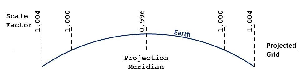
The basic premise of geo-fencing technology is that people, vehicles, or items of equipment have their location monitored by GNSS (Global Navigation Satellite System) technology, the most common form of which is GPS, which is generally referred to. GNSS solutions use a variety of satellite constellations for positioning, including GPS, GLONASS, Beidou and Galileo.
This helps to provide enhanced accuracy by not relying on a single satellite constellation. The signal takes some time, (milliseconds), to be transmitted from the satellite to a device. Using GNSS, three Figure 1: RTK diagram.
or more satellites from different constellations can be used to triangulate the position of the receiver. Although a good and simple technique, GNSS technology is not 100% accurate as atmospheric conditions can and do affect accuracy.
A core challenge in taking this technology onto the railway was this level of accuracy; for many use cases standard GNSS accuracy of 1 to 3m is acceptable, but when working on rail infrastructure, potentially with adjacent open lines then a much higher degree of accuracy is required. As such, Network Rail has a requirement of repeatable accuracy of better than 0.5m. Traditional GNSS technology, (such as smartphones), receive signals directly from a satellite and estimate location using the differential in times transmitted from multiple satellites. These signals can be impacted by environmental factors which reduce the overall accuracy of GNSS technology.
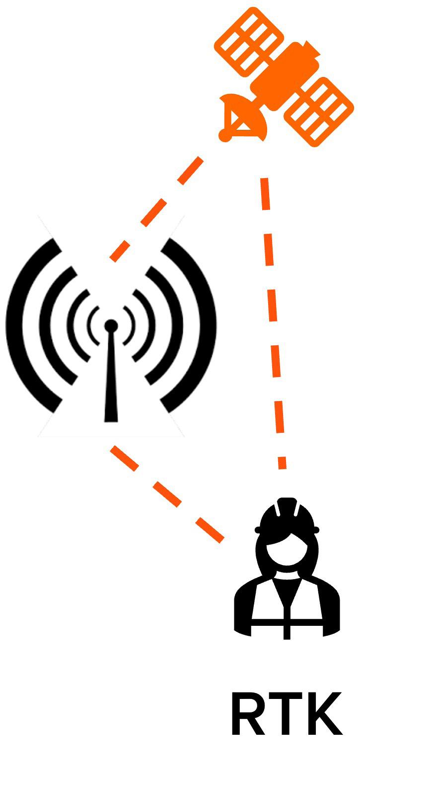
OWL uses a number of location positioning technologies, however, a key method in achieving the 0.5m accuracy for Network Rail is the use of Real-time Kinematic (RTK) technology. RTK is commonly used in surveying, and it increases the accuracy of a GNSS position using base-stations that send out correctional data to a moving receiver.
RTK uses a carrier phase measurement technique to better determine the location of the receiver. The base-station verifies the location data received in this form against its known fixed location and then generates a correction signal, which is transmitted in realtime to a receiver, in this instance a wearable device. For example, the base station knows it should receive a signal in 73 milliseconds, but if it is taking 84 milliseconds there is an 11-millisecond correction required.
The RTK will calculate the 11-millisecond correction which is then fed back to all devices within the necessary area. Each piece of correction data has a range where it is useful and then the servers choose the best and closest correction data and send the data to the wearable devices to correct themselves to less than 30-to-40 millimetre accuracy (see figure 1). A single base-station can send correction signals to thousands of devices and so large-scale operations can be covered with no loss of service or accuracy.
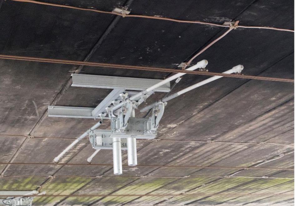
The reporting frequency for devices is configurable and for a safety use case such as this, the interval is set at less than a second so that alerts are triggered as soon as a geo-fence, (a ‘virtual’ fence), is crossed. Figure 2: Installed base-stations.
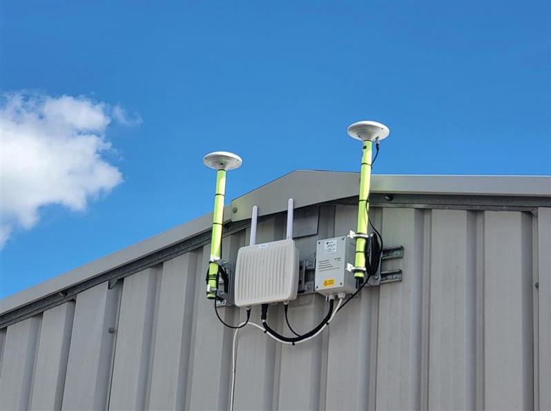
Base-stations typically have a fixed location, providing coverage for a distance of up to a 20km radius and so can deliver RTK accuracy across a wide area and can be leveraged for a variety of use cases outside of the main geo-fencing focus (see figure 2). As an example, another emergent use of RTK is for the operation of drones and ensuring they are accurately positioned, which is another example of how RTK use is becoming more prevalent across technologies where location accuracy is an important factor.
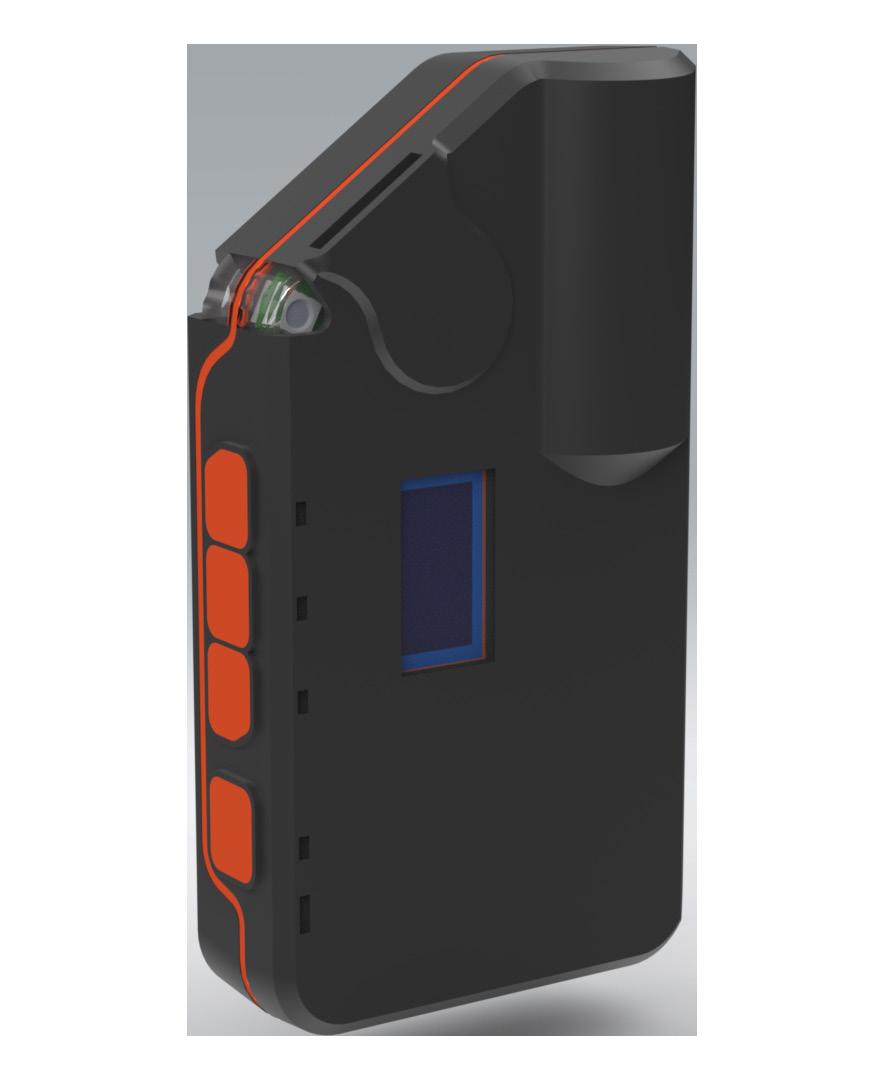
The geo-fences themselves are created on a digital map interface and alerts are triggered should a person or vehicle cross one of these geo-fences. The location of people and plant is monitored using a small wearable device that acts as a GNSS receiver, though with the added ability to alert the wearer using a combination of audible, haptic, and visual alarms appropriate for use in the rail environment. These alarms can be configured based on the specific alert required.
A key consideration for the use of geo-fencing has been the need for user privacy to be maintained at all times. To ensure this is the case, all users on the system are anonymised and OWL also has the functionality to stop monitoring at a pre-defined boundary, in this case the Network Rail boundary fence line. As such, no personal
data is collected and there is demonstrable privacy protection for the end user. Whilst no personal data is collected, the system will be able to highlight locations on the railway where alerts are being triggered providing insight into areas where possessions may perhaps be planned differently to reduce future risk.
This reporting frequency directly affects the battery life of the wearable devices, however at the maximum, (sub-second), reporting rate, the wearable devices have a battery life of greater than 12 hours and so will safely cover the longest allowable work shift.
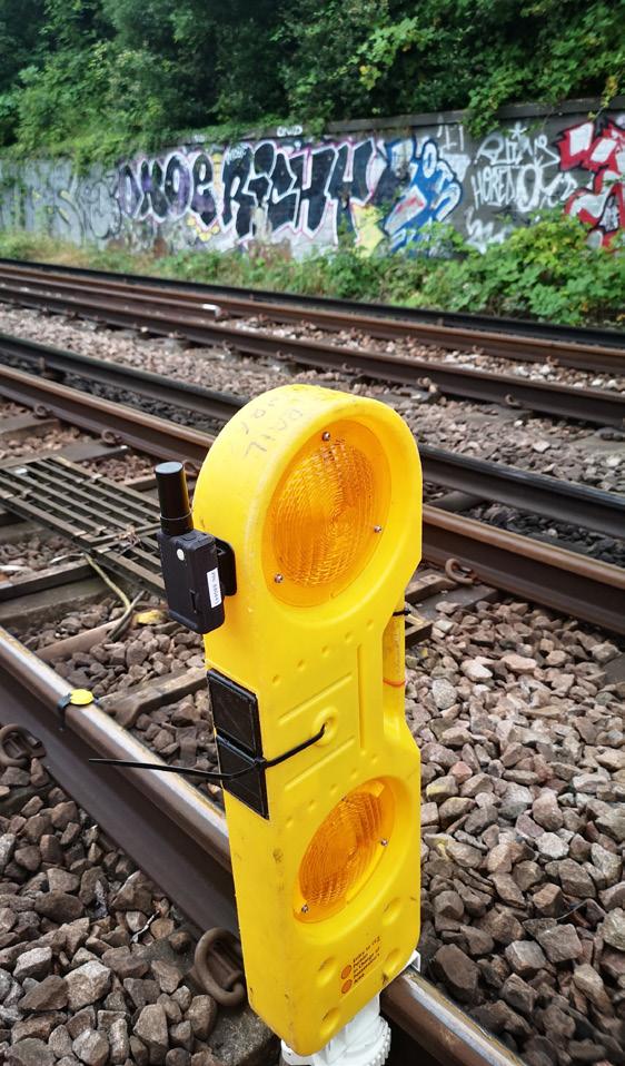
To date, the main focus has been on ensuring the situational awareness of track workers, however, there are many other possible use cases for geo-fencing technology on the railway. For example, devices can be attached to marker boards or isolation straps and geo-fences created to show the locations that these are to be deployed ensuring they are installed at the correct location.
It is also possible to create dynamic geo-fences around items of plant and equipment. The benefit of this is two-fold in that it creates exclusion zones to reduce people/plant interface risk, whilst also making it simple to verify that plant and equipment have been removed from track prior to removal of a possession or isolation.
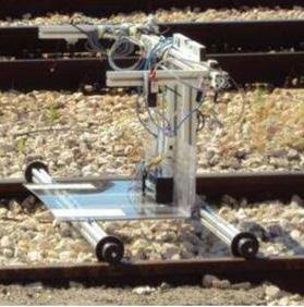
A further use case is in that of ‘runaway’ alerting. The risk of runaway plant such as track trolleys, although much reduced, still remains a risk for track workers. Using geo-fencing, alerts can be triggered should a track trolley move without its operator present, with these alerts triggered to all people in the vicinity making them aware that a hazardous situation may have arisen and again to raise their situational awareness.
The wearable devices themselves are intelligent and have a number of secondary safety features such as the ability to detect lack of movement in an individual as an indicator of a potential injury and can also detect falls, in both cases having the ability to trigger an alert to a supervisor should either of these events occur.
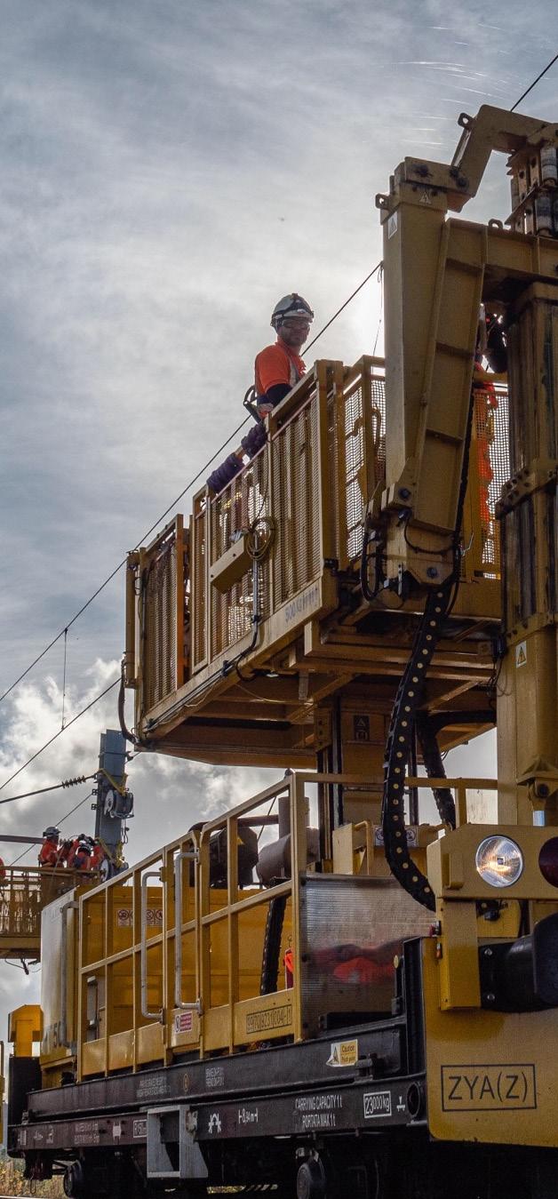
A period of intensive trials was conducted in the Summer of 2021, with maintenance teams from Network Rail carrying out various tasks including patrolling, permanent way and overhead line work in a variety of locations including cuttings and embankments to test geo-fencing in various scenarios. The safety benefits were readily apparent to the end users and the technology evidenced repeatable high levels of accuracy across different use cases and in locations where connectivity would typically be perceived to be a challenge.
RTK technology has few limitations, however, it does require a clear view of the sky to be able to reliably communicate and so providing the accuracy levels required in areas such as tunnels and stations is not currently supported. Solutions for such use cases are available leveraging the current OWL hardware, however these will require live testing similar to that undertaken for the other use cases prior to active use in a rail environment. This is likely to be a focus area in 2023.
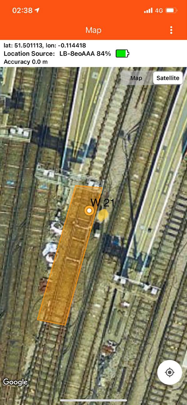
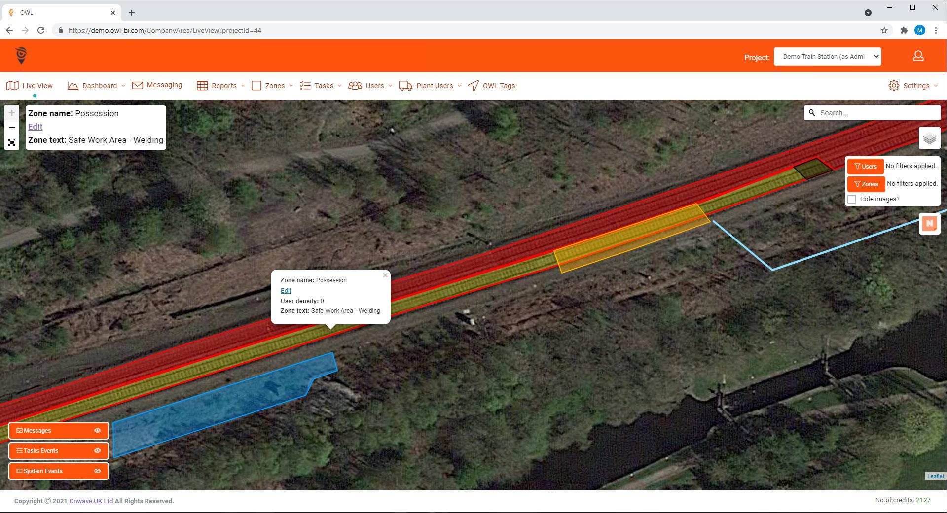
In terms of creating accurate geo-fences, track information was provided by the Network Rail Geo-spatial team and simply uploaded to the portal to create the geo-fences. This is typically completed using .kml or .kmz files which are commonly used geo-spatial file conventions. Once each geo-fence is created then the alerts are configured depending on the nature of the zone and whether the user is entering, leaving or if the zone is approaching its expiry time. Geo-fenced zones can be colour coded and labelled and may also have documents attached, for example, asset information (see figure 3).
As well as the wearable device, a mobile application is available for Supervisors allowing them to view geo-fences and select and retrieve information attached to a geo-fenced Zone. This provides a Supervisor with an enhanced context of their location, especially if working at a new site that is unfamiliar to them. Geo-fences once created can be activated and de-activated, making them simple to deploy for regular periodic operations without the need to create the geo-fence environment again from first principles.
The use of geo-fencing technology in Rail and other infrastructure sectors is still in its infancy, however its simplicity of use and its application in improving track safety across a variety of use cases is compelling and we are likely to see its use become widespread over the coming years.
As well as being successful from a technical perspective, the feedback from the trial participants was incredibly positive, with providing flexibility in how the device is worn to take into account personal preference being the main feedback which was quickly actioned.