
IN THIS ISSUE Nat. Surveyors Week Proclamations Spotlighting Florida Surveyors YSN Student Competition
lorida Surveyor April 2023 Volume XXXI, Issue 4
T he F
Increase productivity by combining lidar scanning with robotics
The GTL-1200 combines the power of a robotic total station with a best-inclass laser scanner to perform digital layout and capture high -res 3D scans in a single setup. Simplify the scanning process and dramatically reduce the need for post-processing by capturing scan data on survey control. The workflow seamlessly integrates with ClearEdge3D software for advanced construction QA workflows and as-builts.

• Quick layout and scanning with a single instrument.
• Wi-Fi capability enables point clouds to be transmitted wirelessly
• Proven robotic total station design, integrated with a scanner.

• Full dome scan in seconds, now with 2x point cloud resolution.
• Scan density tailored to minimize software processing time.
• Point clouds accurately matched to BIM model coordinates.
Reduce your modeling time by up to 75%
EdgeWise™ software from ClearEdge3D offers a host of modeling features and tools that help users quickly convert point clouds into usable, as-built 3D plant and building models. The software’s automated feature-extraction capability, pattern-recognition technology and object-recognition algorithms provide you with maximum efficiency. Using these features, the modeling process can be completed in a fraction of the time previously required.
• Increased accuracy and speed when modeling

• Ability to do 3D models of as-built pipes, structural elements, ducts, walls, tees and conduits
• MEP (Mechanical, Engineering and Plumbing), structural and architectural-modeling capabilities
• Billion-point visualization engine with photo-realistic project views
• Fully interoperable with Plant3D, CADWorx, PDMS and Autodesk Revit
43316 State Road 19 Altoona, FL 32702 www.lengemann.us
The F lorida Surveyor is the official publication of the Florida Surveying and Mapping Society, also known as FSMS. It is published monthly for the purpose of communicating with the

of
accomplishments, as well as
Page 3 FLORIDA East Coast Railway 11 SPOTLIGHTING Florida Surveyors 7 FROM THE Archives 63 AROUND The State 21 NSPS YOUNG Surveyors Network in DC 24 PROCLAMATIONS From Nat. Surveyors Week 35 2023 SUSTAINING Firms Directory 29 CONFERENCE Exhibitor Opportunities CONFERENCE 57 91 PRESIDENT’S Message 1 2023 FSMS Officers 3 2023 DISTRICTS and Directors 4
and
articles
addition, continuing educational courses
TABLE OF CONTENTS
professional surveying community and related professions who are members
FSMS. Our award winning publication informs members eleven months out of the year about national, state, and district events
relevant to the surveying profession. In
are also available.
PRESIDENT’S Message
As we start the second quarter of 2023, Rebecca and I attended the Broward Tri-County Meeting. It was a great meeting with approximately 130 local surveyors in attendance. Through the raffle, they raised over $680 for the PAC fund, Mr. Mike Bartholomew (Biscayne Engineering) gave a presentation on William J. Krome’s Cape Sable expedition and Mr. Rick Pryce was recognized for the invaluable contributions he’s made to the surveying profession.
FIG working week runs from May 28th through June 1st. This is a good opportunity to see what the rest of the world does in the field of surveying. Visit https:// www.fig.net/fig2023/
FSMS annual conference will be here before we know it. Join us July 26th – 29th at Saddlebrook Resort in Wesley Chapel. Our room rates start at $136 a night. If you’re interested in being a sponsor or exhibitor, those opportunity packets are available HERE. We have a great lineup of educational courses and a fun-filled schedule. Look for registration to open this month.
I am sure we are all interested in AI in Land Surveying.
This is a recent article by Matt Wayman “The Future of Land Survey ” he had this to say about AI and I quote:

“ AI is likely to have a significant impact on land surveying in the United States, including improved data collection and analysis, increased accuracy and precision, increased productivity, and enhanced safety. However, there are several ways in which AI will not be able to fully replace humans in this field:
1. Legal and regulatory issues: There may be legal and regulatory barriers to the use of AI in land surveying. For example, in the United States, land surveys must be performed by licensed professional land surveyors.
The Florida Surveyor Page 1
President Howard Ehmke (561) 360-8883 Howard@GCYinc.com
PRESIDENT’S Message
2. Complex and changing environments: Land surveying often takes place in complex and changing environments, such as construction sites or disaster areas. In these situations, human judgment and adaptability is necessary to accurately survey the land.
3. Ethical considerations: Some people may have ethical concerns about using AI to make decisions that affect land use and ownership.
4. Interpersonal skills: Land surveying requires strong interpersonal skills, as surveyors may need to communicate and work with a variety of people, including property owners, government officials, and other professionals. AI may not have the ability to effectively interact with people in these situations.

5. Creativity and problem-solving: Land surveying requires creative problemsolving and out-of-the-box thinking to find solutions to complex challenges.
AI may not be able to replicate these human traits. ”
https://www.dlhowell.com/blog/the-future-of-land-surveying/
Saturday, July 29th 8 am – 3:30 pm For any questions, contact Alex Jenkins at ajenkins@ southeasternsurveying.com


The Florida Surveyor Page 3 President-Elect Richard Pryce (954) 739-6400 rdpryce@gmail.com Vice President Allen Nobles (561) 687-2220 allen.nobles@sam.biz Secretary Sam Hall (352) 408-6033 surveysam17@outlook.com Treasurer Bon Dewitt (352) 392-6010 bon@ufl.edu Immediate Past President Lou Campanile, Jr. (954) 980-8888 lou@campanile.net 2023 FSMS Officers
2023 Districts and Directors
District 1 - Northwest
Bay, Calhoun, Escambia, Franklin, Gadsden, Gulf, Holmes, Jackson, Jefferson, Leon, Liberty, Madison, Okaloosa, Santa Rosa, Taylor, Wakulla, Walton, Washington
Eric Stuart (850) 685-1149
eric.stuart@sam.biz
3 4 7 6 5
Chad Thurner (850) 200-2441 chad.thurner@sam.biz
District 2 - Northeast
Alachua, Baker, Bradford, Clay, Columbia, Dixie, Duval, Gilchrist, Hamilton, Lafayette, Levy, Marion, Nassau, Putnam, Suwannee, St. Johns, Union
Nick Digruttolo (863) 344-2330
ndigruttolo@pickettusa.com
Pablo Ferrari (904) 824-3086
pferrari@ geomaticscorp.net
District 3 - East Central
Brevard, Flagler, Indian River, Lake, Okeechobee, Orange, Osceola, Seminole, Martin, St. Lucie, Volusia
Al Quickel (407) 567-1566
alq.fsms@gmail.com
Robert Johnson (772) 562-4191
bobj@carterassoc.com
District 4 - West Central
Citrus, Hernando, Hillsborough, Pasco, Pinellas, Polk, Sumter
Greg Prather (863) 533-9095
gprather@pickettusa.com
District 5 - Southwest
Charlotte, Collier, DeSoto, Glades, Hardee, Hendry, Highlands, Lee, Manatee, Sarasota
Shane Christy (941) 840-2809
schristy@georgefyoung.com
Donald Stouten (239) 281-0410 dstouten@ ardurra.com
District 6 - Southeast
Broward, Palm Beach
Mark Sowers (954) 868-7172 msowers@mgvera.com
Earl Soeder (407) 601-5816 earl.soeder@ duncan-parnell.com
District 7 - South
Miami-Dade, Monroe
Jose Sanfiel (305) 351-2942 psm5636@gmail.com
Manny Vera, Jr. (305) 221-6210 mverajr@mgvera.com
Alex Parnes (813) 493-3952
alexwolfeparnes @gmail.com
Russell Hyatt (941) 748-4693
russell@hyattsurvey.com
1
2
Director
NSPS
District 1
Panhandle
Bill Butler wtb@butlersurveying.com
Gulf Coast
Jonathan Gibson jgibson0102@gmail.com
Chipola
Jesse Snelgrove jsnelgrove@ snelgrovesurveying.com
Northwest FL
Jeremiah Slaymaker jslay@wginc.com
District 2
FL Crown
Brandon Robbins brndrbbns@netscape.net
North Central FL
Jeremy D. Hallick jdhallick@hotmail.com
UF Ge omatics
Andrea Slaven
aslaven@ufl.edu
2023 Chapter Presidents
District 3
Central FL
William (Bill) Rowe browe@southeasternsurveying.com
Indian River Brion Yancy brionyancy@gmail.com
Volusia Je ff Cory (Interim) jeff@corysurveyor.com
District 5
Charlotte Harbor
Derek Miller millersurveying@comcast.net
Collier-Lee
Steve Shawles II sshawles@haleyward.com
Manasota
Shane Christy schristy@georgefyoung.com
District 6
Broward
Benjamin Hoyle
benjamin.hoyle@kci.com
District 4
Ridge
Kenneth Glass kglass@civilsurv.com
Tampa Bay John Beland
jbeland1979@gmail.com
Palm Beach
Lee Powers
lpowers@zemangroup.com
FAU Geomatics
Brett Costanza brettcostanza@hotmail.com
District 7
Miami-Dade
Frank Paruas
fparuas@gpinet.com
Standing Committees
Nominating Committee
Membership Committee
Finance Committee
Executive Committee
Education Committee
Annual Meeting Committee
Legal Committee
Strategic Planning Committee
Ethics Committee
Legislative Committee
Surveying & Mapping Council
Constitution & Resolution Advisory Committee
Rick Pryce
Nick DiGruttolo
Bon Dewitt
Howard Ehmke
Greg Prather
Allen Nobles
Jack Breed
Rick Pryce
Shane Christy
Jack Breed
Randy Tompkins
Eric Stuart
Special Committees
Equipment Theft
Awards Committee
UF Alumni Recruiting Committee
Professional Practice Committee
Workforce Development Committee
Liaisons
CST Program
Manny Vera, Jr.
Lou Campanile, Jr.
Russell Hyatt
Lou Campanile, Jr.
Allen Nobles
Alex Jenkins
FDACS BPSM Don Elder
Surveyors in Government
Academic Advisory UF
FES
Richard Allen
Bon Dewitt
Lou Campanile, Jr. Practice Sections
Geospatial Users Group
Soeder
Earl
2023 Committees
Spotlighting Florida Surveyors

David Lindley’s first surveying project was near the DMZ(demilitarized zone) in Korea. He had completed the US Army Field Artillery Survey School and was now tasked with providing controls to the Artillery Battery Units. Dave’s survey section was responsible for providing those controls to the Artillery in order to ensure their accuracy when engaging the enemy. His survey unit operated independently of the artillery units, as they assisted with their controls for the gun battery positions. While he was on deployment, the entire region offered itself as a base for maneuvers that allowed Dave and his surveying unit to explore the surrounding Korean countryside, which was full of small villages, waterfalls, and tiny restaurants.
David Lindley was born on October 13th, 1963 in Richmond, Virginia, and moved to Boca Raton in 1970. He is married to his wife Kim Lindley and they have two daughters together ages 24 and 31. He also has two sisters and one brother-in-law. In 1981, he joined the Army with his friend and fellow surveyor Jeff Wagner and began surveying for the Army from 1982 until 1985. Once, while stationed at Fort Knox, Dave’s unit traveled to the desert in Death Valley, California for a month’s worth of training and maneuvers. It was during this time he provided controls utilizing a Position Azimuth Determining System (PADS). This 900k machine worked on inertia and could be mounted on a jeep or even a helicopter. His first project as a private surveyor was doing construction layout
The Florida Surveyor Page 7
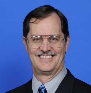
David P. Lindley PLS 5005
for a large PUD(Planned Unit Development) in Boca Raton called Boca Pointe. Dave and Jeff have been friends since they were 14 working together at a local Publix grocery store. After the Army, Dave and Jeff both began working for Caulfield & Wheeler in 1985 and still do to this day. One of Dave’s funniest memories with Jeff was a time they were both surveying a find site along the intercoastal waterway in Delray, FL. Jeff stepped on a log and a giant swarm of yellowjackets began attacking him. Dave knew his friend was allergic to them, so he rushed Jeff to the emergency room as quickly as he could. It wasn’t funny at the time Dave recalls, but because everything turned out ok, they can laugh about it now. There was another time Dave and Jeff were both surveying a railroad spur track for a commerce park. They had set a couple of hundred lathes the first day and when they went back the second day to grade them, lo and behold there was a pygmy rattlesnake at each stake.
Lindley graduated from Palm Beach Junior College with an Associate’s degree in surveying. He first started as an instrument operator and progressed to Party Chief for Caulfield & Wheeler until he got his professional surveyor’s license in 1991. That is when he took over as lead surveyor for the surveying operations and in 2008, Dave also began running the business side as Senior Vice President and Director of Surveying. When asked what his favorite thing about surveying is, he replies, “Every day is something new whether you work in the field, office or both. You go in thinking you are going to perform a certain task and it never works out that way. I also love the challenge of figuring out boundary problems and how prior surveyors made some interesting decisions. Honestly, my favorite memories are surveying mostly undeveloped south Florida with me and a couple of guys prior to the distractions of beepers, fax machines, modems, cell phones, and the internet. Those were great days.”
The largest surveying project Dave has worked on was in Port St. Lucie. The project was a PUD called “Tradition” and he was responsible for about 11,000 acres. When asked what his favorite type of survey is, he responds, “Boundary Survey because of the challenge of retracing a deed in the field. Every one is unique and many are very challenging, especially in the western part of Palm Beach and Martin county.” On what he feels has changed the most during his time in the profession, Lindley responds with, “The ability to access information on the internet from deeds, plats, LABINS(Land Boundary Information System), aerials, FDOT r/w maps and the speed at which you can complete a survey utilizing GPS. We also do a lot of airborne and mobile lidar which has changed everything in the way we approach and complete projects.”
The biggest hurdles Dave has encountered in the field are being self-taught
April 2023 Page 8
in land development, as well as platting in different municipalities, including their individual codes and regulations. Even though he believes it to be a pipe dream, one change he would like to see is for these municipalities to come up with a State standard for platting, (not in the lines of Chapter 177), and that there should be a uniform checklist. What has surprised him the most about the surveying profession, is “How many aspects of the work there are and the multiple ways of completing the work. I have been blessed to work with many fine surveyors during my career and all of them have taught me something; other ways to look at takes, or how they interpret a problem. Most notable was a surveyor named John Coates who I was privileged to work with for over 30 years and he definitelly taught me the most. His mentor was Bill Keith. I always remember him having a picture of him and Bill prominently displayed in his office. Unfortunately, John passed in May of 2022, and will be forever missed as he was the finest Boundary surveyor I have ever known.”

Mr. Lindley wanted to acknowledge certain fellow surveying professionals in the field that had an influence on him: Carl Purtz, Wes Haas, Robin Petzold (and all the instructors that assisted at PBJC), Donald Todd, and John Coates. The advice he would give to young surveyors is, “Get an education while working, doesn’t have to be college, could be seminars taught by other surveyors if you do not want to go down the licensure path. I have many unlicensed surveyors that work for us and they make a great living for not having a college degree and they enjoy the outdoor aspect of the profession. When you start out, go inside the office with the party chief to understand more about what you are doing and not just sit in the truck in the parking lot waiting for the chief to come out.”

new sponsorship opportunity! exhibit hall cash bar sponsorship Includes: • cash bar in the exhibit hall during friday's luncheon • company name & logo on Signage at luncheon • 4 drink tickets
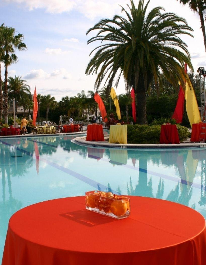
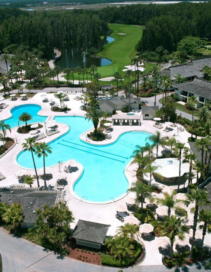
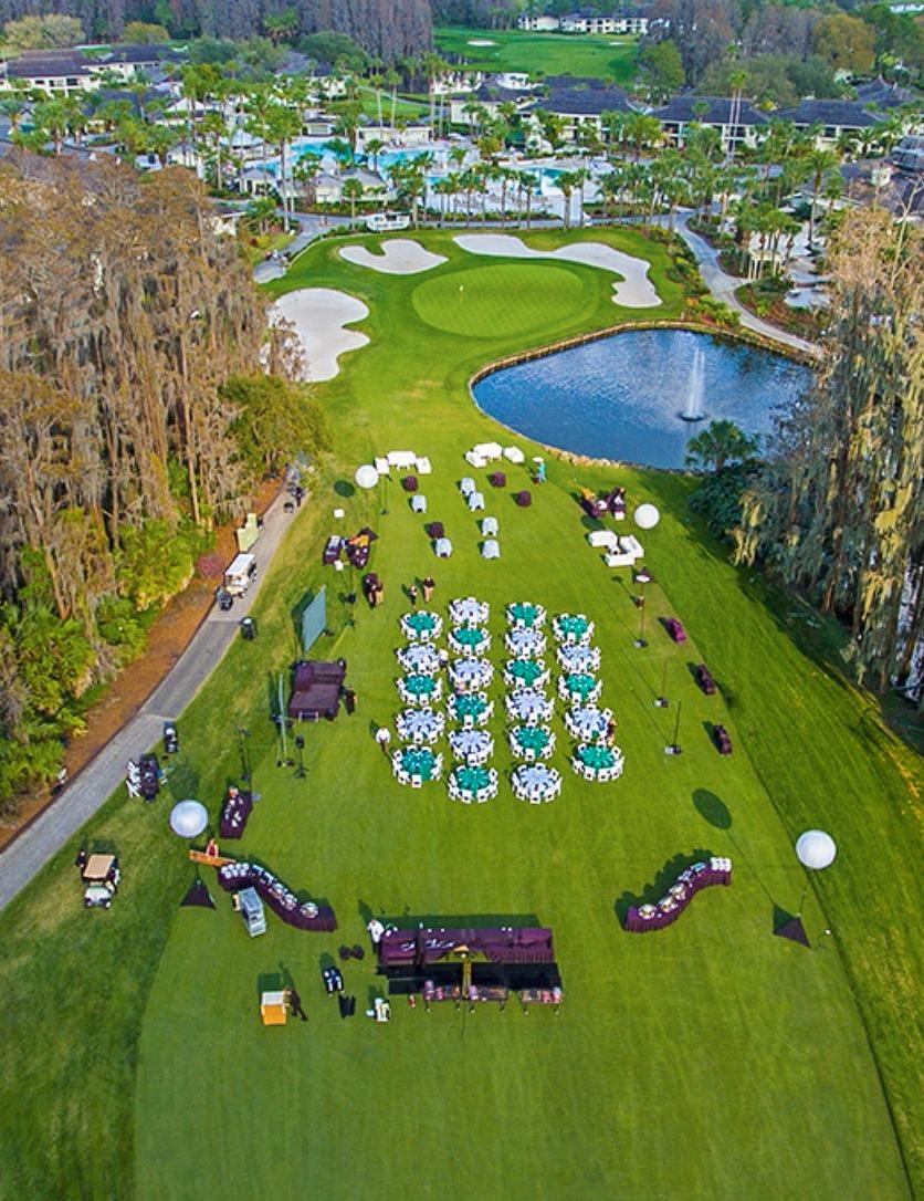
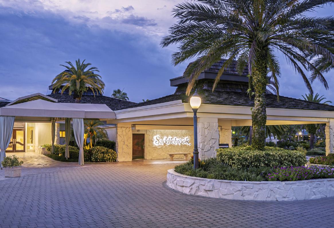
Make Plans to Attend the 68th Annual FSMS Conference
Make Plans to Attend the 68th Annual FSMS Conference
July 26th-29th at the Saddlebrook Resort in Wesley Chapel, FL.
July 26th-29th at the Saddlebrook Resort in Wesley Chapel, FL.


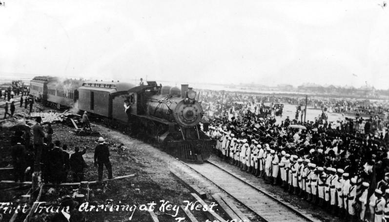
Florida East Coast Railway
In1912
Henry Flagler arrived aboard the first train into Key West, marking the completion of the Florida East Coast (FEC) Railway's OverSea Railroad to Key West. With the completion of the Over-Sea Railroad the entire east coast of Florida, from Jacksonville to Key West, was linked by a single railroad system. The FEC was the product of Flagler's resources and imagination. Flagler's construction of hotels at points along the railroad and his development of the agricultural industry through the Model Land Company established tourism and agriculture as Florida's major industries, which remain so even now more than a century later. In essence, Henry Flagler invented modern Florida.
 Courtesy of Henry Morrison Flagler Museum
The first passenger train, called Mr. Flagler’s Special, arriving at Key West on January 22, 1912. ©Flagler Museum Archives.
Courtesy of Henry Morrison Flagler Museum
The first passenger train, called Mr. Flagler’s Special, arriving at Key West on January 22, 1912. ©Flagler Museum Archives.
Amazingly, Flagler accomplished these feats after retiring from his first career and having reached an age equal to the average life expediency for an American male of the time. Flagler had co-founded Standard Oil with partners John D. Rockefeller and Samuel Andrews, long before becoming interested in Florida. Standard Oil remained the largest and most profitable corporation in the world for more than a century.
When Flagler first visited Florida in 1878, he recognized the state's potential for growth but noticed a lack of hotel facilities. Flagler returned to Florida, and in 1885 with an eye toward developing the area around St. Augustine, he began building a grand hotel, the Hotel Ponce de Leon. Flagler realized that the key to developing Florida was a solid transportation system and consequently purchased the Jacksonville, St. Augustine & Halifax Railroad. He also noticed that a major problem facing the existing Florida railway systems was that each operated on different gauge systems, making interconnection impossible.
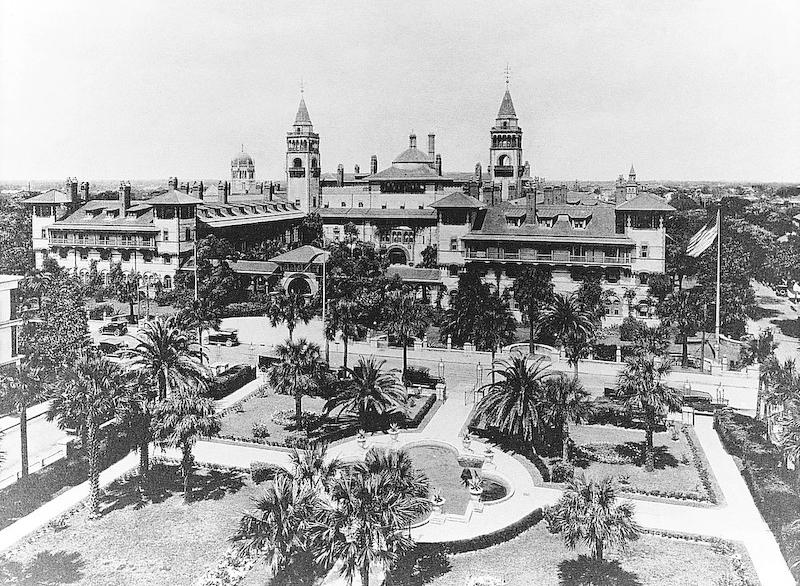 Historic photograph of Henry Flagler's first hotel, Hotel Ponce de Leon, in St. Augustine (now Flagler College). ©Flagler Museum Archives.
FSMS LEGISLATIVE NEWS... AND A REMINDER ABOUT PAC DUES

Greetings FSMS Members!
Following the amazing success of last year’s Legislative efforts, it’s once again time to prepare for the upcoming Florida Legislative Session (March 7 through May 5). Our Committees, Lobbyists and PAC are working hard to ensure strong relationships with our elected leaders.
Simply stated, without the actions, efforts and policies of the Florida Surveying and Mapping Society, our profession would have long ago been de-regulated. That’s a bold statement, but it is a fact, and if you wish to continue as a regulated profession, we must continue to build our membership and re-load our PAC.
Please consider investing in the future of your Profession through a contribution to the FSM PAC. (Link to Contribution Page)
The Officers of the Florida Surveyors and Mappers Political Action Committee (FSMPAC) are Jack Breed (Chair), David Daniel (Treasurer), John Clyatt, and Don Elder.

Your FSMS Legislative Committee: Jack Breed (chair), John Clyatt, Sam Hall, Russell Hyatt, Brian Murphy, Ray Niles, Chad Thurner, Don Elder, Leo Mills, Dodie Keith, Randy Tompkins and Howard Ehmke (ex officio).

Shortly after purchasing the Jacksonville, St. Augustine & Halifax Railroad, he converted the line to standard gauge.
The Jacksonville, St. Augustine & Halifax Railroad served the northeastern portion of the state and was the first railroad in what would eventually become the Florida East Coast Railway Company. In addition to improving the railroad, Flagler built schools, a hospital and churches in St. Augustine, systematically revitalizing the largely abandoned historic city.
Flagler soon purchased three more railroads: the St. John's Railway, the St. Augustine and Palatka Railway, and the St. Johns and Halifax Railroad so that he could provide extended rail service on standard gauge tracks. With the addition of these three railroads, by spring 1889 Flagler's system offered service from Jacksonville to Daytona. Continuing to develop hotel facilities to entice northern tourists to visit Florida, Flagler bought and expanded the Hotel Ormond, located along the railroad's route north of Daytona.
Beginning in 1892, when landowners south of Daytona petitioned him to extend the railroad 80 miles south, Flagler began laying new railroad tracks; no longer
FEC workers clear the roadbed before laying down rail tracks. ©Flagler Museum Archives.
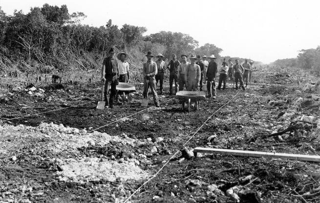
did he follow his traditional practice of purchasing existing railroads and merging them into his growing rail system. Flagler obtained a charter from the state of Florida authorizing him to build a railroad along the Indian River to Miami and as the railroad progressed southward, cities such as New Smyrna and Titusville began to develop along the tracks.
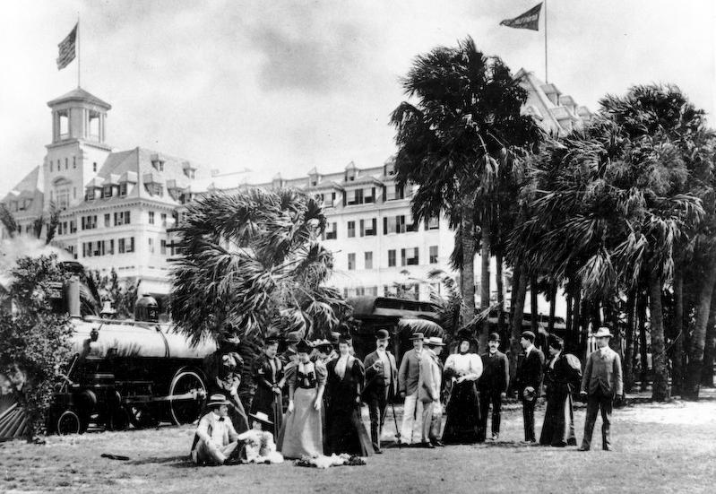
By 1894, Flagler's railroad system reached what is today known as West Palm Beach. Flagler constructed the Hotel Royal Poinciana on the eastern shore of Lake Worth in what is now known as Palm Beach. He also built The Breakers Hotel on the ocean side of Palm Beach, and Whitehall, his private 75-room, 100,000 square foot winter home. The building of the hotels, coupled with railroad access to them, established Palm Beach as a winter resort for the wealthy members of America's Gilded Age. The Hotel Royal Poinciana soon became the world’s largest resort.
Probably before he even extended his railroad to Daytona, Henry Flagler was seriously considering going all the way to Key West. However, he was content
The Florida Surveyor Page 15
Guests in front of Flagler's 1,150-room Hotel Royal Poinciana (demolished) in Palm Beach, 1886. ©Flagler Museum Archives.
LAND WATER
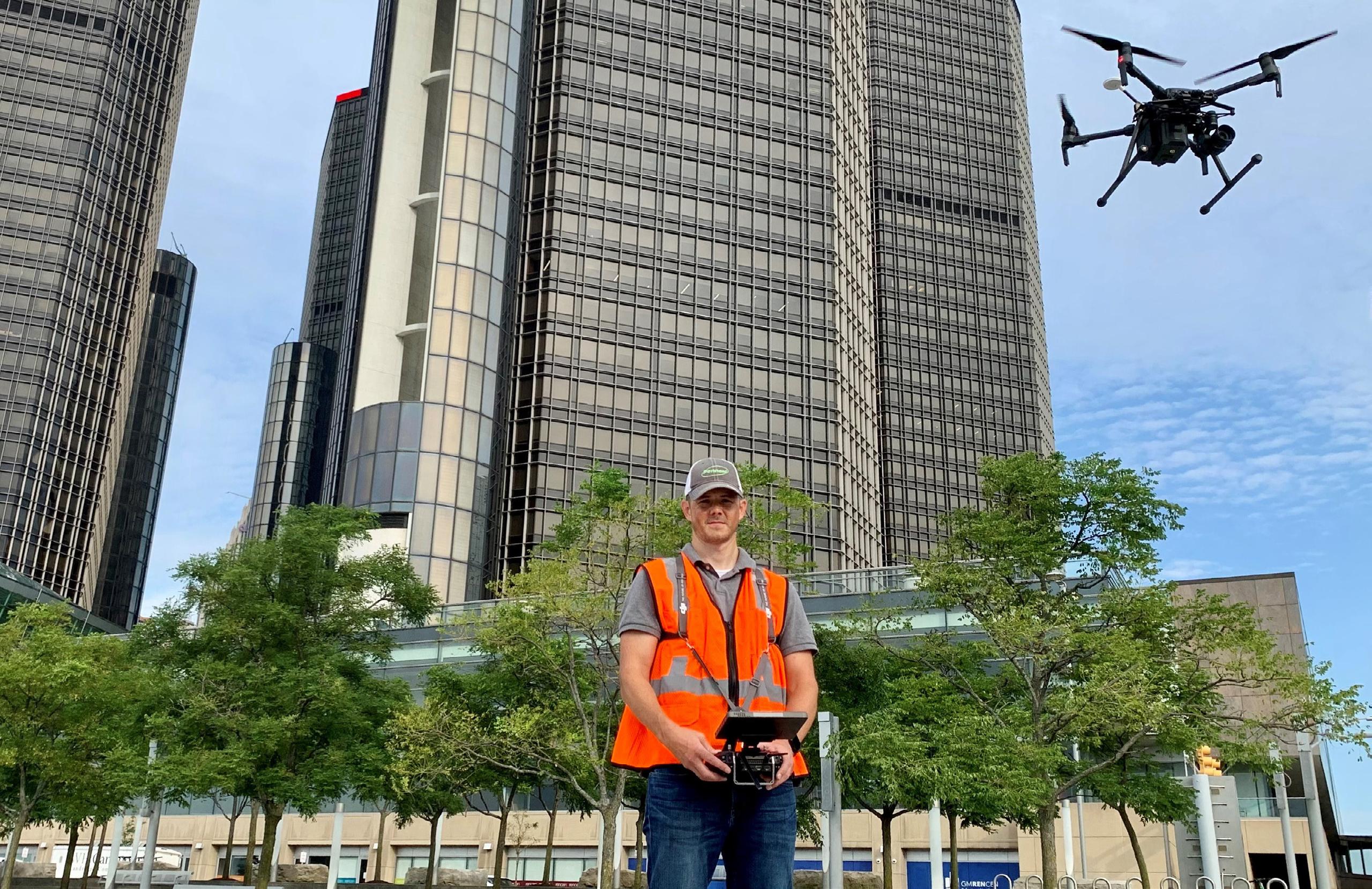
With the help of Frontier Precision, places you once couldn’t imagine measuring are now a daily reality. Frontier Precision leads the way in Unmanned technology – through the air, land, and underwater. Every place on earth is now reachable – with UAS from DJI, Autel, Parrot, Ascent, and ROVs, Pipe Crawlers, and Utility Crawler solutions from Deep Trekker. Count on us to deliver the latest technology to help you get your job done e ciently and accurately while driving your profits. Today, no mission is out of reach.


8301
FRONTIER PRECISION
JACKSONVILLE
|
Cyprus Plaza Drive,
FIND OU T M O RE A T : W W W .FRO N T IE RPRE C IS I ON.CO M / U N M A NN E D P R O DUCTS | T R AINING | RE PAIR | REN TA L S | T ECHNI C A L SE R VICE S AIR
#107 Jacksonville, FL 32256
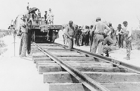
Workers lay rail tracks for the Florida East Coast Railway. ©Flagler Museum Archives.
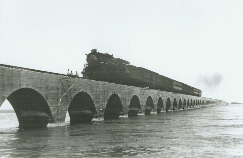
Florida East Coast Railway train crossing Long Key Viaduct. ©Flagler Museum Archives.
to wait for the right opportunity, which came as a result of the severe freezes of 1894 and 1895, which affected the state as far south as Palm Beach. To further convince Flagler to continue the railroad to Fort Dallas, he was offered land from private landowners, the Florida East Coast Canal and Transportation Company, and the Boston and Florida Atlantic Coast Land Company in exchange for laying track to Fort Dallas and that was enough to induce him to begin doing so immediately.
In September 1895, Flagler's system was incorporated as the Florida East Coast Railway Company and by 1896, it reached Biscayne Bay, the largest and most accessible harbor on Florida's east coast. To further develop the area surrounding the Fort Dallas railroad station, Flagler dredged a channel, built streets, instituted the first water and power systems, and financed the town's first newspaper, the Metropolis. When the town incorporated in 1896, its citizens wanted to honor the man responsible for the city's development by naming it, “Flagler.” He declined the honor, persuading them to use instead the native American name for the river running through the settlement, “Miama” or “Miami.”
April 2023 Page 18
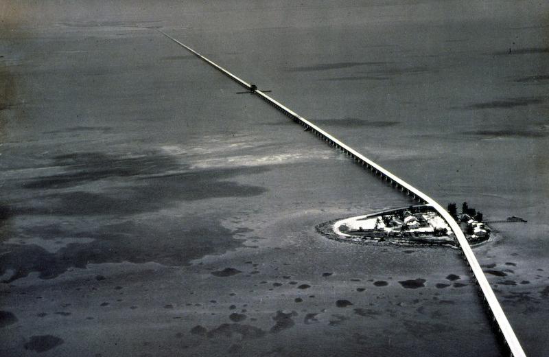
Aerial of FEC railroad through Pigeon Key. ©Flagler Museum Archives.
When the United States announced in 1905 its intention to build the Panama Canal, Flagler embarked on perhaps his greatest challenge: the extension of the Florida East Coast Railway to Key West, a city of almost 20,000 inhabitants located 128 miles beyond the end of the Florida peninsula. A train depot in Key West, the United States' closest deepwater port to the Canal, could not only take advantage of Cuban and Latin America trade, but significant trade possibilities with the west via the new Canal.

The construction of the Over-Sea Railroad required many engineering innovations as well as vast amounts of labor and monetary resources. The construction, employed up to four thousand men were. During the seven years of construction, five hurricanes threatened to halt the project with three causing major damage. Despite the hardships, and the engineering challenges, the OverSea Railroad, the final link of the Florida East Coast Railway, was completed on January 22, 1912, just weeks after Flagler’s 82nd birthday.
Linking the entire east coast of Florida with a transportation system and establishing tourism and agriculture as the basis of the state’s economy, at the
The Florida Surveyor Page 19
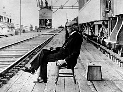
Historic candid photograph of Henry Flagler sitting at Knights Key. ©Flagler Museum Archives.
time was largely an uninhabited frontier, demanded a great deal of foresight and perseverance. More than a century later, the mainstays of Florida’s economy are still agriculture and tourism and Flagler’s incredible legacy as the inventor of modern Florida can still clearly be seen throughout Florida.
Join
• Civil/Site Design
• Construction Engineering
• Construction Materials Engineering & Testing
• Energy
• Environmental, Health, and Safety
• Geotechnical
• MEP
• Structural
• Survey & Geospatial
• Transportation
• Urban Planning & Design
• Water/Wastewater PARTNERS FOR WHAT’S
• Water Resources
www.pennoni.com

April 2023 Page 20
POSSIBLE
our Survey Team in Florida today!
round the State A
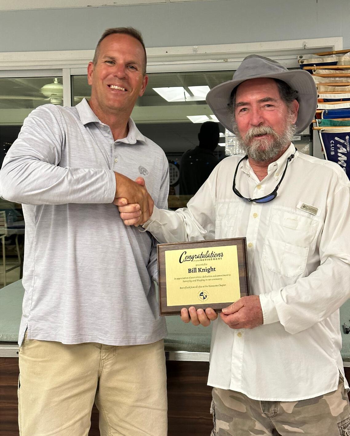
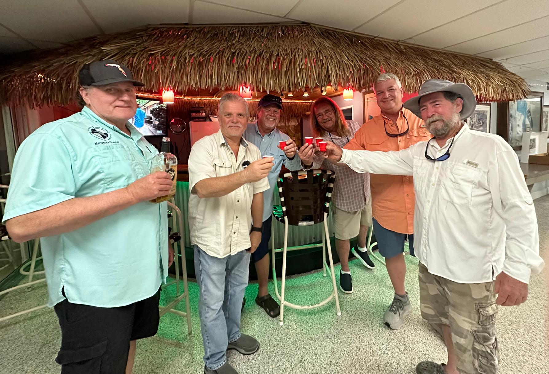
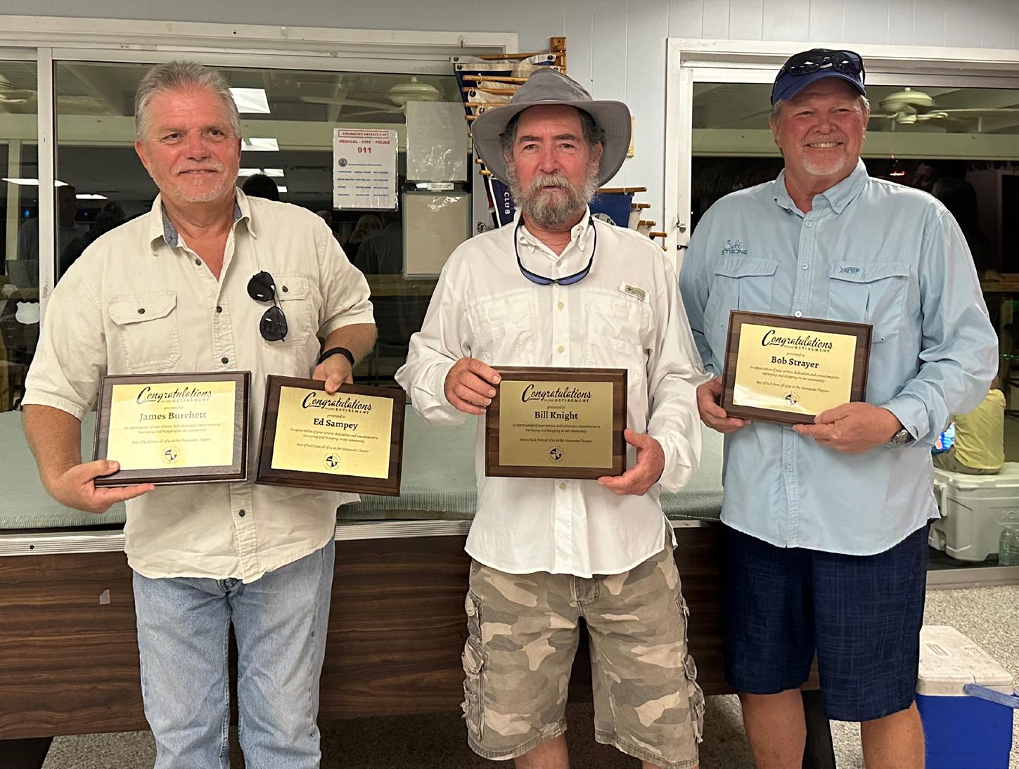
“ The Manasota Chapter a retirement party surveyors who will missed in our profession.
Bob Strayer (past director & BBQ extraordinaire), Billy Knight (BBQ and long time supporter our chapter), James Ed Sampey, and (past president of Chapter) have all in the Bradenton/Sarasota for decades and to see them leave, joyed that they will retirement to the We wish only the
The Florida Surveyor Page 21
Chapter hosted party for 5 local will be terribly profession. (past District 5 extraordinaire), (BBQ extraordinaire supporter of James Burchett, Mark Bassett of the Manasota all been surveying Bradenton/Sarasota area and we are sad leave, but overly will be enjoying the fullest! the best for them!
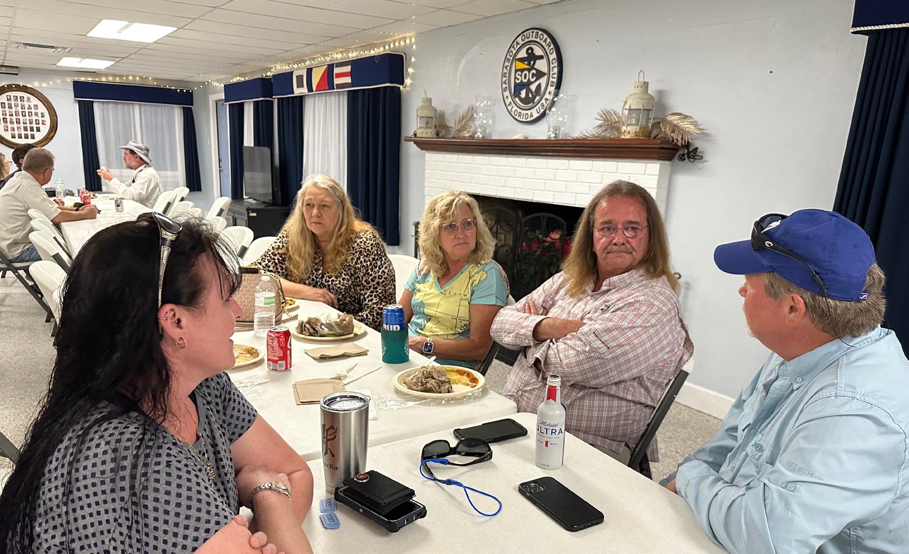
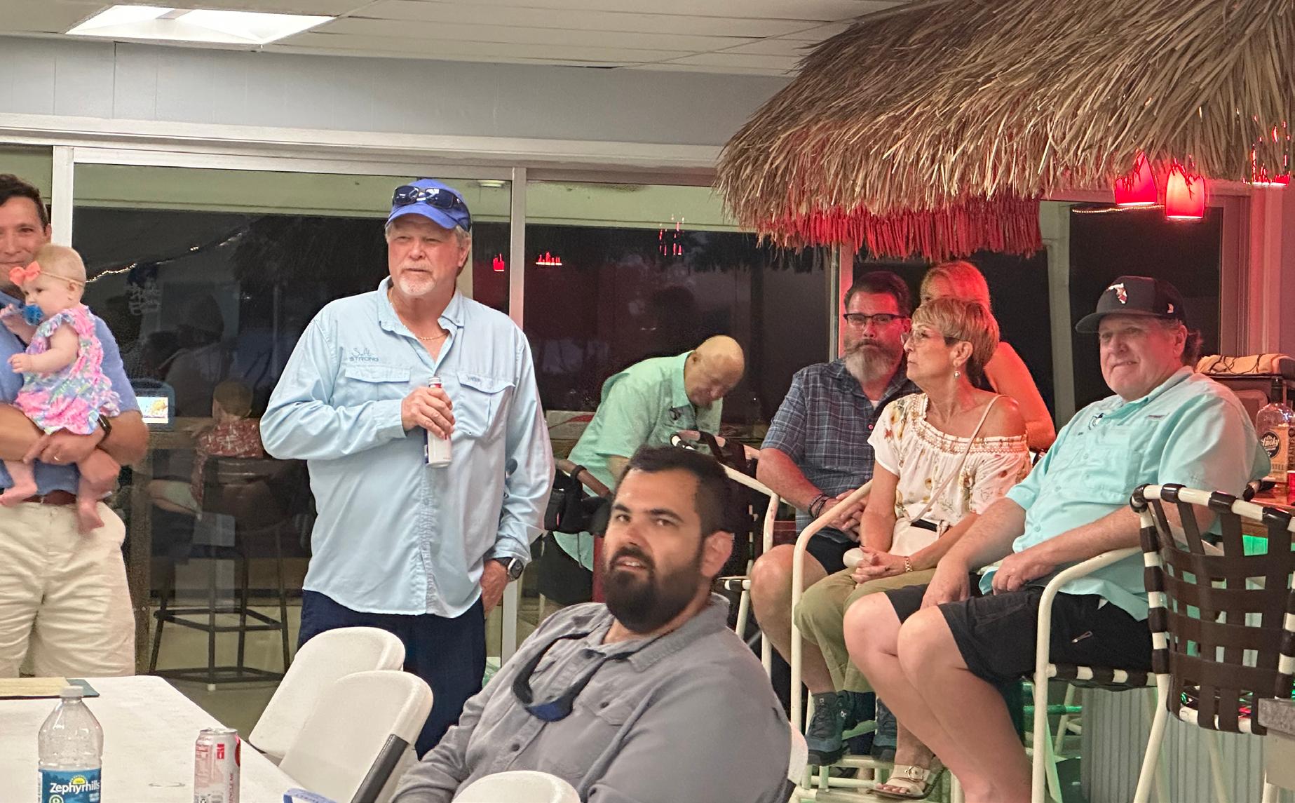
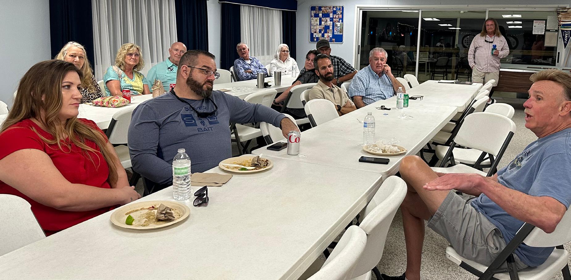
 - Pam Hyatt
”
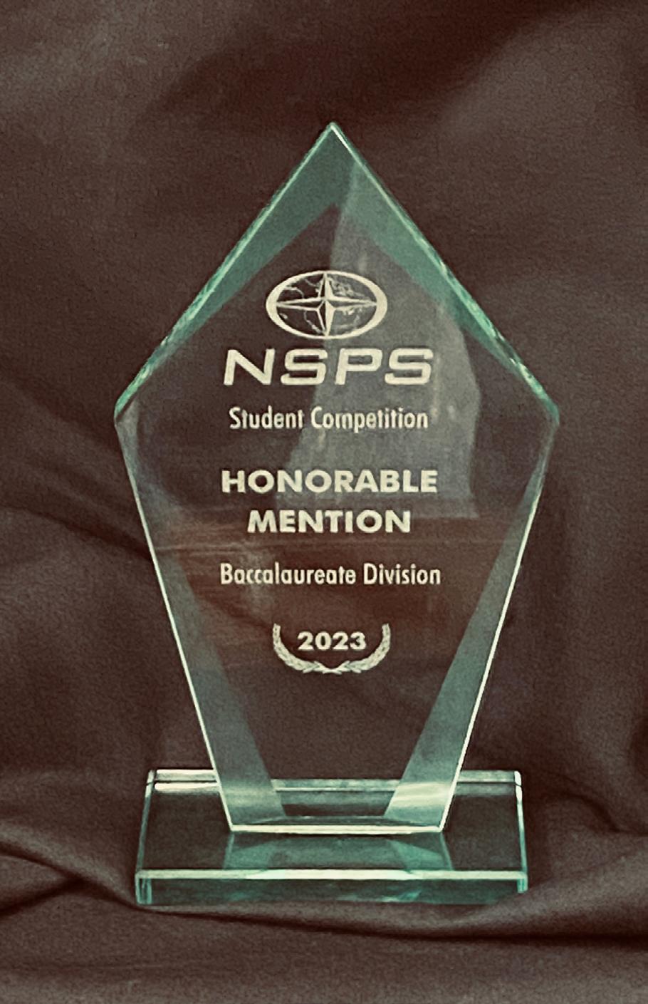
2023 NSPS YSN (Young Surveyors Network) Student Competition
Student
2023 NSPS YSN (Young Surveyors Network)
Competition
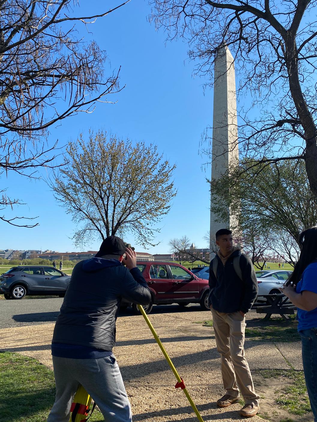
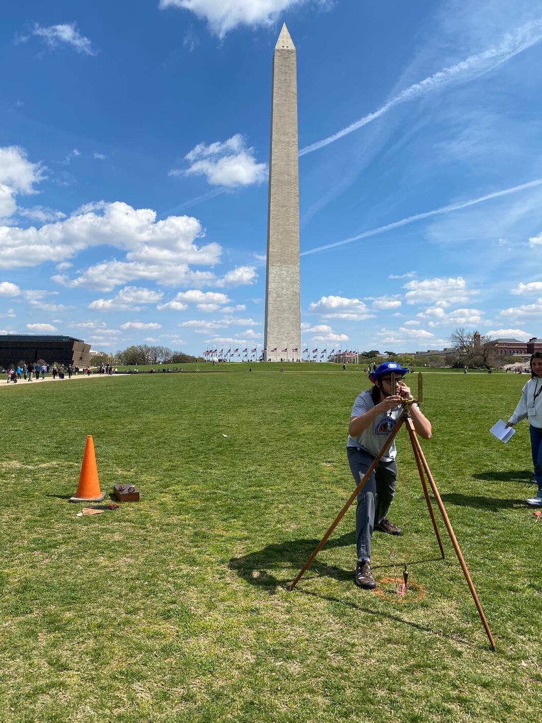
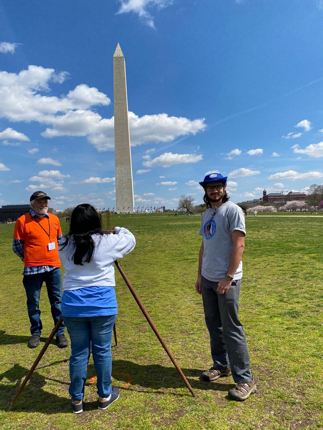
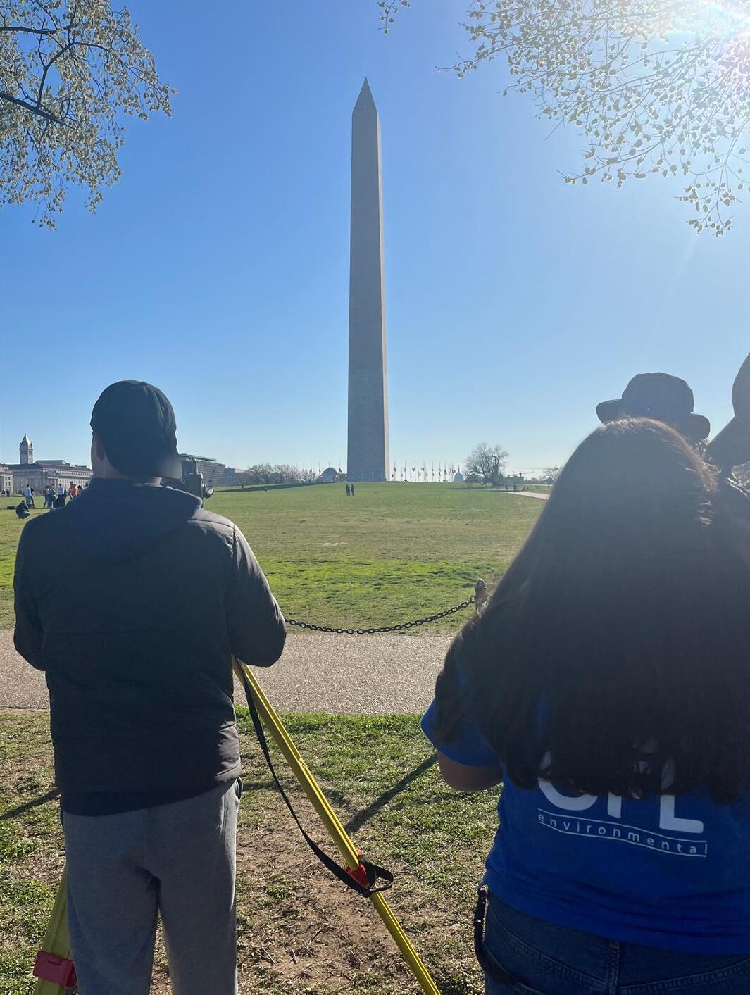
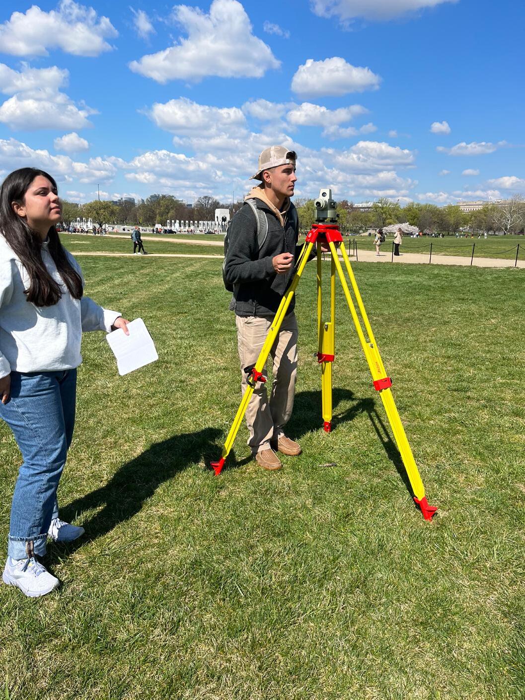
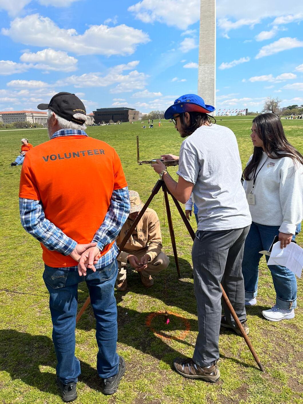
UF Students Gabe Hancock and Kenneth Dell work with a T2 Manual Theodolite to sight the Washington National monument. UF Geomatics Student Kenneth Dell preparing to sight the Washington National Monument.
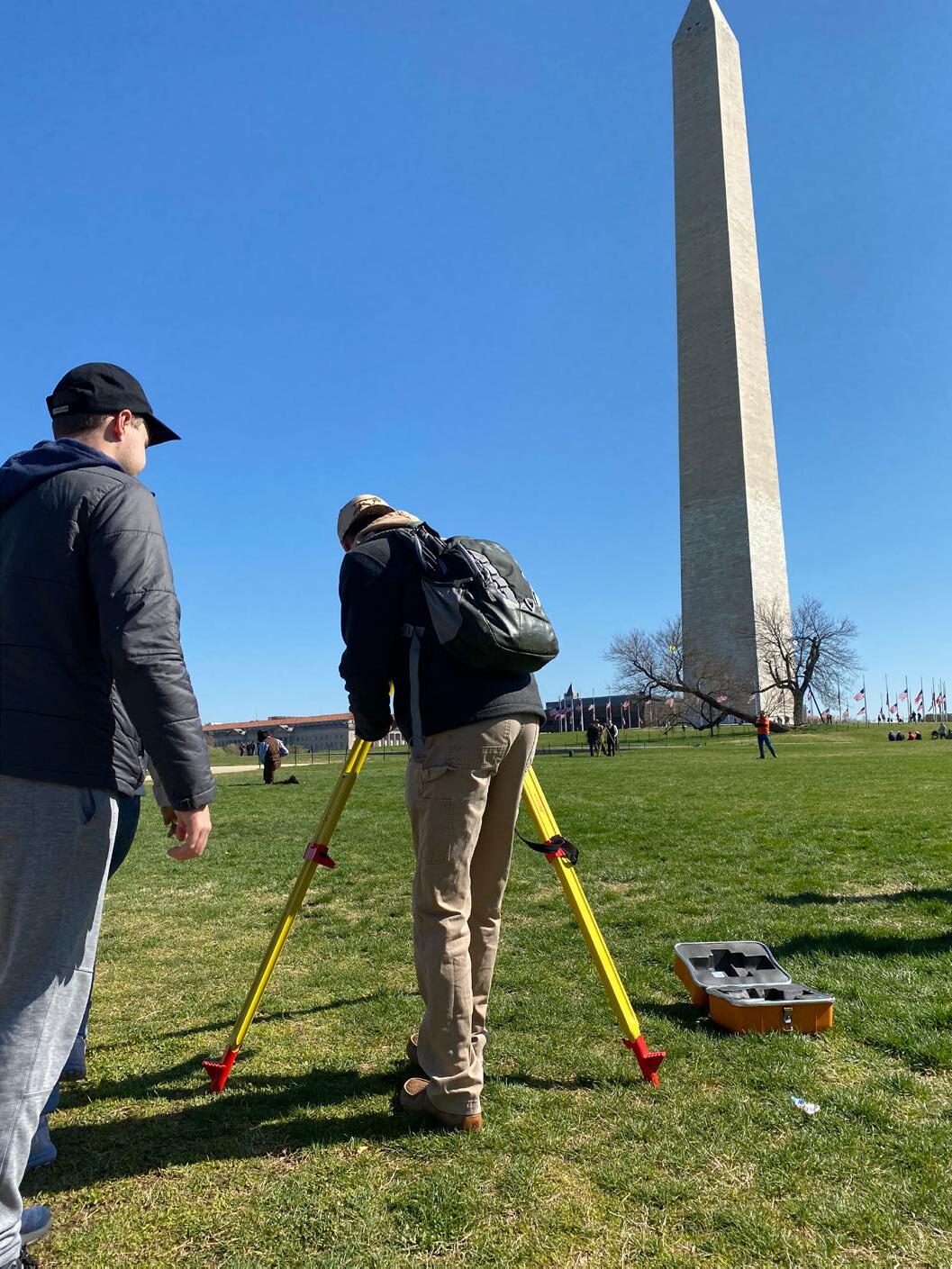
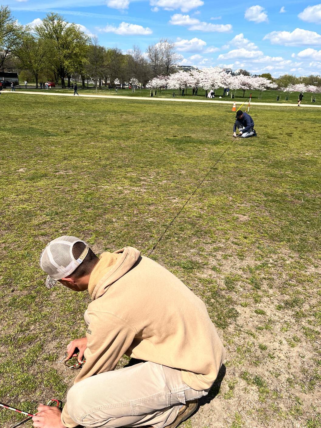
UF Geomatics Students Gabe Hancock and Isabel Dupee working together on the 3-wire leveling field activity on the National Mall.
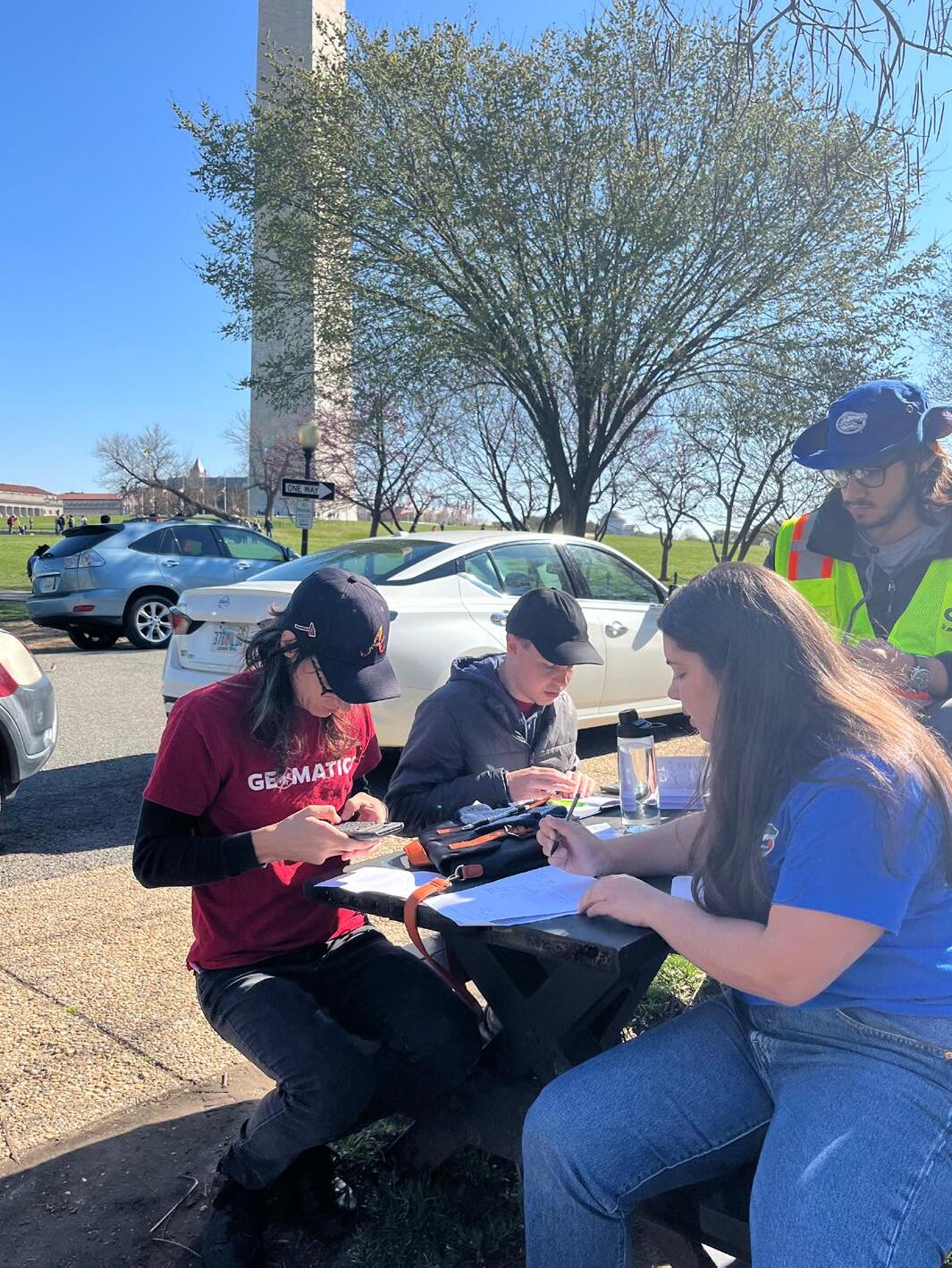
UF Students Andrea Slaven, Isabel Dupee, Kenneth Dell and Jacob Suarez work on reducing field notes to compute the coordinates of the “unknown point.”
UF Geomatics Students Gabe Hancock and Kenneth Dell working with a 33’ Gunter’s Chain and Chaining Pins to measure the sides of the parcel in the Geometric Traverse problem.
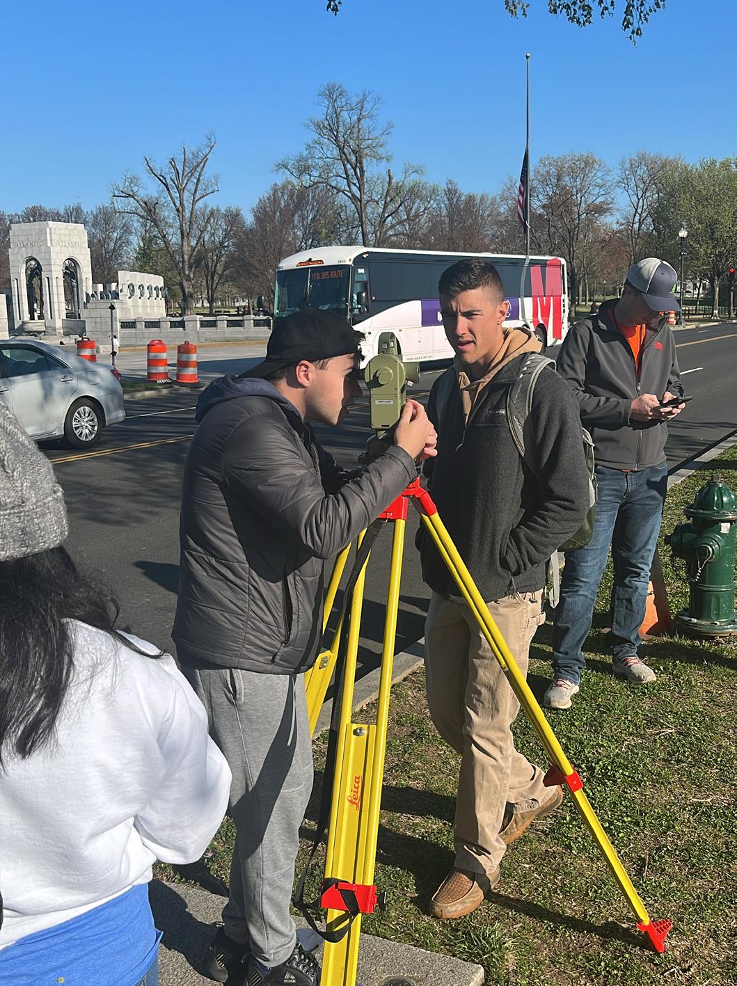
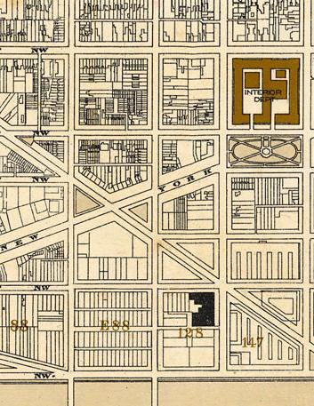
solve the Geometric Traverse problem, located on the National Mall, just south of the Washington National Monument.
2023 NSPS YSN (Young Surveyors Network) Student Competition
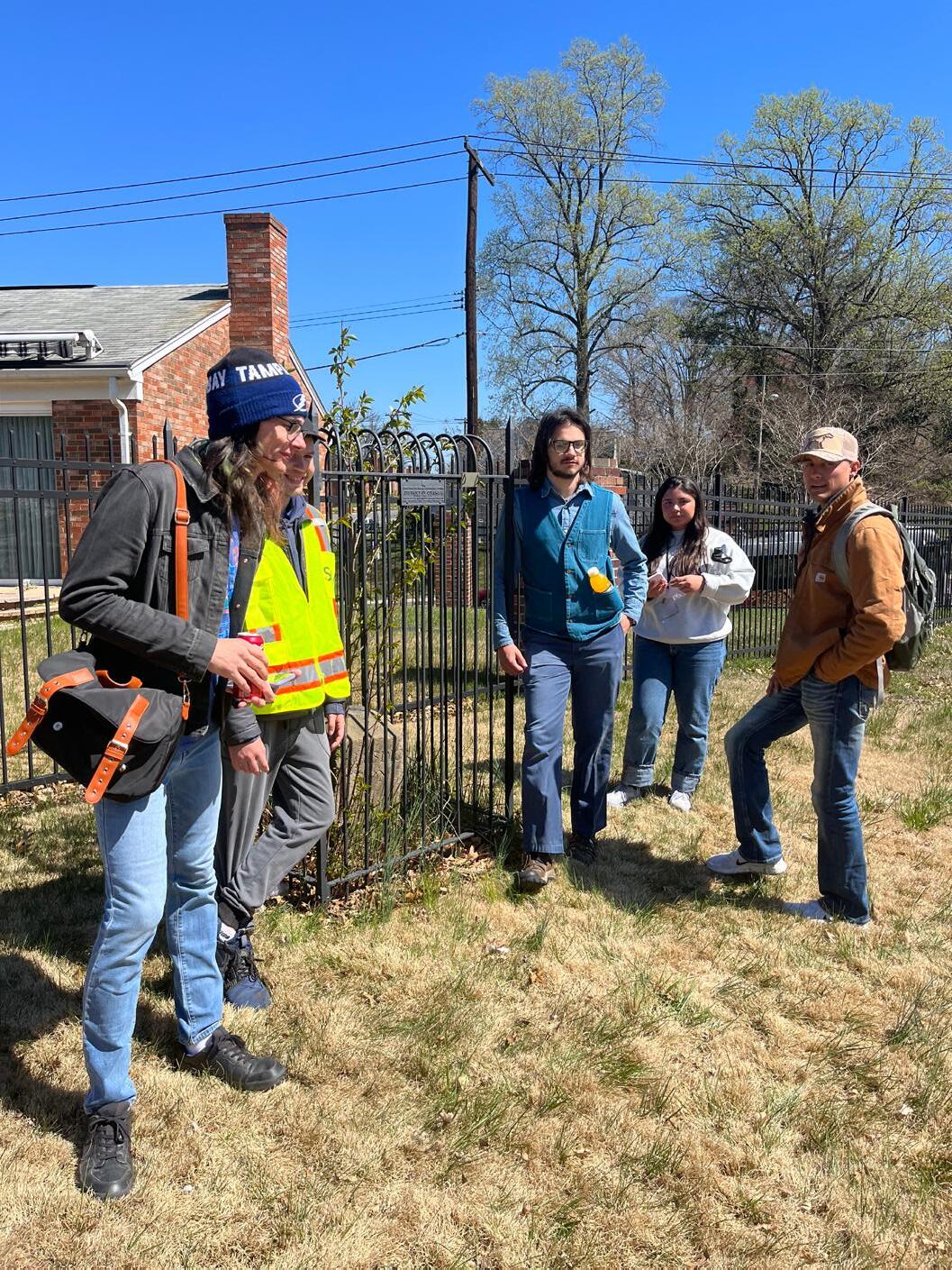
 UF Geomatics Students Jacob Suarez, Gabe Hancock and Isabel Dupee working with a compass to
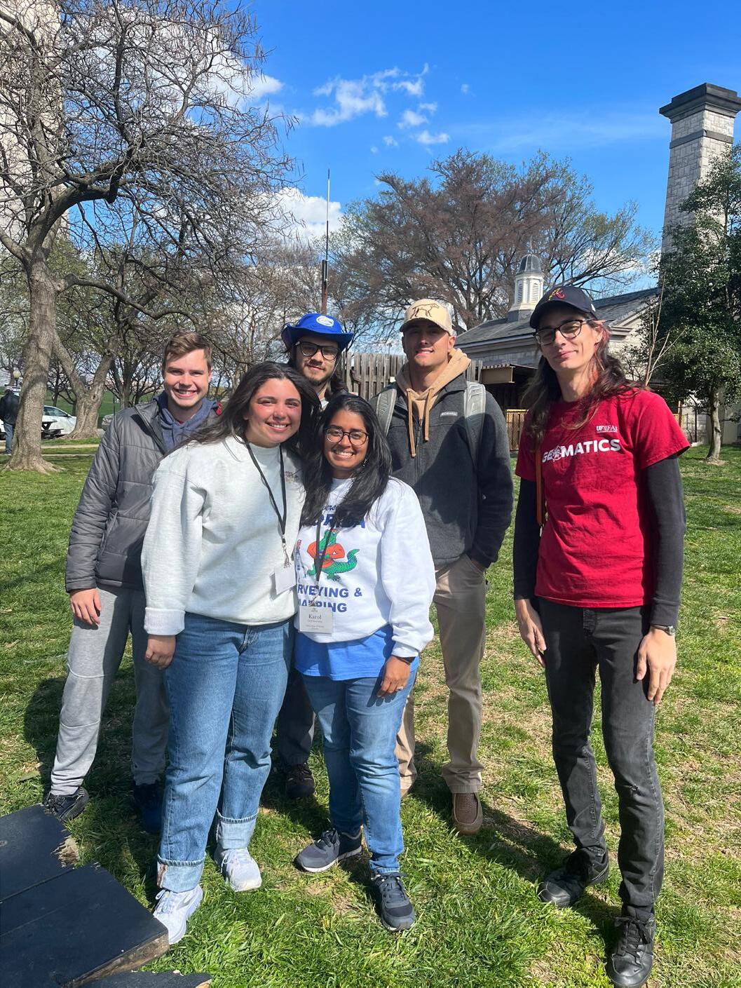
UF Geomatics Students, [(Back Row, Left to Right) Kenneth Dell, Jacob Suarez, Gabe Hancock, Andrea Slaven]; [(Front Row, Left to Right) Isabel Dupee, Karol Hernandez], after day 1 of the competition.
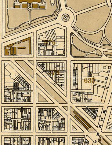
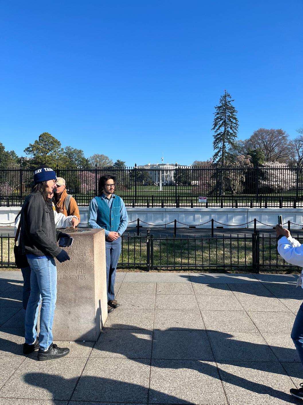
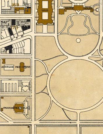
UF Geomatics Students Andrea Slaven, Jacob Suarez, Gabe Hancock, standing at the Zero Mile Stone (NGS PID: HV1847) in front of the White House during the 6-hr NGS Monument Hunt.
UF Geomatics Students Jacob Suarez, Gabe Hancock and Isabel Dupee working with a compass to
UF Geomatics Students, [(Back Row, Left to Right) Kenneth Dell, Jacob Suarez, Gabe Hancock, Andrea Slaven]; [(Front Row, Left to Right) Isabel Dupee, Karol Hernandez], after day 1 of the competition.
UF Geomatics Students Andrea Slaven, Jacob Suarez, Gabe Hancock, standing at the Zero Mile Stone (NGS PID: HV1847) in front of the White House during the 6-hr NGS Monument Hunt.
UF Geomatics Students, Andrea Slaven, Kenneth Dell and Isabel Dupee standing next to the NE3 Washington DC Boundary stone set by Benjamin Banneker circa 1791.
UF
Students, Andrea Slaven, Kenneth Dell, Jacob Suarez, Isabel Dupee and Gabe Hancock standing next to the NE2 Washington DC Boundary stone set by Benjamin Banneker circa 1791.
2023 NSPS YSN (Young Surveyors Network) Student Competition
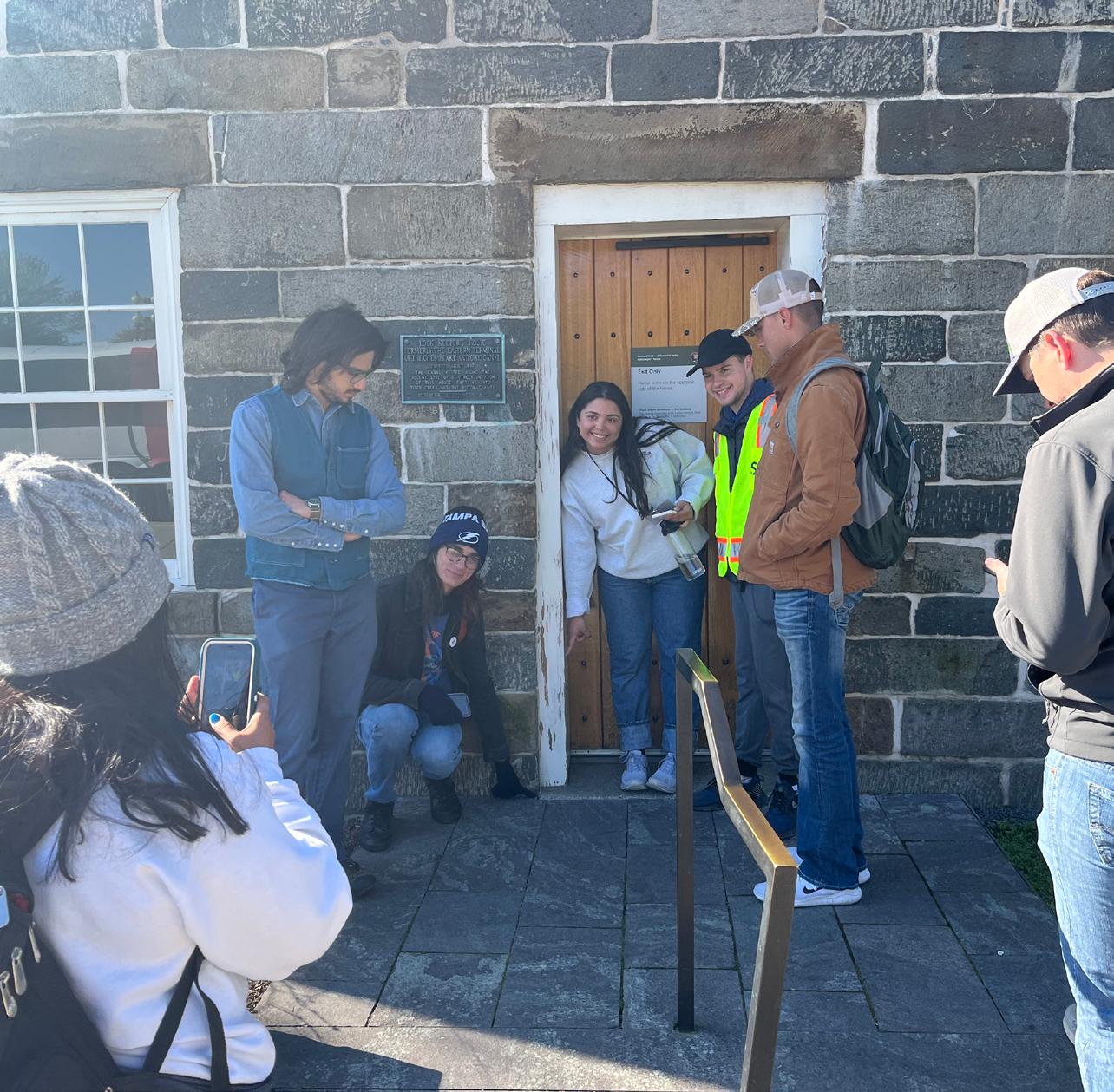
Karol Hernandez, Jacob Suarez, Andrea Slaven, Isabel Dupee, Kenneth Dell, and Gabe Hancock, standing at the Lock Keepers House (NGS PID: HV1851) during the 6-hr NGS Monument Hunt.
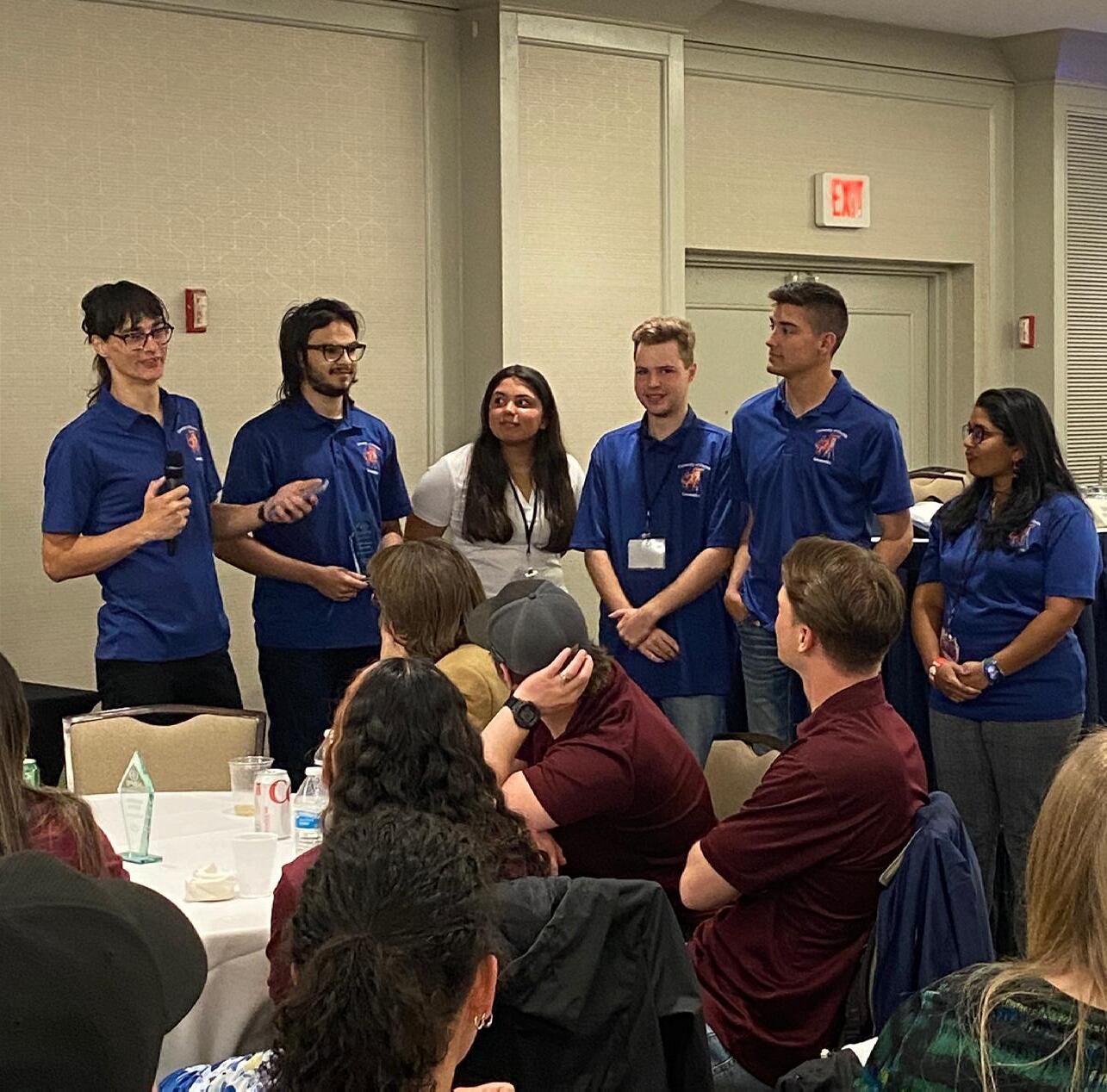
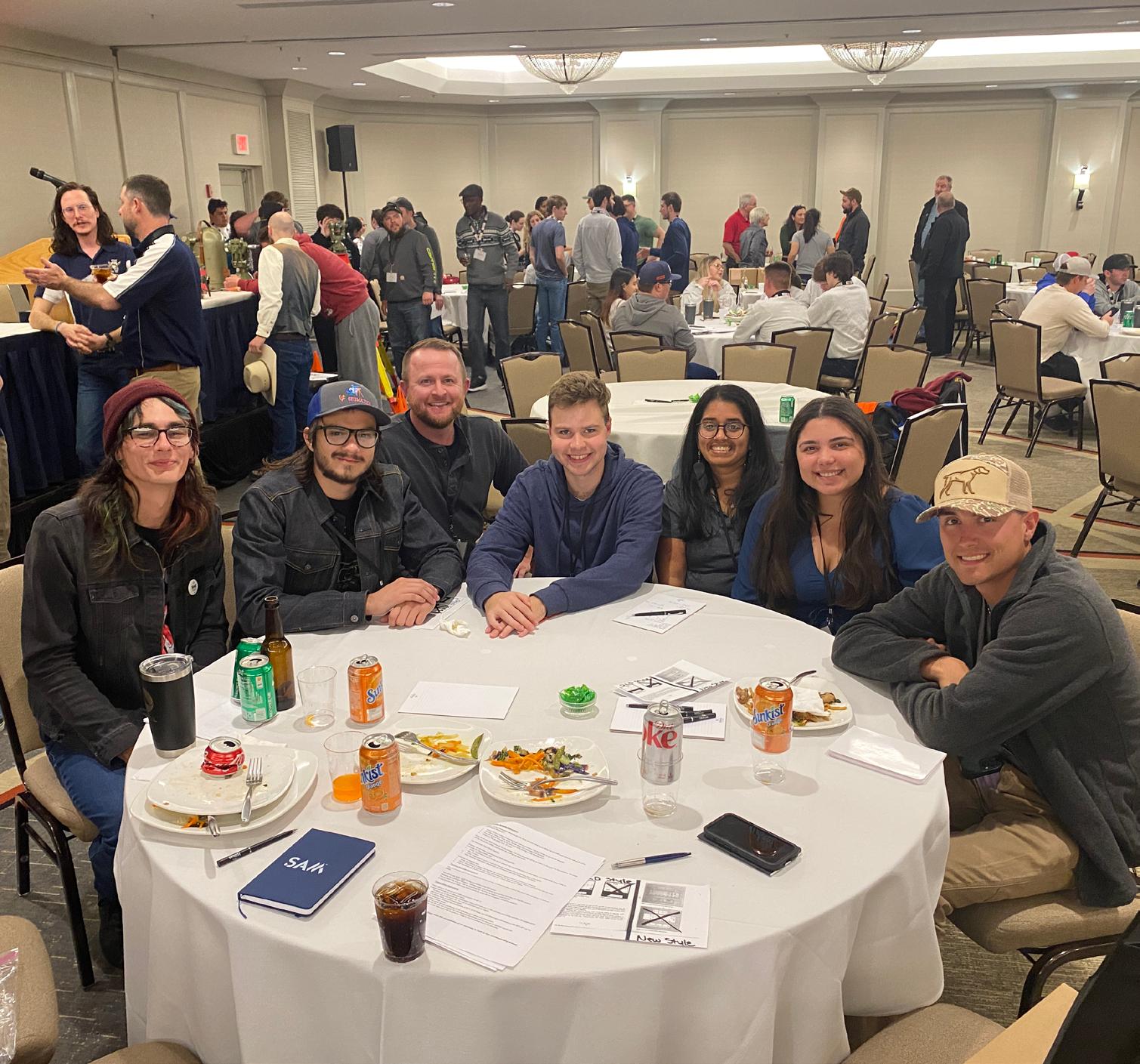
Awards Luncheon at the 2023 NSPS YSN Student Competition.
 UF Geomatics Students (Left to Right)
UF Geomatics Students (From left to right) Andrea Slaven, Jacob Suarez, Isabel Dupee, Kenneth Dell, Gabe Hancock, and Karol Hernandez receiving their Award during the
Geomatics
UF Geomatics Students (Left to Right)
UF Geomatics Students (From left to right) Andrea Slaven, Jacob Suarez, Isabel Dupee, Kenneth Dell, Gabe Hancock, and Karol Hernandez receiving their Award during the
Geomatics
2023 NSPS YSN (Young Surveyors Network) Student Competition
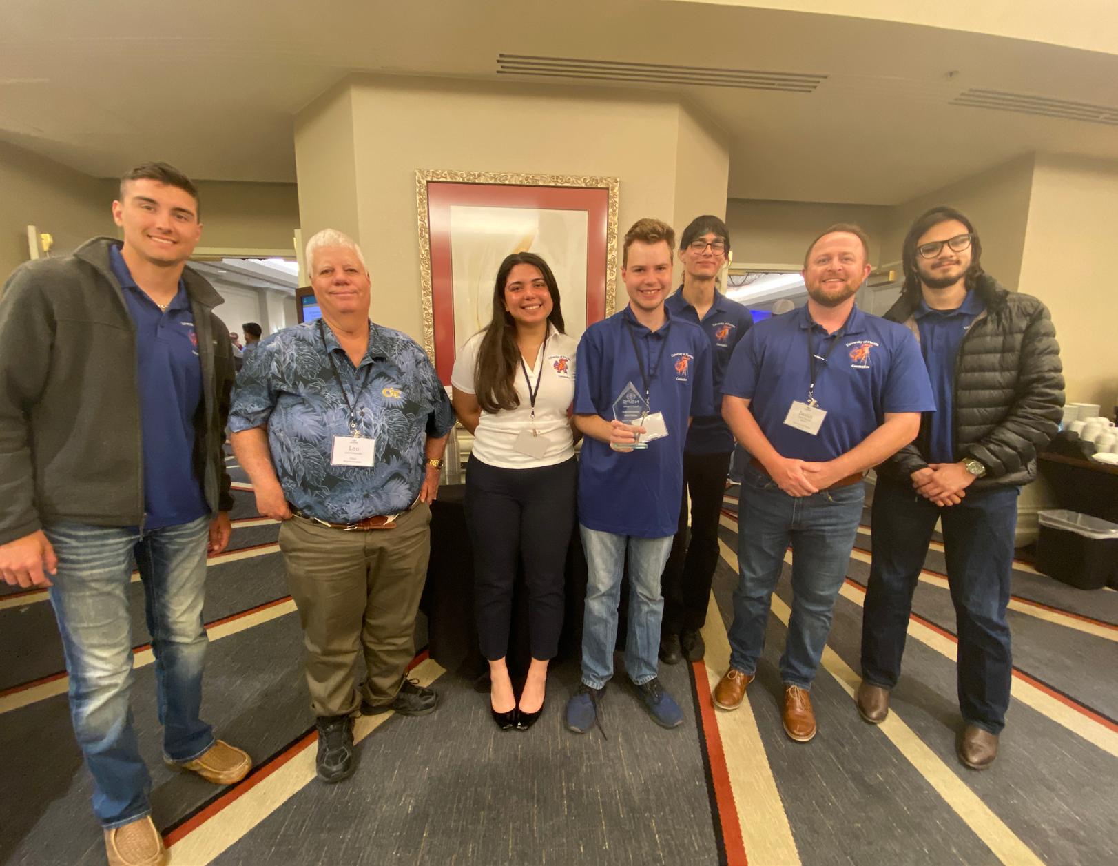
 UF Geomatics Students with past FSMS President Lou Campanile, Jr. holding their Award during the Awards Luncheon.
UF Geomatics Students (L to R)Andrea Slaven, Jacob Suarez, Justin Thomas P.S.M.(faculty), Kenneth Dell, Karol Hernandez, Isabel Dupee and Gabe Hancock during the Awards Luncheon.
UF Geomatics Students with past FSMS President Lou Campanile, Jr. holding their Award during the Awards Luncheon.
UF Geomatics Students (L to R)Andrea Slaven, Jacob Suarez, Justin Thomas P.S.M.(faculty), Kenneth Dell, Karol Hernandez, Isabel Dupee and Gabe Hancock during the Awards Luncheon.
202 3 S u S taining
3002 Surveying 352-538-1320
Ardurra, Inc. 239-292-7773
Associated Land Surveying & Mapping, Inc. 407-869-5002

Bello & Bello Land Surveying Corporation 305-251-9606
A. D. Platt & Associates, Inc. 850-329-5551
Agnoli, Barber & Brundage, Inc. 239-597-3111
AIM Engineering & Surveying 239-332-4569
Allen & Company, Inc. 407-654-5355
Allen Engineering 321-783-7443 American Surveying, Inc. 813-234-0103
Amerritt, Inc. 813-221-5200
Arc Surveying & Mapping, Inc. 904-384-8377
Atwell, LLC 866-850-4200
Avirom & Associates, Inc. 561-392-2594
Axis Geospatial, LLC 410-822-1441
Benchmark Surveying & Land Planning, Inc. 850-994-4882
Bennett-Panfil, Inc. 941-497-1290
Berntsen International 608-443-2772
Betsy Lindsay, Inc. 772-286-5753
Biscayne Engineering Company, Inc. 305-324-7671
Banks Engineering 239-939-5490
Barnes, Ferland and Associates, Inc. 407-896-8608
Barraco & Associates, Inc. 239-461-3170
Bartram Trail Surveying, Inc. 904-284-2224
Boatwright Land Surveyors, Inc. 904-241-8550
Bock & Clark Corporation(NV5) 330-665-4821
Bowman Consulting Group 703-454-1000
Bradshaw-Niles & Associates, Inc. 904-829-2591
Brown & Phillips, Inc. 561-615-3988
BSE Consultants, Inc. 321-725-3674
Buchanan & Harper, Inc. 850-763-7427
Calvin, Giordano & Associates, Inc. 954-921-7781
Carlson Environmental Consultants, PC 704-283-9765
Carnahan, Proctor & Cross, Inc. 407-960-5980
Carter Associates, Inc. 772-562-4191
A
B
C
F irm S Directory
DSW Surveying & Mapping, PLC. 352-735-3796

(Causseaux,
CivilSurv
Clements
Coastal
Collins
Cousins
CPH
Craven-Thompson
D DeGrove
Caulfield & Wheeler 561-392-1991 Chastain-Skillman, Inc. 863-646-1402 CHW Professional Consultants
Hewett & Walpole, Inc.) 352-331-1976
Design Group, Inc. 863-646-4771
Surveying, Inc. 941-729-6690 Clymer Farner Barley Surveying, Inc. 352-748-3126
Engineering Associates, Inc. 352-796-9423 Colliers Engineering & Design 732-383-1950
Survey Consulting, LLC. 863-606-2155
Surveyors & Associates, Inc. 954-689-7766
Consulting, LLC 407-322-6841
& Associates, Inc. 954-739-6400 Culpepper & Terpening, Inc. 772-464-3537 Cumbey & Fair, Inc. 727-797-8982
Surveyors, Inc. 904-722-0400 Dennis J. Leavy & Associates 561-753-0650
DMK Associates, Inc. 941-412-1293 Donald W. McIntosh Associates, Inc. 407-644-4068 Donoghue Construction Layout, LLC. 321-248-7979 Douglass, Leavy & Associates, Inc. 954-344-7994 DRMP, Inc. 833-811-3767 DroneView Technologies 248-321-9417
E ECHO
Eiland
904-272-1000 Element
813-386-2101 Engenuity
Engineering
Construction,
ER
ETM
Duncan-Parnell, Inc. 800-849-7708 Durden Surveying and Mapping, Inc. 904-853-6822
UES, Inc. 888-778-3246 Eda Consultants, Inc. 352-373-3541
& Associates, Inc.
Engineering Group, LLC.
Group, Inc. 561-655-1151
Design &
Inc. 772-462-2455
Brownell & Associates, Inc. 305-860-3866
Suryeying & Mapping 904-642-8550
Exacta Land Surveyors, Inc. 866-735-1916 EXP Energy Services Inc. 305-213-9969 F Ferguson Land Surveyors 727-230-9606 First Choice Surveying, Inc. 407-951-3425 Florida Design Consultants, Inc. 727-849-7588 Florida Engineering & Surveying, LLC. 941-485-3100 FLT Geosystems 954-763-5300 Ford, Armenteros & Fernandez, Inc. 305-477-6472 Fortin, Leavey, Skiles, Inc. 305-653-4493 Frontier Precision Unmanned 701-222-2030 F.R.S. & Associates, Inc. 561-478-7178 G GCY, Inc. 772-286-8083 GeoData Consultants, Inc 407-732-6965 Geoline Surveying 386-418-0500 Geomatics Corporation 904-824-3086 Geo Networking, Inc. 407-549-5075 GeoPoint Surveying, Inc. 813-248-8888 George F. Young 727-822-4317 Geosurv, LLC 877-407-3734 Germaine Surveying, Inc. 863-385-6856 GPI Geospatial, Inc. 407-851-7880 Gustin, Cothern & Tucker, Inc. 850-678-5141 H Haley Ward, Inc. 207-989-4824 Hanson Professional Services, Inc. 217-788-2450 Hanson, Walter & Associates, Inc. 407-847-9433 H.L. Bennett & Associates, Inc. 863-675-8882 Hole Montes, Inc. 239-254-2000 HUB International 850-386-1111 Hyatt Survey Services 941-748-4693 I Ibarra Land Surveyors 305-262-0400 I.F. Rooks & Associates, LLC. 813-752-2113 J John Mella & Associates, Inc. 813-232-9441 Johnston’s Surveying, Inc. 407-847-2179 K KCI Technologies 954-776-1616 Keith and Associates, Inc. 954-788-3400 202 3 S u S taining
F irm S Directory
Kendrick Land Surveying, LLC 863-533-4874 L L&S Diversified, LLC. 407-681-3836 Land Precision Corporation 727-796-2737 Landmark Engineering & Surveying Corporation 813-621-7841 Langan Engineering and Environmental Services, Inc. 973-560-4900 Leading Edge Land Services, Inc. 407-351-6730 Leiter Perez & Associates, Inc. 305-652-5133 Lengemann Corp. 800-342-9238 Leo Mills & Associates 941-722-2460 Long Surveying, Inc. 407-330-9717 M Manuel G. Vera & Associates, Inc. 305-221-6210 Massey-Richards Surveying & Mapping, LLC. 305-853-0066 Masteller, Moler & Taylor, Inc. 772-564-8050 McKim & Creed, Inc. 919-233-8091 McLaughlin Engineering, Co. 954-763-7611 Metron Surveying and Mapping, LLC. 239-275-8575 Mock Roos & Associates, Inc. 561-683-3113 Moore Bass Consulting, Inc. 850-222-5678 Morris-Depew Associates, Inc. 239-337-3993 Murphy’s Land Surveying 727-347-8740 N Navigation Electronics, Inc. 337-237-1413 Northwest Surveying, Inc. 813-889-9236 NV5 - Technical Engineering & Consulting Solutions 954-495-2112 O On The Mark Surveying, LLC. 321-626-6376 P PEC Surveying & Mapping 407-542-4967 Pennoni Associates, Inc. 863-594-2007 Perret and Associates, Inc 904-805-0030 Pickett & Associates, Inc. 863-533-9095 Platinum Surveying & Mapping, LLC. 863-904-4699 Point Break Surveying 941-378-4797
Polaris Associates, Inc. 727-461-6113 Porter Geographical Positioning & Surveying, Inc. 863-853-1496 Pulice Land Surveyors, Inc. 954-572-1777 Q Q Grady Minor & Associates, PA 239-947-1144 R Reece & White Land Surveying, Inc. 305-872-1348 Rhodes & Rhodes Land Surveying, Inc. 239-405-8166 Richard P. Clarson & Associates, Inc. 904-396-2623 R.J. Rhodes Engineering, Inc. 941-924-1600 R.M. Barrineau & Associates, Inc. 352-622-3133 Robayna and Associates, Inc. 305-823-9316 S SAM Surveying & Mapping, LLC. 850-385-1179 SCR & Associates NWFL Inc. 850-527-1910 Sergio Redondo & Associates, Inc. 305-378-4443 Settimio Consulting Services, Inc. 850-341-0507 SGC Engineering, LLC. 407-637-2588 Shah Drotos & Associates, PA 954-943-9433 Sherco, Inc. 863-453-4113 Sliger & Associates, Inc. 386-761-5385 Southeastern Surveying & Mapping Corp. 407-292-8580 Stephen H. Gibbs Land Surveyors, Inc. 954-923-7666 Stoner Inc. 954-585-0997 Surveying & Mapping Inc. 239-340-2409 SurvTech Solutions, Inc. 813-621-4929 T T2 UES Inc. 407-587-0603 Tectonic Engineering and Surveying Consultants 845-534-5959 Thurman Roddenberry & Associates 850-962-2538 TranSystems Corporation Consultants 727-822-4151 U UF/IFAS School of Forest, Fisheries, and Geomatics Sciences 352-846-0850 Upham, Inc. 386-672-9515 W Wade Surveying, Inc. 352-753-6511 202 3 S u S taining
F irm S Directory
Wallace Surveying Corp.
561-640-4551
Wantman Group, Inc.(WGI)
561-687-2220
WBQ Design & Engineering, Inc. 407-839-4300
Whidden Surveying
561-790-5515
Winnigham & Fradley, Inc. 954-771-7440
Woolpert, Inc. 803-214-5928 Z
ZNS Engineering, LLC. 941-748-8080
SOCIAL MEDIA LINKS

LinkedIn = 408 Followers
Facebook = 786 Followers
Twitter = 407 Followers
Instagram = 165 Followers
YouTube
Proclamations from National Surveyors Week
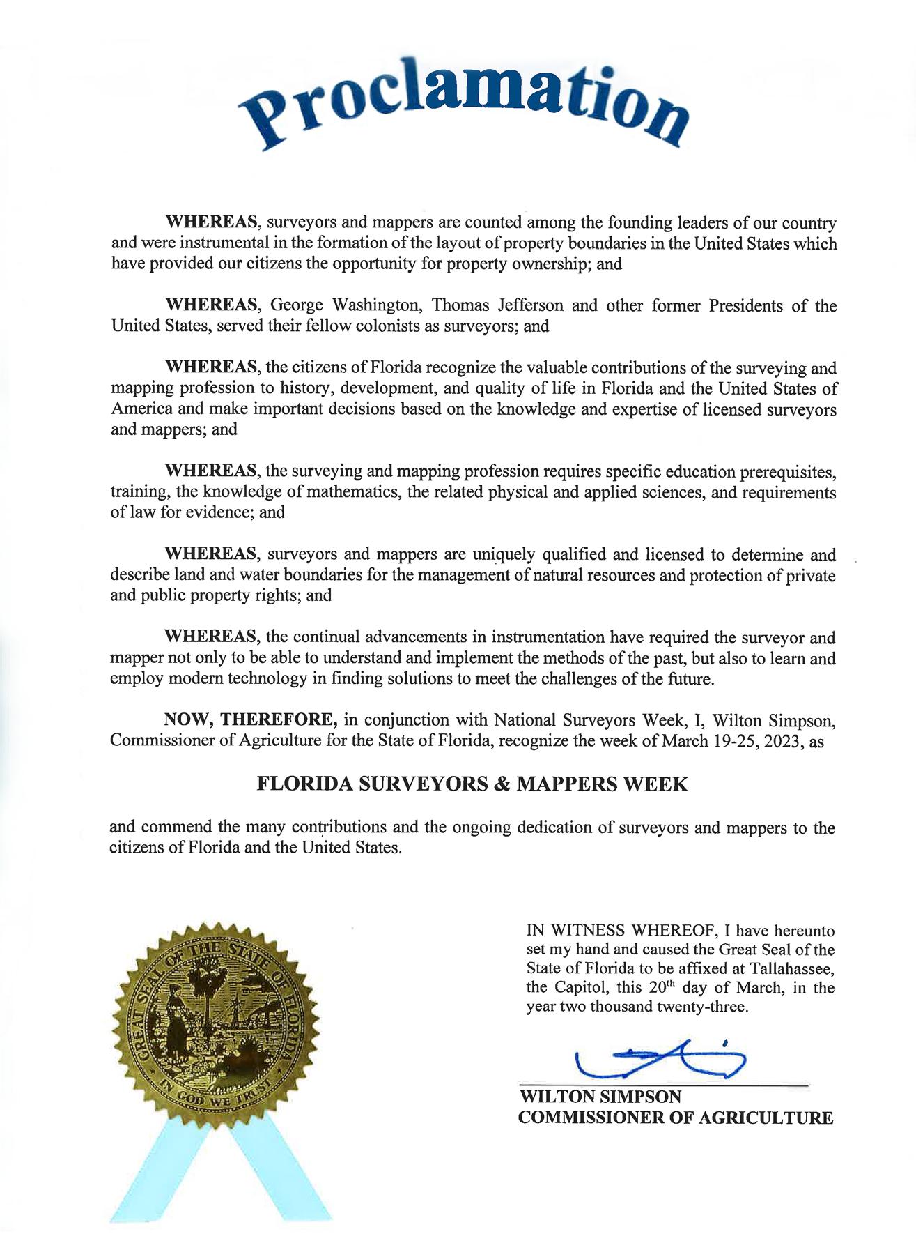
March 19–25, 2023

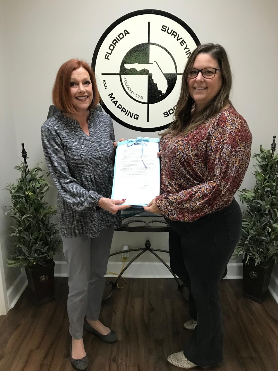
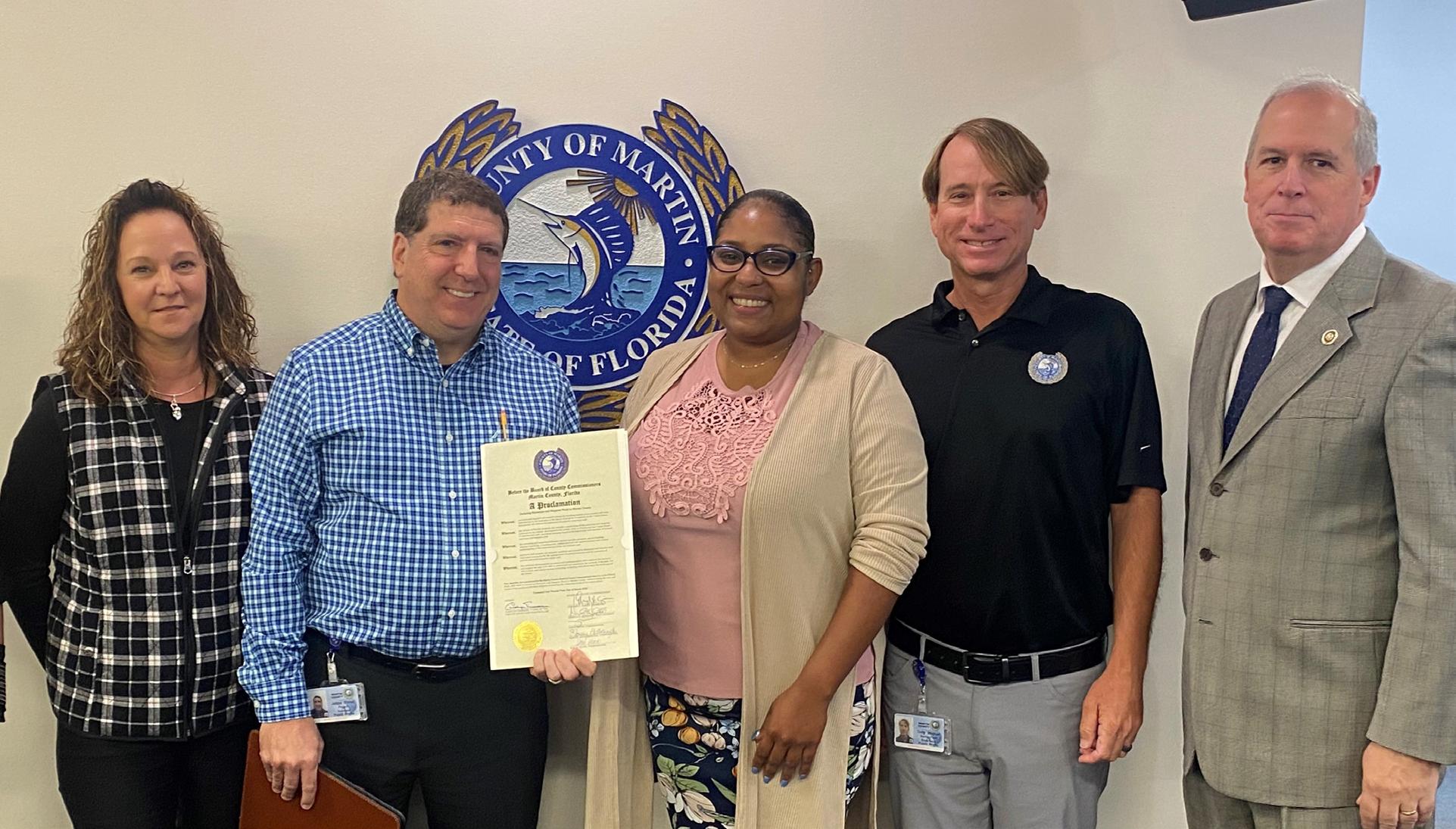
BPSM Executive Director Liz Compton (left) presents this year's Florida Surveyors & Mappers Week Proclamation to Executive Director of FSMS, Rebecca Porter.
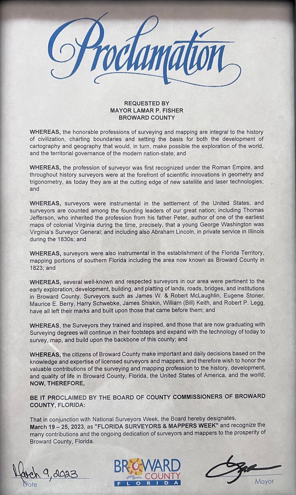
Broward County

The Florida Surveyor Page 36
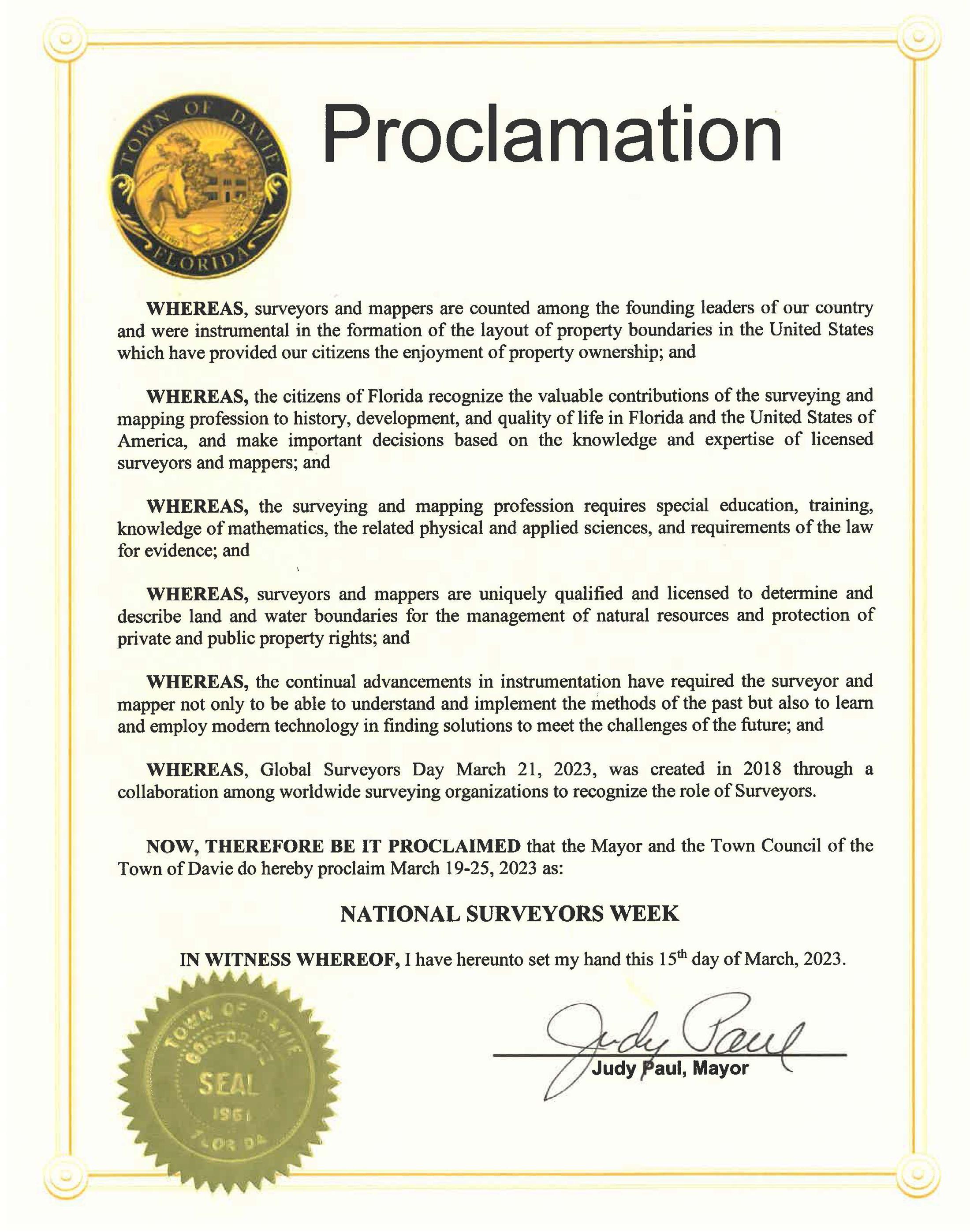
Town of Davie
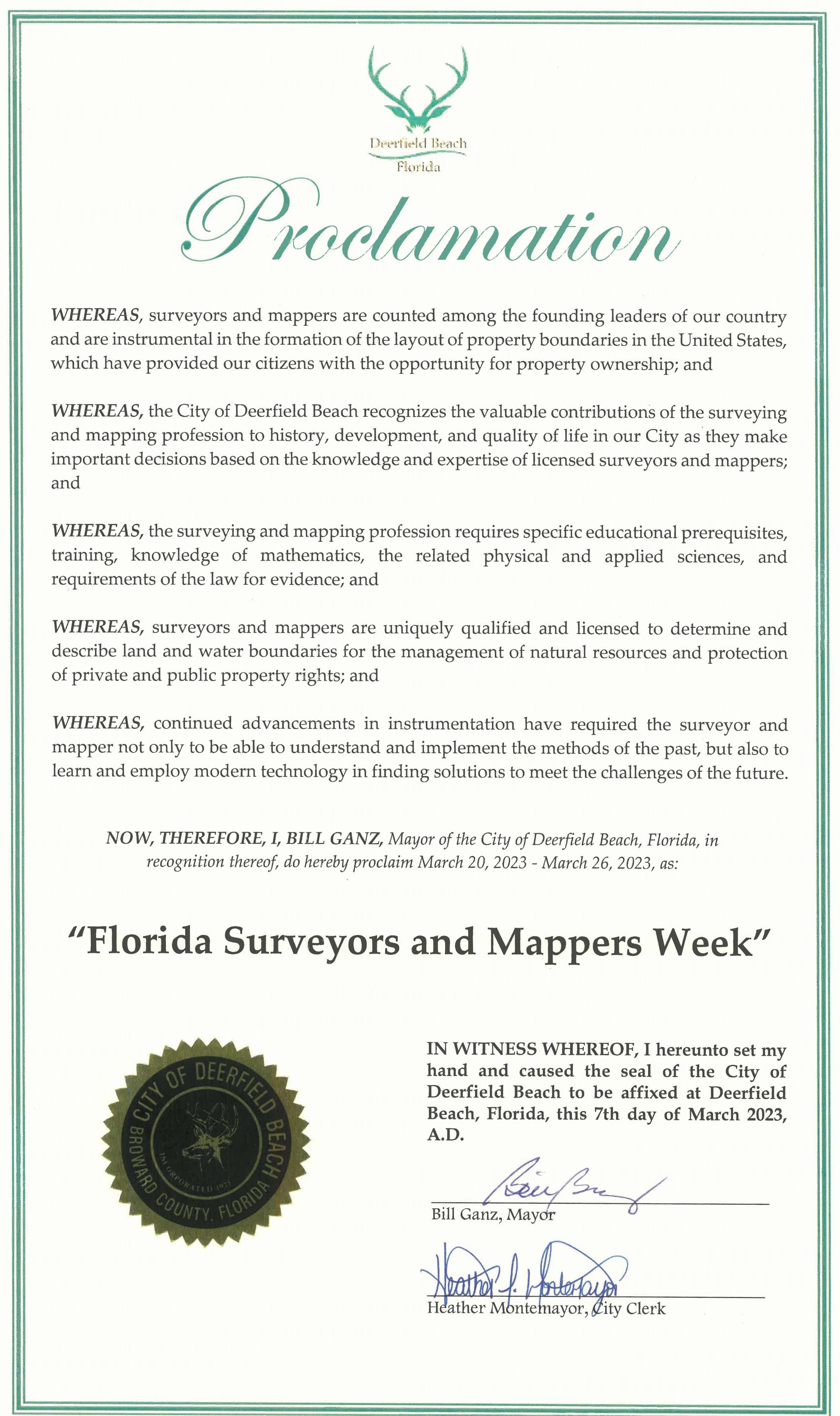
City of Deerfield Beach
The Florida Surveyor Page 38
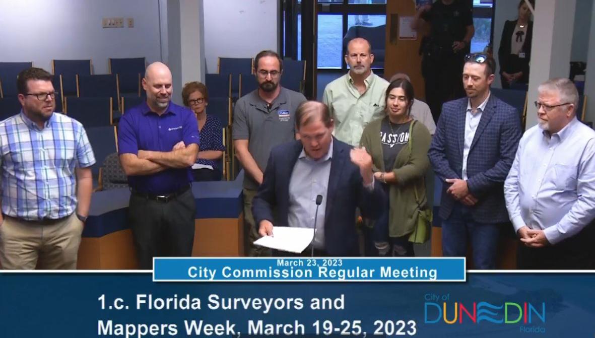
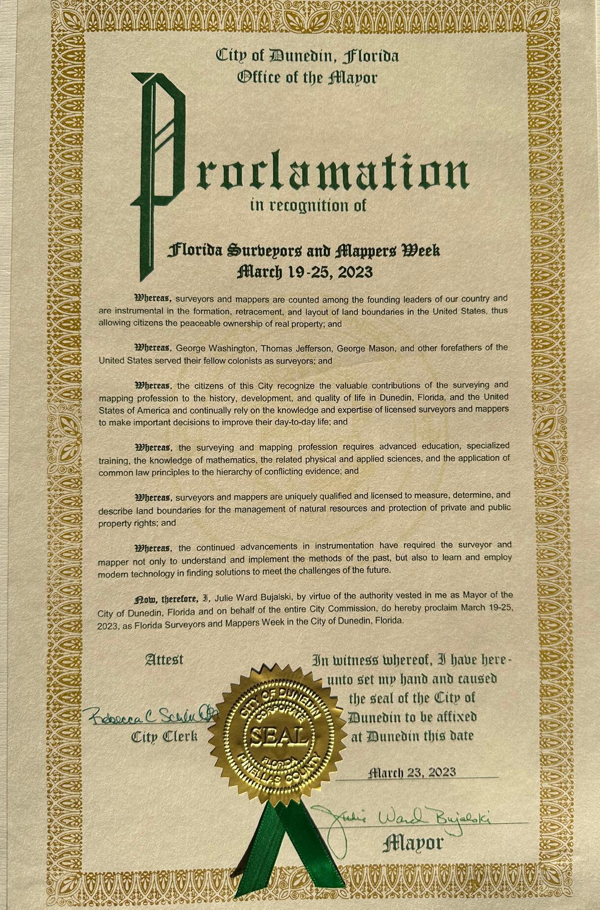
City of Dunedin
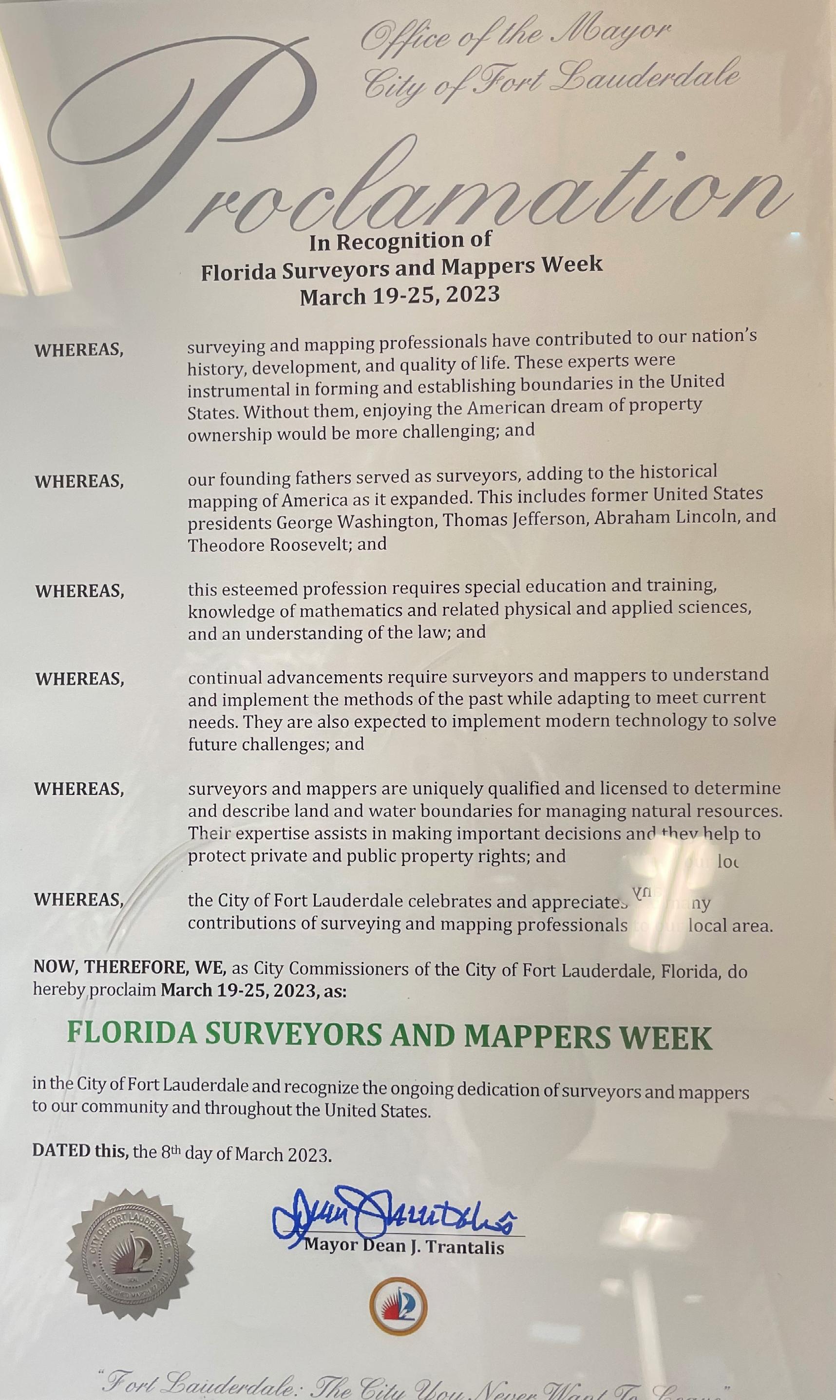
City of Fort Lauderdale
The Florida Surveyor Page 40
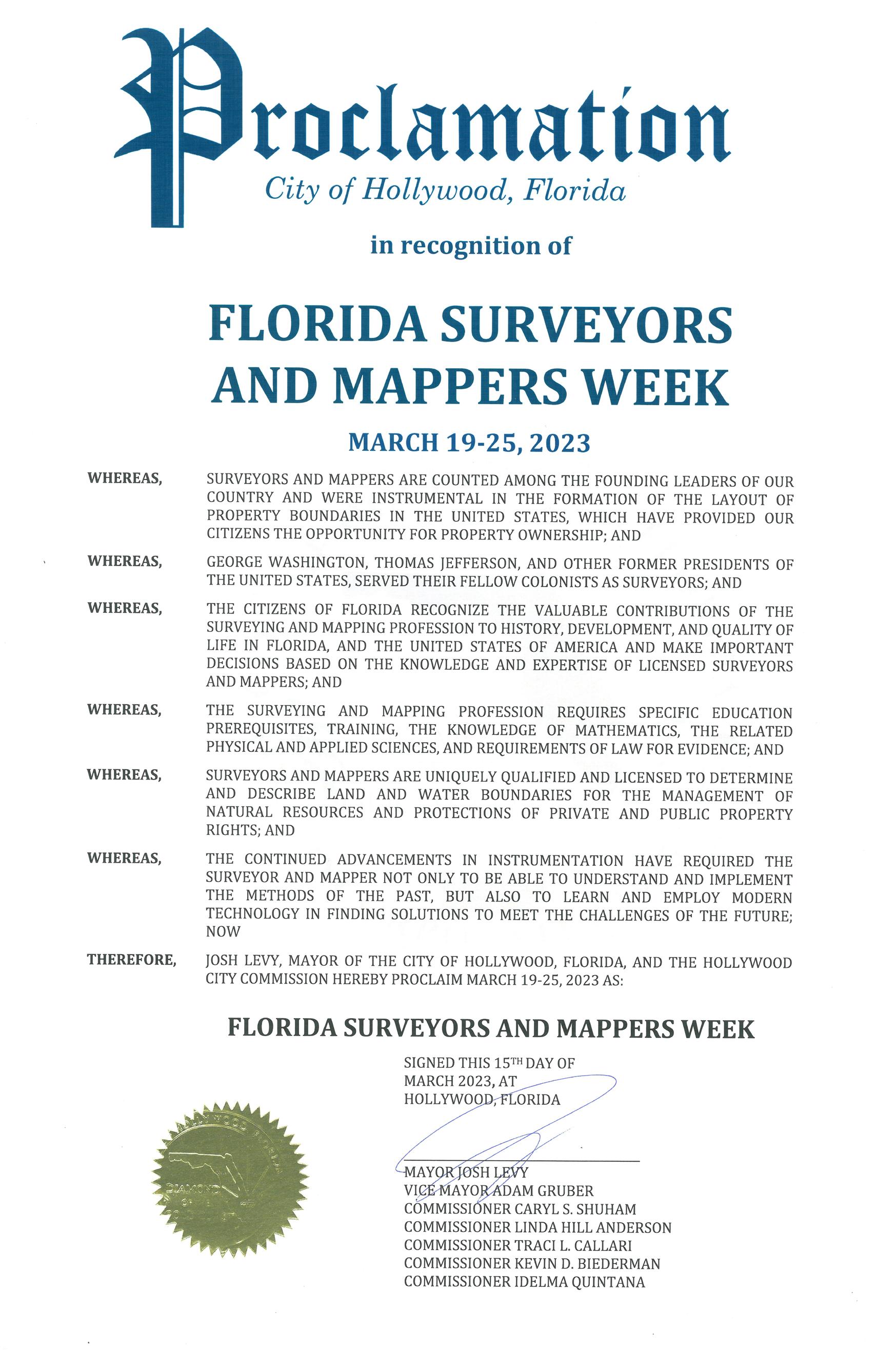
City of Hollywood
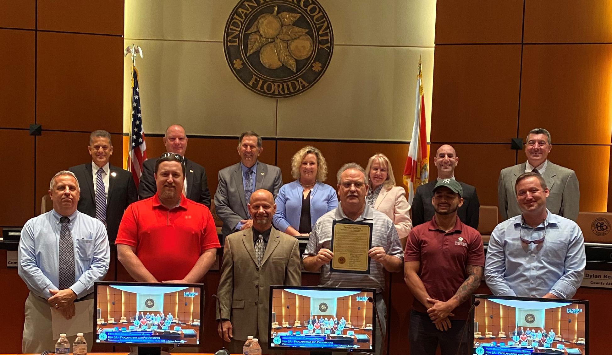
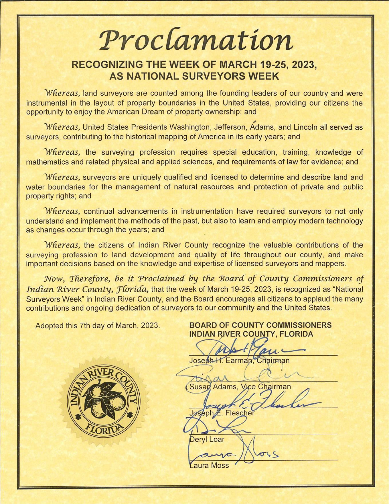
Indian River County
The Florida Surveyor Page 42
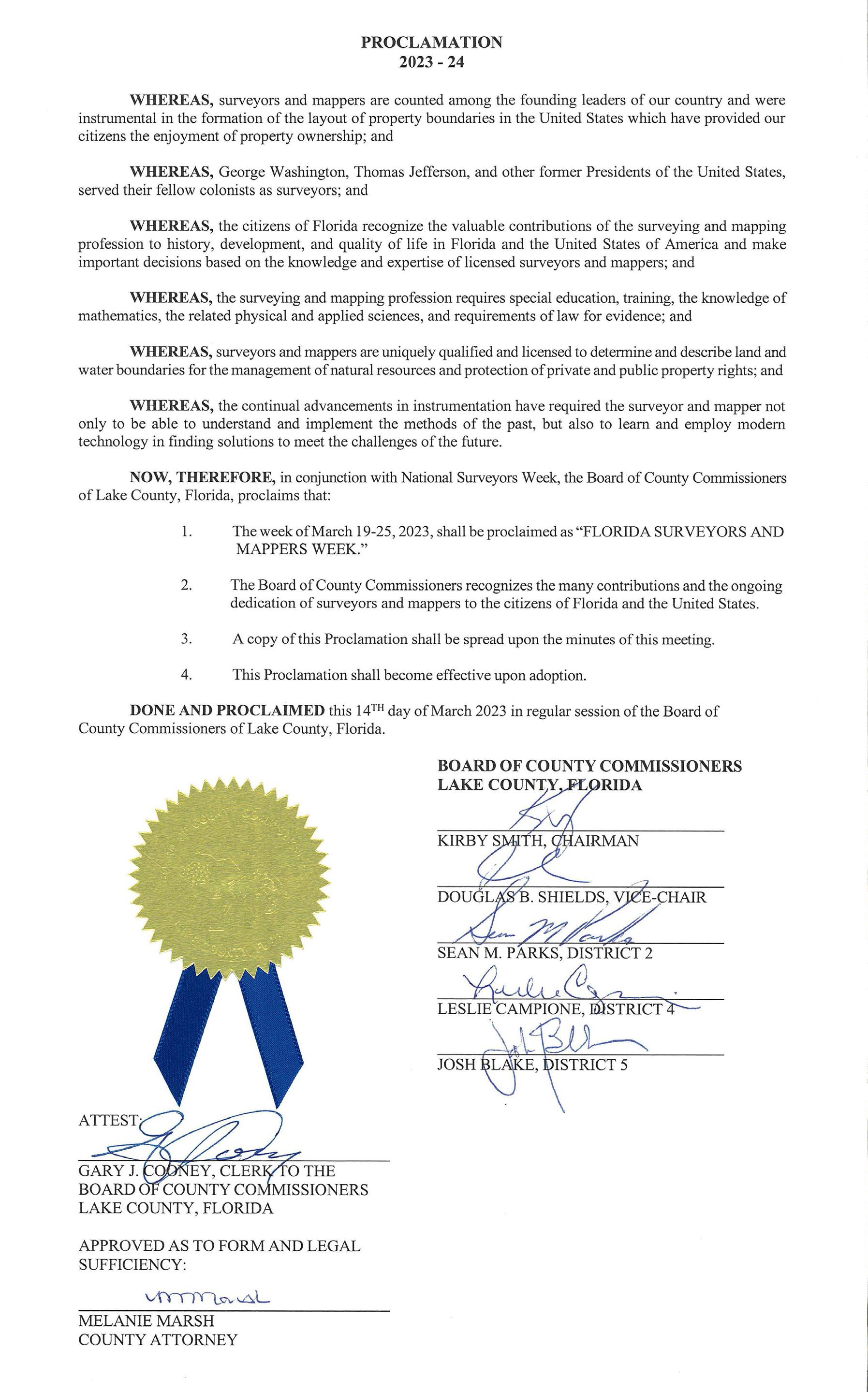
Lake County
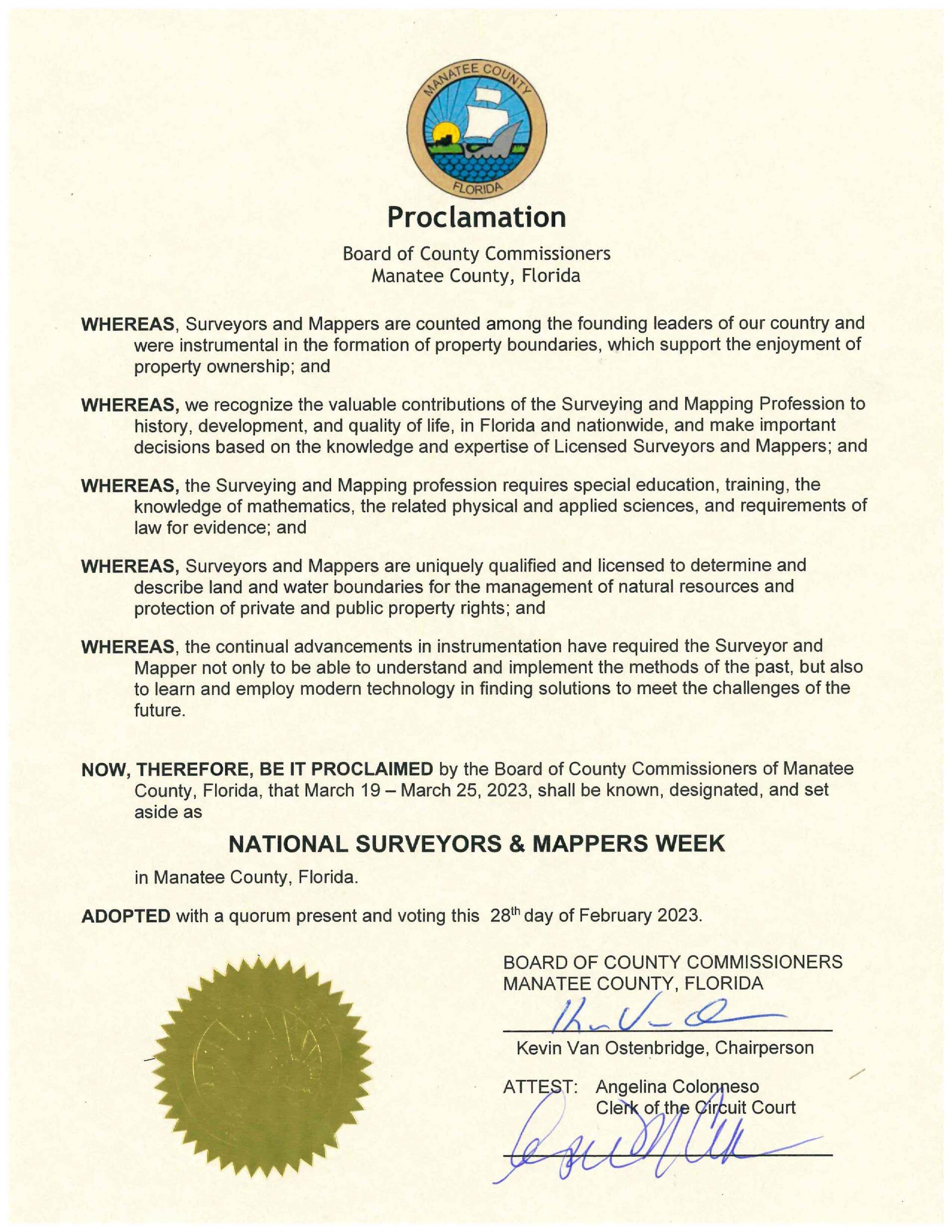
Manatee County
The Florida Surveyor Page 44
Martin County
Orange County

Page 46
City of Orlando
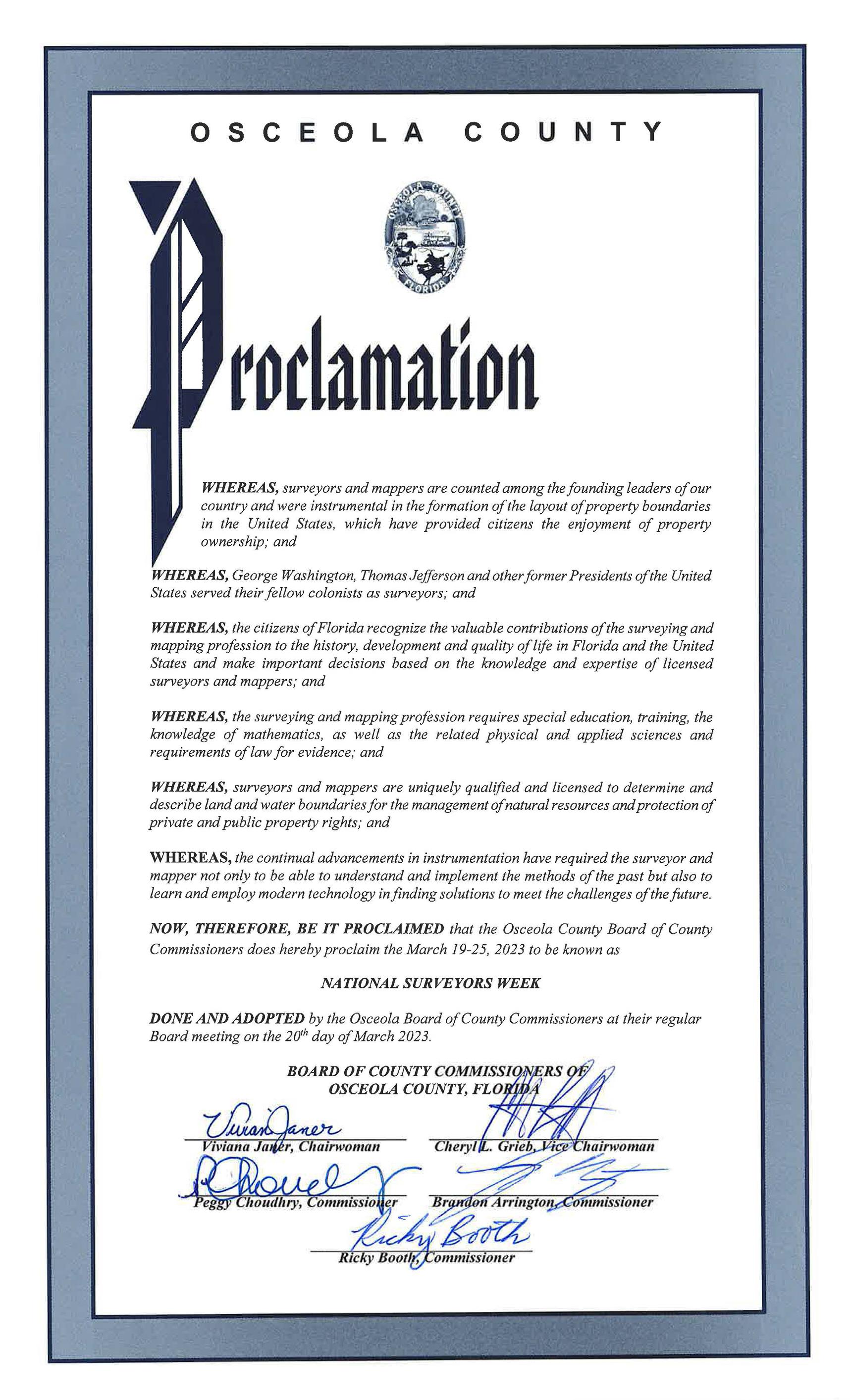
WHEREAS, surveyors and mappers were among the founding leaders of our country and were instrumental in the formation of the layout of property boundaries in the United States; and
WHEREAS, George Washington, Thomas Jefferson and other former Presidents of the United States served their fellow colonists as surveyors; and

WHEREAS, the surveying and mapping profession requires special education, training, knowledge of mathematics and physical and applied sciences and requirements of law for evidence; and
WHEREAS, surveyors and mappers are uniquely qualified and licensed to determine and describe land and water boundaries for the management of natural resources and protection of private and public property rights; and
WHEREAS, the continual advancements in instrumentation have required the surveyor and mapper not only to be able to understand and implement the methods of the past, but also to learn and employ modern technology in finding solutions to meet the challenges of the future; and
WHEREAS, the City of Orlando celebrates the valuable contributions of surveyors and mappers to our community and appreciates their professionalism and commitment, recognizing that important decisions are made based on the knowledge and expertise of licensed surveyors and mappers;
NOW, THEREFORE, I, Buddy Dyer, Mayor of the City of Orlando; do hereby proclaim March 19-25, 2023, as

“National Surveyors and Mappers Week and Florida Surveyors and Mappers Week” in the City of Orlando.
IN WITNESS WHEREOF, I hereunto have set my hand and caused the Seal of the City of Orlando to be affixed this 19th day of March, 2023.

Osceola County
The Florida Surveyor Page 50
of
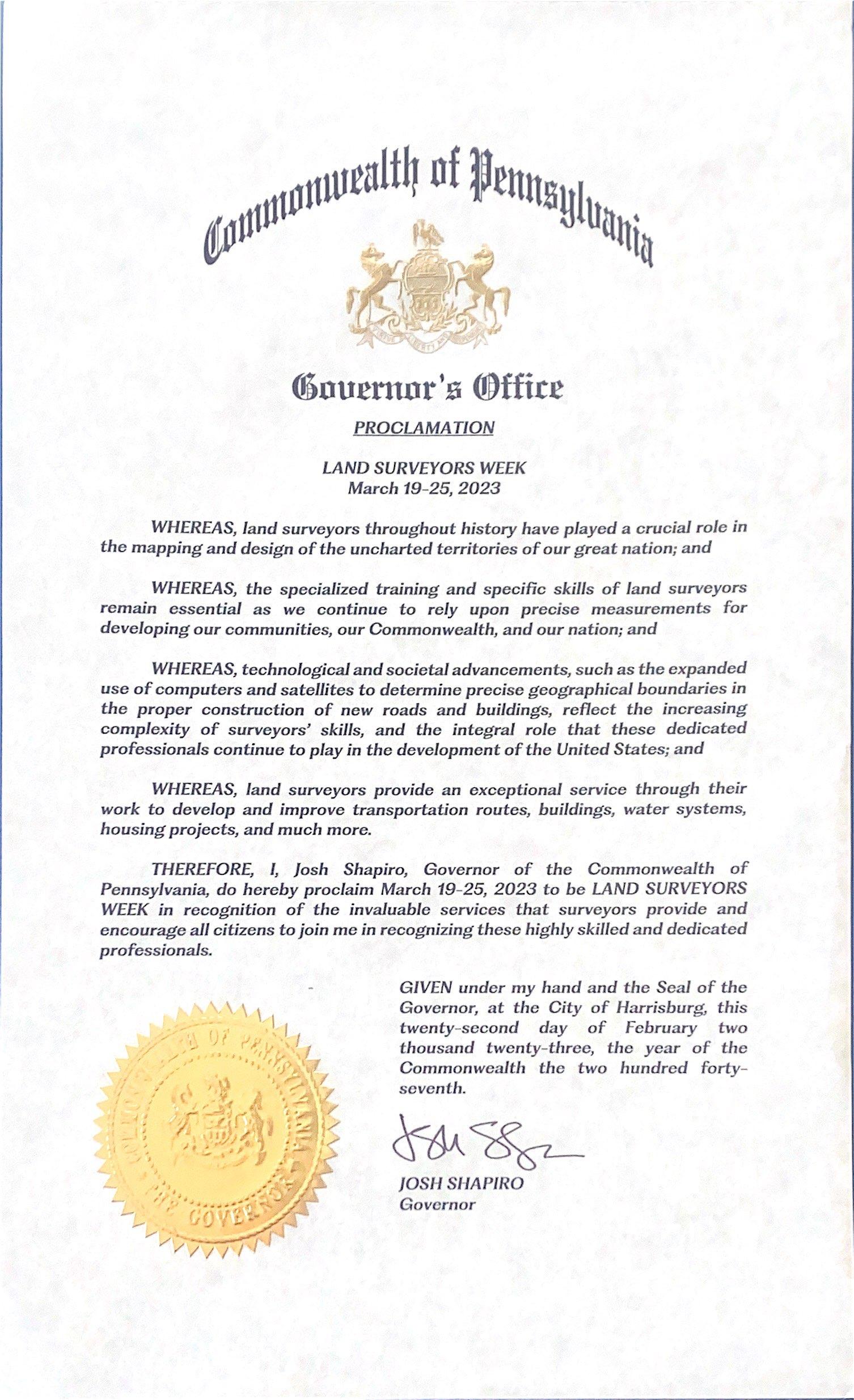
Commonwealth
Pennsylvania
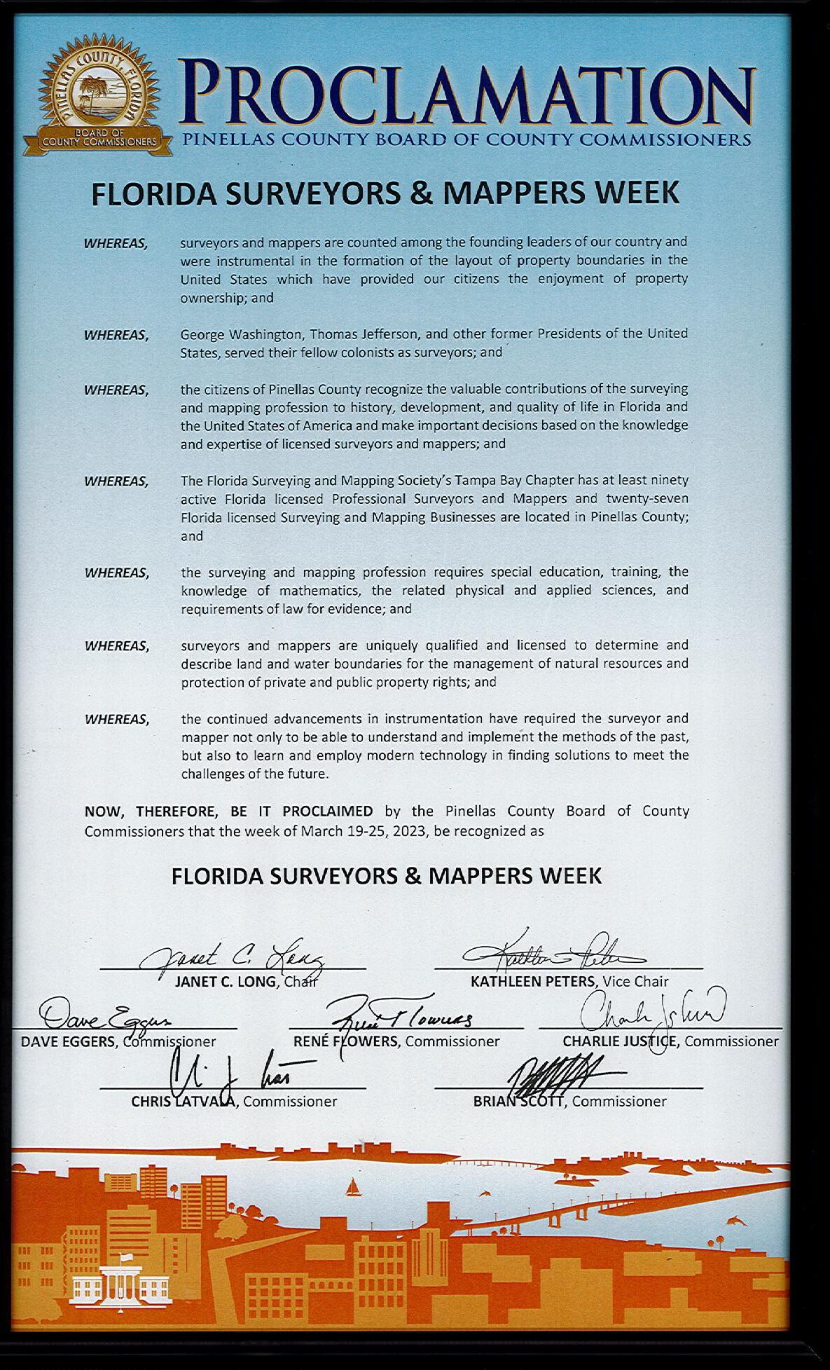
Pinellas County
City of Pompano Beach

The Florida Surveyor Page 52
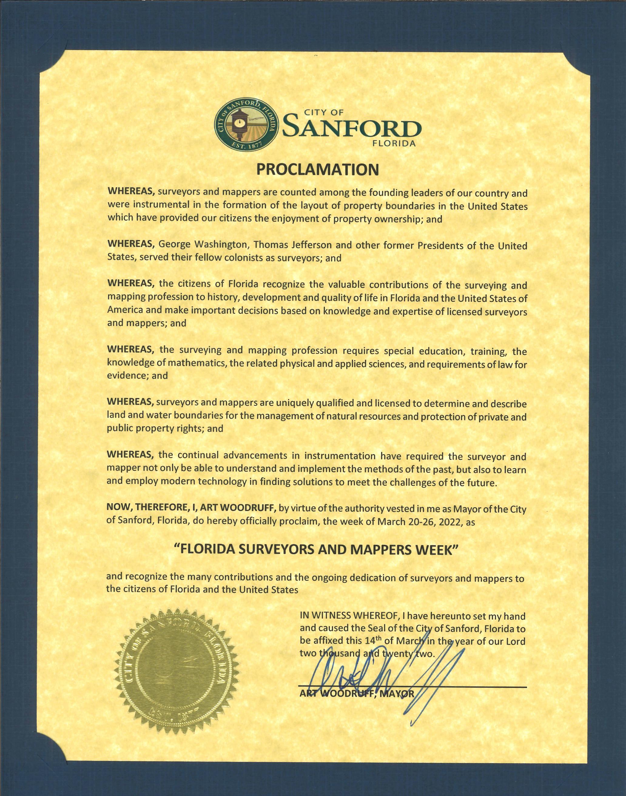
City of Sanford
FSMS will be an Exhibitor at the FIG Conference in May and we’re looking for any interesting surveying photos to showcase at our booth. This is a chance to tell a story to the world of what surveying in Florida has looked like throughout the years. If interested, please send your photos to communications@fsms.org.
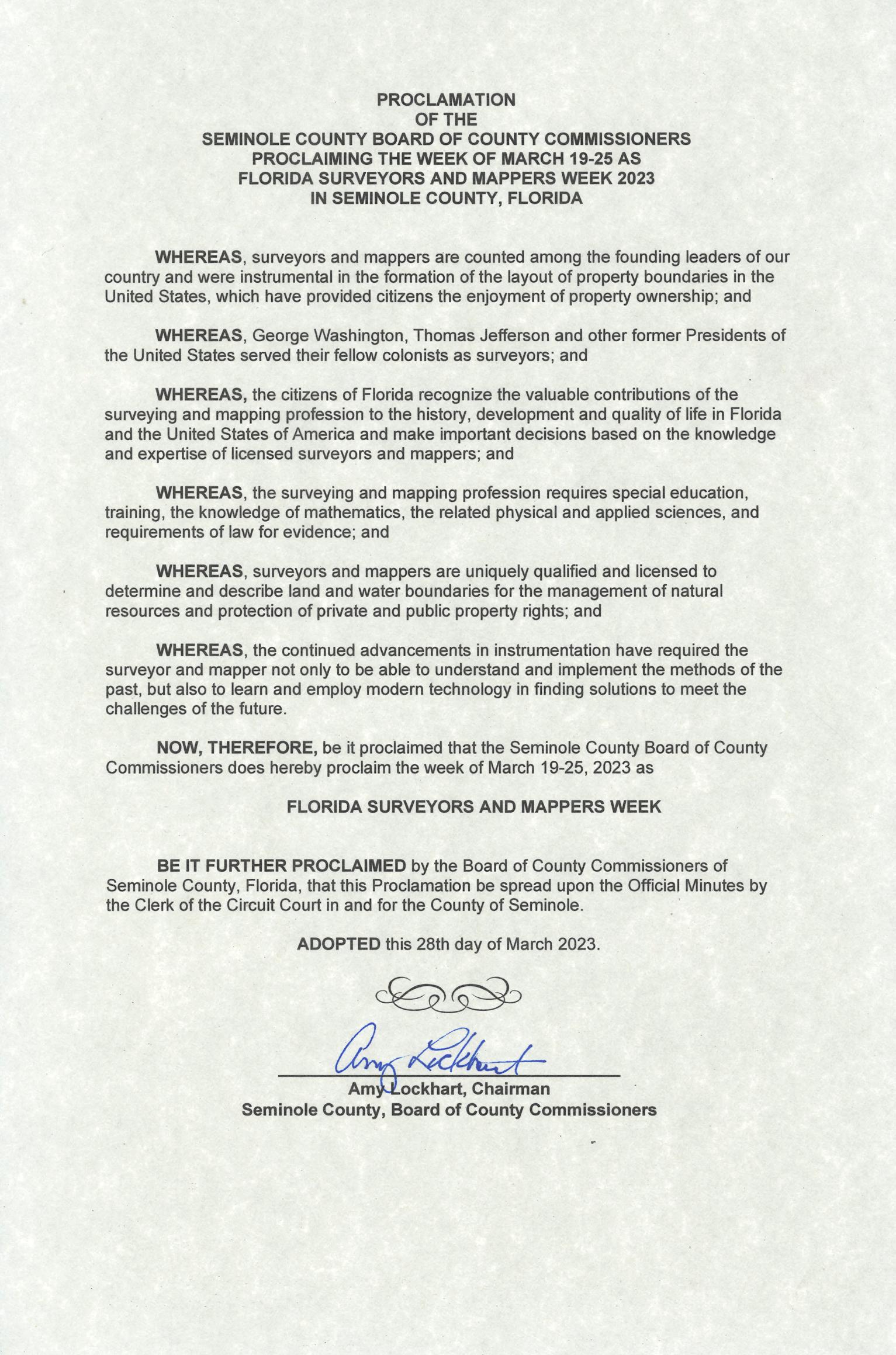
Seminole County
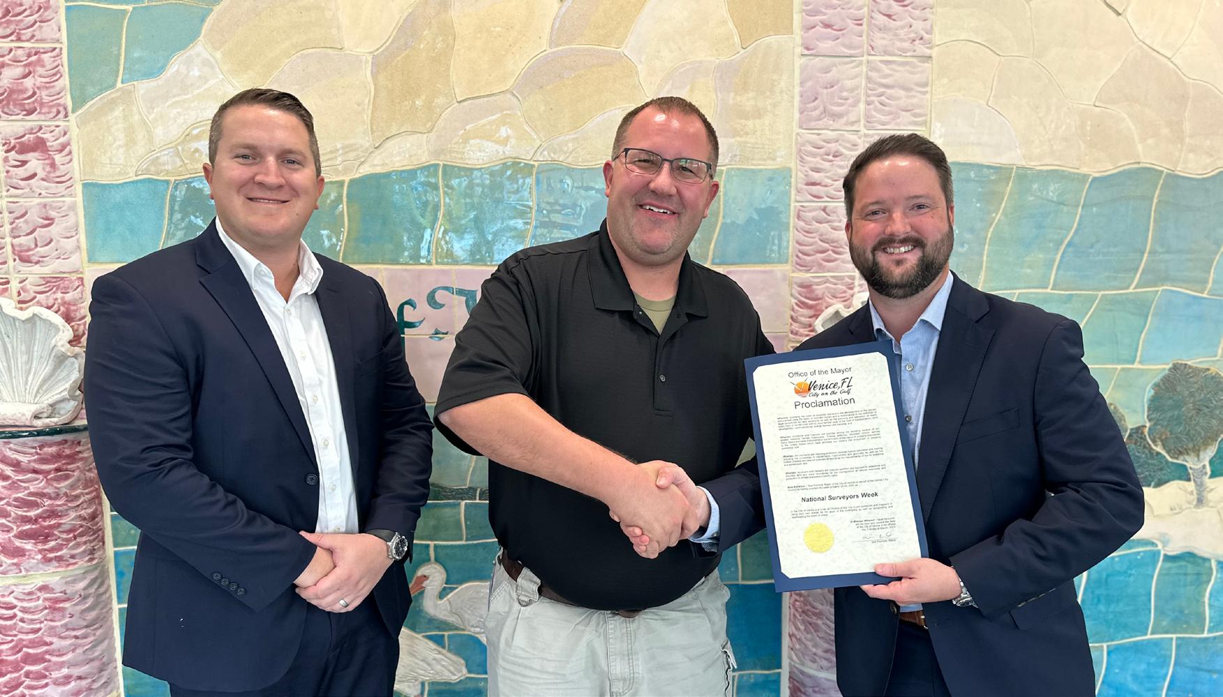
City of Venice
The Florida Surveyor Page 56
Exhibitor Opportunities

68th Annual Conference at Saddlebrook Resort in Wesley Chapel, FL on July 26th – July 29th


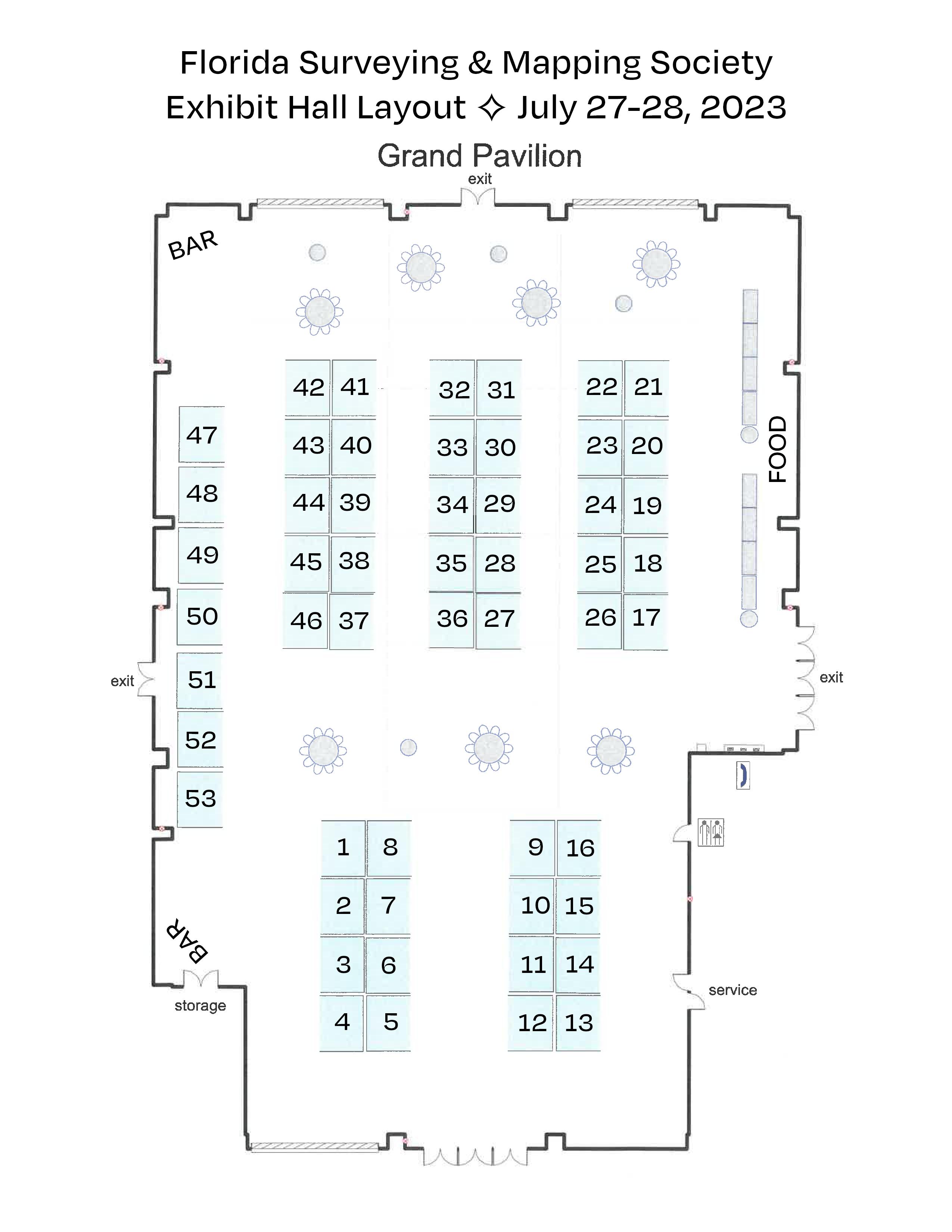

Exhibitor Opportunities
*Only 1 Platinum Exhibitor allowed. All other levels can have multiple exhibitors
PLATINUM EXHIBITOR*
$4,700
• Company Name and Logo on a Banner overhanging the Registration Desk
• Company Bio and Logo in the Confer ence Program Book
• 1 month free full-page ad in The Florida S urveyor
• Sustaining Firms will receive an additional month f ree ad in The Florida Surveyor
• Recognition in Confer ence Edition of The Florida Surveyor
• Recognition on FSMS.org in Header Ad Banner for 2 months
• Logo with Hyperlink to Website displayed on FSMS.org
• Complimentary full page ad in Conference Pr ogram Book
• 2 night complimentary hotel stay
• Two Packet 1 Registrations (Each Registration includes 1 BBQ Ticket, 1 Exhibitor Luncheon
Ticket, 1 Recognition Banquet Ticket, & 6 Saturday Seminar CECs)
• 2 Floor Clings with Logo displayed in Exhibit Hall
• 2 Booths
• Opportunity to Speak at Welcome BBQ
GOLD EXHIBITOR
$3,500
• Company Bio and Logo in the Conference Program Book
• 1 month free half-page ad in The Florida S urveyor
• Sustaining Firms will receive an additional month f ree ad in The Florida Surveyor
• Recognition in Confer ence Edition of The Florida Surveyor
• Logo with Hyperlink to Website displayed on FSMS.org
• 1 night complimentary hotel stay
• One Packet 1 Registration (Each Registration includes 1 BBQ Ticket, 1 Exhibitor Luncheon
Ticket, 1 Recognition Banquet Ticket, & 6 Saturday Seminar CECs)
• 1 Floor Cling with Logo displayed in Exhibit Hall
• Opportunity to Speak at Welcome BBQ
SOLD
SILVER EXHIBITOR
$2,000
• Company Bio and Logo in the Conference Program Book
• 1 month free half-page ad in The Florida Surveyor
• Sustaining Firms will receive an additional month f ree ad in The Florida Surveyor
• Recognition in Confer ence Edition of The Florida Surveyor
• Logo with Hyperlink to Website displayed on FSMS.org
• 2 Welcome BBQ tickets
CONFERENCE EXHIBITOR
$1,500
• Company Bio and Logo in the Conference Program Book
• 1 month free half-page ad in The Florida Surveyor
• Sustaining Firms will receive an additional month f ree ad in The Florida Surveyor
• Recognition in Confer ence Edition of The Florida Surveyor
• Logo with Hyperlink to Website displayed on FSMS.org
ALL EXHIBITORS WILL RECEIVE:
8’ x 10’ draped booth with 10’ backdrop and 36” side rails
7” x 44” Sign provided by Request Only!
6’ draped table, 2 chairs and waste basket
4 name tags for booth personnel per booth
2 lunch tickets per booth for Friday
Attendee List
Additional Booths can be purchased for $850 per Booth
—
—
Exhibitor Opportunities
68th Annual Conference Program Book Advertising
1 full page 5.5” (width) x 8.5” (height)
7.5% sales tax
1/2 page 5.5” (width) x 4.25” (height)
7.5% sales tax
Contact N ame
Ads must be in .pdf, .jpg, or .png format
We agree to the terms & conditions in the rate schedule.
Print Name Signature
MAIL CHECK AND FORM TO: Florida Surveying & Mapping Society P.O. Box 850001-243, Orlando, FL 32885-0243
Email: Education@FSMS.org
Payment Information:
Check Enclosed AE/Discover/M astercard/Visa
Card Number
CCV/Card Identification # Billing Zip Code
Signature
Card Expiration Date
$200.00
$ 15.00 TOTAL $215.00
$125.00
$
TOTAL $134.38
9.38
Sponsor/Advertiser
Address City State Zip Phone Email
68th Annual Conference Showcase Flyer Inserts


Cost - $100
Or, FSMS can print your flyers on letter size copy paper (8.5” x 11”) with B & W print
Cost
Create a Unique Touchpoint with Your Showcase Flyer Insert!
inserts)
An additional way to showcase your company at our Annual Conference is via our Attendee Registration Packets. Prepare your company’s flyer and ship (200
to the Administrative Office for arrival by June 15th.
Company Contact Name Signature Address City State Zip Method of Payment: Check Credit Card(AE/D iscover/MasterCard/Visa) Card # Exp. Date CCV/Card Identification # Billing Zip Code Email MAIL CHECK AND FORM TO: Florida Surveying & Mapping Society P.O. Box 850001-243, Orlando, FL 32885-0243 Email: Education@FSMS.org
- $200 We agree to the terms & conditions in the rate schedule.
ARCHIVES FROM THE

The Florida Surveyor Page 63
Instruments and Methods for Surveying and Mapping
ACSM, National Report to FIG, Commission V.
Thirteenth International Congress of Surveyors
Wiesbaden, Germany, September 1-10, 1971
By DR. ERICH H. RUTSCHEIDT chief, geosciences division, department of geodesy and geophysics, u.s. army topographic command secretary,
commission v and
CHARLES H. ANDREGG
technical director, mapping, charting and geodesy u.s. department of defense
a lternate u. s. m ember, commission v
American Congress on Surveying and Mapping
(Originally published June 1971 in Surveying and Mapping)
THIS REPORT summarizes the applications in the United States of the developments and innovations in instruments and methods since the last meeting of the FIG in September 1968. The past three years have seen refinement in accuracies and operating characteristics of classical instruments, operational application of new equipment and methods made, and additional applied research initiated in the fields of new equipment, methods, and their combinations.
Increased sophistication of electronics application remains the major factor in the design and improvement of instruments and techniques for all
phases of surveying and mapping, particularly in the arts of mensuration, analysis, reduction and adjustment.
GEODETIC SURVEYS
The past three year period has seen most activities dealing with the provision and de velopment of geodetic equipment and meth ods directed at improvements to increase accuracies and time rates of data acquisition and reduction, with a particular emphasis on satellite geodesy and precise baseline and traverse measurements. A number of de velopments have become operational with some results meeting
April 2023 Page 64
Instruments and Methods for Surveying and Mapping
or exceeding original expectations. Satellite geodesy has grown into an accepted geodetic tool throughout the world.
Electronic Optical Distance Measuring Equipment
The increase in the use of Electronic Dis tance Measuring (EDM) equipment in the United States is demonstrated by its wide application in all survey mensuration, from cadastral work to the measurement of geo detically precise baselines. Among its many interesting new uses is the measuring of dis placements in large structures such as dams and measuring the movements of the earth's crust in fault zones.
The most significant developments in EDM equipment in the last three years have been in instruments using laser and infra-red beams as the carrier waves for measurement information. Laser instru ments have been developed for measuring long distances (up to 90 kms night and 50 kms day) as well as short distances (up to 6 kms night and day). Infra-red instruments are available for measuring short distances (up to 3 kms night and day). The trend in the development of both types of equip ment has been toward automation of the measurement system, providing direct digi tal
This report was published from materials furnished by the National Ocean Survey, the U.S. Geological Survey, and the Department of Defense. It has been consolidated and organized by Dr. Erich H. Rutscheidt, Chief Geosciences Division, Department of Geodesy and Geophysics, U.S. Army Topographic Command.
readouts. Some of the short-range equipments use oscillators that require little or no warm-up time, reducing total measure ment time, including instrument set-up time, to five minutes or less.
Improvements in EDM equipment using the microwave principle have also been made. Tellurometer has developed the MRS 4 using 35 GHz as the carrier fre quency.
During the past few years advances in solid state electronics, optical modulation and detection techniques and laser increased the potential for a new generation of dis tancemeasuring instruments operating at optical wavelengths. Characteristics of the geodetic instruments which have been de veloped are ease of operation, increased day and night time range, and an absolute ac curacy of one millimeter plus or minus the error due to refraction and uncertainty in the value for the velocity of light in vacuum. This implies that at distances beyond a few hundred meters the instruments might be expected to give answers comparable to those obtained with Invar tapes. In addi tion, there is some promise of techniques for measuring the refractive index of the air over the entire line of sight, thus increas ing the accuracy of measurements at longer distances.
Over the past eighteen months, evaluation has been in progress on one of the first of this new generation
Page 65
Simplified reconstruction of Ptolemy's nine-ringed astronomical instrument called "Meteoroscope," as described in the hidden manuscript.
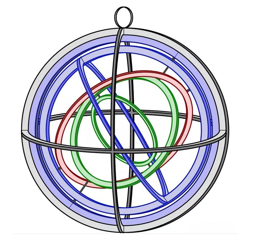
DID YOU KNOW?
Ptolemy's Meteoroscope was a device known to calculate heights and distances, often in relation to celestial bodies. It has been referenced in several ancient texts, including Ptolemy's Geography. However, details of its structure and operation were lacking, until now. Researchers have now unveiled a hidden manuscript on a reused parchment believed to have been written by Greek astronomer, geographer, and mathematician Claudius Ptolemy.
(Newsweek, March 28, 2023)
Source
April 2023 Page 66
Instruments and Methods for Surveying and Mapping
of instruments, the “Geodolite,” built by Spectra-Physics Cor poration of Mountain View, California. The instrument projects the beam from a colli mated He-Ne laser to a corner cube retro -reflector target and measures the distance to the target by comparing the phase of the modulated outgoing beam with that of the returning beam. The shortest modulation wavelength has been made exactly 3.0479947 meters (10 feet), in dry air at 760 mm of Hg and 20° Centigrade, by se lecting a modulation frequency of 49.163707 megahertz. The output of the instrument is a voltage proportional to the distance measured, one volt per 0.3479947 meters (one foot) over the modulation wavelength. Distances may be read to about 0.3 milli meters or one millivolt necessitating a good voltmeter as an accessory piece of equip ment. To resolve ambiguities a total of five wavelengths, each differing from the previ ous one by a factor of ten, are switch select able giving a longest ambiguity interval of over 30 kilometers.
An example of a long distance measured with electro-optical techniques is a 400-mile traverse connection, being executed by the U.S. Army Topographic Command. A positional relationship between terminal points of at least 1 part in 10 6 was required.
The distance-measuring equipment se lected consisted of 1) a Model 4L Geodi meter which was modified
with a stronger laser unit to obtain a transmitted light out put of about 2 milliwatts, 2) a Model 8 Geodimeter which normally has a trans mitted light output of about 2.5 milliwatts, and 3) a Geodolite which was modified to permit the installation of a 25 milliwatt laser which gave a transmitted light output of about 10 milliwatts. The modification of the Model 4L Geodimeter and the Geodilite to increase its power output was con sidered essential if the project was to be successful because there was an immediate requirement to directly measure individual distances of 50, 71 and 83 kilometers. The modifications mentioned above proved to be operationally successful. An unexpected re sult was the capacity of the Model 8 Geo dimeter with its 2.5 milliwatt transmitted power to measure all three of these distances.
In addition to the capacity of these instruments to measure the long lines, there was a requirement for obtaining a comparison of distances as determined by different instruments which would produce ratios of comparisons exceeding 1 part in 106. Of these rather limited number of longdistance determinations, the ratio of comparison exceeded the accuracies required. The excellent comparisons are a result of the quality of the instruments and the attention given to obtaining ambient temperatures throughout the entire length of each line. This is, and continues to be, accomplished by using a thermistor
The Florida Surveyor Page 67

equipped aircraft which flies the line during measurement.
Based on the results obtained to date and continued improvement in the power of the light source, it appears that lines of 100 kilometers in length will soon be measured.
A concept for the development of an ultra-precise geodetic baseline has been proposed. The method is that of optical interferometry using the long coherent length and precise wavelength characteristics of the stabilized single frequency gas laser. As proposed, the baseline might also serve as a calibration range for distance-measuring equipment and for a very accurate determination of the velocity of light. Essentially, the concept describes a method of measuring a short geodetic baseline with an absolute accuracy approaching 1 in 10 8. A preliminary evaluation has been made with an available advanced optical distancemeasuring instrument which uses the phase comparison technique. The instrument was tested for resolution, distortion over a complete modulation wavelength, offset or zero error, precision, and accuracy at distances up to 1.6 kilometers. Results of these tests indicate an error in distance measurements which can be assigned to the instrument of about 1 millimeter.
Small Movement Measurement
Techniques for measuring small
movements in large structures make use of advanced-type measuring instruments, as well as modified measuring techniques. Knowledge of the refractive index of the air is not required. Typically, for measurements of the greatest precision, triangulation has been the preferred method. In recent times, however, it has been recognized that atmospheric vagaries limit the accuracy of triangulation. Distance-measurement meth ods have similar problems. The degree to which the refractive index can be ascer tained along the entire measuring path limits accuracy, so that little or no advantage over triangulation may be expected. Since absolute accuracy in many cases is not re quired, these methods are still used, in the case of a dam or other large engineering structures.
Frequently it is only necessary to measure displacements of the structure relative to some nearby point which is assumed to be stationary. In this case the atmosphere might be expected to influence measure ments made along similar paths in much the same way. Thus, although the measured distances might be in error in an absolute sense, the differences between them can be accurately determined.
This technique was applied along a 2500- meter section of an earth dam near Sardis, Mississippi. To minimize the effects of unsuspected variations in the refractive in dex, all paths along which distances were measured
The Florida Surveyor Page 69
Instruments and Methods for Surveying and Mapping
were above similar topography, and measurements were made rapidly to avoid large changes in refractive index which might be expected to occur in a non linear fashion as a function of time.
Microwave Angle Measurement
Recent experiments with microwave de tectors indicate that horizontal directions may be determined with an absolute ac curacy of 5 arc seconds. The practicability factors for treatment of atmospheric effects and for dimensional configuration seem to favor the higher microwave frequencies, specifically 85–94 GHz, although some work has been done at 9.4, 18.8, and 35 GHz. The most promising feature of these experiments is the capability to make angular measure ment day or night, in clear weather or under conditions of fog, smoke, haze and precipitation at ranges up to 50 kms. The remaining development is expected to bridge the gap between the early experiments and a practical field surveying instrument. However, further investigations are required in order to determine the optimum frequency for a practical field surveying instrument for geodetic purposes. The prospects for a very short-range lightweight and less accurate instrument for military survey purposes are promising.
Encoder Theodolite
The recently accelerated development of shaft-angle encoders and resolvers for auto mated digital systems has
enabled their economical application to surveying instru ments. The choice of types available now include both optical and electronic, and the techniques include both absolute and incremental. The resolution of the most re cent developments has been carried to less than 1 arc second and the readout or dis play can be in the form of an instrument panel meter, magnetic tape, punched paper tape or filmed record. When applied to a directional theodolite, these devices provide digital data that can go directly from field measuring operations to a data processing center. One such theodolite is already being used in quantity in Europe and several others are under development in both Europe and the United States. The U.S. Army Engineer Topographic Laboratories are currently retrofitting a theodolite with both vertical and horizontal encoders for military survey application. The output is designed to be a visual display with a 0.1 mil resolution.
Initial Surveying Equipment
Inertial principles and components are currently being applied by the U.S. Army Topographic Command to surveying. The Position and Azimuth Determining System (PADS), an all-inertial system aided by a laser velocimeter, will be jeep-mounted and capable of providing position, elevation and azimuth to an accuracy suitable for mili tary or reconnaissance surveys. Modified field operational techniques may provide ac curacies suitable for engineer use. The fabrication of an
April 2023 Page 70 N atio Nal R epo Rt to F i G, C ommissio N V
Instruments and Methods for Surveying and Mapping
experimental model is scheduled to begin early in FY 71.
The desirability of gyroscopic azimuth in struments for surveying has been established over the past few years. To date, however, the gyro-instruments designed for surveying generally have either lacked easy portability or required experienced operators to achieve satisfactory results.
The lightweight gyro-azimuth surveying instrument under development is designed to provide an accurate, easy-to-operate, and highly portable instrument that can achieve good performance reliability in the field environment. It utilizes the well-known band suspended, pendulous design to achieve maximum decoupling of the gyroscopic element from undesirable forces due to vibra tion and tripod setting. A gyrotracking servo-1oop is used to avoid twisting of the suspension band. Finally the oscillation about north— typical of band-suspended, penduloustype instruments—is avoided by an electrical damping technique which causes the gyroscope to settle in the merid ian. The use of damping affords a minimum observing time and avoids mathematical computations in obtaining the final azimuth. The instrument can achieve an accuracy of better than 0.3 mil (1 minute of arc) at mid-latitudes in a settling time of 20 min utes. The weight design goal is 40 pounds.
Observing and calibrating techniques used by the Lear-Siegler Co. in the above lightweight gyro-surveyinginstrument to gether, with sacrifices in both observing time and weight may make it possible to achieve an instrument suitable for some geodetic usage.
Combined Function Instruments
For several years the concept of measur ing gravity in an airborne vehicle has been pursued by the geodetic community. Several tests have been made with gravity meters installed in fixed-wing aircraft. An initial test employing a helicopter as a ve hicle was performed in the spring of 1965. Since that period several more tests have been completed b the U.S. Army Topo graphic Command (TOPOCOM) the Air Fore Cambridge Research Laboratories and the USAF 1st Geodetic Survey Squad ron. Because of problems that developed with data reduction, the system has not been certified as operational.
The Helicopter Gravity Measuring
System (HGMS) is an integrated equipment configuration consisting of several components or sub-systems; LaCoste and Romberg stable platform gravity meter, Rosemont pressure port calibrator, 35 mm strip camera, HIRAN navigational system, Spectro-Physics laser altimeter, Lancer digital data logger, and the necessary interface and analog recording monitors. Determination of the x,y,z coordinates, as related to local geodetic control,
The Florida Surveyor Page 71
is measured by these sub-systems; HIRAN for latitude and longitude, pressure port calibrator for establishing a barometric surface for elevation reference, and the laser altimeter for flight path elevation control.
An accurate navigation system is of prime importance since the pointto-point results are used to establish course as well as speed of the aircraft. Excessive errors in either component result in a substantial correction to the recorded gravity values. Several systems have been used in test programs: on-board radar, LORAC, Raydist, SHORAN, HIRAN, on-board Doppler, and Cubic Autotape. Only two systems—HIRAN and Autotape— have been found suitable for both over-land and over-water flight control. The most recent tests were performed with HIRAN resulting in acceptable accuracies of 50 feet CEP, 0°.3 to 0°.5 course accuracy, and 0.3 knots to 0.5 knots speed accuracy. The Cubic Autotape, in tests performed separate from the HGMS operation, gave excellent results (± 2 meters repeatability in TOPOCOM tests).
Determination of an airborne reference for elevation control has been a difficult task. The sensitivity of the Rosemont pressure port calibrator has provided an accurate tool for establishing a reference in the sky. After flight altitude is reached the calibrator sensor traps a sampling of air and records any deviations from this reference sample (plane). The
barometric surface is not an ideal reference since its stability is affected by general and local atmospheric conditions.
The laser altimeter (with an accuracy of 1:10,000) has a two-fold purpose as used in conjunction with the calibrator. By fly ing on the surface plane over ground refer ence elevation sources, viz., rivers, lakes, roads, etc., the altitude of the barometric plane is fixed along the flight path. Since the laser altimeter records continuously, a profile of the terrain is recorded along the flight path. As known ground elevation sources are flown over, an update of the barometric surface allows necessary correc tive factors to be made to the flight profile, and accurate elevations of points along the ground can be determined. During these recordings the 35 mm camera takes a con tinuous photograph of the flight path. Re cordings of all systems are synchronized to fiducial marks on the photography for the purpose of relating the ground features to the graphical altimeter record.
The most sophisticated airborne cartographic and geodetic data acquisition sys tem in existence is designated the AN/ USQ–28 system and is operated by the U.S. Air Force's Aerospace Cartographic and Geodetic Service (ACGS) of the Mili tary Airlift Command (MAC). It is housed aboard a four-engine jet aircraft and con sists of three electronically interfaced sys tems: the photomapping system, the Ter rain
April 2023 Page 72
N atio Nal R epo Rt to F i G, C ommissio N V
Instruments and Methods for Surveying and Mapping
Profile Recorder (TPR) System, and the distance-measuring system (SHIRAN).
The photomapping system features two KC-6A cameras in vertically-stabilized mounts controlled by HYPERNAS II In ertial Reference Unit (IRU). The KC6A is the most advanced U.S. mapping camera (6-inch focal length, 9 x 9-inch format). Some of its outstanding features are the Geocon IV colorcorrected lens with 93-degree diagonal field and 38 lines/mm reso lution (AWAR), RAPIDYNE shutter, automatic exposure control, image motion compensation, and a 25-point platen reseau grid. In addition, the camera provides a fine verticality registration block and a digital data registration block which appear in the margin of each exposed frame. Besides providing vertical control for the mapping cameras, the IRU is an integral part of an inertial navigation system used for precise flight-line navigation.
The TPR is a precise, narrow-beam recording radar altimeter which provides a capability of establishing terrain elevations along the ground track of the aircraft. Its relative accuracy between nearby points along the same flight line is ± 10 feet at one sigma level. SHIRAN is a precise long-range, electronic, distancemeasuring equipment (DME) capable of simultaneous measure ment to four ground transponders over ranges in excess of 200 NM. One applica tion of the SHIRAN DME is the extension of geodetic control by trilateration,
in which case the system is capable of measur ing the geodetic distance between two ground stations up to 400 NM apart with a demonstrated onesigma accuracy of ± 0.0023 NM or ± 14 feet (single mission) independent of line length. Another appli cation of the SHIRAN DME is the Hori zontallyControlled Photograph (HCP), in which case the system is used to determine the geodetic position of nadir points of aerial mapping photographs with accuracy of the order of ± 15 feet standard error of position when three or four ground stations are used for control.
The voluminous digital data acquired during an USQ-28 mission are recorded on magnetic tape for processing by a ground computer facility (SDS 920/910 compu ters). The USQ-28 system is complemented by the WS-.430C photo processing and data processing complex housed in self-contained, airliftable trailers which can be deployed to the project operating location.
Automated Horizontal and Vertical Control Acquisitions
The establishment of horizontal and verti cal control for gravity stations in inade quately mapped areas is expensive and time consuming. The U.S. Army Topographic Command, the U.S. Geological Survey and the 1st Geodetic Survey Squadron have acquired Ground Elevation Meter (GEM) Surveying Systems which are being used to establish elevations in support of gravity sur veys and lower
The Florida Surveyor Page 73
order vertical control sur veys. The GEM was built by the Sperry- Sun Well Surveying Company in Houston, Texas, and is mounted in a 1970 GMC Suburban Carryall.
The GEM establishes relative elevations which are obtained through an apparatus which measures the instantaneous angle of inclination of the surface being traversed and the instantaneous velocity of the meter along that path. The assembly consists of a four-wheel drive, fourwheel steer vehicle. A small fifth wheel that provides the veloc ity or distance signal through a pulse gen erator system is mounted on a cantilever arm suspension midway between the front and rear wheels on the left side of the ve hicle. It is lowered to and raised from its operation position by use of a constant pres sure air cylinder. A telescope bar, sus pended between the front and rear axles provides the reference datum for the measurement. A sensitive pendulum mounted on this bar provides the angle measurement for each increment of distance traversed. In addition, the vehicle carries automatic high-speed electronic computing storage and printout computer capability with necessary power supplies for all equipment. The vehicle is fully airconditioned for dust free operation of the electronic computer.
Gravity observations are made from in side the vehicle, using a tripod which is lowered to the ground. The accuracy
of the elevations established varies with the road surface, speed of the vehicle and driv ing technique. The average accuracy ob tained to date is ± 2.0 feet and little diffi culty has been experienced obtaining the 5.0-foot tolerance. Speed and the ability to work in inclement weather are important production factors. The GEM's production rate is approximately three times that of conventional lower order spirit leveling.
Portable Towers
A portable truck-mounted tower developed by the U.S. Geological Survey (USGS) has been used successfully to speed up field surveys for establishing control for topo graphic mapping. Several design changes were made to improve characteristics related to the stability, erection, and mobility of the tower. The 6-inch tube used for an instrument stand was modified from a 6.5-foot length to extend the full length of the tower and be anchored to the ballast tank at the base. This modification provided the stability vitally needed for second-order control surveys. The inner and outer towers assemble in only two sections, each for a working height of 60 feet. The four sections can be telescoped and nested within one another at a length of 32 feet for transport. In the raising or lowering operation, new heavyduty hydraulic lifters swing the tower, fully extended, through a 90° arc at a smooth uniform rate of motion.
April 2023 Page 74
N atio Nal R epo Rt to F i G, C ommissio N V
Why Join FSMS?
LegisLative support –The Legislative Committee and our Lobbyist are committed to keeping the Public and the Surveying and Mapping Profession protected

educationaL Benefits –With recently updated courses, getting your CECs has never been better
networking –Attend our Annual Conference to meet other professionals and meet vendors with all the latest equipment
sociaL Benefits –Attend local chapter meetings to meet individuals with common professional goals
The Florida Surveyor Page 75 Aug/Sept 2021 30
CLICK HERE TO JOIN! Florida Surveying & Mapping Society 1689 Mahan Center Blvd.
A Tallahassee, FL
www.fsms.org
942-1900
Suite
32308
(850)
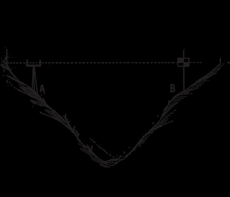
Portable Masts
Variable-length portable masts are being used by the USGS for survey operations where traverse lines must start or end on control stations obscured by hills or high trees. These masts, developed in two models, are extended by a hand-operated winch to heights of 56 and 74 feet above ground level. In operation, the mast lifts a rotating beacon signal light and a Geodimeter reflector above obstructions for survey operations. Guy ropes are provided to secure the extended mast and center the light over the station mark. The mast assembly weighs 115 pounds and telescopes to a length of only 21 feet, so that it may be easily transported.
Electric Signal Lights
The capability of measuring precise distances in daylight contributed to increased use of electric lights as daytime targets for the measurement of angles in geodetic transverses and triangulation. The type of signal light developed by the USGS can accommodate a wide variety of sealedbeam lamps, up to a power rating of 500 watts, including a quartz-halogen lamp that delivers 300,000-beam candlepower at a drain of 55 watts. Several lamps can be stacked vertically over the station mark and pointed in different directions. They can be turned off/on at the station by means of a push-button switch or a 24-hour, 8-day clock timer, or from a remote station by means of an audio-tone generator and
standard field ratio.
Satellite Geodesy
The satellite triangulation programs of the NOS, TOPOCOM and the U.S. Air Force are based on simultaneous observa tions of satellites from widely separated camera stations. The NOS/ TOPOCOM program used a specially designed Wild BC–4 satellite camera (450 mm focal length) and a camera control and monitoring console containing the system's electronic and timing equipment. Only passive satellites were observed in this program. The U.S. Air Force's program used the PC–1000 Stellar Camera (1000 mm focal length) and its associated Model III Elec tronics System which also permits the co ordinated recording of flashing strobe lights mounted on satellites.
The simultaneous observations of a satel lite against the star background, recorded photographically on glass plates for precise mensuration, from camera stations on the earth's surface provide simultaneous spatial directions to the satellite. A direction from each of two camera stations define a plane through the satellite and the two camera stations. This plane, in turn, defines a chord, to include its direction, between the two camera stations. Simultaneous observa tions from two known and one unknown station will permit a solution for the rela tive position of the unknown station.
The NOS/TOPOCOM satellite field
April 2023 Page 76
N atio Nal R epo Rt to F i G, C ommissio N V
Instruments and Methods for Surveying and Mapping
observation program was initiated in June 1966 and completed in November 1970. High-precision baselines for scaling the worldwide network have been measured by electronic traverse in Africa, Australia, Europe and the United States. All satel lite data are now being reduced by the NOS and will be completed in 1972. Results will be the basis for an accurate determina tion of the size and shape of the earth, and for the establishment of a global geodetic datum that approaches an accuracy of 1 part in 10 6. The BC–4 camera system has proven its capabilities and is now being employed by NOS on the North American Densification Project.
The U.S. Air Force's PC–1000 Program was used, in co-observation with HC–4 camera observations, to densify existing networks in South America, and to connect iso lated locations with primary geodetic con trol areas. Internal consistency of this tech nique is better than 1 part in 350,000 at 60.8 percent.
The TOPOCOM SECOR (Sequential Collation of Range) program has been completed. This system measured ranges from four stations, three known and one un known to a transponder in orbit. This geodetic satellite program was designed pri marily for establishing intercontinental geo detic connections determining the relative geographic positions of oceanic islands, and determining the coordinates of other points on the earth's surface for the purpose of creating a uniform world
geodetic network. In addition, it will be used to reduce the uncertainty in the constants now being used for the size and shape of the earth.
The Doppler principle of apparent change in frequency of a radio signal emitted from an artificial satellite is being used to provide accurate positional informa tion in any part of the world. The U.S. Navy Navigation System was designed as an all-weather tool for marine use, but refinements in techniques and instruments have allowed geodesists to locate themselves on an earth-centered surface more accurately than was previously possible. The Satellite Tracking Network (TRANET) operated by the NAVAIR Systems Command pro vides precise ephemerides of the navigation satellite orbits which may be used by geo detic surveyors to obtain positions from Doppler observations from the satellites.
The standard AN/SRN–9(XN–5) receiver has been used by the U.S. Naval Oceanographic Office for Doppler observa tions to provide geodetic positions in varied environments. Raydist transmitter locations were determined on the off-lying islands of South Korea for hydrographic survey con trol. This equipment was also used to lo cate the Loran C antenna at Angissoq, Greenland and the Omega transmitter at La Moure, North Dakota. In each of these surveys the resulting positions were com puted on the Mercury Datum,
The Florida Surveyor Page 77
Fischer Spheroid. Evaluation of cost data as would be expected indicates that surveys by satellite receiver are faster and cheaper than long-line traverses or extensive triangulation or trilateration. New receivers having re fined observing characteristics and greater portability will be used to implement a com plete satellite geodesy program. Experi ments in translocation (simultaneous obser vations of the same satellite by receivers lo cated up to two-hundred miles apart) will be continued and resulting data will be used to augment further the available technology.
The TOPOCOM's Doppler Satellite Program employs man-portable equipment to acquire data for both single-point, earth centered positions and for relative positioning. This system tracks the U.S. Navy Navigation Satellites for which precise ephemerides are available from the Naval Weapons Laboratory (NWL). Using the known orbital data and analyzing the re ceived Doppler frequency shift of the radio signal emitted by the satellites, highly accu rate ground positions can be determined.
The International Telephone and Telegraph (ITT) 5001 Doppler Receiver tests were conducted by TOPOCOM from April to June 1970. During this test an ITT receiver was located at each of the follow ing stations: Herndon, Virginia; Ft. Stewart, Georgia; and Ahoskie, North Carolina. A Backpack
Doppler Receiver also was lo cated at Herndon, Virginia and partici pated in translocations to Ft. Stewart and Ahoskie. The receiver phase locks to the two radio frequency carriers and obtains accumulative Doppler counts at 2-minute intervals displaying partially accumulated counts every 4.6 seconds. The receiver also detects the satellite ephemeris data that are present as modulation on the carriers and processes these data before it is printed. The 5 mHz oscillator is used as a reference against which the satellite signals are com pared to obtain the Doppler count. A miniaturized Doppler Receiver, called Geo ceiver, is now in production and is being made available at this time. The Back pack Doppler Receiver differs from the ITT 5001 Doppler Receiver in that it provides Doppler counts every 2 minutes; is man -transportable; the Doppler counts are stored in memory and read out at the completion of the track; and the satellite ephemeris data are not printed out.
Two methods of determining positions are being tested: the Geodetic Point Positioning and the Translocation Methods. In Geodetic Point Positioning the geocentric coordinates of each station are obtained from multipass Doppler solutions using the NWL long arc ephemeris. The concept of the Translocation Method refers to the determination of the relative distance between two receivers obtained from simultaneous observations of more than one pass of a satellite. In theory
April 2023 Page 78
N atio Nal R epo Rt to F i G, C ommissio N V
systematic errors in the ephemeris should bias the position of each station an equal amount, resulting in a cancellation of the biases when the relative station positions are computed.
Solutions were programmed for and executed on the UNIVAC 1108 Computer. Selective and additive data were processed successively to determine the convergence of the solutions. Convergence of the solutions under the conducted tests appear to be reached with 60 satellite passes and an internal consistency with 2.5 meters with a 90 percent confidence. The accuracies obtained were within 10 meters for the Geodetic Point Positioning Method and 5 meters for the Translocation Method when compared to the NOS precise traverse.
After more than a decade of satellite observations with corresponding developments in data reduction theory and techniques, our present determination include very elaborate gravitational models containing hundreds of terms, and precise worldwide positions good to ± 15 meters. Improved tracking systems and advances in techniques and equipment suggest that future achievements will include submeter accuracies in position determinations.
Stellar Orientation
Research in stellar geodesy represents one step in the development of the theory for the solution to the problem
of determining the center of earth's mass, ground station positioning, the world geocentric geodetic system and the mathematical figure of the earth. ETL by introducing a geogravity coordinate system and a new concept in defining astronomic station positioning has developed a series of formulations for determining the orientation of lines with respect to the mean equator and mean equinox for a given epoch. The station-tosatellite directions resulting from the photograph measurements are used for making the orientation of lines between unknown stations. From among lines so oriented, the astronomic azimuth and zenith distance between nonintervisible stations can be computed, and the intercontinental astronomic azimuth ties can be achieved. This theory described a method for determining the orientation of lines between unknown stations, with respect to a mean equator and equinox at some assumed epoch, in a world geodetic network.
Computer Processing
Improvements made in electronic computer facilities enhanced applications of computer processing in geodetic surveys. The trend in geodetic computations in the USGS is to write master programs to pro vide for the complete computations of a survey network, including preliminary computations on field observations, initial dis tribution of errors and finally a least-square adjustment with printout of results. Other new computer
The Florida Surveyor Page 79
Instruments and Methods for Surveying and Mapping
programs provide for plot ting control diagrams with an automatic plotter, computing geodetic azimuth from observations of circumpolar stars, and for printing star-finding data for astronomic observations.
PHOTOGRAMMETRY
The advances in photogrammetric instru ments and methods is tied to improvements in electro-optical sensing devices and upon electronic computer technology.
Image Correlating and Measuring System
An image correlating and measuring sys tem was developed by the USGS in coopera tion with BAI Corp. to aid in data acquisi tion for analvtical aerotriangulation. The system consists of the correlator, a card punch, and a precision comparator with associated read out and recording equipment. The correlator scans an annular area of the photo graphic image and develops a video signal, or signature, which uniquely defines the scanned scene. The signature is then digitized and stored on a punched card for subsequent correlation with the same scene from another photograph. The operator establishes the correlation to micrometer accuracy by means of dial readings. The comparator measures and records precise x and y machine coordinates of the selected image points. The system can also be used to derive data for registering time-variant imagery of the same scene or imagery from different sensors.
Orthophoto Instrumentation
A new instrumentation system for pro ducing orthophotographs has been designed and fabricated by the USGS. The system includes two com panion instruments, the Orthophotomat and the Autoline. The Orthophotomat is a single-projector instrument for automatic production of orthophotographs from pro files. The Autoline (automatic line follower) uses analog profiles, derived either manually or automatically, as a means of controlling the scanning motions of the Orthophotomat. Three methods with in strumentation are being developed for pro ducing profiles:
(1) An analog profiler has been built for manual scanning and record ing profiles in a stereo-model formed by a doubleprojection plotter; (2) an automatic photographic technique for recording ter rain profiles from a stereoscopic model is under development; (3) prototype instru mentation for scanning existing contour plates to generate profiles is being built.
Stereoimage Alternator System
Image Alternator (SIA) system of view ing stereomodels by means of synchronized rotating shutters has gained wide acceptance in the United States. Most USGS double -projection plotters have been equipped with SIA's. Several commercial firms in the United States have been licensed to manufacture and sell SIA units, and patents have been issued in seven foreign countries. Com patibility of the
April 2023 Page 80
N atio Nal R epo Rt to F i G, C ommissio N V
Florida Surveying and Mapping Continuing Education Provider Offering 25 Years of Dedication, Quality & Trusted Services
Step
1: Choose Course(s)
3 Hour Courses Available
□ A History of the Prime Meridian Marker,
□ Basics of Real Property
□ Digital Signatures for Surveyors
□ Easements and Rights of Ways,
□ Elevation Certificates and the Community Rating System
□ Introduction to Photogrammetry
□ Quality Assurance/Quality Control for the Design Professional and Technical Staff, #9293, 3 CEC
□ Writing Boundary Descriptions
6 Hour Courses
□ Boundaries in Florida
□ Chapter 177, Platting (Plat Law)
□ Critical Communication for Surveying & Mapping Professionals
□ Ethics for the Design Professional
□ Florida Laws
□ Florida Surveying Law and Rule Changes
□ Geographic Information Systems (GIS)
□ History of Surveying,
□ Identification of Native and Non-Native Trees in Florida
□ Land Tenure and Cadastral Systems
□ Map Projections and Plane Coordinate Systems , #7669, 6 CEC
□ Practical Geometry for Surveyors , #7109, 6 CEC
□ Public Land Survey System, #6979, 6 CEC
□ Remote Sensing Applications to Surveying & Mapping, #6972, 6 CEC
The Florida Surveyor Page 81
Billing Address of Credit Card:
IF PAYING BY CHECK, MAIL FORM TO: FSMS, P.O. Box 850001-243, Orlando, Florida 32885-0243
IF PAYING BY CREDIT CARD, FAX OR EMAIL FORM TO: 850.877.4852 education@fsms.org QUESTIONS? CALL 800.237.4384
April 2023 Page 82
FSMS Member EMAILED Fee Quantity Amount 6 CEC $115 Per Course x = $ 3 CEC $58 Per Course x = $ MAILED 6 CEC $125 Per Course x = $ 3 CEC $68 Per Course x = $ TOTAL $ Non Non Name: _ YES _ NO Firm: ____ _ YES _ _ NO Address: ______________________________________________________________________________________ City/State: Email Address: Work Phone: Payment Information: ___
to FSMS) _ VISA/MasterCard/American Express Card
Exp. Date: __ CVV Code:___________
Step 2: Choose Member Type
Check Enclosed (Payable
#: _______
______________________________________ Signature: _____________________________________ __
Provider No. CE11 fsms.org
system with color photograph for lowcost, projection-type stereo -plotters played a considerable part in its gaining acceptance, because heretofore color photographs could be used only in the more complex instruments with a separate optical train for each eye. The latest SIA hardware development was a shutter de signed to operate inside the lamphouse of an ER–55 (Balplex) projector. Another development was headband-type shutters for operators who prefer more flexibility in head position during viewing.
Aerotriangulation Methods
Most aerotriangulation for topographic mapping in the USGS is clone by semianalytical methods. The coordinates (based on an arbitrary origin) of selected photo-images are ob tained from stereo-models in digital form ready for computer input. In the computer, the data are adjusted to control points which have known ground positions and haw been identified on the photographs. Several methods of adjustment are programmed, and the particular program used depends upon the type of terrain, the photo grammetic control requirements, and the instrumentation available. In addition to semi-analytical techniques in use, the IBM/ 360 version of the Geological Survey's di rect geodetic constraint method of fully analytical aerotriangulation reached opera tional status. The maximum size of problem that the program will now handle is 45 photographs. The number
of auxiliary storage units (magnetic tape or disk) required by the program i s only two. Points targeted on the ground for positive identification serve as both hori zontal and vertical control points. The Wild PUG point-transfer device is used to make pass points which are then measured on a OMI Nistri monocomparator. The analytically derived positions and elevations of pass points for model control meet all standard accuracy requirements for topographic map compilation.
Aerotriangulation
The Multiple Station Analytical Triangu lation (MUSAT) program, a simultaneous adjustment technique for analytical aerotriangulation, has been developed by the U.S. Army Engineer Topographic Laboratories. A series of MUSAT programs have evolved over the past six years. The first of the MUSAT series (MUSAT I) is based on investigations and successful development of the simultaneous analytical triangulation technique begun by the Army in 1954. This work has progressed through the development of MUSAT IV, with major technique innovations implemented with each succeeding version. The MUSAT IV program is a particularly efficient general analytical triangulation program for frame photography developed and programmed in FORTRAN V for the UNIVAC 1108 Computer. This program, as in all previous versions, is designed with a production environment in mind, with particular attention given
The Florida Surveyor Page 83
Mapping
Instruments and Methods for Surveying and
2023 eLearning Courses
6 General CEC - $99/course (members)
$120/course (non-members)
• History of Surveying
- Course #7140
• Identification of Native & Non-Native Trees in Florida
- Course #8132
• Ethics for the Design Professional
- Course #8621
• Land Tenure & Cadastral Systems
- Course #8260
• Map Projections & Plane Coordinate Systems - Course #8261
• Public Land Survey System
- Course #7147
• Remote Sensing Applications to Surveying & Mapping
- Course #7148
• Practical Geometry for Surveyors
- Course #7141
3 General CEC - $49/course (members)
$70/course (non-members)
• Elevation Certificates & the Community Rating System
- Course #8256
• Introduction to Photogrammetry
- Course #7968
April 2023 Page 84
Florida Surveying & Mapping Society 1689 Mahan Center Blvd. Suite A Tallahassee, FL 32308 www.fsms.org (850) 942-1900
Instruments and Methods for Surveying and Mapping
to the ease of data input and to the flexibility for accommodating the needs of a wide range of users. The program features a free formatting technique for ease of data input and offers a wide variety of input/ output options to cover the needs of both research and productionoriented users. Preprocessing of image coordinates, including corrections for film deformation, radial and tangential lens distortion, and atmospheric refraction, is provided in several forms. Blunder and data editing features are incorporated, and diagnostic and error messages are given during each phase of the triangulation process. A rigorous least-squares adjustment with an error propagation facility is provided to handle block of virtually unlimited size. (The most recent large block solution involved the solution of 1000 photographs with the MUSAT III program. The triangulation and adjustment of this block was accomplished on the UNIVAC 1108 Computer in 57 minutes.) The mathematical model, based primarily on the collinearity condition, can be constrained by a range measurement between any two points in object space, by groups of points having equal elevation as well as by the more conventional ground and exposure station elements. Data weighting is provided, whereby input decisions estimates dictate the influence that the input parameters will have on the least-squares adjustment. The solution of the normal system of equations is accom plished using the AUTORAY
algorithm. The MUSAT programs are currently in use as a research tool by the U.S. Army Engi neer Topographic Laboratories and in pro duction applications by the U.S. Army Engineer Topographic Production Center, the National Aeronautics and Space Adminis tration and others.
Map Revision Techniques
The USGS is experimenting with new techniques for map revision. In one experi ment, film-positive composites of the old culture and drainage drawings were reduced to diapositive scale and placed in register under the diapositives of high altitude photographs in optical-train plotters. With this technique, the compiler is able to read ily identify new map features and ploy them on the revision manuscripts. In another experiment, variable-scale stereoscopes were used in transferring information from aerial photographs to scribe-coated orthophoto mosaics in a single scribing operation. Promising results were obtained from both experiments, and the techniques are ex pected to be developed for operational use.
Image Quality of Photogrammetric Systems
A project was begun under the joint sponsorship of the U.S. Geological Survey and the National Research Council, Na tional Academy of Sciences, to evaluate the elements which affect the image quality of photographic systems for mapping.
The Florida Surveyor Page 85
Specially designed ground targets were constructed and laid out in a special array adjacent to the U.S. Army's Photo graphic Test Range at Fort Huachuca, Ari zona. The targets were photographed from 6,000, 12,000, and 24,000 feet with several camera/film/ filter combinations in volving a Wild RC–8 camera (6-inch focal length), a Zeiss RMK 30/23 camera (12-inch focal length) and four types of Kodak aerial film. All the films were com mercially processed under rigidly controlled conditions. In the laboratory the same camera/film/filter combinations used in the aerial exposures were used to photograph collimator targets, which by design and fabrication, simulated the ground targets. The laboratory films were also processed under controlled conditions. As a result of this study, analysis of modulation transfer functions (MFT's) is being considered as a basis for evaluating aerial photographic imagery.
Automation
There are photogrammetric instruments in use at the Aeronautical Chart and In formation Center (ACIC) today that draw contours automatically. These same instruments can digitize the information on mag netic tape and by computer manipulation output the relief information in a variety of ways. They can also produce orthophotos which have all of the minute detail of an aerial photograph and the horizontal ac curacy of a high quality map.
The computer has had an impact on the world equal to the industrial revolution. Cartography has felt this impact. The development of an airborne computer, with its large memory and fast processing capa bility, will make it possible for the computer to perform many operations previously done by pilots and navigators. The computer will require cartographic information in digital form. This data will require resolution of detail consonant with the decided precision of navigation.
An interesting development in this area is the all-weather flying capability which would be made possible by an automatic contour matching system in the airplane. Such a navigation system would have topog raphic data in digital form stored in the airborne computer. When a position check would be desired, the radar altimeter would begin sensing altitudes. A sequence of altitudes at specified intervals would be compared with the topographic data stored in the computer. Correlation of the sensed data and the topographic data would verify a particular position with respect to the ground. This system would work day or night, in any kind of weather.
Digital plotters are available today that plot with an accuracy that cannot be matched by the best cartographer. Compli cated projections can be computed and plotted in a matter of hours. The same task would have taken months in bygone days.
April 2023 Page 86
N atio Nal R epo Rt to F i G, C ommissio N V
The future of cartography is hard to pre dict. Who, 20 years ago, would have fore seen the requirement for earth orbiting charts or lunar landing charts. An article submitted by the Aeronautical Chart and Information Center (ACIC) predicts that maps of the future will be digitized and stored in memories of large central computers. When a map is required for any purpose the computer can be queried for the exact information desired and the information displayed in the most convenient way. The ship's captain, airplane pilot or automobile driver of the future may pick up a roll of magnetic tape or a magnetic disk that will contain all of the information required to navigate over a predetermined course or be piloted from a central control station to his destination. Thus, mapping may go from the memory of man to the memory of a computer.
Accuracy and Precision of Measurements
Research on the subject of centering cir cular measuring marks in artificially marked pass points has shown that optimum pre cision is obtained when the measuring mark just fits inside the pass point, irrespective of the overall size. It has been demonstrated that the precision obtainable with the human eye is at least 20 times better than that ob tained with a 1-micrometer comparator. It is unlikely that factors such as size relation ships between measuring mark and target background density and pattern, and labora tory brightness level make any
contribution to pointing precision in existing 1-microm eter comparators. The effect of measuring mark size and shape on the detection of y-parallax has been determined. The precision of estimation of floating mark coincidence was independent of measuring mark size for circular marks. A 50 percent in crease in precision of coincidence estimation is obtainable with split circular and cross floating marks. The extent of correlation between X - and Y reading to artificial pass points has been studied, and no evidence of correlation was found. A new polar coordinate comparator has also been designed. Preliminary studies on the precision of depth setting on holograms in red light has shown that, in general, it is comparable with that obtainable in anaglyph instruments, and that there was no significant gain in pointing precision when the "speckle" was removed.
Sensing Arrays
The performance and function of the human eye can be viewed from the point of view of the dynamic theory of vision. The theory offers a basis for explaining how a comparatively gross network of retinal receptors can be used for discriminating tasks many times finer than the individual receptors. The involuntary eye movements of tremor, flick and drift, combined with complex natural interactions, appear to be largely responsible for this.
A
The Florida Surveyor Page 87
Instruments and Methods for Surveying and Mapping
sensing array system which
makes use of these concepts may be devised. In this electronic system, "perturbation" corresponds to the involuntary eye movements. A zero sensing error can be obtained by the introduction of an optimum perturbation signal into the system.
The sensing array system would be capable of detecting area, position, velocity, and shape of a moving objectimage either in a two-dimensional or a three-dimensional form. Possible applications of the array sensing techniques to photogrammetry and metrology are numerous. Advantages of the techniques over the conventional array methods are evident. Extensions of the idea in the future are almost limitless.
Radar Mapping
A computer program for the analytical stereoplotter to accept the geometry of side-looking radar photographs has been completed by the U.S. Army Engineer Topographic Laboratories (USAETL). The analytical stereoplotter is essentially a computer controlled stereocomparator based on the original design by U. V. Helava. The computer has been programmed to transform stereomodal (or ground) coordinates into corresponding sets of photographs for stereoscopic viewing and measuring. This transformation, therefore, permits stereo- compilation of map manuscripts from stereo- pairs of side-looking radar photographs.
Lunar Control Development
Networks of photogrammetric control used in the production of topographic maps for selected Apollo Landing Sites have been developed by TOPOCOM and ACIC under contract to NASA. These networks were derived from photography obtained by Lunar Orbiters I, II, and III, which carried high- and medium-resolution cameras, with ground resolutions at 50 km altitude of 1 meter and 8 meters, respectively. This high quality lunar surface photography had stereo overlap ranging from 53 to 87 percent. TOPOCOM and ACIC have also produced control for the production of to pographic maps and photomaps of several sites of scientific interest photographed by Orbiter V. An extensive test of Orbiter IV materials for possible use in the establish ment of a Selenodetic Control System was conducted jointly by TOPOCOM and ACIC. About 99 percent of the surface of the moon was photographed with both high- and medium-resolution cameras by Orbiter IV. All of these control networks were de veloped by statistically rigorous analytical photogrammetric strip and block adjust ments of the photographic data.
CARTOGRAPHY
Improvements in cartography have been directed primarily at digitization, automa tion, standardization, and the improvement of orthophotomapping procedures and prod ucts. The adaption of electronic computer devices plays a
April 2023 Page 88
N atio Nal R epo Rt to F i G, C ommissio N V
large role in the development of these improvements.
Color Identification System
A color identification system for lithographic inks that is broad enough in scope to include any conceivable color and to catalog all colors into a logical and orderly arrangement has been developed by ACIC. By such cataloging, lithographic ink colors can be numbered in such a manner which actually describe in terms of color values. The system is being presented as a DOD standardization with national and interna tional application considerations. The system is based on international values which interpret the spectral curve of any color into a set of values as seen by an international standard observer and illuminant. In this identification System, the CIE description of color is applied as the basis for color identification.
The ink formulation is based on using eight basic colors plus black and white which, by blending in specified parts, can achieve all ink colors.
Orthophotomapping
Orthophotomapping increased significantly in the USGS. Work began on more than 200 new orthophotomaps in the last fiscal year, most at 1:24,000 scale. Although a few of these maps will be experimental editions, most will be pub lished as standard editions in lieu of con ventional line maps.
High-altitude photo graphs were used in some instances to sim plify the production of orthophotographs. Exposures were selectively made directly over the centers of 7½-minute quadrangles, so that the entire area of each quadrangle was captured on a single photograph. Quadrangle centered photography requires careful planning but it eliminates the tedious and exacting task of mosaicking, with associated problems of tonal balance and join lines. Moreover, if the quadrangle contains extensive areas of water, a single photograph presents the consistent appear ance of reflection and wave patterns ob tained at a single instant in time.
Aerial photographs taken from highflying jet aircraft at altitudes up to 40,000 feet are used to aerotriangulate photographs cover ing large unmapped areas, to orient and control mapping photographs taken at lower altitudes, and to produce small-scale orthophotographs which are valuable for field classification of map features and in revising existing maps. These same orthophotographs which cover more than 100 sq mi, or about twice the area of a standard 7½-minute quadrangle map, are also being used in the production of low-cost orthophotomaps.
The USGS is producing a new map substitute product, the orthophotoquad. This product, an orthophotoimage base at 1:24,000 scale in 7¼-minute quadrangle format,
The Florida Surveyor Page 89
Instruments and Methods for Surveying and Mapping
provides rapid coverage of un mapped or inadequately mapped areas until conventional topographic maps can be pro duced. In keeping with the interim nature of orthophotoquads, only a border with geographic and grid data is added, plus the usual marginal legends. No cartog raphic enhancement or color separation is applied.
Photographs taken on Apollo IX earth -orbital mission were used to produce a photomap of the 1:250,000 scale Phoenix, Arizona, sheet. Only two photographs from a Hasselblad camera of 88 mm focal length were needed for the 1° by 2° coverage. The photographs were scaled and rectified the planimetric drawing of the existing line map, and the imagery was superimposed reproduction on the line plates. Although the photographs had neither the original scale nor the geometric fidelity that would be used in a standard product, they produced recognizable renditions of many detailed terrain features and were nearly orthographic after rectification. A similar photomap at 1:500,000 scale was produced from several photographs taken on Apollo and Gemini missions. These were experimental projects to help develop specifications for a proposed standard product.
Cartographic Applications of Space Imagery
Space photographs are useful as working map substitutes in scientific study of areas not covered by suitable
maps. To increase the usefulness of these photographs, a computer program has been prepared for deriving photo coordinates of a reference grid (UTM) so that grid intersections or a continuous grid can be automatically plotted on the photographs. Ground coordinates of recognizable images are required for the computations.
Experiments have indicated that thematic data can be extracted from mulitspectral space imagery for thematic mapping. Snow, water, and IR reflective vegetation have been isolated from space photographs by optical density slicing techniques.
Storage and Retrieval of Geographic Names
A system of storing and retrieving geographic names and associated information was set up by the USGS. The immediate objective of the system is to use stored data, the computer, and the typesetter to prepare printer's copy for Decision Lists of the Board on Geographic Names. A long-range objective is to build a data file for retrieving geographic names for topographic mapping. Systematic storage of all domestic names in standard format began with storage of names for the State of Massachusetts. In the final stage, the records format will permit logical search and research of name information for cartography, geology, geography, linguistics, hydrology and history.
April 2023 Page 90
N atio Nal R epo Rt to F i G, C ommissio N V
Color Orthophotomapping
Several experimental orthophotomaps have been produced by the U.S. Army Engineer Topographic Laboratories from color aerial photographs which depict the terrain features in their natural color. The color orthophotomosaic was reproduced using a simplified three-color lithographic technique, and supplemental information such as contours, spot elevations, grid lines, route designations and place names were overprinted in black. This exploratory development has indicated that by exercising reasonable control during the photographic processing, color separation and reproduction procedures, it is entirely feasible and practical to obtain satisfactory edge matching and color rendition over complete 1:50,000 scale quadrangles containing several models. In addition, the reaction time between receipt of aerial photography and the final product is considerably less than that required to produce standard multicolored line topographic maps. Although the utility and acceptance of this product by the military has not yet been evaluated by user testing, the products have created generally favorable comments. Of primary interest is the reduced production time and the facility with which a user can interpret or read the map.
Miniaturization
During the last ten years, ACIC has been receiving increased requirements
for charts on various miniaturized media. Production of these film chips and film strips has re quired pushing the state-of-the-art in equip ment and films. More significant, it may require revision to specifications for current Navigation and Planning Charts to provide larger sizes for symbols and type and new color portrayal in order to make these charts more suitable for future film strip and chip production.
Digital Planimetric Compiler
This instrument was designed and fabri cated by OPTO Mechanisms Incorporated under contract sponsored by the U.S. Army Engineer Topographic Laboratories. Orthophotographs which are essentially aerial photos with camera tilt and relief distortions removed are being generated rapidly on highly sophisticated electronic equipment, such as the Universal Automatic Map Compilation Equipment (UNAMACE). Using these orthophotos to derive map fea ture information is the function of the Digital Planimetric Compiler. The equip ment consists of three basic sections: a table/digitizer, an optical projection unit, and electronics.
Stereocompilation Digitizer
This instrument can be described as a digitized Kelsh Plotter and was developed by the U.S. Army Engineer Topographic Laboratories. The equipment is used to digitize cartographic data of all types as the map is compiled. The digital data, after
The Florida Surveyor Page 91
Instruments and Methods for Surveying and Mapping
computer processing, is used to drive an automatic X–Y plotter to produce symbol ized color separations. In this way it should be possible to virtually eliminate the subse quent hand scribing of color separations. The digital data produced has other uses, as in computer-aided terrain analysis.
Although a Kelsh Plotter is used with the test model, the design is applicable to all types of anaglyphic plotters. The digitizing equipment is a modified version of a stan dard system built by the H. Dell Foster Com pany of San Antonio, Texas.
Auto-trol Digitizer System (ADS)
The main application of the ADS equip ment has been in those cartographic pro cesses which deal with the positioning of detail on ACIC products. Specifically, the "what" of the ADS is comprised of four Model 3950 Auto-Trol Point Digitizers connected on-line with an Automatic Data Processing card punch. This equipment, in turn, is supported (off-line) by ACIC's 7094 II computer system for card sorting, conversion of data from punched card to magnetic tape format, performing many different types of computations, storage of data, etc. The "why" of the ADS equip ment is primarily to record (in automated formats) the precise locations of geodetic control points, as related to the extremities of manuscripts used in the compilation phases of 1:250,000 and smaller scale charts. The recorded data serves as a basis
for computing the relative locations of the points, and subsequently the determination of the best overall position of the cartog raphic detail to be shown on the manu scripts. The data is also used to determine the degree of positional accuracy achieved during the compilation processes. Similar applications of the ADS are made by ACIC in the positioning and mosaicking of lunar photography for production of charts cover ing areas of the moon, as well as many other functions involving recording and derivation of the relative positions of features on graphics.
Digital Charting for Future Air-Navigation Systems
Rapid improvements in airborne computers, inertial platforms, airborne radars, and altimeters are creating dramatic new requirements in aerospace charting. These avionic advances, coupled with high-speed aerodynamic vehicles, are removing aircrew members from the line or position determination-vehicle guidance loop. The mech anization of ground sensing and correlation with onboard data calls for a new approach in the format of navigation aids. We visual ize the ultimate requirement for supplying many navigation materials in direct ma chine-usable form. These include both analog and digital high resolution matrices of terrain portrayal.
CONCLUSION
A review of the developments summarized in this report will indicate
April 2023 Page 92
N atio Nal R epo Rt to F i G, C ommissio N V
Sponsorship Opportunities
ALL SPONSORSHIPS INCLUDE:
• Recognition in C onference Program Book
• Recognition in the C onference Edition of The Florida Surveyor

• Company Logo with Hyperlink to website displayed on FSMS.org
*Only 1 Sponsorship Available, Call for Availability (850) 942-1900
*Conference App Sponsor $2,700
-Sponsorship of phone app available for all registrants to download
-Company Name & Logo on App
Recognition Banquet $2,700
-Sponsorship of Conference Banquet
-Full Page Ad in The Florida Surveyor
-Company Name & Logo on Signage
Clay Shoot $2,000
-Sponsorship Assists with Clay Expenses
-Full Page Ad in The Florida Surveyor
-Signage at the Registration Desk
-Assists with Food & Beverage Costs Swag Sponsor $2,000
-Sponsorship of multiple Key Events throughout Conference
-Conference/Sponsor Swag for All Attendees
-Name and Logo on Swag
UF 50th Anniv. Recognition $2,000
-Celebration & Recognition of UF Geomatics Program
-Sponsorship of Recognition Breakfast for Attendees and Special Guests
-Company Name & Logo on Signage
*Conference Tote Bags $2,000
-Sponsorship of Tote Bags given to Attendees
-Company Name & Logo on Tote Bags
Registration Desk & Signs $1,500
-Sponsorship of Signs at Conference
-Company Name & Logo on Conference Welcome Banner at Registration Desk
Refreshment Breaks $2,000
-Sponsorship of Refreshments available during Seminar Breaks
-Full Page Ad in The Florida Surveyor
-Company Name & Logo on Signage
Welcome BBQ $2,000
-Sponsorship of our Conference Welcome BBQ (popular networking event)
-4 Complimentary Tickets
-Company Name & Logo on Signage
*Program Book (Front Cover) $1,700
- Company Name & Logo displayed on front cover
Banquet Door Prizes $1,500
-Sponsorship of Prizes given at Recognition Banquet
-Company Name & Logo on Signage
*Room Keys $2,000
-Sponsorship of Room Key Cards given to each Attendee staying at hotel
-Company Name & Logo on Room Key Cards
Geospatial Sponsor $2,000
-Company Name and Logo on Signage at the General Business Session and Banquet
-Full Page Ad in The Florida Surveyor
-Assists in Conference Expenses
*Program Book (Back Cover) $1,500
-Company Name & Logo on back cover
Legislative Reception $1,500
-Sponsorship for Reception and Guest Speaker
-Company Name & Logo on Signage
SOLD SOLD
Sponsorship Opportunities
*Name Badges $1,500
-Company Name & Logo on Signage
-Company Name & Logo on Name Badges given to All Conference Attendees Exhibit Hall Door Prizes
-Name & Logo on Signage
-Sponsorship of Door Prizes
-Company Recognized during Raffle
-Company Name & Logo on Lanyards given to All Conference Attendees
Exhibitor Luncheon
-Company Name & Logo on Signage
-Sponsorship Assists with Lunch Expenses
Golf $1,000
-Company Name and Logo on Signage
-Company Name & Logo on Signage
-Assists with Food & Beverage Costs
Auxiliary/Family Outing $1,000
-Company Name & Logo on Signage
-Assists with Event Expenses
Marquee Education Speakers $1,000
-Sponsorship of Headlining Education Speakers
-Company Name & Logo on Signage *Program Book
-Full Page Ad on inside of Front Cover
-Company Name & Logo on Signage
-Cash Bar in the Exhibit Hall on Friday (Includes 4 Drink Tickets)
-Company Name & Logo on Signage
-Company Name & Logo on Signage
-Company Name & Logo on Signage at Morning & Afternoon Coffee/Water Break
-Company Name & Logo on Signage at All Saturday Seminar Refreshment Breaks
Seminar Sponsor (Saturday) $500
-Sponsorship of Special Activity
-Company Name & Logo on Signage at Seminar of Your Choice
-Company Name & Logo on Signage
-Company Name & Logo on Registration Packets given to All Attendees
-1/2 Page Ad in The Florida Surveyor
*Only 1 Sponsorship Available, Call for Availability (850) 942-1900
Casino Night $1,500
*Lanyards $1,500
$1,200
$1,200
Cornhole Tournament $1,000
$1,000
(Inside Front Cover)
SIT
Test Prep $1,000
Cash Bar During Exhibit Hall Luncheon $800
CST
Exams $750
Exhibitor
General
Welcome Bags $750 -Company Name & Logo on Exhibitor Welcome Bags
Business Session $700
Exhibit
Hall Coffee Break $500
Saturday
Refreshments Break $500
Registration
Packets $500
Young
Surveyors Event $500
General
Sponsor $300
SOLD
SOLD
Instruments and Methods for Surveying and Mapping
that the con tributing agencies have directed their atten tion to improvements in the accuracy and rate of acquisition of mapping and related data, of the reduction and adjustment of these data, and the reproduction of maps and other obtainable and required products for distribution as input to various programs. All of the developments in the field of sur veying and mapping certainly have not been covered in this report, but only those deemed to be of primary importance and received from the contributors. Surveyors and map makers must become more and more ori ented toward and become experts in the operations and capabilities of special opti cal equipments and electronic computers to keep pace with and take advantage of the rapid advancements made in recent years and to be made in the future.

The Florida Surveyor Page 95
Join NGS at the 2023 FIG Working Week in Orlando, Florida
NGS is excited to announce that we will be presenting a full-day’s worth of content on the National Spatial Reference System (NSRS) Modernization during the FIG Working Week 2023 meeting, taking place at the end of May 2023 in Orlando, Florida. For the first time in over 20 years, this annual gathering of the International Federation of Surveyors will be taking place in the United States, hosted by the National Society of Professional Surveyors (NSPS). Click here to register now!

“The International Federation of Surveyors (FIG) is a United Nations and World Bank recognized non-governmental international professional organization. FIG was founded in 187 8 and represents national associations of surveying, cadastre, valuation, national mapping professionals, geospatial experts a nd quantity surveyors working in both the public and private secto rs, in the scientific, research and academic community, as well as from technology innovators and industry from more than 120 countries around the world.”
The 2023 Working Week will be an exciting week-long conference that brings the international community of surveying and geospatial professionals together for a mix of technical sessio ns and workshops, a trade exhibition and a variety of side events and
April 2023 Page 96
social functions.
On Wednesday, May 31, 2023 , NGS Director Juliana Blackwell will give a keynote address to the full conference and NGS staff will host a series of sessions on our efforts to modernize the U.S. National Spatial Reference System. More information will b e posted to the NGS FIG 2023 webpage as it becomes available.

We encourage you to attend as much of the Working Week as you can, and be sure to join us on the Wednesday after Memorial Day to talk to NGS staff about NSRS Modernization.

The Florida Surveyor Page 97
Sponsor Name:
SPONSOR APPLICATION
5th Annual
2023 INDIAN RIVER CHAPTER OF FSMS CHARITY CLAY SHOOT
OK CORRAL GUN CLUB
9449 48th Street Northeast, Okeechobee, FL 34972
MAY 6, 2023
OFTEN IMITATED, NEVER DUPLICATED
Sponsorship Level:
Contact:
Email:_____________________________________________________________________________
Phone Number:
Please make check payable to: “Indian River Chapter of FSMS” Mail to:

Indian River Chapter of FSMS
c/o Brion Yancy
BOWMAN
301 SE Ocean Blvd, Suite 301
Stuart, FL 34994
Brion Yancy
Office: 772-678-4340
Cell: 772-475-7475
byancy@bowman.com
Proceeds to support the Wounded Veterans Relief Fund

SPONSORSHIP OPPORTUNITIES
5th Annual
2023 INDIAN RIVER CHAPTER OF FSMS CHARITY CLAY SHOOT
OK CORRAL GUN CLUB
MAY 6, 2023
EVENT SPONSOR $5,000
Includes 4 Teams and 4 carts
VIP CABIN – sleeps 12
Advertisement on all Flyers

Ammo for 16 shooters Station sign
Brion Yancy
Office: 772-678-4340
Cell: 772-475-7475
byancy@bowman.com
Proceeds to support the Wounded Veterans Relief Fund
SPONSORSHIP OPPORTUNITIES
5th Annual
2023 INDIAN RIVER CHAPTER OF FSMS CHARITY CLAY SHOOT OK CORRAL GUN CLUB
MAY 6, 2023
Cart Sponsor: $4,000

Includes 3 Teams and 3 carts
2 CABINS
Ammo for 12 shooters
Sign on all carts
Ammo Sponsor: $2,500
Includes 2 Teams and 2 carts
1 CABIN
Ammo for 8 shooters
Sign with ammo
Brion Yancy
Office: 772-678-4340
Cell: 772-475-7475
byancy@bowman.com
Lunch Sponsor: $2,500
Includes 2 Teams and 2 carts
1 CABIN
Ammo for 8 shooters
Sign at Lunch
Lunch is included with all sponsorship levels
Proceeds to support the Wounded Veterans Relief Fund
SPONSORSHIP OPPORTUNITIES
5th Annual
2023 INDIAN RIVER CHAPTER OF FSMS CHARITY CLAY SHOOT

OK CORRAL GUN CLUB
MAY 6, 2023
Poison Bird Sponsor: $2,500
Includes 2 Teams and 2 carts
1 CABIN
Ammo for 8 shooters
Sign at station
Cabin Sponsor: $2,500


Includes 2 Teams and 2 carts
1 CABIN
Ammo for 8 shooters
Station sign
Green Bird Sponsor: $2,500
Includes 2 Teams and 2 carts
1 CABIN
Ammo for 8 shooters
Sign at station
Trophy Sponsor: $2,500
Includes 2 Teams and 2 carts
1 CABIN
Ammo for 8 shooters
Station sign
Lunch is included with all sponsorship levels
Brion Yancy
Office: 772-678-4340

Cell: 772-475-7475
byancy@bowman.com
Proceeds to support the Wounded Veterans Relief Fund
SPONSORSHIP OPPORTUNITIES
5th Annual
2023 INDIAN RIVER CHAPTER OF FSMS CHARITY CLAY SHOOT OK CORRAL GUN CLUB
MAY 6, 2023
Flurry Sponsor: $2,500
Includes 2 Teams and 2 carts
1 CABIN
Ammo for 8 shooters
Sign at station
Safety Clinic Sponsor: $2,500
Includes 2 Teams and 2 carts
1 CABIN
Ammo for 8 shooters
Station sign
Score Card Sponsor: $2,500
Includes 2 Teams and 2 carts
1 CABIN
Ammo for 8 shooters
Station sign
Brion Yancy
Office: 772-678-4340
Cell: 772-475-7475
byancy@bowman.com
Brochure Sponsor: $2,500
Includes 2 Teams and 2 carts
1 CABIN
Ammo for 8 shooters
Station sign
Lunch is included with all sponsorship levels
Proceeds to support the Wounded Veterans Relief Fund
SPONSORSHIP OPPORTUNITIES
5th Annual
2023 INDIAN RIVER CHAPTER OF FSMS CHARITY CLAY SHOOT OK CORRAL GUN CLUB MAY 6, 2023
Flurry Sponsor: $2,500
Includes 2 Teams and 2 carts
1 CABIN
Ammo for 8 shooters
Sign at station
Raffle Sponsor: $2,500
Includes 2 Teams and 2 carts
1 CABIN
Ammo for 12 shooters
Sign with raffle items
Individual Team: $1,000
Includes 1 Team and 1 cart
Ammo for 4 shooters
Brion Yancy Office: 772-678-4340
Cell: 772-475-7475
byancy@bowman.com
Safety Clinic Sponsor: $2,500
Includes 2 Teams and 2 carts
1 CABIN
Ammo for 8 shooters
Station sign
8 available, yes 8!
Station Sponsor: $250
Sign at one station
Lunch is included with all sponsorship levels
Proceeds to support the Wounded Veterans Relief Fund
PLEASE PRINT
TEAM APPLICATION
5th Annual
2023 INDIAN RIVER CHAPTER OF FSMS CHARITY CLAY SHOOT
OK CORRAL GUN CLUB
MAY 6, 2023
Shooter 1:
Email:
Phone Number:
Shooter 2
Shooter 3
Shooter 4
SHOTGUN START
Please make check payable to: “FSMS Indian River Chapter”
Mail to:
FSMS Indian River Chapter
c/o Brion Yancy
BOWMAN
301 SE Ocean Blvd, Suite 301
Stuart, FL 34994
Brion Yancy
Office: 772-678-4340
Cell: 772-475-7475
byancy@bowman.com
Proceeds to support the Wounded Veterans Relief Fund
4 PERSON TEAM = $1000
INDIVIDUAL = $250
Breakfast, Lunch, AMMO, & Cart Included
ADMINISTRATIVE Staff
Executive Director


Rebecca Porter director@fsms.org

Education Director
Samantha Hobbs education@fsms.org
Communications
Coordinator Justin Ortiz communications@fsms.org

Regional Coordinator
Cathy Campanile
seminolecc84@gmail.com
The Florida Surveyor Page 105
Past Presidents
1956
H.O. Peters
Harry C. Schwebke
John P. Goggin
R.H. Jones
1960
Hugh A. Binyon
Russell H. DeGrove
Perry C. McGriff
Carl E. Johnson
James A. Thigpenn, III
Harold A. Schuler, Jr.
Shields E. Clark
Maurice E. Berry II
William C. Hart
Frank R. Schilling, Jr.
1970
William V. Keith
James M. King
Broward P. Davis
E.R. (Ed) Brownell
E.W. (Gene) Stoner
Lewis H. Kent
Robert S. Harris
Paul T. O’Hargan
William G. Wallace, Jr.
Robert W. Wigglesworth
1980
Ben P. Blackburn
William B. Thompson, II
John R. Gargis
Robert A. Bannerman
H. Bruce Durden
Buell H. Harper
Jan L. Skipper
Steven M. Woods
Stephen G. Vrabel
W. Lamar Evers
1990
Joseph S. Boggs
Robert L. Graham
Nicholas D. Miller
Loren E. Mercer
Kent Green
Robert D. Cross
Thomas L. Conner
Gordon R. Niles, Jr.
Dennis E. Blankenship
W. Lanier Mathews, II
Jack Breed
2000
Arthur A. Mastronicola
Michael H. Maxwell
John M. Clyatt
David W. Schryver
Stephen M. Gordon
Richard G. Powell
Michael J. Whitling
Robert W. Jackson, Jr.
Pablo Ferrari
Steve Stinson
2010
Dan Ferrans
Jeremiah Slaymaker
Ken Glass
Russell Hyatt
Bill Rowe
Dale Bradshaw
Lou Campanile, Jr.
Bob Strayer, Jr.
Dianne Collins
2020
Don Elder
Hal Peters
Lou Campanile, Jr.
Page 106
Please email communications@fsms.org to notify us of upcoming events.

Advertise With Us!
All advertisements contained within the publication are published as a service to readers. Publication of the advertisements does not imply or express any endorsement or recommendation by FSMS.
Benefits: Full color; hyperlinks added to your webpages as well as email addresses.
Requirements: Contracts for one year (11 issues) receive 10% discount if paid in advance; 15% for Sustaining Firms. (Ads should be in jpeg, pdf, or png format)
New ads and/or changes are due by the 25th of each month.
The Florida Surveyor Page 107
Size 1 Issue 2-11 Issues Full Page $720 $395/issue 1/2 Page $575 $320/issue 1/4 Page $290 $175/issue
