
Company presentation 5 General information 9 Standards & Specifications 11 Fundamentals 12 Connecting diagrams 13 Enclosure 15 Mounting arrangements 16 Permissible shaft loads 17 Electrical design 19 Energy Efficiency Norms 22 K Series - CAST IRON MOTORS 35 Technical characteristics 38 Dimension sheet 42 Bearings 49 Double speed motors 50 Terminal boxes 58 Brake kits 59 Forced cooling kit 60 Terminal plate 62 Fans 63 AK Series – ALUMINUM MOTORS 67 Technical characteristics 70 Dimension sheet 74 Bearings 79 Terminal boxes 80 MK Series – SINGLE PHASE MOTORS 81 Technical characteristics 85 Dimension sheet 86 KA-A Series – VERTICAL HOLLOW SHAFT MOTORS (WP1) 89 Technical characteristics 92 Bearings 92 Dimension sheet 93 AB Series – OPEN DRIP PROOF MOTORS IP23 95 Technical characteristics 98 Dimension sheet 102 Bearings 104 Contents KHV Series – MEDIUM VOLTAGE MOTORS IP55 (IC411) 105 Technical characteristics 108 Dimension sheet 112 Bearings 112 TMKHV Series – MEDIUM VOLTAGE MOTORS IP55 WITH TOP MOUNTED AIR TO AIR COOLER (IC611) 113 Technical characteristics 116 Dimension sheet 120 Bearings 120 AHV Series – MEDIUM VOLTAGE MOTORS IP23 121 Technical characteristics 124 Dimension sheet 128 Bearings 128 AHV-Δ & TMKHV-Δ Series – MEDIUM VOLTAGE THREE-PHASE SLIP RING MOTORS 129 IP23 Technical characteristics 133 IP23 Dimension sheet 138 IP55 Technical characteristics 143 IP55 Dimension sheet 148 KQR Series – LIQUID RESISTANCE STARTERS 153 Technical characteristics 155 Dimension sheet 158 KZR & KZ Series – THREE-PHASE CRANE MOTORS 161 Technical characteristics 167 Carbon brush, Bearings 178 Dimension sheet 183 KΔ Series – LOW VOLTAGE SLIP RING MOTORS 187 Technical characteristics 190 Dimension sheet 194 LS – INVERTERS 197 AUCOM – SOFT STARTERS 209
Valiadis Hellenic Motors SA

Since 1927 VALIADIS S.A. has been supplying the industry with standardized squirrel cage induction motors.
In 1994 VALIADIS S.A. expanded its product range. With this expansion it is possible to deliver a complete drives/transmission system, based on the exact selection and combination of the following products:
• VALIADIS electric motors
• Gearmotors
• Wormgear reducers
• Flameproof motors
• Brake Motors
• DC Motors
• Inverter Units
• Soft Starters
• Pump Sets
Today VALIADIS SA, is a full-service electric motor sales and repair facility, with main warehouse and offices in Athens, Greece, also owning a branch in Thessaloniki. We are the leader in supplying new medium and low voltage motors, featuring one of the largest inventories in Balkan Region.
5
Valiadis Hellenic Motors SA
Our motors are in accordance with the IEC- and DIN standards. To guarantee a long service life and a fault-free operation, the electrical and mechanical execution of VALIADIS electric motors can be adjusted to specific working conditions and special applications. This also has led to production of special motors. We have new motors in stock, up to 630 HP for off-theshelf delivery. Our cutting edge repair and service departments are unmatched in the industry. To ensure that quality comes first, we invest in state-of-the-art motor repair equipment. Our large inventory, testing capabilities, technological advancements and knowledgeable staff means we can modify any stock motor. We can add the latest enhancements to improve performance and reliability to meet any custom need you may have.
Both small and large series of VALIADIS electric motors are produced on an assembly line in the production facilities of Athens. Control measurements of the components are carried out in the assembly hall with the use of up-to-date calibrated measuring equipment. The assembly of standard and special motors is done by qualified personnel with the utmost precision and accuracy. All motors are being checked on good working conditions after assembly. Also the motors are subjected to a high voltage and no load test.

Valiadis Hellenic Motors SA
Additional test procedures are carried out in the test field. This is where several motors can be tested with continuous or intermittent load, simultaneously. The electrical and mechanical characteristics are determined in this way. Motors that are used for “essential service” in shipping and offshore are being surveyed by a classification bureau in order to provide a certificate. VALIADIS S.A. also tests on request of a customer (or third party) and performs full load tests.
GENERAL INDUSTRIAL APPLICATIONS
Depending on specific demands there is a wide variety in the special executions program:
• Low noise and high efficiency executions
• Special bearing constructions
• Increased protection and insulation class
• Motors for intermittent duty
• Special shaft or flange designs
OFFSHORE AND SHIPPING
For this part of the market, motors are produced for on and below deck, with or without brakes attached and based on ambient temperatures up to 55°C. These motors meet the requirements of the shipping classification authorities and for ’essential service’ are provided with an official certificate issued by the classification bureau.
PETRO- AND CHEMICAL INDUSTRY
For hazardous areas our Explosion proof line is ATEX certified since 2001 from Italian institution of CESI. Explosion degree of our motors is: Eexd II B (or C) T3 (up to T6)

7
Ϋ OUR COMPANY IS ISO 9001-2000 CERTIFIED FROM TUV-GERMANY ALL OUR PRODUCTS ARE CE MARKED


VALIADIS S.A. VALIADIS S.A. VALIADIS S.A. VALIADIS S.A. VALIADIS S.A. VALIADIS S.A. VALIADIS S.A. VALIADIS S.A. VALIADIS VALIADIS S.A. VALIADIS S.A. VALIADIS S.A. VALIADIS S.A. VALIADIS S.A. VALIADIS S.A. VALIADIS S.A. VALIADIS S.A. VALIADIS S.A. VALIADIS S.A. VALIADIS S.A. VALIADIS S.A.
General Information


LIADIS VALIADIS S.A. VALIADIS S.A. VALIADIS S.A. VALIADIS S.A. VALIADIS S.A. VALIADIS S.A. VALIADIS S.A. VALIADIS S.A. VALIADIS VALIADIS S.A. VALIADIS S.A. VALIADIS S.A. VALIADIS S.A. VALIADIS S.A. VALIADIS S.A. VALIADIS S.A. VALIADIS S.A.
Standards and Specifications
The motors comply with all relevant international standards and specifications and in particular with:
11
Title DIN/DIN ISO DIN EN IEC DIN VDE Rotating electrical machines DIN EN 60 034-1 IEC 60 034-1 DIN VDE 0530-1 Determination of losses and efficiency DIN 57 530-2 DIN EN 60 034-2 IEC 60 034-2 DIN VDE 0530-2 IP enclosures DIN EN 60 034-5 IEC 60 034-5 DIN VDE 0530-05 Classification of cooling system (IC code) DIN EN 60 034-6 IEC 60 034-6 DIN VDE 0530-06 Mounting arrangement and installation (IM code) DIN EN 60 034-7 IEC 60 034-6 DIN VDE 0530-07 Terminal designations and direction of rotation IEC 60 034-8 DIN VDE 0530-8 Noise emission limit values DIN EN 60 034-9 IEC 60 034-9 DIN VDE 0530-09 Installed thermal protection, protection requirements IEC 60 034-11 Starting characteristics of 3phase motors with squirrel cage except pole-changing motors, for voltages up to and including 690V DIN EN 60 034-12 IEC 60 034-12 DIN VDE 0530-12 Mechanical vibrations of certain machines with shaft heights of 56mm and higher DIN EN 60 034-14 IEC 60 034-14 DIN VDE 0530-14 IEC standard voltages DIN IEC 60 038 Centre holes 60o with thread DIN 332-2 Cylindrical shaft ends for electrical machines DIN 748-3 IEC 60 072 -2 Driver connections without torque DIN 6885-1 Fixing dimensions and allocation of ratings DIN 42 677-1 IEC 60 072 Mounting flanges for electrical machines DIN 42 948
Fundamentals
Three phase current
Three phase current is characterised as following: the available three phase network carries individual alternating voltages of the same magnitude, but with a phase difference of 120° in time. The three supply connections of the three phase system are called L1, L2, and L3.
The same formulas apply to single phase motors, but without the factor 3.
Rated output
The rated output is indicated at the shaft of the motor :
Pn= 3*Vn*In*cosφ*n [W]
Where:
Vn: Rated motor voltage [V]
In: Rated motor current [Amps]
Cosφ: Rated motor power factor
n: Motor efficincy at full load
Rated torque
The rated torque is calculated as following:
Mn = 9,55 * Pn/nn [Nm]
Where:
Pn: Rated power [W]
nn: Rated speed [Rpm]
to convert Nm to kpm you can use the formula 1Nm=1/9,81 kpm
Speed
The real speed of a motor corresponds to the synchronous speed less slip. The synchronous speed of the motor is depended only from the poles No and frequency according the following formula:
ns= f * 60/p [rpm]
where:
f: Frequency [Hz]
p: Number of pole pairs
The nominal speed of the motor is then:
nn=ns*(1-s) [rpm]
where:
s: the motor slip
ns: synchronous speed [rpm]
12
Connecting diagrams
Y or Star connection
Connecting together the W2, U2, V2 terminals (star point) and connecting to the mains the U1, V1, W1 terminals a star connection is obtained.
The phase current Iph and the phase voltage Vph are as following :
Iph=In
Vph= Vn/ 3
Where: In: the line current Vn: the line voltage
Δ or Delta connection
Connecting the end of each winding to the beginning of the next winding a delta connection is obtained.
The phase current Iph and the phase voltage Vph are as following:
Vn
13
Vph=
U2 V2 W2 L1 L2 L3 L1 star point L2 L3 W1 U1 V1 U ph U ph U n U ph I ph I ph U n U2 V2 W2 L1 L2 L3 L1 star point L2 L3 W1 U1 V1 U ph U ph U n U ph I ph I ph U n U2 V2 W2 U1 V1 W1 L1 L2 L3 L1 L2 L3 U ph U ph I ph I ph I n U n U n U2 V2 W2 U1 V1 W1 L1 L2 L3 L1 L2 L3 U ph U ph I ph I ph I n U n U n
Iph=In/ 3
Connecting diagrams
Star-Delta starting
The star-delta starting is an easy way to reduce the starting current and starting torque.
Motors can be started with the star-delta method only when the supply voltage corresponds to the rated voltage of the motors in delta connection.
14
U1 W1 W2 Y2 V2 W2 Y2 V2 Y1 V1 W1 Y1 V1 W1 L1 L2 L3 L1 L2 L3 V1 Y-CONNECTION U1 W1 V1 Ä-CONNECTION W2 V2 U2 High Speed U1 W1 V1 Low Speed L1 L2 L3 W2 U2 V2 U1 V1 W1 L1 L2 L3 W2 U2 V2 U1 V1 W1 W2 U1 W1 V2 U2 V1 High Speed U1 U2 V2 W2 W1 V1 Low Speed L1 L2 L3 L1 L2 L3 W2 U2 V2 U1 V1 W1 W2 U2 V2 U1 V1 W1 U1 W1 W2 Y2 V2 W2 Y2 V2 Y1 V1 W1 Y1 V1 W1 L1 L2 L3 L1 L2 L3 V1 Y-CONNECTION U1 W1 V1 Ä-CONNECTION U1 W1 W2 Y2 V2 W2 Y2 V2 Y1 V1 W1 Y1 V1 W1 L1 L3 L1 L2 L3 V1 Y-CONNECTION U1 W1 V1 Ä-CONNECTION U1 W1 W2 Y2 V2 W2 Y2 V2 Y1 V1 W1 Y1 V1 W1 L1 L2 L3 L1 L2 L3 V1 Y-CONNECTION U1 W1 V1 Ä-CONNECTION W2 V2 U2 High Speed U1 W1 V1 Low Speed L1 L2 L3 W2 U2 V2 U1 V1 W1 L1 L2 L3 W2 U2 V2 U1 V1 W1 W2 V2 U2 High Speed U1 W1 V1 Low Speed L1 L2 L3 W2 U2 V2 U1 V1 W1 L1 L2 L3 W2 U2 V2 U1 V1 W1 W2 V2 U2 High Speed U1 W1 V1 Low Speed L1 L2 L3 W2 U2 V2 U1 V1 W1 L1 L2 L3 W2 U2 V2 U1 V1 W1 W2 U1 W1 V2 U2 V1 High Speed U1 U2 V2 W2 W1 V1 Low Speed L1 L2 L3 L1 L2 L3 W2 U2 V2 U1 V1 W1 W2 U2 V2 U1 V1 W1 W2 U1 W1 V2 U2 V1 High Speed U1 U2 V2 W2 W1 V1 Low Speed L1 L2 L3 L1 L2 L3 W2 U2 V2 U1 V1 W1 W2 U2 V2 U1 V1 W1 W2 U1 W1 V2 U2 V1 High Speed U1 U2 V2 W2 W1 V1 Low Speed L1 L2 L3 L1 L2 L3 W2 U2 V2 U1 V1 W1 W2 U2 V2 U1 V1 W1
Enclosure
Installation
The motors can be installed outdoors and in dusty and chemically aggressive environment (industrial climate) at ambient temperature from -20 to +40oC.
Mechanical protection
The mechanical protection systems for electric motors are classified with the IP code followed by 2 numbers and (in some cases) by a letter.
IP (International protection)
1st digit: 0-6
It stands for the kind of protection against accidental contacts of foreign bodies.
2nd digit: 0-8
It stands for the kind of protection against water
Enclosure
IP23: Standard design for series AB, KA-A, AKHV
IP54
Protection against accidental contact and penetration of foreign bodies.
Protected against solid objects over 12mm (e.g. fingers)
Complete protection to prevent contact with live parts and approaching live parts as well as contact with moving parts inside the enclosure. Protection against harmful dust deposits. No complete protection against dust, but sufficiently protected to maintain satisfactory operation of the machine.
Protection against water.
Protected against rain water at an inclination up to 60 °
Motor will not be damaged by splashing water
IP55: Standard design for series K,AK, MK KHV, TMKHV
IP56: (option for K,AK, MK, KHV, TMKHV)
IP65 (option for K,AK,,MK) Acc. DIN 40 050/ July 1980 (first ID no [6] dustproof, not contained in DIN IEC 34 Pt 5).
Complete protection to prevent contact with live parts and approaching live parts as well as contact with moving parts inside the enclosure. Sealed to prevent ingress of dust (dust proof).
A jet of water from a nozzle, pointed at the motors from any direction, will not damage the motor.
Protection is sufficient to prevent a damaging amount of water from entering the enclosure if the motor is exposed to heavy sea movement or if a concentrated jet of water is directed at the motor.
A jet of water from a nozzle, pointed at the motors from any direction, will not damage the motor.
15
Mounting arrangements
The most commonly used mounting arrangements are shown in the table below. Other mounting arrangements are available on request.
Mounting arrangement of each motor is stated on the name plate. Standard motors ordered in basic mounting arrangements (universal mounting arrangements) IM B3, IM B5, IM B14 can also be used in the following mounting positions:
IM B3 in: IM B6, IM B7, IM B8, IM V5 or IM V6.
IM B5 in: IM V1 or IM V3. [with the exception of special designs where bearings series 7000 are used for vertical mountings V1 & V3]
IM B14 in: IM V18 or IM V19.
Please be aware that large 315 & 355 frame flange-mounted motors may not be able to support the weight adequately. Therefore, it is advisable to opt for B35 (foot & flange) mounted motors instead.
16
B3 B6 B7 B8 V5 V6 B5 V1 B14 V18 V19 V3 B3 / B5 B3 / B14 C1 C2
Permissible radial loads on the shaft
The following table gives the permissible radial force in Newton, assuming zero axial force and standard ball bearings. In case of higher radial force than given in the table an reinforced bearing should be ordered. The values are based on normal conditions at 50Hz and calculated at 20.000 working hours for the 2-pole motors and 40.000 working hours for the 4p, 6p, 8p motors.
For 60Hz the value must be reduced by 10%.
For two speed motors, the values have to be based at the higher speed.
In order to calculate the actual force on a motor shaft, we use the following formula:
Where:
M: is the rated torque of the motor
D: is the pulley diameter [m]
K: belt tension factor. K=2.2 - 3 for V-belts or flat belts.
17
FR X1 X2 X0 Frame size Pole Permissible radial load Frame size Pole Permissible radial load Frame size Pole Permissible radial load At Xo At X1/2 At Xmax At Xo At X1/2 At Xmax At Xo At X1/2 At Xmax 56 2,4 250 180 100 132 2 2160 1900 1690 250 2 5260 4660 4180 63 2,4 360 300 230 4 2140 1910 1720 4 5180 4590 4120 71 2,4,6 470 400 320 6 2450 2190 1970 6 5890 5220 4690 80 2 640 590 540 8 2700 2410 2180 8 6520 5780 5190 4 640 580 540 160 2 2790 2470 2210 280 2 5500 5000 4600 6 730 660 610 4 2770 2450 2190 4 5650 5150 4700 8 800 730 670 6 3150 2790 2490 6 6800 6300 5700 90 2 730 660 610 8 3480 3080 2750 8 7700 7200 6500 4 720 660 600 180 2 3130 2790 2510 315 2 5500 5000 4600 6 820 750 680 4 3070 2740 2470 4 6200 5700 5200 8 910 820 750 6 3500 3120 2810 6 7350 6700 6150 100 2 1020 910 830 8 3870 3450 3110 8 8350 7600 6950 4 1010 910 820 200 2 4160 3730 3390 355 2 12500 12000 11750 6 1150 1030 940 4 4130 3700 3360 4 28300 25860 14290 8 1270 1140 1030 6 4690 4210 3820 6 32400 29600 16350 112 2 1480 1350 1240 8 5190 4650 4220 8 35660 32580 18000 4 1470 1340 1230 225 2 4700 4260 3890 400 2 6 1680 1530 1410 4 4620 4080 3650 4 33730 31140 19280 8 1850 1680 1550 6 5250 4630 4150 6 38610 35650 22070 8 5820 5130 4590 8 42500 39240 24290 2 * K * M D F = [Nt] 9550 * P(kW) m(Rpm) 2 * K * M D F = [Nt] 9550 * P(kW) m(Rpm)
Permissible axial loads on the shaft
The following table gives the permissible axial forces in Nt, assuming zero radial force. In case axial & radial forces apply together, please consult our engineering department. For higher axial forces, it is possible to execute the motors with angular contact bearings. The values are based for normal conditions at 50Hz and calculated at 20.000 working hours for 2-pole motors and 40.000 working hours for 4p, 6p, 8p motors. At 60Hz, the values must be decreased by 10%. For double speed motors the values have to be based at the higher speed.
KA-A motors have their own table for permissible axial loads, since angular contact bearings are standard for this series.
18
Maximum axial force [N] Maximum axial force [N] Maximum axial force [N] Frame size Pole B3 Push B3 Pull V1 Push V1 Pull Frame size Pole B3 Push B3 Pull V1 Push V1 Pull Frame size Pole B3 Push B3 Pull V1 Push V1 Pull 56 2,4 200 200 230 180 132 2 1500 1500 1620 1430 250 2 3100 3100 3940 2260 63 2,4 250 250 260 230 4 1780 1780 1970 1610 4 3900 3900 5000 2800 71 2,4,6 270 270 290 255 6 1820 1820 2000 1660 6 4450 4450 5570 3230 80 2 380 380 400 360 8 1920 1920 2100 1760 8 4980 4980 6380 3580 4 470 470 490 450 160 2 1650 1650 1950 1350 280 2 5300 3100 6500 2100 6 590 590 620 560 4 2100 2100 2470 1720 4 6300 4400 7800 3000 8 620 620 650 595 6 2450 2450 2800 2050 6 6700 4300 7900 2900 90 2 440 440 470 410 8 2650 2650 3050 2210 8 7100 5020 9100 3520 4 550 550 600 510 180 2 2100 2100 2450 1720 315 2 5900 3800 8000 2000 6 620 620 680 460 4 2600 2600 3200 2000 4 7100 5100 10700 3150 8 640 640 700 580 6 2900 2900 3510 2280 6 7600 5800 11800 3500 100 2 610 610 670 570 8 3170 3170 3780 2550 8 8100 6300 12500 4400 4 750 750 840 710 200 2 2400 2400 2940 1840 355 2 6100 1850 14000 800 6 880 880 970 820 4 3120 3120 3850 2390 4 9800 3900 18300 2500 8 895 895 970 845 6 3480 3480 4350 2610 6 10500 4700 20700 3500 112 2 1220 1220 1300 1170 8 3950 3950 4810 3090 8 12500 6000 21500 3600 4 1440 1440 1520 1370 225 2 2720 2720 3420 2020 400 2 6 1650 1650 1740 1580 4 3480 3480 4370 2590 4 11200 3900 18500 1600 8 1780 1780 1880 1710 6 3890 3890 5040 2820 6 12500 4800 19500 2200 8 4330 4330 5330 3330 8 12800 4950 21500 2900 F pressure F pull F pressure F pull FR FA
Electrical design
Voltage and frequency
The low voltage motors in this catalogue are delivered for a standard voltage of 230, 400 or 690V according to DIN IEC 38 or for a rated voltage on 50Hz systems.
The motors can run with the variations envisaged in normal operational areas at a voltage of ±5% and frequency of ±2%.
Furthermore, the motors can be used in the operational area with restrictions (variation in voltage of ±10% and frequency of ±3%) as long as the indications given by norm 60034-1 are complied with.
Increased voltage & frequency (60Hz systems)
If the motors are supplied with increased voltage in proportion to the rated frequency (e.g. 480V/60Hz instead of 400V/50Hz), then :
The rated power and speed are increased by 20%
All other values remain unchanged
Of course, 480V is not a common voltage. In most cases, 60Hz systems works with a voltage of 440V. Hence, not all motors can accommodate a power increase of 20%. For an estimate, it should be assumed that the power increase is only 15%.
Output
The rated outputs and operating characteristics given in the performance data refer according to IEC 60034-1 to:
• Continuous duty S1
• Frequency of 50Hz
• Rated voltage
• Maximum ambient temperature of 40oC
• Maximum height of installation of 1000m above sea level
Motors can also be operated in ambient temperatures above 40oC (up to 60oC) or at altitudes higher than 1000m but in these cases, derating has to be calculated. [Please consult our engineering department for such cases].
19
Electrical design
The efficiency and power factor values shown in the performance data refer to rated output at 50Hz.
Values at partial load are given below for reference only:
Insulation and temperature rise
All motors are manufactured with materials that comply with insulation class F. At the rated output and mains operation standard single speed motors have temperature rises that are within the limits of class B. Motor made in smaller frame (than standard) [FR-Frame reduced motors or compact motors] and pole changing motors normally have temperature rise within F class limit.
20
Efficiency and power factor at partial load
Efficiency in % at Power factor at 1/2 3/4 4/4 5/4 1/2 3/4 4/4 5/4 of the full load of the full load 94 95 96 95 0,85 0,91 0,93 0,93 93 94 95 94 0,84 0,9 0,92 0,92 92 93 94 93 0,81 0,88 0,91 0,91 91 92 93 92 0,8 0,87 0,9 0,91 91 92 92 91 0,77 0,86 0,89 0,9 89 91 91 90 0,75 0,84 0,88 0,89 88 90 90 88 0,73 0,83 0,87 0,88 87 89 89 87 0,71 0,81 0,86 0,88 86 88 88 86 0,69 0,8 0,85 0,87 85 87 87 84 0,68 0,79 0,84 0,87 85 86 86 84 0,67 0,78 0,83 0,86 84 86 85 83 0,65 0,77 0,82 0,85 83 85 84 82 0,64 0,75 0,81 0,85 82 84 83 81 0,62 0,74 0,8 0,84 80 82 82 80 0,61 0,72 0,79 0,83 79 81 81 79 0,6 0,71 0,78 0,82 78 80 80 78 0,58 0,7 0,77 0,81 77 79 79 77 0,57 0,69 0,76 0,8 75 78 78 76 0,55 0,67 0,75 0,79 74 77 77 75 0,54 0,66 0,74 0,79 73 76 76 74 0,53 0,65 0,73 0,78 72 75 75 73 0,52 0,63 0,72 0,77 71 74 74 72 0,5 0,62 0,71 0,76 70 73 73 71 0,49 0,61 0,7 0,75 68 72 72 70 0,48 0,59 0,69 0,74 67 71 71 69 0,47 0,58 0,68 0,74 66 70 68 68 0,46 0,57 0,67 0,73 65 69 67 67 0,45 0,56 0,66 0,72 64 67 66 66 0,44 0,55 0,65 0,71 62 66 65 65 0,43 0,54 0,64 0,7 61 65 64 64 0,42 0,53 0,63 0,69 60 64 63 63 0,41 0,52 0,62 0,68 59 63 62 62 0,4 0,51 0,61 0,67
Electrical design
Space heater
Upon request all motors, can be equipped with a space heater to protect the inside of the motor against condensed water. Usually rated voltage of this heater is 230V, but on request any low voltage is possible (e.g. 110V). Space heater must be turned on when the motor is stoped and must be switched off during motor operation. Alternatively, it is possible to heat the stator by applying a low single phase voltage to terminals U1 and V1. (510% of the rated motor voltage).
Electrical design
Protection devices
In order to protect a motor winding against thermal overloads one of the following devices can be provided:
Bimetallic type device:
It consists of 3 motor protectors connected in series. The contact is normally closed; the disc opens when the windings temperature reaches limits dangerous for the insulation system.
On request, normally open device are available.
PTC temperature sensor (thermistors) [standard for K-series]
3 sensors connected in series embedded in stator windings. (1 sensor/phase).
Once reached the operating temperature, this device quickly changes the resistance. It is connected to a suitable relay device (not part of our scope of supply).
PT100 thermometric resistors
The resistance value of this device varies according to the windings temperature.
It is suitable for continuous monitoring of the windings temperature. For motors up to frame 355 usually 3xPT100s are used (1 per phase). For larger motors, 6xPT100s are used. (1set of 3 in the DE winding side a set of 3 in the NDE winding side).
PT100s, are also very common for the temperature monitoring of the motor bearings.
Upon request, we can install PT100 for both bearings of a motor.
All above devices have their separate terminal block in the main terminal box of the motor. Upon request, it is possible to have separate terminal box.
21
Frame size Heater power [W] 56 10 63 12 71 15 80 20 90 25 100 30 112 40 132 50 160 120 180 180 200 200 225 200 250 220 280 250 315 280 355 300 400 350
Energy Efficiency Norms
Electric Motors and Variable Speed Drives
Standards and legal requirements for the energy efficiency of low-voltage three-phase motors
Introduction
The conservative and responsible use of energy to save resources, to reduce the amount of CO2 emissions and to decrease energy costs is the order of the day. The electrical drive system plays a key role in this process. Electrical drives form the link between the electrical energy supply and the majority of mechanical processes, which require a large amount of energy. Machines driven by electrical motors consume 2/3 of all the electrical energy used in industry. If the old systems in German industry, commerce and public facilities, which have been running for decades, were all replaced by modern drive systems, this would result in annual energy savings of 38 billion kilowatt hours. Calculated for all of Europe, this figure would be 135 billion kilowatt hours. By using electronic speed control and energyefficient motors, Europe’s CO2 emissions could be reduced by 69 million tonnes.
This brochure describes the new standardised international efficiency classes for standard three-phase motors, the new measuring methods and the requirements stipulated by the European Regulation 640/2009 of the European Commission for energy efficiency in motors and drive systems. This brochure also offers an overview of some of the world-wide existing national legislation and addresses subjects like material composition and life cycle cost.
The brochure is written for users, original equipment manufacturers (OEM), machine manufacturers and motor and drive system manufacturers
22
Efficiency Classes of Motors and Measuring Methods
The “efficiency” describes how efficiently an electric motor transforms electrical energy into mechanical energy. Previously in Europe, low voltage three-phase motors have been graded and marketed in three efficiency classes – EFF3, EFF2 and EFF1 – based on a voluntary agreement between motor manufacturers and the European Commission. This classification system is well proven and has now been adapted in many countries around the world. Unfortunately, other countries have also developed their own national systems, which are very different from the European system. That was the reason for the German motor manufacturers in ZVEI, with the support of their European neighbours, to develop an energy efficiency standard for the International Electrotechnical Commission (IEC). The objective was to have a common international standard that replaces all the different national systems. This project was successful and the objective has been met.
The new international standard, IEC 60034-30:2008, defines efficiency classes IE1, IE2 and IE3 for threephase motors. This ensures a common international basis for the design and classification of motors as well as for national legislative activities. At the same time, the IEC developed improved methods for determining the efficiency of these motors.
The international standards IEC 60034-30:2008 (classification) and IEC 60034-2-1:2007 (measuring methods) have been adopted as European standards without any changes as EN 60034-30:2009 and EN 600342-1:2007. For the sake of simplicity, the following sections will refer to the IEC standards only.
Note: In these guidelines, “motors” always refers to low-voltage three-phase motors.
Previous efficiency classes of motors in Europe
In 1998, as part of the voluntary agreement between the European sector committee of Manufacturers of Electrical Machines and Power Electronics (CEMEP) and the European Commission, three efficiency classes were defined for the power range of 1.1 kW to 90 kW:
• EFF3 = Motors with a low efficiency level
• EFF2 = Motors with an improved efficiency level
• EFF1 = Motors with a high efficiency level
New international standard for efficiency classes of motors (IE-code)
This voluntary agreement has since expired. However, the efficiency classes remain a registered European trademark. Use of the efficiency classes is based on a contractual licensing agreement between the participants in the voluntary agreement (motor manufacturers) and the license holder (CEMEP / Gim�lec). This licensing agreement expired on 15 June 2011.
Standard IEC 60034-30:2008 defines the efficiency classes for low voltage three-phase motors with a power range from 0.75 kW to 375 kW. “IE” stands for “International Efficiency” and is combined with a number:
• IE1 = Standard efficiency
• IE2 = High efficiency
• IE3 = Premium efficiency
23
The measurement of the efficiency levels is carried out according to the procedure described in IEC 60034-21:2007 (see section 1.3).
Important: The new efficiency class (IE-code) of a particular motor must be determined using the new measuring methods (section 1.3).
International standard efficiency level curves (IE-code).
Note: Excat values in section 1.6 efficiency classes
New IEC measuring methods
The new measuring methods in accordance with IEC 60034-2-1:2007 (standard methods for determining losses and efficiency from tests) apply for all motors described by IEC 60034-1. These methods help to generate more exact data regarding stray load loss. The new standard replaces the previous European standard EN 60034-2:1996, which expired on 1 November 2010. Motors that are marked according to the new efficiency class system (IE-code) are required to be measured using the new measurement methods.
Comparison of old and new efficiency classes
The new international efficiency class system (IE-code) has an open numbering system. Compared to the old EFF efficiency classes, it is now easier to add future developments. In addition, there is a new class –IE3 – which did not exist in the old European EFF classification system. The scope has also been extended significantly; the new IE-code applies to a larger power range as well as for the 60 Hz classes e.g. in the USA. The main difference between the efficiency classes (EFF and IE) lies in the method used to determine them. In a direct comparison at the same motor, it is expected that the efficiency determined according to the new measuring method will be lower. For example, an 11 kW, 4-pole EFF1 motor with 91.0% efficiency is physically identical with a IE2 motor with 89.8% efficiency.
24
100 95 90 85 80 75 70 0.75 1.5 3 5.5 11 18.5 30 45 75 110 160 375 4-pole, 50Hz IE3 IE2 IE1
Scope of new IEC efficiency class system (IE-code)
The efficiency class system specified under IEC 60034-30 is valid for low voltage three-phase cage induction motors with the following specifications:
• Rated voltage up to 1,000 V
• Rated output between 0.75 kW and 375 kW
• Either 2, 4 or 6 poles
• Rated on the basis of continuous duty (S1) or intermittent periodic duty (S3) with cyclic duration factor of 80% or higher;
• Capable of operating direct on-line
• Rated for operating conditions in accordance with IEC 60034-1 (temperature, installation altitude, etc.)
Motors with flanges, feet and/or shafts with mechanical dimensions different from IEC 60072-1 are covered by this standard.
Geared motors and brake motors are covered by this standard, although special shafts and flanges may be used in such motors.
Some motors covered by this standard may be equipped with auxiliary devices. However, as long as these auxiliary devices are not an integral part of the motor construction, the determination of efficiency in all possible combinations is not practical. Determinations for efficiency of such modified standard motors shall be performed on basic motors without auxiliary devices installed.
The following are exceptions to the classification system:
• Motors for short-time duty (S2) or switching operation (S3 < 80% to S10);
• Motors that were solely designed for converter operation (VSD) in accordance with IEC 60034-25 as well as
• Motors that have a highly specialised design customised for one particular application in such a way that it is not possible to measure the motor on its own (for example pump motors with wet rotors).
25
Higher efficiency Lower efficiency IEC motors NEMA motors (USA) EPAct (IE2) NEMA Premium EISA (IE3) EFF 1 EFF 2 IE2 High Efficiency IE1 Standard Efficiency IE3 Premium Efficiency Efficiency classes
Efficiency classes for 50 Hz in accordance with IEC 60034-30:2008
26
PN in kW Number of poles IE1, 50 Hz IE2, 50 Hz IE3, 50 Hz 2 4 6 2 4 6 2 4 6 0.75 72.1 72.1 70.0 77.4 79.6 75.9 80.7 82.5 78.9 1.1 75.0 75.0 72.9 79.6 81.4 78.1 82.7 84.1 81.0 1.5 77.2 77.2 75.2 81.3 82.8 79.8 84.2 85.3 82.5 2.2 79.7 79.7 77.7 83.2 84.3 81.8 85.9 86.7 84.3 3 81.5 81.5 79.7 84.6 85.5 83.3 87.1 87.7 85.6 4 83.1 83.1 81.4 85.8 86.6 84.6 88.1 88.6 86.8 5.5 84.7 84.7 83.1 87.0 87.7 86.0 89.2 89.6 88.0 7.5 86.0 86.0 84.7 88.1 88.7 87.2 90.1 90.4 89.1 11 87.6 87.6 86.4 89.4 89.8 88.7 91.2 91.4 90.3 15 88.7 88.7 87.7 90.3 90.6 89.7 91.9 92.1 91.2 18.5 89.3 89.3 88.6 90.9 91.2 90.4 92.4 92.6 91.7 22 89.9 89.9 89.2 91.3 91.6 90.9 92.7 93.0 92.2 30 90.7 90.7 90.2 92.0 92.3 91.7 93.3 93.6 92.9 37 91.2 91.2 90.8 92.5 92.7 92.2 93.7 93.9 93.3 45 91.7 91.7 91.4 92.9 93.1 92.7 94.0 94.2 93.7 55 92.1 92.1 91.9 93.2 93.5 93.1 94.3 94.6 94.1 75 92.7 92.7 92.6 93.8 94.0 93.7 94.7 95.0 94.6 90 93.0 93.0 92.9 94.1 94.2 94.0 95.0 95.2 94.9 110 93.3 93.3 93.3 94.3 94.5 94.3 95.2 95.4 95.1 132 93.5 93.5 93.5 94.6 94.7 94.6 95.4 95.6 95.4 160 93.8 93.8 93.8 94.8 94.9 94.8 95.6 95.8 95.6 200-375 94.0 94.0 94.0 95.0 95.1 95.0 95.8 96.0 95.8
Efficiency classes IE1, IE2 and IE3
PN in kW
of poles IE1, 60 Hz IE2, 60 Hz IE3, 60 Hz 2 4 6 2 4 6 2 4 6 0.75 77.0 78.0 73.0 75.5 82.5 80.0 77.0 85.5 82.5 1.1 78.5 79.0 75.0 82.5 84.0 85.5 84.0 86.5 87.5 1.5 81.0 81.5 77.0 84.0 84.0 86.5 85.5 86.5 88.5 2.2 81.5 83.0 78.5 85.5 87.5 87.5 86.5 89.5 89.5 3.7 84.5 85.0 83.5 87.5 87.5 87.5 88.5 89.5 89.5 5.5 86.0 87.0 85.0 88.5 89.5 89.5 89.5 91.7 91.0 7.5 87.5 87.5 86.0 89.5 89.5 89.5 90.2 91.7 91.0 11 87.5 88.5 89.0 90.2 91.0 90.2 91.0 92.4 91.7 15 88.5 89.5 89.5 90.2 91.0 90.2 91.0 93.0 91.7 18.5 89.5 90.5 90.2 91.0 92.4 91.7 91.7 93.6 93.0 22 89.5 91.0 91.0 91.0 92.4 91.7 91.7 93.6 93.0 30 90.2 91.7 91.7 91.7 93.0 93.0 92.4 94.1 94.1 37 91.5 92.4 91.7 92.4 93.0 93.0 93.0 94.5 94.1 45 91.7 93.0 91.7 93.0 93.6 93.6 93.6 95.0 94.5 55 92.4 93.0 92.1 93.0 94.1 93.6 93.6 95.4 94.5 75 93.0 93.2 93.0 93.6 94.5 94.1 94.1 95.4 95.0 90 93.0 93.2 93.0 94.5 94.5 94.1 95.0 95.4 95.0 110 93.0 93.5 94.1 94.5 95.0 95.0 95.0 95.8 95.8 150 94.1 94.5 94.1 95.0 95.0 95.0 95.4 96.2 95.8 185-375 94.1 94.5 94.1 95.4 95.4 95.0 95.8 96.2 95.8 Efficiency
60 Hz in
with IEC
Number
classes for
accordance
60034-30:2008
EuP Directive and EU Motor Regulation
The European Union set the environmental goal of reducing greenhouse gas emissions by 20% by the year 2020. Early measures taken to reach this goal were the ban on incandescent light bulbs and the specifications for the reduction of standby losses. The legal basis for these measures is the EuP Directive (2005/32/ EC), adopted on 6 July 2005, which defines the requirements for the ecodesign of energy-using products. The EuP Directive forms the basis for numerous product-related directives. On 21 October 2009, a new version of this directive went into effect (2009/125/EC). This new directive expanded the requirements to include the ecodesign of energy-related products (ErP – Energy-Related Products). Germany’s national version of this directive is the Energy-Using Products Act (Energiebetriebene- Produkte-Gesetz – “EBPG”), which is often referred to as the “ecodesign directive”.
Commission Regulation (EC) 640 / 2009
Commission Regulation 640/2009, adopted on 22 July 2009, specifies the requirements regarding the ecodesign of electric motors and the use of electronic speed control (VSD). These requirements also apply when these devices are integrated in other products (e.g. machines).
Scope and exceptions
The scope of the EuP Motor Regulation is more limited than that of IEC 60034-30. Both include low voltage three-phase cage-induction motors for 50 Hz or 50/60 Hz with the following properties:
• Rated voltage up to 1,000 V
• Rated output between 0.75 kW and 375 kW
• Either 2, 4 or 6 poles
• Rated for continuous duty
The differences between the EuP Motor regulation and IEC standard lie in the exceptions and in the additional operating mode, S3 (cyclic duration factor ≥ 80%).
The following are exempted from the EuP Motor Regulation:
a) Motors designed to operate wholly immersed in a liquid
b) Motors completely integrated into a product for which the energy efficiency cannot be measured independently of the product
c) Motors that are specially designed for operation under the following conditions:
i) At altitudes exceeding 1,000 meters above sea level
ii) Where ambient air temperatures exceed 40°C
iii) At maximum operating temperatures above 400°C
iv) Where ambient air temperatures are less than -15°C for any motor or less than 0°C for a motor with air cooling;*
v) Where the water coolant temperature at the inlet to a product is less than 5°C or exceeding 25°C
vi) In potentially explosive atmospheres as defined in Directive 94/9/EC of the European Parliament and the European Council (3)
d) Brake motors
27
Requirements and schedule
The individual requirements will come into effect in accordance with the following schedule:
• From 16 June 2011, motors placed for the first-time on the market shall have a minimum efficiency class of IE2.
• From 1 January 2015: motors with a rated output between 7.5 - 375 kW shall have a minimum efficiency class of IE3, or minimum IE2 if they are operated/equipped with electronic speed control (VSD).
• From 1 January 2017: motors with a rated output between 0.75 - 375 kW shall have a minimum efficiency class of IE3, or minimum IE2 if they are operated/equipped with electronic speed control (VSD).
Electronic speed control is carried out using a frequency converter (VSD) that adjusts the speed of the motor – and therefore the power produced – based on the energy needed. See section 3 for the detailed implementation strategy for this schedule.
* Note: The European Commission has confirmed that the word “air cooling” is a typing mistake and should be corrected into “water cooling”. The current text of the directive is valid until further notice.
Scope of standard and directive
Scope of standard and directive
Legal minimum efficiency level
Standards function as recommendations that can be observed voluntarily by anyone. Standards are not legally binding, however they may become so as a result of legal regulations imposed by lawmakers or through contracts in which compliance is mandatory. They often serve to clarify undefined legal terms – for example the term “state of the art” – thereby gaining legal significance.
The standard IEC 60034-30:2008 defines efficiency classes for motors, thereby creating a common international guideline. However, the standard itself does not specify whether motors are required to comply with a particular minimum efficiency class. This is specified by the applicable national laws and directives. In Europe, Commission Regulation 640/2009 specifies the minimum requirements.
Please note that the scope of the EU Motor Directive (section 2.2) is more limited than that of IEC 60034-30. Marking with
28
IE-code
Comparison of scope of IEC/EU Motor Regulation
Which motor falls under which scope?
1. Standard three-phase induction motor 0.75 – 375 kW 2, 4, 6 pole, continuous duty, 50 Hz or 50/60 Hz
(Note: Also applies if the motor is integrated in a machine.)
2. Standard three-phase induction motor with auxiliary devices (shaft seals, back-stops, speed sensors etc.) 0.75 – 375 kW, 2, 4, 6 pole, continuous duty, 50 Hz or 50/60 Hz
Standard IEC 60034-30: 2008
Class markings for IE1, IE2, IE3
Yes
Note: Also S3 operating mode (cyclic duration factor ≥80%)
(Note: Measurement of efficiency without auxiliary devices) Yes
Note: Also S3 operating mode (cyclic duration factor ≥80%)
EuP directive/ Regulation 640/2009
Legal minimum requirement
Yes
3. Geared motors
4. Explosion-protected motors
5. Brake motor: A motor equipped with an electro-mechanical brake unit operating directly on the motor shaft without couplings.
6. Motors completely integrated into a machine (for example pump, ventilators, gear or compressor) of which the efficiency cannot be tested independently from the machine.
7. Other types of motors (e.g. permanent magnet motors, pole-changing motors, motors for switching operation e.g. servomotors)
Efficiency marking on motor
Each motor must be equipped with a rating plate. The data on the rating plate is specified in standard IEC 60034-1. This includes the efficiency level of the motor η at 100% rated load only. The Motor Regulation also requires the indication of the efficiency level at 75% and 50% rated load.
ZVEI is of the opinion that it is sufficient to indicate the efficiency level at 100% rated load on the rating plate only, as described in IEC 60034-1. It is considered to be sufficient to list the efficiency level at 75% and 50% rated load in the documentation of the product only. ZVEI has requested clarification from the European Commission. Note that the current text of the regulation remains valid until further notice.
Implementing the Requirements of the EU Motor Regulation
The manufacturer or an authorised representative must ensure that the motors conform with the requirements of Commission Regulation 640/2009. Just as for other European product requirements (“CE Directives”) the date of the “first-time placing on the market,” and in certain cases, the “putting into service” of products determine the effectiveness of these requirements.
The following sub-clauses 3.1 to 3.6 are ZVEI positions that have been prepared based on legal requirements and European Commission publications regarding CE Directives.
29
Yes
Yes Yes
Yes No
Yes No
No No
No No
Date of first-time placing on the market
Motors that were placed on the market before the deadline of 16 June 2011 may continue to be sold after the deadline. They may also be put into service and operated in accordance with the regulations in effect before that deadline.
Practical example
Manufacturer A, identified by name on or near the product, may place motors with an efficiency level lower than efficiency class IE2 in accordance with the scope of Directive 640/2009 on the market until 15 June 2011. These motors are considered to have been placed on the market legally if they have been transferred to another legal person (e.g. distributors, LTD sales company of the manufacturer) before this date. They may then be resold, put into service and used after the deadline of 16 June 2011.
Motors integrated into other products
Motors that were placed for the first-time on the market before the deadline of 16 June 2011 may also be integrated into other products after the deadline.
Practical example
A machine (e.g. compressor, pump) contains an integrated motor of efficiency class IE1 in accordance with Directive 640/2009. The manufacturer of this motor is identified by name on or near the integrated motor. The motor was first-time placed on the market before 16 June 2011 in accordance with the law. The machine with the integrated motor of efficiency class IE1 may be placed on the market and used even after the deadline of 16 June 2011.
By including motors that are integrated into other products, and which therefore are not first-time placed on the market as motors, the regulation prevents circumvention of the law by the purchase of imported products (e.g. machines).
Practical example
A pump, in this case a finished product that contains a motor in accordance with the scope of Directive 640/2009, is imported into the European community. The integrated motor must comply with the requirements of Directive 640/2009. In this case, this is the first time the motor is being placed on the European market as an integrated motor.
30
Spare motors
The regulation does not allow any exception for spare motors. Please note the requirements listed in subclause 3.1 “Date of first-time placing on the market”.
Practical example
A motor of efficiency class IE1 may not even be placed on the market (for the first time) as a spare part after the deadline of 16 June 2011 in accordance with the scope of Directive 640/2009.
Consignment stock
There are different contracts for consignment stock. In practice, consignment stock refers to products held in the stock of a supplier or a service provider that belongs to the company of the customer (buyer). The products remains the property of the supplier until the customer removes it from the stock. The delivery date is considered to be the date upon which the product is removed from the stock. The invoice will be based on this date. However, in the act of placing the energy-using product in consignment stock (subject to or free of charge), the supplier is performing a first-time placing on the market of the product in question.
Practical example
Motors covered by the scope of Directive 640/2009 with an efficiency level lower than efficiency class IE2 that have been placed in consignment stock before the deadline of 16 June 2011, allowing the customer unlimited power of disposal, may be removed from the stock and used by the customer after the appointed date.
Putting motors with variable speed drive into service
Motors of efficiency class IE2 may also be placed on the market after the deadline of 1 January 2015, provided that they comply with certain conditions. These conditions stipulate that the manufacturer or an authorised representative must display a notice on the motor itself and in the product information that indicates that the motor in question may only be operated using electronic speed control, in accordance with the EuP Motor regulation. For motors of class IE2 that have been placed on the market before 1 January 2015 (2017), see sub-clause 3.1 “Date of first-time placing on the market”.
Exports outside the European economic area
The following are not cases of placing products on the market in the sense of the ErP Directive 2009/125/ EG* and its implementing regulations:
• if the product is exported from a manufacturer in a member state to a third country outside the European economic area (EEA).
• if a manufacturer’s product is transferred to an exporter (traders or machine manufacturers) that then exports it outside the EEA independently or as an integrated component
* Replacement for the preceding EuP Directive 2005/32/EC
31
Practical example
• A manufacturer based in the European economic area (EEA) can produce and distribute motors of class IE1 within the scope of regulation 640/2009 even after 16 June 2011 insofar as these motors are exclusively intended for export outside the EEA. These motors cannot be labelled with the CE marking.
• A manufacturer in the European economic area (EEA) of machines integrates electric motors into its machines and exports these exclusively to countries outside the EEA. The integrated motors do not need to comply with regulation 640/2009 and other CE Directives and must not be labelled with the CE mark.
Note: It it to be taken care that these motors are sold for use outside of the European economic area only.
Market surveillance
Market surveillance is the responsibility of the EU member states. The member states shall designate the authorities responsible for market surveillance and specify the necessary tasks, powers and organisational arrangements. In Germany, market surveillance is the responsibility of the federal state authorities. The German Federal Institute for Materials Research and Testing (Bundesanstalt f�r Materialforschung und -pr�fung – “BAM”) is responsible for coordinating the exchange of information between the federal state authorities in charge of market surveillance and the other EU member states. BAM supports the federal state authorities in the development of their surveillance concept and in the inspection of the effectiveness of their market surveillance methods.
International Regulations for Energy-Efficient Motors
World-wide there are various national regulations for the use of energy-efficient motors. Some of these are currently in effect and some are still in progress. Table 4 provides an overview of the regulations in important industrial countries. We cannot guarantee that this table is complete, as this topic is currently being developed rapidly.
Overview/selection of national energy efficiency regulations for motors
Country Information:
Australia
Brazil
Chile
China
Canada
Korea
Mexico
Switzerland
South Africa
http://www.energyrating.gov.au/man1.html
http://www.inmetro.gov.br
http://www.sec.cl
http://www.clasponline.org/clasp.online.worldwide.php?teststandard=1086
http://www.cnis.gov.cn
http://www.energylabel.gov.cn
http://www.oee.nrcan.gc.ca/regulations/home_page.cfm
http://www.mke.go.kr/
http://www.co2.kemco.or.kr/
http://www.sener.gob.mx/webSener/portal/ndex.jsp?id=19
http://www.bfe.admin.ch/themen/00507/04257/index.html?lang=de
http://www.sabs.co.za
http://www.sabs.co.za/index.php?page=electrorotating U.S.A.
http://www.nema.org/gov/energy/effi ciency/premium/
32
Material Composition of Motors
The ecodesign directive also affects the material composition of the relevant products. A study sponsored by the European Commission determined that it is the use phase rather than the manufacturing phase that determines the environmental characteristics of a particular motor. The European sector committee of Manufacturers of Electrical Machines and Power Electronics (CEMEP) determined average values for the material composition. Tables 5 through 7 show the most important materials used to manufacture motors in power ranges 1.1 kW, 11 kW and 110 kW in efficiency classes IE1 and IE2.
*The tolerances for cast iron and aluminium are given because both materials are suitable for use in certain parts of the motors (e.g. the housing).
The amount of material used increases with higher efficiency classes. Motors of efficiency class IE3 require a much greater use of materials than motors of efficiency class IE2. The purchasing price also increases for higher efficiency classes. In terms of the cost of the entire life cycle of the unit, in spite of the higher purchasing price, these motors pay for themselves within a relatively short time (see section 6).
33
11 kW motor, IE1 11 kW motor, IE2 Average kg/per kW Tolerance Average kg/per kW Tolerance Electrical steel 3.60 – 4.80 –Other steel 0.95 - 1.00 –Cast iron* 1.30 0.0 – 2.0 1.30 0.0 – 2.0 Aluminium* 0.90 0.2 – 1.5 1.00 0.25 – 1.8 Copper 0.64 – 0.90 –Insulation material 0.02 – 0.02 –Packaging material 0.90 – 0.90 –Impregnating resin 0.10 – 0.10 –Paint/Colour 0.05 – 0.05 –Typical material composition of a 11 kW motor in class IE1 or IE2 110 kW motor, IE1 110 kW motor, IE2 Average kg/per kW Tolerance Average kg/per kW Tolerance Electrical steel 3.10 - 3.60Other steel 0.67 - 0.70Cast iron* 3.00 - 3.00Aluminium* 0.18 - 0.20Copper 0.54 - 0.60Insulation material 0.01 - 0.01Packaging material 0.50 - 0.50Impregnating resin 0.05 - 0.05Paint/Colour 0.01 - 0.01Typical material composition of a 110 kW motor in class IE1 or IE2 1.1 kW motor, IE1 1.1 kW motor, IE2 Average kg/per kW Tolerance Average kg/per kW Tolerance Electrical steel 5.40 - 8.00Other steel 1.50 - 1.60Cast iron* 2.50 0.0 – 5.0 2.50 0.0 – 5.0 Aluminium* 1.70 0.5 – 2.5 2.00 0.5 – 4.0 Copper 1.24 - 1.90Insulation material 0.05 - 0.05Packaging material 1.00 - 1.00Impregnating resin 0.30 - 0.30Paint/Colour 0.10 - 0.10 -
Typical material composition of a 1.1 kW motor in class IE1 or IE2
Life Cycle Cost Analysis
The increased purchasing price for energy-efficient drive systems is often quickly recovered due to the total savings in energy costs. For this reason, it is important to conduct a life cycle cost analysis (LCC analysis) before making investment decisions in order to evaluate the total economic benefits of a particular drive system.
A very simple LCC analysis can be carried out for the motor as a component. The energy costs during the use phase are significant, leading to relatively short pay-back periods.
LCC analysis, 11 kW motors, life cycle 15 years, IE2
(Source: Preparatory Studies, EUP- Lot 11 Motors
References
• IEC 60034-1:2010, Rotating electrical machines - Part 1: Rating and performance
• IEC 60034-2-1:2007, Rotating electrical machines - Part 2-1: Standard methods for determining losses and efficiency from tests
• IEC 60034-30:2008, Rotating electrical machines - Part 30: Efficiency classes of single-speed, threephase, cage-induction motors (IE-code)
• Guide to the implementation of directives based on the new approach and the global approach, ISBN 92828-7449-0
• Preparatory Studies, EUP- Lot 11 Motors, Aníbal T. de Almeida, Fernando J. T. E. Ferreira, João Fong, Paula Fonseca, ISR- University of Coimbra (18 February 2008)
• Directive 2005/32/EC establishing a framework for the setting of ecodesign requirements for energyusing products
• Directive 2009/125/EC establishing a framework for the setting of ecodesign requirements for energyrelated products
• Commission Regulation (EC) 640/2009 of 22 July 2009 implementing Directive 2005/32/EC of the European Parliament and of the Council with regard to ecodesign requirements for electric motors
34
Oper ating hours per year 2000 h4000 h6000 h Purchase price 3.8% 1.9% 1.3% Maintenance and repair 1.0% 1.0% 1.0% Energy cost s 95.2%97.1% 97.7 % 100% 90% 80% 70% 60% 50% 40% 30% 20% 10% 0% 2000 h 4000 h 6000 h Purchase price Maintenance and repair Energy costs 95.2% 97.7% 97.1%
K series

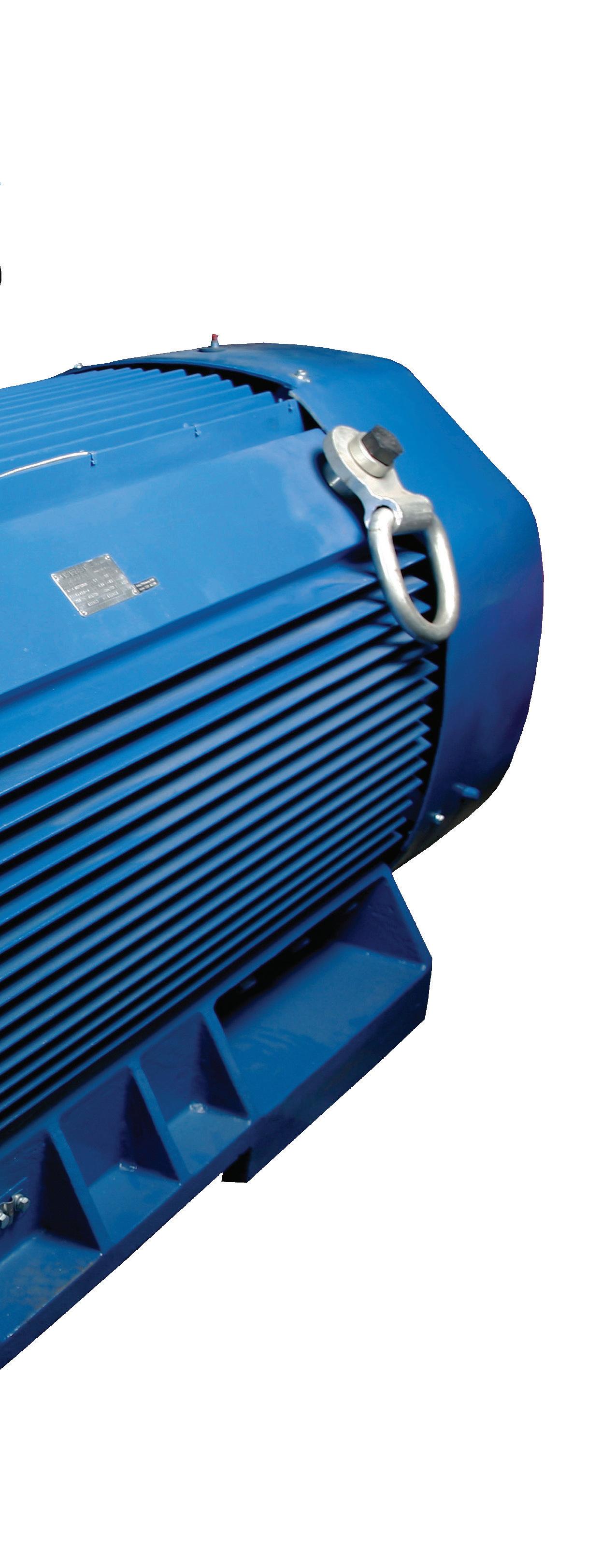
K-series
Technical description
IEC 80-560
Up to 3kW (4HP): 380-420 / 220-240 V Y/Δ 50Hz
From 4kW (5.5HP): 660-725 / 380-420 V Y/Δ 50Hz
Applications
Compressors
Marine duty
Standard features
Heavy duty design cast iron housing motor (feet integral with the casing)
IP55 protection degree
Insulation class F, temperature rise 80°C
Standard PTC protection in the winding (1 per phase series connected)
Standard oil seals in both DE and NDE sides
Top mounted terminal box (with the possibility of rotation by 180°)
SKF or NSK bearings
Regreasable bearings from frame size 160 and above
RAL 5010, blue color
Optional features
Special voltages and frequency
Class H insulation
Brake up to frame 280
Forced cooling for constant torque operation
through frequency inverter
IP56 / IP65 protection
Right or Left-hand side terminal box
PT100 in the winding and bearings
Frame reduced motors (non-IEC)
Drip cover (canopy) for shaft down applications
Anticondensation heaters
Insulated bearing
Roller bearings on drive end
Double shaft
Epoxy raisin encapsulated terminal box
Epoxy raisin encapsulated winding
Silicon encapsulated terminal box
Cable execution (with terminal box or directly connected)
Additional terminal box
K-series
Three-phase motors with squirrel cage, protection degree IP55
38
2 POLES-3.000 Rpm 380-420/220-240 V Y/Δ 50 Hz 660-725/380-420 V Y/Δ 50 Ηz Insulation class F TYPE Power Speed Efficiency Power Factor Rated current (400V) Nominal Torque Moment of inertia GD²/4 Starting current ratio Starting Torque ratio Breakdown Torque Net Weight KW HP RPM % συνφ A Nm kgm2 Ip/In Mp/Mn Mm/Mn kg K80-2 0,75 1 2830 75,8 0,83 1,7 2,5 0,0008 7,0 3,10 2,90 13 K80-2 1,1 1,5 2830 76,1 0,84 2,5 3,7 0,0009 6,7 2,90 3,00 15 K90S-2 1,5 2 2840 79,3 0,84 3,3 5,0 0,0012 6,8 3,00 3,00 20 K90L-2 2,2 3 2840 81,5 0,85 4,6 7,4 0,0015 6,9 3,40 2,90 23 K100L-2 3 4 2860 82,7 0,87 6,0 10 0,0030 7,2 2,90 2,90 3O Κ112Μ-2 4 5,5 2880 85,3 0,88 7,7 13 0,0050 6,9 2,38 3,07 40 Κ132S-2 5,5 7,5 2900 89,4 0,88 10,1 18 0,0100 7,0 2,30 2,85 54 Κ132S-2 7,5 10 2900 88,6 0,88 13,9 25 0,0120 6,8 2,27 3,08 60 K160M-2 11 15 2930 89,4 0,88 20,2 36 0,0300 7,3 2,40 3,09 99 K160M-2 15 20 2930 91,2 0,89 27 49 0,0450 7,1 2,27 3,07 110 K160L-2 18,5 25 2930 92,7 0,89 32 60 0,0550 6,8 2,29 2,70 127 K180M-2 22 30 2940 91,0 0,9 39 71 0,0760 7,6 3,10 3,14 167 K200L-2 30 40 2940 90,7 0,9 53 97 0,1240 7,2 2,86 3,09 220 K200L-2 37 50 2950 91,6 0,89 66 120 0,1390 7,2 2,80 2,92 242 K225M-2 45 60 2970 93,1 0,9 78 145 0,2330 7,1 2,98 3,04 281 K250M-2 55 75 2970 92,2 0,9 96 177 0,3120 7,3 2,39 3,01 373 K280S-2 75 100 2970 95,0 0,9 127 241 0,5970 6,2 2,20 2,70 477 K280M-2 90 125 2970 94,2 0,91 152 289 0,6750 6,2 2,10 2,60 516 K315S-2 110 150 2980 95,2 0,91 184 353 1,1400 7,1 2,32 2,81 792 K315M-2 132 180 2980 95,8 0,91 219 423 1,1900 6,6 2,32 2,68 828 K315L-2 160 220 2980 96,2 0,92 261 513 1,7600 6,9 2,17 2,87 932 K315L-2 200 270 2980 95,3 0,92 330 641 2,0200 6,5 2,29 2,91 1.044 K355M-2 250 340 2980 95,9 0,92 409 801 3,5600 6,6 2,20 2,88 1.638 K355L-2 315 430 2980 97,0 0,92 510 1.009 3,8490 7,8 1,70 4,10 1.798 K355L-2 355 480 2975 96,0 0,89 600 1.140 4,12 5,4 1,61 2,70 1.834 Κ400-2 400 540 2975 96,0 0,91 660 1.284 5,80 7,7 1,71 2,90 3.000 Κ400-2 450 600 2975 96,3 0,91 741 1.445 5,90 6,8 1,60 2,00 3.100 Κ400-2 500 680 2975 96,3 0,92 815 1.605 6,40 6,8 1,60 2,00 3.150 Κ400-2 560 760 2980 96,4 0,92 911 1.795 8,60 7,0 1,50 2,00 3.200 Κ400-2 630 850 2980 96,4 0,92 1025 2.019 9,60 7,0 1,50 2,00 3.500 Κ400-2 710 965 2980 96,5 0,92 1159 2.275 11,00 7,0 1,50 2,00 3.660 K450-2 800 1090 2985 96,5 0,92 1306 2.559 19,00 7,0 1,00 2,00 4.400 K450-2 900 1225 2985 96,7 0,92 1466 2.879 21,00 7,0 1,00 2,00 4.650 K450-2 1000 1360 2985 96,7 0,92 1629 3.199 23,00 7,0 1,00 2,00 4.950
K-series
Three-phase motors with squirrel cage, protection degree IP55
39
4 POLES-1.500 Rpm 380-420/220-240 V Y/Δ 50 Hz 660-725/380-420 V Y/Δ 50 Ηz Insulation class F TYPE Power Speed Efficiency Power Factor Rated current (400V) Nominal Torque Moment of inertia GD²/4 Starting current ratio Starting Torque ratio Breakdown Torque Net Weight KW HP Rpm % συνφ Αmp Nm Kgm² Ip/In Mp/Mn Mm/Mn Kg K80-4 0,55 0,75 1390 69,2 0,75 1,5 3,8 0,0018 5,1 2,40 2,80 13 K80-4 0,75 1 1390 74,5 0,76 1,9 5,2 0,0021 4,9 3,00 2,70 15 K90S-4 1,1 1,5 1390 74,4 0,77 2,8 7,6 0,0021 5,4 2,50 2,50 20 K90L-4 1,5 2 1390 77,5 0,79 3,5 10,3 0,0027 5,9 3,20 2,60 24 K100L-4 2,2 3 1410 80,5 0,81 4,9 15 0,0054 6,6 2,70 2,80 29 K100L-4 3 4 1410 81,3 0,82 6,5 20 0,0067 6,5 2,70 2,90 32 Κ112Μ-4 4 5,5 1435 80,1 0,82 8,8 27 0,0086 6,8 2,40 3,20 42 Κ132S-4 5,5 7,5 1440 86,3 0,83 11,1 36 0,021 7,4 2,20 3,50 57 Κ132M-4 7,5 10 1440 93,6 0,81 14,3 50 0,029 7,7 2,60 3,50 69 K160M-4 11 15 1460 89,3 0,84 21,2 72 0,075 7,3 2,37 2,90 107 K160L-4 15 20 1485 91,5 0,84 28,2 96 0,092 8 2,55 3,50 129 K180M-4 18,5 25 1465 91,2 0,86 34 121 0,139 6,9 2,13 3,09 162 K180L-4 22 30 1470 92,0 0,86 40 143 0,158 7,6 2,59 3,27 172 K200L-4 30 40 1480 92,0 0,86 55 194 0,262 6,3 2,01 2,61 224 K225S-4 37 50 1480 93,0 0,87 66 239 0,406 7 2,2 2,97 277 K225M-4 45 60 1480 94,3 0,87 79 290 0,469 6,7 1,84 2,80 302 K250M-4 55 75 1480 94,1 0,87 97 355 0,660 6 2,3 2,54 383 K280S-4 75 100 1480 94,9 0,87 131 484 1,120 6,5 2,4 2,80 527 K280M-4 90 125 1480 97,1 0,87 154 581 1,460 7,1 2,5 2,90 548 K315S-4 110 150 1490 96,5 0,88 187 705 3,110 6,5 2,21 2,91 850 K315M-4 132 180 1490 95,4 0,88 227 846 3,290 5,7 1,88 2,56 918 K315L-4 160 220 1490 95,4 0,89 272 1.026 3,790 6,9 2,28 2,72 1.018 K315L-4 200 270 1490 96,4 0,89 337 1.282 4,490 5,7 2,1 2,70 1.122 K355M-4 250 340 1490 96,0 0,9 418 1.602 5,670 7,2 2,29 2,89 1.650 K355L-4 315 430 1490 97,8 0,9 517 2.019 8,702 5,3 2,11 2,49 1.804 K355L-4 355 480 1490 96,0 0,89 600 2.275 11,2 7,8 2,3 3,4 2.083 K400-4 400 540 1490 96,0 0,88 682 2.564 14,9 6,2 1,33 3,58 3.000 K400-4 450 610 1490 96,0 0,90 753 2.884 15,1 6,7 1,25 3,35 3.050 K400L-4 500 680 1490 96,2 0,89 846 3.205 18,4 6,3 1,22 3,16 3.300 K400-4 560 760 1490 96,0 0,89 946 3.589 19,5 7,4 1,74 3,92 3.400 K400-4 630 850 1485 96,2 0,9 1052 4.052 21,1 5,8 1,32 2,8 3.500 K400-4 710 965 1490 96,0 0,9 1181 4.551 21,8 7,0 1,47 3,55 3.600 K450-4 800 1090 1490 96,6 0,89 1349 5.128 33,8 7,0 1,2 2 4.700 K450-4 900 1225 1490 96,8 0,89 1514 5.768 36,9 7,0 1,2 2 4.900 K450-4 1000 1360 1490 96,8 0,89 1682 6.409 41,9 7,0 1,2 2 5.150 K500-4 1120 1525 1490 97,0 0,9 1859 7.179 53,0 7,0 0,9 2 5.680 K500-4 1250 1700 1490 97,0 0,9 2075 8.012 59,0 7,0 0,9 2 5.820 K500-4 1400 1900 1490 97,0 0,9 2324 8.973 66,0 7,0 0,9 2 6.140
K-series
Three-phase motors with squirrel cage, protection degree IP55
40
6 POLES-1.000 Rpm 380-420/220-240 V Y/Δ 50 Hz 660-725/380-420 V Y/Δ 50 Ηz Insulation class F TYPE Power Speed Efficiency Power Factor Rated current (400V) Nominal Torque Moment of inertia GD²/4 Starting current Ratio Starting Torque Ratio Break down Torque Net Weight KW HP Rpm % συνφ Αmp Nm Kgm² Ip/In Mp/Mn Mm/Mn Kg K80-6 0,37 0,5 890 61,4 0,70 1,2 4,0 0,0016 3,5 2,00 2,80 15 K80-6 0,55 0,75 890 64,1 0,72 1,7 5,9 0,0021 3,0 2,11 2,29 16 K90S-6 0,75 1 910 68,4 0,72 2,2 7,9 0,0029 4,6 2,90 2,70 21 K90L-6 1,1 1,5 910 71,1 0,73 3,1 11,5 0,0035 4,6 2,60 2,60 23 K100L-6 1,5 2 920 75,5 0,75 3,8 15,6 0,0069 4,8 2,00 2,10 29 K112M-6 2,2 3 935 79,5 0,76 5,3 22,5 0,0129 5,3 1,50 2,40 37 K132S-6 3 4 960 86,4 0,76 6,6 30 0,0274 6,4 2,10 3,20 52 K132M-6 4 5,5 960 86,4 0,76 8,8 40 0,0343 7,0 1,80 3,60 59 K132M-6 5,5 7,5 960 86,0 0,77 12 55 0,0431 7,5 2,10 4,00 72 K160M-6 7,5 10 970 87,4 0,78 15,9 74 0,0880 6,1 2,27 2,76 98 K160L-6 11 15 970 89,8 0,77 23 108 0,1160 6,0 2,28 2,83 121 K180L-6 15 20 970 91,0 0,81 29 148 0,2070 6,6 2,36 2,93 164 K200L-6 18,5 25 970 93,0 0,81 36 182 0,3150 6,7 2,68 2,71 208 K200L-6 22 30 970 93,7 0,83 41 217 0,3600 6,4 2,60 2,72 217 K225M-6 30 40 980 91,8 0,84 56 292 0,5470 6,8 2,59 2,69 287 K250M-6 37 50 980 94,8 0,86 66 361 0,8340 6,0 2,15 2,40 355 K280S-6 45 60 980 93,6 0,86 81 439 1,3900 6,2 1,89 2,44 456 K280M-6 55 75 980 95,4 0,86 97 536 1,6500 6,2 1,80 2,50 502 K315S-6 75 100 990 93,9 0,86 134 723 4,1100 6,4 2,11 2,83 786 K315M-6 90 125 990 94,3 0,86 160 868 4,2800 6,9 1,94 2,84 884 K315L-6 110 150 990 94,4 0,86 196 1.061 5,4500 6,5 2,20 2,80 964 K315L-6 132 180 990 94,6 0,87 232 1.273 6,1200 6,5 1,95 2,86 1 060 K355M-6 160 220 990 95,1 0,88 276 1.543 8,8500 6,3 2,09 2,98 1 554 K355M-6 200 270 990 95,5 0,88 344 1.929 10,7620 7,0 1,70 3,40 1 768 K355L-6 250 340 990 95,4 0,88 430 2.412 12,8000 7 1,7 3,3 1 902 K400-6 315 430 990 95,8 0,88 537 3.039 18 6,5 1,42 3,17 3.500 K400-6 355 480 990 96,2 0,88 606 3.424 19 6,6 1,2 3,4 3.600 K400-6 400 540 990 95,5 0,88 688 3.859 21,7 7,2 1,4 1,3 3.800 K400-6 450 610 990 95,8 0,89 759 4.341 22 6,5 1,1 3,2 3.870 K400-6 500 680 990 95,5 0,86 880 4.823 23,4 7,1 1,7 3,7 4.000 K400-6 560 760 985 95,7 0,87 976 5.429 24 7,1 1,5 3,9 4.100 K450L-6 630 850 995 96,7 0,85 1110 6.046 45,1 6,5 1,4 1,8 4.700 K450L-6 710 965 995 96,7 0,85 1251 6.814 48,6 6,5 1,4 1,8 5.100 K450L-6 800 1090 995 96,7 0,85 1410 7.678 54,2 6,5 1,4 1,8 5.500 Κ500-6 900 1225 995 97 0,86 1563 8.638 68,5 6,5 1 1,8 5.800 Κ500-6 1000 1360 995 97 0,86 1737 9.598 72,1 6,5 1 1,8 6.100 Κ500-6 1120 1525 995 97 0,86 1945 10.750 75,3 6,5 1 1,8 6.250 Κ560-6 1250 1700 995 97 0,86 2171 11.997 80,5 6,5 0,8 1,8 6.900 Κ560-6 1400 1900 995 97 0,86 2432 13.437 84,6 6,5 0,8 1,8 7.150
K-series
Three-phase motors with squirrel cage, protection degree IP55
41
8 POLES-750 Rpm 380-420/220-240 V Y/Δ 50 Hz 660-725/380-420 V Y/Δ 50 Ηz Insulation class F TYPE Power Speed Efficiency Power factor Rated current (400V) Nominal torque Moment of inertia GD²/4 Starting current ratio Starting torque ratio Breakdown torque Net weight KW HP Rpm % συνφ Αmp Nm Kgm² Ip/In Mp/Mn Mm/Mn Kg K80-8 0,18 0,25 630 49,5 0,61 0,86 2,7 0,0016 2,9 2,50 3,20 15 K80-8 0,25 0,33 640 56,3 0,61 1,05 3,7 0,0021 2,8 2,40 3,10 17 K90S-8 0,37 0,5 660 61,1 0,61 1,43 5,4 0,0029 3,5 2,30 3,10 21 K90L-8 0,55 0,75 660 61,9 0,61 2,10 8,0 0,0035 3,7 2,20 2,60 24 K100L-8 0,75 1 690 70,5 0,67 2,30 10,4 0,0063 3,9 2,30 2,90 28 K100L-8 1,1 1,5 690 73,0 0,69 3,16 15,2 0,0077 4,0 2,80 2,80 33 K112M-8 1,5 2 680 74,6 0,69 4,21 21,1 0,0138 4,8 2,30 3,10 45 K132S-8 2,2 3 710 78,0 0,71 5,7 30 0,0290 5,2 1,90 2,90 51 K132M-8 3 4 710 78,6 0,73 7,6 40 0,0380 5,2 2,00 3,10 61 K160M-8 4 5,5 720 81,6 0,73 9,7 53 0,0649 5,3 1,80 2,90 89 K160M-8 5,5 7,5 720 83,3 0,74 12,9 73 0,0821 6,0 2,10 3,20 107 K160L-8 7,5 10 720 86,0 0,75 16,8 99 0,1140 6,0 2,10 3,30 120 K180L-8 11 15 730 87,9 0,76 23,8 144 0,1670 6,4 2,10 3,00 158 K200L-8 15 20 730 88,3 0,76 32 196 0,3250 6,3 2,20 2,90 228 K225S-8 18,5 25 730 90,4 0,76 39 242 0,4810 6,6 2,20 2,80 258 K225M-8 22 30 740 91,2 0,78 45 284 0,5310 7,1 2,20 3,00 282 K250M-8 30 40 740 91,5 0,79 60 387 0,8090 6,0 2,00 3,00 367 K280S-8 37 50 740 92,0 0,79 74 478 1,3810 5,7 2,10 2,80 468 K280M-8 45 60 740 92,5 0,79 89 581 1,7210 5,8 2,10 2,90 515 K315S-8 55 75 740 93,4 0,81 105 710 4,5900 5,0 1,60 2,90 752 K315M-8 75 100 740 93,4 0,81 143 968 5,3600 6,1 2,00 2,80 870 K315L-8 90 125 740 94,2 0,82 168 1.161 6,1100 6,3 1,80 2,90 976 K315L-8 110 150 740 94,5 0,82 205 1.420 6,5500 6,4 1,70 3,10 1.096 K355M-8 132 180 740 94,3 0,82 247 1.704 12,8550 6,5 1,80 3,10 1.556 K355M-8 160 220 740 94,6 0,82 298 2.065 14,3400 6,7 1,80 3,40 1.704 K355L-8 200 270 740 94,9 0,83 367 2.581 15,8240 6,0 1,70 3,10 1.989 K400-8 250 340 740 95,1 0,80 473 3.226 25,4 6,8 1,4 3,8 3.200 K400-8 315 430 740 95,5 0,86 557 4.065 27,5 6,1 1 2,9 3.250 K400-8 355 480 740 95,5 0,82 651 4.581 29,2 5,9 1,3 3 3.300 K400-8 400 540 745 95,2 0,81 747 5.128 31,1 5,7 1,2 3 3.350 K400-8 450 610 740 95,6 0,8 852 5.807 29 6 1,5 1,8 3.760 K450-8 500 680 745 95,8 0,8 945 6.409 44,1 5,6 1,2 1,8 4.750 K450-8 560 760 745 95,8 0,8 1058 7.179 49,5 5,6 1,2 1,8 5220 K450-8 630 850 745 96 0,8 1188 8.076 54,8 5,6 1,2 1,8 5600 Κ500-8 710 965 745 96 0,81 1323 9.101 70,1 5,6 1 1,8 5750 Κ500-8 800 1090 745 96,2 0,81 1487 10.255 73,2 5,6 1 1,8 5950 Κ500-8 900 1225 745 96,2 0,81 1673 11.537 76,8 5,6 1 1,8 6150 Κ560-8 1000 1360 745 96,5 0,81 1854 12.819 81,8 5,6 0,8 1,8 6850 Κ560-8 1120 1525 745 96,8 0,81 2070 14.357 84,1 5,6 0,8 1,8 7050 Κ560-8 1250 1700 745 97 0,81 2305 16.023 88,4 5,6 0,8 1,8 7300
K-series
Dimension sheet
42
MOUNTING B3 SIZE 80-355 TYPE H A B C AA AB BB AC HD HA KK K D E F GA DB L K80 80 125 100 50 34 160 130 175 230 10 M25x1.5 10 19 40 6 21.5 M6x16 295 K90S 90 140 100 56 36 180 135 190 260 12.5 M25x1.5 10 24 50 8 27 M8x19 320 K90L 125 160 345 K100L 100 160 140 63 40 200 182 215 270 14 M25x1.5 12 28 60 8 31 M10x22 385 K112M 112 190 140 70 45 230 195 236 310 14 M32x1.5 12 28 60 8 31 M10x22 415 K132S 132 216 140 89 52 265 208 275 350 16 M32x1.5 12 38 80 10 41 M12x28 490 K132M 178 245 520 K160M 160 254 210 108 65 320 260 330 425 19 M40x1.5 14.5 42 110 12 45 M16x36 610 K160L 254 305 655 K180M 180 279 241 121 74 350 297 380 460 22 M40x1.5 14.5 48 110 14 51.5 M16x36 680 K180L 279 335 720 K200L 200 318 305 133 75 395 370 420 515 25 M50x1.5 18.5 55 110 16 59 M20x42 760 K225S 225 356 286 149 75 436 355 465 560 28 M50x1.5 18.5 60 140 18 64 M20x42 825 K225M-2 311 380 55 110 16 59 820 K225M-4-6-8 311 60 140 18 64 850 K250M-2 250 406 349 168 88 495 440 520 620 33 M63x1.5 24 60 140 18 64 M20x42 925 K250M-4-6-8 65 69 K280S-2 280 457 368 190 109 550 535 570 685 35 M63x1.5 24 65 140 18 69 M20x42 970 K280S-4-6-8 368 75 20 79.5 Κ280Μ-2 419 535 65 18 69 1010 Κ280Μ-4-6-8 419 75 20 79.5 K315S-2 315 508 406 216 120 635 515 650 820 45 M63x1.5 28 65 140 18 69 M20x42 1160 K315S-4-6-8 80 170 22 85 1190 K315M-2 457 625 65 140 18 69 1270 K315M-4-6-8 80 170 22 85 1300 K315L-2 508 65 140 18 69 1270 K315L-4-6-8 80 170 22 85 1300 K355M-2 355 610 560 254 125 735 775 735 1000 49 M72x1.5 28 75 140 20 79.5 M24x50 1500 K355M-4-6-8 100 210 28 106 1570 K355L-2 630 75 140 20 79.5 M24x50 1500 K355L-4-6-8 100 210 28 106 1570
A VEW-A 2:1 L BB A K AB AA B EC DB F D GA AC H HA HD
2XKK
K-series
Dimension sheet
43
MOUNTING B5 SIZE 80-355 TYPE P N LA M T S Z D E F KK GA DB AD AC L K80 200 130 12 165 3,5 12 4 19 40 6 M25x1.5 21,5 M6x16 148 175 295 K90S 200 130 12 165 3,5 12 4 24 50 8 M25x1.5 27 M8x19 165 190 320 K90L 345 K100L 250 180 12 215 4 14.5 4 28 60 8 M25x1.5 31 M10x22 170 215 385 K112M 250 180 12 215 4 14.5 4 28 60 8 M32x1.5 31 M10x22 195 236 415 K132S 300 230 13 265 4 14.5 4 38 80 10 M32x1.5 41 M12x28 215 275 490 K132M 520 K160M 350 250 15 300 5 18.5 4 42 110 12 M40x1.5 45 M16x36 265 330 610 K160L 655 K180M 350 250 15 300 5 18.5 4 48 110 14 M40x1.5 51,5 M16x36 280 380 680 K180L 720 K200L 400 300 17 350 5 18.5 4 55 110 16 M50x1.5 59 M20x42 315 420 760 K225S 450 350 20 400 5 18.5 8 60 55 60 140 18 M50x1.5 64 M20x42 335 465 825 K225M-2 110 16 59 820 K225M-4-6-8 140 18 64 850 K250M-2 550 450 20 500 5 18.5 8 60 140 18 M63x1.5 64 M20x42 375 520 925 K250M-4-6-8 65 69 K280S-2 550 450 20 500 5 18.5 8 65 140 18 M63x1.5 69 M20x42 405 570 970 K280S-4-6-8 75 20 79,5 Κ280Μ-2 65 18 69 1010 Κ280Μ-4-6-8 75 20 79,5 K315S-2 660 550 24 600 6 24 8 65 140 18 M63x1.5 69 M20x42 500 650 1160 K315S-4-6-8 80 170 22 85 1190 K315M-2 65 140 18 69 1270 K315M-4-6-8 80 170 22 85 1300 K315L-2 65 140 18 69 1270 K315L-4-6-8 80 170 22 85 1300 K355M-2 800 680 25 740 6 24 8 75 140 20 M72x1.5 79,5 M24x50 645 735 1500 K355M-4-6-8 100 210 28 106 1570 K355L-2 75 140 20 79,5 M24x50 1500 K355L-4-6-8 100 210 28 106 1570 P GA AC SXZ AD N LA T A DB 2XKK M D E L F VEW-A 2:1 45°
K-series Dimension sheet
44 T P GA AC N A F D EC BB L B DB VEW-A 2:1 LA 2XKK T P GA AC N A F D EC BB L B DB VEW-A 2:1 LA 2XKK
MOUNTING B35 SIZE 80-355 TYPE H A B C AA AB BB AC HD HA KK K K80 80 125 100 50 34 160 130 175 230 10 M25x1.5 10 K90S 90 140 100 56 36 180 135 190 260 12.5 M25x1.5 10 K90L 125 160 K100L 100 160 140 63 40 200 182 215 270 14 M25x1.5 12 K112M 112 190 140 70 45 230 195 236 310 14 M32x1.5 12 K132S 132 216 140 89 52 265 208 275 350 16 M32x1.5 12 K132M 178 245 K160M 160 254 210 108 65 320 260 330 425 19 M40x1.5 14.5 K160L 254 305 K180M 180 279 241 121 74 350 297 380 460 22 M40x1.5 14.5 K180L 279 335 K200L 200 318 305 133 75 395 370 420 515 25 M50x1.5 18.5 K225S 225 356 286 149 75 436 355 465 560 28 M50x1.5 18.5 K225M-2 311 380 K225M-4-6-8 K250M-2 250 406 349 168 88 495 440 520 620 33 M63x1.5 24 K250M-4-6-8 K280S-2 280 457 368 190 109 550 535 570 685 35 M63x1.5 24 K280S-4-6-8 Κ280Μ-2 419 Κ280Μ-4-6-8 K315S-2 315 508 406 216 120 635 515 650 820 45 M63x1.5 28 K315S-4-6-8 K315M-2 457 625 K315M-4-6-8 K315L-2 508 K315L-4-6-8 K355M-2 355 610 560 254 125 735 775 735 1000 49 M72x1.5 28 K355M-4-6-8 K355L-2 630 K355L-4-6-8
45 H HA HD AB A K M 45° SXZ AA
sheet MOUNTING B35 SIZE 80-355 P N LA M T S Z D E F GA DB L TYPE 200 130 12 165 3,5 12 4 19 40 6 21.5 M6x16 295 K80 200 130 12 165 3,5 12 4 24 50 8 27 M8x19 320 K90S 345 K90L 250 180 12 215 4 14.5 4 28 60 8 31 M10x22 385 K100L 250 180 12 215 4 14.5 4 28 60 8 31 M10x22 415 K112M 300 230 13 265 4 14.5 4 38 80 10 41 M12x28 490 K132S 520 K132M 350 250 15 300 5 18.5 4 42 110 12 45 M16x36 610 K160M 655 K160L 350 250 15 300 5 18.5 4 48 110 14 51.5 M16x36 680 K180M 720 K180L 400 300 17 350 5 18.5 4 55 110 16 59 M20x42 760 K200L 450 350 20 400 5 18.5 8 60 140 18 64 M20x42 825 K225S 55 110 16 59 820 K225M-2 60 140 18 64 850 K225M-4-6-8 550 450 20 500 5 18.5 8 60 140 18 64 M20x42 925 K250M-2 65 69 K250M-4-6-8 550 450 20 500 5 18.5 8 65 140 18 69 M20x42 970 K280S-2 75 20 79.5 K280S-4-6-8 65 18 69 1010 Κ280Μ-2 75 20 79.5 Κ280Μ-4-6-8 660 550 24 600 6 24 8 65 140 18 69 M20x42 1160 K315S-2 80 170 22 85 1190 K315S-4-6-8 65 140 18 69 1270 K315M-2 80 170 22 85 1300 K315M-4-6-8 65 140 18 69 1270 K315L-2 80 170 22 85 1300 K315L-4-6-8 800 680 25 740 6 24 8 75 140 20 79.5 M24x50 1500 K355M-2 100 210 28 106 1570 K355M-4-6-8 75 140 20 79.5 1500 K355L-2 100 210 28 106 1570 K355L-4-6-8
K-series Dimension
46 MOUNTING B14 SIZE 80-132
MOUNTING B14 SIZE 80-132 TYPE P N M T S Z D E F GA DB KK AC AD L K80 120 80 100 3 M6 4 19 40 6 21.5 M6x16 M25x1.5 175 148 295 K90S 140 95 115 3 M8 4 24 50 8 27 M8x19 M25x1.5 190 165 320 K90L 345 K100L 160 110 130 3.5 M8 4 28 60 8 31 M10x22 M25x1.5 215 170 385 K112L 160 110 130 3.5 M8 4 28 60 8 31 M10x22 M32x1.5 236 195 415 K132S 200 130 165 3.5 M10 4 38 80 10 41 M12x28 M32x1.5 275 215 490 K132M 520 TYPE P N M T S Z D E F GA KK DB AC AD L K80 160 110 130 3.5 M8 4 19 40 6 21.5 M25x1.5 M6x16 175 148 295 K90S 160 110 130 3.5 M8 4 24 50 8 27 M25x1.5 M8x19 190 165 320 K90L 345 K100L 200 130 165 3.5 M10 4 28 60 8 31 M25x1.5 M10x22 215 170 385 K112L 200 130 165 3.5 M10 4 28 60 8 31 M32x1.5 M10x22 236 195 415 K132S 250 180 215 4 M12 4 38 80 10 41 M32x1.5 M12x28 275 215 490 K132M 520 T A GA AC AD N P E SXZ 45° M F VEW-A 2:1 DB L 2XKK D SMALL FLANGE B14 A LARGE FLANGE B14 B
K-series Dimension sheet
K-series
Dimension sheet
47 TYPE H A B1 B2 B3 B4 C AA AB K400 - 2 400 686 630 710 – – 280 120 806 K400 4-6-8 K450 - 2 450 800 900 1000 1120 1250 280 225 980 K450 4-6-8 K500 4-6-8 500 1000 1400 – – – 315 180 1080 K560 4-6-8 560 1000 1400 – – – 355 210 1170
VALIADIS DB D F EC B1 B2 B3 B4 BB L GA AC HA AA A K H HD AB TYPE BB AC HD HA K D E F DB L K400 - 2 1090 810 1090 45 35 80 170 22 M20 1841 K400 4-6-8 110m6 210 28 M24 1881 K450 - 2 1495 1035 1310 45 35 95 170 25 M24 2360 K450 4-6-8 120 210 32 2400 K500 4-6-8 1600 1095 1365 65 42 140 250 36 M24 2520 K560 4-6-8 1680 1195 1480 76 42 160 300 40 M24 2650 VALIADIS DB D F EC B1 B2 B3 B4 BB L GA AC HA AA A K H HD AB MOUNTING B3 SIZE 400-560
K-series
Dimension sheet
48
TYPE AA AB BB AC HD HA K D E F DB L K400 - 2 120 806 1090 810 1075 45 35 80 170 22 M20 1841 K400 4-6-8 110m6 210 28 M24 1881 K450 - 2 225 980 1495 1035 1310 45 35 95 170 25 M24 2360 K450 4-6-8 120 210 32 2400 K500 4-6-8 180 1080 1600 1095 1365 65 42 140 250 36 M24 2520 K560 4-6-8 210 1170 1680 1195 1480 76 42 160 300 40 M24 2650 TYPE P N M T S H A B1 B2 B3 B4 C K400 - 2 1000 880 940 6 8 28 400 686 630 710 – – 280 K400 4-6-8 K450 - 2 1000 880 940 6 8 28 450 800 900 1000 1120 1250 280 K450 4-6-8 K500 4-6-8 1150 1000 1080 6 8 28 500 900 1120 – – – 315 K560 4-6-8 1250 1120 1180 7 8 28 560 1000 1400 – – – 355 MOUNTING B35 SIZE 400-560 E HD H HA A AB S K AA AC L C B1 B2 BB T N P VALIADIS D F DB B3 B4 M
K-series
Dimension sheet
49
BEARINGS Frame Drive-End Non-Drive-End 2p 4,6,8p 2p 4,6,8p 80 6204ZZ C3 6204ZZ C3 6204ZZ C3 6204ZZ C3 90 6205ZZ C3 6205ZZ C3 6205ZZ C3 6205ZZ C3 100 6206ZZ C3 6206ZZ C3 6206ZZ C3 6206ZZ C3 112 6306ZZ C3 6306ZZ C3 6306ZZ C3 6306ZZ C3 132 6308ZZ C3 6308ZZ C3 6308ZZ C3 6308ZZ C3 160 6309C3 6309C3 6309C3 6309C3 180 6311C3 6311C3 6311C3 6311C3 200 6312C3 6312C3 6312C3 6312C3 225 6313C3 6313C3 6313C3 6313C3 250 6314C3 6314C3 6314C3 6314C3 280 6314C3 6317C3 6314C3 6317C3 315 6317C3 6319C3 or NU319 6317C3 6319C3 or NU319 355 6319C3 6322C3 or NU322 6319C3 6322C3 or NU322 400 6317C3 6326C3 or NU326 6317C3 6326C3 or NU326 450 6319C3 6328C3 or NU328 6319C3 6328C3 or NU328 500 6330C3 or NU330 6330C3 or NU330 560 6330C3 or NU330 6330C3 or NU330 AC VA LIADI S T F M E D GA DB SXZ N P LM L HD MOUNTING V1 SIZE 400-560 TYPE P N M T S D E F GA HD AC L LM K400-2 1000 880 940 6 8x ∅28 80 170 22 85 1275 865 1841 2161 K400-4-6-8 110m6 210 28 116 1881 2201 K450-2 1000 880 940 6 8x ∅28 95 170 25 100 1536 1035 2360 2710 K450-4-6-8 120 210 32 127 2400 2750 K500-4-6-8 1150 1000 1080 6 8x ∅28 140 250 36 148 1576 1095 2520 2850 K560-4-6-8 1250 1120 1180 7 8x ∅28 160 300 40 168 1681 1195 2650 3000
K-series
Three-phase motors with squirrel cage, protection degree IP55
4 / 2 POLES-1.500 / 3.000 Rpm
50 TYPE Power Speed Efficiency Power factor Rated current (400V) Starting current ratio Starting torque ratio Net weight KW Rpm % συνφ Αmp Ip/In Mp/Mn Kg K80-4/2 0,45/0,6 1380/2710 57,5/63,0 0,74/0,77 1,69/1,79 3,8/4,0 1,6/1,7 17 K80-4/2 0,6/0,8 1390/2750 59,7/63,8 0,78/0,91 2,12/2,09 3,8/4,5 1,6/1,8 18 K90S-4/2 1/1,3 1345/2730 63,3/64,9 0,78/0,92 3,31/3,40 3,5/4,5 1,8/1,8 22 K90L-4/2 1,4/1,9 1390/2790 75,1/70,6 0,82/0,91 3,25/4,00 4,8/5,4 2,1/2,3 28 K100L-4/2 2/2,4 1430/2850 74,5/73,6 0,80/0,90 4,81/5,22 5,4/6,3 1,9/2,0 34 K100LX-4/2 2,6/3,1 1410/2830 74,5/74,3 0,85/0,93 5,89/6,43 5,6/6,8 1,9/2,1 38 Κ112Μ-4/2 3,6/4,3 1440/2870 82,5/79,7 0,82/0,90 7,86/9,6 6,6/7,2 2,2/2,0 47 Κ132S-4/2 4,9/6 1425/2820 80,2/77,9 0,86/0,92 10,2/11,9 5,6/5,2 1,5/1,8 61 Κ132M-4/2 6,5/9 1430/2845 83,4/82,0 0,88/0,93 13,4/15,2 6,7/6,4 1,7/1,7 73 K160M-4/2 9/11 1450/2920 85,5/86,5 0,76/0,90 21,1/20,4 6,1/7,4 1,8/2,0 113 K160L-4/2 13/16 1440/2905 87,4/84,3 0,88/0,93 23,4/27,5 6,6/7,9 1,9/2,4 133 K180M-4/2 15/19 1460/2930 87,0/87,0 0,85/0,87 29,3/36,2 5,5/6,4 2,0/1,9 167 K180L-4/2 18,5/22 1460/2930 89,3/86,9 0,90/0,93 33,1/39,3 6,0/7,5 1,6/1,8 181 K200L-4/2 25/30 1465/2930 89,8/88,0 0,86/0,88 46,7/55,9 6,0/6,8 1,8/2,0 232 K225S-4/2 30/35 1465/2945 90,2/89,0 0,86/0,89 55,8/63,8 6,0/6,8 1,8/2,0 287 K225M-4/2 36/43 1465/2950 90,7/89,4 0,86/0,90 66,6/77,1 6,2/7,0 1,9/1,9 322 K250M-4/2 45/54 1470/2960 91,5/89,8 0,86/0,90 86,2/96,4 6,5/7,0 1,9/2,1 381 K280S-4/2 60/72 1470/2950 92,6/91,2 0,87/0,90 107/127 7,0/7,1 2,0/2,0 510 K280M-4/2 75/85 1470/2955 93,0/91,0 0,86/0,89 135/151 6,8/7,0 1,9/1,9 600 K315S-4/2 82/95 1475/2970 93,5/93,0 0,84/0,88 156/168 5,8/7,1 1,8/2,0 970 K315M-4/2 95/115 1480/2970 94,0/93,4 0,83/0,88 176/202 5,9/7,3 1,9/1,9 1.080 K315L-4/2 110/132 1480/2975 94,8/94,0 0,83/0,89 202/228 5,5/7,2 1,8/1,9 1.170 K315LX-4/2 135/165 1480/2975 94,7/93,5 0,82/0,88 251/289 5,7/7,2 1,9/1,8 1.210
CONSTANT
WINDING [Δ / YY] 380-420 V 50 Hz Insulation class F
TORQUE DAHLANDER
K-series
Three-phase motors with squirrel cage, protection degree IP55
51
4 / 2 POLES-1.500 / 3.000 Rpm
TORQUE DAHLANDER WINDING [Y / YY] 380-420 V 50 Hz Insulation class F TYPE Power Speed Efficiency Power factor Rated current (400V) Starting current ratio Starting torque ratio Net weight KW Rpm % συνφ Αmp Ip/In Mp/Mn Kg K80-4/2 0,18/0,7 1410/2875 52,0/64,0 0,65/0,77 0,77/2,05 3,5/5,5 1,6/2,2 16 K80-4/2 0,25/0,9 1440/2880 53,3/63,1 0,62/0,74 1,07/2,79 3,2/5,4 3,0/3,1 17 K90S-4/2 0,37/1,5 1420/2760 74,4/70,0 0,79/0,90 0,90/3,38 4,5/4,8 1,8/2,0 22 K90L-4/2 0,5/2 1445/2855 78,0/72,1 0,74/0,86 1,24/4,63 5,8/6,2 2,4/2,4 28 K100L-4/2 0,7/2,5 1425/2870 78,3/79,7 0,74/0,86 1,74/5,87 4,6/6,5 2,0/2,3 33 K100LX-4/2 0,8/3 1430/2875 73,8/75,9 0,71/0,81 2,48/8,45 4,9/5,6 2,2/1,9 36 Κ112Μ-4/2 1,1/4,1 1455/2870 85,0/79,7 0,82/0,90 2,48/9,57 6,6/7,2 1,6/2,0 47 Κ132S-4/2 1,5/5,5 1445/2900 81,8/83,7 0,78/0,90 3,38/10,5 5,3/5,9 1,9/2,3 62 Κ132M-4/2 2,2/9 1440/2880 83,4/85,7 0,78/0,91 4,90/15,1 5,2/7,4 1,9/2,2 85 K160M-4/2 3/12 1450/2920 85,5/86,5 0,76/0,90 7,33/22,2 6,1/7,4 1,8/2,0 117 K160L-4/2 4/16 1470/2920 87,1/89,3 0,73/0,89 9,71/30,7 6,1/8,1 2,5/2,5 134 K180M-4/2 5,5/20 1460/2930 87,0/87,0 0,85/0,87 10,7/38,1 5,5/6,4 2,0/1,9 167 K180L-4/2 6/24 1465/2925 88,8/87,1 0,90/0,93 11,6/42,5 5,3/6,7 1,9/1,8 185 K200L-4/2 8/30 1465/2930 89,8/88,0 0,86/0,88 14,6/55,9 6,0/6,8 1,8/2,0 232 K225S-4/2 10/37 1465/2950 89,9/89,4 0,86/0,89 17,7/67,1 6,5/7,2 1,9/2,0 287 K225M-4/2 12/45 1470/2950 91,2/89,5 0,85/0,89 22,3/81,5 7,0/7,8 2,0/2,1 322 K250M-4/2 15/55 1470/2960 91,5/89,8 0,86/0,90 27,5/98,2 6,5/7,0 1,9/2,1 381 K280S-4/2 20/75 1475/2970 91,8/90,0 0,86/0,89 36,6/135 7,0/7,5 1,9/2,2 510 K280M-4/2 24/90 1475/2970 92,2/90,5 0,85/0,90 44,2/159 7,0/7,6 2,0/2,2 600 K315S-4/2 27/110 1480/2975 94,0/93,0 0,83/0,90 53,7/190 5,8/7,0 1,8/2,0 970 K315M-4/2 33/132 1485/2970 94,3/93,6 0,78/0,90 68,7/226 5,1/6,8 1,8/1,9 1.080 K315L-4/2 40/145 1480/2975 94,8/94,0 0,83/0,89 73,4/250 5,5/7,2 1,8/1,9 1.170 K315LX-4/2 50/180 1480/2975 95,0/94,5 0,84/0,90 90,4/305 6,5/7,3 1,8/1,9 1.210
VARIABLE
K-series
Three-phase motors with squirrel cage, protection degree IP55
52
TYPE Power Speed Efficiency Power factor Rated current (400V) Starting current ratio Starting torque ratio Net weight KW Rpm % συνφ Αmp Ip/In Mp/Mn Kg K80-8/4 0,18/0,3 685/1405 42,0/67,7 0,60/0,82 1,02/0,78 2,6/4,8 2,4/2,3 17 K80-8/4 0,25/0,4 690/1390 51,1/71,4 0,62/0,85 1,11/0,94 2,6/4,2 1,6/1,7 19 K90S-8/4 0,35/0,55 690/1425 46,8/73,1 0,62/0,83 1,71/1,30 2,9/5,2 2,1/1,9 23 K90L-8/4 0,44/0,75 700/1405 57,1/73,6 0,58/0,87 1,90/1,69 3,2/4,9 2,2/1,9 25 K100L-8/4 0,7/1,1 705/1425 53,9/71,7 0,60/0,85 3,11/2,61 3,5/5,7 2,3/2,2 33 K100L-8/4 1/1,5 705/1415 84,9/56,9 0,63/0,43 3,37/3,26 3,9/5,7 1,9/1,8 37 K112M-8/4 1,4/2,2 700/1405 62,5/77,3 0,66/0,91 4,90/4,5 3,8/5,6 1,5/1,2 39 K132S-8/4 2,2/3,3 725/1455 73,4/82,9 0,65/0,89 6,65/6,4 5,3/7,3 1,4/1,6 71 K132M-8/4 2,6/4,2 725/1455 76,1/84,2 0,67/0,91 7,41/7,9 5,9/7,8 1,4/1,4 75 K160M-8/4 4,5/6,5 720/1440 80,0/85,1 0,73/0,91 12,3/14,5 5,3/6,2 1,4/1,5 108 K160L-8/4 6,5/9 715/1430 82,5/85,3 0,73/0,92 16,7/20,2 5,2/6,3 1,4/1,5 131 K180L-8/4 10/16 735/1475 86,1/89,2 0,66/0,90 25,5/28,8 6,4/8,5 2,4/1,9 171 K200L-8/4 14/22 720/1460 87,0/88,5 0,72/0,89 34,6/38,5 5,5/7,2 1,7/1,8 216 K225M-8/4 22/30 735/1475 90,8/90,3 0,79/0,92 44,5/52,2 5,2/7,2 1,8/2,1 292 K250M-8/4 28/38 730/1475 91,1/91,3 0,84/0,94 52,9/63,8 5,8/7,8 1,8/2,0 408 K280S-8/4 35/50 735/1475 90,9/90,2 0,81/0,92 68,5/86,7 5,8/7,5 1,8/2,0 465 K280M-8/4 45/60 735/1475 90,7/90,3 0,84/0,95 85,3/101 5,7/8,0 1,8/2,1 540 K315S-8/4 55/80 740/1485 92,0/91,5 0,81/0,90 107/140 6,5/7,8 1,9/2,1 940 K315M-8/4 70/100 740/1485 91,5/91,7 0,80/0,91 148/173 6,8/7,5 2,0/2,3 1.110 K315L-8/4 80/115 740/1485 92,5/92,0 0,80/0,90 156/200 6,8/7,4 2,0/2,3 1.175 K315L-8/4 100/140 740/1485 93,0/92,4 0,80/0,90 194/243 6,9/7,2 2,1/2,2 1.200 8 / 4 POLES-750 / 1.500 Rpm CONSTANT TORQUE DAHLANDER WINDING [Δ / YY] 380-420 V 50 Hz Insulation class F
K-series
Three-phase motors with squirrel cage, protection degree IP55
53
TYPE Power Speed Efficiency Power factor Rated current (400V) Starting current ratio Starting torque ratio Net weight KW Rpm % συνφ Αmp Ip/In Mp/Mn Kg K80-8/4 0,12/0,6 695/1410 41,5/65,2 0,53/0,76 0,75/1,72 2,3/4,5 2,8/2,4 17 K90S-8/4 0,3/1,3 705/1395 60,5/67,0 0,58/0,82 1,21/3,63 3,0/4,8 2,0/1,9 23 K100L-8/4 0,5/2 690/1420 59,6/73,2 0,65/0,80 2,18/5,34 2,8/5,4 1,3/2,3 34 K112M-8/4 1/4 695/1435 65,0/79,5 0,60/0,79 3,70/9,2 3,5/7,0 1,7/2,2 47 K132S-8/4 1,2/5 740/1445 82,2/83,7 0,68/0,84 3,09/10,2 4,6/7,1 1,7/2,0 65 K132M-8/4 1,8/6,5 725/1460 76,0/84,3 0,60/0,80 5,62/13,9 4,2/8,5 1,7/2,3 73 K160M-8/4 2,5/10 730/1450 83,0/83,2 0,66/0,86 6,60/20,2 6,1/8,3 2,2/2,6 106 K160L-8/4 3,5/12,5 730/1455 84,3/86,5 0,72/0,89 8,30/23,4 6,1/9,5 2,0/3,3 128 K180M-8/4 4/16 730/1470 85,5/89,5 0,69/0,86 11,0/29,9 4,0/8,1 1,4/2,1 170 K180L-8/4 5/20 725/1465 84,8/88,7 0,66/0,86 12,9/37,7 3,8/7,6 1,4/2,1 185 K200L-8/4 7/26 730/1475 87,4/90,4 0,68/0,87 17,4/47,5 4,1/8,6 1,6/2,7 239 K225S-8/4 9/35 735/1480 86,8/90,7 0,65/0,88 24,2/62,9 4,7/7,8 1,6/1,9 312 K225M-8/4 11/45 740/1480 88,3/91,7 0,67/0,89 29,3/79,6 4,4/7,5 1,5/2,0 330 K250M-8/4 14/50 735/1480 89,1/92,3 0,68/0,89 33,5/88,3 4,9/7,7 1,7/2,2 385 K280S-8/4 14/66 740/1480 87,0/90,5 0,67/0,86 44,6/117 5,5/7,7 2,0/2,3 465 K280M-8/4 20/78 740/1480 90,0/90,8 0,68/0,87 49,5/146 5,8/7,7 1,9/2,4 540 K315S-8/4 22/95 740/1485 90,9/91,5 0,70/0,88 54,4/170 6,5/7,8 1,9/2,4 921 K315M-8/4 26/110 740/1485 91,0/91,7 0,70/0,88 63,4/197 6,8/7,5 2,0/2,3 1.002 K315L-8/4 30/130 740/1485 91,5/92,0 0,71/0,89 77,8/238 6,8/7,4 2,0/2,3 1.070 K315L-8/4 38/160 740/1485 91,4/92,4 0,70/0,88 94,8/284 6,9/7,2 2,1/2,4 1.181 8 / 4 POLES-750 / 1.500 Rpm VARIABLE TORQUE DAHLANDER WINDING [Y / YY] 380-420 V 50 Hz Insulation class F
K-series
Three-phase motors with squirrel cage, protection degree IP55
54
/ 4 POLES-1.000 / 1.500 Rpm
50 Hz Insulation
TYPE Power Speed Efficiency Power factor Rated current (400V) Starting current ratio Starting torque ratio Net weight KW Rpm % συνφ Αmp Ip/In Mp/Mn Kg K80-6/4 0,2/0,28 920/1420 45,0/51,0 0,64/0,63 1,00/1,26 3,3/4,0 1,8/1,6 17 K80-6/4 0,25/0,37 930/1420 53,0/62,0 0,66/0,63 1,03/1,48 3,0/4,5 1,8/1,8 19 K90S-6/4 0,35/0,6 935/1430 64,0/70,0 0,72/0,76 1,10/1,63 3,5/5,0 1,8/1,7 23 K90L-6/4 0,5/0,9 940/1430 63,0/70,0 0,75/0,77 1,53/2,41 3,5/5,2 1,9/2,0 25 K100L-6/4 0,8/1,2 950/1435 73,5/75,0 0,76/0,80 2,07/2,89 3,9/5,5 2,0/1,9 34 K100LX-6/4 1/1,5 950/1435 74,0/75,0 0,74/0,81 2,64/3,80 4,2/5,5 1,9/2,0 38 Κ112Μ-6/4 1,5/2,2 950/1435 72,5/74,5 0,82/0,84 3,88/5,5 5,0/6,0 1,8/1,7 44 Κ132S-6/4 2/3,1 955/1440 73,5/74,5 0,84/0,85 4,68/7,1 5,5/6,0 1,7/1,9 61 Κ132M-6/4 3/4,3 955/1445 74,0/77,0 0,85/0,87 6,43/9,3 6,0/6,5 1,8/2,0 73 K160M-6/4 4,5/6,5 965/1450 77,5/80,0 0,83/0,90 10,1/13,8 6,8/7,0 1,7/1,8 113 K160L-6/4 6,5/9,5 965/1450 81,0/81,5 0,85/0,91 13,6/18,5 6,5/7,0 2,0/1,8 133 K180L-6/4 10/15 970/1455 83,5/83,0 0,87/0,90 18,9/27,1 6,7/7,0 1,7/1,8 181 K200L-6/4 13/19 970/1460 86,0/85,5 0,89/0,89 25,5/30,3 6,5/6,8 2,0/2,0 216 K200LX-6/4 15/20 970/1460 86,5/86,0 0,88/0,90 28,4/33,6 7,0/7,2 2,0/2,1 225 K225M-6/4 20/30 975/1465 89,0/89,0 0,90/0,92 36,0/45,8 7,0/7,1 2,0/1,9 292 K250M-6/4 25/35 980/1470 89,0/89,5 0,88/0,90 46,1/62,7 7,1/7,0 2,2/2,0 408 K280S-6/4 30/40 980/1480 89,5/90,0 0,88/0,89 55,0/72,1 7,2/7,4 2,2/2,0 465 K280M-6/4 37/45 980/1480 89,0/89,5 0,89/0,90 67,4/80,6 7,1/7,5 2,3/2,1 540 K315S-6/4 55/63 985/1485 90,5/90,0 0,87/0,89 101/114 7,2/7,2 2,1/1,8 861 K315M-6/4 65/80 990/1485 91,0/91,5 0,88/0,88 117/143 7,3/7,5 1,9/1,9 940 K315L-6/4 80/100 990/1485 91,5/91,0 0,87/0,89 145/178 7,1/7,6 2,0/2,8 1.110 K315LX-6/4 100/140 990/1485 91,5/91,0 0,88/0,88 179/252 7,0/7,6 2,0/1,9 1.175
6
CONSTANT TORQUE TWO SEPARATE WINDINGS 380-420 V
class F
K-series
Three-phase motors with squirrel cage, protection degree IP55
55 6 / 4 POLES-1.000 / 1.500 Rpm
TORQUE
VARIABLE
V 50 Hz Insulation class F
TWO SEPARATE WINDINGS 380-420
TYPE Power Speed Efficiency Power factor Rated current (400V) Starting curren ratio Starting torque ratio Net weight KW Rpm % συνφ Αmp Ip/In Mp/Mn Kg K80-6/4 0,2/0,5 965/1420 49,9/64,2 0,54/0,79 1,02/1,69 3,8/4,6 3,2/2,3 17 K90S-6/4 0,3/0,75 965/1435 59,5/61,6 0,61/0,74 1,36/3,13 3,9/5,2 2,1/2,1 23 K90L-6/4 0,4/1,1 935/1420 61,0/65,0 0,65/0,72 1,46/3,4 4,5/6,0 2,1/1,9 25 K100L-6/4 0,5/1,5 965/1435 70,5/79,5 0,66/0,86 2,29/3,5 4,5/6,8 2,2/2,0 34 K100LX-6/4 0,8/2,4 960/1420 70,8/78,3 0,70/0,87 2,31/5,04 4,5/6,0 2,0/2,1 38 Κ112Μ-6/4 1/3 965/1460 74,6/77,9 0,67/0,71 2,88/7,8 4,8/7,0 2,1/2,5 44 Κ132S-6/4 1,3/4,2 975/1460 79,3/82,7 0,66/0,81 4,07/9,7 5,9/6,5 2,0/1,9 61 Κ132M-6/4 1,5/5,5 975/1455 79,2/84,5 0,70/0,86 5,66/11,8 6,4/6,5 2,0/1,9 73 K160M-6/4 3/9 975/1465 82,7/86,0 0,68/0,79 8,40/21,1 6,7/7,7 2,4/2,1 113 K160L-6/4 3,5/12 980/1460 84,7/87,8 0,69/0,84 10,8/25,3 7,3/7,5 2,7/2,0 133 K180M-6/4 5/14 985/1475 82,2/89,2 0,68/0,85 13,9/30,5 6,6/7,9 2,5/2,2 181 K180L-6/4 6,5/18 985/1470 85,0/89,7 0,73/0,86 15,4/37,2 6,9/7,5 2,7/2,0 190 K200L-6/4 9/26 980/1475 86,6/90,4 0,79/0,87 19,0/47,7 6,2/7,8 2,2/2,2 232 K225S-6/4 10/31 985/1480 88,0/90,6 0,78/0,89 25,1/61,0 7,8/7,1 2,1/1,8 287 K225M-6/4 13/38 990/1475 88,0/90,3 0,77/0,89 29,8/71,8 7,7/7,3 2,8/2,0 322 K250M-6/4 17/48 990/1475 88,6/92,2 0,88/0,94 33,3/83,6 8,8/7,1 2,3/2,3 408 K280S-6/4 23/65 980/1475 86,0/91,4 0,87/0,89 44,4/121 7,5/7,0 2,1/1,9 465 K280M-6/4 27/80 985/1480 87,5/92,7 0,85/0,87 54,3/143 7,4/7,5 2,1/2,0 540 K315S-6/4 32/95 985/1480 87,8/93,1 0,81/0,88 69,0/167 7,0/7,2 2,0/1,8 1.002 K315M-6/4 37/115 985/1485 88,2/93,6 0,80/0,90 81,8/197 6,5/6,8 2,0/1,9 1.070 K315L-6/4 45/125 990/1485 88,9/93,8 0,89/0,80 91,3/216 6,8/7,0 1,9/1,8 1.181 K315LX-6/4 55/145 990/1485 90,9/94,0 0,81/0,89 108/250 6,9/7,1 2,0/1,8 1.250
K-series
Three-phase motors with squirrel cage, protection degree IP55 8 / 6 POLES-750 / 1.000 Rpm
56 TYPE Power Speed Efficiency Power factor Rated current (400V) Starting current ratio Starting torque ratio Net weight KW Rpm % συνφ Αmp Ip/In Mp/Mn Kg K90S-8/6 0,3/0,4 695/945 62 /68 0,61 /0,71 1,1 /1,2 2,5/4,5 1,4/1,6 25 K90L-8/6 0,4/0,6 695/945 61,9 /70,5 0,61 /0,72 1,5 /1,7 2,5/4,5 1,6/1,8 26 K100L-8/6 0,5/0,75 710/950 70,1 /75,1 0,66 /0,74 1,5 /1,9 3/5 1,5/1,7 38 K100L-8/6 0,7/0,9 710/950 70,5 /75,1 0,67 /0,74 2,1 /2,3 3,5/5,2 1,6/1,7 40 K112M-8/6 1/1,4 715/955 73,5 /79 0,68 /0,75 2,8 /3,4 3,6/6 1,8/2 50 K132S-8/6 1,5/2 715/960 78 /83,4 0,71 /0,75 3,9 /4,6 3,6/7 1,6/2,5 65 K132M-8/6 2,2/3 710/960 78 /83,4 0,71 /0,76 5,7 /6,8 4/7 1,7/2,3 80 K160M-8/6 4/5,5 720/960 81 /86,5 0,73 /0,77 9,8 /11,9 4/6,6 1,7/2,8 120 K160L-8/6 5,5/7,5 710/960 82,5 /86,7 0,73 /0,77 13 /16,2 3,8/7 1,9/3,2 145 K180L-8/6 8/11 720/960 88,3 /90 0,75 /0,8 17 /22,1 4/6,5 2/2,5 185 K200L-8/6 14/19 720/960 90,1 /92 0,76 /0,81 29 /36,9 4,5/6,5 2,2/2,4 250 K225S-8/6 17/20 720/960 91,3 /92,5 0,78 /0,83 34 /37,7 4,5/6,5 2,4/2,5 266 K225M-8/6 20/27 725/965 91,2 /91 0,78 /0,83 40 /51,8 4,5/6,5 2,1/2,3 300 K250M-8/6 24/32 725/965 91,5 /93,5 0,79 /0,86 48 /57,6 5/7,5 2,4/2,5 410 K280S-8/6 30/40 730/970 92 /93 0,79 /0,86 59 /72,4 6/7,5 2,4/2,5 530 K280M-8/6 40/50 735/970 92,3 /93 0,79 /0,86 79 /90,6 6,/7,2 2,2/2,4 600 K315S-8/6 50/60 735/980 94 /94 0,82 /0,86 94 /107,5 5,5/7,5 2/2,1 1.000 K315M-8/6 60/80 730/980 94 /94 0,82 /0,86 112 /143,4 5/6,5 1,2/1,5 1.100 K315M-8/6 70/90 730/980 94 /94 0,82 /0,86 131 /161,3 5/6,5 1,2/1,5 1.150 K315L-8/6 80/100 735/980 94 /94 0,82 /0,86 150 /179,2 5/7 1,2/1,5 1.230
CONSTANT TORQUE
SEPARATE WINDINGS
V 50 Hz Insulation class F
TWO
380-420
K-series
Three-phase motors with squirrel cage, protection degree IP55
57 8 / 6 POLES-750 / 1.000 Rpm VARIABLE TORQUE
SEPARATE WINDINGS 380-420 V 50 Hz Insulation class F
TWO
TYPE Power Speed Efficiency Power factor Rated current (400V) Starting current ratio Starting torque ratio Net weight KW Rpm % συνφ Αmp Ip/In Mp/Mn Kg K90L-8/6 0,3/0,75 695/920 48,4 /50,5 0,61 /0,73 1,5 /2,9 3/3,6 1,6/1,9 25 K100L-8/6 0,55/1,3 720/950 50,0 /56,2 0,67 /0,75 2,4 /4,5 3,1/3,7 1,8/1,5 33 K112M-8/6 0,7/1,9 720/950 52,3 /74,7 0,68 /0,76 2,9 /4,8 4/4,9 1,6/1,9 45 K132S-8/6 1,1/2,5 720/960 68,4 /71,6 0,7 /0,76 3,3 /6,7 4/6,1 1,3/2 63 K132M-8/6 1,5/3,8 720/960 63,1 /72,6 0,71 /0,76 4,8 /10 4/5,5 2/2,8 73 K160M-8/6 2,5/6 720/960 84,2 /89,3 0,73 /0,77 5,9 /12,6 6,2/6,4 2,4/1,8 120 K160L-8/6 3,5/7,5 720/960 90,1 /87,4 0,74 /0,77 7,6 /16,1 6/6,4 2/1,9 150 K180L-8/6 5,5/12 730/960 73,6 /84,7 0,76 /0,8 14,2 /25,6 5/5,5 1,6/1,3 200 K200L-8/6 9/20 730/960 86,0 /85,6 0,76 /0,81 20 /41,8 5,5/6,5 2,4/2,5 250 K225S-8/6 11/24 730/970 86,0 /88,2 0,78 /0,83 23,7 /47,5 5/6,5 2,3/2,8 280 K225M-8/6 13/27 730/970 89,6 /90,6 0,79 /0,83 26,6 /52 5/6,3 2,3/2,5 420 K250M-8/6 15/35 730/970 91,9 /93,2 0,79 /0,85 29,9 /64 5,5/6,5 2,3/2,2 408 K280S-8/6 22/45 730/970 94,4 /91,7 0,79 /0,85 42,7 /83,6 6,3/7 2,1/2 550 K280M-8/6 25/53 730/970 94,6 /95,1 0,79 /0,85 48,4 /95 6,3/7 2,4/2,3 600 K315S-8/6 33/70 730/980 95,3 /91,3 0,8 /0,86 62,7 /129,2 6,2/6,9 1,7/1,5 990 K315M-8/6 40/80 730/980 91,8 /88,6 0,81 /0,86 78 /152 6,2/6,9 1,7/1,5 1.080 K315M-8/6 45/100 735/980 94,1 /95,3 0,81 /0,86 86 /176,7 6,3/6,7 1,7/1,5 1.100 K315L-8/6 55/120 740/985 93,0 /92,5 0,82 /0,86 105 /218,5 6,5/7 1,7/1,5 1.200
K-series
Dimension sheet
58
TYPE X Y Z C D d K80 103 103 64 78 78 M5 K90 K100 110 110 71 86 86 M5 K112 K132 118 126 79 94 102 M5 K160 K180 160 170 91 134 144 M6 K200 K225 187 208 102 165 185 M8 K250 K280 217 246 115 193 222 M8 K315 330 380 222 290 342 M12 K355 348 477 285 60 158/158 M8 TERMINAL BOX DIMENSIONS FOR K SERIES SIZE 80-355 X Z W2 U2 V2 U1 V1 W1 Y D Ød C
59 BRAKE KITS FOR K (or AK) SERIES SIZE 80-250
E C B BB L TYPE L BRAKE TYPE Braking Torqe (N.m.) K80 364 AC4 with kit 20 K90S/L 417\442 AC5 with kit 40 K100 480 AC6 with kit 60 K112 510 AC7 with kit 90 K132S/M 580\618 AC8 Z20 with kit 200 K160M/L 750/794 AC8D 400 K180M/L 864/902 T180D 500 K200L 997 T200D 600 K225S/M-2/M4-8 1052/1047/1077 T200D 600 K250M 1117 K10 500-800
K-series Dimension sheet
K-series
60 TYPE L L1 L2 H D K-80 168 15 38 7 153 K-90 198 10 10 6 173 K-100 198 15 10 6 193 K-112 210 21 10 6 217 K-132 235 22 10 6 256
Dimension sheet FORCED COOLING KIT FOR K (or AK) SERIES SIZE 80 - 132 ∅ D L1 L H L2
K-series
Dimension sheet
61
TYPE L L1 L2 L3 D d H K-160 280 20 38 12 311 20 7 K-180 335 40 67.5 14 352 20 8 K-200 372 40 66 14 394 30 8 K-225 395 45 71.5 18 442 30 10 K-250 423 55 81.5 18 481 30 10 K-280 500 69 91.5 18 543 30 10 K-315 595 75 150 25 619 30 12 K-355 587 101 127 13 698 19 12
FOR K SERIES SIZE 160 - 355 395 L L1 H L3 ∅ D L2 ∅d 395 L L1 H L3 ∅ D L2 ∅d
FORCED
COOLING KIT
62 a/a MOTOR TYPE A AA H B C F D D1 1 80 56 20 19 36 20 31 M4 10 2 90-100 58 24 22 35 22 25 M4 12 3 112-132 66 24 24 40 24 31 M5 12 4 160-180 93 30 30 57 30 36 M6 12 5 200-225 114 38 38 68 38 44 M8 16 6 250-280 131 43 42 87 42 61 M10 16 7 315 172 56 54 119 54 80 M12 18 8 355 240 80 96 172 79 100 M16 25 C D H F Â ÁÁ Á D1 W2 U2 V2 U1 V1 W1
TERMINAL PLATE SIZE 80-335
K-series Dimension sheet
K-series
Dimension sheet
63 MOTOR TYPE Ø D Ø a Ø b Ø c Ø d Ø e L B C H T N K80-2,4,6 19.2 27 85 100 38 85 28 22 6 6 16 5 K90-2 24.2 32 110 135 50 115 35 27 6 8 20.5 5 K90-4,6,8 24.2 32 130 155 50 136 40 27 6 8 20.5 7 K100-2,4,6 28.2 36 130 155 54 136 40 27 6 8 24.5 5 K112-2 28.2 36 130 155 54 136 40 30 6 8 24.5 5 K112-4,6,8 28.2 36 150 185 54 160 45 30 6 8 24.5 7 K132-2 38.2 48 150 185 66 160 47 35 12 10 33.5 5 K132-4,6,8 38.2 48 165 200 66 175 50 35 12 10 33.5 7 K280-2 68 83 280 280 110 110 60 35 18 61.3 5 K280-4,6,8,10 68 95 400 400 130 130 65 35 20 61.3 9
FANS SIZE 80-132, 280 L C B H N T Ø c Ø b Ø a Ø D Ø d Ø e
64
MOTOR TYPE Ø D1 Ø D2 Ø a Ø b Ø c L B H T C K160-2 43 +0.26 -0.05 43 +0.18 -0.12 63 170 215 50 40 0 -0.62 12 +0.16 -0.06 38.3 0 -0.20 10 0 -0.18 K160-4.6 43 +0.26 -0.05 43 +0.18 -0.12 64 230 250 58 40 0 -0.62 12 +0.16 -0.06 38.3 0 -0.20 13 0 -0.18 K180-2,4 52 +0.28 0 52 +0.05 -0.13 72 200 250 65 35 0 -0.62 14 +0.16 -0.06 47 0 -0.20 10 0 -0.18 K180-6,8 52 +0.28 0 52 +0.05 -0.13 72 220 275 63 35 0 -0.62 14 +0.16 -0.06 47 0 -0.20 11 0 -0.18 K200-2,4 58 +0.28 0 58 +0.05 -0.13 94 210 260 75 40 0 -0.62 16 +0.18 0 52 0 -0.20 10 0 -0.18 K200-6,8 58 +0.28 0 58 +0.05 -0.13 94 240 295 75 40 0 -0.62 16 +0.18 0 52 0 -0.20 11 0 -0.18 K225-2 62 +0.07 -0.15 62 +0.07 -0.15 92 190 250 78 45 0 -0.62 16 +0.18 0 56 0 -0.20 6 0 -0.12 K225-4,6,8 62 +0.07 -0.15 62 +0.07 -0.15 92 280 350 90 45 0 -0.62 18 +0.18 0 55 0 -0.20 20 0 -2.1 K250-2 68 +0.30 0 68 +0.07 -0.15 104 220 250 80 45 0 -0.62 18 +0.18 0 61 0 -0.20 4 0 -0.12 K250-4,6,8 68 +0.30 0 68 +0.07 -0.15 104 280 350 90 45 0 -0.62 18 ± 0.215 61 0 -0.20 22 0 -2.1 K315-2 75 +0.046 0 75 +0.57 -0.11 118 290 350 110 60 0 -0.19 18 +0.21 0 79.4 +0.2 0 30 0 -0.12 K315-4 90 +0.11 -0.35 90 +0.57 -0.11 125 420 420 150 80 0 -0.74 22 +0.21 0 81.3 0 -0.2 35 0 -2.1 K355-2 75 +0.046 0 75 +0.57 -0.11 118 290 350 110 70 0 -0.19 20 -0.21 0 67.5 +0.2 0 30 0 -0.12 K355-4 90 +0.11 -0.35 90 +0.57 -0.11 145 450 570 110 70 0 -0.74 25 +0.21 0 81.3 0 -0.2 10 0 -2.1 FANS SIZE 160-355 H T Ø c Ø b Ø a CB D2 D1 L
K-series Dimension sheet
65 FANS SIZE 400 MOTOR TYPE Ø D Ø D1 Ø D2 F H L L1 L2 K400-2 410 132 90 +0.054 0 25± 0.026 96.4 +0.2 0 171±1 60 0 -0.19 95 0 -0.22 K400-4,6 500 159 110 +0.054 0 28± 0.026 116.4 +0.2 0 233±1 74 0 -0.19 145 0 -0.22 L F L1 L2 Ø D Ø D2 Ø D1 Ø D1 H
K-series Dimension sheet


VALIADIS S.A. VALIADIS S.A. VALIADIS S.A. VALIADIS S.A. VALIADIS S.A. VALIADIS S.A. VALIADIS S.A. VALIADIS S.A. VALIADIS S.A. VALIADIS S.A. VALIADIS S.A. VALIADIS S.A. VALIADIS VALIADIS S.A. VALIADIS S.A. VALIADIS S.A. VALIADIS S.A. VALIADIS S.A. VALIADIS S.A. VALIADIS S.A. VALIADIS S.A. VALIADIS
AK series


AK-series
Technical description
IEC 56-132
Up to 3kW (4HP):
380-420 / 220-240 V Y/Δ 50Hz
From 4kW (5.5HP):
660-725 / 380-420 V Y/Δ 50Hz
Applications
• Fans
• Pumps
• Gears
• Compressors
• Textiles
• Food industry
Standard features
• Industrial series of aluminium housing motors
• IP55 protection degree
• Insulation class F, temperature rise 80°C
• Removable feet with the possibility of right and left hand side terminal box
• Terminal box rotation at 180o
• SKF or NSK bearings
• Cast iron housing for the bearing
• RAL 5010, blue colour
Optional features
• Special voltages and frequency
• Class H insulation
• Brake kits for all motors
• Forced cooling for constant torque operation through frequency inverter
• IP56 / IP65 protection
• Cast iron flange / endshields
• PTC / PT100 in the winding
• Frame reduced motors (non-IEC)
• Anticondensation heaters
• Roller bearings on drive end
• Double shaft
• Cable execution (with terminal box or directly connected)
• Epoxy raisin encapsulated terminal box
• Epoxy raisin encapsulated winding
• Silicon encapsulated terminal box
AK-series
Three-phase motors with squirrel cage, protection degree IP55
70 TYPE Power Speed Efficiency Power factor Rated current (400V) Nominal torque Moment of inertia GD²/4 Starting current ratio Starting torque ratio Breakdown torque Net weight KW HP Rpm % συνφ Αmp Nm Mp/Mn Ip/In Mp/Mn Mm/Mn Kg AK56-2 0,09 0,12 2700 60,3 0,77 0,28 0,3 0,00013 6,0 2,2 2,2 4,6 AK56-2 0,12 0,16 2700 63,5 0,78 0,35 0,4 0,00014 6,0 2,2 2,2 4,8 AK63-2 0,18 0,25 2720 65,0 0,80 0,5 0,6 0,00018 6,5 2,2 2,2 5 AK63-2 0,25 0,33 2720 67,6 0,81 0,66 0,9 0,00019 6,5 2,2 2,2 5,3 AK71-2 0,37 0,5 2720 70,2 0,81 0,94 1,3 0,00030 7,0 2,2 2,2 6,5 AK71-2 0,55 0,75 2740 72,9 0,82 1,33 1,9 0,00035 7,0 2,2 2,3 7 AK80-2 0,75 1 2845 75,0 0,83 1,74 2,5 0,00075 7,5 2,2 2,3 9,5 AK80-2 1,1 1,5 2840 77,2 0,84 2,45 3,7 0,00090 7,9 2,2 2,3 11 AK90S-2 1,5 2 2840 79,2 0,84 3,26 5,0 0,00240 7,9 2,2 2,3 13 AK90L-2 2,2 3 2840 81,1 0,85 4,61 7,4 0,00280 7,9 2,2 2,3 16 AK100L-2 3 4 2860 83,2 0,87 5,99 10,0 0,00290 8,1 2,2 2,3 22 AK112Μ-2 4 5,5 2880 85,3 0,88 7,7 13,3 0,00550 8,1 2,2 2,3 30 AK132S-2 5,5 7,5 2900 86,0 0,88 10,5 18,1 0,01090 8,1 2,2 2,3 38 AK132S-2 7,5 10 2900 86,7 0,88 14,2 24,7 0,01260 8,1 2,2 2,3 42 AK132M-2 9 12,5 2890 86,1 0,89 16,9 29,7 0,01350 7,4 2,6 3,5 49
Y/Δ
Y/Δ 50
2 POLES-3.000 Rpm, 380-420/220-240 V
50 Hz 660-725/380-420 V
Ηz Insulation class F
AK-series
Three-phase motors with squirrel cage, protection degree IP55
71
POLES-1.500 Rpm, 380-420/220-240 V Y/Δ 50 Hz 660-725/380-420 V Y/Δ 50 Ηz Insulation class F TYPE Power Speed Efficiency Power factor Rated current (400V) Nominal torque Moment of inertia GD²/4 Starting current ratio Starting torque ratio Breakdown torque Net weight KW HP Rpm % συνφ Αmp Nm Kgm² Ip/In Mp/Mn Mm/Mn Kg AK56-4 0,06 0,08 1305 51,8 0,62 0,27 0,4 0,00013 5,2 2,1 2,2 4,6 AK56-4 0,09 0,12 1300 52,9 0,63 0,39 0,7 0,00014 5,2 2,1 2,2 4,8 AK63-4 0,12 0,16 1310 57,3 0,72 0,42 0,9 0,00027 5,2 2,4 2,2 4,8 AK63-4 0,18 0,25 1310 60,4 0,73 0,59 1,3 0,00032 5,2 2,4 2,2 5 AK71-4 0,25 0,33 1330 65,1 0,74 0,75 1,8 0,00045 5,2 2,4 2,2 6,3 AK71-4 0,37 0,5 1330 67,3 0,75 1,06 2,7 0,00051 5,2 2,4 2,2 7 AK80-4 0,55 0,75 1390 71,1 0,75 1,49 3,8 0,00180 5,7 2,4 2,3 9,5 AK80-4 0,75 1 1380 72,9 0,77 1,93 5,2 0,00210 6,5 2,3 2,3 11 AK90S-4 1,1 1,5 1390 75,1 0,77 2,75 7,6 0,00210 6,5 2,3 2,3 14,5 AK90L-4 1,5 2 1390 77,9 0,79 3,52 10,3 0,00270 6,5 2,3 2,3 16 AK100L-4 2,2 3 1410 80,1 0,81 4,9 14,9 0,00540 7,5 2,3 2,3 23 AK100L-4 3 4 1410 82,0 0,82 6,44 20,3 0,00670 7,5 2,3 2,3 27 AK112Μ-4 4 5,5 1435 84,3 0,82 8,36 26,6 0,00950 7,5 2,3 2,3 29 AK132S-4 5,5 7,5 1440 85,5 0,83 11,2 36,5 0,02140 7,5 2,3 2,3 40 AK132M-4 7,5 10 1440 87,2 0,84 14,8 49,7 0,02960 7,5 2,3 2,3 50 AK132M-4 9 12,5 1440 86,0 0,85 17,8 59,7 0,00350 7,8 2,6 3,3 58
4
AK-series
Three-phase motors with squirrel cage, protection degree IP55
72
POLES-1.000 Rpm 380-420/220-240 V Y/Δ 50 Hz 660-725/380-420 V Y/Δ 50 Ηz Insulation class F TYPE Power Speed Efficiency Power factor rated current (400V) Nominal torque Moment of inertia GD²/4 Starting current ratio Starting torque ratio Breakdown torque Net weight KW HP Rpm % συνφ Αmp Nm Kgm² Ip/In Mp/Mn Mm/Mn Kg AK71-6 0,18 0,25 850 56,0 0,66 0,76 2,0 0,00065 4,0 1,9 2 6 AK71-6 0,25 0,33 850 59,0 0,68 0,9 2,8 0,00074 4,0 1,9 2 6,3 AK80-6 0,37 0,5 890 62,0 0,70 1,23 4,0 0,00158 4,7 1,9 2 10 AK80-6 0,55 0,75 890 65,0 0,72 1,7 5,9 0,00210 4,7 1,9 2 11 AK90S-6 0,75 1 910 72,7 0,72 2,07 7,9 0,00290 5,9 2 2,1 13 AK90L-6 1,1 1,5 910 75,4 0,73 2,88 11,6 0,00350 5,9 2 2,1 14 AK100L-6 1,5 2 940 77,5 0,75 3,72 15,2 0,00690 5,9 2 2,1 23 AK112M-6 2,2 3 940 79,9 0,76 5,23 22,4 0,01380 6,9 2 2,1 25 AK132S-6 3 4 960 81,6 0,76 6,98 29,9 0,02860 6,9 2,1 2,1 28 AK132M-6 4 5,5 960 83,3 0,76 9,12 39,8 0,03570 6,9 2,1 2,1 45 AK132M-6 5,5 7,5 960 85,0 0,77 12,1 54,7 0,04490 6,9 2,1 2,1 55
6
AK-series
Three-phase motors with squirrel cage, protection degree IP55
73
8 POLES-750 Rpm 380-420/220-240 V Y/Δ 50 Hz 660-725/380-420 V Y/Δ 50 Ηz Insulation class F TYPE Power Speed Efficiency Power factor rated current (400V) Nominal torque Moment of inertia GD²/4 Starting current ratio Starting torque ratio Breakdown torque Net weight KW HP Rpm % συνφ Αmp Nm Kgm² Ip/In Mp/Mn Mm/Mn Kg AK80-8 0,18 0,25 640 55,0 0,61 0,77 2,7 0,00158 4,2 1,8 1,9 10 AK80-8 0,25 0,33 640 58,0 0,61 1,02 3,7 0,00210 4,2 1,8 1,9 11 AK90S-8 0,37 0,5 660 64,0 0,61 1,37 5,4 0,00290 4,5 1,8 1,9 13 AK90L-8 0,55 0,75 660 67,0 0,61 1,94 8,0 0,00350 4,5 1,8 2 14 AK100L-8 0,75 1 690 71,0 0,67 2,28 10,4 0,00690 5,5 1,8 2 23 AK100L-8 1,1 1,5 690 73,0 0,67 3,25 15,2 0,01070 5,5 1,8 2 25 AK112M-8 1,5 2 690 75,0 0,69 4,18 20,8 0,01490 5,5 1,8 2 28 AK132S-8 2,2 3 710 78,0 0,71 5,73 29,6 0,03140 6,9 1,8 2 45 AK132M-8 3 4 710 79,8 0,73 7,43 40,4 0,03950 6,9 1,8 2 55
AK-series
Dimension sheet
74
MOUNTING B3 SIZE 56-132 TYPE H A B C AA AB BB AC HD HA K D E F GA DB L AK56 56 90 71 36 25 110 90 121 154 8 M6 9 20 3 10,2 M3 192 AK63 63 100 80 40 34 120 110 121 165 8 M7 11 23 4 12,5 M4 210 AK71 71 112 90 45 36 132 120 137 180 9 M7 14 30 5 16 M5 250 AK80 80 125 100 50 41 152 132 156 205 10 M10 19 40 6 21,5 M6 280 AK90S 90 140 100 56 47 168 140 176 230 12 M10 24 50 8 27 M8 310 AK90L 125 165 335 AK100L 100 160 140 63 50 192 176 196 250 12 M12 28 60 8 31 M10 370 AK112M 112 190 140 70 60 222 180 220 280 14 M12 28 60 8 31 M10 395 AK132S 132 216 140 89 61 248 224 260 320 15 M12 38 80 10 41 M12 465 AK132M 178 495 L F D DB EC B BB AC HD H HA K AA A AB GA
AK-series
75 TYPE P N LA M T S Z D E F GA DB AD AC L AK56 120 80 9 100 3 7 4 9 20 3 10,2 M3 98 112 192 AK63 140 95 9 115 3 10 4 11 23 4 12,5 M4 102 121 210 AK71 160 110 10 130 3,5 10 4 14 30 5 16 M5 109 137 250 AK80 200 130 11 165 3,5 12 4 19 40 6 21,5 M6 125 156 280 AK90S 200 130 11 165 3,5 12 4 24 50 8 27 M8 140 176 310 AK90L 335 AK100L 250 180 14 215 4 15 4 28 60 8 31 M10 150 196 370 AK112M 250 180 14 215 4 15 4 28 60 8 31 M10 168 220 395 AK132S 300 230 16 265 4 15 4 38 80 10 41 M12 188 260 465 AK132M 495
Dimension
MOUNTING B5 SIZE 56-132 L ÁC ÁD S T P GA F DB N D E LA
sheet
AK-series
Dimension sheet
76
TYPE P N LA M T S Z H A B C AA AK56 120 80 9 100 3 7 4 56 90 71 36 25 AK63 140 95 9 115 3 10 4 63 100 80 40 34 AK71 160 110 10 130 3.5 10 4 71 112 90 45 36 AK80 200 130 11 165 3.5 12 4 80 125 100 50 41 AK90S 200 130 11 165 3.5 12 4 90 140 100 56 47 AK90L 125 AK100L 250 180 14 215 4 15 4 100 160 140 63 50 AK112M 250 180 14 215 4 15 4 112 190 140 70 60 AK132S 300 230 16 265 4 15 4 132 216 140 89 61 AK132M 178 MOUNTING B35 SIZE 56-132 L AC HD H LA T P N D E GA DB C F B BB
AK-series
77 MOUNTING B35 SIZE 56-132 AB BB AC HD HA K D E F GA DB L TYPE 110 90 112 154 8 M6 9 20 3 10.2 M3 192 AK56 120 110 121 165 8 M7 11 23 4 12.5 M4 210 AK63 132 120 137 180 9 M7 14 30 5 16 M5 250 AK71 152 132 156 205 10 M10 19 40 6 21.5 M6 280 AK80 168 140 176 230 12 M10 24 50 8 27 M8 310 AK90S 165 335 AK90L 192 176 196 250 12 M12 28 60 8 31 M10 370 AK100L 222 180 220 280 14 M12 28 60 8 31 M10 395 AK112M 248 224 260 320 15 M12 38 80 10 41 M12 465 AK132S 495 AK132M
Dimension sheet AC HD H HA AA A K S M AB
AK-series
Dimension sheet
78
MOUNTING B14 SIZE 56-132 TYPE P N M T S Z D E F GA DB AC AD L AK56 105 70 85 2.5 M6 4 9 20 3 10.2 M3 112 98 192 AK63 120 80 100 3 M6 4 11 23 4 12.5 M4 121 102 210 AK71 140 95 115 3 M8 4 14 30 5 16.1 M4 137 109 250 AK80 160 110 130 3.5 M8 4 19 40 6 21.5 M5 156 125 280 AK90S 160 110 130 3.5 M8 4 24 50 8 27 M8 176 140 310 AK90L 335 AK100L 200 130 165 3.5 M10 4 28 60 8 31 M8 196 150 370 AK112L 200 130 165 3.5 M10 4 28 60 8 31 M8 220 168 395 AK132S 250 180 215 4 M12 4 38 80 10 41 M12 260 188 465 AK132M 495 TYPE P N M T S Z D E F GA DB AC AD L AK56 80 50 65 2.5 M5 4 9 20 3 10.2 M3 112 98 192 AK63 90 60 75 2.5 M5 4 11 23 4 12.5 M4 121 102 210 AK71 105 70 85 2.5 M6 4 14 30 5 16.1 M4 137 109 250 AK80 120 80 100 3 M6 4 19 40 6 21.5 M5 156 125 280 AK90S 140 95 115 3 M8 4 24 50 8 27 M8 176 140 310 AK90L 335 AK100L 160 110 130 3.5 M8 4 28 60 8 31 M8 196 150 370 AK112L 160 110 130 3.5 M8 4 28 60 8 31 M8 220 168 395 AK132S 200 130 165 3.5 M10 4 38 80 10 41 M12 260 188 465 AK132M 495 LARGE FLANGE B14B SMALL FLANGE B14A L T P N D E F GA DB AC AD SxZ M
AK-series
Dimension sheet
79
TYPE P N M T S Z H A B AA AB BB AC HD HA K D E F GA DB L C AK56 80 50 65 2.5 M5 4 56 90 71 25 110 90 121 154 8 M6 9 20 3 10.2 M3 192 36 AK63 90 60 75 2.5 M5 4 63 100 80 34 120 110 121 165 8 M7 11 23 4 12.5 M4 210 40 AK71 105 70 85 2.5 M6 4 71 112 90 36 132 120 137 180 9 M7 14 30 5 16 M5 250 45 AK80 120 80 100 3 M6 4 80 125 100 41 152 132 156 205 10 M10 19 40 6 21.5 M6 280 50 AK90S 140 95 115 3 M8 4 90 140 100 47 168 140 176 230 12 M10 24 50 8 27 M8 310 56 AK90L 125 165 335 AK100L 160 110 130 3.5 M8 4 100 160 140 50 192 176 196 250 12 M12 28 60 8 31 M10 370 63 AK112M 160 110 130 3.5 M8 4 112 190 140 60 222 180 220 280 14 M12 28 60 8 31 M10 395 71 AK132S 200 130 165 3.5 M10 4 132 216 140 178 61 248 224 260 320 15 M12 38 80 10 41 M12 465 89 AK132M 495 MOUNTING B34 SIZE 56-132 Frame Drive-End Non-Drive End 2p 4, 6, 8p 2p 4, 6, 8p 56 6201ZZ C3 6201ZZ C3 6201ZZ C3 6201ZZ C3 63 6201ZZ C3 6201ZZ C3 6201ZZ C3 6201ZZ C3 71 6202ZZ C3 6202ZZ C3 6202ZZ C3 6202ZZ C3 80 6204ZZ C3 6204ZZ C3 6204ZZ C3 6204ZZ C3 90 6205ZZ C3 6205ZZ C3 6205ZZ C3 6205ZZ C3 100 6206ZZ C3 6206ZZ C3 6206ZZ C3 6206ZZ C3 112 6306ZZ C3 6306ZZ C3 6306ZZ C3 6306ZZ C3 132 6308ZZ C3 6308ZZ C3 6308ZZ C3 6308ZZ C3 BEARING SIZES FOR AK SERIES MOTORS T E C B BB L AC 90° 45° S HD H HA AA K A AB DB GA F N P D
AK-series
80 TYPE X Y Z KK AK56 92 92 45 2 x M16 AK63 AK71 AK80 AK90 100 100 49 2 x M20 AK100 AK112 112 112 57 2 x M25 AK132 TERMINAL BOX DIMENSIONS FOR ΑK SERIES SIZE 56 - 132 Y KK Z X
Dimension
sheet
MK series


MK-series
Technical description
IEC 71-100
220-230 V
50 Hz Applications
• Fans
• Pumps
• Food industry Standard features
• Industrial single phase series of aluminium housing motors
• Permanent cpacitor run
• IP55 protection degree
• Insulation class F, temperature rise 80°C
• Terminal box rotation at 180°
• SKF or NSK bearings
• Not painted, pure aluminioum appearance
Optional features
• Electronic capacitor for high starting torque
• Special voltage / frequency
• 110V/50Hz
• Brake kits for all motors
• Cable and switch disposition
MK-series
Single-phase induction motors with permanent capacitor
Single – phase motors are available in five sizes (from ΜΚ 71 to ΜΚ100 L).
Their protection degree is ΙΡ 55 and their insulation class is F. The power varies between 0.33 ΗΡ to 3 ΗΡ at 1500 RPM and between 0.5 ΗΡ to 4 ΗΡ at 3000 RPM.
Type of construction is B3, B5, B3/B5, B14, B34.
Conditions of operation:
• Temperature should vary between –5°C to 30°C.
• Maximum altidute is 1000m above the sea surface.
• Relative humidity should not surpass 65 15% at 20°C.
Direction of rotation and connection are refered to in the following figures:
More details about single - phase motors are referred to in the next pages, as well as technical characteristics and dimension drawings.
84
U1 Z2 Z1 Z1 C U1 C 230V 230V U2 Z2 U2 Counter clockwise Clockwise
MK-series
Single-phase induction motors with permanent capacitor
85 TYPE Rated output Rated speed Efficiency Power factor Rated current Rated torque Moment of Inertia Break away starting current Break away Torque Breakdown Torque Capacitor Net weight kW HP Rpm % cosφ In(A) Mn(Nm) (GD2) /4 (kgm2) Ip/In Mp/Mn Mm/Mn μF/V kg MK 71-2 0.37 0.5 2700 60 0.85 3.3 1.3 0.0016 4.2 0.6 2.3 16/450 7.5 MK 71-2 0.55 0.75 2700 66 0.9 4.2 1.9 0.0017 4.4 0.6 2.5 25/450 8.5 MK 80-2 0.75 1 2750 57 0.86 6.9 2.5 0.0021 3.5 0.7 1.9 35/400 13 MK 80-2 1.1 1.5 2800 64 0.91 8.5 3.7 0.0024 3.3 0.7 1.9 45/400 14.5 MK90S-2 1.5 2 2800 68 0.95 10.5 5 0.0027 4.3 0.8 1.8 60/450 18.2 MK90L-2 2.2 3 2850 72 0.94 14.3 7.4 0.003 4.5 0.6 2 80/450 21.7 MK100L-2 3 4 2750 72 0.95 19 10.4 0.0050 4.5 0.7 2 90/450 31.5 2 POLES - 3.000 Rpm Degree of protection IP55 230V, 50Hz Insulation class F
4 POLES - 1.500 Rpm Degree of protection IP55 230V, 50Hz Insulation class F TYPE Rated output Rated speed Efficiency Power factor Rated current Rated torque Moment of Inertia Break away starting current Break away Torque Breakdown Torque Capacitor Net weight kW HP Rpm % cosφ In(A) Mn(Nm) (GD2) /4 (kgm2) Ip/In Mp/Mn Mm/Mn μF/V kg MK 71-4 0.25 0.33 1350 51 0.96 2.3 1.8 0.0018 2.2 0.8 1.5 16/450 6.7 MK 71-4 0.37 0.5 1350 58 0.93 3 2.5 0.002 2.7 0.7 1.5 20/450 7.9 MK 80-4 0.55 0.75 1350 52 0.81 5.7 3.7 0.0021 2.6 0.7 1.7 25/450 12.9 MK 80-4 0.75 1 1350 60 0.91 6.2 5.1 0.0023 2.7 0.7 1.6 30/450 14 MK 90S-4 1.1 1.5 1390 63 0.94 8.2 7.5 0.0038 2.8 0.6 1.6 35/450 18.1 MK 90L-4 1.5 2 1390 64 0.85 11 10 0.0043 3.2 0.6 1.5 45/450 22 MK 100L-4 2.2 3 1425 67 0.9 16 15 0.0053 4.6 0.6 2.1 90/450 31.5
MK-series
Dimension sheet
86
MOUNTING B3 SIZE 71-100 TYPE H A B C AA AB BB HD HA K D E F GA DB L ΜΚ71 71 112 90 45 30 142 104 186 8 Μ6 14 30 5 16,1 Μ4 243 ΜΚ80 80 125 100 50 32 151 132 199 10 Μ10 19 40 6 21,5 Μ5 282 ΜΚ90S 90 140 100 56 35 166 135 220 10 Μ10 24 50 8 27 M8 315 MK90L 125 158 335 MK100L 100 160 140 63 40 190 182 239 12 M12 28 60 8 31 M8 368 D EC B BB GA DB H HA AA A K AB HD F L D EC B BB GA DB H HA AA A K AB HD F L
MK-series Dimension sheet
87 TYPE P N M T LA S Z AC D E F GA DB L ΜΚ71 160 110 130 3,5 9 10 4 140 14 30 5 16,1 Μ4 243 ΜΚ80 200 130 165 3,5 10 12 4 156 19 40 6 21,5 Μ5 282 ΜΚ90S 200 130 165 3,5 10 12 4 170 24 50 8 27 M8 315 MK90L 335 MK100L 250 180 215 4 11 15 4 195 28 60 8 31 M8 368
MOUNTING B5 SIZE 71-100 PN D T ELA L AC M SxZ DB F GA
88
MOUNTING B14 SIZE 71-100 TYPE P N M T S Z AC D E F GA DB L ΜΚ71 105 70 85 2,5 Μ6 4 140 14 30 5 16,1 Μ4 243 ΜΚ80 120 80 100 3,0 Μ6 4 156 19 40 6 21,5 Μ5 282 ΜΚ90S 140 95 115 3,0 Μ8 4 170 24 50 8 27 M8 315 MK90L 335 MK100L 160 110 130 3,5 Μ8 4 195 28 60 8 31 M8 368 D N P L AC S HD M GA DB F E T
MK-series Dimension sheet
KA-A series


VALIADIS S.A. VALIADIS S.A. VALIADIS S.A. VALIADIS S.A. VALIADIS VALIADIS S.A. VALIADIS S.A. VALIADIS S.A. VALIADIS S.A. VALIADIS S.A. VALIADIS S.A. VALIADIS S.A. VALIADIS S.A. VALIADIS VALIADIS S.A. VALIADIS S.A. VALIADIS S.A. VALIADIS S.A. VALIADIS S.A. VALIADIS S.A. VALIADIS S.A. VALIADIS S.A. VALIADIS

KA-A-series
160-280
Standard features
• Vertical hollow shaft motors for deep well pumps
• WP1 protection degree
• Insulation class F temperature rise 80°C
• SKF or NSK bearings
• PTC protection for the windings
• Heavy duty thrust bearing on the top side
• Oil lubrication for the DE bearing
Options
• PT100 in the winding
• Water cooled DE bearing
KA-A-series
Three-phase Vertical Hollow Shaft motors with squirrel cage, protection degree WP1 NEMA DESIGN
92
Rpm 660-725/380-420 V Y/Δ 50 Ηz Insulation class F TYPE Power Speed Efficiency Power factor Rated current (400V) Nominal torque Starting current ratio Starting torque ratio Breakdown torque Downthrust load Net weight KW HP Rpm % συνφ Αmp Nm Ip/In Mp/Mn Mm/Mn lb Kg KA-A 160 11 15 1460 86,5 0,85 22 72 7 1,8 2 3.740 236 KA-A 160 15 20 1485 87,5 0,86 29 96 7 1,8 2 3.740 248 KA-A 180 18,5 25 1465 88,0 0,86 35 121 7 1,7 2 3.740 305 KA-A 180 22 30 1470 88,5 0,86 42 143 7 1,7 2 3.740 310 KA-A 200 30 40 1480 89,5 0,87 56 194 7 1,7 2 5.000 390 KA-A 200 37 50 1480 90,0 0,87 68 239 7 1,7 2 5.000 410 KA-A 200 45 60 1480 90,5 0,87 83 290 7 1,7 2 5.000 430 KA-A 250 55 75 1480 91,0 0,88 99 355 7 1,7 2 8.800 660 KA-A 250 75 100 1480 91,5 0,88 135 484 7 1,7 2 8.800 700 KA-A 250 90 125 1480 91,5 0,88 162 581 7 1,7 2 8.800 730 KA-A 280 110 150 1490 92,0 0,88 196 705 7 1,7 2 11.600 940 KA-A 280 132 180 1490 92,5 0,88 234 846 7 1,7 2 11.600 990 KA-A 280 150 200 1490 92,5 0,88 266 961 7 1,7 2 11.600 1.020 KA-A 280 185 250 1490 92,5 0,88 328 1186 7 1,7 2 11.600 1.140 KA-A 280 200 270 1490 93,0 0,88 353 1282 7 1,7 2 11.600 1.190 KA-A 280 220 300 1490 93,0 0,88 388 1410 7 1,7 2 11.600 1.240 BEARINGS VERTICAL HOLLOW SHAFT MOTORS FRAME THRUST GUIDE 4p 4p 160 7314Β 6211-Z 180 7315B 6212-Z 200 7318B 6213-Z 250 7322B 6317-Z 280 7328B 6318-Z
4 POLES-1.500
KA-A-series
Dimension sheet
93
TYPE Power Dimensions in inches KW HP BD AJ AK BF BX BZ EW R BY CD EO> P AB AG KA-A 160 11 15 12 9,125 8,25 0,44 1,001 1,375 0,25 1,114 10x32 29,02 3,15 13,8 10,4 32,9 KA-A 160 15 20 KA-A 180 18,5 25 16,5 14,75 13,5 0,69 1,001 1,375 0,25 1,114 10x32 30,31 3,54 15,6 11,4 34,3 KA-A 180 22 30 KA-A 200 30 40 16,5 14,75 13,5 0,69 1,188 1,75 0,25 1,304 1/4x20 34,29 3,74 17,5 13 38,6 KA-A 200 37 50 KA-A 200 45 60 KA-A 250 55 75 16,5 14,75 13,5 0,69 1,188 1,75 0,25 1,304 1/4x20 45 4,13 21,3 15,60 50 KA-A 250 75 100 16,5 14,75 13,5 0,69 1,438 2,125 0,375 1,605 1/4x20 45 4,13 21,3 15,6 50 KA-A 250 90 125 KA-A 280 110 150 16,5 14,75 13,5 0,69 1,688 2,5 0,375 1,859 1/4x20 51,62 4,72 23,6 17,5 57,7 KA-A 280 132 180 KA-A 280 150 200 KA-A 280 185 250 20 14,75 13,5 0,69 1,938 2,5 0,5 2,16 1/4x20 53,5 4,72 23,6 21,26 58,5 KA-A 280 200 270 KA-A 280 220 300 VERTICAL HOLLOW SHAFT MOTORS NEMA DESIGN SIZES 160 - 280 AK AJ BD BF P CD AG EO 4-BY BZ BX EW R AB “A” “A”


VALIADIS S.A. VALIADIS S.A. VALIADIS S.A. VALIADIS S.A. VALIADIS S.A. VALIADIS S.A. VALIADIS S.A. VALIADIS S.A. VALIADIS S.A. VALIADIS S.A. VALIADIS S.A. VALIADIS S.A. VALIADIS S.A. VALIADIS S.A. VALIADIS S.A. VALIADIS S.A. VALIADIS S.A. VALIADIS S.A. VALIADIS S.A. VALIADIS S.A. VALIADIS S.A.
AΒ series


ΑΒ-series
Technical description
IEC 160-355
Standard features
• Protection IP23
• Insulation class F, temperature rise 80°C
• Standard PTC protection in the winding (1 per phase series connected)
• Top mounted terminal box
• Terminal box rotation at 180o
• SKF or NSK bearings
Options
• PT 100 in the windings and bearings
• Double shaft
• Anticondensation heater

AB-series
Three-phase motors with squirrel cage, protection degree IP23
98
POLES-3.000 Rpm 660-725/380-420 V Y/Δ 50 Ηz Insulation class F TYPE Power Speed Efficiency Power factor Rated current (400V) Nominal Torque Moment of inertia GD²/4 Starting current ratio Starting Torque ratio Breakdown Torque Net weight KW HP Rpm % συνφ Αmp Nm Kgm² Ip/In Mp/Mn Mm/Mn Kg AB160-2 15 20 2920 89,5 0,88 28 49 0,067 6,5 2,0 2,5 132 AB160-2 18,5 25 2925 91,0 0,88 33 60 0,068 6,8 2,1 2,6 141 AB160-2 22 30 2925 88,2 0,87 41 71 0,070 7,0 2,1 2,6 152 AB180-2 30 40 2935 90,8 0,89 34 97 0,125 7,0 2,2 2,8 210 AB180-2 37 50 2940 91,2 0,89 66 120 0,135 7,0 2,2 2,8 222 AB200-2 45 60 2945 91,8 0,89 80 145 0,188 7,0 2,1 2,7 285 AB200-2 55 75 2945 91,7 0,89 97 177 0,210 7,0 2,1 2,7 297 AB225-2 75 100 2950 92,5 0,89 131 241 0,362 7,2 2,1 2,8 367 AB250-2 90 125 2960 93,5 0,90 154 289 0,531 7,5 2,4 3,0 507 AB250-2 110 150 2965 94,5 0,90 187 353 0,584 7,5 2,4 3,0 543 AB280-2 132 180 2960 94,0 0,91 223 423 0,793 7,5 2,2 3,0 700 AB315-2 160 220 2970 94,4 0,89 275 513 1,592 6,5 1,6 2,8 942 AB315-2 200 270 2965 94,2 0,87 352 641 1,751 7,2 1,6 2,8 970 AB315-2 250 340 2965 94,4 0,87 439 801 1,935 7,2 1,6 2,8 1.035 AB315-2 315 430 2970 95,6 0,90 528 1009 2,503 7,0 1,9 3,0 1.180 AB315X-2 355 480 2965 95,5 0,87 617 1140 2,629 7,0 1,5 2,1 1.286 AB315X-2 400 540 2970 95,9 0,91 662 1284 2,997 7,0 1,8 3,0 1.350 AB315X-2 450 610 2970 95,5 0,87 782 1447 3,145 7,0 1,5 2,1 1.420 AB355-2 500 680 2970 96,0 0,92 817 1608 4,500 6,5 1,3 2,7 1.620 AB355-2 560 760 2970 96,0 0,92 915 1801 4,980 6,5 1,3 2,7 1.750 AB355-2 630 850 2970 96,0 0,92 1029 2026 5,340 6,5 1,3 2,7 1.855 AB355-2 710 965 2970 96,0 0,92 1160 2283 5,340 6,5 1,3 2,7 1.880
2
AB-series
Three-phase motors with squirrel cage, protection degree IP23 4
99
POLES-1500 Rpm 660-725/380-420 V Y/Δ 50 Ηz Insulation class F TYPE Power Speed Efficiency Power factor Rated current (400V) Nominal Torque Moment of inertia GD²/4 Starting current Ratio Starting Torque Ratio Breakdown Torque Net weight KW HP Rpm % συνφ Αmp Nm Kgm² Ip/In Mp/Mn Mm/Mn Kg AB160-4 11 15 1450 88,7 0,83 21,6 72 0,122 6 1,8 2,3 140 AB160-4 15 20 1460 89,8 0,84 28,7 96 0,128 6,5 2,0 2,5 142 AB160-4 18,5 25 1460 90,9 0,84 35 121 0,130 7 2,2 2,5 154 AB180-4 22 30 1460 91,2 0,88 40 143 0,224 7,5 2,7 3,2 206 AB180-4 30 40 1460 91,9 0,88 54 194 0,266 7,5 2,7 3,2 226 AB200-4 37 50 1465 91,7 0,86 68 239 0,328 6,5 2,1 2,6 297 AB200-4 45 60 1465 92,0 0,86 82 290 0,620 6,5 2,1 2,6 311 AB225-4 55 75 1470 93,0 0,88 97 355 0,945 7 2,4 3,0 389 AB250-4 75 100 1475 93,1 0,88 132 484 1,032 7 2,4 3,0 524 AB250-4 90 125 1475 93,5 0,89 156 581 1,546 7,2 2,4 3,0 551 AB280-4 110 150 1475 94,4 0,90 187 705 1,764 7,4 2,6 3,2 735 AB280-4 132 180 1475 93,5 0,90 226 846 3,212 7 2,4 3,0 742 AB315-4 160 220 1480 94,8 0,87 280 1026 3,074 6,2 1,7 2,5 968 AB315-4 200 270 1480 95,2 0,87 349 1282 3,744 6,2 1,7 2,5 1.064 AB315-4 250 340 1480 95,3 0,88 430 1602 4,481 6,2 1,7 2,5 1.165 AB315-4 315 430 1480 95,9 0,88 539 2019 5,126 6,5 1,8 2,6 1.364 AB315-4 355 480 1480 96,0 0,87 614 2275 6,090 7 1,9 2,8 1.498 AB315X-4 400 540 1480 94,5 0,86 710 2564 6,211 6,7 1,6 2,4 1.506 AB355-4 500 680 1485 95,5 0,87 868 3205 9,170 6 1,4 2,3 1.790 AB355-4 560 760 1485 95,5 0,88 962 3589 10,490 6 1,4 2,3 1.945 AB355-4 630 850 1485 95,0 0,88 1087 4052 12,080 6,5 1,6 2,5 2.095 AB355-4 710 965 1485 96,0 0,88 1213 4551 13,000 6,5 1,6 2,5 2.200
AB-series
Three-phase motors with squirrel cage, protection degree IP23
100
POLES-1.000Rpm
V Y/Δ 50 Ηz Insulation class F TYPE Power Speed Efficiency Power factor Rated current (400V) Nominal torque Moment of inertia GD²/4 Starting current ratio Starting torque ratio Breakdown torque Net weight KW HP Rpm % συνφ Αmp Nm Kgm² Ip/In Mp/Mn Mm/Mn Kg AB160-6 11 15 975 88,0 0,77 23,4 108 0,162 6,0 1,8 2,5 141 AB180-6 15 20 975 89,0 0,81 30 148 0,231 6,0 2,3 2,8 198 AB180-6 18,5 25 975 90,0 0,82 36 182 0,256 6,0 2,3 2,8 212 AB200-6 22 30 980 90,7 0,82 43 217 0,342 6,5 2,1 2,7 262 AB200-6 30 40 980 91,2 0,82 58 292 0,402 6,5 2,1 2,7 279 AB225-6 37 50 980 91,6 0,86 68 361 0,632 6,5 2,1 2,7 343 AB250-6 45 60 985 91,6 0,84 84 439 0,834 6,5 2,2 2,8 473 AB250-6 55 75 985 91,8 0,84 103 536 0,894 6,5 2,2 2,8 490 AB280-6 75 100 985 93,0 0,83 140 723 1,421 6,0 2,0 2,5 675 AB280-6 90 125 985 93,6 0,84 165 868 1,853 6,0 2,0 2,5 745 AB315-6 110 150 988 94,2 0,82 206 1061 3,378 5,5 1,6 2,4 925 AB315-6 132 180 988 94,6 0,82 246 1273 3,961 5,5 1,7 2,4 965 AB315-6 160 220 988 95,0 0,81 300 1543 4,804 6,0 1,8 2,5 1.083 AB315-6 200 270 988 95,0 0,83 366 1929 5,727 6,0 1,8 2,5 1.165 AB315-6 250 340 988 95,2 0,83 457 2412 7,022 6,0 1,9 2,5 1.371 AB355-6 315 430 988 94,5 0,82 587 3039 7,910 5,0 1,5 1,9 1.620 AB355-6 355 480 988 95,0 0,82 658 3424 9,330 5,3 1,6 2,0 1.730 AB355-6 400 540 988 95,0 0,82 741 3859 9,330 5,5 1,6 2,0 1.770 AB355-6 450 610 988 95,0 0,82 834 4341 10,740 5,5 1,6 2,0 1.925 AB355-6 500 680 988 95,5 0,82 922 4823 12,250 6,0 1,7 2,2 2.075
6
660-725/380-420
101 TYPE Power Speed Efficiency Power factor Rated current (400V) Nominal torque Moment of inertia GD²/4 Starting current Ratio Starting Torque Ratio Breakdown Torque Net weight KW HP Rpm % συνφ Αmp Nm Kgm² Ip/In Mp/Mn Mm/Mn Kg AB180-8 11 15 715 84,0 0,76 25 144 0,220 4,5 1,8 2,1 185 AB180-8 15 20 715 84,5 0,77 33 196 0,260 4,5 1,8 2,1 200 AB200-8 18,5 25 720 84,5 0,77 41 242 0,340 4,5 1,8 2,1 240 AB200-8 22 30 720 86,0 0,77 48 284 0,370 4,5 1,8 2,1 25 AB225-8 30 40 725 88,0 0,77 64 387 0,640 4,8 1,8 2,2 355 AB250-8 37 50 730 88,0 0,77 79 478 0,850 4,8 1,8 2,2 420 AB250-8 45 60 730 88,0 0,77 96 581 0,920 4,8 1,8 2,2 440 AB280-8 55 75 730 90,5 0,77 114 710 1,800 5,5 2,0 2,5 645 AB280-8 75 100 730 90,5 0,77 155 968 1,850 5,5 2,0 2,5 650 AB315-8 90 125 735 92,0 0,79 179 1161 3,956 6,0 1,7 3,0 870 AB315-8 110 150 735 92,5 0,80 215 1420 5,125 6,0 1,7 3,0 955 AB315-8 132 180 735 92,5 0,80 257 1704 5,983 6,0 1,7 3,0 970 AB315-8 160 220 735 93,5 0,83 298 2065 6,865 5,8 1,3 2,3 1.060 AB315-8 200 270 735 93,0 0,82 379 2581 7,895 5,5 1,2 2,2 1.110 AB355-8 250 340 742 94,0 0,77 499 3226 9,540 5,0 1,4 2,0 1.760 AB355-8 315 430 742 94,5 0,79 609 4065 12,510 5,0 1,4 2,0 2.080
motors with squirrel cage, protection degree IP23 8 POLES-750Rpm 660-725/380-420 V Y/Δ 50 Ηz Insulation class F
AB-series Three-phase
102
MOUNTING B3 SIZE 160 - 355 TYPE H A B1 B2 B3 C AA AB BB AC HD HA K D E F GA DB L ΑΒ160 160 254 210 254 – 108 45 294 306 305 440 24 14 48 110 14 51,5 M16 645 ΑΒ180 180 279 241 279 – 121 65 350 335 380 490 30 15 55 110 16 59 M20 760 ΑΒ200 200 318 267 305 – 133 70 392 375 445 550 30 19 60 140 18 64 M20 800 ΑΒ225-2 225 356 311 – – 149 75 445 390 475 630 35 19 60 65 140 18 64 M20 890 ΑΒ225-4-6-8 69 M20 ΑΒ250-2 250 406 311 349 – 168 85 492 425 520 730 40 24 65 140 18 69 M20 960 ΑΒ250-4-6-8 75 20 79,5 M20 ΑΒ280-2 280 457 368 419 – 190 95 555 490 585 785 45 24 65 140 18 69 M20 1056 ΑΒ280-4-6-8 80 170 22 85 M20 1086 ΑΒ315- 2 315 508 406 457 508 216 112 620 615 665 950 50 28 70 140 20 74,5 M20 1260 ΑΒ315-4-6-8 90 170 25 95 M24 1295 ΑΒ315X-2 457 508 560 705 80 140 22 85 M20 1455 ΑΒ315X-4-6-8 90 170 25 95 M24 1490 ΑΒ355-2 355 610 500 560 630 254 120 740 850 768 1090 50 28 80 170 22 85 M20 1760 ΑΒ355-4-6-8 100 210 28 106 M24 1800 B1 B2 B3 BB L E C AA K HA A AB H HD F GA D
AB-series Dimension sheet
AB-series Dimension sheet
103
MOUNTING V1 SIZE 160 - 355 TYPE P N LA M T S Z D E F GA DB AC HD LD L ΑΒ160 350 250 15 300 5 19 4 48 110 14 51,5 M16 425 455 191 645 ΑΒ180 400 300 15 350 5 19 4 55 110 16 59 M20 488 490 279 760 ΑΒ200 450 350 16 400 5 19 8 60 140 18 64 M20 545 540 287 800 ΑΒ225-2 550 450 18 500 5 19 8 60 140 18 64 M20 615 610 318 890 ΑΒ225-4-6-8 65 69 ΑΒ250-2 660 550 22 600 6 24 8 65 140 18 69 M20 665 720 332 960 ΑΒ250-4-6-8 75 20 79,5 ΑΒ280-2 660 550 22 600 6 24 8 65 140 18 69 M20 740 765 370 1056 ΑΒ280-4-6-8 80 170 22 85 1086 ΑΒ315- 2 800 680 25 740 6 24 8 70 140 20 74,5 M20 900 875 473 1260 ΑΒ315-4-6-8 90 170 25 95 M24 1295 ΑΒ315X-2 80 140 22 85 M20 1455 ΑΒ315X-4-6-8 90 170 25 95 M24 1490 ΑΒ355-2 1000 880 28 940 6 24 8 80 170 22 85 M20 1000 1100 566 1760 ΑΒ355-4-6-8 100 210 28 106 M24 1800 L E F GA N P M AC S LA T LD HD D
AB-series Bearings
104 Frame Drive End Non-Drive End 2p 4,6,8p 2p 4,6,8p 160 6310 C3 6310 C3 6310 C3 6310 C3 180 6312 C3 6312 C3 6312 C3 6312 C3 200 6313 C3 6313 C3 6313 C3 6313 C3 225 6314 C3 6314 C3 6314 C3 6314 C3 250 6314 C3 6317 C3 6314 C3 6317 C3 280 6314 C3 6318 C3 6314 C3 6318 C3 315 6317 C3 6319C3or NU319 6317 C3 6319C3 355 6319 C3 6322C3 or NU322 6319 C3 6322C3
KHV series


KHV-series
Technical description
IEC 355-560
Standard features
• Industrial series of MV motors
• Insulation class F, temperature rise 80°C
• SKF or NSK bearings
• PTC /PT100 protection for the windings
• PT100 protection for the bearings.
Options
• 10kV windings
• Ask our possibilities for special designs, special dimensions, reverse engineering projects
KHV-series
Three-phase motors with squirrel cage, protection degree IP55 2
108
POLES-3.000 Rpm COOLING: IC 411 6.000V Y 50 Hz Insulation class F TYPE Power Speed Efficiency Power factor Rated current (6000V) Nominal torque Moment of inertia GD²/4 Starting current ratio Starting torque ratio Breakdown torque Net weight KW Rpm % συνφ Αmp Nm Kgm² Ip/In Mp/Mn Mm/Mn Kg KHV355-2 200 2975 94,6 0,88 23,1 642 2,6 6,9 1,60 2,70 1.900 KHV355-2 250 2975 94,9 0,88 28,8 803 3,0 6,6 1,50 2,60 2.100 KHV400-2 315 2980 94,8 0,86 37,2 1.009 4,5 6,9 1,40 3,40 2.800 KHV400-2 355 2980 95,2 0,88 40,8 1.138 5,0 7,0 1,50 3,60 2.900 KHV400-2 400 2980 95,2 0,87 46,5 1.282 5,5 6,6 1,60 3,30 3.000 KHV400-2 450 2980 95,2 0,88 52,3 1.442 6,0 6,7 1,50 3,10 3.100 KHV450-2 500 2980 95,3 0,87 58,0 1.602 10,0 6,9 1,20 2,90 3.400 KHV450-2 560 2980 95,4 0,87 64,9 1.795 11,0 6,7 1,40 2,80 3.500 KHV450-2 630 2980 95,5 0,87 73,0 2.019 12,0 6,9 1,30 2,70 3.600 KHV450-2 710 2980 95,7 0,87 82,1 2.275 13,0 7,0 1,10 2,60 3.700 KHV500-2 800 2980 95,6 0,88 91,5 2.564 16,0 6,7 0,80 2,40 4.300 KHV500-2 900 2980 95,7 0,88 102,8 2.884 17,0 6,2 0,70 2,40 4.400 KHV500-2 1000 2980 95,9 0,88 114,0 3.205 19,0 6,7 0,80 2,30 4.600
KHV-series
Three-phase motors with squirrel cage, protection degree IP55 4 POLES-1.500
109
IC 411 6.000V Y 50 Hz Insulation class F TYPE Power Speed Efficiency Power factor Rated current (6000V) Nominal torque Moment of inertia GD²/4 Starting current ratio Starting torque ratio Breakdown torque Net weight KW Rpm % συνφ Αmp Nm Kgm² Ip/In Mp/Mn Mm/Mn Kg KHV355-4 200 1480 94,4 0,85 24,0 1.291 6,0 6,7 1,70 3,30 1.900 KHV355-4 250 1480 94,9 0,86 29,5 1.613 8,0 6,8 1,40 3,10 2.100 KHV400-4 315 1485 94,9 0,88 36,3 2.026 10,0 6,2 1,20 2,70 2.900 KHV400-4 355 1485 95,0 0,88 40,9 2.283 11,0 6,4 1,30 2,90 3.000 KHV400-4 400 1485 95,2 0,88 45,9 2.572 12,0 6,1 1,10 2,60 3.100 KHV400-4 450 1485 95,3 0,88 51,6 2.894 13,0 6,0 1,00 2,40 3.200 KHV450-4 500 1485 95,3 0,86 58,7 3.215 20,0 5,3 1,40 3,20 3.500 KHV450-4 560 1485 95,6 0,86 65,5 3.601 22,0 5,1 1,50 2,60 3.600 KHV450-4 630 1485 96,0 0,86 73,4 4.052 24,0 5,8 1,50 3,10 3.700 KHV450-4 710 1485 96,1 0,87 81,7 4.566 26,0 6,4 1,40 2,60 3.800 KHV500-4 800 1485 95,7 0,86 93,5 5.145 38,0 5,9 1,20 2,60 4.500 KHV500-4 900 1485 95,8 0,86 105,1 5.788 41,0 6,2 1,10 2,50 4.700 KHV500-4 1000 1485 95,9 0,86 116,7 6.431 44,0 5,8 1,10 2,40 5.200 KHV500-4 1120 1485 96,0 0,86 130,5 7.203 47,0 6,3 1,20 2,70 5.400 KHV560-4 1250 1490 96,1 0,87 143,9 8.012 65,0 6,3 0,90 2,10 5.600 KHV560-4 1400 1490 96,2 0,87 161,0 8.973 70,0 6,4 1,00 2,30 5.900 KHV560-4 1600 1490 96,4 0,87 183,6 10.832 75,0 6,1 1,00 2,30 6.400
Rpm COOLING:
KHV-series
Three-phase motors with squirrel cage, protection degree IP55 6
110
POLES-1.000 Rpm COOLING: IC 411 6.000V Y 50 Hz Insulation class F TYPE Power Speed Efficiency Power factor Rated current (6000V) Nominal torque Moment of irentia GD²/4 Starting current ratio Starting torque ratio Breakdown torque Net weight KW Rpm % συνφ Αmp Nm Kgm² Ip/In Mp/Mn Mm/Mn Kg KHV355-6 200 985 94,3 0,82 24,9 1.939 10,0 5,5 1,20 2,60 2.300 KHV400-6 250 990 93,9 0,84 30,5 2.412 14,0 5,6 1,10 2,50 2.900 KHV400-6 315 990 94,3 0,84 38,3 3.039 18,0 5,9 1,20 2,60 3.200 KHV450-6 355 985 95,0 0,84 42,8 3.442 26,0 5,7 0,90 2,40 3.400 KHV450-6 400 985 95,3 0,85 47,5 3.878 28,0 5,6 0,80 2,30 3.500 KHV450-6 450 985 96,0 0,86 52,4 4.363 30,0 5,4 0,80 2,50 3.600 KHV450-6 500 985 95,9 0,85 59,0 4.848 32,0 6,0 0,90 2,10 3.700 KHV500-6 560 990 95,1 0,85 66,7 5.402 46,0 5,9 1,40 2,70 4.300 KHV500-6 630 990 95,2 0,85 74,9 6.077 50,0 5,7 1,30 2,50 4.500 KHV500-6 710 990 95,3 0,85 84,3 6.849 58,0 5,5 1,20 2,30 4.700 KHV500-6 800 990 95,4 0,85 94,9 7.717 62,0 5,4 1,10 2,10 4.900 KHV560-6 900 990 95,6 0,84 107,8 8.682 90,0 5,4 1,00 2,20 5.200 KHV560-6 1000 990 95,7 0,84 119,7 9.646 96,0 5,8 1,10 2,30 5.500 KHV560-6 1120 990 95,8 0,84 133,9 10.804 108,0 5,7 1,10 2,40 6.000 KHV560-6 1250 990 95,9 0,84 149,3 12.058 114,0 5,9 1,20 2,60 6.300
KHV-series
Three-phase motors with squirrel cage, protection degree IP55
111
POLES-750 Rpm COOLING : IC 411 6.000V Y 50 Hz Insulation class F TYPE Power Speed Efficiency Power factor Rated current (6000V) Nominal torque Moment of inertia GD²/4 Starting current ratio Startingtorque ratio Breakdown torque Net weight KW Rpm % συνφ Αmp Nm Kgm² Ip/In Mp/Mn Mm/Mn Kg KHV400-8 200 740 93,5 0,77 26,7 2.581 16,0 5,1 1,10 2,60 3.100 KHV450-8 250 740 93,9 0,78 32,8 3.226 26,0 5,3 1,00 2,30 3.400 KHV450-8 315 740 94,2 0,78 41,3 4.065 30,0 5,3 0,90 2,40 3.600 KHV450-8 355 740 94,4 0,78 46,4 4.581 32,0 5,4 1,00 2,40 3.700 KHV500-8 400 740 94,5 0,79 51,6 5.162 50,0 4,9 1,00 2,30 4.300 KHV500-8 450 740 94,6 0,79 57,9 5.807 54,0 4,8 0,90 2,00 4.600 KHV500-8 500 740 94,8 0,8 63,4 6.453 58,0 5,3 1,00 2,20 4.800 KHV500-8 560 740 94,9 0,8 71,0 7.227 62,0 5,1 1,00 2,20 4.900 KHV560-8 630 740 95,1 0,81 78,7 8.130 90,0 4,9 0,90 2,10 5.400 KHV560-8 710 740 95,3 0,81 88,5 9.163 102,0 4,2 1,00 2,30 5.700 KHV560-8 800 740 95,4 0,81 99,6 10.324 108,0 5,1 1,20 2,50 6.000 KHV560-8 900 740 95,6 0,81 111,8 11.615 114,0 4,6 1,00 2,10 6.300
8
KHV-series
Dimension sheet
112
MOUNTING B3 SIZE 355 -560 6.000V Y 50 Hz Insulation class F TYPE H A B C AB BB HD HA K1 K2 D E F GA DB L KHV355-2 355 630 900 254 790 1110 960 50 28 35 75 140 20 79,5 M20 1835 KHV355-4-6-8 100 210 28 106 M24 1905 KHV400-2 400 710 1000 280 870 1200 1050 50 35 42 85 170 22 90 M20 1950 KHV400-4-6-8 110 210 28 116 M24 1990 KHV450-2 450 800 1120 280 950 1340 1150 56 35 42 95 170 25 100 M24 2180 KHV450-4-6-8 120 210 32 127 M24 2220 KHV500-2 500 900 1250 315 1080 1490 1200 65 42 50 110 210 28 116 M24 2400 KHV500-4-6-8 130 250 32 137 M24 2440 KHV560-4-6-8 560 1000 1400 355 1170 1680 1480 76 42 50 150 250 36 158 M30 2630 TYPE Drive-End Non-Drive End 2p 4p 6, 8p 2p 4p 6, 8p 355 6317 C3 6322 C3 6322 C3 6317 C3 6322 C3 6322 C3 400 6319 C3 6326 C3 6326 C3 6319 C3 6326 C3 6326 C3 450 6220 C3 6328 C3 6328 C3 6220 C3 6328 C3 6328 C3 500 6328 C3 6330 C3 6328 C3 6330 C3 560 6334 C3 6334 C3 6334 C3 6334 C3 BEARINGS DB GA D F EC B BB K1 K2 L VALIADIS HD H HA A AB
TMKHV series


TMKHV-series
Technical description
IEC 355-630
Standard features
• Industrial series of MV motors
• Insulation class F, temperature rise 80°C
• SKF or NSK bearings
• PTC /PT100 protection for the windings
• PT100 protection for the bearings
• Top mounted cooler Options
• 10kV windings
• Ask our possibilities for special designs, special dimensions, reverse engineering projects
TMKHV-series
Three-phase motors with squirrel cage, protection degree IP55 with top mounted air to air cooler 2 POLES-3.000 Rpm, COOLING :
116
Y 50 Hz,
TYPE Power Speed Efficiency Power factor Rated current (6000V) Nominal torque Moment of inertia GD²/4 Starting current ratio Starting torque ratio Breakdown torque Net weight KW Rpm % συνφ Αmp Nm Kgm² Ip/In Mp/Mn Mm/Mn Kg TMKHV355-2 250 2975 92,9 0,88 29,4 803 3,8 6,4 1,40 2,90 2.110 TMKHV355-2 315 2975 93,7 0,88 36,8 1.011 4,3 6,9 1,30 2,80 2.460 TMKHV400-2 355 2980 93,7 0,87 41,9 1.138 5,2 6,7 1,00 3,00 2.580 TMKHV400-2 400 2980 94,0 0,87 47,1 1.282 5,5 7,9 1,40 3,50 2.730 TMKHV400-2 450 2980 94,2 0,9 51,1 1.442 5,8 6,3 0,90 3,10 2.990 TMKHV400-2 500 2980 94,4 0,89 57,3 1.602 6,2 6,8 1,10 2,50 3.220 TMKHV450-2 560 2980 94,6 0,87 65,5 1.795 13,0 6,6 1,00 2,30 3.630 TMKHV450-2 630 2980 94,8 0,88 72,7 2.019 14,0 6,7 1,10 2,30 3.720 TMKHV450-2 710 2980 94,9 0,88 81,8 2.275 16,0 6,9 1,20 2,50 3.850 TMKHV450-2 800 2980 95,0 0,89 91,0 2.564 18,0 6,7 1,10 2,30 3.980
IC 611 6.000V
Insulation class F
TMKHV-series
Three-phase motors with squirrel cage, protection degree IP55 with top mounted air to air cooler
117
Y 50 Hz,
TYPE Power Speed Efficiency Power factor Rated current (6000V) Nominal torque Moment of inertia GD²/4 Starting current ratio Startingtorque ratio Breakdown torque Net weight KW Rpm % συνφ Αmp Nm Kgm² Ip/In Mp/Mn Mm/Mn Kg TMKHV355-4 200 1480 93,5 0,86 23,9 1.291 4,8 7,0 1,40 3,00 2.140 TMKHV355-4 250 1480 94,1 0,88 29,1 1.613 5,7 7,4 1,70 3,10 2.300 TMKHV400-4 315 1485 93,7 0,88 36,8 2.026 12,0 7,4 0,80 3,20 2.750 TMKHV400-4 355 1485 94,0 0,88 41,3 2.283 13,0 6,6 1,30 2,90 2.900 TMKHV400-4 400 1485 94,3 0,89 45,9 2.572 14,0 5,2 1,20 2,60 2.960 TMKHV400-4 450 1485 94,5 0,88 52,1 2.894 16,0 5,7 1,20 2,80 3.120 TMKHV450-4 500 1485 94,8 0,89 57,0 3.215 16,0 6,4 1,40 3,30 3.700 TMKHV450-4 560 1485 94,8 0,90 63,2 3.601 17,0 6,6 1,40 2,90 3.790 TMKHV450-4 630 1485 94,9 0,89 71,8 4.052 19,0 6,3 1,40 2,70 3.880 TMKHV450-4 710 1485 95,1 0,89 80,7 4.566 20,0 6,2 1,20 2,60 4.020 TMKHV500-4 800 1485 95,0 0,88 92,1 5.145 29,0 6,1 1,00 2,10 4.980 TMKHV500-4 900 1485 95,2 0,88 103,4 5.788 32,0 6,3 1,00 2,20 5.120 TMKHV500-4 1000 1485 95,4 0,88 114,6 6.431 34,0 6,4 0,90 2,00 5.340 TMKHV500-4 1120 1485 95,5 0,88 128,2 7.203 37,0 6,2 1,00 2,20 5.580 TMKHV560-4 1250 1485 95,0 0,88 143,9 8.039 55,0 6,2 0,80 2,20 8.530 TMKHV560-4 1400 1485 95,3 0,88 160,6 9.003 60,0 6,4 0,80 2,10 8.780 TMKHV560-4 1600 1485 95,4 0,88 183,4 10.290 65,0 6,0 0,90 2,20 9.120 TMKHV630-4 1800 1485 95,5 0,88 206,1 11.576 126,0 5,9 0,80 2,00 9.140 TMKHV630-4 2000 1485 95,6 0,88 228,8 12.862 140,0 5,7 0,80 1,90 9.410 TMKHV630-4 2240 1485 95,7 0,88 255,9 14.405 156,0 5,2 0,80 2,10 9.650
4 POLES-1.500 Rpm, COOLING: IC 611 6.000V
Insulation class F
TMKHV-series
Three-phase motors with squirrel cage, protection degree IP55 with top mounted air to air cooler
118
Rpm, COOLING: IC 611 6.000V Y 50 Hz, Insulation class F TYPE Power Speed Efficiency Power factor Rated current (6000V) Nominal torque Moment of inertia GD²/4 Starting current ratio Starting torque ratio Breakdown torque Net weight KW Rpm % συνφ Αmp Nm Kgm² Ip/In Mp/Mn Mm/Mn Kg TMKHV355-6 200 985 92,9 0,83 25,0 1.939 9,5 5,5 1,20 2,40 2.270 TMKHV400-6 250 990 94,0 0,83 30,9 2.412 16,0 6,5 1,20 3,00 3.350 TMKHV400-6 315 990 94,1 0,85 37,9 3.039 17,0 5,6 1,10 2,10 3.630 TMKHV450-6 355 985 94,0 0,85 42,8 3.442 24,0 5,4 1,00 2,30 3.900 TMKHV450-6 400 985 94,3 0,86 47,5 3.878 25,0 5,6 1,10 2,60 4.200 TMKHV450-6 450 985 94,5 0,86 53,3 4.363 26,0 5,7 1,20 2,60 4.300 TMKHV450-6 500 985 94,7 0,87 58,4 4.848 28,0 5,9 1,30 2,70 4.530 TMKHV500-6 560 990 94,6 0,86 66,2 5.402 42,0 5,4 1,00 2,70 4.580 TMKHV500-6 630 990 94,8 0,85 75,2 6.077 45,0 5,7 1,00 2,30 4.600 TMKHV500-6 710 990 95,0 0,85 84,6 6.849 47,0 5,2 1,00 2,10 4.680 TMKHV500-6 800 990 95,2 0,85 95,1 7.717 50,0 5,5 1,00 2,10 4.870 TMKHV560-6 900 990 95,0 0,85 107,3 8.682 74,0 6,3 0,80 2,00 8.790 TMKHV560-6 1000 990 95,1 0,85 119,0 9.646 79,0 5,9 0,80 2,00 9.020 TMKHV560-6 1120 990 95,2 0,85 133,2 10.804 85,0 6,0 0,80 2,20 9.310 TMKHV630-6 1250 990 95,3 0,86 146,8 12.058 140,0 5,1 0,90 1,90 9.100 TMKHV630-6 1400 990 95,4 0,86 164,2 13.505 151,0 5,3 1,00 2,00 9.530 TMKHV630-6 1600 990 95,5 0,86 187,5 15.434 164,0 5,4 1,00 2,00 9.870
6 POLES-1.000
TMKHV-series
Three-phase motors with squirrel cage, protection degree IP55 with top mounted air to air cooler
119 8 POLES-750 Rpm, COOLING: IC 611 6.000V Y 50 Hz, Insulation class F TYPE Power Speed Efficiency Power factor Rated current (6000V) Nominal torque Moment of inertia GD²/4 Starting current ratio Starting torque ratio Breakdown torque Net weight KW Rpm % συνφ Αmp Nm Kgm² Ip/In Mp/Mn Mm/Mn Kg TMKHV400-8 200 740 93,0 0,78 26,5 2.581 20,0 5,3 1,20 2,30 3.340 TMKHV450-8 250 740 93,2 0,79 32,7 3.226 25,0 5,4 1,10 2,50 3.890 TMKHV450-8 315 740 93,7 0,80 40,4 4.065 29,0 5,4 1,10 2,40 4.340 TMKHV450-8 355 740 94,0 0,81 44,9 4.581 31,0 5,5 1,20 2,50 4.600 TMKHV500-8 400 740 93,9 0,83 49,4 5.162 46,0 4,9 0,90 2,20 4.470 TMKHV500-8 450 740 94,1 0,84 54,8 5.807 50,0 4,9 0,90 2,40 4.560 TMKHV500-8 500 740 94,3 0,84 60,7 6.453 53,0 4,7 0,80 2,10 4.730 TMKHV500-8 560 740 94,5 0,84 67,9 7.227 57,0 4,9 0,90 2,40 4.920 TMKHV560-8 630 740 94,5 0,82 78,2 8.130 88,0 5,4 0,90 2,20 8.470 TMKHV560-8 710 740 94,6 0,82 88,1 9.163 94,0 5,2 0,80 2,10 8.610 TMKHV560-8 800 740 94,9 0,82 98,9 10.324 100,0 5,6 0,90 2,20 8.950 TMKHV630-8 900 740 94,8 0,84 108,8 11.615 152,0 4,9 0,90 2,00 8.800 TMKHV630-8 1000 740 94,9 0,84 120,7 12.905 163,0 5,1 1,00 2,10 9.130 TMKHV630-8 1120 740 95,0 0,84 135,1 14.454 175,0 4,8 0,90 2,00 9.450 TMKHV630-8 1250 740 95,1 0,84 150,6 16.132 188,0 4,9 0,80 1,90 9.900
TMKHV-series Dimension sheet
120 D F GA E B BB L H HA A AB HD AD 4- K C TYPE H A B C AB BB HD HA K D E F GA DB L TMKHV355-2 355 630 900 315 780 1350 1300 25 28 80 170 22 85 M20 2150 TMKHV355-4-6-8 100 210 28 106 M24 2200 TMKHV400-2 400 710 1000 375 900 1510 1550 26 35 90 170 25 100 M24 2040 TMKHV400-4-6-8 110 210 28 116 M24 2080 TMKHV450-2 450 800 1120 355 980 1640 1650 28 35 100 210 28 106 M24 2280 TMKHV450-4 120 32 127 M24 2350 TMKHV450-6-8 130 250 137 M24 2460 TMKHV500-4 500 900 1250 475 1112 1900 1900 28 42 130 250 32 137 M24 2720 TMKHV500-6-8 140 36 148 M30 TMKHV560-4 560 1000 1400 500 1220 1938 2250 45 42 150 250 36 158 M24 2910 TMKHV560-6-8 160 300 40 168 M30 2960 TMKHV630-4 630 1120 1600 530 1410 2140 2530 50 48 170 300 40 178 M30 3150 TMKHV630-6-8 180 45 188 M30 TYPE Drive-End Non-Drive End 2p 4p 6, 8p 2p 4p 6, 8p 355 6317 C3 6322 C3 6322 C3 6317 C3 6322 C3 6322 C3 400 6319 C3 6324 C3 6324 C3 6319 C3 6324 C3 6324 C3 450 6220 C3 6326 C3 6328 C3 6220 C3 6326 C3 6328 C3 500 6330 C3 6330 C3 6328 C3 6328 C3 560 NU 334 NU 334 6334 C3 6334 C3 630 NU 338 NU 338 6338 C3 6338 C3
MOUNTING B3 SIZE 355-630 BEARINGS
AHV series


AHV-series


Standard features
• Industrial series of MV motors
• IP23 protection degree
• Insulation class F, temperature rise 80oC
• SKF or NSK bearings
• PTC /PT100 protection for the windings
• PT100 protection for the bearings
Options
• 10kV windings
• Ask our possibilities for special designs, special dimensions, reverse engineering projects
AHV-series
Three-phase motors with squirrel cage, protection degree IP23
124
POLES-3.000 Rpm COOLING: IC 01 6.000V Y 50 Hz Insulation class F TYPE Power Speed Efficiency Power factor Rated current (6000V) Nominal torque Moment of inertia GD²/4 Starting current ratio Starting torque ratio Breakdown torque Net weight KW Rpm % συνφ Αmp Nm Kgm² Ip/In Mp/Mn Mm/Mn Kg AHV355-2 250 2975 93,4 0,88 29,3 803 3,2 6,8 1,20 3,30 2.020 AHV355-2 315 2975 94,6 0,88 36,4 1.011 3,5 6,7 1,40 3,20 2.370 AHV355-2 355 2975 94,5 0,89 40,6 1.140 3,8 6,8 1,30 3,30 2.480 AHV355-2 400 2975 94,5 0,89 45,8 1.284 4,0 7,0 1,30 2,90 2.700 AHV400-2 450 2980 95,2 0,87 52,3 1.442 5,0 7,3 1,30 3,10 2.520 AHV400-2 500 2980 95,3 0,88 57,4 1.602 5,1 7,7 1,40 3,30 2.630 AHV400-2 560 2980 95,4 0,89 63,5 1.795 5,2 7,6 1,40 3,20 2.750 AHV400-2 630 2980 95,5 0,88 72,1 2.019 5,5 7,2 1,20 3,00 2.880 AHV450-2 710 2980 95,0 0,89 80,8 2.275 11,0 6,7 1,20 3,10 3.040 AHV450-2 800 2980 95,2 0,89 90,9 2.564 12,0 7,9 1,50 3,30 3.160 AHV450-2 900 2980 95,3 0,89 102,1 2.884 13,0 7,2 1,40 3,20 3.310
2
AHV-series
Three-phase motors with squirrel cage, protection degree IP23
125
POLES-1.500 Rpm, COOLING: IC 01 6.000V Y 50 Hz Insulation class F TYPE Power Speed Efficiency Power factor Rated current (6000V) Nominal torque Moment of inertia GD²/4 Starting current ratio Starting torque ratio Breakdown torque Net weight KW Rpm % συνφ Αmp Nm Kgm² Ip/In Mp/Mn Mm/Mn Kg AHV355-4 200 1485 93,5 0,86 23,9 1.286 4,7 6,8 1,20 2,80 1.560 AHV355-4 250 1485 94,4 0,88 29,0 1.608 5,0 7,3 1,20 3,20 1.780 AHV355-4 315 1485 94,9 0,89 35,9 2.026 6,7 6,1 1,10 2,80 2.070 AHV400-4 355 1485 94,4 0,89 40,7 2.283 12,0 7,6 0,90 2,80 2.480 AHV400-4 400 1485 94,6 0,89 45,7 2.572 13,0 6,3 1,00 3,00 2.550 AHV400-4 450 1485 95,2 0,89 51,1 2.894 14,0 7,5 1,50 2,80 2.720 AHV400-4 500 1485 95,4 0,9 56,0 3.215 15,0 7,2 1,20 2,80 2.790 AHV400-4 560 1485 95,6 0,89 63,3 3.601 17,0 7,3 1,30 2,70 2.930 AHV450-4 630 1485 95,3 0,88 72,3 4.052 17,0 6,9 1,10 2,50 3.260 AHV450-4 710 1485 95,5 0,9 79,5 4.566 19,0 7,2 1,20 2,60 3.390 AHV450-4 800 1485 95,7 0,9 89,4 5.145 20,0 7,0 1,10 2,60 3.490 AHV450-4 900 1485 95,9 0,9 100,3 5.788 22,0 6,1 0,90 2,40 3.860 AHV500-4 1000 1485 95,4 0,87 115,9 6.431 26,0 6,3 1,10 2,30 4.290 AHV500-4 1120 1485 95,6 0,88 128,1 7.203 29,0 6,7 1,20 2,40 4.610 AHV500-4 1250 1485 95,6 0,88 143,0 8.039 32,0 5,8 0,90 2,60 4.750 AHV500-4 1400 1485 95,7 0,88 160,0 9.003 34,0 5,9 1,00 2,70 4.930 AHV560-4 1600 1485 96,0 0,91 176,2 10.290 52,0 6,3 0,80 2,40 5.750 AHV560-4 1800 1485 96,1 0,9 200,3 11.576 55,0 6,7 0,90 2,60 6.120 AHV560-4 2000 1485 96,2 0,9 222,3 12.862 60,0 6,2 0,80 2,40 6.350 AHV630-4 2240 1492 96,3 0,91 246,0 14.338 107,0 6,7 0,80 2,60 7.200 AHV630-4 2500 1492 96,5 0,9 277,0 16.002 113,0 6,3 0,70 2,50 7.600 AHV630-4 2800 1493 96,8 0,91 305,9 17.910 126,0 6,0 0,70 2,50 7.910
4
AHV-series
Three-phase motors with squirrel cage, protection degree IP23
126
POLES-1.000 Rpm, COOLING: IC 01 6.000V Y 50 Hz Insulation class F TYPE Power Speed Efficiency Power factor Rated current (6000V) Nominal torque Moment of inertia GD²/4 Starting current ratio Starting torque ratio Breakdown torque Net weight KW Rpm % συνφ Αmp Nm Kgm² Ip/In Mp/Mn Mm/Mn Kg AHV355-6 200 980 93,5 0,83 24,8 1.949 9,3 5,9 1,10 2,70 1.860 AHV355-6 250 980 94,0 0,84 30,5 2.436 10,0 6,2 1,20 2,80 2.070 AHV400-6 315 985 94,2 0,85 37,9 3.054 17,0 6,0 1,20 2,70 2.810 AHV400-6 355 985 94,4 0,85 42,6 3.442 18,0 5,7 1,10 2,60 2.880 AHV400-6 400 985 94,6 0,85 47,9 3.878 20,0 6,1 1,30 2,90 3.170 AHV450-6 450 990 94,7 0,87 52,6 4.341 25,0 4,9 0,80 2,00 3.250 AHV450-6 500 990 94,9 0,87 58,3 4.823 26,0 5,1 0,90 2,50 3.350 AHV450-6 560 990 95,1 0,87 65,1 5.402 28,0 5,4 0,90 2,80 3.500 AHV450-6 630 990 95,4 0,87 73,0 6.077 30,0 5,6 1,00 2,90 3.750 AHV500-6 710 990 95,8 0,86 82,9 6.849 39,0 5,1 0,90 2,20 4.080 AHV500-6 800 990 95,9 0,87 92,3 7.717 42,0 5,2 1,00 2,30 4.220 AHV500-6 900 990 95,6 0,87 104,1 8.682 45,0 4,7 0,70 2,20 4.360 AHV500-6 1000 990 96,1 0,88 113,8 9.646 47,0 5,2 0,90 2,20 4.530 AHV560-6 1120 991 96,0 0,87 129,0 10.793 63,0 5,9 0,80 2,20 5.200 AHV560-6 1250 991 96,2 0,87 143,7 12.046 70,0 6,2 0,90 2,30 5.450 AHV560-6 1400 991 96,3 0,87 160,8 13.491 74,0 5,3 0,70 2,10 5.700 AHV630-6 1600 993 96,0 0,87 184,3 15.388 124,0 5,7 0,80 2,10 7.100 AHV630-6 1800 994 96,3 0,87 206,7 17.294 132,0 6,0 0,90 2,20 7.400 AHV630-6 2000 994 96,5 0,87 229,2 19.215 140,0 6,2 1,00 2,40 7.750
6
AHV-series
Three-phase motors with squirrel cage, protection degree IP23
127
8 POLES-750 Rpm COOLING: IC 01 6.000V Y 50 Hz Insulation class F TYPE Power Speed Efficiency Power factor Rated current (6000V) Nominal torque Moment of inertia GD²/4 Starting current ratio Starting torque ratio Breakdown torque Net weight KW Rpm % συνφ Αmp Nm Kgm² Ip/In Mp/Mn Mm/Mn Kg AHV400-8 250 740 93,4 0,78 33,0 3.226 21,0 4,8 1,10 2,40 2.780 AHV450-8 315 740 94,2 0,80 40,2 4.065 27,0 5,1 1,20 2,40 2.930 AHV450-8 355 740 94,5 0,81 44,6 4.581 29,0 4,5 1,20 2,40 3.130 AHV450-8 400 740 94,9 0,81 50,1 5.162 31,0 5,0 1,00 2,40 3.350 AHV450-8 450 740 95,0 0,82 55,6 5.807 33,0 4,2 0,80 2,10 3.430 AHV500-8 500 740 94,6 0,83 61,3 6.453 43,0 5,1 1,10 2,50 4.100 AHV500-8 560 740 95,1 0,84 67,5 7.227 46,0 5,0 1,00 2,30 4.285 AHV500-8 630 740 94,6 0,85 75,4 8.130 50,0 4,6 0,80 2,20 4.520 AHV500-8 710 740 95,3 0,84 85,3 9.163 53,0 5,3 1,10 2,50 4.750 AHV560-8 800 740 95,3 0,84 96,2 10.324 80,0 5,4 1,00 2,30 5.400 AHV560-8 900 740 95,7 0,84 107,7 11.615 88,0 5,7 1,10 2,50 5.630 AHV560-8 1000 740 96,0 0,83 120,8 12.905 94,0 5,9 1,00 2,40 5.870 AHV630-8 1120 744 95,3 0,85 133,0 14.376 134,0 5,6 1,00 2,30 7.460 AHV630-8 1250 744 95,4 0,85 148,3 16.045 140,0 5,7 1,00 2,30 7.780 AHV630-8 1400 744 95,5 0,85 166,0 17.970 152,0 5,1 0,90 2,20 8.100 AHV630-8 1600 744 95,7 0,85 189,3 20.538 162,0 5,5 0,90 2,20 8.380
AHV-series
Dimension sheet
128
MOUNTING B3 SIZE 355 -630 TYPE H A B C AB BB HD HA K D E F GA DB L AHV355-2 355 630 900 315 780 1350 775 25 28 80 170 22 85 M20 1720 AHV355-4-6-8 100 210 28 106 M24 1760 AHV400-2 400 710 1000 375 900 1510 875 26 35 90 170 25 100 M24 1840 AHV400-4-6-8 110 210 28 116 M24 1880 AHV450-2 450 800 1120 355 980 1638 980 28 35 100 210 28 106 M24 2060 AHV450-4 120 32 127 M24 2060 AHV450-6-8 130 250 137 M24 2100 AHV500-4 500 900 1250 475 1112 1900 1075 28 42 130 250 32 137 M24 2430 AHV500-6-8 140 36 148 M30 AHV560-4 560 1000 1400 500 1220 1938 1180 45 42 150 250 36 158 M24 2490 AHV560-6-8 160 300 40 168 M30 2540 AHV630-4 630 1120 1600 530 1410 2140 1340 50 48 170 300 40 178 M30 2715 AHV630-6-8 180 45 188 M30 TYPE Drive-End Non-Drive End 2p 4p 6, 8p 2p 4p 6, 8p 355 6319 C3 6322 C3 6322 C3 6319 C3 6322 C3 6322 C3 400 6319 C3 6324 C3 6324 C3 6319 C3 6324 C3 6324 C3 450 6220 C3 6326 C3 6328 C3 6220 C3 6326 C3 6328 C3 500 6330 C3 6330 C3 6328 C3 6328 C3 560 NU 334 NU 334 6334 C3 6334 C3 630 NU 338 NU 338 6338 C3 6338 C3 BEARINGS K 4AD AB A HA HD B C E GA F D BB L H
AHV-Δ & TMKHV-Δ series

AHV-Δ & TMKHV-Δ series
Medium voltage three-phase slip ring motors

Slip Ring Motors
Slip ring motors are usually applied on high inertia loads or on high resistant starting torque loads. They are also required when there is starting current limitations on the power supply system. The most common loads driven by these motors are: ball mills, crushers, fans, exhausters, shredders and grinders for cement and mining industries, steel plants, among others.
Standard Features
• Sinusoidal power supply of 3kV to 13.800V
• Motors manufactured in 4 to 12 poles
• Cast iron frames 315 to 450 and welded steel plates for frame from 500 and above
• Cooling methods used:
- Open self-ventilated.
- Self-ventilated by ducts, air inlet and outlet.
- Forced ventilated, air inlet and outlet by ducts.
- Forced ventilation, cooling on top of motor.
- Self-ventilated with air-to air heat exchanger, heat exchanger on top of motor.
- Self-ventilated with air-to-air heat exchanger, heat exchanger around the stator.
- Forced ventilation in the air internal and external circuit, air-to-air heat exchanger.
- Air-to-water heat exchanger.
- Air-to-water heat exchanger, forced ventilation in the air internal circuit.
• Mounting: B3
• Degree of Protection: IP23 to IP55
• Service duty: (S1)
• Class of insulation: F
• Service Factor: 1.0
• Temperature rise: 80 °C
• Ambient temperature: 40 °C
• Altitude: 1000 m
• Temperature detector: Pt100, 1 per bearing with 3 wires.
• Temperature detector: Pt100, 2 per phase with 3 wires
• Two accessory terminal boxes, one for signal accessories and the other for those accessories requiring power supply (space heaters)
• Single phase space heater
• Grease lubricated bearings:
- For 4 pole motors in the following frame sizes: Up to frame 560 (including it) for 60 and 50 Hz.
- Grease lubricated bearings for 6 pole motors and above.
• Painting: Acrylic polyurethane Polyamide epoxy (Final coat: Blue RAL 5010)
• Stainless steel nameplate
• Grounding lug on the frame and terminal box
• Bronze slip rings
• Rotor terminal box separated from stator terminal box
• Compartment of slip rings and brushes separated from stator and rotor, behind the non-drive end bearing
• 03 connection terminals in the power terminal box for high voltage (with terminal block)
AHV-Δ & TMKHV-Δ series
Medium voltage three-phase slip ring motors
Optional Features
• Service Factor: 1.15
• Class of insulation: H
• Temperature rise: 105°K for class F
• Temperature rise: 125°K for class H
• Ambient temperature above 40°C (on request)
• Altitude above 1000 m (on request)
• Mountings: B5, B35, V1, V3, V5, V6, V18, V19, V36
• Degree of Protection IPW55 and above
• Special balance
• Special Base
• Steel welded terminal box in different sizes based on internal available space
• Non-reversion ratchet
• Temperature detector: Thermistor (PTC or NTC)
• Two energized power terminal boxes
• One or more accessory terminal boxes
• Shaft: Special dimensions, double shaft end, tapered, hollow, special steel
• Encoder
• Sleeve bearing
• Oil lubricated bearing
• Special bearing (over designed) for axial or radial thrust
• Special painting
• Vibration detector
• Noise suppressor in the air inlet and outlet
• Tachogenerator
• CT for differential and integral protection
• Bearing thermometer with/without contacts
• Independent hydraulic oil circulation system for sleeve bearing
Basic Data
Note: AHV- Δ means the three-phase AC medium voltage slip ring, IP23 protection motor.
No
Code
Structure declaration
AHV-Δ series motors are basic type, their protection grade are IP23, cooling methods are IC01. By
changing the upper guard with air-to-air cooler or air-to-water cooler, we can get various motors with different protection grade and cooling-down method, such as TMKHV-Δ(air to air cooler).
Adopting welding steel plate to make the box type frame have features as light weight and enough rigidity.
Stator winding adopts F class insulation and its end adopts firm binding. The whole stator adopts solvent- free varnish Vacuum Pressure Impregnation (VPI) to ensure the stator has excellent electric properly and humidify resistance.
Rotor is made of cast aluminum or cooper bar. Aluminum rotor is made of pure aluminum, copper bar wedging copper rotor enhances the entirety of rotor. Wound rotor adopts F class insulating material and solvent-free varnish Vacuum Pressure Impregnation (VPI).
The motor adopts rolling bearing or sleeve bearing, according to the output power and rated speed. Bearing protection grade normally is IP44, if the motors ’s protect grade increases, so does the bearings. Rolling bearing adopts lubricating grease and its grease charger and discharger can be operated without stopping the motor. The junction box is of IP54 protection grade and it is usually mounted on the motor’s right side (viewed from shaft extension end). It is also can be mounted on the left side and its outlets have four optional orientations(up, down, left and right orientation). Separated grounding unit is available in main junction box too.
Notice for selecting motors:
Please specify these technical data (for instance):
Type of motor: (AHV-Δ, TMKHV-Δ)
Rated frequency: (50Hz)
Rated output power: (1000 Kw)
Rated voltage: (6kV)
Number of poles: (4Poles)
Protection grade: (IP23)
Cooling method: (IC01)
Mounting type: (IMB3)
Rotary direction: clockwise (viewed from the drive end)
Junction box: right side (viewed from the drive end).
132
AHV-Δ 500 4
of poles
line Height (mm)
Center
of motor series (wound- rotor)
AHV-Δ & TMKHV-Δ series
Medium voltage three-phase slip ring motors
133
TYPE Rated output (kW) Rated current (A) Speed (r\min) Efficiency (%) Power Factor (cosφ) Mmax Mn U (V) I (A) J motor (Kgm²) Weight (kg) AHV-Δ 355-4 220 26.3 1474 93.6 0.860 2.08 330 420.8 6.3 2200 AHV-Δ 355-4 250 29.6 1474 93.9 0.865 2.06 364 433.5 6.9 2290 AHV-Δ 355-4 280 33.1 1476 94.1 0.865 2.11 404 435.1 7.6 2370 AHV-Δ 400-4 315 36.8 1477 93.9 0.878 2.74 399 489.4 10.4 2630 AHV-Δ 400-4 355 41.1 1477 94.1 0.883 2.69 433 508.3 11.2 2710 AHV-Δ 400-4 400 46.1 1478 94.3 0.885 2.68 472 524 12.1 2790 AHV-Δ 400-4 450 51.4 1478 94.5 0.891 2.65 520 534.4 13.5 2910 AHV-Δ 400-4 500 57.4 1480 94.7 0.885 2.81 577 532.8 14.3 2980 AHV-Δ 450-4 560 63.8 1480 94.8 0.891 2.5 700 495 20.6 3630 AHV-Δ 450-4 630 71 1481 95.0 0.898 2.53 779 498.9 22.9 3760 AHV-Δ 450-4 710 80.1 1482 95.2 0.897 2.64 876 498.1 25.2 3860 AHV-Δ 450-4 800 90.3 1484 95.4 0.894 2.82 1001 488.8 28 4020 AHV-Δ 500-4 900 100.2 1485 95.4 0.906 2.64 822 670.6 39 4410 AHV-Δ 500-4 1000 111.7 1485 95.5 0.902 2.71 896 682.1 41.2 4540 AHV-Δ 500-4 1120 125.9 1486 95.7 0.895 2.8 984 693.8 43.4 4710 AHV-Δ 500-4 1250 142.3 1487 95.8 0.883 2.98 1091 696.1 45.6 4870 AHV-Δ 560-4 1400 154.6 1485 95.7 0.911 2.53 1363 630.2 74 6170 AHV-Δ 560-4 1600 176.3 1485 95.8 0.912 2.56 1515 646.7 80.6 6460 AHV-Δ 560-4 1800 198 1486 96.0 0.911 2.69 1704 644.3 88.6 6740 AHV-Δ 630-4 2000 219.1 1488 96.2 0.913 2.43 1449 843.4 122.5 8170 AHV-Δ 630-4 2240 244.7 1488 96.3 0.914 2.36 1566 875 132.7 8570 AHV-Δ 630-4 2500 272.9 1489 96.5 0.914 2.52 1761 864 143 8970 TYPE Rated output (kW) Rated current (A) Speed (r\min) Efficiency (%) Power Factor (cosφ) Mmax Mn U (V) I (A) J motor (Kgm²) Weight (kg) AHV-Δ 450-4 315 22.7 1478 93.3 0.860 2.65 453 434.8 12.5 3750 AHV-Δ 450-4 355 25.5 1477.9 93.5 0.861 2.61 487 454.6 13.3 3800 AHV-Δ 450-4 400 28.5 1478 93.8 0.865 2.57 529 471.9 14.3 3860 AHV-Δ 450-4 450 31.9 1478.3 93.9 0.867 2.56 577 485.8 15.4 4020 AHV-Δ 450-4 500 35.3 1479.5 94.2 0.868 2.63 635 488.5 16.7 4160 AHV-Δ 450-4 560 39.4 1480.4 94.4 0.870 2.68 706 490.6 18.4 4310 AHV-Δ 500-4 630 43.6 1485.2 94.5 0.883 2.91 831 467 32.6 4550 AHV-Δ 500-4 710 48.8 1485.1 94.7 0.886 2.85 895 488 34.8 4700 AHV-Δ 500-4 800 54.3 1485 94.9 0.896 2.77 972 506.1 38.4 4880 AHV-Δ 500-4 900 60.9 1485.4 95.2 0.897 2.79 1061 520.5 41.2 5040 AHV-Δ 500-4 1000 67.3 1485.8 95.3 0.901 2.8 1168 524.6 45.6 5190 AHV-Δ 560-4 1120 75.5 1484 95.4 0.898 2.49 1060 650.6 52.8 6650 AHV-Δ 560-4 1250 84 1484.7 95.6 0.899 2.55 1167 658 57 6750 AHV-Δ 560-4 1400 94 1485.6 95.7 0.899 2.63 1297 661.1 62.1 6900 AHV-Δ 630-4 1600 108 1488.5 95.9 0.891 2.58 1111 880.5 92.6 8600 AHV-Δ 630-4 1800 121.1 1488.8 96.1 0.893 2.59 1224 898.4 101.1 8750 AHV-Δ 630-4 2000 133.8 1489.4 96.2 0.897 2.64 1361 895.3 112.8 9000 IP23, 4 POLES-1.500 Rpm 6.000 V Y/50Hz Insulation class F IP23, 4 POLES-1.500 Rpm 10.000 V Y/50Hz Insulation class F
AHV-Δ & TMKHV-Δ series
Medium voltage three-phase slip ring motors
134
TYPE Rated output (kW) Rated current (A) Speed (r\min) Efficiency (%) Power Factor (cosφ) Mmax Mn U (V) I (A) J motor (Kgm²) Weight (kg) AHV-Δ 400-6 220 27.3 984 93.2 0.833 2.51 337 408.1 13.6 2610 AHV-Δ 400-6 250 31 984 93.3 0.833 2.42 361 433.5 14.3 2700 AHV-Δ 400-6 280 34.4 983 93.5 0.837 2.35 389 450.7 15.4 2790 AHV-Δ 400-6 315 38.1 983 93.7 0.848 2.24 422 467.8 17.2 2900 AHV-Δ 400-6 355 43 983 93.8 0.846 2.23 460 483 18.3 2990 AHV-Δ 450-6 400 47.3 985 94.4 0.861 2.35 597 417.5 23.3 3580 AHV-Δ 450-6 450 53.3 985 94.6 0.859 2.39 656 426.3 24.9 3690 AHV-Δ 450-6 500 59.1 986 94.7 0.860 2.44 729 425 27.5 3900 AHV-Δ 450-6 560 66.1 987 94.9 0.859 2.51 820 421.7 30.5 3950 AHV-Δ 500-6 630 73.3 988 95.1 0.870 2.18 733 533.1 47.9 4150 AHV-Δ 500-6 710 82.6 989 95.1 0.870 2.24 825 532.9 53 4280 AHV-Δ 500-6 800 92.8 989 95.3 0.871 2.34 943 522.9 59.9 4430 AHV-Δ 500-6 900 104.4 989 95.4 0.869 2.3 1015 546.4 63 4580 AHV-Δ 560-6 1000 115.3 990 95.5 0.873 2.35 1051 586.7 92.8 5800 AHV-Δ 560-6 1120 128.2 989 95.6 0.879 2.27 1133 610.2 101.1 6060 AHV-Δ 560-6 1250 142.2 989 95.8 0.883 2.2 1229 628.5 111 6230 AHV-Δ 630-6 1400 159.4 992 96.1 0.880 2.3 1343 639.6 149.7 7080 AHV-Δ 630-6 1600 181.8 991 96.1 0.881 2.27 1478 664.8 158.6 7330 AHV-Δ 630-6 1800 203.7 992 96.3 0.883 2.28 1643 670.9 179.7 7580 TYPE Rated output (kW) Rated current (A) Speed (r\min) Efficiency (%) Power Factor (cosφ) Mmax Mn U (V) I (A) J motor (Kgm²) Weight (kg) AHV-Δ 450-6 280 21.2 984.8 93.2 0.819 2.3 447 394.3 17.6 4000 AHV-Δ 450-6 315 23.6 984.6 93.5 0.825 2.23 482 411.8 19 4150 AHV-Δ 450-6 355 26.5 984.4 93.6 0.827 2.17 523 428.6 20.4 4310 AHV-Δ 450-6 400 29.8 984.6 93.8 0.825 2.16 570 442.5 21.7 4450 AHV-Δ 500-6 450 32.7 988 93.9 0.846 2.83 728 382.4 37.7 4530 AHV-Δ 500-6 500 35.7 987.7 94.2 0.859 2.69 782 395.8 41.7 4600 AHV-Δ 500-6 560 39.7 987.7 94.4 0.864 2.64 843 410.9 44.9 4690 AHV-Δ 500-6 630 44.7 987.8 94.5 0.862 2.63 913 426.5 47.3 4830 AHV-Δ 500-6 710 50.3 988 94.7 0.861 2.64 996 439.9 50.4 4980 AHV-Δ 560-6 800 56.6 987.5 94.9 0.860 2.32 936 531.6 62.6 6550 AHV-Δ 560-6 900 63.3 987.5 95.0 0.864 2.27 1015 551.7 67.6 6700 AHV-Δ 560-6 1000 70 987.7 95.2 0.867 2.26 1109 560.9 73.7 6840 AHV-Δ 560-6 1120 77.9 988 95.3 0.871 2.26 1221 569.8 81.1 6980 AHV-Δ 630-6 1250 87.6 988.8 95.5 0.863 2.34 1059 729.3 139.8 8700 AHV-Δ 630-6 1400 97.5 989 95.6 0.867 2.32 1156 747.5 151.5 9000 AHV-Δ 630-6 1600 110.7 989.1 95.8 0.871 2.25 1274 776.2 167.8 9160 IP23, 6 POLES-1.000 Rpm 6.000 V Y/50Hz Insulation class F IP23, 6 POLES-1.000 Rpm 10.000 V Y/50Hz Insulation class F
AHV-Δ & TMKHV-Δ series
Medium voltage three-phase slip ring motors
135
TYPE Rated output (kW) Rated current (A) Speed (r\min) Efficiency (%) Power Factor (cosφ) Mmax Mn U (V) I (A) J motor (Kgm²) Weight (kg) AHV-Δ 500-8 280 23.1 740.5 93.1 0.752 2.76 540 323.1 34.8 4450 AHV-Δ 500-8 315 25.3 739.9 93.2 0.770 2.55 569 345.9 37.2 4530 AHV-Δ 500-8 355 27.6 739.1 93.4 0.795 2.31 603 370 41.2 4600 AHV-Δ 500-8 400 31.4 740 93.7 0.786 2.44 678 368.6 44.3 4700 AHV-Δ 500-8 450 35.1 739.7 93.9 0.789 2.35 723 389.3 46.7 4800 AHV-Δ 500-8 500 38.9 739.6 94.0 0.789 2.32 774 404 49.2 4950 AHV-Δ 560-8 560 42.8 741.2 94.2 0.802 2.32 716 487.8 80.8 6300 AHV-Δ 560-8 630 48.9 742.1 94.5 0.788 2.52 816 477.6 87.3 6540 AHV-Δ 560-8 710 54.4 741.9 94.6 0.797 2.39 880 500.2 95.4 6750 AHV-Δ 560-8 800 60.2 741.7 94.8 0.809 2.29 955 520 105 6910 AHV-Δ 630-8 900 65.4 740.3 95.1 0.835 2.25 916 610.5 134.5 8500 AHV-Δ 630-8 1000 72.4 740.5 95.2 0.837 2.24 1000 620.8 146.1 8650 AHV-Δ 630-8 1120 80.7 740.6 95.4 0.841 2.21 1101 631.4 162.3 8950 TYPE Rated output (kW) Rated current (A) Speed (r\min) Efficiency (%) Power Factor (cosφ) Mmax Mn U (V) I (A) J motor (Kgm²) Weight (kg) AHV-Δ 400-8 220 28.5 730 91.8 0.809 1.94 291 486.9 19.6 2600 AHV-Δ 400-8 250 32.3 732 92.3 0.807 2.03 332 2.23 480.4 2690 AHV-Δ 400-8 280 36.1 732 92.5 0.807 1.99 358 500.1 23.3 2750 AHV-Δ 450-8 315 39.7 738 93.5 0.816 2.47 549 357.9 34 3410 AHV-Δ 450-8 355 44.3 738 93.7 0.824 2.39 600 369.6 37.5 3520 AHV-Δ 450-8 400 49.3 738 93.9 0.831 2.33 661 378 41.8 3600 AHV-Δ 450-8 450 55.4 738 94.1 0.832 2.34 735 382 46.1 3730 AHV-Δ 500-8 500 61.4 739 94.3 0.831 2.1 600 522.2 59.5 4150 AHV-Δ 500-8 560 68.3 739 94.5 0.836 2.07 661 530.9 65.7 4260 AHV-Δ 500-8 630 76.1 740 94.6 0.842 2.03 736 536.7 74.4 4420 AHV-Δ 500-8 710 86.5 741 94.8 0.833 2.18 826 534.8 78.2 4570 AHV-Δ 560-8 800 96 741 95.1 0.843 2.05 829 602.2 107.5 5560 AHV-Δ 560-8 900 108.2 742 95.3 0.840 2.19 947 589.1 118.2 5780 AHV-Δ 560-8 1000 124.6 743 95.4 0.809 2.58 1099 557.7 123.7 6000 AHV-Δ 630-8 1120 132.6 742 95.6 0.850 2.16 1177 588.5 191.3 7090 AHV-Δ 630-8 1250 147.6 742 95.7 0.852 2.13 1276 606 206.3 7400 AHV-Δ 630-8 1400 164.7 742 95.8 0.854 2.1 1393 621.8 224.2 7710 IP23, 8 POLES-750 Rpm 6.000 V Y/50Hz Insulation class F IP23, 8 POLES-750 Rpm 10.000 V Y/50Hz Insulation class F
AHV-Δ & TMKHV-Δ series
Medium voltage three-phase slip ring motors
136
TYPE Rated output (kW) Rated current (A) Speed (r\min) Efficiency (%) Power Factor (cosφ) Mmax Mn U (V) I (A) J motor (Kgm²) Weight (kg) AHV-Δ 500-10 250 21.2 591.7 92.3 0.740 2.38 425 371 48.6 4440 AHV-Δ 500-10 280 23.6 592.1 92.5 0.740 2.42 479 367.8 54.5 4510 AHV-Δ 500-10 315 26.3 591.9 92.8 0.747 2.33 511 388.1 57.5 4580 AHV-Δ 500-10 355 29.5 591.7 92.9 0.747 2.26 547 409 60.5 4680 AHV-Δ 560-10 400 32 591.8 93.0 0.777 2.55 726 344.5 86 5880 AHV-Δ 560-10 450 35.3 591.5 93.2 0.789 2.42 780 361.6 93 6040 AHV-Δ 560-10 500 38.7 591.4 93.5 0.797 2.34 841 372.9 101.7 6280 AHV-Δ 560-10 560 42.9 591.2 93.6 0.805 2.25 912 385.7 112.1 6520 AHV-Δ 560-10 630 49.7 591.7 93.7 0.781 2.4 990 397.7 110.6 6730 AHV-Δ 630-10 710 53.5 592 94.4 0.812 2.29 912 486.4 156.9 8000 AHV-Δ 630-10 800 59.7 592 94.5 0.818 2.23 996 502.1 171.7 8480 AHV-Δ 630-10 900 67.1 592.1 94.7 0.819 2.23 1096 512.9 186.5 8630 AHV-Δ 630-10 1000 74.6 592.4 94.4 0.820 2.26 1218 513.8 207.2 8920 TYPE Rated output (kW) Rated current (A) Speed (r\min) Efficiency (%) Power Factor (cosφ) Mmax Mn U (V) I (A) J motor (Kgm²) Weight (kg) AHV-Δ 450-10 220 29.7 588 92.5 0.770 2.34 501 277.7 2.34 3310 AHV-Δ 450-10 250 33.5 588 92.7 0.774 2.27 543 291.5 33.8 3410 AHV-Δ 450-10 280 37.1 588 92.8 0.782 2.2 593 299.2 37.3 3510 AHV-Δ 450-10 315 41.2 588 93.0 0.790 2.15 653 305.7 41.6 3590 AHV-Δ 450-10 355 46.3 588 93.2 0.792 2.15 726 309.3 45.9 3720 AHV-Δ 500-10 400 51.4 589 93.8 0.798 1.91 594 428.8 59 4110 AHV-Δ 500-10 450 57.4 589 93.9 0.803 1.87 655 438.3 65.3 4220 AHV-Δ 500-10 500 64 590 94.1 0.799 1.97 726 435.6 69.1 4390 AHV-Δ 500-10 560 71.6 591 94.3 0.798 2 818 432.2 77.8 4540 AHV-Δ 560-10 630 79.7 592 94.7 0.804 2.19 858 458.8 107.2 5570 AHV-Δ 560-10 710 90.6 592 94.8 0.795 2.33 980 450.1 117.9 5780 AHV-Δ 560-10 800 102.2 592 94.9 0.793 2.3 1054 471.7 123.4 5980 AHV-Δ 630-10 900 109.7 591 95.0 0.831 2.1 1018 552.5 178.5 7090 AHV-Δ 630-10 1000 121.5 591 95.1 0.832 2.06 1103 566.7 193.4 7400 AHV-Δ 630-10 1120 135.8 591 95.2 0.833 2.05 1204 581.4 208.2 7710 IP23, 10 POLES-600 Rpm 6.000 V Y/50Hz Insulation class F IP23, 10 POLES-600 Rpm 10.000 V Y/50Hz Insulation class F
AHV-Δ & TMKHV-Δ series
Medium voltage three-phase slip ring motors
137
TYPE Rated output (kW) Rated current (A) Speed (r\min) Efficiency (%) Power Factor (cosφ) Mmax Mn U (V) I (A) J motor (Kgm²) Weight (kg) AHV-Δ 560-12 200 18.5 494.2 91.6 0.680 3.13 523 239 74 5720 AHV-Δ 560-12 220 20 492.5 91.3 0.695 2.97 550 251.5 74.7 5790 AHV-Δ 560-12 250 21.2 491.7 91.5 0.745 2.47 572 276.4 79.6 5860 AHV-Δ 560-12 280 23.4 490.7 91.8 0.752 2.35 581 306.6 83.2 5950 AHV-Δ 560-12 315 26.5 491.2 92.2 0.746 2.44 649 307.1 90 6010 AHV-Δ 560-12 355 30.2 491.9 92.5 0.734 2.57 735 303.9 98.5 6250 AHV-Δ 560-12 400 33.1 491.4 92.7 0.753 2.4 790 319.9 108.7 6500 AHV-Δ 560-12 450 37.2 491.4 92.9 0.752 2.37 850 334.3 113.9 6700 AHV-Δ 630-12 500 40.5 492.8 93.7 0.761 2.46 791 395.7 154.3 7950 AHV-Δ 630-12 560 44.5 492.7 93.9 0.774 2.35 853 411.7 169 8450 AHV-Δ 630-12 630 49.5 492.6 94.0 0.781 2.27 926 427.8 183.7 8600 AHV-Δ 630-12 710 55.2 492.4 94.2 0.789 2.18 1011 442.3 204.1 8900 TYPE Rated output (kW) Rated current (A) Speed (r\min) Efficiency (%) Power Factor (cosφ) Mmax Mn U (V) I (A) J motor (Kgm²) Weight (kg) AHV-Δ 450-12 220 31.6 489 92.1 0.728 2.21 548 256.4 40.9 3580 AHV-Δ 450-12 250 35.5 488 92.2 0.734 2.14 598 267.5 44.4 3710 AHV-Δ 500-12 280 38.7 489 92.8 0.750 1.95 432 417.7 56.1 3950 AHV-Δ 500-12 315 42.8 488 92.9 0.763 1.8 462 444.1 62.2 4070 AHV-Δ 500-12 355 49.3 490 93.2 0.744 2 531 428.4 65.9 4210 AHV-Δ 500-12 400 54.1 489 93.3 0.762 1.85 578 447 75.3 4350 AHV-Δ 560-12 450 60 491 93.9 0.769 2.06 695 410.1 94.5 5380 AHV-Δ 560-12 500 66.8 492 94.0 0.766 2.11 772 409 103.2 5540 AHV-Δ 560-12 560 74.9 492 94.2 0.763 2.18 868 405.4 113.7 5730 AHV-Δ 560-12 630 84.3 492 94.1 0.764 2.1 925 429.6 119 5920 AHV-Δ 630-12 710 91.7 492 94.6 0.787 2.1 959 464.5 190.3 7010 AHV-Δ 630-12 800 102.6 492 94.8 0.792 2.02 1033 487 205 7310 AHV-Δ 630-12 900 114.9 492 94.8 0.795 1.95 1120 506.9 222.6 7610 IP23, 12 POLES-500 Rpm 6.000 V Y/50Hz Insulation class F IP23, 12 POLES-500 Rpm 10.000 V Y/50Hz Insulation class F
AHV-Δ & TMKHV-Δ series
Dimension sheet
138 Á Á B BB BA BA C E L HD H AC AD AA A AB 25 Jl J Á-A F D G K TYPE A AA AB AC AD B BA BB C AHV-Δ 355-4 630 130 770 970 745 900 565 1420 315 AHV-Δ 400-4-8 710 130 810 1010 760 1000 565 1510 355 AHV-Δ 450-4 800 150 910 1120 810 1120 600 1620 355 AHV-Δ 450-6-12 800 150 910 1120 810 1120 600 1620 355 AHV-Δ 500-4 900 150 1010 1220 860 1250 655 1730 475 AHV-Δ 500-6-12 900 150 1010 1220 860 1250 655 1730 475 TYPE D E F G HD J Jl K L AHV-Δ 355-4 100 210 28 90 780 587 55 28 2150 AHV-Δ 400-4-8 110 210 28 100 835 607 85 35 2310 AHV-Δ 450-4 120 210 32 109 935 657 185 35 2570 AHV-Δ 450-6-12 130 250 32 119 938 657 185 35 2610 AHV-Δ 500-4 130 250 32 119 1040 707 285 42 2920 AHV-Δ 500-6-12 140 250 36 128 1040 707 285 42 2920
MOUNTING B3 SIZE 355-500 AHV-Δ series, 6KV
AHV-Δ & TMKHV-Δ series
Dimension sheet
139
Á Á B BB BA BA C E L HD H AC AD AA AA A AB 25 Jl J Á-A D t b K TYPE A AA AB AC AD B BA BB C AHV-Δ 560-4 1000 170 1130 1350 1060 1400 690 1880 500 AHV-Δ 560-6-12 1000 170 1130 1350 1060 1400 690 1880 500 AHV-Δ 630-4 1120 190 1260 1530 1120 1600 740 2150 530 AHV-Δ 630-6-12 1120 190 1260 1530 1120 1600 740 2150 530 TYPE D E t b HD J Jl K L AHV-Δ 560-4 150 250 11.4 39.7 1380 814 115 42 3400 AHV-Δ 560-6-12 160 300 12.4 42.8 1380 814 115 42 3400 AHV-Δ 630-4 170 300 12.4 44.2 1450 879 265 48 3700 AHV-Δ 630-6-12 180 300 12.4 45.6 1450 879 265 48 3700 MOUNTING B3 SIZE 560-630 AHV-Δ series, 6KV
AHV-Δ & TMKHV-Δ series
Dimension sheet
140 Á Á B BB BA BA C E L HD H AC AD AA A AB 25 Jl J Á-A F D G K TYPE A AA AB AC AD B BA BB C AHV-Δ 450-4 800 150 910 1120 940 1120 600 1620 355 AHV-Δ 450-6 800 150 910 1120 940 1120 600 1620 355 AHV-Δ 500-4 900 150 1010 1220 990 1250 655 1730 475 AHV-Δ 500-6-10 900 150 1010 1220 990 1250 655 1730 475 TYPE D E F G HD J Jl K L AHV-Δ 450-4 120 210 32 109 935 702 660 35 2570 AHV-Δ 450-6 130 250 32 119 935 702 660 35 2610 AHV-Δ 500-4 130 250 32 119 1040 752 760 42 2920 AHV-Δ 500-6-10 140 250 36 128 1040 752 760 42 2920
MOUNTING B3 SIZE 450-500 AHV-Δ series, 10KV
AHV-Δ & TMKHV-Δ series
Dimension sheet
141
TYPE A AA AB AC AD B BA BB C AHV-Δ 560-4 1000 170 1130 1350 1060 1400 690 1880 500 AHV-Δ 560-6-12 1000 170 1130 1350 1060 1400 690 1880 500 AHV-Δ 630-4 1120 190 1260 1530 1120 1600 740 2150 530 AHV-Δ 630-6-12 1120 190 1260 1530 1120 1600 740 2150 530 TYPE D E t b HD J Jl K L AHV-Δ 560-4 150 250 11.4 39.7 1380 814 115 42 3400 AHV-Δ 560-6-12 160 300 12.4 42.8 1380 814 115 42 3400 AHV-Δ 630-4 170 300 12.4 44.2 1450 879 265 48 3700 AHV-Δ 630-6-12 180 300 12.4 45.6 1450 879 265 48 3700
B3 SIZE 560-630 AHV-Δ series, 10KV Á Á B BB BA BA C E L HD H AC AD AA AA A AB 25 Jl J Á-A D t b K
MOUNTING
TMKHV–Δ series
6kV, 10kV medium sized three-phase asynchronus morors (H355-630)
Basic Data
Note: TMKHV – Δ means the three-phase AC medium voltage slip ring motor, with air to air heat exchanger.
Structure declaration
No of Poles
Code of core Length
Centerline Height
Adopting welding steel plate to make the box type frame have features as light weight and enough rigidity . Stator winding adopts F class insulation and its end adopts firm binding. The whole stator adopts solvent-free varnish Vacuum Pressure Impregnation (VPI) to ensure the stator has excellent electric properly and humidity resistance.
Rotor is made of cast aluminum or copper bar. Aluminum rotor is made of pure aluminum bar wedging copper rotor enhances the entirely of rotor. Wound rotor adopts F class insulating material and solventfree varnish Vacuum Pressure Impregnation (VPI). The motor adopts rolling bearing according to the output power and rotary speed. Bearing protection
grade normally is IP55. If the motor’s protect grade increases, so does the bearings. Rolling bearing adopts lubricating grease and its grease charger and discharger can be operated without stopping the motor. The junction box is of IP55 protection grade and it is usually mounted on the motor’s right side (viewed from shaft extension end). It is also can be mounted on the left side and its outlets have four optional orientations (up, down, left and right orientation). Separated grounding unit is available in main junction box too.
Notice for selecting motors:
Please specify these technical data (for instance):
Type of motor: (TMKHV – Δ 500 – 4)
Rated frequency: (50 Hz)
Rated output power: (1000 KW)
Rated voltage: (6 kV)
Number of poles: (4 Poles)
Protection grade: (IP55)
Cooling method: (IC611)
Mounting type: (IM B3)
Rotary direction: Clockwise (viewed from the driving end).
Junction box: Right side (viewed from the driving end).
142
500 L - 4
Code of Motor Series (wound rotor type with air to air coder) TMKHV-Δ
TMKHV–Δ series
6kV, 10kV medium sized three-phase asynchronus morors (H355-630)
143
TYPE Rated output (kW) Rated current (A) Speed (r\min) Efficiency (%) Power Factor (cosφ) Mmax Mn Rotor voltage (V) Rotor current (A) J motor (Kgm²) Weight (kg) TMKHV-Δ 355-4 185 22.5 1475 92.7 0.853 2.22 302 388.8 5.8 2620 TMKHV-Δ 355-4 200 24.2 1477 93.0 0.855 2.3 330 383.2 6.3 2780 TMKHV-Δ 355-4 220 26.4 1478 93.3 0.860 2.34 364 381.1 6.9 2920 TMKHV-Δ 400-4 250 30.2 1482 92.9 0.858 3.47 399 389.7 10.4 3080 TMKHV-Δ 400-4 280 33.5 1482 93.2 0.864 3.42 432 401.8 11.2 3230 TMKHV-Δ 400-4 315 37.5 1483 93.4 0.865 3.42 472 413.4 12.1 3390 TMKHV-Δ 400-4 355 41.7 1483 93.7 0.875 3.38 520 421.8 13.5 3530 TMKHV-Δ 400-4 400 47.4 1484 93.9 0.865 3.52 577 426.9 14.3 3680 TMKHV-Δ 450-4 450 51.9 1481 93.8 0.889 2.72 636 440.5 19.2 3830 TMKHV-Δ 450-4 500 57.7 1482 94.0 0.887 2.8 699 443.6 20.6 3900 TMKHV-Δ 450-4 560 64.1 1483 94.3 0.892 2.85 778 445.2 22.9 3960 TMKHV-Δ 450-4 630 72.1 1484 94.5 0.890 2.98 876 443.4 25.2 4040 TMKHV-Δ 500-4 710 81.4 1486 94.4 0.890 3.09 757 577.8 35.3 5300 TMKHV-Δ 500-4 800 90.6 1486 94.6 0.899 2.98 821 599.5 39 5480 TMKHV-Δ 500-4 900 102 1487 94.8 0.896 3.01 895 617.2 41.2 5640 TMKHV-Δ 500-4 1000 114.1 1487 94.9 0.889 3.14 984 622.3 43.4 5790 TMKHV-Δ 560-4 1120 125.4 1486 94.7 0.908 2.76 1238 559 68.6 7800 TMKHV-Δ 560-4 1250 139.5 1487 94.8 0.909 2.83 1362 565.3 74 7940 TMKHV-Δ 560-4 1400 155.8 1487 95.0 0.910 2.93 1514 567.8 80.6 8100 TMKHV-Δ 630-4 1600 177.7 1489 95.2 0.910 2.69 1316 748 112.3 9200 TMKHV-Δ 630-4 1800 198.9 1490 95.4 0.913 2.71 1449 762.6 122.5 9330 TMKHV-Δ 630-4 2000 220.3 1490 95.5 0.915 2.64 1565 784 132.7 9500 TYPE Rated output (kW) Rated current (A) Speed (r\min) Efficiency (%) Power Factor (cosφ) Mmax Mn Rotor voltage (V) Rotor current (A) J motor (Kgm²) Weight (kg) TMKHV-Δ 450-4 280 20.6 1480.4 92.3 0.849 2.99 452 389.1 12.5 3640 TMKHV-Δ 450-4 315 22.7 1478.5 92.5 0.866 2.72 467 424.8 13.3 3660 TMKHV-Δ 450-4 355 25.4 1478.6 92.8 0.870 2.68 507 440.7 14.3 3720 TMKHV-Δ 450-4 400 29 1480.8 93.0 0.857 2.89 576 433.8 15.4 3780 TMKHV-Δ 450-4 450 32.4 1481.5 93.4 0.859 2.93 635 441.5 16.7 3830 TMKHV-Δ 450-4 500 35.9 1482.5 93.6 0.860 3.01 706 439.8 18.4 3900 TMKHV-Δ 500-4 560 39.6 1486.8 93.4 0.874 3.27 831 418.5 32.6 5000 TMKHV-Δ 500-4 630 44.2 1486.7 93.7 0.878 3.22 895 436.2 34.8 5150 TMKHV-Δ 500-4 710 49.1 1486.7 94.0 0.889 3.12 972 452 38.4 5300 TMKHV-Δ 500-4 800 55 1487 94.3 0.890 3.14 1061 465.1 41.2 5480 TMKHV-Δ 560-4 900 61.6 1485.2 94.4 0.893 2.73 972 574.2 49.7 7300 TMKHV-Δ 560-4 1000 68.4 1485.8 94.6 0.893 2.79 1060 583.2 52.8 7550 TMKHV-Δ 560-4 1120 76.4 1486.3 94.8 0.894 2.85 1166 591.9 57 7800 TMKHV-Δ 630-4 1250 85.8 1489.6 94.8 0.887 2.91 1019 755.7 87.5 8700 TMKHV-Δ 630-4 1400 96.3 1489.9 95.0 0.884 2.96 1111 774.3 92.6 8950 TMKHV-Δ 630-4 1600 109.3 1490.1 95.2 0.888 2.92 1223 802.3 101.1 9200 IP55, 4 POLES-1.500 Rpm 6.000 V Y/50Hz Insulation class F IP55, 4 POLES-1.500 Rpm 10.000 V Y/50Hz Insulation class F
TMKHV–Δ series
6kV, 10kV medium sized three-phase asynchronus morors (H355-630)
144
TYPE Rated output (kW) Rated current (A) Speed (r\min) Efficiency (%) Power Factor (cosφ) Mmax Mn Rotor voltage (V) Rotor current (A) J motor (Kgm²) Weight (kg) TMKHV-Δ 400-6 185 23.7 987 92.5 0.812 2.99 337 343.2 13.6 3470 TMKHV-Δ 400-6 200 25.7 987 92.7 0.808 3.03 361 345.8 14.3 3620 TMKHV-Δ 400-6 220 28 987 93.5 0.810 3.01 388 350 15.4 3760 TMKHV-Δ 400-6 250 31.2 987 93.2 0.829 2.83 422 369.1 17.2 3910 TMKHV-Δ 400-6 280 35 987 93.4 0.826 2.84 460 378.5 18.3 4060 TMKHV-Δ 450-6 315 37.9 987 93.8 0.852 2.68 547 358.8 21.7 4250 TMKHV-Δ 450-6 355 42.7 987 93.9 0.852 2.66 596 370.3 23.3 4410 TMKHV-Δ 450-6 400 48.2 987 94.1 0.849 2.69 655 378.7 24.9 4560 TMKHV-Δ 450-6 450 54.1 988 94.3 0.849 2.71 728 382.7 27.5 4720 TMKHV-Δ 500-6 500 58.7 989 94.3 0.870 2.37 660 471.9 44.9 5600 TMKHV-Δ 500-6 560 66.1 989 94.5 0.863 2.46 732 474.4 47.9 5750 TMKHV-Δ 500-6 630 74.3 990 94.5 0.863 2.53 824 473 53 5910 TMKHV-Δ 500-6 710 83.4 991 94.7 0.865 2.64 943 464.3 59.9 6060 TMKHV-Δ 560-6 800 94.3 991 94.7 0.862 2.73 979 504 86.1 7650 TMKHV-Δ 560-6 900 105.2 991 94.9 0.867 2.62 1051 528.8 92.8 7900 TMKHV-Δ 560-6 1000 115.9 991 95.1 0.874 2.54 1133 545.1 101.1 8040 TMKHV-Δ 630-6 1120 129.8 992 95.3 0.872 2.61 1230 560 137.1 8900 TMKHV-Δ 630-6 1250 144 993 95.4 0.875 2.58 1342 571.9 149.7 9050 TMKHV-Δ 630-6 1400 161 992 95.5 0.876 2.6 1477 581.5 158.6 9210 Type Rated output (kW) Rated current (A) Speed (r\min) Efficiency (%) Power Factor (cosφ) Mmax Mn Rotor voltage (V) Rotor current (A) J motor (Kgm²) Weight (kg) TMKHV-Δ 450-6 220 17.4 986.8 92.2 0.792 2.71 416 333.1 16.3 3950 TMKHV-Δ 450-6 250 19.3 986.6 92.6 0.807 2.61 447 351.6 17.6 4050 TMKHV-Δ 450-6 280 21.4 986.4 92.9 0.814 2.51 482 365.8 19 4150 TMKHV-Δ 450-6 315 23.9 986.3 93.1 0.816 2.45 522 379.7 20.4 4250 TMKHV-Δ 500-6 355 26.8 989.6 92.8 0.824 3.34 682 323.7 35.3 5150 TMKHV-Δ 500-6 400 29.7 989.3 93.1 0.835 3.19 728 341.4 37.7 5300 TMKHV-Δ 500-6 450 32.7 988.9 93.4 0.851 3 782 357.6 41.7 5450 TMKHV-Δ 500-6 500 36.1 989 93.7 0.855 2.96 843 367.9 44.9 5600 TMKHV-Δ 500-6 560 40.4 989.1 93.9 0.852 2.96 913 379.9 47.3 5750 TMKHV-Δ 560-6 630 45.5 989.1 94.1 0.849 2.68 869 451 58.8 7250 TMKHV-Δ 560-6 710 51 989 94.3 0.852 2.62 936 471.7 62.6 7450 TMKHV-Δ 560-6 800 57.1 989 94.5 0.857 2.56 1014 490 67.6 7650 TMKHV-Δ 560-6 900 63.7 989 94.7 0.862 2.52 1108 504.4 73.7 7900 TMKHV-Δ 630-6 1000 71.7 990 94.6 0.852 2.69 976 634.2 128 8650 TMKHV-Δ 630-6 1120 79.6 990 94.8 0.858 2.62 1059 654.7 139.8 8900 TMKHV-Δ 630-6 1250 88.4 990.3 94.9 0.860 2.61 1156 668.5 151.5 9050 IP55, 6 POLES-1.000 Rpm 6.000 V Y/50Hz Insulation class F IP55, 6 POLES-1.000 Rpm 10.000 V Y/50Hz Insulation class F
TMKHV–Δ series
6kV, 10kV medium sized three-phase asynchronus morors (H355-630)
145
Type Rated output (kW) Rated current (A) Speed (r\min) Efficiency (%) Power Factor (cosφ) Mmax Mn Rotor voltage (V) Rotor current (A) J motor (Kgm²) Weight (kg) TMKHV-Δ 400-8 185 24.5 734 91.6 0.794 2.32 290 405.6 19.6 3470 TMKHV-Δ 400-8 200 26.8 736 92.0 0.781 2.55 332 380.4 21.9 3620 TMKHV-Δ 450-8 220 28.9 740 92.6 0.790 2.95 470 292.1 29.6 3800 TMKHV-Δ 450-8 250 32.4 739 92.8 0.800 2.82 507 308 31.8 3950 TMKHV-Δ 450-8 280 36.2 739 93.0 0.801 2.79 549 318.2 34 4090 TMKHV-Δ 450-8 315 40.1 739 93.2 0.810 2.7 600 327.7 37.5 4250 TMKHV-Δ 500-8 355 45 741 93.6 0.810 2.64 550 402.1 55.6 5050 TMKHV-Δ 500-8 400 50.6 742 93.8 0.810 2.63 600 414.8 59.5 5250 TMKHV-Δ 500-8 450 56.3 742 94.0 0.818 2.58 660 423.3 65.7 5450 TMKHV-Δ 500-8 500 61.8 742 94.2 0.826 2.57 735 421.7 74.4 5650 TMKHV-Δ 560-8 560 68.1 741 94.3 0.839 2.18 663 529.5 91.4 7350 TMKHV-Δ 560-8 630 76.5 741 94.5 0.838 2.23 736 534.3 98.6 7540 TMKHV-Δ 560-8 710 86.3 742 94.7 0.837 2.32 828 533 107.5 7750 TMKHV-Δ 560-8 800 97.8 743 94.8 0.830 2.46 946 523 118.2 7900 TMKHV-Δ 630-8 900 108.9 743 94.9 0.839 2.5 1092 509.5 176.3 8600 TMKHV-Δ 630-8 1000 120 743 95.0 0.844 2.43 1177 525.4 191.3 8850 TMKHV-Δ 630-8 1120 133.9 743 95.2 0.846 2.38 1276 542.6 206.3 9050 Type Rated output (kW) Rated current (A) Speed (r\ min) Efficiency (%) Power Factor (cosφ) Mmax Mn Rotor voltage (V) Rotor current (A) J motor (Kgm²) Weight (kg) TMKHV-Δ 500-8 220 18.6 741.3 92.0 0.741 3.04 492 280.5 33.2 4750 TMKHV-Δ 500-8 250 21.4 741.6 92.3 0.732 3.1 540 289.3 34.8 4900 TMKHV-Δ 500-8 280 23.3 741.1 92.5 0.751 2.88 569 308 37.2 5050 TMKHV-Δ 500-8 315 25.1 740.4 92.9 0.779 2.6 603 328.1 41.2 5250 TMKHV-Δ 500-8 355 28.7 741.2 93.1 0.767 2.76 678 327.1 44.3 5450 TMKHV-Δ 500-8 400 32 740.9 93.4 0.773 2.65 723 404 46.7 5600 TMKHV-Δ 560-8 450 35.6 742.4 93.4 0.782 2.71 673 416.7 75.9 7140 TMKHV-Δ 560-8 500 39.1 742.2 93.6 0.790 2.6 715 435.8 80.8 7440 TMKHV-Δ 560-8 560 44.9 743 93.8 0.767 2.84 815 425.5 87.3 7750 TMKHV-Δ 560-8 630 49.5 742.8 94.0 0.781 2.7 879 444 95.4 8000 TMKHV-Δ 630-8 710 53.1 741.6 94.4 0.818 2.64 844 521.4 122.8 8650 TMKHV-Δ 630-8 800 59.1 741.5 94.6 0.826 2.54 916 541.8 134.5 8900 TMKHV-Δ 630-8 900 66.1 741.5 94.8 0.829 2.5 1000 558.1 146.1 9100 IP55, 8 POLES-750 Rpm 6.000 V Y/50Hz Insulation class F IP55, 8 POLES-750 Rpm 10.000 V Y/50Hz Insulation class F
TMKHV–Δ series
6kV, 10kV medium sized three-phase asynchronus morors (H355-630)
146
TYPE Rated output (kW) Rated current (A) Speed (r\min) Efficiency (%) Power Factor (cosφ) Mmax Mn Rotor voltage (V) Rotor current (A) J motor (Kgm²) Weight (kg) TMKHV-Δ 500-10 220 19.3 592.7 91.6 0.719 2.71 425 326.5 48.6 5050 TMKHV-Δ 500-10 250 21.8 593 91.8 0.721 2.72 478 328.6 54.5 5250 TMKHV-Δ 500-10 280 24.1 592.8 92.1 0.727 2.63 510 345 57.5 5450 TMKHV-Δ 500-10 315 27.1 592.7 92.3 0.728 2.56 546 362.6 60.5 5650 TMKHV-Δ 560-10 355 29.3 592.7 92.3 0.757 2.87 726 306.1 86 7350 TMKHV-Δ 560-10 400 32.4 592.5 92.6 0.771 2.73 779 321.6 93 7540 TMKHV-Δ 560-10 450 35.7 592.3 92.9 0.783 2.61 840 335.6 101.7 7750 TMKHV-Δ 560-10 500 39 592.3 93.2 0.794 2.52 912 343.7 112.1 7900 TMKHV-Δ 630-10 560 43.3 592.9 93.7 0.798 2.62 841 415.4 147.9 8600 TMKHV-Δ 630-10 630 48.6 592.9 93.8 0.797 2.59 911 431.3 156.9 8850 TMKHV-Δ 630-10 710 54.2 592.9 94.0 0.804 2.52 995 444.9 171.7 9050 TMKHV-Δ 630-10 800 60.9 593.1 94.2 0.805 2.51 1095 455 186.5 9200 TYPE Rated output (kW) Rated current (A) Speed (r\min) Efficiency (%) Power Factor (cosφ) Mmax Mn Rotor voltage (V) Rotor current (A) J motor (Kgm²) Weight (kg) TMKHV-Δ 450-10 185 25.7 589 91.9 0.755 2.56 465 251.7 29.4 3500 TMKHV-Δ 450-10 200 27.7 589 92.1 0.756 2.58 501 252.1 31.6 3640 TMKHV-Δ 450-10 220 30.4 589 92.3 0.754 2.59 542 255.6 33.8 3800 TMKHV-Δ 450-10 250 33.9 589 92.5 0.767 2.47 592 266.2 37.3 3950 TMKHV-Δ 500-10 280 36.7 591 93.6 0.785 2.23 502 350.4 51.4 5490 TMKHV-Δ 500-10 315 41.1 590 93.3 0.790 2.17 544 366 55.2 5650 TMKHV-Δ 500-10 355 46.3 591 93.5 0.789 2.15 594 378 59 5790 TMKHV-Δ 500-10 400 51.7 591 93.7 0.795 2.11 654 386.7 65.3 5940 TMKHV-Δ 560-10 450 58.9 593 93.9 0.783 2.53 721 388.8 91 7170 TMKHV-Δ 560-10 500 66.2 593 94.1 0.773 2.66 805 385.4 98.2 7330 TMKHV-Δ 560-10 560 72.2 593 94.3 0.791 2.47 858 406.4 107.2 7550 TMKHV-Δ 560-10 630 82.4 593 94.4 0.779 2.63 979 398.4 117.9 7700 TMKHV-Δ 630-10 710 90.2 593 94.5 0.802 2.56 941 467.7 157.9 8600 TMKHV-Δ 630-10 800 99 592 94.7 0.822 2.37 1017 489.2 178.5 8850 TMKHV-Δ 630-10 900 110.5 592 94.8 0.827 2.3 1102 508.1 193.4 9050 IP55, 10 POLES-600 Rpm 6.000 V Y/50Hz Insulation class F IP55, 10 POLES-600 Rpm 10.000 V Y/50Hz Insulation class F
TMKHV–Δ series
6kV, 10kV medium sized three-phase asynchronus morors (H355-630)
147
Type Rated output (kW) Rated current (A) Speed (r\min) Efficiency (%) Power Factor (cosφ) Mmax Mn Rotor voltage (V) Rotor current (A) J motor (Kgm²) Weight (kg) TMKHV-Δ 560-12 220 19.4 492.2 90.9 0.722 2.81 552 252.9 79.7 7170 TMKHV-Δ 560-12 250 21.5 491.7 91.2 0.737 2.64 581 273.3 83.3 7330 TMKHV-Δ 560-12 280 24.2 492.8 91.5 0.729 2.76 676 261.1 90.2 7550 TMKHV-Δ 560-12 315 27.7 492.8 91.9 0.716 2.91 735 269.3 98.7 7700 TMKHV-Δ 560-12 355 30.2 492.4 92.2 0.737 2.72 790 283.1 108.8 7850 TMKHV-Δ 630-12 400 33.7 493.7 92.9 0.737 2.84 738 339.1 145.3 8600 TMKHV-Δ 630-12 450 32 494.1 93.6 0.867 2.74 819 342.8 154.3 8850 TMKHV-Δ 630-12 500 40.9 493.5 93.4 0.757 2.63 853 367 169 9050 TMKHV-Δ 630-12 560 45.2 493.5 93.6 0.764 2.56 925 379.2 183.7 9200 TYPE Rated output (kW) Rated current (A) Speed (r\min) Efficiency (%) Power Factor (cosφ) Mmax Mn Rotor voltage (V) Rotor current (A) J motor (Kgm²) Weight (kg) TMKHV-Δ 450-12 185 27.2 489 91.5 0.715 2.4 505 233.4 38.1 3500 TMKHV-Δ 450-12 200 29.5 490 91.8 0.711 2.44 547 232.3 40.9 3640 TMKHV-Δ 500-12 220 31.8 491 92.3 0.721 2.36 405 344.9 52.4 5170 TMKHV-Δ 500-12 250 35.4 490 92.5 0.736 2.19 431 370.3 56.1 5330 TMKHV-Δ 500-12 280 38.5 490 92.7 0.754 2.02 462 390.2 62.2 5490 TMKHV-Δ 500-12 315 44.9 491 92.9 0.727 2.27 530 377.2 65.9 5650 TMKHV-Δ 560-12 355 48.5 492 93.4 0.754 2.33 631 354.2 87.4 7170 TMKHV-Δ 560-12 400 54.6 492 93.6 0.753 2.33 694 362.5 94.5 7330 TMKHV-Δ 560-12 450 61.4 492 93.8 0.753 2.35 771 366.2 103.2 7470 TMKHV-Δ 630-12 500 66.1 493 93.9 0.775 2.32 789 397.4 163.8 8250 TMKHV-Δ 630-12 560 75.3 494 94.1 0.760 2.5 892 390.5 175.6 8410 TMKHV-Δ 630-12 630 83.1 493 94.3 0.774 2.37 958 410.1 190.3 8570 IP55, 12 POLES-500 Rpm 6.000 V Y/50Hz Insulation class F IP55, 12 POLES-500 Rpm 10.000 V Y/50Hz Insulation class F
TMKHV–Δ series Dimension sheet
148 H HD AC AD 25 Jl J AA AA A AB L Á Á D E C B BB BA Á-A F G K TYPE A AA AB AC AD B BA BB C TMKHV Δ 355-4-6 630 130 770 965 745 900 565 1420 315 TMKHV Δ 400-4-8 710 130 810 1010 760 1000 565 1510 375 TMKHV Δ 400-8 710 130 810 1010 760 1000 565 1510 375 TMKHV Δ 450-4 800 150 910 1120 810 1120 600 1620 355 TMKHV Δ 450-6 800 150 910 1120 810 1120 600 1620 355 TMKHV Δ 450-8-12 800 150 910 1120 810 1120 600 1620 355 TMKHV Δ 500-4 900 150 1010 1220 860 1250 655 1730 475 TMKHV Δ 500-6 900 150 1010 1220 860 1250 655 1730 475 TMKHV Δ 500-8-12 900 150 1010 1220 860 1250 655 1730 475 TYPE D E F G HD J Jl K L TMKHV Δ 355-4-6 100 210 28 90 1500 587 55 28 2550 TMKHV Δ 400-4-8 110 210 28 100 1700 607 85 35 2690 TMKHV Δ 400-8 110 210 28 100 1700 607 85 35 2760 TMKHV Δ 450-4 120 210 32 109 1900 657 185 35 2930 TMKHV Δ 450-6 130 250 32 119 1900 657 185 35 2930 TMKHV Δ 450-8-12 130 250 32 119 1900 657 185 35 3000 TMKHV Δ 500-4 130 250 32 119 2200 707 285 42 3230 TMKHV Δ 500-6 140 250 36 125 2200 707 285 42 3230 TMKHV Δ 500-8-12 140 250 36 125 2200 707 285 42 3270
MOUNTING B3 SIZE 355-500
TMKHV–Δ series, 6KV
TMKHV–Δ series
Dimension sheet
149 t b L A A E C BA B BB Á-A D ØK AD AC HA H J1 J 25 AA AA A AB TYPE A AA AB AC AD B BA BB C TMKHV-Δ 560-4 1000 170 1130 1350 1060 1400 690 1880 500 TMKHV-Δ 560-6-12 1000 170 1130 1350 1060 1400 690 1880 500 TMKHV-Δ 630-4 1120 190 1260 1530 1120 1600 770 2150 530 TMKHV-Δ 630-6-12 1120 190 1260 1530 1120 1600 770 2150 530 TYPE D E t b HD J Jl K L TMKHV-Δ 560-4 150 250 11.4 39.7 2400 814 115 42 3500 TMKHV-Δ 560-6-12 160 300 12.4 42.8 2400 814 115 42 3850 TMKHV-Δ 630-4 170 300 12.4 44.2 2700 879 265 48 4120 TMKHV-Δ 630-6-12 180 300 12.4 45.6 2700 879 265 48 4120
MOUNTING B3 SIZE 560-630 TMKHV–Δ series, 6KV
TMKHV–Δ series
Dimension sheet
150 H HD AC AD A L Á Á E C B A-A F G D TYPE Number of Poles Mounting dimencion Outlined dimencion A B C D E F G H K AC AD HD L TMKHV-Δ 450 4-6 800 1120 355 110 210 28 100 450 35 1300 1050 1900 2800 TMKHV-Δ 500 4 900 1250 475 120 210 32 109 500 42 1420 1080 2200 3200 6-10 130 250 32 119
MOUNTING B3 SIZE 450-500 TMKHV–Δ series, 10KV
151 H HD AC AD A L Á Á E C B Á-A D t b TYPE Number of Poles Mounting dimencion A B C D E t b H K TMKHV-Δ 560 4 1000 1400 500 150 250 11.4 39.7 560 42 6-12 160 300 12.4 42.5 TMKHV-Δ 630 4 1120 1600 530 170 300 12.4 44.2 630 48 6-12 180 300 12.4 45.6 TYPE Number of Poles Outlined dimencion AC AD HD L TMKHV-Δ 560 4 1600 1100 2400 3500 6-12 TMKHV-Δ 500 4 1800 1200 2700 3850 6-12
MOUNTING B3 SIZE 560-630 TMKHV–Δ series, 10KV
TMKHV–Δ series Dimension sheet


VALIADIS S.A. VALIADIS S.A. VALIADIS S.A. VALIADIS S.A. VALIADIS VALIADIS S.A. VALIADIS S.A. VALIADIS S.A. VALIADIS S.A. VALIADIS S.A. VALIADIS S.A. VALIADIS S.A. VALIADIS S.A. VALIADIS VALIADIS S.A. VALIADIS S.A. VALIADIS S.A. VALIADIS S.A. VALIADIS S.A. VALIADIS S.A. VALIADIS S.A. VALIADIS S.A.
KQR series


S.A.
S.A.
S.A.
S.A.
S.A.
S.A.
S.A.
S.A.
S.A.
S.A. VALIADIS S.A. VALIADIS S.A.
S.A. VALIADIS S.A. VALIADIS S.A. VALIADIS S.A. VA VALIADIS S.A. VALIADIS S.A. VALIADIS S.A. VALIADIS S.A.
VALIADIS
VALIADIS
VALIADIS
VALIADIS
VALIADIS
VALIADIS
VALIADIS
VALIADIS
VALIADIS
VALIADIS
VALIADIS

KQR series
Liquid resistance starters
General introduction
KQR series liquid resistor starter is a new generator starting control device that further improve the starting performance of the large and medium size wound rotor motors. Through connecting liquid resistor in the rotor winding of controlled motor, the starter automatic starts, steplessly, continue working in scheduled time to change the starting current make the motor start smoothly under the condition of perfect starting current. The motor, equipment and power line are protected effectively. Compared to other types starter, this kind of starter have advantage of higher automation, lesser starting current, energy saving and small impact on electric and mechanical etc. features. Especially suitable for the over loading starting. The starter can also start smoothly although at a lower power line voltage, which decrease the capacity of transformer. It is the best starting control device for those over loading equipment such as ball mill, crusher, elevator, compressor, fan, pump etc.
Performance and features
1. The performance is better than others type starters.
2. Small starting current, which is less 1.3 times of rated current.
3. It can start continuously for 5-10 times.
4. Starting is smooth, mechanical stress impact is little. Motors and driving machineries can be protected effectively.
5. The equipment can be start in lower voltage: 6kV motors and 380V motors can be smoothly started at the voltage 5.5kV and 340V accordingly.
6. The simple and reliable structure. Automatic operation, easy install and maintenance.
KQR series
Liquid resistance starters
Explanation for models
Rated power of motors controlled (KW)
Rated current (kA) of starter
Products code
Service condition
1. Ambient temperature: 0~+40~C.
2. Relative humidity: no more than 90%.
3. Altitude: no more than 4000m.
4. Installation site: Vertical inclination shall be no more than 5 degree. No fire hazard, explosion risk, conductive dust, corrosive gas and strong vibration exist.
Technical Parameters
1. Power of motors controlled: 45~10000KW
2. Rotor current of motors controlled: 200~2000A
3. Rotor voltage of motors controlled: 200~2200V
4. Normal working temperature of liquid(~C)~0~70~C
5. Number of starts: 5~10 times
Special designed according to technical requirements
6. Starting current: Is ≤ 1.3In~In is motor rated current~
7. Power supply voltage: 3 phase 380V/420/50Hz
Working principle
KQR series liquid resistor starter is use special liquid as resistor, introduce a plate electrode in liquid resistor special designed as electrode to connect the winding of motor rotor. As motor starts, a small power servo motor will move the plate electrode to
make the liquid resistor (were connected in rotor winding) decreases steplessly to realize the motor smoothly start under lower current.
Installation
Installation and connecting:
1) The starter should be installed on the cement base with drain. And the equipment shall be vertical to the installation ground. Cabinet should be fixed stably with channel steel on the installation ground. And there should be an electrical trench under the cabinet.
2) Connecting motor rotor cable with cabinet and the interlocking control line as the wiring diagram and working principle. The cable should bear enough current.
3) Checking the connection and ensure the fastening.
4) Checking the resistance between liquid resistor plates electrodes to earth not to be less than 5MΩ.
Confect resistance liquid:
a. Inject carbonate sodium powder ~ 2,5 kg in each trough and add pure water in each trough make the liquid level of 3 troughs, to be 15mm below trough cover.
b. Starting lift motor make the plate move several times to mix well the resistance liquid, by setting the red knob switch to =0= and test positions.
3. Trial running
Observe the starting current if less 1.3 In. If so, the starter can put into use. If not so, the concentration of the resistance liquid should be adjusted according to the part of “operation and maintenance”
Connections instructions:
a. Install and connect feeder 3 phase line plus N (neutral) 4x2,5 mm² and connect it accordingly to L1, L2, L3 and N on the panel.(see relevant drawing). Connect also earth wire.
156
Specification Motor power (kW) Starting time (s) Starting temperature rise (°C/time) KQR - 0.2 ≤200 15 5 KQR - 0.4 ≤400 5 KQR - 0.6 ≤600 15~25 5 KQR - 1 ≤1000 5 KQR - 2 ≤2000 20~40 8 KQR - 3 ≤3000 10 KQR - 4 ≤4000 25~60 10 KQR - 5 ≤5000 10 KQR -
/ _ >5000
KQR - /
_
KQR series Liquid resistance starters
b. Connect rotor cable at least 3x300mm² at lowest possible distance to the bar terminals of short circuiting contactor KM2 at the rear of the panel.
c. Preliminary trial of starter itself not connected still to main motor.
Feed the panel 3x380V and N
Try switch with red knob on test and 0 positions (0 position = upwards, test position = downwards-short circuiting).
If movements are opposite, reverse feeders on L1 and L2 in order to achieve correct electrode movement. Timer is adjusted to 20-23 secs.
Operation instructions:
Motor ready to start:
KQR liquid starter’s red knob switch on 0 position (electrodes upwards)
Starting:
Close main motor’s high voltage switch.
At the same time turn red knob switch of KQR liquid starter at test position which is the run position. At this position the electrodes will start moving downwards in order to reach short circuiting position via the contractor KM2
Starting operation is completed and the motor is operating normally.
Stopping the motor:
Disconnect main motor’s high voltage switch.
When the motor stops, turn red knob switch of KQR starter to 0 position, where the electrodes will start moving upwards reaching starting position being ready for the next start of the motor.
Usage and maintenance
If “power on” lighting , and “allow starting” light off, you should check if the liquid level is well and if the
relevant switch and contactor working. The starter will not allow start before “allow starting” light on.
No matter what reasons need to stop the starter, you just put the “stop” switch. Don’t allow put off starter power when the main motor working.
In general, the start cabinet can automatically close - down in any fault. So, the start can be repaired in time. But the user should pay special attention to check periodically (half year) the position switch SA1 and SA2 and resistor liquid level. The resistance liquid or water must be added in time if the liquid level is so low (lower than 5+mm up to cover). The protection action must be taken to protect the insulation when add the water or resistance liquid. The resistance liquid should be changed periodically (4-5 years) and clear the electrode plate and insulated cabinet case. The dilute hydrochloric acid is suggested to remove the oxide on the electrode plate. After rinsing the plate and cabinet case, use PVC anti-corrosive glue to daub the case inside face several times. Please don’t disassemble the case for cleaning.
If the main motor running current is so small or the starter starts with high temperature in liquid (over 60°C~) contactor point KM2 should be check and guarantee the contact is good. If the start current is so big, that means the liquid resistance is smaller, should add water.
Ordering instructions
Please providing following information when you place the order:
1. The motor specification, rated power, stator voltage, stator current, rotor voltage and rotor current etc.
2. Features of the equipment driven by the motor.
3. And special requirement, please consult with our company.
157
KQR series
Dimension sheet
158 A H B KQR Liquid Resistance Starter VALIADIS TYPE Dimensions in mm A B H KQR-0.2 800 800 1800 KQR-0.4 800 800 1800 KQR-0.6 800 800 2000 KQR-1 1000 900 2000 KQR-2 1200 960 2000 KQR-3 1350 1500 2000 KQR-4 1850 1500 2000 KQR-5 2000 1500 2000
159 1L1 2 L2 3L3 4 N 5 6 7 1 8 2 9 3 10 4 11 5 12 6 13 7 14 8 15 9 16 10 17 11 18 12 19 101 20 103 3 Ph / 380 V / 50 Hz Neutral Closed when starter is ready to sta rt. Opened when starter is ready to start. Closed when starting has been completed Opened when starter is in a fault condition.
for remote starting Opened when starting has been completed 220 V AC 5 A Contact 220 V AC 5 A Contact 220 V AC 5 A Contact 220 V AC 5 A Contact 220 V AC 5 A Contact 220 V AC 5 A Contact Closed when starter is in a fault condition.
Input
Power Suply & Digital Inputs - outputs. KQR series Liquid resistance starters


VALIADIS S.A. VALIADIS S.A. VALIADIS S.A. VALIADIS S.A. VALIADIS S.A. VALIADIS S.A. VALIADIS S.A. VALIADIS S.A. VALIADIS VALIADIS S.A. VALIADIS S.A. VALIADIS S.A. VALIADIS S.A. VALIADIS S.A. VALIADIS S.A. VALIADIS S.A. VALIADIS S.A. VALIADIS VALIADIS S.A. VALIADIS S.A. VALIADIS S.A. VALIADIS S.A.
KZR & KZ series

KZR & KZ series
Three-phase crane motors

Introduction
These series of three phase metallurgical industrial and crane motors, with wound or squirrel cage rotor are specially designed to drive metallurgical industrial cranes and other similar machines, it has excellent overload capability and high mechanical strength.
Therefore, it is well suited for short duty cycle, or intermittent periodic duty, and on equipments with frequent starting and braking or are subject to vibration and shock.
The standard range of power output and mounting dimensions complies with the recommended standard of (IEC 72).
The motor can be operated well up to altitude of 1,000m.
There are two classes of insulation, F and H. Class F is applicable to temperature condition not exceeding 400C. Class H is suitable for metallurgical industrial sites where ambient temperature is below 600C. Both have the same technical data.
The motors possess a better enclosure, with protection standard of IP44 for normal site condition, and IP55 for metallurgical industrial condition.
Motor’s rated voltage and frequency is 380V/50Hz.
KZR & KZ series
Three-phase crane motors
Symbol definitions:
The basic motor duty is S3 – 40%. See the follow table for the relationship between frame size and rating.
The relationship between frame size, synchronous speed and power.
motors are shown in the dashed line.
164
Frame size 1000 r / min 750 r / min 600 r / min 112 M 1.5 -132 M1 2.2 -M2 3.7 -160 M1 5.5 -M2 7.5 -L 11 7.5180 L 15 11200 L 22 15225 M 30 22250 M1 37 30M2 45 37280 S 55 45 37 M 75 55 45 315 S - 75 55 M - 90 75 355 M - - 90 L1 - - 110 L2 - - 132 400 L1 - - 160 L2 - - 200 KZ series
K Z R 132 M1 - 6 Asynchronous motor Metallurgical industrial and crane Wound-rotor (squirrel cage without R)
length for No 1 M frame Center height – 132
Number of poles Iron core
mm
KZR & KZ series
Three-phase crane motors
Motors duty and technical data
These motors are well suited to intermittent heavy duty operation .It can be classified as the following categories according to different load characteristics:
Short Time Duty (S2):
Operation is under constant load in fixed time and the motor is resting or deenergizing when the heat balance is not reached. In a period of time , the motor is cooled and the temperature difference between motor and medium is limited within 2K.
Intermittent rate: FC= * 100% N N+R
N= operation under rated condition. R= at rest and deenergized.
Intermitted Periodic Duty (S3):
To run according to a series of identical cycles, the running time under constant load and the time of rest deenergized are included in period of one cycle, but the time is shorter and does not make motor to 2 heal balance condition.
The starting current shouldn’t be enough to affect the temperature rise obviously.
Intermitted Period Duty with Starting (S4):
To run according to a series of identical cycles, each cycle is formed by a starting time , a constant load’s time and a rest or deenergized time. But the time is short without condition making motor to a heat balance.
Intermittent rate: FC= * 100% D+N D+N+R
D=starting. N= operation under rated condition. R= at rest and deenergized.
Intermittent Periodic Duty with Starting and Electric Braking (S5): It runs according to a series of identical cycles, there are starting time constant load’s time, electric quick braking time and a rest or deenergized time in each cycle, but motor can not reach the condition of heat balance in such short time.
Intermittent rate: FC= * 100% D+N+F D+N+F+R
D=starting. N= operation under rated condition.
R= at rest and deenergized. F=electric braking
When you choose motor, various conditions of starting and braking have to be contained in to a equivalent data of starts/hour according to equivalent heat, then the motor quota is determined by the equivalent data.
Conversion
When the touch starting is end, the speed does not exceed 25% of rated, i.e. rated , i.e. four times equal once of starting.
Once electric braking (to brake to one third of rated speed) is equal to 80% starting.
The duty type S3 - 40% is basic duty, the motor technical data is in the Table 3, Table 4-1 and Table 4-2 the data of delivery condition on the name plate only under basic duty. If you need a duty type out of S2 to S4 consullation with manufacturer must be needed.
165
KZR & KZ series
Three-phase crane motors
166 Duty type Starting and Braking condition Equivalent starts/h No of starts/h No of touch starts/h No of brakes/h No of brakes and reverses/h S3 6 0 0 0 6 S3 4 8 0 0 S3 2 8 2 0 S4 150 0 0 0 150 S4 100 200 0 0 S5 80 0 80 0 S5 65 130 65 0 S5 30 160 30 30 S4 300 0 0 0 300 S4 200 400 0 0 S5 160 0 160 0 S5 130 260 130 0 S5 60 320 60 60 S4 600 0 0 0 600 S4 400 800 0 0 S5 320 0 320 0 S5 260 520 260 0 S5 120 640 120 120
The relationship between equivalent number of starts, number of starts, brakes and starts.
KZR & KZ series
Three-phase crane motors
167
Duty type S2 Moment of inertia Jm (kgm2) Weight (kg) FC 30 minutes 60 minutes Frame size KW I1 (A) n r / min KW I1 (A) n r/min KZ 112M-6 1.8 4.9 892 1.5 4.25 920 0.022 58 KZ 132M1-6 2.5 6.5 920 2.2 5.9 935 0.056 80 KZ 132M2-6 4 9.2 915 3.7 8.8 912 0.062 92 KZ 160M1-6 6.3 14.1 922 5.5 12.5 933 0.114 119 KZ 160M2-6 8.5 18 943 7.5 15.9 948 0.143 132 KZ 160L-6 15 32 920 11 24.6 953 0.192 152 6 POLES-1.000 Rpm 380 V / 50 Hz Duty type S2 Moment of inertia Jm (kgm2) Weight (kg) FC 30 minutes 60 minutes Frame size KW I1 (A) n r / min KW I1 (A) n r/min KZ 160L-8 9 21.1 694 7.5 18 705 0.192 152 KZ 180L-8 13 30 675 11 25.8 694 0.352 205 KZ 200L-8 18.5 40 697 15 33.1 710 0.622 276 KZ 225M-8 26 53.5 701 22 45.8 712 0.82 347 KZ 250M-8 35 74 681 30 63.3 694 1.432 462 8 POLES-750 Rpm 380 V / 50 Hz Duty type S3 6 Starts/h Moment of inertia Jm (kgm2) Weight (kg) FC 15% 25% Frame size KW I1 (A) n r / min KW I1 (A) n r/min KZ 112M-6 2.2 6.5 810 1.8 4.9 892 0.022 58 KZ 132M1-6 3 7.5 804 2.5 6.5 920 0.056 80 KZ 132M2-6 5 11.6 890 4 9.2 915 0.062 92 KZ 160M1-6 7.5 16.8 903 6.3 14.1 922 0.114 119 KZ 160M2-6 11 25.4 926 8.5 18 943 0.143 132 KZ 160L-6 15 32 920 13 28.7 936 0.192 152 6 POLES-1.000 Rpm 380 V / 50 Hz Duty type S3 6 Starts/h Moment of inertia Jm (kgm2) Weight (kg) FC 15% 25% Frame size KW I1 (A) n r / min KW I1 (A) n r/min KZ 160L-8 11 27.4 675 9 21.1 694 0.192 152 KZ 180L-8 15 35.3 654 13 30 675 0.352 205 KZ 200L-8 22 47.5 686 18.5 40 697 0.622 276 KZ 225M-8 33 69 687 26 53.5 701 0.82 347 KZ 250M-8 42 89 663 35 74 681 1.432 462 8 POLES-750 Rpm 380 V / 50 Hz
KZR & KZ series
Three-phase crane motors
168
Duty type S3 6 Starts/h Moment of inertia Jm (kgm2) Weight (kg) FC 40% Frame size KW I1 (A) n (r/min) Mmax Mst Ist η% conn Mn Mn I1 KZ 112M-6 1.5 4.25 920 2.7 2.44 4.47 69.5 0.75 0.022 58 KZ 132M1-6 2.2 5.9 935 2.9 3.1 5.16 74 0.76 0.056 80 KZ 132M2-6 3.7 8.8 912 2.8 3 5.54 78 0.79 0.062 92 KZ 160M1-6 5.5 12.5 933 2.7 2.5 4.9 80 0.82 0.114 119 KZ 160M2-6 7.5 15.9 948 2.9 2.4 5.52 81 0.83 0.143 132 KZ 160L-6 11 24.6 953 2.9 2.7 6.17 83 0.84 0.192 152 6 POLES-1.000 Rpm 380 V / 50 Hz Duty type S3 6 Starts/h Moment of inertia Jm (kgm2) Weight (kg) FC 40% Frame size KW I1 (A) n (r/min) Mmax Mst Ist η% conn Mn Mn I1 KZ 160L-8 7.5 18 705 2.7 2.5 5.1 80 0.76 0.192 152 KZ 180L-8 11 25.8 694 2.5 2.6 4.9 81 0.79 0.352 205 KZ 200L-8 15 33.1 710 2.8 2.7 6.1 82.5 0.8 0.622 276 KZ 225M-8 22 45.8 712 2.9 2.9 6.2 84 0.82 0.82 347 KZ 250M-8 30 63.3 694 2.54 2.7 5.47 85 0.84 1.432 462 8 POLES-750 Rpm 380 V / 50 Hz Duty type S3 6 Starts/h Moment of inertia Jm (kgm2) Weight (kg) FC 60% 100% Frame size KW I1 (A) n r/min KW I1 (A) n r/min KZ 112M-6 1.1 2.7 946 0.8 3.5 980 0.022 58 KZ 132M1-6 1.8 5.3 950 1.5 4.9 960 0.056 80 KZ 132M2-6 3 7.5 940 2.5 7.2 945 0.062 92 KZ 160M1-6 5 11.5 940 4 10 953 0.114 119 KZ 160M2-6 6.3 14.2 956 5.5 13 961 0.143 132 KZ 160L-6 9 20.6 964 7.5 18.8 972 0.192 152 6 POLES-1.000 Rpm 380 V / 50 Hz Duty type S3 6 Starts/h Moment of inertia Jm (kgm2) Weight (kg) FC 60% 100% Frame size KW I1(A) n r/min KW I1 (A) n r/min KZ 160L-8 6 15.6 717 5 14.2 724 0.192 152 KZ 180L-8 9 21.5 710 7.5 19.2 718 0.352 205 KZ 200L-8 13 28.1 714 11 26 720 0.622 276 KZ 225M-8 18.5 40 718 17 37.5 720 0.82 347 KZ 250M-8 26 56 702 22 45 717 1.432 462 8 POLES-750 Rpm 380 V / 50 Hz
KZR & KZ series
Three-phase crane motors
169
Duty type S2 Rotor voltage (V) Moment of inertia Jm (kgm2) Weight (kg) FC 30 minutes 60 minutes Frame size KW I1 (A) I2 (A) n r/min KW I1 (A) I2 (A) n r/min KZR112M -6 1.8 5.3 13.4 815 1.5 4.63 12.5 866 100 0.03 74 KZR132M1-6 2.5 6.5 12.9 892 2.2 6.05 12.6 908 132 0.06 97 KZR132M2-6 4 9.7 14.2 900 3.7 9.2 14.5 908 185 0.07 108 KZR160M1-6 6.3 16.4 29.4 921 5.5 15 25.7 930 138 0.12 154 KZR160M2-6 8.5 19.6 29.8 930 7.5 18 26.5 940 185 0.15 160 KZR160L-6 13 28.6 31.6 942 11 24.5 27.6 957 250 0.2 174 KZR180L-6 17 36.7 49.8 955 15 33.8 46.5 962 218 0.39 230 KZR200L-6 26 56.1 82.4 956 22 49.1 69.9 964 200 0.67 320 KZR225M-6 34 70 85 957 30 62 74.4 962 250 0.84 398 KZR250M1-6 42 80 103 960 37 70.5 91.5 965 250 1.52 512 KZR250M2-6 52 97 110 958 45 84.5 95 965 290 1.78 559 KZR280S-6 63 118 142 966 55 101.5 129.8 969 280 2.35 747 KZR280M-6 85 157 140 966 75 139 124 970 370 2.86 848 6 POLES-1.000 Rpm 380 V / 50 Hz Duty type S2 Rotor voltage (V) Moment of inertia Jm (kgm2) Weight (kg) FC 30 minutes 60 minutes Frame size KW I1 (A) I2 (A) n r/min KW I1 (A) I2 (A) n r/min KZR160L-8 9 22.4 28.1 694 7.5 19.1 23 705 205 0.2 172 KZR180L-8 13 29.1 47.8 700 11 27 44 700 172 0.39 230 KZR200L-8 18.5 40 67.2 701 15 33.5 53.5 712 178 0.67 317 KZR225M-8 26 55 71.2 708 22 46.9 59.1 715 232 0.82 390 KZR250M1-8 35 64 80 715 30 63.4 67.7 720 272 1.52 515 KZR250M2-8 42 86 79 716 37 78 70 720 335 1.79 563 KZR280S-8 52 108 106 712 45 96.5 92 717 305 2.35 747 KZR280M-8 63 126 110 722 55 110.5 92.5 725 360 2.86 848 KZR315S-8 85 164.8 117.8 722 75 146.7 156.7 725 302 7.22 1050 KZR315M-8 100 190 183.5 715 90 172 160.9 720 372 8.68 1170 8 POLES-750 Rpm 380 V / 50 Hz Duty type S2 Rotor voltage (V) Moment of inertia Jm (kgm2) Weight (kg) FC 30 minutes 60 minutes Frame size KW I1 (A) I2 (A) n r/min KW I1 (A) I2 (A) n r/min KZR280S-10 42 92 177.1 571 37 84.8 153.2 560 150 3.58 767 KZR280M-10 55 127 207 556 45 103.8 165 560 172 3.98 840 KZR315S-10 63 132 161.9 580 55 118.3 138.7 580 242 7.22 1026 KZR315M-10 85 179 171 576 75 160 149.3 579 325 8.68 1156 KZR355M-10 110 218 207 581 90 180 166.6 585 330 14.32 1520 KZR355L1-10 132 257 213 576 110 217 172 582 388 17.08 1764 KZR355L2-10 150 293 194 588 132 262 167.5 588 475 19.18 1810 KZR400L1-10 190 390 290 585 160 338 244 587 395 24.52 2400 KZR400L2-10 240 490 302 585 200 427 252 588 460 28.1 2950 10 POLES-600 Rpm 380 V / 50 Hz
KZR & KZ series
Three-phase crane motors
170
Duty type S3 6 Starts/h Rotor voltage (V) Moment of inertia Jm (kgm2) Weight (kg) FC 15% 25% Frame size KW I1 (A) I2 (A) n r/min KW I1 (A) I2 (A) n r/min KZR112M -6 2.2 6.6 18.4 725 1.8 5.3 13.4 815 100 0.03 74 KZR132M1-6 3 8 16.1 855 2.5 6.5 12.9 892 132 0.06 97 KZR132M2-6 5 12.3 18.2 875 4 9.7 14.2 900 185 0.07 108 KZR160M1-6 7.5 18.5 35.4 910 6.3 16.4 29.4 921 138 0.12 154 KZR160M2-6 11 24.6 39.6 908 8.5 19.6 29.8 930 185 0.15 160 KZR160L-6 15 34.7 39 920 13 28.6 31.6 912 250 0.2 174 KZR180L-6 20 42.6 58.7 946 17 36.7 49.8 955 218 0.39 230 KZR200L-6 33 62 103 942 26 56.1 82.4 956 200 0.67 320 KZR225M-6 40 80 101 917 34 70 85 957 250 0.84 398 KZR250M1-6 50 99 123 950 42 80 103 960 250 1.52 512 KZR250M2-6 63 121 134 947 52 97 110 958 290 1.78 559 KZR280S-6 75 144 169.5 960 63 118 142 966 280 2.35 747 KZR280M-6 100 185 166 960 85 157 140 966 370 2.86 848 6 POLES-1.000 Rpm 380 V / 50 Hz Duty type S3 6 Starts/h Rotor voltage (V) Moment of inertia Jm (kgm2) Weight (kg) FC 15% 25% Frame size KW I1 (A) I2 (A) n r/min KW I1 (A) I2 (A) n r / min KZR160L-8 11 27.5 35.3 676 9 22.4 28.1 694 205 0.2 172 KZR180L-8 15 34 56 690 13 29.1 47.8 700 172 0.39 230 KZR200L-8 22 48 81 690 18.5 40 67.2 701 178 0.67 317 KZR225M-8 33 70 92 696 26 55 71.2 708 232 0.82 390 KZR250M1-8 42 75 97.5 710 35 64 80 715 272 1.52 515 KZR250M2-8 52 103 98 706 42 86 79 716 335 1.79 563 KZR280S-8 63 129 130 704 52 108 106 712 305 2.35 747 KZR280M-8 75 150 132 715 63 126 110 722 360 2.86 848 KZR315S-8 100 200 162 715 85 164.8 177.8 722 302 7.22 1050 KZR315M-8 125 250 232 717 100 190 183.5 715 372 8.68 1170 8 POLES-750 Rpm 380 V / 50 Hz Duty type S3 6 Starts/h Rotor voltage (V) Moment of inertia Jm (kgm2) Weight (kg) FC 15% 25% Frame size KW I1 (A) I2 (A) n r/min KW I1 (A) I2 (A) n r/min KZR280S-10 55 112 235.2 564 42 92 177.1 571 150 3.58 767 KZR280M-10 63 146 241 548 55 127 207 556 172 3.98 840 KZR315S-10 75 154 194 574 63 132.5 161.9 580 242 7.22 1026 KZR315M-10 100 210 203 570 85 179 171 576 325 8.68 1156 KZR355M-10 132 266 252 576 110 218 207 581 330 14.32 1520 KZR355L1-10 160 314 261 571 132 257 213 578 388 17.08 1764 KZR355L2-10 185 353 241 585 150 293 194 588 475 19.18 1810 KZR400L1-10 220 445 336 581 190 390 290 584 395 24.52 2400 KZR400L2-10 270 540 340 582 240 490 302 586 460 28.1 2950 10 POLES-600 Rpm 380 V / 50 Hz
KZR & KZ series
Three-phase crane motors
171
Duty type S3 6 Starts/h Rotor voltage (V) Moment of inertia Jm (kgm2) Weight (kg) FC 40% Frame size KW I1 (A) I2 (A) Tm I0 (A) n r/min η% cosn KZR112M -6 1.5 4.63 12.5 2.5 3.37 866 65.0 0.77 100 0.03 74 KZR132M1-6 2.2 6.05 12.6 2.86 4.04 908 70 0.77 132 0.06 97 KZR132M2-6 3.7 9.2 14.5 2.51 5.58 908 75.5 0.78 185 0.07 108 KZR160M1-6 5.5 15 25.7 2.56 7.95 930 75.5 0.78 138 0.12 154 KZR160M2-6 7.5 18 26.5 2.78 11.2 940 79 0.8 185 0.15 160 KZR160L-6 11 24.9 27.6 2.47 13 945 82 0.8 250 0.2 174 KZR180L-6 15 33.8 46.5 3.2 18.8 962 84 0.81 218 0.39 230 KZR200L-6 22 49.1 69.9 2.88 26.6 964 86 0.8 200 0.67 320 KZR225M-6 30 62 74.4 3.3 29.9 962 88 0.82 250 0.84 398 KZR250M1-6 37 70.5 91.5 3.13 26.5 960 89 0.89 250 1.52 512 KZR250M2-6 45 84.5 95 3.48 28.2 965 90.5 0.89 290 1.78 559 KZR280S-6 55 101.5 119.8 3 34 969 91 0.9 280 2.35 747 KZR280M-6 75 139 124 3.2 47.5 970 91.8 0.89 370 2.86 848 6 POLES-1.000 Rpm 380 V / 50 Hz Duty type S3 6 Starts/h Rotor voltage (V) Moment of inertia Jm (kgm2) Weight (kg) FC 40% Frame size KW I1 (A) I2 (A) Tm I0 (A) n r/min η% cosn KZR160L-8 7.5 19.1 23 2.73 12.7 705 78.5 0.72 205 0.2 172 KZR180L-8 11 27 44 2.72 14.8 700 81 0.77 172 0.39 230 KZR200L-8 15 33.5 53.5 2.94 17.75 712 85 0.78 178 0.67 317 KZR225M-8 22 46.9 59.1 2.96 24.17 715 86 0.79 232 0.82 390 KZR250M1-8 30 63.4 68.8 2.64 31.4 720 87 0.8 272 1.52 515 KZR250M2-8 37 78.1 70 2.73 36.9 720 88 0.82 335 1.79 563 KZR280S-8 45 96.5 92 3.17 48 717 88.8 0.8 305 2.35 747 KZR280M-8 55 110.5 92.5 2.85 52.3 725 89 0.84 360 2.86 848 KZR315S-8 75 146.7 156.7 2.94 62 725 89 0.85 302 7.22 1050 KZR315M-8 90 172 160.9 3.13 57.7 720 90 0.87 372 8.68 1170 8 POLES-750 Rpm 380 V / 50 Hz Duty type S3 6 Starts/h Rotor voltage (V) Moment of inertia Jm (kgm2) Weight (kg) FC 40% Frame size KW I1 (A) I2 (A) Tm I0 (A) n r/min η% cosn KZR280S-10 37 84.8 153.2 2.8 44.2 572 86 0.76 150 3.58 767 KZR280M-10 45 103.8 165 3.16 63.6 560 86 0.77 172 3.98 840 KZR315S-10 55 118.3 138.7 3.11 62.5 580 88.5 0.79 242 7.22 1026 KZR315M-10 75 160 149.3 3.45 85.3 579 89 0.79 325 8.68 1156 KZR355M-10 90 180 166.6 3.33 83 589 90 0.81 330 14.32 1520 KZR355L1-10 110 217 172 3.1 90 582 91 0.82 388 17.08 1764 KZR355L2-10 132 262 167.5 3.48 126 588 92 0.82 475 19.18 1810 KZR400L1-10 160 338 244 3.02 175 587 91.5 0.79 395 24.52 2400 KZR400L2-10 200 423 252 2.85 213 588 92.2 0.77 460 28.1 2950 10 POLES-600 Rpm 380 V / 50 Hz
KZR & KZ series
Three-phase crane motors
172
Duty type S3 6 Starts/h Rotor voltage (V) Moment of inertia Jm (kgm2) Weight (kg) FC 60% 100% Frame size KW I1 (A) I2 (A) n r/min KW I1 (A) I2 (A) n r/min KZR112M -6 1.1 3.8 7.32 912 0.8 3.5 5.16 940 100 0.03 74 KZR132M1-6 1.8 5.4 8.96 921 1.5 5 7.3 940 132 0.06 97 KZR132M2-6 3 7.9 10.2 937 2.5 7.5 8.4 950 185 0.07 108 KZR160M1-6 5 14 22.9 935 4 12.5 18.2 944 138 0.12 154 KZR160M2-6 6.3 16 21.7 949 5.5 15 18.8 956 185 0.15 160 KZR160L-6 9 21 22.3 952 7.5 18.8 18.5 970 250 0.2 174 KZR180L-6 13 29.7 37.3 968 11 25.5 31.4 975 218 0.39 230 KZR200L-6 19 44.5 60.5 969 17 40.5 52.6 973 200 0.67 320 KZR225M-6 26 55 64.5 968 22 50 54.2 975 250 0.84 398 KZR250M1-6 32 61 79 970 28 55 69 975 250 1.52 512 KZR250M2-6 39 73 83 969 33 64 71 974 290 1.78 559 KZR280S-6 48 88 107.1 972 40 76 88.9 976 280 2.35 747 KZR280M-6 63 118 104 975 50 96.3 82 980 370 2.86 848 6 POLES-1.000 Rpm 380 V / 50 Hz Duty type S3 6 Starts/h Rotor voltage (V) Moment of inertia Jm (kgm2) Weight (kg) FC 60% 100% Frame size KW I1 (A) I2 (A) n r/min KW I1 (A) I2 (A) n r/min KZR160L-8 6 16.4 18.2 712 5 14 15 724 205 0.2 172 KZR180L-8 9 21.9 32.1 720 7.5 19.6 26.6 726 172 0.39 230 KZR200L-8 13 30 46 718 11 27 38.7 723 178 0.67 317 KZR225M-8 18.5 41 49.5 721 17 38 45 723 232 0.82 390 KZR250M1-8 26 52 59.1 725 22 46 49.7 729 272 1.52 515 KZR250M2-8 32 68 60 725 27 60 51 729 335 1.79 563 KZR280S-8 39 86.2 79.4 722 33 76.3 67 726 305 2.35 747 KZR280M-8 48 103 82.8 730 40 93 68.7 732 360 2.86 848 KZR315S-8 63 126.4 130.7 729 55 105.4 104.3 731 302 7.22 1050 KZR315M-8 75 140 136 725 63 124 113.8 728 372 8.68 1170 8 POLES-750 Rpm 380 V / 50 Hz Duty type S3 6 Starts/h Rotor voltage (V) Moment of inertia Jm (kgm2) Weight (kg) FC 60% 100% Frame size KW I1 (A) I2 (A) n r/min KW I1 (A) I2 (A) n r/min KZR280S-10 32 77 133.4 578 27 69 111.8 582 150 3.58 767 KZR280M-10 37 90 136 569 33 89.5 118 587 172 3.98 840 KZR315S-10 48 106.6 122 585 40 95.2 101 588 242 7.22 1026 KZR315M-10 63 140 124.8 584 50 125 98.5 587 325 8.68 1156 KZR355M-10 75 154 140 588 63 136 117 589 330 14.32 1520 KZR355L1-10 90 181 143 585 75 157 119 588 388 17.08 1764 KZR355L2-10 110 226 141.8 591 90 191 115.6 592 475 19.18 1810 KZR400L1-10 135 294 206 592 115 268 174 591 395 24.52 2400 KZR400L2-10 170 372 214 591 145 332 183 592 460 28.1 2950 10 POLES-600 Rpm 380 V / 50 Hz
KZR & KZ series
Three-phase crane motors
173
Duty type S4 - S5 150 Starts/h Rotor voltage (V) Moment of inertia Jm (kgm2) Weight (kg) FC 25% 40% Frame size KW I1 (A) I2 (A) n r/min KW I1 (A) I2 (A) n r/min KZR112M -6 1.6 4.75 11.3 845 1.3 4.2 8.85 890 100 0.03 74 KZR132M1-6 2.2 6 11.2 908 2 5.7 10 913 132 0.06 97 KZR132M2-6 3.7 9.7 13.1 915 3.5 9.2 11.2 925 185 0.07 108 KZR160M1-6 5.8 15.5 27.3 927 5 14.1 23.4 935 138 0.12 154 KZR160M2-6 7.5 18 27.6 940 7 17.1 25.6 945 185 0.15 160 KZR160L-6 11 28.3 27.8 950 10 23 25 957 250 0.2 174 KZR180L-6 15 33 43.7 960 13 29.5 37.7 965 218 0.39 230 KZR200L-6 21 47 55.4 965 18.5 42.5 48.5 970 200 0.67 320 KZR225M-6 28 58 70 965 25 53 62.2 969 250 0.84 398 KZR250M1-6 33 63 82.6 970 30 58 74.9 973 250 1.52 512 KZR250M2-6 42 78 90.5 967 37 70 79.3 971 290 1.78 559 KZR280S-6 52 95 116 970 45 83 100 974 280 2.35 747 KZR280M-6 70 130 115 972 62 114 102 975 370 2.86 848 6 POLES-1.000 Rpm 380 V / 50 Hz 8 POLES-750 Rpm 380 V / 50 Hz Duty type S4 - S5 150 Starts/h Rotor voltage (V) Moment of inertia Jm (kgm2) Weight (kg) FC 25% 40% Frame size KW I1 (A) I2 (A) n r/min KW I1 (A) I2 (A) n r/min KZR160L-8 7.5 19 22.8 712 7 18.1 21.2 716 205 0.2 172 KZR180L-8 11 25.4 40.6 711 10 23.5 36.6 717 172 0.39 230 KZR200L-8 15 34 54.1 713 13 30 46.6 718 178 0.67 317 KZR225M-8 21 45 56.8 718 18.5 41 49.7 721 232 0.82 390 KZR250M1-8 29 61.5 68.5 700 25 54 58.7 705 272 1.52 515 KZR250M2-8 33 70 62.5 725 30 64 56.6 727 335 1.79 563 KZR280S-8 42 91 85.8 719 37 83 75.6 723 305 2.35 747 KZR280M-8 52 104 90.2 727 45 93 77.7 730 360 2.86 848 KZR315S-8 64 118 132.7 731 60 110.5 124.2 733 302 7.22 1050 KZR315M-8 75 142 136 725 72 136 130.7 725 372 8.68 1170 10 POLES-600 Rpm 380 V / 50 Hz Duty type S4 - S5 150 Starts/h Rotor voltage (V) Moment of inertia Jm (kgm2) Weight (kg) FC 25% 40% Frame size KW I1 (A) I2 (A) n r/min KW I1 (A) I2 (A) n r/min KZR280S-10 33 78.7 141.8 578 30 74 125 579 150 3.58 767 KZR280M-10 42 98.7 154 565 37 90 136 569 172 3.98 840 KZR315S-10 50 110 128.4 583 45 100 115.3 585 242 7.22 1026 KZR315M-10 65 144 129 584 63 136 119 585 325 8.68 1156 KZR355M-10 80 160.5 149.7 587 72 156 134.5 588 330 14.32 1520 KZR355L1-10 100 185 157 586 90 170 142 588 388 17.08 1764 KZR355L2-10 120 250 149.8 588 110 230 137.5 589 475 19.18 1810 KZR400L1-10 146 314 223 588 130 288 199 589 410 24.52 2400 KZR400L2-10 185 396 223 590 165 365 262 589 480 28.1 2950
KZR & KZ series
Three-phase crane motors
174
Duty type S4 - S5 150 Starts/h Rotor voltage (V) Moment of inertia Jm (kgm2) Weight (kg) FC 60% Frame size KW I1 (A) I2 (A) n r/min KZR112M -6 1 3.75 6.57 920 100 0.03 74 KZR132M1-6 1.7 5.3 8.4 931 132 0.06 97 KZR132M2-6 2.8 8.5 9.65 940 185 0.07 108 KZR160M1-6 4.8 13.8 22.7 937 138 0.12 154 KZR160M2-6 6 15.6 21.8 954 185 0.15 160 KZR160L-6 8 19.5 19.8 969 250 0.2 174 KZR180L-6 12 28 34.6 969 218 0.39 230 KZR200L-6 17 40.5 53.8 973 200 0.67 320 KZR225M-6 22 50 54.5 973 250 0.84 398 KZR250M1-6 28 54 69.8 975 250 1.52 512 KZR250M2-6 33 63 70.5 975 290 1.78 559 KZR280S-6 42 80 93.6 975 280 2.35 747 KZR280M-6 55 90.5 104 978 370 2.86 848 6 POLES-1.000 Rpm 380 V / 50 Hz 8 POLES-750 Rpm 380 V / 50 Hz Duty type S4 - S5 150 Starts/h Rotor voltage (V) Moment of inertia Jm (kgm2) Weight (kg) FC 60% Frame size KW I1 (A) I2 (A) n r/min KZR160L-8 5.8 16.4 17.3 724 205 0.2 172 KZR180L-8 8 20.5 28.8 728 172 0.39 230 KZR200L-8 12 28.2 43 720 178 0.67 317 KZR225M-8 17 38 45.6 724 232 0.82 390 KZR250M1-8 22 49 51.9 712 272 1.52 515 KZR250M2-8 28 61 52.8 728 335 1.79 563 KZR280S-8 33 76.3 67 726 305 2.35 747 KZR280M-8 42 89 72.4 732 360 2.86 848 KZR315S-8 56 106 115.8 733 302 7.22 1050 KZR315M-8 65 126 117.6 727 372 8.68 1170 10 POLES-600 Rpm 380 V / 50 Hz Duty type S4 - S5 150 Starts/h Rotor voltage (V) Moment of inertia Jm (kgm2) Weight (kg) FC 60% Frame size KW I1 (A) I2 (A) n r/min KZR280S-10 28 71 116 580 150 3.58 767 KZR280M-10 33 84.3 118 573 172 3.98 840 KZR315S-10 42 96 107.4 586 242 7.22 1026 KZR315M-10 55 130 109 586 325 8.68 1156 KZR355M-10 65 140 121 589 330 14.32 1520 KZR355L1-10 80 155 126.5 589 388 17.08 1764 KZR355L2-10 95 210 122.7 591 475 19.18 1810 KZR400L1-10 115 268 175 590 410 24.52 2400 KZR400L2-10 145 332 183 592 480 28.1 2950
KZR & KZ series
Three-phase crane motors
175
Duty type S4 - S5 300 Starts/h Rotor voltage (V) Moment of inertia Jm (kgm2) Weight (kg) FC 40% 60% Frame size KW I1 (A) I2 (A) n r/min KW I1 (A) I2 (A) n r/min KZR112M -6 1.2 4 8 900 0.9 3.7 5.87 930 100 0.03 74 KZR132M1-6 1.8 5.4 8.95 926 1.6 5.1 7.87 936 132 0.06 97 KZR132M2-6 3.3 9.4 11.9 925 2.7 8.5 9.65 940 185 0.07 108 KZR160M1-6 4.8 14.1 23.4 935 4.5 13.8 22.4 937 138 0.12 154 KZR160M2-6 6 15.6 21.8 954 5.5 14.8 19.8 959 185 0.15 160 KZR160L-6 9 19.5 19.8 969 7.5 18.7 18.5 971 250 0.2 174 KZR180L-6 12 28 34.6 969 11 26.6 31.7 972 218 0.39 230 KZR200L-6 17 40.5 52.6 973 15 37 40 975 200 0.67 320 KZR225M-6 22 50 54.5 973 20 46 49.4 977 250 0.84 398 KZR250M1-6 26 52 64.6 977 25 50 62.1 978 250 1.52 512 KZR250M2-6 31 60 66.1 976 30 58 63.9 977 290 1.78 559 KZR280S-6 40 76 89 977 37 71 82.2 978 280 2.35 747 KZR280M-6 52 98 85.5 979 47 92 77.3 981 370 2.86 848 6 POLES-1.000 Rpm 380 V / 50 Hz 8 POLES-750 Rpm 380 V / 50 Hz Duty type S4 - S5 300 Starts/h Rotor voltage (V) Moment of inertia Jm (kgm2) Weight (kg) FC 40% 60% Frame size KW I1 (A) I2 (A) n r/min KW I1 (A) I2 (A) n r/min KZR160L-8 6 16.7 18 722 5 15.5 14.9 727 205 0.2 172 KZR180L-8 8 20.5 28.8 728 7.5 19.7 26.9 729 172 0.39 230 KZR200L-8 12 28.2 43 720 11 27 39.1 724 178 0.67 317 KZR225M-8 17 38 45.6 724 15 35.1 40 727 232 0.82 390 KZR250M1-8 22 49 51.9 712 20 46 46.2 716 272 1.52 515 KZR250M2-8 26 58 48.9 730 25 57 47 731 335 1.79 563 KZR280S-8 31 74 63.5 728 30 72 61.5 732 305 2.35 747 KZR280M-8 42 89 72.4 732 37 83 63.5 735 360 2.86 848 KZR315S-8 52 100 107 735 48 94 98.8 736 302 7.22 1050 KZR315M-8 60 120 108 729 55 116 99 729 372 8.68 1170 10 POLES-600 Rpm 380 V / 50 Hz Duty type S4 - S5 300 Starts/h Rotor voltage (V) Moment of inertia Jm (kgm2) Weight (kg) FC 40% 60% Frame size KW I1 (A) I2 (A) n r/min KW I1 (A) I2 (A) n r/min KZR280S-10 26 68 108 582 25 66 103 583 150 3.58 767 KZR280M-10 31 82 110 574 28 78.5 98 577 172 3.98 840 KZR315S-10 40 94 102.2 587 37 90 94.5 587 242 7.22 1026 KZR315M-10 53 126 98.7 587 48 124 94.7 588 325 8.68 1156 KZR355M-10 60 130 112 590 55 124 102.4 590 330 14.32 1520 KZR355L1-10 75 150 119 590 70 145 111 591 388 17.08 1764 KZR355L2-10 90 205 116.2 591 80 190 130.2 592 475 19.18 1810 KZR400L1-10 110 260 168 591 97 247 148 592 410 24.52 2400 KZR400L2-10 140 324 176 592 123 298 155 592 480 28.1 2950
KZR & KZ series
Three-phase crane motors
Note: The data in the table is based on the moment of inertia of the load being equal to the moment of inertia of the motor. The selection of motors for S1 or S5 operation must be test checked according to the moment of inertia of the real load.
176
Duty type S4 - S5 600 Starts/h Rotor voltage (V) Moment of inertia Jm (kgm2) Weight (kg) FC 60% Frame size KW I1 (A) I2 (A) n r/min KZR112M -6 0.7 3.4 4.46 946 100 0.03 74 KZR132M1-6 1.35 4.9 6.8 945 132 0.06 97 KZR132M2-6 2.3 6 7.5 950 185 0.07 108 KZR160M1-6 3.8 12.2 17.5 946 138 0.12 154 KZR160M2-6 4 13 14.2 970 185 0.15 160 KZR160L-6 6 16.7 14.2 978 250 0.2 174 KZR180L-6 9 23.6 22.9 978 218 0.39 230 KZR200L-6 11 31.5 28.5 981 200 0.67 320 KZR225M-6 15 39 36.8 982 250 0.84 398 KZR250M1-6 17.5 39 43.2 984 250 1.52 512 KZR250M2-6 24 49 50.9 981 290 1.78 559 KZR280S-6 30 64 66.5 980 280 2.35 747 KZR280M-6 37 78 61 982 370 2.86 848 6 POLES-1.000 Rpm, 380 V / 50 Hz 8 POLES-750 Rpm, 380 V / 50 Hz Duty type S4 - S5 600 Starts/h Rotor voltage (V) Moment of inertia Jm (kgm2) Weight (kg) FC 60% Frame size KW I1 (A) I2 (A) n r/min KZR160L-8 3.8 13.7 11.2 732 205 0.2 172 KZR180L-8 5.8 17.8 20.6 736 172 0.39 230 KZR200L-8 9 23 28.1 731 178 0.67 317 KZR225M-8 11 31 29.1 733 232 0.82 390 KZR250M1-8 15 39 34.2 725 272 1.52 515 KZR250M2-8 18.5 45 34.4 736 335 1.79 563 KZR280S-8 24 64 49.1 733 305 2.35 747 KZR280M-8 30 73 51.4 737 360 2.86 848 KZR315S-8 35 80 71.7 740 302 7.22 1050 KZR315M-8 41 100 73.7 732 372 8.68 1170 10 POLES-600 Rpm, 380 V / 50 H Duty type S4 - S5 600 Starts/h Rotor voltage (V) Moment of inertia Jm (kgm2) Weight (kg) FC 60% Frame size KW I1 (A) I2 (A) n r/min KZR280S-10 17 56 69.8 588 150 3.58 767 KZR280M-10 22 72.5 75 582 172 3.98 840 KZR315S-10 30 84 76.3 589 242 7.22 1026 KZR315M-10 37 114 73 589 325 8.68 1156 KZR355M-10 41 104 76.19 591 330 14.32 1520 KZR355L1-10 50 120 78.4 594 388 17.08 1764 KZR355L2-10 60 165 77.1 594 475 19.18 1810 KZR400L1-10 75 220 114 594 410 24.52 2400 KZR400L2-10 95 265 122 594 480 28.1 2950
KZR & KZ series
Three-phase crane motors
Construction of motor
Mode of cooling:
a. Frame 112-132 cooling use external natural (IC0041)
b. Frame 160-400 cooling use the form of fan cooling (IC0141)
c. Frame 400 cooling can use fan for internal circulation either (ICO151)
Mounting arrangements
The shaft extension can be made according to customer ‘s request.
Transmission through shaft coupling or spur wheel may be used. If the latter is taken, the minimum pitch circle diameter of the shaft extension end.
Terminal box on the top of the frame has two directions along both sides of the motor for stator, but the rotor’s outlet position may be from both sides of the end shield. The measures are taken to prevent slack on the fastener of the motor.
177
Symbol Range (Frame size) IM1001 112 – 160 IM1003 180 – 400 Symbol Range (Frame size) IM1002 112 – 160 IM1004 180 – 400 Symbol Range (Frame size) IM3001 112 – 160 IM3003 180 Symbol Range (Frame size) IM3011 112 – 160 IM3013 180 - 315
KZR & KZ series
Three-phase crane motors
CARBON BRUSH
BEARINGS
178 Frame size The dimensions of brush (mm) The outer diameter of slip-ring (mm) KZR112 20x8x32 100 KZR132 20x8x32 100 KZR160 25x10x40 112 KZR180 25x10x40 125 KZR200 32x12.5x50 140 KZR225 32x12.5x50 140 KZR250 40x12.5x50 160 KZR280 40x20x60 200 KZR315 40x20x60 200 KZR355 50x20x60 250 KZR400 2(40x20x60) 250 Frame size IM1 IM2 Load end Non-load end Load end Non-load end 112 6308 6308 6308 6308 132 6309 6309 6309 6309 160 6311 6311 6311 6311 180 6313 6313 6313 6313 200 NU 315 6315 NU 315 7315 225 NU 315 6315 NU 315 7315 250 NU 316 6316 NU 316 7316 280 NU 320 6320 NU 320 7320 315 NU 322 6322 NU 322 7322 355 NU 326 6326 400 NU 330 6330
The carbon brush type is J201
179 1 2 3 4 5 6 7 8 9 10 11 12 13 14 1 Shaft and key 2 Outer bearing cap D.E. 3 Bearing D.E. 4 Endshield D.E. 5 Inner bearing cap D.E. 6 Stator lamination pack 7 Rotor lamination pack 8 Eyebolt 9 Terminal box lid 10 Terminal box base 11 Inner bearing cap N.D.E. 12 Endshield N.D.E. 13 Bearing N.D.E. 14 Outer bearing cap N.D.E. KZ 112 ~ 132
Arrangement & Parts list
KZR & KZ series
180 1 2 3 4 5 6 7 8 9 10 11 12 13 14 18 17 16 15 1 Hexagon nut 2 Lock washer 3 Shaft and key 4 Fan cowl 5 Fan 6 Outer bearing cap D.E. 7 Bearing D.E. 8 Endshield D.E. 9 Inner bearing cap D.E. 10 Stator lamination pack 11 Rotor lamination pack 12 Eyebolt 13 Terminal box lid 14 Terminal box base 15 Inner bearing cap N.D.E. 16 Endshield N.D.E. 17 Bearing N.D.E. 18 Outer bearing cap N.D.E. KZ 160 ~ 250 KZR & KZ series Arrangement & Parts list
181 1 2 3 4 5 6 7 8 9 10 11 12 13 14 18 17 16 15 19 20 KZR 112 ~ 132 1 Shaft and key 2 Outer bearing cap D.E. 3 Bearing D.E. 4 Endshield D.E. 5 Inner bearing cap D.E. 6 Stator lamination pack 7 Rotor lamination pack 8 Eyebolt 9 Terminal box lid 10 Terminal box base 11 Dust shield (divider shield) 12 Inspection cover 13 Brush holder 14 Brush holder mounting rod 15 Slip ring 16 Inner bearing cap N.D.E. 17 Endshield N.D.E. 18 Bearing N.D.E. 19 Outer bearing cap N.D.E. 20 Dust – vent lid
KZ series Arrangement & Parts list
KZR &
182 1 2 3 4 5 7 6 9 8 10 11 12 13 14 15 17 16 18 19 20 21 22 23 24 KZR 160 ~ 355 1 Hexagon nut 2 Lock washer 3 Shaft and key 4 Fan cowl 5 Fan 6 Outer bearing cap D.E. 7 Bearing D.E. 8 Endshield D.E. 9 Inner bearing cap D.E. 10 Stator lamination pack 11 Rotor lamination pack 12 Eyebolt 13 Terminal box lid 14 Terminal box base 15 Dust shield (divider shield) 16 Inspection cover 17 Brush holder 18 Brush holder mounting rod 19 Slip ring 20 Inner bearing cap N.D.E. 21 Endshield N.D.E. 22 Bearing N.D.E. 23 Outer bearing cap N.D.E. 24 Dust – vent lid
KZR & KZ series Arrangement & Parts list
KZR & KZ series
Three-phase crane motors
183 KZ180 ~ 250 IM1 LC L E C B CA E BB AC HD H AB A HA D G GD F A A A A A-A KZ160 IM1 LC L E C B CA E BB AC HD H A AB HA K D G GD F A A A A A -A KZ112 ~ 132 IM1 Frame size H A B C CA K D D1 E E1 F G GD AC AB HD BB L LC HA KZ112M 112 190 140 70 135 12 32 - 80 - 10 27 8 245 250 330 235 420 505 15 KZ132M 132 216 178 89 150 12 38 - 80 - 10 33 8 285 275 355 260 495 577 17 KZ160M 160 254 210 108 180 14.5 48 - 110 - 14 42.5 9 325 320 420 290 608 718 20 KZ160L 160 254 254 108 180 14.5 48 - 110 - 14 42.5 9 325 320 420 335 650 762 20 KZ180L 180 279 279 121 180 14.5 55 M36x3 110 82 14 19.9 9 360 360 460 380 685 800 22 KZ200L 200 318 305 133 210 18.5 60 M42x3 140 105 16 21.4 10 405 405 510 400 780 928 25 KZ225M 225 356 311 149 258 18.5 65 M42x3 140 105 16 23.9 10 430 455 545 410 850 998 28 KZ250M 250 406 349 168 295 24 70 M48x3 140 105 18 25.4 11 480 515 605 510 935 1092 30
KZ 112 ~ 250 IM1 Outline dimensions
A A A E1 K B CA E D HA AC HD H A AB A A E1 BB E C 1:10 D1 F GD G Á-A L LC
KZR & KZ series
184 LC L Á-A F D G GD A A E C K B BB CA E A A AC HD H HA A AB KZR112 ~ 132 IM1 LC L A A E C Á-A F GD G D K B BB CA E A A AC HD H HA A AB KZR160 IM1 B BB C E E1 D1 D CA H HD A AB HA AC F G GD Á Á A-A E E1 Á Á K LC L KZR180 ~ 400 IM1 Frame size H A B C CA K D D1 E E1 F G GD AC AB HD BB L LC HA KZR112M 112 190 140 70 300 12 32 - 80 - 10 27 8 245 250 330 235 590 670 15 KZR132M 132 216 178 89 300 12 38 - 80 - 10 33 8 285 275 360 260 645 727 17 KZR160M 160 254 210 108 330 14.5 48 - 110 - 14 42.5 9 325 320 420 290 758 868 20 KZR160L 160 254 254 108 330 14.5 48 - 110 - 14 42.5 9 325 320 420 335 800 912 20 KZR180L 180 279 279 121 360 14.5 55 M36x3 110 82 14 19.9 9 360 360 460 380 870 980 22 KZR200L 200 318 305 133 400 18.5 60 M42x3 140 105 16 21.4 10 405 405 510 400 975 1118 25 KZR225M 225 356 311 149 450 18.5 65 M42x3 140 105 16 23.9 10 430 455 545 410 1050 1190 28 KZR250M 250 406 349 168 540 24 70 M48x3 140 105 18 25.4 11 480 515 605 510 1195 1337 30 KZR280S 280 457 368 190 540 24 85 M56x4 170 130 20 31.7 12 535 575 665 530 1265 1438 32 KZR280M 280 457 419 190 540 24 85 M56x4 170 130 20 31.7 12 535 575 665 580 1315 1489 32 KZR315S 315 508 406 216 600 28 95 M64x4 170 130 22 35.2 14 620 640 750 580 1390 1562 35 KZR315M 315 508 457 216 600 28 95 M64x4 170 130 22 35.2 14 620 640 750 630 1440 1613 35 KZR355M 355 610 560 254 630 28 110 M80x4 210 165 25 41.9 14 710 740 840 730 1650 1864 38 KZR355L 355 610 630 254 630 28 110 M80x4 210 165 25 41.9 14 710 740 840 800 1720 1934 38 KZR400L 400 686 710 280 630 35 130 M100x4 250 200 28 50 16 840 855 950 910 1865 2120 45
KZR 112 ~ 315 IM3 outline and mount dimensions
Three-phase crane motors
KZR & KZ series
Three-phase crane motors
185 Frame size The symbol of flange M N P LA T S D D1 E E1 F G GD L AD LB KZ112M F 215 215 180 250 14 4 4x ∅14.5 32 - 80 - 10 27 8 430 220 350 KZ132M F 265 265 230 300 14 4 4x ∅14.5 38 - 80 - 10 33 8 495 230 415 KZ160M F 300 300 250 350 18 5 4x ∅18.5 48 - 110 - 14 42.5 9 700 250 590 KZ160L F 300 300 250 350 18 5 4x ∅18.5 48 - 110 - 14 42.5 9 743 250 633 KZ180L F 300 300 250 350 18 5 4x ∅18.5 55 M36x3 110 82 14 19.9 9 735 280 625 KZ200L F 400 400 350 450 20 5 8x ∅18.5 60 M42x3 140 105 16 21.4 10 855 310 715 KZ225L F 400 400 350 450 20 5 8x ∅18.5 65 M42x3 140 105 16 23.9 10 915 320 775 KZ250M F 500 500 450 550 22 5 8x ∅18.5 70 M48x3 140 105 18 25.4 11 1005 355 865 KZR 112 ~ 315 IM3 outline and mount dimensions L LB D G GD F A A A-A AD M LA T N P D D1 E1 E 1:10 45° 22,5° S KZ 200~250 IM3 L LB D G GD F A A A-A AD M 45° S LA T N P D D1 E1 E 1:10 KZ 180 IM3 L LB E D G GD F A A A-A AD M 45° S LA T N P KZ 160 IM3 Á-A L LB T A A LA E F 45° D M S G N P GD AD KZ 112 ~ 132 IM3
KZR & KZ series
Dimension sheet
KZR 112 ~ 315 IM3 outline and mount dimensions
186 Frame size The symbol of flange M N P LA T S D D1 E E1 F G GD L AD LB KZR112M F 215 215 180 250 14 4 4x ∅14.5 32 - 80 - 10 27 8 595 220 515 KZR132M F 265 265 230 300 14 4 4x ∅14.5 38 - 80 - 10 33 8 645 230 565 KZR160M F 300 300 250 350 18 5 4x ∅18.5 48 - 110 - 14 42.5 9 828 250 718 KZR160L F 300 300 250 350 18 5 4x ∅18.5 48 - 110 - 14 42.5 9 872 250 762 KZR180L F 300 300 250 350 18 5 4x ∅18.5 55 M36x 3 110 82 14 19.9 9 915 280 805 KZR200L F 400 400 350 450 20 5 8x ∅18.5 60 M42x 3 140 105 16 21.4 10 1050 310 910 KZR225M F 400 400 350 450 20 5 8x ∅18.5 65 M42x 3 140 105 16 23.9 10 1110 320 970 KZR250M F 500 500 450 550 22 5 8x ∅18.5 70 M48x 3 140 105 18 25.4 11 1266 355 1126 KZR280S F 500 500 450 550 22 5 8x ∅18.5 85 M56x 3 170 130 20 31.7 12 1370 385 1200 KZR280M F 500 500 450 550 22 5 8x ∅18.5 85 M56x 3 170 130 20 31.7 12 1420 385 1250 KZR315S F 600 600 550 660 25 6 8x ∅24 95 M64x 3 170 130 22 35.2 14 1475 435 1305 KZR315M F 600 600 550 660 25 6 8x ∅24 95 M64x 3 170 130 22 35.2 14 1525 435 1355 L LB E AD F G GD A A-A A N P LA T M 45° S D KZR 112 ~ 132 IM3 45° AD M S Á-A F D G GD L LB T P N A A LA E KZR 160 IM3 45° ÁD M Á-A F GD G D S L LB T A A 1:10 D D1 N P LA E1 E KZR 180 IM3 LA F G GD A-A E E1 Á L LB T Á D1 D P N 1:10 AD 22,5° 45° M S KZR
200 ~ 315 IM3
KΔ series


KΔ series
Three-phase asynchronus motors with a wound rotor (H 132-450)
KΔ series
Three-phase asynchronus motors with a wound rotor (H 132-450)
190 TYPE Power (KW) Electric Current (A) Rotating Speed (r/min) Efficiency (%) Power Factor Cos φ Μax. Torque Rated Torque Rotor Noise dB (A) Vibration (mm/s) Rotating inertia (Kgm2) Weight (Kg) Voltage (V) Electric Current (A) 132M1 4 9.4 1421 84.5 0.77 3.0 230 11.5 86 1.8 0.15 88 132M2 5.5 12.5 1434 86 0.77 3.0 272 13 86 1.8 0.17 96 160M 7.5 15.8 1444 87.5 0.83 3.0 250 19.5 90 2.8 0.23 108 160L 11 22.8 1426 89.5 0.83 3.0 276 25 90 2.8 0.27 115 180L 15 30.1 1434 89.5 0.85 3.0 278 34 94 2.8 0.39 205 200L1 18.5 35.9 1439 89.0 0.86 3.0 263.6 44 94 2.8 0.51 277 200L2 22 43.1 1448 90.0 0.86 3.0 293 47 94 2.8 0.54 290 225M2 30 57.6 1442 91.0 0.87 3.0 360 51.5 98 2.8 0.93 350 250M1 37 70.6 1448 91.5 0.86 3.0 289 79 98 3.5 1.29 480 250M2 45 85.9 1453 91.5 0.87 3.0 340 81 100 3.5 1.43 500 280S 55 103.8 1457 91.5 0.88 3.0 485 70 100 3.5 2.27 620 280M 75 135 1458 92.5 0.88 3.0 468 97.4 103 3.5 2.89 720 315S 90 162 1485 92.5 0.86 3.0 548 100 103 3.5 4.65 1060 315M1 110 201 1485 93.0 0.86 3.0 525 127 103 3.5 5.22 1080 315M2 132 240 1485 93.2 0.86 3.0 601 133 106 3.5 5.68 1125 315L 160 284 1486 93.2 0.86 3.0 722 134 106 3.5 6.47 1131 355M1 160 286 1483 93.3 0.87 3.0 352 277 106 3.5 11.54 1650 355M2 185 326 1483 93.5 0.87 3.0 385 293 106 3.5 12.58 1723 355L1 200 355 1486 94.0 0.87 3.3 422 288 106 3.5 13.04 1740 355L2 220 389 1486 94.0 0.87 3.3 483 277 106 3.5 14.20 1825 355L3 250 444 1487 94.0 0.87 3.5 528 287 108 3.5 15.13 1900 355L4 280 495 1488 94.0 0.87 3.5 604 281 108 3.5 16.98 2115 400M1 280 512 1488 94.2 0.86 3.5 545 311 108 3.5 21.51 2721 400M2 315 566 1489 94.2 0.86 3.5 595 320 108 3.5 23.54 2823 400M3 355 631 1489 94.5 0.87 3.5 674 318 108 3.5 26.07 2960 400M4 400 716 1489 94.5 0.87 3.5 778 311 108 3.5 28.35 3082 400L1 450 795 1490 94.8 0.89 2.5 847 320 108 3.5 33.01 3295 400L2 500 905 1490 94.8 0.89 2.5 977 308 108 3.5 35.60 3350 450 1 500 858 1492 95.2 0.89 2.8 722 412 108 3.5 450 2 560 962 1493 95.3 0.89 2.8 867 384 111 3.5 450 3 630 1076 1493 95.4 0.9 2.8 878 427 111 3.5 450 4 710 1219 1494 95.5 0.9 2.8 1085 389 111 3.5 450 5 800 1361 1493 95.6 0.9 2.8 1121 424 111 3.5
POLES-1.500
380 V / 50Hz Insulation class F
4
Rpm
KΔ series
Three-phase asynchronus motors with a wound rotor (H 132-450)
191 TYPE Power (KW) Electric Current (A) Rotating Speed (r/min) Efficiency (%) Power Factor Cos φ Μax. Torque Rated Torque Rotor Noise dB (A) Vibration (mm/s) Rotating inertia (Kgm2) Weight (Kg) Voltage (V) Electric Current (A) 132M1 3 8 949 80.5 0.69 2.8 206 9.5 82 1.8 0.20 89 132M2 4 10.7 949 82.0 0.69 2.8 230 11 82 1.8 0.21 97 160M 5.5 13.2 940 84.5 0.74 2.8 244 14.5 82 2.8 0.28 145 160L 7.5 17.8 947 86.0 0.74 2.8 266 18 85 2.8 0.32 153 180L 11 23.6 949 87.5 0.81 2.8 310 22.5 85 2.8 0.46 203 200L1 15 31.8 955 88.5 0.81 2.8 198 48 88 2.8 0.67 280 200L2 18.5 38.3 955 88.5 0.83 2.8 187 62.5 88 2.8 0.92 330 225M2 22 45 964 89.5 0.83 2.8 224 61 88 2.8 1.03 350 250M1 30 60.3 966 90.0 0.84 2.8 282 66 91 3.5 1.80 480 250M2 37 73.9 967 90.5 0.84 2.8 331 69 91 3.5 1.95 510 280S 45 87.9 969 91.5 0.85 2.8 362 76 94 3.5 3.06 620 280M 55 106.9 972 92.0 0.85 2.8 423 80 94 3.5 3.40 670 315S 75 142 989 93.0 0.85 2.8 419 108 98 3.5 7.47 930 315M1 90 171 991 93.5 0.85 2.8 516 105 98 3.5 8.70 1050 315M2 110 207 991 93.5 0.85 2.8 611 108 98 3.5 9.86 1205 315L 132 246 993 93.5 0.85 2.8 604 131 102 3.5 10.80 1414 355M1 132 246 988 92.8 0.86 2.5 301 269 102 3.5 14.54 1630 355M2 160 292 988 93 0.86 2.5 349 280 102 3.5 15.73 1703 355L1 185 336 990 93.3 0.86 2.5 402 280 102 3.5 17.52 1825 355L2 200 370 990 93.5 0.86 2.8 442 276 102 3.5 19.31 1923 355L3 220 404 991 93.6 0.86 2.8 474 283 102 3.5 20.50 1990 355L4 250 459 991 93.8 0.86 3.0 553 273 105 3.5 22.89 2110 400M1 250 447 991 94.8 0.85 3.0 545 274 105 3.5 30.76 2698 400M2 280 495 991 94.8 0.86 3.0 578 290 105 3.5 32.75 2775 400M3 315 557 992 95.0 0.86 3.0 655 287 105 3.5 36.07 2889 400M4 355 629 992 95.0 0.86 3.0 736 288 105 3.5 39.38 3012 400L1 400 707 993 95.2 0.86 2.8 870 274 105 3.5 46.18 3261 400L2 450 788 993 95.2 0.86 2.8 958 280 105 3.5 51.49 3429 400L3 500 880 993 95.2 0.87 2.8 1064 279 105 3.5 53.26 3461 450 1 500 879 994 95.3 0.87 2.8 972 306 105 3.5 450 2 560 982 994 95.4 0.87 2.8 1080 308 108 3.5 450 3 630 1101 994 95.5 0.87 2.8 1216 308 105 3.5 450 4 710 1243 994 95.6 0.87 2.8 1390 303 108 3.5
POLES-1.000
380 V / 50Hz Insulation class F
6
Rpm
Three-phase asynchronus motors with a wound rotor (H 132-450)
192 TYPE Power (KW) Electric Current (A) Rotating Speed (r/ min) Efficiency (%) Power Factor Cos φ Μax. Torque Rated Torque Rotor Noise dB (A) Vibration (mm/s) Rotating inertia (Kgm2) Weight (Kg) Voltage (V) Electric Current (A) 160M 4 10.5 703 82.5 0.69 2.4 216 12 78 2.8 0.27 140 160L 5.5 14.1 705 83.0 0.71 2.4 230 15.5 78 2.8 0.31 155 180L 7.5 18.5 692 85.0 0.73 2.4 255 19 82 2.8 0.44 195 200L1 11 26.6 699 86.0 0.73 2.4 152 46 82 2.8 0.66 279 225M1 15 34.5 706 88.0 0.75 2.4 169 56 86 2.8 1.01 330 225M2 18.5 42.1 712 89.0 0.75 2.4 211 54 86 2.8 1.17 360 250M1 22 48.1 710 89.0 0.78 2.4 210 65.5 86 3.5 1.77 480 250M2 30 65.3 713 89.5 0.77 2.4 256 73 90 3.5 2.02 510 280S 37 79 715 91.0 0.79 2.4 281 81.5 90 3.5 2.97 640 280M 45 92.9 725 92.0 0.80 2.4 359 76 93 3.5 3.73 720 315S 55 113 740 92.2 0.79 2.4 339 98 93 3.5 7.47 970 315M1 75 150 741 92.5 0.79 2.4 432 105 96 3.5 9.06 1010 315M2 90 182 742 92.6 0.79 2.4 528 102 96 3.5 10.39 1060 315L 110 220 743 92.6 0.79 2.4 635 104 96 3.5 10.10 1352 355M1 110 218 740 92.0 0.79 2.4 281 239 96 3.5 15.01 1485 355M2 132 262 741 92.4 0.79 2.5 330 244 99 3.5 16.72 1565 355L1 160 316 742 92.5 0.79 2.5 400 244 99 3.5 19.53 1640 355L2 185 356 742 92.6 0.79 2.6 448 252 99 3.5 22.34 1703 355L3 200 392 743 93.0 0.79 2.6 475 256 99 3.5 23.59 1731 355L4 220 436 743 93.0 0.79 2.6 543 246 99 3.5 26.40 1792 400M1 220 428 742 94.2 0.77 2.8 422 313 99 3.5 33.92 2785 400M2 250 485 743 94.2 0.77 2.8 475 315 102 3.5 37.91 2929 400M3 280 548 743 94.2 0.77 2.8 542 308 102 3.5 41.92 3061 400L1 315 623 744 94.5 0.77 2.8 633 297 102 3.5 45.24 3194 400L2 355 694 744 94.5 0.78 2.8 691 306 102 3.5 49.23 3343 400L3 400 775 744 94.5 0.78 2.8 760 313 102 3.5 53.88 3513 450 1 400 776 745 94.6 0.79 2.8 704 337 102 3.5 450 2 450 863 745 94.7 0.79 2.8 775 345 102 3.5 450 3 500 958 745 94.8 0.79 2.8 861 344 102 3.5 450 4 560 1072 745 95.0 0.79 2.8 969 342 102 3.5
POLES-750 Rpm 380 V / 50Hz Insulation class F
8
KΔ series
KΔ series
Three-phase asynchronus motors with a wound rotor (H 132-450)
193 TYPE Power (KW) Electric Current (A) Rotating Speed (r/min) Efficiency (%) Power Factor Cos φ Μax. Torque Rated Torque Rotor Noise dB (A) Vibration (mm/s) Rotating inertia (Kgm2) Weight (Kg) Voltage (V) Electric Current (A) 315S 45 97 593 92.0 0.73 2.4 334 81 93 3.5 6.42 1025 315M1 55 119 593 92.3 0.73 2.4 409 81 93 3.5 7.13 1086 315M2 75 137 594 92.5 0.73 2.4 566 79 96 3.5 9.09 1222 315L 90 193 594 92.5 0.73 2.4 672 80 96 3.5 9.98 1304 355M1 90 192 592 92.5 0.73 2.5 261 209 96 3.5 15.22 1389 355M2 110 235 593 92.6 0.73 2.5 326 204 96 3.5 18.03 1545 355L1 132 282 593 92.8 0.73 2.6 372 214 99 3.5 21.15 1711 355L2 160 339 594 93.0 0.73 2.6 434 222 99 3.5 23.96 1873 400M1 185 382 594 93.5 0.75 2.8 401 276 99 3.5 38.58 2829 400M2 200 412 594 93.5 0.75 2.8 435 275 99 3.5 41.56 2924 400M3 220 450 594 93.5 0.75 2.8 474 277 99 3.5 45.28 3044 400L1 250 513 595 94.0 0.75 2.8 547 273 102 3.5 51.24 3230 400L2 280 573 595 94.0 0.75 2.8 608 275 102 3.5 56.44 3402 400L3 315 647 595 94.0 0.75 2.8 684 274 102 3.5 62.40 3594 450 1 355 712 596 94.5 0.76 2.6 670 314 102 3.5 450 2 400 796 596 94.6 0.77 2.6 766 310 102 3.5 450 3 450 882 596 94.7 0.77 2.6 803 333 102 3.5 450 4 500 980 596 94.8 0.78 2.6 894 332 102 3.5 TYPE Power (KW) Electric Current (A) Rotating Speed (r/min) Efficiency (%) Power Factor Cos φ Μax. Torque Rated Torque Rotor Noise dB (A) Vibration (mm/s) Rotating inertia (Kgm2) Weight (Kg) Voltage (V) Electric Current (A) 355M 1 55 125 493 92.0 0.71 2.4 217 153 95 3.5 14.16 1390 355M 2 75 168 494 92.5 0.71 2.4 284 158 95 3.5 17.14 1530 355L 2 90 201 494 92.5 0.71 2.4 335 160 95 3.5 19.59 1750 355L 3 110 244 494 92.5 0.71 2.4 410 160 95 3.5 23.44 1890 355L 4 132 294 495 92.8 0.71 2.4 461 170 95 3.5 26.24 2010 400M1 132 284 494 93.2 0.72 2.5 407 193 99 3.5 35.95 2716 400M2 160 345 494 93.2 0.72 2.5 498 191 99 3.5 42.65 2917 400M3 185 396 495 93.5 0.72 2.5 561 196 99 3.5 47.11 3055 400L1 200 414 494 93.5 0.73 2.5 587 203 99 3.5 51.58 3201 400L2 220 467 495 93.5 0.73 2.5 670 195 99 3.5 56.05 3340 400L3 250 528 495 93.5 0.73 2.5 749 198 102 3.5 62.00 3533 450 1 250 519 496 93.6 0.74 2.0 594 249 102 3.5 450 2 280 582 496 93.7 0.74 2.0 679 244 102 3.5 450 3 315 653 496 93.8 0.74 2.2 794 235 102 3.5 450 4 355 738 496 94.0 0.74 2.2 912 230 102 3.5 450 5 400 819 496 94.2 0.75 2.1 953 248 102 3.5 10 POLES-600 Rpm 380 V / 50Hz Insulation class F 12 POLES-500 Rpm 380 V / 50Hz Insulation class F
194 A A E B HA AA K AA K HA AC AC BB L C G F A-A Ç 132 - 280 Ç 315 - 450 HD A AB A AB H HD TYPE A B C D E F G H K AA AB AC HD HA BB L ΚΔ 132Μ 216 178 89 ± 2 38 80 10 33 132 12 55 280 275 360 18 224 745 ΚΔ 160Μ 254 210 108 ± 3 42 110 12 37 160 15 65 320 330 428 20 260 820 ΚΔ 160L 254 304 865 ΚΔ 180L 279 279 121 ± 3 48 110 14 42.5 180 15 70 355 380 470 22 355 930 ΚΔ 200L 318 305 133 ± 3 55 110 16 49 200 19 70 395 420 530 25 375 1030 ΚΔ 225M 356 311 149 ± 4 60 140 18 53 225 19 75 435 470 585 28 400 1100 ΚΔ 250M 406 349 168 ± 4 65 140 18 58 250 24 80 490 510 640 30 450 1250 ΚΔ280S 457 368 190 ± 4 75 140 20 67.5 280 24 85 550 580 680 40 540 1300 ΚΔ 280Μ 419 1350 ΚΔ 315S 508 406 216 ± 4 80 170 22 71 315 28 120 635 645 845 45 680 1610 ΚΔ 315M 457 1720 ΚΔ315L 508 1785 ΚΔ 355M 610 560 254 ± 4 95 170 25 86 355 28 116 730 710 1010 52 750 1860 ΚΔ 355L 630 ΚΔ400Μ 686 630 280 ± 4 110 210 28 100 400 35 120 806 856 1080 45 1090 2420 ΚΔ400L 710 120 32 109 ΚΔ450 800 1000 280 ± 4 130 250 32 119 450 42 190 990 1016 1409 40 1300 2900
MOUNTING B3 SIZE 132 - 450
KΔ-series Dimension sheet
KΔ-series
Dimension sheet
195 Ô Á Á P HA HA HD HD 45° 22.5° G E C B L K K A H H M M BB A-A N D F AA AA AB A AB H 132 -200 H 225 -450 S S TYPE A B C D E F G H K M N P S T AA AB AC HD HA BB L ΚΔ 132Μ 216 178 89 38 80 10 33 132 12 265 230 300 15 4 55 270 275 360 18 224 745 ΚΔ 160Μ 254 210 108 42 110 12 37 160 15 300 250 350 19 5 65 320 330 428 20 260 820 ΚΔ 160L 254 304 865 ΚΔ 180L 279 279 121 48 110 14 42.5 180 15 300 250 350 19 5 70 355 380 470 22 355 930 ΚΔ 200L 318 305 133 55 110 16 49 200 19 350 300 400 19 5 70 395 420 530 25 375 1030 ΚΔ 225M 356 311 149 60 140 18 53 225 19 400 350 450 19 5 75 435 470 585 28 400 1100 ΚΔ 250M 406 349 168 65 140 18 58 250 24 500 450 550 19 5 80 490 510 640 30 450 1250 ΚΔ280S 457 368 190 75 140 20 67.5 280 24 500 450 550 19 5 85 550 580 700 40 485 1300 ΚΔ 280Μ 419 536 1350 ΚΔ 315S 508 406 216 80 170 22 71 315 28 600 550 660 24 6 120 635 645 845 45 680 1610 ΚΔ 315M 457 1720 ΚΔ315L 508 1785 ΚΔ 355M 610 560 254 95 170 25 86 355 28 740 680 800 24 6 116 730 710 1010 52 750 1860 ΚΔ 355L 630 ΚΔ 400M 686 630 280 120 210 28 100 400 35 940 880 1000 28 6 120 806 856 1080 45 1090 2420 ΚΔ 400L 710 32 109 ΚΔ 450 800 1000 280 130 250 32 119 450 42 1080 1000 1150 28 6 190 990 1060 1409 40 1300 2900
MOUNTING B35 SIZE 132 - 450
KΔ-series
Dimension sheet
196 G M S A-A F A A E AD HF L N AC P D T 45° M M S AD AD HF HF 45° 22.5° H 225 -450 H 180 -200 H 132 -160 TYPE D E F G K M N P S T AC AD HF L ΚΔ 132Μ 38 80 10 33 12 265 230 300 15 4 275 227 315 745 ΚΔ 160Μ 42 110 12 37 15 300 250 350 19 5 330 268 385 820 ΚΔ 160L 865 ΚΔ 180L 48 110 14 42.5 15 300 250 350 19 5 380 290 430 930 ΚΔ 200L 55 110 16 49 19 350 300 400 19 5 420 330 550 1030 ΚΔ 225M 60 140 18 53 19 400 350 450 19 5 470 352 610 1100 ΚΔ 250M 65 140 18 58 24 500 450 550 19 5 510 388 650 1250 ΚΔ280S 75 140 20 67.5 24 500 450 550 19 5 580 410 720 1300 ΚΔ 280Μ 1350 ΚΔ 315S 80 170 22 71 28 600 550 660 24 6 645 530 910 1610 ΚΔ 315M 1720 ΚΔ315L 1785 ΚΔ 355M 95 170 25 86 28 740 680 800 24 6 710 655 1010 1860 ΚΔ 355L ΚΔ 400M 120 210 28 100 35 940 880 1000 28 6 856 680 1410 2420 ΚΔ 400L 32 109 ΚΔ 450 130 250 32 119 42 1080 1000 1150 28 6 1060 959 1550 2900
MOUNTING V1 SIZE 132 - 450
LS - Inverters


198 LS - Inverters
Starvert iC5
Dynamic & Micro Single Phase Inverter
• Volts / hertz & sensorless vector control (PWM by IGBT)
• Motor parameter auto-tuning
• 150% torque at 0.5Hz
• 0 ~ 400Hz output frequency
• 1 ~ 15kHz carrier frequency
• Built-in process PID control
• Ground fault protection
• Built-in RFI filter (class A)
• Built-in potentiometer
• Programmable I / O
• PNP / NPN selectable signal input
• 0 ~ 10Vdc Analog output
• Optional ModBus communication chip
Specifications
Three phase, 200~230V 0~400Hz
Single phase, 200~230V (±10%) 50~60Hz (±5%)
• Sensorless Vector
• V/F
• Digital reference: 0.01Hz
• Analog reference: 0.06Hz at 60Hz
• Digital: 0.01% of Maximum output frequency
• Linear
• Square
• User V/F
• 1 minute at 150%
• Auto
• Manual
• Analog: 0.1 % of Maximum output frequency
• 30 seconds at 200% (with inverse characteristic proportional to time
None Built-in (Class A)
Total 5 inputs (programmable)
0~10V Linear
• 3 digits LED keypad
• Terminals
• ModBus communication (option)
• Analog: 0~10V, 4~20mA
• Digital: Keypad
• Communication: ModBus
• Potentiometer

• Forward
• Reverse
Setting up to 8 speeds (using multi-function terminal)
0.1~6000 seconds. Maximum 8 pre-defined steps using multi-function terminals
• PID control
• Up-Down operation
• 3-wire operation
• Frequency limit
• Slip compensation • Reverse rotation prevention • Auto restart
Interrupting output from inverter
Jog operation
Reset fault signal when protective function is active •
• Frequency jump • Second motor function
199
0.4 2.2 ~ kW, 1
Motor rating [HP] [Hz] [V] [Hz] [V] [A] [kVA] [kW] 0.5 12 30.5 12 3 0.4 0.751.5 2.20.4 0.75 1.52.2 Output ratings Input ratings Capacity Frequency Frequency Voltage Voltage FLA 0.95 1.9 34.5 0.951.9 34.5 2.55 8122.5 58 12
Model
•
alarm • Stall Overvoltage • Undervoltage • Inverter overheat • Run • Stop • Constant speed • Speed search • Fault output (Relay
and Open collector output)
Output
•
current • Output voltage • DC bus voltage SV022iC5-1F SV015iC5-1F SV008iC5-1F SV004iC5-1F SV022iC5-1 SV015iC5-1 SV008iC5-1 SV004iC5-1 • Overvoltage • Undervoltage • Overcurrent • Inverter overheat • Motor overheat • I/O phase loss • I/O miss wiring • Overload • External device fault 1 & 2 • Speed command loss • Hardware fault • Communication error • CPU error
Stall • Overload
Frequency
Operational
Indicator Indicator Trip Alarm Emergency
Jog
functions
Frequency detection
Overload
output
•
frequency
Output
•
Control method Frequency setting resolution Frequency setting accuracy V/F ratio Overload capacity Torque boost RFI filter Multi-function input terminals Analog output Operator control
setting Start signal Multi-step operation Multi-step Accel./Decel. time Operational functions
status
stop
Output signal Output signal Protective
Starvert iG5A

Powerful & Compact Sensorless Vector Control inverter
• Extremely compact in its size
• Volts / hertz and sensorless vector control
• 150% torque in overall rang e
• Motor parameter auto-tuning at stop mode
• Changing carrier frequency as per Module temperature
• Ground fault detection during run
• Built-in process PID control
• Up / down & 3-wire operational function
• Built-in remote keypad
• 0 ~ 10Vdc, -10 ~ +10Vdc Analog Input
• PNP / NPN selectable signal input
• Selectable configured I / O
• Built-in ModBus (RS485) communication
• Built-in Braking IGBT
• Cooling fan On / Off control
Specifications
Specifications
Control method
Frequency setting resolution
Frequency setting accuracy
V/F ratio
Overload capacity
Torque boost
Multi-function input terminals
Analog output
Itput signa l
Operator control
Frequency setting
Start signa l
Multi-step operation
Multi-step Accel./Decel. time
Operational functions
• V/F Control .Sensorless Vector Control
• Digital reference: 0.01Hz (below 99Hz) & 0.1Hz (100Hz and over)
• Digital: 0.01% of Maximum output frequency
• Linear
• Square
• User V/F
• 1 minute at 150%
• Auto
Output signa l
Operational
• Analog reference: 0.06Hz at 60Hz
• Analog: 0.1 % of Maximum output frequency
• 30 seconds at 200% (with inverse characteristic proportional to time)
• Manual (0~15%)
Total 8 inputs (programmable)
0~10V linear
• 32 character LCD keypad
• 4 digits LED keypad
• Terminals
• Modbus-RTU communication
• Optional ModBus-RTU, RS485, ProfiBus-DP, DeviceNet, F-Net
• Analog: 0~10V, 4~20mA, additional port for Sub-Board (0~10V)
• Digital: Keypad
• Communication Start signal
• Forward
• Reverse Setting up to 8 speeds (using multi-function terminal) 0.1~6000 seconds. Maximum 8 pre-defined steps using multi-function terminals
• DC braking
• Frequency limit
• Auto restart
• Inverter by-pass
• Frequency jump
• Second motor function
• Slip compensation
• Reverse rotation prevention
• Auto-tuning
• PID control
Interrupting output from inverter Operates from Internal Sequence by Setting Multi-Function Terminal (5 Way x 8 Step) Jog operation
Reset fault signal when protective function is active
• Frequency detection
• Speed search
• Stall .Overload
• Overload alarm
• Stall
• Overvoltage
• Undervoltage
• Inverter overheat
• Hardware fault
• Temperature sensor fault
200 0.4 22 ~ kW
Type: SV ������ iG5A- 4 ���� 004 008 015 022 037 040 055 075 110 150 185 220 Max. capacity (HP) 0.5 1 2 3 5 5.4 7.5 10 15 20 25 30 (kW) 0.4 0.75 1.5 2.2 3.7 4.0 5.5 7.5 11 15 18.5 22 Output rating Capacity (kVA) 0.95 1.9 3.0 4.5 6.1 6.5 9.1 12.2 18.3 22.9 29.7 34.3 FLA (A) 1.25 2.5 4 6 8 9 12 16 24 30 39 45 Max frequency 400 [Hz] Max voltage 3 phase 380~480 V Input rating Rated voltage 3 phase 380~480 VAC (+10%, -15%) Rated frequency 50~60 [Hz] (±5%) Cooling method N/C Forced air cooling Weight (kg) 0.76 0.77 1.12 1.84 1.89 1.89 3.66 3.66 9.0 9.0 13.3 13.3
Indicator
status Fault reset
Emergency stop Jog Auto operation
• Run • Stop • Constant speed
• Fault output (Relay and Open collector output)
• Inverter by-pass
• Auto-operation step • Auto-operation sequence
• Output frequency
DC
to
(output voltage:
Protective functions
• Output current • Output voltage •
voltage • Output
rque
0~10V) Trip Alarm
loss
• Overvoltage • Undervoltage • Overcurrent • Inverter overheat • Motor overheat • I/O phase
• I/O miss wiring
• Overload • Speed command loss
• Communication error
iS7 Series
High performance dual rated VFDs [3 phase 0.75~160kW]
• Constant torque / Variable torque dual rating
• Selectable V/f, V/f PG, sensorless vector, sensored vector
• 150 MIPS(million instructions per second) high speed DSP
• High performances & functions: Droop control (automatic torque balance), KEB (Kinetic Energy Buffering) protection|Ride Through (LV Trip Delay) protection, Under Load Trip protection||PMSM sensorless vector function, Power brake & Flux Brake function, Static motor parameter Auto-tuning*
• Easy to control: Easy Start Mode, User & Macro group, Multi Function Key
• 2nd motor sensorless control and parameter setting
• Available IP54 enclosure(0.75~22kW[1~30HP]) as built-in option*
• Built-in RS485(LS Bus / Modbus RTU) communication
• Built-in Dynamic braking transistor (0.75~22kW[1~30HP])
• Available EMC Filter & DC Reactor as built-in option: EMC Filter(0.75~22kW[1~30HP]) / DC Reactor(0.75~160kW[1~215HP])
• Wide graphic LCD keypad (6 different languages)
• PLC board (optional): Master-K platform: 14 max. inputs & 7 max. outputs
• Extension I/O boards (Optional): 11 max. inputs & 6 max outputs
• Communication boards (Optional): Profibus-DP, DeviceNet, Modbus TCP, Rnet, LonWorks, CANopen
• Monitoring & commissioning PC based software tool (Drive View)
Specifications
Rated Input and Output: Input voltage of 400V class (0.75~160kW)

201
Type: SV������ iS7-4�� 0008 0015 0022 0037 0055 0075 0110 0150 0185 0220 Motor Applied* [HP] 1 2 3 5 7.5 10 15 20 25 30 [kW] 0.75 1.5 2.2 3.7 5.5 7.5 11 15 18.5 22 Rated Output Rated Capacity [kVA] * 1.9 3.0 4.5 6.1 9.1 12.2 18.3 22.9 29.7 34.3 Rated Current [A]*3 CT 2.5 4 6 8 12 16 24 30 39 45 VT 4 6 8 12 16 24 30 39 45 61 Output Frequency [Hz] 0 ~ 400 [Hz]* Output Voltage [V] 3-phase 380 ~ 480V* Available Voltage [V] 3-phase 380 ~ 480 VAC (-15% ~ +10%) Rated Input Frequency [Hz] 50 ~ 60 [Hz] (±5%) Rated Current [A] CT 4.3 7.2 10.6 15.4 21 25.8 38.7 43.85 56.9 57.4 VT 3.5 5.3 7.3 10.8 13.8 22.5 26.1 33.2 40 52.2
Type: SV������ iS7-4�� 0300 0370 0450 0550 0750 0900 1100 1320 1600Motor Applied* [HP] 40 50 60 75 100 120 150 180 225[kW] 30 37 45 55 75 90 110 132 160Rated Output Rated Capacity [kVA]* 46 57 69 84 116 139 170 201 248Rated Current [A]* CT 61 75 91 110 152 183 223 264 325VT 75 91 110 152 183 223 264 325 370Output Frequency [Hz] 0 ~ 400 [Hz] (Sensorless-1: 0 ~ 300Hz, Sensorless-2, Vector: 0 ~ 120Hz) * Output Voltage [V] 3-phase 380 ~ 480V* Rated Input] Available Voltage [V] 3-phase 380 ~ 480 VAC (-15% ~ +10%) Frequency [Hz] 50 ~ 60 [Hz] (±5%) Rated Current [A] CT 57 69 83 113 154 195 239 286 362VT 90 109 123 162 195 237 282 350 403 -
iS7 Series [3 phase 0.75~160kW]
Control
Control Method
Frequency Setting Resolution
Frequency Tolerance
V/F control, V/F PG, slip compensation, sensorless vector control, vector control
Digital command: 0.01Hz
Analog command: 0.06Hz (maximum frequency: 60Hz)
Digital command operation: 0.01% of the maximum frequency
Analog command operation: 0.1% of the maximum frequency
V/F Pattern Linear, double reduction, user V/F
Overload Capacity
Torque Boost
Specifications
Operating Method
Frequency Setting
Operating Function
CT current rating: 150% for 1 minute, 200% for 22 seconds, VT current rating: 110% for 1 minute
Manual torque boost, automatic torque boost
Input Multi-function terminal (8 points)
P1 ~ P81
Multi-function open collector terminal
Output
Selectable among keypad/terminal block/communication operation
Analog: 0 ~ 10[V], -10 ~ 10[V], 0 ~ 20[mA]
Digital: keypad
PID control, up-down operation, 3-wire operation, DC brake, frequency limit, frequency jump, second function, slip compensation, reverse rotation prevention, auto restart, inverter by-pass, auto tune flying start, energy buffering, power braking, flux braking, leakage current reduction, MMC, easy start
NPN / PNP selectable
Function: forward operation; reverse operation; reset; external trip; emergency stop; jog operation; sequential frequency-high; medium and low; multi-level acceleration and deceleration-high; medium and low; D.C. control during stop; selection of a second motor; frequency increase; frequency decrease; 3-wire operation; change to general operation during PID operation; main body operation during option operation; analog command frequency fixation; acceleration and deceleration stop selectable
Inverter fault output
Multi-function relay terminal
Below DC 24V 50mA
Below (N.O., N.C.) AC250V 1A, Below DC 30V 1A
Analog output 0 ~ 10 Vdc (below 10mA): selectable from frequency, current, voltage, direct current voltage
Protective Functions
Trip
Over voltage, low voltage, over current, over current detection, inverter overheat, motor thermal protection, phase loss protection, overload protection, communication error, frequency command loss, hardware failure, cooling fan failure, pre-PID failure, no motor trip, external brake trip. etc
Alarm Stall prevention, overload, diminished load, encoder error, fan failure, keypad command loss, speed command loss.
Instantaneous Interruption*2)
Below CT class 15 msec (VT class 8 msec): operation continues (within rated input voltage, rated output) Over CT class 15 msec (VT class 8 msec): automatic restart
Structure and Use Environment
Cooling Method
Protection Structure
Surrounding Temperature
Forced air blast cooling: 0.75 ~ 15kW (200/400V class), 22kW (400V class)
Inhalation cooling: 22kW (200V class), 30 ~ 160kW (400V class)
Below 75kW: Open Type(IP21), UL Enclosed Type 1(Option)
Over 90kW: Open Type(IP20), UL Enclosed Type 1(Option)
CT (Heavy Duty) load: -10 ~ 50°C (14 ~ 122°F) with no ice or frost
VT (Normal Duty) load: -10~ 40°C (14 ~ 122°F) with no ice or frost
[It is recommended that you use less than 80% load when you use VT load at 50°C (122°F)]
Preservation Temperature -20 ~ 65°C (-4 ~ 149°F)
Surrounding Humidity
Altitude, Vibration
Environment
Below 90% RH of relative humidity (with no dew formation)
Below 1,000m (3280 ft), below 5.9m/sec 2 (19.36 ft/sec 2, 0.6G)
There should be no corrosive gas, flammable gas, oil mist or dust.
202
iP5A Series [3 phase 5.5~450kW]
Fan & Pump specialized VFDs
• Specialized functions for Fan & Pump: Advanced PID control (Pre-PID, Dual PID), Multi Motor Control function, Up to 4 motors: 55.~90kW[7.5~125HP])
• Energy saving & High efficiency: Sleep & Wakeup function, Flying Starting function, Automatic energy saving function, Flux Braking Algorithm
• Improved protection functions: Pre-heater function, Low Leakage PWM, Safety stop function, Automatic carrier frequency change
• Selectable V/f, Sensorless vector control
• Long-life condenser & Simple framework
• Easy Start function
• Selectable PNP/NPN input signal
• Plug-in type control terminals
• Cooling fan On/Off control
• Built-in RS485(LS Bus) communication
• Communication boards (Optional): Modbus
RTU, DeviceNet, Profibus-DP, LonWorks, BACnet, Modbus TCP*
• Monitoring & commissioning PC based software tool (Drive View)
200~230V Class (5.5~30kW / 7.5~40HP)

203
Model Number (SV������ iP5A-2) 055 075 110 150 185 220 300 Capacity [kVA]* 9.1 12.2 17.5 22.9 28.2 33.5 43.8 Output ratings Fan or pump load Motor rating * (HP) 7.5 10 15 20 25 30 40 (kW) 5.5 7.5 11 15 18.5 22 30 Current [A] 24 32 46 60 74 88 115 (110% over current) 110% 1 Minute (Normal Duty) General load Motor rating (HP) 5.5 7.5 10 15 20 25 30 (kW) 3.7 5.5 7.5 11 15 18.5 22 Current [A] 17 23 33 44 54 68 84 (150% over current) 150% 1 Minute (Heavy Duty) Frequency 0.01~120 Hz Voltage 200~230V* Input ratings Voltage 3∅200~230V (-15%~+10%) Frequency 50/60 Hz (± 5%) Protection degree IP20 / UL Type1 IP00 / UL Open* Weight [kg (lbs.)] 4.9 (10.8) 6 (13.2) 6 (13.2) 13 (28.7) 13.5 (29.8) 20 (44.1) 20 (44,1)
iP5A Series [3 phase 5.5~450kW]
Fan & Pump specialized VFDs
*1 Rated capacity (v 3×V×I) is based on 220V for 200V class and 460V for 400V class.
*2 Indicates the maximum applicable capacity when using a 4-Pole LS motor.
*3 Maximum output voltage will not exceed the input voltage. An output voltage less than the input voltage may be programmed if necessary.
*4 IP20/UL Type1 with optional conduit, it can be modified to UL Type1.
Model Number (SV������ iP5A-4) 055 075 110 150 185 220 300 370 450 550 750 900 Capacity [kVA]*1 9.6 12.7 19.1 23.9 31.1 35.9 48.6 59.8 72.5 87.6 121.1 145.8 Output ratings Fan or pump load Motor rating *2 (HP) 7.5 10 15 20 25 30 40 50 60 75 100 125 (kW) 5.5 7.5 11 15 18.5 22 30 37 45 55 75 90 Current [A] 12 16 24 30 39 45 61 75 91 110 152 183 (110% over current) 110% 1 Minute (Normal Duty) General load Motor rating (HP) 5.5 7.5 10 15 20 25 30 40 50 60 75 100 (kW) 3.7 5.5 7.5 11 15 18.5 22 30 37 45 55 75 Current [A] 8.8 12 16 22/24 28/30 34/39 44/45 - - - -(150% over current) 150% 1 Minute (Heavy Duty) Frequency 0.01~120 Hz Voltage 380~480V*3 Input ratings Voltage 3∅380~480V (-15%~+10%) Frequency 50/60 Hz (± 5%) Protection degree IP20 / UL Type1 IP00 / UL Open Weight [kg (lbs.)] Standard Type 4.9 (10.8) 6 (13.2) 6 (13.2) 12.5 (27.6) 13 (28.7) 20 (44.1) 20 (44.1) 27 (59.5) 27 (59.5) 29 (64) 42 (92.6) 43 (94.8) Built-in DCL Type - -19.5 (43.9) 19.5 (42.9) 26.5 (58.3) 26.5 (58.3) 39 (86) 40 (88.2) 42 (92.6) 67 (147.4) 68 (149.9)
204
380~480V Class (5.5~90kW / 7.5~125HP)
Model Number (SV������ iP5A-4) 1100 1320 1600 2200 2800 3150 3750 4500 Capacity [kVA] *1 178 210 259 344 436 488 582 699 Output ratings Fan or pump load Motor rating *2 (HP) 150 200 250 300 350 400 500 600 (kW) 110 132 160 220 280 315 375 450 Current [A] 223 264 325 432 547 613 731 877 (110% over current) 110% 1 Minute (Normal Duty) General load Motor rating (HP) 125 150 200 250 300 350 400 500 (kW) 90 10 132 160 220 280 315 375 Current [A] 183 223 264 325 432 547 613 731 (150% over current) 150% 1 Minute (Heavy Duty) Frequency 0.01~120 Hz Voltage 380~480V*3 Input ratings Voltage 3∅380~480V (-15%~+10%) Frequency 50/60 Hz (± 5%) Protection degree IP00 / UL Open*4 DCL Built-in External Option Weight [kg (lbs.)] 101 (222.7) 101 (222.7) 114 (251.3) 200 (441.9) 200 (441.9) 243 (535.7) 380 (837.7) 380 (837.7)
380~480V Class (110~450kW / 150~600HP)
LSMV Series [3 phase 250~4.150kW]
Perfect Energy Saving MV Drive
• Multi-level Pulse Width Modulation method More sinusoidal output wave form, no output filter required. Low input current THD, satisfies IEEE Standard
• Compact Size MV VFD has designed an optimum inner panel through heat analysis; it promotes to get the most out of space.
• Energy Saving & High Efficiency MV VFD realizes high efficiency and high power factor more than 95% without any compensation tools. MV VFD realizes perfect energy saving VFD system without input/output filter.
• Redundant Cell Power Factor Control MV VFD has no extra charge for low power factor. MV VFD’s voltage regulation is advanced. MV VFD keeps High pwer factor with standard induction motor in all of the speed range. (More than 95%)
• Built-in Cell Bypass In case of cell failure during operation, the fault cell is bypassed and the neutral point is shifted 83% of the rated voltage can be output after the failure of one cell. This function can be operated by automation and manual setting. MV VFD’s drag torque is constantly maintained when cell is bypassed
Standard Specifications
205 3,000V Model Number [50Hz] LSMV030F200 LSMV030F300 LSMV030F400 LSMV030F500 LSMV030F600 LSMV030F750 LSMV030F10H LSMV030F12H LSMV030F15H LSMV030F20H LSMV030F25H LSMV030F30H LSMV030F37H Output Capacity [kVA] 200 300 400 500 600 750 1000 1200 1500 2000 2500 3000 3700 Cell Rated Current [A] 35 53 70 88 105 131 175 218 260 350 438 525 657 Max. Applicable Motor Capacity [kW] 160 250 330 410 500 620 850 1000 1250 1700 2080 2500 3150 Model Number LSMV041F250 LSMV041F380 LSMV041F500 LSMV041F630 LSMV041F750 LSMV041F950 LSMV041F12H LSMV041F15H LSMV041F19H LSMV041F25H LSMV041F31H LSMV041F37H LSMV041F47H Output Capacity [kVA] 250 380 500 630 750 950 1200 1500 1900 2500 3100 3700 4700 Cell Rated Current [A] 35 53 70 88 105 131 175 218 260 350 438 525 657 Max. Applicable Motor Capacity [kW] 200 310 410 530 620 790 1000 1250 1580 2080 2650 3150 4000 6,000V Model Number [50Hz] LSMV060F400 LSMV060F600 LSMV060F800 LSMV060F10H LSMV060F12H LSMV060F15H LSMV060F20H LSMV060F25H LSMV060F30H LSMV060F40H LSMV060F50H LSMV060F60H LSMV060F75H Output Capacity [kVA] 400 600 800 1000 1200 1500 2000 2500 3000 4000 5000 6000 7500 Cell Rated Current [A] 35 53 70 88 105 131 175 218 260 350 438 525 657 Max. Applicable Motor Capacity [kW] 330 500 660 850 1000 1250 1700 2080 2500 3400 4100 5000 6200 Model Number LSMV100F600 LSMV100F900 LSMV100F12H LSMV100F15H LSMV100F18H LSMV100F22H LSMV100F30H LSMV100F37H LSMV100F45H LSMV100F60H LSMV100F75H LSMV100F90H LSMV100F11M Output Capacity [kVA] 600 900 1200 1500 1800 2200 3000 3700 4500 6000 7500 9000 11000 Cell Rated Current [A] 35 53 70 88 105 132 175 218 260 350 438 525 657 Max. Applicable Motor Capacity [kW] 500 700 1000 1250 1500 1800 2500 3150 3800 5000 6200 7200 9300
LSMV Series [3 phase 250~4.150kW]
Perfect Energy Saving MV Drive
Accel/Decel
Method of modulation
Extra features
s
Multi-level pulse width modulation (multi-level PWM)
Flying start / Cell bypass
Operation Keypad loader RS-232, Modbus-RTU, key input mode
System monitoring HMI (XP-50) basic installation
MV System View (Option) Built-in touch screen input-type wide-view angle 12.1-inch 144-color TFT-KEYPAD, 1024x768 resolution and 40 ms response speed. Signal Input/ Output
Protective function
Communication
Structure
Installation environment
PLC Input: 15 channels, output: 9 channels XBC-DR64H input: 32 channels, output: 32 channels
Analog
Input: 3-channel (DC 0 - 10 V or 4 - 20 mA) output: 4-channel (DC 0 - 10 V or 4 - 20 mA)
Overcurrent, overvoltage, insufficient voltage, ground fault, drive overheat, motor overheat fan trip, overload, communications error, cell trip... .
RS-485 built-in, option: DeviceNet, Profibus, Modbus-RTU, Modbus/TCP, Ethernet/IP
Protection level IP20
Cell bypass
Cooling method
Default built-in (manual/auto bypass)
Air-cooled
Ambient temperature 0~400C
Humidity
Input transformer
Max. 85% (should not have condensation)
Altitude Below 1,000 m
Installation Indoor
Class H, air-cooling, N/+5%/10% or -5%/N/+5
*1 without transformer
206 Model Number * As for the specific information, please contact LS Industrial Systems Co,. Ltd. *G : General Type R : Regeneration Type LSMV Product Type G1 : 1st Generation Class MV VFD Capacity (kVA) 3kV 200 300 400 500 600 750 1000 1200 1500 2000 2500 3000 3700 6kV 250 380 500 630 750 950 1200 1500 1900 2500 3100 3700 4700 10kV 400 600 800 1000 1200 1500 2000 2500 3000 4000 5000 6000 7500 4kV 600 900 1200 1500 1800 2200 3000 3700 4500 6000 7500 9000 11000 Input Voltage 030 : 3000[V] 033 : 3300[V] 041 : 4160[V] 060 : 6000[V] 066 : 6600[V] 100 : 10000[V] Input Frequency F : 50[Hz] S : 60[Hz] Total Capacity 200 : 200 kVA 15H : 1500 kVA 55H : 5500kVA 250 : 250 kVA 18H : 1750 kVA 60H : 6000kVA 300 : 300 kVA 20H : 2000 kVA 70H : 7000kVA 400 : 400 kVA 25H : 2500 kVA 75H : 7500kVA 500 : 500 kVA 30H : 3000 kVA 80H : 8000kVA 600 : 600 kVA 35H : 3500 kVA 90H : 9000kVA 700 : 700 kVA 40H : 4000kVA 95H : 9500kVA 800 : 800 kVA 45H : 4500kVA 10M : 10000kVA 10H : 1000 kVA 50H : 5000kVA 11M : 11000kVA 13H : 1250 kVA LS Industrial Systems Medium Voltage VFD Power Factor Approx. 95% (rated speed and load condition) Efficiency Approx. 98.5%*1 (rated speed and load condition) Input current THD Satisfies IEEE Standard Input Main circuit 3-phase 3 kV/3.3 kV/4.16 kV/6 kV/6.6 kV/10 kV ±10%, 50/60 Hz Control circuit 3-phase 220 V/380 V/440 V ±10%, 50/60 Hz ±5% Output Rated voltage 3-phase 3 kV/3.3 kV/4.16 kV/6 kV/6.6 kV/10 kV Max. 25 level Output frequency 0 - 120 Hz Control Control method V/F, sensorless vector control Frequency control precision ±0.1% Frequency resolution 0.01 Hz
time 6000
s Overload tolerance 120% 60
Digital
AuCom - Soft Starters


208 AuCom - Soft Starters
CSXi
Compact Soft Starters
AuCom’s new CSX Series includes two ranges. Users can choose between a simple soft start control device and an advanced soft start system complete with motor protection. This choice allows selection of a soft start product best suited to an individual application.
The CSX range is a TVR system that provides soft start and soft stop functionality in a very compact frame.
The CSXi range is a Constant Current system with current measurement and control. It provides a range of motor protection functions in addition to soft start and soft stop. Motor
FEATURE SET
Starting
TVR (Timed voltage ramp)
Constant Current
Current Ramp
Soft Stop
CSX CSXi
Motor Overload
Phase Imbalance
Phase Sequence
Excess Start Time
Motor Thermistor
Supply Fault
Shorted SCR
LED Indication
Ready/Tripped
Running/Starting-Stopping
Fault Code
Relay Outputs
Main Contactor
Run
Tripped
Options & Accessories
Remote Operator
Output
PC Software
AS-i
Modbus RTU
Profibus
DeviceNet
209
Stopping
Protection
4-20mA
Power Range 7.5kW~110kW @ 400V Supply Voltage 3 x 200~440 VAC or 3 x 200~575 VAC Supply Frequency 45Hz~66Hz Control Voltage 110~240VAC, 380~440 VAC or 24 VAC / VDC
Compact design, small footprint
Simple set-up and
Built-in bypass
Excellent start
IP20 up to 55kW
DIN rail mounting up
CE, UL, C-UL,
Control Supply Voltage C1 = 110-240 VAC & 380-440 VAC C2 = 24 VAC / VDC Supply Voltage V4 = 200 VAC ~ 440 VAC V6 = 200 VAC ~ 575 VAC Nominal kW Rating (@ 400V AC53b 4-6:354) for 007-030 (@ 400V AC53b 4-6:594) for 037-110 Motor Protection Blank = Without motor protection i = With motor protection(Overload, Phase Loss, Excess Start Time, Phase Rotation, Motor Thermistor) - CSX -Model kW Height mm Width mm Depth mm 007 015 018 022 030 7 15 18 22 30 203 98 163 037 045 055 37 45 55 215 145 191 075 090 110 75 90 110 240 202 212
Motor
•
•
installation •
contactor •
ratings and duty •
•
to 30kW •
C
approvals
EMX3 Series [3 phase 7.5~1.500kW]
High performance soft starters
• Constant & ramp current, kickstart and XLR-8 adaptive acceleration starting functions
• Standard soft Stop and XLR-8 adaptive deceleration stopping functions
• Motor and starter advanced protection functions
• 3 & 6 wire connection possibility with auto detection function
• Built-in bypass contactor (up to 220Amp)
• Advanced wide LCD graphic digital operator
• 24VDC auxiliary power supply
• Motor thermistor (PTC) and Pt100 (RTD) inputs
• 4 - 20mA output
• Real time clock with battery backup
• Forward and reverse jog function
• Plug-in control terminal blocks
• CE, UL, C-UL, Ctick approvals
Current Ratings (in-line connection)

All ratings are at 40 °C and <1000 metres. To calculate inside-delta ratings, multiply by 1.5
210
Model Light Medium Heavy Severe AC53b 3.0-10:350 AC53b 3.5-15:345 AC53b 4.0-20:340 AC53b 4.5-30:330 EMX 3-0023B 23 A 20 A 17 A 15 A EMX 3-0043B 43 A 40 A 34 A 29 A EMX 3-0050B 50 A 44 A 37 A 30 A EMX 3-0053B 53 A 53 A 46 A 37 A AC53b 3.0-10:590 AC53b 3.5-15:585 AC53b 4.0-20:580 AC53b 4.5-30:570 EMX 3-0076B 76 A 64 A 55 A 47 A EMX 3-0097B 97 A 82 A 69 A 58 A EMX 3-0100B 100 A 88 A 74 A 61 A EMX 3-0105B 105 A 105 A 95 A 78 A EMX 3-0145B 145 A 123 A 106 A 90 A EMX 3-0170B 170 A 145 A 121 A 97 A EMX 3-0200B 200 A 189 A 160 A 134 A EMX 3-0220B 220 A 210 A 178 A 148 A AC53a 3.0-10:50-6 AC53a 3.5-15:50-6 AC53a 4.0-20:50-6 AC53a 4.5-30:50-6 EMX 3-0255C 255 A 222 A 195 A 171 A EMX 3-0360C 360 A 351 A 303 A 259 A EMX 3-0380C 380 A 380 A 348 A 292 A EMX 3-0430C 430 A 413 A 355 A 301 A EMX 3-0620C 620 A 614 A 515 A 419 A EMX 3-0650C 650 A 629 A 532 A 437 A EMX 3-0790C 790 A 790 A 694 A 567 A EMX 3-0930C 930 A 930 A 800 A 644 A EMX 3-1200C 1200 A 1200 A 1135 A 983 A EMX 3-1410C 1410 A 1355 A 1187 A 1023 A EMX 3-1600C 1600 A 1600 A 1433 A 1227 A
EMX3 Series [3 phase 7.5~1.500kW]
High performance soft starters
Specifications
Mains Voltage (L1, L2, L3)
EMX3-xxxx-V7 .......... 380 VAC ~ 690 VAC (± 10%) (in-line connection)
EMX3-xxxx-V7 .. 380 VAC ~ 600 VAC (± 10%) (inside delta connection)
Mains Frequency .......................................................... 45 Hz to 66 Hz
Inputs
Inputs
Active 24 VDC, 8 mA approx.
Start (C23, C24) ............................................................ Normally open
Stop (C31, C32) .......................................................... Normally closed
Reset (C41, C42) Normally open or closed
Programmable Inputs
Input A (C53, C54) ....................................... Normally open or closed
Input B (C63, C64) ....................................... Normally open or closed
Motor Thermistor (B4, B5)
PT100 RTD (B6, B7, B8)
Outputs
(23, 24) ........................................................ Normally Open
Programmable Outputs
Relay A (13, 14) Normally Open
Relay B (31, 32, 34) Changeover
Relay C (41, 42, 44) ....................................................... Changeover Analog
COM)
Environmental Protection
EMX3-0023B ~ EMX3-0105B IP20 & NEMA1
EMX3-0145B ~ EMX3-1600C IP00
211
O TO M T OR L P P U S E S A H P 3 Y CO R T N OL P P U S Y L 4 2 C D V T U P T U O O M E RC E T T U P N L O R T N O S A L E R T U P T U O YS S M R E H TO T R T U P N I ) 0 0 1 T P ( D T R T U P N I L A N AO G T U P T U O The internal bypass feature is included only on units with the suffix ´B´ General Current Range ................................................ 23 A ~ 1600 A (nominal) Motor connection In-line or inside delta Bypass
or external
Integrated internal
Supply
EMX3-xxxx-V4 200 VAC ~ 440 VAC (± 10%)
Control Voltage (A1, A2, A3) 110 ~ 220 VAC (+ 10% / -15%) or 230 ~ 440 VAC (+ 10% / -15%)
Relay outputs 10 A at 250 VAC resistive 5 A at 250 VAC, AC15 pf 0.3
Run Relay
mA
VDC
Output (B10, B11) .................................... 0-20
or 4-20 mA 24
Output (P24,
200 mA
Operating temperature
-10 °C ~ 60 °C Storage temperature
- 10 °C ~ 60 °C Humidity 5% to 95% Relative Humidity
..................................................
.....................................................
EMX3 Series [3 phase 7.5~1.500kW]
High performance soft starters
Dimensions and weights
For EMX 3-0145B ~ EMX 3-1600C, dimensions A & C are the unit footprint.Bus bars are not included as this dimension will vary with bus bar configuration.
Compact Design
The design of the EMX3 allows for multiple units to be mounted side by side, or in a bank of starters due to the flexibility in cabling options. Internally bypassed starters further reduce the overall size of your soft starter.
AuCom ratings are detailed using the AC53 utilisation code specified by IEC60947-4-2.
212
Starts per hour On-load duty cycle (%) Start time Start current (multiple of FLC) Start current rating (Amps) 78 A: AC-53a 3.5-15 : 50-10
Model A B C D E Weight mm (inches) mm (inches) mm (inches) mm (inches) mm (inches) kg (lbs) EMX3-0023B 156.4 (6.16) 124.0 (4.88) 294.6 (11.60) 278.0 (10.94) 192.2 (7.57) 3.2 (7.05) EMX3-0043B EMX3-0050B EMX3-0053B EMX3-0076B 222.7 (8.77) 3.5 (7.22) EMX3-0097B 4.8 (10.58) EMX3-0100B EMX3-0105B EMX3-0145B 282 (11.10) 250 (9.84) 438 (17.24) 380 (14.96) 250 (9.84) 16 (35.27) EMX3-0170B EMX3-0200B EMX3-0220B EMX3-0255C 390 (15.35) 320 (12.60) 417 (16.42) 400 (15.75) 281 (11.06) 25 (55.12) EMX3-0360C 430 (16.93) 320 (12.60) 545 (21.46) 522 (20.55) 299 (11.77) 50.5 (111.33) EMX3-0380C EMX3-0430C EMX3-0620C EMX3-0930C EMX3-1200C 574 (22.60) 500 (19.69) 750 (29.53) 727 (28.62) 361 (14.21) 136 (299.83) EMX3-1410C EMX3-1600C
A Â E CD
MVS Series [3 phase 250~8.000kW]
Medium voltage pre-engineered soft starters
• Constant & ramp current, kickstart and XLR-8 adaptive acceleration starting functions
• Standard soft Stop and XLR-8 adaptive deceleration stopping functions
• Motor and starter advanced protection functions
• Advanced LCD digital operator
• Fibre optic link
• User-programmable metering screen
• Multi-level password protection
• Event log (99 positions, time stamped)
• Trip Log (8 positions, date/time stamped)
• Synchronous motor control (optional)
• Communication capabilities : PC, Modbus RTU, Profibus, DeviceNet (optional)
• Wide voltage range (2.3~13.8kV)
• IP32 and IP54 turnkey panel type solution (other IP rating available on request)
• CE, UL, C-UL, Ctick approvals
3.1 Current Ratings
213
Four starts per hour 4.0-20 : 880 4.0-30 : 870 5.0-30 : 870 5.0-60 : 840 40 °C 50 °C 40 °C 50 °C 40 °C 50 °C 40 °C 50 °C MVS0080 68 63 59 54 48 45 35 33 MVS0159 136 125 117 108 96 89 70 65 MVS0230 188 173 157 144 129 118 88 81 MVS0321 262 241 218 200 179 164 122 112
3.5-15 : 1785 4.0-20 : 1780 4.0-30 : 1770 5.0-30 : 1770 5.0-60 : 1740 40 °C 50 °C 40 °C 50 °C 40 °C 50 °C 40 °C 50 °C 40 °C 50 °C MVS0080 96 91 80 74 72 66 59 55 46 42 MVS0159 19 177 159 147 143 132 117 109 91 84 MVS0230 282 261 230 213 201 185 165 152 121 111 MVS0321 393 363 321 296 279 257 229 211 168 154 Two starts per hour (At 1000 m.) 4.0-20 : 1180 4.0-30 : 1170 5.0-30 : 1170 5.0-60 : 1140 40 °C 50 °C 40 °C 50 °C 40 °C 50 °C 40 °C 50 °C MVS0080 73 68 65 60 53 49 40 37 MVS0159 146 135 129 119 106 98 79 73 MVS0230 207 190 175 162 144 132 101 93 MVS0321 288 265 244 225 200 184 141 129 Three starts per hour
MVS Series [3 phase 250~8.000kW]
Medium voltage pre-engineered soft starters
Specifications
MVSxxxx-V02 ..................................... 3 x 2300 VAC (± 10%)
MVSxxxx-V03 ..................................... 3 x 3300 VAC (± 10%)
MVSxxxx-V04
MVSxxxx-V06
MVSxxxx-V07
..................................
Mains Frequency ..............................................45 Hz to 66 Hz
* Ratings higher than 390A available on request.
214
K2M MAIN CONTRACTOR K1M MAIN CONTRACTOR K2M E A3 A2 TO MOTOR 3 PHASE SUPPLY ITEM A1 A2 A3 A4 A6 K1M K2M DESCRIPTION POWER ASSEMBLY CONTROL VOLTAGE TERMINAL BLOCK POWER INTERFACE PCB CONTROLLER COMMS MODULE (OPTIONAL) MAIN CONTACTOR BYPASS CONTACTOR T3 T2 T1 L3 L2 L1 T3B T2B T1B A1 220~240 VAC 110~130 VAC -15 +10 -15 +10 TX (Wh) A12 A11+ 33 34 RUN OUTPUT (PFC) BYPASS CONTRACTOR FEEDBACK SIGNAL C74 C73 FIXED RELÁ Õ OU TP UT S C42 C41 PROGRAMMABLE ANALOG OUTPUT 4-20 mA OUTPUT B11 B10 PROGRAMMABLE OUTPUT A 61 62 64 51 52 54 44 43 24 23 14 13 REL ÁÕ OU TP UT S THERMIS TO R B5 B4 COMMS MODULE (OPTIONAL) C64 C63 C54 C53 REMO TE INP UT S RESET STOP START C32 C31 C24 C23 CO NT RO L SU PPY A3 A2 A1 A4 A6 Low Voltage Medium Voltage 3 PHASE SUPPLY RX (Bk) (Wh) TX (Bk) RX A12 A11 PROGRAMMABLE OUTPUT B PROGRAMMABLE OUTPUT C PROGRAMMABLE INPUT A PROGRAMMABLE INPUT B MOTOR THERMISTOR General Current Range 80 A ~ 390 A (nominal)* Motor connection In-line Supply
Mains Voltage (L1, L2, L3)
3 x 4160 VAC (± 10%)
3 x 6600 VAC (± 10%)
..................................... 3 x 7200 VAC (± 10%)
................................... 3 x 11000 VAC (± 10%)
3 x 13800 VAC (± 10%)
Voltage (A1, A2, A3) 110 VAC to 130 VAC (+10% /-15%)
MVSxxxx-V11
MVSxxxx-V13
Control
or 220 VAC to 240 VAC (+10% /-15%)
Active 24 VDC, 8 mA approx. Start (C23, C24) 24 VDC, 8mA approx. Stop (C31, C32) 24 VDC, 8mA approx. Reset (C41, C42) ................................24 VDC, 8mA approx. Input A (C53, C54) ...............................24 VDC, 8mA approx. Input B (C63, C64) 24 VDC, 8mA approx. Motor Thermistor (B4, B5) Outputs Relay outputs 10 A at 250 VAC/360 VA ...................................................... 10 A at 30 VAC resistive Main Contactor (Terminals 13, 14) .................... Normally Open Bypass Contactor (Terminals 23, 24) Normally Open Run Output/ PFC (Terminals 33, 34) Normally Open Output Relay A (Terminals 43, 44) .................... Normally Open Output Relay B (Terminals 51, 52, 54) ................... Changeover Output Relay C (Terminals 61, 62, 64) Changeover Analog Output (Terminals B10, B11) 0-20 mA or 4-20 mA Environmental Protection Power Assembly .......................................................... IP00 Controller.................................................... IP54/ NEMA 12 Operating Temperature -10°C to +60°C Storage Temperature .................................... -25°C to +55°C Conformal coating of PCBs ........................................ Standard
Inputs Inputs .........................................
MVS Series [3 phase 250~8.000kW]
Medium voltage pre-engineered soft starters
Enclosures
MVS enclosures are engineered to suit your project specific requirements. For other options, please contact your local sales engineer for more information.
Some examples of enclosure options include:
• Powerfactor correction
• Additional motor protection relays
• Transition panels with cables or direct bus bar connections
• Multi-motor operation
• Top of bottom entry cabling
• Various control options and RTD relays.
Ask your sales engineer for details
* Measurements shown are typical dimensions and may vary for specific projects.
215
Enclosure* A B C D E F G mm (inches) mm (inches) mm (inches) mm (inches) mm (inches) mm (inches) mm (inches) MVS 3.3/4.2 2078 (81.81) 1953 (62.72) 766 (30.16) 825 (32.48) 1023 (40.28) 958 (37.72) 1029 (40.51) MVS 6.6/7.2 2271 (89.41) 2141 (84.29) 1017 (40.04) 1017 (40.04) 1215 (47.83) 1150 (45.28) 1221 (48.07) MVS 11/13
MVS 3.3/4.2 MVS 6.6/7.2 E D A B C F G C F G E A B D
ATHENS: 18, Gr. Labraki Str., 141 23 Likovrisi Tel: +30 2102817217, Fax : +30 2102814277
THESSALONIKI: Industrial Area of Sindos., O.T. 48B, 15th Str., 570 22
Tel :+30 2310796646, Fax: +30 2310796645
e-mail: valiadis@valiadis.gr – https://www.valiadis.gr
ROMANIA: 1, Aleea Meseriasilor, Bloc C93, Etaj 2, Ap. 16, Sector 6, 061647-Bucharest
Tel : +40 214135902, Fax: +40 318156441, +40 318165216
e-mail: romania@valiadis.gr -https://www.ac-motors.eu
