


New building, refurbishment or building operation – SAUTER is your reliable partner for sustainability, operational safety and comfort of real estate. With our intelligent solutions for building control, room automation and technical facility management, we safeguard your investment and support you in achieving your ESG goals. We create sustainable environments. Since 1910.
• Global company headquartered in Basel, Switzerland
• Technology leader in the field of building automation, system integration and building services
• Focus: maximum energy efficiency and sustainability
• Goal: investment and operational safety throughout the entire building life cycle
• Member of the BACnet Interest Group (BIG-EU), BACnet International, EnOcean Alliance as well as the eu.bac, KNX and DALI Alliance (DiiA)
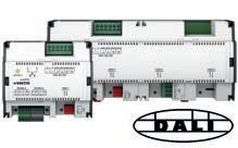
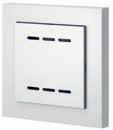
Intelligent lighting control is crucial for energy efficiency and comfort in buildings. The SAUTER ecos room automation system controls heating, ventilation, air conditioning, lighting and shading. It optimises the use of artificial light by utilising daylight and identifying unused rooms. It also prevents simultaneous cooling and heating. The extended DALI interface of the ecos504/505 stations now allows efficient, event-based integration of DALI-2 sensors and push-buttons and supports other DALI device types such as emergency or safety lights and DALI “Smart Data”.
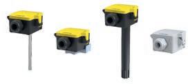
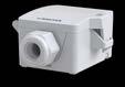
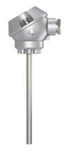
The SAUTER product range for data capture is specially designed for building automation and HVAC engineering. The EGT temperature and the EGH humidity sensors have been updated and are now available in a new housing design that is optimised for fast installation. In addition, a new 150 mm-long duct temperature sensor has been introduced to bridge the gap between the 100 mm and 200 mm duct sensors.
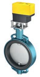
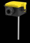
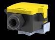
The ADM333 actuators are powerful and robust solutions for SAUTER butterfly valves. They offer high holding forces when de-energised and a constant positioning speed. With a conventional cut-off facility, they are easy to put into operation and are suitable for retrofitting in existing plants. The robust devices are designed for durability in harsh environments. Versatile fastening options and suitable mounting kits for SAUTER DEF valves complete the range.
The Customer Portal is an information platform with essential building information and contact data. It gives asset and service managers a consolidated overview of information such as room utilisation, energy consumption, CO2 emissions and system statuses, as well as operating costs and service information for their buildings and premises. The integrated communication area allows planning of maintenance schedules and storage of detailed information, reports and dates, as well as contract data and checklists with logs. These can be viewed using the timeline widget in the dashboard.

SAUTER CO2 sensors offer precise measurements, versatility, guaranteed long-term stability and fast response times.
EGQ 220 and 222 room transducers
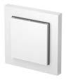
The range of room transducers for measuring temperature, humidity, VOCs and CO2 now have a new, timeless design.
viaSens FMS 116, 117, 196 and 197 smart sensors
The viaSens smart sensor measures VOC, temperature, humidity, brightness, presence and sound level, and now also CO2 (FMS 117 and 197). It also features an animated LED ring and communicates via Bluetooth and MQTT.

Remote Management enables digital services in building automation and energy management from a distance. Service staff, building operators and facility managers benefit from direct access to decentralised systems, which allows faster troubleshooting, more efficient maintenance and monitoring, as well as optimised operation. Secure access via the SAUTER Cloud takes place using a browser or VPN Windows client. The Remote Management Connector can also be used as a universal gateway, for which various protocols are available, including Modbus RTU/IP, M-Bus, BACnet/IP and MSTP, and IoT. It can also be used as a protocol extension for SAUTER Vision Center.


From installation to service. Mobile apps supplement the SAUTER product portfolio. They help users execute tasks or provide services remotely. Here is a handy overview of the apps that are currently available.
Overview of mobile apps (alphabetical order)
Name Main functions iOS Android
ecoUnit

eValveco Assistant
Mobile Room Control, the Mobile Building Services app
modulo 6
Smart Actuator

ValveDim
viaSens
• Controlling the ecoUnit Touch room operating unit (EY-RU365)
• Commissioning, configuration, service and operation
• Creating and managing projects
• Operating room functions, information and notifications for tenants, owners and operators
• Booking meeting rooms, assets, parking spaces and workspaces
• Commissioning, service and operation


• Commissioning, service and operation
• Application selection and configuration
• Creating and managing projects
• Access to the SAUTER valve and actuator portfolio
• Configuring valve and actuator combinations
• Commissioning the sensor in the SAUTER meshNet
• Sensor network configuration
• Basic configuration of the sensor
• Calibration of the sensor
• Beacon transmission capacity display


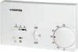
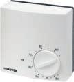
Two-point controllers from SAUTER are used to limit, regulate and monitor temperature, pressure and humidity, with no auxiliary energy required. They provide reliability, even in difficult conditions.
SAUTER fan-coil controllers are used for demand-led activation of fan-coil units and ensure that they are operated with optimum use of energy. There are controllers for fan-coil units with a three-speed fan and for continuous control of EC motors. The controllers are suitable for 2- and 4-pipe systems, as well as for fan-coil units with an electric reheater
Type designation
Indicating and operating elements
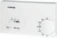
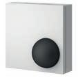
TSHK 621...643
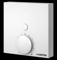
TSHK 670...672
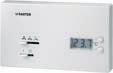
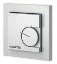
TSHK 681...682
Features
• Variable room temperature as setpoint based on printed temperature scale
• Changeover from heating to cooling via switch or type of connection
• ON/OFF toggle switch for mains voltage, plus other slide switches for operating mode and fan, depending on the type
• More constant room temperature due to thermal feedback
• Suitable for wall mounting or fitting on recessed junction boxes
• Setpoint adjuster with mechanical min. and max. limitation of the setting range
• 2-point pulsed activation
• Individual unitary temperature control in residential and business rooms for activating, for example, electric heating systems, thermal actuators, or fans or cooling units in air-conditioning systems.
Technical data
Power supply
Parameters
Ambient conditions
Outputs
Construction
Standards and directives
Power supply1)
230 V~, approx. ±10%, 50...60 Hz
Setting range 5...30 °C
Proportional band 3 K
Hysteresis2)
Shortest switching interval
Approx. ±0.1...0.5 K
Approx. 19 minutes (E = 0.5)
Time constant in still air 20 minutes
Dead time in still air 2 minutes
Time constant in moving air (0.2 m/s)15 minutes
Dead time in moving air (0.2 m/s)1 minute
Ambient temperature 0...55 °C
Load
Fan load
Weight
Housing
Housing material
6(3) A, 230 V~
6(3) A, 230 V~
0.18 kg
Pure white (RAL 9010)
Fire-retardant thermoplastic (fire classification UL94 HB)
Baseplate Black thermoplastic with bimetallic sensor and contact snap mechanism with permanent magnet
Cable inlet At rear
Screw terminals
Type of protection
For electrical cables of up to 2.5 mm²
IP30 (EN 60529)
Protection class II (IEC 60730)
Energy class I = 1%
as per EU 811/2013, 2010/30/EU, 2009/125/EC
1) 10% more voltage results in: Proportional band approx. 4 K, switching period 15 min, actual-value reduction approx. 0.5 K
2) Devices with thermal feedback are pulsed by a built-in heating resistor. The control factor reduces as the temperature increases (i.e. the controller has proportional behaviour). A small temperature variation of ±0.1...0.5 K occurs as a result of pulsing, depending on the time constant of the room
TSHK6**F00*

Overview of types
Type Operating mode
TSHK621F001Heating/cooling; 2-pipe
TSHK642F001Heating only / cooling only; 2-pipe
TSHK643F001Heating/cooling; 4-pipe
Mains switch on/off • • •
Operating mode switch ir ir
Fan speeds opü opü opü
Accessories
Type Description
0362239001Pure white intermediate cover plate, suitable for various recessed junction boxes
2-point controllers | Thermostats
Features
• Variable room temperature as setpoint based on printed temperature scale
• Gradual transition from heating to cooling through sequence characteristic
• Variants with master switch plus slide switch for the fan
• Suitable for wall mounting or fitting on recessed junction boxes
• Electronics unit and switching relay
• Setpoint adjuster with mechanical min. and max. limitation of the setting range
• Quasi-continuous temperature control
• 2-point pulsed activation
• Individual unitary temperature control in residential and business rooms for activating, for example, electric heating systems, thermal actuators, or fans or cooling units in air-conditioning systems.
Technical data
Power supply
Parameters
Ambient conditions
Outputs
Function
Construction
Power supply
230 V~, approx. ±10%, 50...60 Hz
Setting range 5...30 °C
Proportional band 2 × 3 K
Sequence dead zone
Hysteresis1)
2 K ±0,7
Approx. ±0.1...0.5 K
Shortest switching interval Approx. 19 minutes (E = 0.5)
Time constant in still air 20 minutes
Dead time in still air 2 minutes
Time constant in moving air (0.2 m/s)15 minutes
Dead time in moving air (0.2 m/s)1 minute
Ambient temperature 0...55 °C
Load
Fan load
Operating mode
Weight
Housing
Housing material
Baseplate
Standards and directives
TSHK67*F001
10(4) A, 230 V~
6(3) A, 230 V~
Heating/cooling sequence; 4-pipe
0.18 kg
Pure white (RAL 9010)
Fire-retardant thermoplastic (fire classification UL94 HB)
Black thermoplastic with NTC sensor
Cable inlet At rear
Screw terminals
Type of protection
For cables of up to 2.5 mm²
IP30 (EN 60529)
1) The device is pulsed electronically. When the temperature increases, the control factor is reduced to 0 on the “Heating” output and increased to E = 1 on the “Cooling” output. A small temperature variation of ±0.1...0.5 K occurs as a result of pulsing, depending on the time constant of the room

Overview of types
Type Number of switches
TSHK670F0010
TSHK672F0012
Protection class II (IEC 60730)
Energy class I = 1% as per EU 811/2013, 2010/30/EU, 2009/125/EC
Mains switch ON/OFF • Fan speeds o p ü
Indicators/display 1 LED
Accessories
Type Description
0362239001Pure white intermediate cover plate, suitable for various recessed junction boxes
2-point controllers | Thermostats
Features
• LCD of the room temperature or setpoint, with two buttons (±) for adjusting the setpoint
• Output for heating or cooling depending on connection type, or change in direction of operation with external switch
• With main switch for mains power supply and slide switch for three fan speeds
• Suitable for wall mounting or fitting on recessed junction boxes
• Electronics unit and switching relay
• Quasi-continuous temperature control
• 2-point pulsed activation
• Individual unitary temperature control in residential and business rooms for activating e.g. electric heating systems, thermal actuators, or fans or cooling units in air-conditioning systems.
Technical data
Power supply
Parameters
TSHK68*F001
Ambient conditions
Outputs
Construction
Standards and directives
Power supply1)
230 V~, approx. ±10 V, 50...60 Hz
Setting range 5...30 °C; resolution 0.5 °C
Proportional band 3 K
Display of actual value 0...40 °C; resolution 0.1 °C
Hysteresis2)
Shortest switching interval
Approx. ±0.1...0.5 K
Approx. 18 minutes (E = 0.5)
Time constant in still air 20 minutes
Dead time in still air 2 minutes
Time constant in moving air (0.2 m/s)15 minutes
Dead time in moving air (0.2 m/s)1 minutes
Ambient temperature 0...55 °C
Load
3(2) A, 230 V~ Fan load
Weight
Housing
6(3) A, 230 V~
0.18 kg
Pure white (RAL 9010)
Housing material Fire-retardant thermoplastic (fire classification UL94 HB)
Baseplate
Black thermoplastic with NTC sensor
Cable inlet At rear
Screw terminals
Type of protection
For cables of up to 2.5 mm²
IP30 (EN 60529)
Protection class II (IEC 60730)
Energy class I = 1% as per EU 811/2013, 2010/30/EU, 2009/125/EC
1) 10% more voltage results in: Proportional band approx. 4 K, switching period 15 min, actual-value reduction approx. 0.5 K
2) The device is pulsed electronically. When the temperature increases, the control factor falls to zero at the “Heating” output and rises to E = 1 at the “Cooling” output. A small temperature variation of ±0.1...0.5 K occurs as a result of pulsing, depending on the time constant of the room

2-point controllers | Thermostats
Overview of types
Type
Operating mode
TSHK681F001Heating or cooling or heating/cooling; 2-pipe
TSHK682F001Heating/cooling; 4-pipe
Mains switch ON/OFF • (•)
Operating mode switch i OFF r o
Fan speeds o p ü o p ü
Indicators/display °C digital °C digital
Accessories
Type Description
0362238001Cable temperature sensor, 4 m long, made of PVC, for external temperature measurement (max. 50 m)
0362239001Pure white intermediate cover plate, suitable for various recessed junction boxes
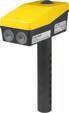
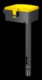
Temperature control, temperature monitoring and temperature limitation: SAUTER universal thermostats are used for these three applications. They provide control, monitoring and limitation according to needs without auxiliary energy
Clamp-on temperature
Operating mode
Temperature controller, monitor (TR, TW)
Safety temperature limiter (STB)
Temperature limiter (TB)
Further information Page 18
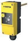
TUC*0*F00* TW, STW TB, STB
Features

TUC207F003 TUC407F001
TUC407F002
• Regulates and monitors the temperature of liquids in baths, containers, pipes, ducts and HVAC installations
• Variants as temperature monitor (TW) and temperature limiter (TB)
• Double thermostat as TW and TB
• Thermostat with remote sensor
• Clamp-on thermostat
• Capillary tube thermostat with or without thermowell
• The shift in the change-over point is minimised due to the temperature compensation
• Thermowell supplied (max. 12 bar)
The following features and certifications do not apply to the United Kingdom of Great Britain and Northern Ireland (UK):
• Variants as safety temperature monitor (STW), or safety temperature limiter (STB)
• Double thermostat as STW or STB
• As per PED 2014/68/EU classified as cat. IV (TUC207F003, TUC407F001, TUC407F002)
Use in safety applications is not permitted in the United Kingdom.
Technical data
Power supply
Max. load
Min. load
Parameters
Ambient conditions
Construction
Standards, directives
Terminal 1-2
Terminal 1-4
Adjustment point
Effect of temperature at instrument head
230 VAC, 10(2.5) A (on the normallyclosed contact)
230 VAC 2(0.4) A
Terminal 1-2, 1-4 24 VAC/DC, 100 mA
At ta 22 °C
Approx. –0.1...–0.2 K/K
Time constant with thermowell (LW 7)< 45 s (water) < 60 s (oil)
Time constant without thermowell< 120 s (air)
Ambient temperature
0...70 °C
Storage and transport temperature−25...80 °C
Max. pipe temperature during fitting120 °C
Connection terminals
Cross-section of cable
Protection class I (EN 60730) 2-point controllers
Plug-in connectors
0.75...2.5 mm2
Sensor cartridge Ø 6.5 mm
Housing
Housing material
Two sections, lower section black, upper section yellow, including inspection window
PA, ABS, PMMA
Weight 0.2 kg
Type of protection

IP54 (EN 60529)
2-point
Type
Approval
TUC101F003−10…50 °CTWApprox. 4.2 K 1.6 m80 mm100 mm, brass 140 °C CE, UKCA
TUC102F001 5...30 °CTWApprox. 5.6 K 0.7 m65 mm100 mm, brass 200 °CCE, UKCA
TUC105F001 15...95 °CTWApprox. 5.6 K 0.7 m65 mm100 mm, brass 200 °CCE, UKCA
TUC106F001 40...120 °CTWApprox. 5.6 K 0.7 m65 mm100 mm, brass 200 °CCE, UKCA
TUC107F001 50...130 °CTWApprox. 5.6 K 0.7 m65 mm100 mm, brass 200 °CCE, UKCA
TUC108F001 80...160 °CTWApprox. 5.6 K 0.7 m65 mm100 mm, stainless steel 200 °CCE, UKCA
TUC207F003 70...130 °CSTWApprox. 10 K 1.6 m60 mm100 mm, brass 160 °CCE
TUC303F001 15...60 °CTB≤ 20 K0.7 m70 mm100 mm, brass 200 °CCE, UKCA
TUC307F001 50...130 °CTB≤ 20 K0.7 m65 mm100 mm, brass 200 °CCE, UKCA
TUC407F001 95...130 °CSTB≤ 20 K0.7 m76 mm100 mm, brass 160 °CCE
TUC407F002 95...130 °CSTB≤ 20 K0.7 m76 mm150 mm, brass 160 °CCE
A Universal thermostats approved in the UK must not be used as STW or STB in safety applications.
A The TUC207F003, TUC407F001 and TUC407F002 devices comply with modules B (type test) and D (QA system, CE 0035) of Pressure Equipment Directive 2014/68/EU.
A Only use the supplied thermowells or stainless steel thermowells (part nos.: 0393022*** or 0392022***) with the TÜV-certified devices.
A TUC108F001 with adapter for temperature reduction, only mount with supplied thermowell.
Accessories
Type Description
0300360008Retaining holder for cable temperature sensor or capillary tube with 0392022*** (LW 7) or LW 15 (10 pcs)
0300360009Holder for sensor cartridge
0300360010Retaining strap for fitting onto pipes with a diameter of 15…100 mm
0300360011Mounting plate for double thermostats
0300360012Sensor support spiral for fitting in ventilation duct
0300360013Duct/wall mounting bracket
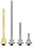
Features
• Fitted in pipes and containers for holding sensor cartridges, immersion stems, temperature sensors, temperature controllers or thermostats
• Made of brass (Ms) or stainless steel (V4A)
• Versions with cylindrical pipe thread (G½" male ISO 228/1, flat-sealing)1) or cone-shaped (R½" ISO 7/1 sealing in thread)
• With pressure spring (LW 15)
• With retaining holder

03910222007200
03910223007300
03910224507450
2-point controllers | Thermostats
A 0392022100 and 0392022300 for TUC thermostats only
A With the TUC407F001 and TUC207F003, only use the supplied thermowells or stainless-steel thermowells (part nos.: 0393022*** or 0392022***).
A 0391... with pressure screw (retaining holder) up to max. 200 °C
Accessories
Type Description
0300360008Retaining holder for cable temperature sensor or capillary tube with 0392022*** (LW 7) or LW 15 (10 pcs)
0364263000Welding sleeve of steel, with female thread G½", flat seal of copper
0300360017Pressure spring for LW 15 (10 pieces)
LW 7, 50 mm
LW 7, 100 mm
LW 7, 150 mm
LW 7, 200 mm
LW 7, 300 mm
LW 7, 450 mm
LW 7, 600 mm
LW 15, 100 mm
LW 15, 200 mm
LW 15, 450 mm
0392022100
0392022200
0392022300
A 0392022100 and 0392022300 for TUC thermostats only.
50 mm
300 mm
A With the TUC407F001 and TUC207F003, only use the supplied thermowells or stainless-steel thermowells (part nos.: 0393022*** or 0392022***).
A Only use the thermowells (LW 15) with at least 2 sensors or thermostats with a diameter of at least 6 mm
A 0391... with pressure screw (retaining holder) up to max. 200 °C.
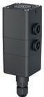
SAUTER frost monitors protect ventilation systems against icing. With their special construction and design, they are particularly suitable for compact installations and/or installations that are subject to vibrations.
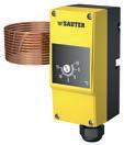
2-point controllers | Frost monitors
Features
• Temperature monitoring in heating coils and air ducts
• Variants as monitors or limiters
• Copper capillary tube
• Switching point can be set internally
• Small switching difference
• With capillary-tube holders made of plastic
Technical data
Power supply
Max. load
Parameters
Time characteristic
Ambient conditions
Construction
Standards, directives
Overview of types
Terminal 1-2
Terminal 1-4
230 VAC, 10(2.5) A (on the normallyclosed contact)
230 VAC 2(0.4) A
Setting range −10...15 °C
Factory setting 5 °C
Switching difference 1.5 K
Tolerance of switching differenceMax. ±1 K
Max. sensor temperature 120 °C
Time constant in moving air (0.3 m/s)1) Capillary tube length 1.5 m: 25 s
Capillary tube length 3 m: 31 s
Capillary tube length 6 m: 51 s
Ambient temperature2) −5...70 °C
Max. capillary temperature120 °C
Storage and transport temperature−30...80 °C
Connection terminals
Plug-in connectors
Cross-section of cable Ø 0.75...2.5 mm2
Housing
Two sections, lower section black, upper section yellow, including inspection window
Housing material ABS, PMMA Weight 0.2 kg
Type of protection
IP65 (EN 60529)
Protection class I (IEC 60730)
EMC Directive 2014/30/EUEN 60730-1, EN 60730-2-9
Low-Voltage Directive 2014/35/EUEN 60730-1, EN 60730-2-9
1) The frost monitor always reacts to the coldest point (minimum length
2) The head of the instrument must be fitted in a warmer location than the sensor; see fitting instructions
(6 m))

2-point controllers | Frost monitors
Accessories
Type Description
0300360014Six holders for fitting the capillary tube
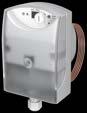
Features
• Records the lowest temperature that occurs for a length of at least 250 mm at any position along the capillary tube
• Used on air side in ventilation and air conditioning units where protective measures must be taken against freezing
• Active capillary sensor for measuring the lowest temperatures in the range 0...15 °C
• Vapour-filled capillary tube and diaphragm system with inductive system of measurement
• Setting range 1...10 °C
• Start-up function
• LED and 7-segment display
• Self-monitoring of sensor line
Technical data
Power supply
Power supply1)
Parameters
Inputs/outputs
Analogue input
Analogue outputs
Potential-free relay outputs (Q terminals)
Ambient conditions
Operation
Storage and transport
Construction
24 V~, 10/-20%
Power consumption < 6.6 VA
Frequency 50...60 Hz
Measuring range 0...15 °C
Setting range 1...10 °C
Adjustment point 5 °C
Accuracy for adjustment point± 1 K
Switching difference Approx. 2 K
Temperature for capillary tube< 110 °C
Time constant in still air
Approx. 90 s
Time constant in moving air< 40 s
Response length for capillary tubeMin. 250 mm
Admissible cable length 300 m with 1.5 mm²
Valve control for terminal Y0...10 V
Current < 0.1 mA
Sensor temperature for terminal B0...10 V ≙ 0...15 °C
Valve control for terminal Y100...10 V
Current ±1 mA
Min. switching capacity 12 V~/=, 100 mA
Max. switching capacity 250 V~, 6(2) A; 24 V=, 6 A
Humidity (non-condensing)< 85% rh
Temperature -15...55 °C
Humidity (non-condensing)< 95% rh
Temperature -25...65 °C
Terminals with spring technologyMax. 2 × 1.5 mm² Or 1 × 2.5 mm²
Cable inlet
Protection class2) I
Min. 0.25 mm²
Cable gland M16 for cable diameter 5...10 mm
Housing PA, silver grey (RAL 7001)
1) SELV/PELV: Safety Extra Low Voltage/Protected Extra Low Voltage
2) No earth conductor necessary

2-point controllers
Standards and directives
Housing cover PC, transparent
Cap ABS, light grey (RAL 7035)
Capillary tube Copper
Vibration resistance EN 60721-3-3 (class 3M2)
Type of protection IP42 (EN 60529)
Operation as per IEC 721-3-3Class 3K5
Storage and transport as per IEC 721-3-2 Class 2K3
RoHS Directive 2011/65/EUEN IEC 63000
EMC Directive 2014/30/EUEN 61000-6-1, EN 61000-6-2, EN 61000-6-3
Low-Voltage Directive 2014/35/EUEN 60730-1, EN60730-2-9
Overview of types
TFL611F201Continuous
TFL611F601
Accessories
Type Description
0292146001Set for duct fitting consisting of: 5 capillary-tube holders, 1 depth-adjustable flange 0300360014Six holders for fitting the capillary tube 0374534001Depth-adjustable flange
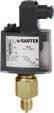
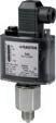
SAUTER pressure switches can be used in any application for controlling and monitoring the pressure in liquids, gases and vapours. They detect changes in pressure in gaseous and/or liquid media and are used to switch pumps, valves or compressors.
Type
Pressure limiters
Differential pressure switch
Pressure sensors
Of brass
Of stainless steel
Switching difference
Lloyds Register
Can be used for aggressive
Features
• For regulating and monitoring pressure in liquids, gases and vapours
• Especially suitable for applications in compact installations
• Upper switching point can be adjusted
• Fixed switching difference, no hysteresis setting is necessary
• Sealable
• Pressure sensor made of brass for non-aggressive media
Technical data
Power supply
Parameters
Ambient conditions
Construction
Maximum load with gold-plated contacts1)
400 mA, 24 V, 10 VA
Minimum load with gold-plated contacts 4 mA, 5 V
Maximum load with silver-plated contacts 10(4) A, 250 VAC, 50 W, 250 VDC
Minimum load with silver-plated contacts 100 mA, 24 V
Pressure connection G½" A
Admissible sensor temperature70 °C
Ambient temperature −20...70 °C
Fitting
Housing
Housing material
Device plug
Standards, directives
Pipe and wall mounting
Transparent cover
Impact-proof thermoplastic
Standard female connector for Ø 6...10 mm cable
Type of protection2) IP65 (EN 60529)
Protection class I (IEC 60730)
CE/UKCA conformity3) LVD 2014/35/EU (CE) EN 60730-1, EN 60730-2-6
EESR-2016 (UKCA) EN 60730-1, EN 60730-2-6
EMC-D 2014/30/EU (CE)EN 61000-6-1, EN 61000-6-2 EN 61000-6-3, EN 61000-6-4
EMC-2016 (UKCA) EN 61000-6-1, EN 61000-6-2 EN 61000-6-3, EN 61000-6-4
Machinery-D 2006/42/EC (CE)EN ISO12100: Annex II B of the Reg. SMSR-2008 (UKCA) EN ISO12100: Annex II B of the Reg. (Partly Completed Machinery)
RoHS-D 2011/65/EU & 2015/863/EU (CE)
RoHS-2012 (UKCA)
PED 2014/68/EU (CE)

EN IEC 63000
EN IEC 63000
Article 4.3 and Annex A of the Reg. PESR-2016 (UKCA)
Article 8.3 and Essential Safety Requirements of the Reg.
1) If the contacts are subjected to a load greater than specified, the gold plating will be destroyed. They are then classed merely as silver contacts and lose the properties of gold-plated contacts.
2) Depending on the fitting position, see the fitting instructions. The devices are not suitable for outdoor applications.
3) Use as a pressure limiter is not permitted. The use of an electrical interlock is not permitted.
Overview of types
Type Setting rangeSwitching
DSA140F0020.5...2.5 bar0.25 bar12 bar-0.7 bar0.5 kg
DSA143F0020.5...6 bar0.3 bar16 bar-0.7 bar0.5 kg
DSA146F0021...10 bar0.4 bar20 bar-1.0 bar0.4 kg
A DSA: Pressure sensor made of brass for non-aggressive media; Xs = upper switching point
Accessories
Type Description
0035465000Throttle screw for absorbing pressure surges, brass
0214120000Throttle screw for absorbing pressure surges, stainless steel
0292001000Setpoint adjuster according to customer's wishes (setting accuracy: ±3% of the setting range, but a minimum of ±0.2 bar)
0292004000Setpoint adjuster sealed (with accessory 0292001000 only)
0292018001Damping screw for absorbing pressure surges in low viscosity media
0292150001Fixing bracket for wall mounting
0296936000Fixing brackets for rail: top-hat rail EN 60715, 35 × 7.5 mm and 35 × 15 mm
0300360007Capillary throttle, stainless steel, length 1 m, G½"-G½"
0311572000Screw fitting for copper tubes of Ø 6 mm, brass
0381141001Profile sealing ring, copper, for G½"
A 0296936000: With accessory 0292150001 only
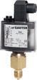
Features
• For regulating and monitoring pressure in liquids, gases and vapours
• Adjustable lower switching point
• Adjustable switching difference
• Sealable
• Pressure sensor made of brass for non-aggressive media (DSB)
• Pressure sensor made of stainless steel for aggressive media (DSF)
• SIL 2-certified as per IEC 615081)
• Approved for marine applications (GL- and LR-certified)
Technical data
Power supply
Maximum load with gold-plated contacts2)
400 mA, 24 V, 10 VA
Minimum load with gold-plated contacts 4 mA, 5 V
Maximum load with silver-plated contacts 10(4) A, 250 VAC, 50 W, 250 VDC
Minimum load with silver-plated contacts 100 mA, 24 V
Parameters
Ambient conditions
Construction
Standards, directives


CE/UKCA conformity5)
Pressure connection G ½" A
Ambient temperature −20…70 °C
Housing
Housing material
Device plug
Type of protection3)
Transparent cover
Impact-proof thermoplastic
Standard female connector for cable Ø 6…10 mm
IP65 (EN 60529)
Protection class I (IEC 60730)
Test mark4) TÜV
DWFS (SDBFS) ID: 06024
Ship-approved Germanischer Lloyd (GL) Lloyds Register (LR)
LVD 2014/35/EU (CE) EN 60730-1, EN 60730-2-6
EESR-2016 (UKCA) EN 60730-1, EN 60730-2-6
EMC-D 2014/30/EU (CE)EN 61000-6-1, EN 61000-6-2, EN 61000-6-3, EN 61000-6-4
EMC-2016 (UKCA) EN 61000-6-1, EN 61000-6-2, EN 61000-6-3, EN 61000-6-4
Machinery-D 2006/42/EC (CE)EN ISO12100:2018
1) SIL 2 approval is not valid in the United Kingdom (UK).
2) If the contacts are subjected to a load greater than specified, the gold plating will be destroyed. They are then classed merely as silver contacts and lose the properties of gold-plated contacts
3) Depending on the fitting position, see the fitting instructions. The devices are not suitable for outdoor applications.
4) For the EU: DWFS (SDBFS): As a safety pressure limiter when an external electrical locking facility is fitted downstream in the circuit. Certificates can be downloaded from www.certipedia.com.
For the United Kingdom (UK): Use as a safety pressure limiter is not permitted. The use of an electrical interlock is not permitted.
5) Explanation of abbreviations in the “Further information” section of the product data sheet and in the appendix to SAUTER’s product catalogues
SMSR-2008 (UKCA)
RoHS-D 2011/65/EU & 2015/863/EU (CE)
RoHS-2012 (UKCA)
EN ISO12100:2018
EN IEC 63000:2018
EN IEC 63000:2018 PED 2014/68/EU (CE)
VdTÜV pressure information sheet 100, sheet 1, cat. IV EN 12952-11, EN 12953-9
PESR-2016 (UKCA)6)
Article 8.3 of the Reg. AD 2000 Rulebook SIL conformity as per SIL 2 Standards7) IEC 61508 parts 1-2 and 4-7
Overview of types
Type
DSB138F0010...1.6 bar0.25...0.65 ba r 12 bar70 °C-0.7
DSB140F0010...2.5 bar0.25...0.75 ba r 12 bar70 °C-0.7
DSB143F0010...6 bar0.3...1.6 bar16 bar70 °C-0.7 bar0.5 kg
DSB146F0010...10 bar0.8...3.7 bar30 bar70 °C-1 bar0.4 kg
DSB152F0016...16 bar1...4 bar30 bar70 °C-1 bar0.4 kg
DSB158F0010...25 bar1...7.5 bar60 bar70 °C-1 bar0.4 kg
DSB170F0015...40 bar1.4...7.5 bar60 bar70 °C-1 bar0.4 kg
DSF125F001–1...1.5 bar0.25...0.75 ba r 12 bar110 °C-1 bar0.5 kg
DSF127F001–1...5 bar0.3...1.5 bar16 bar110 °C-1 bar0.5 kg
DSF135F0010...0.6 bar0.12...0.60 ba r 12 bar110 °C-1 bar0.5 kg
DSF138F0010...1.6 bar0.25...0.7 bar12 bar110 °C-1 bar0.5 kg
DSF140F0010...2.5 bar0.25...0.75 ba r 12 bar110 °C-1 bar0.5 kg
DSF143F0010...6 bar0.3...1.5 bar16 bar110 °C-1 bar0.5 kg
DSF146F0010...10 bar0.8...3.0 bar18 bar110 °C-1 bar0.5 kg
DSF152F0010...16 bar1.2...3.8 bar60 bar110 °C-1 bar0.3 kg
DSF158F0010...25 bar1.5...8.0 bar60 bar110 °C-1 bar0.3 kg
DSF170F00115...40 bar1.7...8.2 bar60 bar110 °C-1 bar0.3 kg
A DSB: Pressure sensor made of brass for non-aggressive media; XS = lower switching point.
A DSF: Pressure sensor made of stainless steel for aggressive media; XS = lower switching point.
A The switching difference must be within the setting range of the switching point. The minimum values of the switching difference are only possible in the lower setting range.
Accessories
Type Description
0292001000Setpoint adjuster according to customer's wishes (setting accuracy: ±3% of the setting range, but a minimum of ±0.2 bar)
0292002000Switching difference according to customers' wishes (setting accuracy: ±5% of the setting range, but a minimum of ±0.05 bar, with accessory 0292001000 only)
0292004000Setpoint adjuster sealed (with accessory 0292001000 only)
0292150001Fixing bracket for wall mounting
0296936000Fixing brackets for rail: top-hat rail EN 60715, 35 × 7.5 mm and 35 × 15 mm
0311572000Screw fitting for copper tubes of Ø 6 mm, brass
0381141001Profile sealing ring, copper, for G½"
A 0296936000: With accessory 0292150001 only
6) SIL 2 approval is not valid in the United Kingdom (UK).
7) SIL 2 approval is not valid in the United Kingdom (UK).
Features
• Switching point can be adjusted
• Sealable
• Pressure sensor made of brass for non-aggressive media (DSL)
• Pressure sensor made of stainless steel for aggressive media (DSH)
• Locking type: With falling pressure (DSL) or with rising pressure (DSH)
• SIL 2 certified as per IEC 61508
• Approved for marine applications (GL and LR certified)
Technical data
Power supply
Parameters
Ambient conditions
Construction

Standards and directives
Maximum load with gold-plated contacts1) 400 mA, 24 V, 10 VA
Minimum load with gold-plated contacts 4 mA, 5 V
Maximum load with silver-plated contacts 10(4) A, 250 VAC, 50 W, 250 VDC
Minimum load with silver-plated contacts 100 mA, 24 V
Pressure connection G ½" A
Ambient temperature
Housing
Housing material
Device plug
Type of protection2)
−20…70 °C
Transparent cover
Impact-proof thermoplastic
Standard female connector for cable of Ø 6…10 mm
IP65 (EN 60529)
Protection class I (IEC 60730)
Test mark3)
TÜV
DSL: SDBF ID: 06022
DSH: SDB ID: 06023
PED: 2014/68/EU, cat. IV
Ship-approved Germanischer Lloyd (GL) Lloyds Register (LR)
CE conformity according toEMC Directive 2014/30/EUEN 61000-6-1, EN 61000-6-2, EN 61000-6-3, EN 61000-6-4
Low-Voltage Directive 2014/35/EUEN 60730-1, EN 60730-2-6 PED 2014/68/EU
VdTÜV pressure information sheet 100, cat. IV
EN 12952-11, EN 12953-9
Machinery Directive 2006/42/EC (according to Appendix II, 1B)
SIL conformity as per SIL 2 Standards

EN ISO 12100:2018
IEC 61508 parts 1-2 and 4-7
1) If the contacts are subjected to a load greater than specified, the gold plating will be destroyed. They are then classed merely as silver contacts and lose the properties of gold-plated contacts
2) Depending on the fitting position, see the fitting instructions. The devices are not suitable for outdoor applications.
3) Certificates can be downloaded from www.certipedia.com. The certificates are not valid in the United Kingdom of Great Britain and Northern Ireland.
Overview of types
/ Min. change for reset: Average values
Type Setting rangeMin. change for reset Maximum pressure Admissible sensor temperature Admissible vacuum loading Weight
DSL140F0010...2.5 bar0.4 bar12 bar70 °C-0.7 bar0.5 kg
DSL143F0010...6 bar0.5 bar16 bar70 °C-0.7 bar0.5 kg
DSL152F0016...16 bar1.2 bar30 bar70 °C-1.0 bar0.4 kg
DSH127F001-1...5 bar-0.4 bar16 bar110 °C-1.0 bar0.5 kg
DSH143F0010.5...6 bar-0.45 bar16 bar110 °C-0.7 bar0.5 kg
DSH146F0011...10 bar-0.8 bar18 bar110 °C-1.0 bar0.5 kg
DSH152F0012...16 bar-1.5 bar60 bar110 °C-1.0 bar0.3 kg
DSH158F0015...25 bar-1.8 bar60 bar110 °C-1.0 bar0.3 kg
DSH170F00115...40 bar-2.0 bar60 bar110 °C-1.0 bar0.3 kg
A DSL: Locks when the pressure falls (SDBF); pressure sensor made of brass for non-aggressive media. A DSH: Locks when the pressure rises (SDB); pressure sensor made of stainless steel.
Accessories
Type Description
0292001000Setpoint adjuster according to customer's wishes (setting accuracy: ±3% of the setting range, but a minimum of ±0.2 bar)
0292004000Setpoint adjuster sealed (with accessory 0292001000 only)
0292150001Fixing bracket for wall mounting
0296936000Fixing brackets for rail: top-hat rail EN 60715, 35 × 7.5 mm and 35 × 15 mm
0311572000Screw fitting for copper tubes of Ø 6 mm, brass
0381141001Profile sealing ring, copper, for G½"
A 0296936000: With accessory 0292150001 only
Features
• For regulating and monitoring pressure in liquids, gases and vapours
• Especially suitable for installations subject to vibrations
• Contact rating 1 mA/6 V to 10 A/400 V
• Gold-plated silver contacts, vibration-proof snap-action switch with single-pole change-over switch
• Upper and lower switching points can be set independently of each other
• Sealable
• Splashproof
• DFC17B**F001: Pressure sensor made of brass for non-aggressive media
• DFC27B**F002: Pressure sensor made of stainless steel for aggressive media
Technical data
Power supply
4) Explanation of abbreviations in the “Further information” section of the product data sheet and in the appendix to SAUTER’s product catalogues 2-point
Ambient conditions
Construction
Standards, directives
Maximum load with gold-plated contacts1)
200 mA, 50 V
Minimum load with gold-plated contacts 1 mA, 6 V
Maximum load with silver-plated contacts2)
10(2) A, 400 VAC (25 W), 250 VDC
Minimum load with silver-plated contacts 100 mA, 24 V
Media temperature
≤ 110 °C
Ambient temperature −40...70 °C
Housing
Housing material
Cable inlet
Screw terminals
Pressure connection
Type of protection
Transparent cover
Light alloy
PG 13.5
For electrical cables up to 2.5 mm²
G½" A
IP44 (EN 60529)
Protection class I (IEC 60730)
Test mark3)
Mode of operation
CE/UKCA conformity4)
TÜV
DWFS (SDBF) ID: 06018
DWFS (SDB) ID: 06019
DB (SDBF) ID: 06017
Type 2 B (EN 60730)
LVD 2014/35/EU (CE) EN 60730-1, EN 60730-2-6
EESR-2016 (UKCA) EN 60730-1, EN 60730-2-6
EMC-D 2014/30/EU (CE)EN 61000-6-1, EN 61000-6-2
EN 61000-6-3, EN 61000-6-4
EMC-2016 (UKCA) EN 61000-6-1, EN 61000-6-2
EN 61000-6-3, EN 61000-6-4
Machinery-D 2006/42/EC (CE)EN ISO12100:2018
1) If the contacts are subjected to a load greater than 200 mA, 50 V, the gold plating will be destroyed. They are then classed merely as silver contacts and lose the properties of gold-plated contacts
2) Take the RC circuitry into account for inductive loads
230/400 V networks
From 70 °C media temperature, the current must be reduced to 6 A
3) Certificates can be downloaded from www.certipedia.com. The certificates are not valid in the United Kingdom (UK).

SMSR-2008 (UKCA)
RoHS-D 2011/65/EU & 2015/863/EU (CE)
RoHS-2012 (UKCA)
EN ISO12100:2018
EN IEC 63000:2018
EN IEC 63000:2018 PED 2014/68/EU (CE)
VdTÜV pressure information sheet 100, sheet 1, cat. IV EN 12952-11, EN 12953-9 PESR-2016 (UKCA)5)
Article 8.3 of the Reg. AD 2000 Rulebook
A The switching difference must be within the setting range of the switching point. The minimum values of the switching difference are only possible in the lower setting range.
Accessories
Type Description
0311572000Screw fitting for copper tubes of Ø 6 mm, brass 0035465000Throttle screw for absorbing pressure surges, brass 0214120000Throttle screw for absorbing pressure surges, stainless steel 0300360007Capillary throttle, stainless steel, length 1 m, G½"-G½" 0292018001Damping screw for absorbing pressure surges in low viscosity media 0259189000Holder for raised wall mounting 0292019001Setpoint adjustment for each switching point according to customer's wishes (setting accuracy: ±3% of the setting range)
0292019002Sealing of the adjustment screw for each switching point (only with accessory 0292019001) 0381141001Profile sealing ring, copper, for G½"
5) For the United Kingdom (UK): Use as a safety pressure limiter is not permitted. The use of an electrical interlock is not permitted.
Features
• For monitoring the differential pressure in liquids, gases and vapours
• For use in, for example, filter technology and in process plants
• Differential pressure setting ranges from 0.06 to 6 bar
• Up to 80 °C media temperature
• High repeatability
• High overload protection
• Can be used in all neutral media, such as heating water, neutral gases, oils etc.
• Long serviceable life
• With fitting bracket
Technical data
Parameters
Ambient conditions
Construction
Standards, directives
Min. load
AC min: 0.1 A, 250 VAC, 25 VA
DC min: 0.1 A, 30 VDC
Max. load AC max: 3(1) A, 250 VAC, 250 VA DC max: 0.4 A, 30 VDC, 10 W
Temperature dependence 1.5%/10 K
Accuracy 3% of the setting range
Hysteresis 12% of the setting range
Mechanical serviceable life 106 switchings
Max. static operating pressure (positive and negative pressure) 16 bar
Ambient temperature −10…70 °C
Media temperature 0...80 °C (non-freezing media)
Ambient humidity 45…75% rh
Power cable1) 3...0.5 mm2
Diaphragms Chromium-nickel steel 1.4310
Connection thread G ⅛" (female thread)
Weight 0.2 kg
Type of protection
IP65 (EN 60529)
Protection class II (EN 60730)
CE conformity according toLow-Voltage Directive 2014/35/EUEN 60730-1, EN 60730-2-6
Altitude up to 2000 m
EMC Directive 2014/30/EUEN 55014-1
Click rate N < 0.2 Art. 4.4
PED 2014/68/EU Art. 4.3 and Art. 13, fluid group 2
Overview of types
Type Setting range (bar) DSD134F1020.06...0.6 DSD137F0020.10...1.0 DSD140F0020.25...2.5 DSD143F0020.6...6.0

Accessories
Type Description
0300360005Cutting ring fitting G⅛" to 6 mm pipe (2 pcs)
0300360006Pneumatic fitting G⅛" to 6 mm hose (2 pcs)
0300360016Throttle screws G⅛", G⅛" (2 pcs) 2-point controllers | Pressure
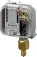
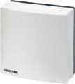
Room-, panel- and duct-mounted humidistats are used for monitoring and controlling humidity regulation devices (fans, driers and humidifiers).
Overview of humidistats
Features
• Monitoring and regulation of relative air humidity in rooms by controlling fans, drying units and air humidifiers
• Variable relative humidity as setpoint based on printed scale in % rh
• Measurement taken via a measuring element of stabilised synthetic textile tape
• Micro-switch with single-pole changeover contact
Technical data
Power supply
Parameters
Max. load
Min. load
Setting range
Setting accuracy1)
5(3) A, 250 VAC
100 mA, 24 VAC/DC
30...90% rh, no condensation
± 5% rh
Humidity calibration at 55% rh, 23 °C
Switching difference Xsd2)
Switching tolerance
Long-term stability
Typ. 8% rh (approx. 3% rh at calibration point)
Max. 3% rh
Approx. -1.5% rh/a
Time constant in moving air (0.2 m/s)Approx. 5 minutes
Effect of temperature
0.5% rh/K
Switching cycles > 100 000
Ambient conditions
Operation Temperature 0…50 °C
Storage and transport
Construction
Standards, directives
Ambient humidity 10...95% rh non-condensing Temperature -25...70 °C, no condensation
Dimensions W × H × D
Weight
Housing
Housing material
Connection terminals
Type of protection
76 × 76 × 34 × mm
0.1 kg
Pure white (RAL 9010)
Plastic, flame retardant, UL94 V0, UV stabilised
Screw terminals, for wire or braid, 0.5…1.5 mm² (AWG 21…16)
IP 30 (EN 60730-1), operating status
Protection class II (EN 60730)
Environment class 3K3 (IEC 60721-3-3)
CE conformity according toEMC Directive 2014/30/EUEN 60730-1
Low-Voltage Directive 2014/35/EUEN 60730-1, EN 60730-2-11
RoHS-D 2011/65/EU & 2015/863/EU EN IEC 63000
1) The setting accuracy of the humidistat is valid for the calibration point ±5% rh at 55% rh and 23 °C following initial calibration at the factory. See diagram «Setting accuracy». In general, humidity sensors (humidistats) are subject to increased ageing if they are used and/or stored in very contaminated air or corrosive gases. The humidistat may start to drift prematurely and its linearity may change under these conditions. If used in very contaminated air, the warranty does not cover a premature re-calibration or the replacement of the complete humidistat.
2) The switching difference depends on the ambient temperature. 2-point controllers

2-point controllers | Humidistats
Overview of types
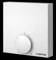
Type Features
HSC120F002Room-mounted humidistat with external setpoint adjuster
HSC120F012Room-mounted humidistat with internal setpoint adjuster
Features
• Monitoring and regulation of relative humidity by controlling fans, drying units and air humidifiers
• Adjustment of change-over point via setpoint adjustment axis
• Suitable for fitted applications with protection class II
• Measurement via a measuring element of stabilised synthetic textile tape
• Secured with bolting hole and fixing hole (blind hole)
• Micro-switch with single-pole change-over contacts and fixed switching difference
• Suitable for panel-mounted units only
Technical data
Power supply
Parameters
Ambient conditions
Max. load 5(3) A, 250 VAC Min. load 100 mA, 24 V
Setting range 25...95% rh
Setting accuracy1) ±5% rh
Humidity calibration at 55% rh, 23 °C
Switching difference Xsd2) Typ. 8% rh
Long-term stability –1.5% rh/a
Time constant in moving air (0.2 m/s)Approx. 3 minutes
Effect of temperature 0.5% rh/K
Operation Humidity (non-condensing)25...95% rh
Storage and transport
Construction
Standards, directives3)
Weight
(non-condensing)10...95% rh
0.03 kg
Baseplate Thermoplastic
Electrical connection AMP terminals 2.8 mm
Type of protection
IP00 (EN 60529)
Protection class 0 (IEC 60730)
CE conformity according toEMC Directive 2014/30/EUEN 55014 Art. 4.2
Low-Voltage Directive 2014/35/EUEN 60730-1, EN 60730-2-13
Overview of types
Type Features
HSC101F001Panel-mounted humidistat
1) The setting accuracy of the humidistat is valid for the calibration point ±5% rh at 55% rh and 23 °C following initial calibration at the factory. See diagram “Setting accuracy”. In general, humidity sensors (humidistats) are subject to increased ageing if they are used and/or stored in very contaminated air or aggressive gases. The humidistat may start to drift and its linearity may change under these conditions. If the humidistats are used in very contaminated air, the warranty does not cover a premature re-calibration or the replacement of the complete humidistat
2) Can be substantially improved by recalibration during usage
3) The fitting method must adhere to the relevant safety standards

Features
• Monitoring and regulation of relative humidity by controlling fans, drying units and air humidifiers
• Temperature-compensated humidity sensor
• Variable relative humidity as setpoint based on printed scale in % rh
• Includes fixing bracket with seal for duct or wall mounting
• For fitting in a ventilation duct or on a wall
• With single-pole change-over contacts and fixed switching difference Xsd
• Immersion depth 130...156 mm; includes fixing bracket
Technical data
Power supply
Parameters
Ambient conditions
Operation
Storage and transport
Construction
Standards and directives
Max. load
5(3) A, 250 VAC
Min. load 100 mA, 24 V
Setting range 15...95% rh
Setting accuracy ±5% rh
Humidity calibration at 55% rh, 23 °C
Temperature influence Compensated
Long-term stability –1.5% rh/a
Time constant in moving air (0.2 m/s)Approx. 3 minutes
Switching difference Xsd Typically 8% rh (after humidity calibration)
Max. air speed 10 m/s
Humidity (non-condensing)30...90% rh
Temperature 0...70 °C
Humidity (non-condensing)10...95% rh
Temperature -20...70 °C
Housing material
Glass-fibre-reinforced thermoplastic
Housing cover Thermoplastic, sealable
Sensor tube
Glass-fibre-reinforced thermoplastic, Ø 30 mm
Cable inlet PG 11
Screw terminals For electrical cables of up to 1.5 mm²
Type of protection IP30 (EN 60529)
Protection class II (IEC 60730)
EMC Directive 2014/30/EUEN 61000-6-1, EN 61000-6-2, EN 61000-6-3, EN 61000-6-4
Low-Voltage Directive 2014/35/EUEN 60730-1, EN 60730-2-13
Overview
For

2-point controllers | Humidistats
Accessories
Type Description
0303538001Set for increasing protection rating to IP55 (housing lid with transparent cap for setpoint knob, seal, 1 cable gland - PG 11, 1 plug - PG 11)
0370560011Cable screw fitting PG 11, plastic, for cable of Ø 9...11 mm
Accurate measured values are the basis for efficient control.
The results from the data capture form the basis for control and monitoring. SAUTER provides quality sensors for all physical variables, such as temperature, humidity, pressure, flow and air quality, that are specifically geared towards building automation systems and the HVAC industry.
Temperature
EGT 130, 330, 332, 335, 430: Room temperature sensor, surface-mounted
EGT 386, 388, 486, 686, 688: Room temperature sensors, recessed49
EGT 301: Outdoor-temperature sensor
EGT 353...356, 456, 554, 654: Cable temperature sensors
EGT 346…348, 392, 446, 447: Duct
SAUTER temperature sensors are used for heating and air-conditioning systems in residential, office and business spaces. They are used to measure room, duct, exterior and pipe temperatures.


EGT 130, 330, 332, 335, 430: Room temperature sensor, surface-mounted
Features
• Passive or active measuring element for room temperature
• Variants with setpoint adjuster, presence button and multicolour status LED
• Suitable for direct wall mounting and recessed junction boxes
Technical data
Ambient conditions
Construction
Standards, directives
CE/UKCA conformity1)
Ambient temperature
Ambient humidity
Colour
Housing material
Cable inlet
Connection terminals
Weight
Type of protection
−35…70 °C
Max. 85% rh, non-condensing
Traffic white (RAL9016)
Polycarbonate (PC) UL94-V0
Through the back
Spring-type terminals, max. 1.5 mm²
50 g
IP20 (EN 60529) after fitting
EMC-D 2014/30/EU (CE)EGT130F032: EN 60730-1 (mode of operation 1, residential premises)
EMC-2016 (UKCA)
RoHS-D 2011/65/EU & 2015/863/EU (CE)
RoHS-2012 (UKCA)
See EMC Directive
EN IEC 63000
EN IEC 63000
Resistance values
Measuring
A The tolerances only apply to the measuring elements. The accuracy of the sensor depends on the measuring element used and the cable length
EGT130F0320…50 °C Other ranges can be parametrised Typically ±1% of measuring range2)3) 0...10 V, min. load impedance 5 kΩ 15…24 VDC (±10%) / 24 VAC (±10%)
Max. 0.3 W (24 VDC) 0.5 VA (24 VAC)
Overview of types
Type Description Output signalMeasuring rangeSetpoint adjuster
EGT330F053Room temperature sensor Passive, Ni500−35…70 °C−
EGT330F103Room temperature sensor Passive, Ni1000−35…70 °C−
EGT332F103Room temperature sensor, setpoint adjuster Passive, Ni1000−35…70 °CPot. 2.5 kΩ
1) Explanation of abbreviations in the “Additional technical information” section of the product data sheet and in the appendix to SAUTER product catalogues
2) With offset adjustment ±3 K
3) The transducers must be operated at a constant operating voltage (±0.2 V). Current/voltage peaks when switching the supply voltage on/off must be prevented by the customer.

Data capture | Temperature
Type Description
Output signalMeasuring rangeSetpoint adjuster
EGT335F103Room temperature sensor, setpoint adjuster, presence button, status LED (RGB) Passive, Ni1000−35…70 °CPot. 2.5 kΩ
EGT430F013Room temperature sensor Passive, Pt100−35…70 °C−
EGT430F103Room temperature sensor Passive, Pt1000−35…70 °C−
EGT130F032Room temperature transducerActive, 0…10 V0…50 °C−
Accessories
Type Description 0300230010 USB Bluetooth® dongle
EGT 386, 388, 486, 686, 688: Room temperature sensor, recessed
Features
• Passive room temperature measurement
• For temperature measurement in dry rooms (e.g. in residential properties, offices and business premises)
• Including frame
Technical data
Parameters
Time characteristic
Ambient conditions
Construction
Measuring range -35...70 °C
Time constant in still air 30 minutes
Storage and transport temperature–35...70 °C
Ambient temperature -35...70 °C
Housing
Housing material
Standards, directives
Pure white
Thermoplastic
Frame design Gira E2
Type of protection
IP20 (EN 60529)
CE conformity according toRoHS Directive 2011/65/EUEN IEC 63000
Resistance values / characteristics
/ The tolerance listed below applies only to the corresponding measuring element. The accuracy of the sensor depends on the cable length and the measuring element used.
Measuring elementStandard
EGT386F101
EGT486F101
EGT686F101
EGT388F101
EGT388F102
EGT688F101
Overview of types

EGT301F103
Features
• Passive air temperature measurement
• Suitable for weather-dependent heating and ventilation systems
• Cable inlet via a removable cable gland
• Suitable for surface or wall mounting
• Mounting set and mounting base included
• Sensor with protection against corrosion and humidity
• Can be used in damp and dusty environments (type of protection IP65)
Technical data
Parameters
Ambient conditions
Construction
Standards, directives
Measuring range -35…90 °C
Measuring element Ni1000 (DIN 43760)
Nominal value at 0 °C 1000 Ω
Measuring accuracy1) ±0.3 K, typ. at 21 °C
Recommended measurement currentTyp. < 1 mA
Ambient temperature -35…90 °C
Humidity (non-condensing)85% rh
Colour Black/yellow
Housing material Polycarbonate (PC) UL94-V0
Cable inlet M20 for cables with Ø 4.5...9 mm, removable
Connection 2-conductor
Connection terminals Plug-in connector, removable, max. 2.5 mm²
Dimensions W × H × D 65 × 41 × 70 mm (without cable gland)
Weight 116 g
Type of protection2) IP65 (EN 60529)
CE conformity according toRoHS-D 2011/65/EU & 2015/863/EU EN IEC 63000
Overview of types
Type
Description
EGT301F103Outdoor-temperature sensor, passive, Ni1000

1) The specified measuring accuracy only applies to the measuring element. The actual accuracy also depends on the cable length
2) The type of protection IP65 is also guaranteed without screwing on the housing cover. The screw supplied serves as additional protection against manipulation of the device
Features
• Passive measuring element
• Particularly suitable for direct connection in installations with short distances between the controllers and the sensors
• Sensor with a wide range of applications and high type of protection (IP67) and fast time characteristic
• Used in air, used in liquid media with thermowells, or as a clamp-on temperature sensor with an accessory
• Large temperature measuring range
Technical data
Parameters
Recommended measurement currentTyp. < 1 mA
Time characteristic in waterTime constant with thermowell (LW 7) in still water
Time characteristic in air
Construction
Standards, directives
Time constant in still air
9 seconds (t63)
155 seconds (t63)
Time constant in moving air (3 m/s)35 seconds (t63)
Sensor sleeve
Material
Ø 6 × L (mm) - see table, up to 16 bar
Sensor sleeve:
Stainless steel 1.4571
Cable: see table
Power cable Ø 5 mm with wire ferrules
Cross-section of cable
2 × 0.25 mm2
Active length 10 mm
Type of protection
IP67 (EN 60529)
CE conformity according toRoHS Directive 2011/65/EUEN IEC 63000
Resistance values/characteristics
/ The tolerance listed below applies only to the corresponding measuring element. The accuracy of the sensor depends on the cable length and the measuring element used.
Measuring
Ni1000
DIN 43760
Ni1000 TK5000 1000 Ω at 0 °C±0.4 K
Pt100 DIN EN 60751100 Ω at 0 °C ±0.3 K
Pt1000 DIN EN 607511000 Ω at 0 °C±0.3 K
NTC 10k - 10 kΩ at 25 °C±0.3 K
NTC 22k - 22 kΩ at 25 °C±0.3 K
Overview
EGT353F101NTC 10k50 mm1.5 mPVC -35...100 °C40 g
EGT353F103NTC 10k50 mm3 mPVC -35...100 °C85 g
EGT353F110NTC 10k50 mm10 mPVC -35...100 °C280 g
EGT353F120NTC 10k50 mm20 mPVC -35...100 °C550 g
EGT554F103NTC 22k50 mm3 mPVC -35...100 °C85 g
EGT354F102Ni100050 mm1 mPVC -35...100 °C30 g
EGT354F104Ni100050 mm3 mPVC -35...100 °C85 g
EGT354F111Ni100050 mm10 mPVC -35...100 °C280 g
EGT354F121Ni100050 mm20 mPVC -35...100 °C550 g Data capture |

Type
EGT654F102Ni1000 TK5000 50 mm1 mPVC -35…100 °C30 g
EGT355F902Ni1000100 mm2 mSilicone-50...180 °C60 g
EGT355F903Ni1000150 mm2 mSilicone-50...180 °C60 g
EGT356F102Ni100050 mm1 mSilicone-50...180 °C30 g
EGT356F104Ni100050 mm3 mSilicone-50...180 °C90 g
EGT356F111Ni100050 mm10 mSilicone-50...180 °C300 g
EGT356F304Ni20050 mm3 mSilicone-50...180 °C90 g
EGT456F012Pt10050 mm1 mSilicone-50...180 °C30 g
EGT456F102Pt100050 mm1 mSilicone-50...180 °C30 g
Accessories
Type Description
0300360000Compression fitting G¼"; stainless steel, up to 16 bar
0300360003Mounting flange, plastic
0300360004Heat-conducting paste, dosing syringe with 2 g content
0300360008Retaining holder for cable temperature sensor or capillary tube with 0392022*** (LW 7) or LW 15 (10 pcs)
0300360012Sensor support spiral for fitting in ventilation duct
0313214001Fixing kit for cable temperature sensor (holder, heat-conducting paste, retaining strap)
A 039*******: Thermowells (LW 7 and LW 15) made of brass or stainless steel (see product data sheet)
Features
• Passive measurement of air/gas and fluid temperatures
• Suitable for HVAC building systems with media temperature up to 160 °C
• EGT 392: Can be used with media temperature up to 260 °C Robust metal housing
• Can be used in pipes and pressure vessels with optional LW 7 thermowell at up to 40 bar
• EGT 34*, EGT 44*: Cable inlet via a removable cable gland
• EGT 34*, EGT 44*: Mounting set and mounting flange included
• Humidity and corrosion-proof sensor in stainless steel immersion pipe
• Can be used in damp and dusty environments (type of protection IP65)
Technical data
Parameters
Ambient conditions
EGT 34*, EGT 44*
EGT 392
Construction
Recommended measurement currentTyp. < 1 mA
Time constant in moving air (3 m/s)35 s (t63)
Time constant in still air 155 s (t63)
Time constant in still water 9 s (t63)
Time constant in still water, with thermowell made of brass 17 s (t63)
Time constant in still water, with stainless-steel thermowell 20 s (t63)
Ambient temperature -35…90 °C
Ambient temperature -25…90 °C
Humidity (non-condensing)85% rh
Storage and transport temperature-35…90 °C
EGT 34*, EGT 44* Colour
Housing material
Immersion stem
Cable inlet
Connection
Connection terminals
Dimensions W × H × D
EGT 392 Colour
Housing material
Immersion stem
Active length
Cable inlet
Standards, directives
Type of protection1)
CE conformity according toRoHS-D 2011/65/EU & 2015/863/EU
Resistance values
Black/yellow
Polycarbonate (PC) UL94-V0
Ø 6 mm, stainless steel V4A
M20 for cables with Ø 4.5...9 mm, removable
2-conductor
Plug-in connector, removable, max. 2.5 mm²
65 × 41 × 70 mm (without sensor tube and cable gland)
Die-cast aluminium
Ø 6 mm, stainless steel V4A, up to 16 bar
10 mm
M16 for cables Ø 5...8 mm
IP65 (EN 60529)
EN IEC 63000
Measuring elementStandardNominal value at 0 °CMeasuring accuracy, typ. at 21 °C
Ni1000 DIN 437601000 Ω ±0.3 K
Pt1000 DIN EN 607511000 Ω ±0.3 K
1) The type of protection IP65 is also guaranteed without screwing on the housing cover. The screw supplied serves as additional protection against manipulation of the device Data capture |

A The specified measuring accuracy only applies to the measuring element. The actual accuracy also depends on the cable length
EGT348F103Ni1000
Accessories
Type Description
0300360000Compression fitting G¼"; stainless steel, up to 16 bar
0300360003Mounting flange, plastic
0300360004Heat-conducting paste, dosing syringe with 2 g content
Features
• Fitted in pipes and containers for holding sensor cartridges, immersion stems, temperature sensors, temperature controllers or thermostats
• Made of brass (Ms) or stainless steel (V4A)
• Versions with cylindrical pipe thread (G½" male ISO 228/1, flat-sealing)1) or cone-shaped (R½" ISO 7/1 sealing in thread)
• With pressure spring (LW 15)
• With retaining holder
A 0392022100 and 0392022300 for TUC thermostats only
A With the TUC407F001 and TUC207F003, only use the supplied thermowells or stainless-steel thermowells (part nos.: 0393022*** or 0392022***).
A 0391... with pressure screw (retaining holder) up to max. 200 °C
Accessories
Type Description
0300360008Retaining holder for cable temperature sensor or capillary tube with 0392022*** (LW 7) or LW 15 (10 pcs)
0364263000Welding sleeve of steel, with female thread G½", flat seal of copper
0300360017Pressure spring for LW 15 (10 pieces)
LW 7, 50 mm
LW 7, 100 mm
LW 7, 150 mm
LW 7, 200 mm
LW 7, 300 mm
LW 7, 450 mm
LW 7, 600 mm
LW 15, 100 mm
LW 15, 200 mm
LW 15, 450 mm
0392022100
0392022200
0392022300
A 0392022100 and 0392022300 for TUC thermostats only.
50 mm
A With the TUC407F001 and TUC207F003, only use the supplied thermowells or stainless-steel thermowells (part nos.: 0393022*** or 0392022***).
A Only use the thermowells (LW 15) with at least 2 sensors or thermostats with a diameter of at least 6 mm
A 0391... with pressure screw (retaining holder) up to max. 200 °C.
Features
• Passive temperature measurement on pipes
• Suitable for HVAC building systems with media temperature up to 120 °C
• Cable inlet via a removable cable gland
• Can be mounted parallel or perpendicular to the pipe
• Retaining strap for pipes up to 110 mm and heat-conducting paste included
• Sensor with protection against corrosion and humidity
• Can be used in damp and dusty environments (type of protection IP65)
Technical data
Parameters
Ambient conditions
Construction
Standards, directives
Measuring range
-35…90 °C
Measuring element Ni1000 (DIN 43760)
Nominal value at 0 °C 1000 Ω
Measuring accuracy1)
±0.3 K, typ. at 21 °C
Recommended measurement currentTyp. < 1 mA
Ambient temperature
Housing: -35…90 °C
Sensor: max. 120 °C
Humidity (non-condensing)85% rh
Storage and transport temperature-35…90 °C
Colour
Housing material
Cable inlet
Housing: Black/yellow
Base: Grey
Polycarbonate (PC) UL94-V0
M20 for cables with Ø 4.5...9 mm, removable
Connection 2-conductor
Connection terminals
Plug-in connector, removable, max. 2.5 mm²
Sensor contact Brass, spring-loaded
Dimensions W × H × D 65 × 51 × 70 mm (with base, without cable gland)
Weight 165 g
Type of protection2)
CE conformity according toRoHS-D 2011/65/EU & 2015/863/EU
Overview of types
Type Description
EGT311F103Clamp-on temperature sensor, passive, Ni1000
IP65 (EN 60529)
EN IEC 63000
1) The specified measuring accuracy only applies to the measuring element. The actual accuracy also depends on the cable length
2) The type of protection IP65 is also guaranteed without screwing on the housing cover. The screw supplied serves as additional protection against manipulation of the device

Accessories
Type Description
0300360002Retaining strap, chrome steel (1.4016), for tube diameters up to 110 mm, incl. heat-conducting paste
0300360004 Heat-conducting paste, dosing syringe with 2 g content
Features
• Mean value measuring of radiation temperature and room temperature
• Ni or NTC characteristic
• Passive measuring element
• Measuring range: -35…70 °C
• Measuring element: Thin-film sensor
Technical data
Parameters
Time characteristic
Construction
Standards and directives
CE conformity
Overview of types
Measuring range –35...70 °C
Time constant in still air 15 min
Weight 0.1 kg
Dimensions
Housing
Housing material
Connection terminals
Type of protection
Pure white, similar to RAL 9010
Thermoplastic with black hemisphere
2 × 1.5 mm²
IP30 (EN 60529)
RoHS Directive 2011/65/EUEN IEC 63000
EMC Directive 2014/30/EUEN 60730-1 (mode of operation 1, residential premises)

Air quality is of the utmost importance for the performance and well-being of people in closed rooms. With CO2 and VOC sensors from SAUTER, it is possible to measure air quality exactly, so that ventilation systems can be controlled in accordance with demand. As a result, not only is the indoor air quality improved, but energy consumption is also reduced by improving the operational efficiency of ventilation systems.

Features
• Measurement of CO2 concentration for demand-controlled ventilation of rooms such as meeting and conference rooms, offices and classrooms
• Available with and without temperature sensor
• CO2 measurement with NDIR1) Dual-beam technology, therefore stable in the long term and largely resistant to external influences
• Very fast response to changes in the CO2 concentration in rooms
• Developed according to EN 13779, EN 15251, VDI 6038 and VDI 6040 directives
Technical data
Power supply
Parameters
Time characteristic
CO2
Power supply
Power consumption
Start-up current
Readiness for operation
In room (0.1 m/s)
Measuring range
Temperature (EGQ 222)
Ambient conditions
Inputs/outputs
Construction
Standards, directives
CE/UKCA conformity3)
15…35 VDC / 19…29 VAC SELV
Typ. 0.4 W at 24 VDC
Typ. 0.8 VA at 24 VAC
Max. 1.6 A
< 2 minutes operational, < 15 minutes response time
2 minutes
0…2000 ppm (ex works)
Average measuring accuracy±75 ppm
Pressure dependence
Temperature dependence
Gradual drift2)
Measuring range
>750 ppm: ±10% (typ. at 21 °C)
Typ. 0.135% of the measured value per mm Hg
Typ. 2 ppm per °C (0…50 °C)
< 5% FS or < 10% per year
−35…70 °C
Average measuring accuracy±0.5 K (typ. at 21 °C)
Ambient temperature
Ambient humidity
Output signal
Colour
Housing material
Cable inlet
Connection terminals
Weight
Type of protection
−35…70 °C
Max. 85% rh, non-condensing
0…10 V CO2/temperature
Traffic white (RAL9016)
Polycarbonate (PC) UL94-V0
Through the rear wall
Spring-type terminal, max. 1.5 mm2
90 g
IP20 (EN 60529) after fitting
EMC-D 2014/30/EU (CE)EN 60730-1 (mode of operation 1, residential premises)
EMC-2016 (UKCA) See EMC-D
RoHS-D 2011/65/EU & 2015/863/EU (CE)
RoHS-2012 (UKCA)
1) NDIR: Non-dispersive infrared sensor
2) Air flow velocity: 0.15 m/s. Air flow direction: Laminar upwards
EN IEC 63000
EN IEC 63000
3) Explanation of abbreviations in the “Additional technical information” section of the product data sheet and in the appendix to SAUTER product catalogues

Overview of types
Type Description
EGQ220F032Room transducer, CO2
EGQ222F032Room transducer, CO2, temp.
Accessories
Type Description
0300230010 USB Bluetooth® dongle
Output signal
Active, 1 × 0…10 V, load ≥ 10 kΩ
Active, 2 × 0…10 V, load ≥ 10 kΩ
Features
• Measures the relative VOC mixed gas concentration (organic components in the room air), such as tobacco smoke, kitchen vapours
• Demand-based ventilation control in buildings such as restaurants and offices
• Active VOC semi-conductor sensor for measuring mixed gas concentration
• Suitable for direct wall mounting and recessed junction boxes
Technical data
Power supply
Parameters
Ambient conditions
Inputs/outputs
Construction
Power supply
Power consumption
Start-up current
Type of sensor
Ambient temperature
Ambient humidity
Output signal
Colour
Housing material
Cable inlet
Standards, directives
15…35 VDC / 19…29 VAC SELV
Typ. 0.4 W at 24 VDC
Typ. 0.8 VA at 24 VAC
Max. 1.6 A
VOC (heated metal oxide semiconductor)
−35…70 °C
Max. 85% rh, no condensation
Active, 0…10 V, min. load 10 kΩ
Traffic white (RAL9016)
Polycarbonate (PC UL94-V0)
Through the rear wall
Connection terminals Spring-type terminal, max. 1.5 mm2
Weight
Type of protection
65 g
IP20 (EN 60529) after fitting CE/UKCA conformity1)
EMC-D 2014/30/EU (CE)EN 60730-1 (mode of operation 1, residential premises)
EMC-2016 (UKCA) See EMC-D
RoHS-D 2011/65/EU & 2015/863/EU (CE)
RoHS-2012 (UKCA)
Overview of types
Type Description
EGQ120F032Room transducer, active, air quality
Accessories
Type Description
0300230010 USB Bluetooth® dongle
EN IEC 63000
EN IEC 63000
1) Explanation of abbreviations in the “Additional technical information” section of the product data sheet and in the appendix to SAUTER product catalogues
EGQ281F031
Features
• CO2 sensor for continuous measurement of the CO2 concentration for the demand-controlled ventilation of rooms (e.g. meeting rooms, conference rooms, offices, classrooms, etc.)
• CO2 measurement with NDIR dual-beam technology1), therefore stable in the long term and resistant to external influences
• Any ageing or contaminating effects are continuously compensated in real time
• Very fast response to changes in the CO2 concentration in rooms
• Temperature-compensated calibration for the standard air pressure of 1013 mbar
• Calibrated ex works and ready to use immediately
• Low energy requirement of the ventilation system during the warming up time of the sensor
• Including frame
Technical data
Power supply
Output signal
Parameters
Ambient conditions
Construction
Standards, directives
Power supply (SELV) 15...24 V= (±10%) / 24 V~ (±10%)
Power consumption < 1.6 W (typ. 0.3 W) < 3.9 VA (typ. 0.7 VA)
Analogue output 0...10 V
Load current
Max. 10 mA
Measuring range 0...2000 ppm
Measuring accuracy
< ±50 ppm 2% of the measured value (25 °C and 1013 mbar)
Time constant < 195 s (t90)
Measuring cycle 15 s
Long-term stability
Ambient temperature
Housing
Housing material
Frame design
Weight
Type of protection
Typ. 20 ppm/year
−20...70 °C
Pure white
Lower section: PA6
Front plate: PC
Gira E2
90 g
IP30 (EN 60529)
CE conformity according toEMC Directive 2014/30/EUEN 60730-1 (mode of operation 1, residential premises)
RoHS Directive 2011/65/EUEN IEC 63000
Overview of types
Type Description
EGQ281F031Room transducer, CO2; 0...10 V, recessed

1) NDIR: Non-dispersive infrared sensor
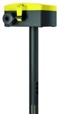
Features
• Duct sensor for measuring carbon dioxide (CO2) content for demand-based ventilation of indoor spaces
• CO2 measurement with NDIR1) Dual-beam technology, therefore stable in the long term and largely resistant to external influences
• Measurement of temperature in ventilation ducts
• Two analogue 0...10 V outputs are available: one for CO2 measurement and one for temperature measurement. This allows direct connection to an automation station
• Automatic drift compensation
• Mounting accessories and flange included
Technical data
Power supply
Outputs
Parameters
Time characteristic
CO2
Temperature
Ambient conditions
Construction
Power supply (SELV)
Power consumption
Peak inrush current
Output signal
Flow speed
Standards, directives
15…35 V= / 19…29 V~
Max. 2.3 W (24 V=) / 4.3 VA (24 V~)
1.2 A < 3 ms
2 × 0…10 V, load min.: 10 kΩ
Min. 0.3 m/s, max. 12 m/s
In moving air (3 m/s) 5 minutes
Measuring range
Measuring accuracy
Measuring range
0…2000 ppm
±50 ppm drift over the serviceable life
+3% of the measured value (typical at 21 C, 50% rh)
0…50 °C
Measuring accuracy ±0.5 K (typical at 21 °C)
Ambient temperature 0...50 °C
Ambient humidity Max. 85% rh non-condensing
Connection terminals
Cross-section of cable
Cable inlet
Plug-in female connectors, removable
Max. 2.5 mm²
Removable insert, M20 for cable, min. Ø 4.5 mm, max. Ø 9 mm
Housing Yellow/black
Housing material
Filter unit material
Housing: PC, sensor tube: PA6
Stainless steel, wire mesh
Sensor tube diameter 19.5 mm
Sensor tube length 180 mm
Weight 150 g
Type of protection
Instrument head: IP65 (EN 60529)
CE conformity according toEMC Directive 2014/30/EUEN 60730-1 (mode of operation 1, residential premises)
RoHS Directive 2011/65/EUEN IEC 63000
1) NDIR: Non-dispersive infrared sensor

Overview of types
Type Features
EGQ212F032Duct transducer, CO2 and temperature; 2 × 0...10 V
Accessories
Type Description
0300360003Mounting flange, plastic
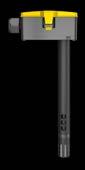
Features
• Duct air quality sensor for detection of volatile organic compounds (VOC) for demand-controlled ventilation of indoor spaces. VOC sources include flue gases, solvents as well as various cleaning agents and building materials
• Measurement of temperature in ventilation ducts
• Two analogue 0...10 V outputs are available: one for VOC measurement and one for temperature measurement. This allows direct connection to an automation station
• Automatic calibration via an integrated algorithm
• Mounting accessories and flange included
Technical data
Power supply
Outputs
Parameters
Time characteristic
VOC
Temperature
Ambient conditions
Construction
Power supply (SELV)
Power consumption
Peak inrush current
Output signal
Flow speed
Standards, directives
15…35 V= / 19…29 V~
Max. 2.3 W (24 V=) / 4.3 VA (24 V~)
1.2 A < 3 ms
2 × 0…10 V, load min.: 10 kΩ
Min. 0.3 m/s, max. 12 m/s
In moving air (3 m/s) 5 minutes
Measuring range 0...100%
Serviceable life
Typically 10 years
Sensor Heated tin dioxide semiconductor
Measuring range
Measuring accuracy
Ambient temperature
0…50 °C
±0.5 K (typical at 21 °C)
0...50 °C
Ambient humidity Max. 85% rh non-condensing
Connection terminals
Cross-section of cable
Cable inlet
Plug-in female connectors, removable
Max. 2.5 mm²
Removable insert, M20 for cable, min. Ø 4.5 mm, max. Ø 9 mm
Housing Yellow/black
Housing material
Filter unit material
Sensor tube diameter
Housing: PC, sensor tube: PA6
Stainless steel, wire mesh
19.5 mm
Sensor tube length 180 mm
Weight 150 g
Type of protection
Instrument head: IP65 (EN 60529)
CE conformity according toEMC Directive 2014/30/EUEN 60730-1 (mode of operation 1, residential premises)
RoHS Directive 2011/65/EUEN IEC 63000
Overview of types
Type Features
EGQ110F032Duct transducer; VOC and temperature; 2 × 0...10 V

Accessories
Type Description
0300360003Mounting flange, plastic
SAUTER humidity sensors are used for the energy-efficient control and monitoring of ventilation systems. Sensors are available for measuring the relative humidity and enthalpy of the air. They can be used in residential or business premises and can also be fitted in air ducts.
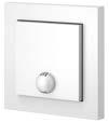
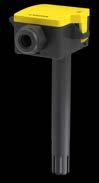
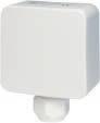
EGH120F042
EGH130F032
Features
• Measurement of humidity via a fast, capacitive sensor
• Active measuring element
• Suitable for direct wall mounting and recessed junction boxes
• Converts the measured values into a continuous analogue signal (0...10 V / 4...20 mA)
Technical data
Parameters
Relative humidity
Temperature
Ambient conditions
Construction
Standards, directives
Measuring range 0...100% rh, no condensation
Measuring accuracy ±2 % between 10…90 % rh (typ. at 21 °C)
Measuring range 0…50 °C
Measuring accuracy ±0.5 °C (typ. at 25 °C)
Ambient temperature −35…70 °C
Ambient humidity Max. 85% rh, non-condensing
Colour
Traffic white (RAL9016)
Housing material Polycarbonate (PC) UL94-V0
Cable inlet Through the rear wall
Connection terminals Spring-type terminals, max. 1.5 mm2
Weight 80 g
Type of protection
IP20 (EN 60529) after fitting CE/UKCA conformity1)
EMC-D 2014/30/EU (CE)EN 60730-1 (mode of operation 1, residential premises)
EMC-2016 (UKCA) See EMC Directive
RoHS-D 2011/65/EU & 2015/863/EU (CE)
EN IEC 63000
RoHS-2012 (UKCA) EN IEC 63000
Overview of types Type
EGH120F042Room
EGH130F032Room
Accessories
Type
0300230010 USB Bluetooth® dongle

1) Explanation of abbreviations in the “Additional technical information” section of the product data sheet and in the appendix to SAUTER product catalogues
EGH 681: Room transducer, relative humidity and temperature, recessed
Features
• Measures the relative humidity and temperature in rooms
• Regulation of the room climate in combination with room automation systems
• Fast response time and high precision
• Including frame
Technical data
Power supply
Output signal
Parameters
Ambient conditions
Construction
Standards, directives
Power supply 15...24 V= (±10%) or 24 V~ (±10%)
Power consumption Typ. 0.3 W / 0.5 VA
Output signal
0...10 V, load resistance at least 10 kΩ
Measuring range, temperature0...50 °C
Measuring range, humidity0...100% rh
Ambient temperature −20...70 °C
Housing
Housing material
Pure white
Lower section: ABS
Front plate: PC
Frame design Gira E2
Weight 80 g
Type of protection
IP30 (EN 60529)
CE conformity according toRoHS Directive 2011/65/EUEN IEC 63000
EMC Directive 2014/30/EUEN 60730-1 (mode of operation 1, residential premises)
Overview of types
Type Description
EGH681F031Room transducer, relative humidity and temperature, recessed

Features
• Active measurement of relative and absolute humidity, enthalpy, dew point and air temperature
• EGH111F032: Also with Ni1000 passive temperature sensor
• Measurement by means of fast capacitive measuring element
• Sensor immersion length 138 mm
• Cable inlet via a removable cable gland
• Mounting set and mounting flange included
• Can be used in damp and dusty environments (type of protection IP65)
Technical data
Power supply
Parameters
Relative humidity
Absolute humidity
Enthalpy
Dew point
Temperature
Power supply
Power consumption
Measuring range
Measuring accuracy
Measuring range
15…24 VDC (±10%) or 24 VAC (±10%) SELV
Typ. 0.4 W (24 VDC) or 0.8 VA (24 VAC)
0...100% rh, no condensation
±2% between 10…90% rh (typ. at 21 °C)
0…50 g/m³ (factory setting) switchable to 0…80 g/m³
Measuring range 0...85 kJ/kg
Measuring range 0…50 °C (factory setting) switchable to -20…+80 °C
Measuring range -20…80 °C (factory setting) switchable to 0…50 °C, -15…35 °C or -40…60 °C
Measuring accuracy1) ±0.3 K, typ. at 21 °C (factory settings)
Time constant in moving air (3 m/s)2 minutes (t63)
Flow speed
Ambient conditions
Outputs
Min: 0 m/s
Max: 12 m/s
Ambient temperature -20…70 °C
Humidity (non-condensing)85% rh
Output signal
Construction
Colour
Housing material
Filter unit material
Cable inlet
Connection terminals

2 × 0…10 V (factory setting), min. load 10 kΩ, switchable to 2 × 0…5 V
Black/yellow
Polycarbonate (PC) UL94-V0
Stainless steel, wire mesh (1.4401)
M20 for cables with Ø 4.5...9 mm, removable
Plug-in connector, removable, max. 2.5 mm²
Dimensions W × H × D 65 × 41 × 70 mm (without sensor tube and cable gland)
Sensor tube length 138 mm
1) The specified measuring accuracy only applies to the measuring element. The actual accuracy also depends on the cable length
Standards, directives
Sensor tube diameter
19.5 mm Weight 164 g
Type of protection2) IP65 (EN 60529)
CE conformity according toEMC Directive 2014/30/EUEN 60730-1, EN 61000-6-1, EN 61000-6-3
RoHS-D 2011/65/EU & 2015/863/EU
EN IEC 63000
Overview of types
Type Description
EGH111F032Duct transducer for relative and absolute humidity, enthalpy, dew point, temperature, 2 × 0…10 V, Ni1000
EGH112F032Duct transducer for relative and absolute humidity, enthalpy, dew point, temperature, 2 × 0…10 V.
2) The type of protection IP65 is also guaranteed without screwing on the housing cover. The screw supplied serves as additional protection against manipulation of the device
Features
• Measures the enthalpy and temperature in air ducts
• Measurement by means of fast capacitive measuring element
• Active measuring element
• Unaffected by flow speeds and normal contamination
• Mounting flange supplied
Technical data
Power supply
Power supply
Power consumption
Outputs
Parameters
Time characteristic
Enthalpy
Temperature
Ambient conditions
Construction
15...24 V= (±10%) or 24 V~ (±10%)
Max. 0.4 W (24 V=) | 0.8 VA (24 V~)
Output signal 2 x 0...10 V (min. load 10 kΩ)
Flow speed
Min. 3 m/s
Max. 10 m/s
Time constant in moving air (3 m/s)3 minutes
Measuring range 0...100 kJ/kg
Measuring accuracy 3.5 kJ/kg (typ. at 21 °C)
Measuring range −20...80 °C
Measuring accuracy ±0.5 °C (typ. at 25 °C)
Ambient temperature −20...70 °C
Connection terminals
Screw terminal, max. 1.5 mm2
Cable inlet M20 for cable Ø min. 5.8 mm, max. 10 mm
Housing
Yellow/black
Housing material PA6
Filter unit material
Sensor tube diameter
Standards, directives
Stainless steel, wire mesh
19.5 mm
Sensor tube length 140 mm
Weight 120 g
Type of protection
Instrument head: IP65 (EN 60529)
CE conformity according toEMC Directive 2014/30/EUEN 60730-1 (mode of operation 1, residential premises)
RoHS Directive 2011/65/EUEN IEC 63000
Overview of types
Type Description
EGE112F031Duct transducer, enthalpy and temperature, 2 x 0...10 V

Features
• Protects against dew formation on chilled ceilings
• Controls a regulating unit via a holding relay that interrupts the cooling water flow or increases the cooling water temperature
• Best solution for monitoring chilled-ceiling systems
• Measurement taken by a spring-mounted dew point sensor
• Active measuring element
• Variant with external sensor (EGH102F101)
• Holding relay with changeover contacts
• Includes retaining strap for pipes of Ø 10...100 mm and heat-conducting paste
Technical data
Power supply
Parameters
Ambient conditions
Inputs/outputs
Construction
Power supply
Power consumption
Measuring range
Changeover contact1)
Response time in still air
Exposure to dew
Switching difference
Switching point
Ambient temperature
Output signal
Screw terminals
Housing
Housing material
Weight
Standards and directives
24 V~/=, ±20%
Max. 1 VA
70...85% rh
1 A, 24 V~/=
80 to 99% rh, 99 to 80% rh, max. 3 minutes
Max. 30 min
Fixed, approx. 5% rh
95 ±4% rh
5...60 °C
Approx. 70...85% rh, 0...10 V, load > 10 kΩ
For electrical cables of up to 1.5 mm²
Pure white (RAL 9010)
Fire-retardant thermoplastic
0.1 kg
Cable inlet For Pg 11
Type of protection
Mode of operation
Overview of types
Type Clamp-on sensor
EGH102F001Integrated in housing
EGH102F101Cable 1 m long, sensor integrated in the cable end
IP40 (EN 60529)
Type 1 C (EN 60730)
1) When activating relays, gates etc. with cos φ< 0.3, it is recommended to use RC circuitry in parallel to the coil. This reduces contact pitting and prevents high-frequency interference

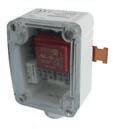
Features
• Protects against dew formation on chilled ceilings, etc.
• Controls a regulating unit via a holding relay that interrupts the cooling water flow or increases the cooling water temperature.
• Measurement is performed by a dew point sensor
• Potential-free output contact for 24 V and 230 V
• Holding relay with changeover contacts
• LED indicator for power supply and dew formation
• Plug-in connectors for electrical cables up to 1.5 mm2
• Cable inlet M20
• Fitted onto pipes using the provided cable tie for pipes Ø 10...40 mm
Technical data
Power supply
Parameters
Ambient conditions
Construction
Standards and directives
Power supply
Power consumption
230 VAC ±10%
Max. 3.5 VA
Changeover contact1) 5 A, 230 VAC
Switching point 95 ±4% rh
Switching difference Fixed, approx. 5% rh
Ambient temperature
Housing
-20...60°C (non-condensing)
Pure white, PA6
Weight 0.19 kg
Type of protection
IP 65 (EN 60529)
CE conformity according toEMC Directive 2014/30/EUEN 61000-6-1, EN 61000-6-3
Low-Voltage Directive 2014/35/EUEN 60730-1 (mode of operation 1, residential premises)
Overview of types
Type
Description
EGH103F001Dew point monitor 230 VAC
Accessories
Type
Description
0300360004Heat-conducting paste, dosing syringe with 2 g content

1) When activating relays, gates, etc. with cos φ< 0.3, it is recommended to use RC circuitry in parallel to the coil. This reduces contact pitting and prevents high-frequency interference
SAUTER flow and pressure sensors enable the accurate measurement of air pressures and flow speeds in rooms and ventilation ducts. This includes the measurement of duct pressures for precise control and monitoring of ventilation systems. Additionally, SAUTER flow and pressure sensors can also be used to measure room pressures in laboratories and clean rooms and for flow monitoring in fume cupboards.
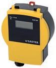
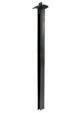
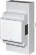
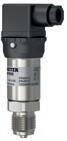
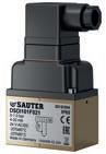
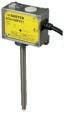
Features
• Exact measurement of positive, negative and differential pressures in gases
• Optimised for applications such as filter monitoring, room or duct pressure monitoring, level monitoring in fluids, actuating frequency converters for fan control and recording volume flow, especially for room air balancing in laboratories
• Can be ideally combined with XAFP 100 flow probe for precise measurement of volume flow
• Static pressure sensor
• Can be fitted in any position
• Can be used for dusty air or air polluted with chemicals (not ATEX approved)
• Manufacturer’s test certificate ex works
• The measuring range can be adapted optimally to the needs of the application
• Variable zero point and filter time constant to suppress pressure surges in the system
• Display shows the actual value and the signal progression (depending on type)
• Status LED for immediate indication of operating status (depending on type)
• Measuring range can be reduced to one third (depending on type)
• Fitted to either wall or DIN rail (EN 60715)
• Cover that does not require special tools to open
Technical data
Power supply
Power supply
24 V~/=, ±20%
Power consumption F**2 24 V~ 3.0 VA
Power consumption F**1
Parameters
Ambient conditions
Inputs/outputs
24 V= 1.3 W
24 V~ 1.4 VA
24 V= 0.4 W
Admissible positive pressure±20 kPa
Influence of position1) < 0.1% FS (full span)
Non-linearity 1% FS pressure-linear
Zero point stability < 0.3% FS
Reproducibility 0.2% FS
Pneumatic connection2) 6.2 mm
Parts in contact with media PC/ABS blend
Media temperature
0…70 °C
Admissible operating pressure pstat 3) ±7 kPa
Ambient temperature 0…60 °C
Ambient humidity 5...95% rh, no condensation
Output signal4)
Filter time constant

F*01: 0...10 V, load > 10 kΩ
F*02/F*12: 0(2)...10 V, load < 500 Ω
F*01: 0.05...2 s
F*02, F*12: 0.15...5.2 s
1) The sensor is calibrated at the factory for vertical fitting. The influence of position must be taken into account if the unit is not fitted in the vertical position
2) Max. length of measuring wire (di = 6.2 mm): Lmax = 15 m for time constant < 0.5 s, Lmax = 60 m for time constant > 0.5 s
3) The zero point should be recalibrated if the admissible operating pressure is exceeded
4) With a load of < 500 Ω, a change-over to 0...20 mA or 4...20 mA occurs automatically. Output protected against short circuits and excess voltage up to 24 V~
Construction
Standards, directives
Pressure connection Internal Ø 6 mm
Housing PC/ABS
Cable gland M16
Screw terminals
Type of protection
For electrical cables of up to 1.5 mm²
IP65 (EN 60529)
Protection class III (EN 60730-1)
EMC Directive 2014/30/EUEN 61000-6-1, EN 61000-6-2 EN 61000-6-3, EN 61000-6-4
Data capture | Flow and pressure
Overview of types
/ Output signal: Analogue output limited to 10.6 V. Measured values with an overrun of 6% of the measuring range can therefore be transferred
/ Variable characteristic/LED: Manual adjustment of measuring range with gain potentiometer. Signal curve: linear/rootextracted. Output signal: 0...10 V / 2...10 V via DIP switches or with CASE Sensors software
Type Measuring rangeDisplay
EGP100F101±75 Pa, ±0.75 mbar
EGP100F102±75 Pa, ±0.75 mbar
EGP100F112±75 Pa, ±0.75 mbar
EGP100F201±150, 1.5 mbar
EGP100F202±150, 1.5 mbar
EGP100F212±150, 1.5 mbar
EGP100F3010...150 Pa, 0...1.5 mbar
EGP100F3020...150 Pa, 0...1.5 mbar
EGP100F3120...150 Pa, 0...1.5 mbar
EGP100F4010...300 Pa, 0...3.0 mbar
EGP100F4020...300 Pa, 0...3.0 mbar
EGP100F4120...300 Pa, 0...3.0 mbar
EGP100F6010...1000 Pa, 0...10.0 mbar
EGP100F6020...1000 Pa, 0...10.0 mbar
EGP100F6120...1000 Pa, 0...10.0 mbar
Accessories
Type Description
0010240300Connection set, 6 mm, complete
Variable characteristic/LED
Weight (kg)
XAFP100F001Flow probe to measure the air volume in ventilation ducts
CERTIFICAT001Manufacturer’s test certificate type M
CERTIFICAT999Test for further device (from 2 pcs.)
0300360001USB-RS-485 converter
XAFP100F001
Features
• Flow probe for precise and inexpensive recording of differential pressure signals in ventilation and air conditioning systems
• Efficient regulation of applications for demand-controlled ventilation in offices, laboratories, fume cupboards and clean rooms, by combining an air damper and an electronic/pneumatic volume flow controller
• In combination with a square root differential pressure sensor, air volume flows can be reliably recorded and monitored
• Optimised flow profile for accurate measurement of differential pressure signals
• Can be used in atmospheres containing aggressive substances
• Length (396 mm) can be shortened on site if necessary
Technical data
Parameters
Admissible ambient conditions
Function
Construction
Material
Standards and directives
Flow probe
Overview of types
Type
Features
Measurement tolerance < 3%
Range (mm)
DN 80…400
Operating temperature 0...50 °C
Ambient humidity < 85% rh, no condensation
Function
Dimensions
Flow probe
65 × 40 × 396 mm (W × H × L)
Bore Ø 30...32 mm
Flow probe
Seal
XAFP100F001Flow probe for ventilation ducts Data capture | Flow and pressure
Connecting tube
Electrical
Flammability
PA 6
PE, physiologically safe
PU
UL 7468
UL 94, IEC 60695-2-12, IEC 60695-2-13

Features
• Precise and long-term stable recording of air inflow speeds in fume cupboards with a time constant of <100 ms
• Particularly suitable for fume cupboards with horizontal and vertical front sashes
• Air volume control according to needs for fume cupboards with horizontal and vertical front sashes
• Precise and long-term stable recording of air inflow speeds in fume cupboards
• Reliable detection of reversal of flow direction
• Integrated filter unit that protects against contamination of the sensor
• Dynamic pressure sensor based on thin-film technology
• Fitted to the fume cupboard simply and quickly
Technical data
Power supply
Parameters
Ambient conditions
Inputs/outputs
Standards and directives
Power supply
24 V~, -15%/+20%, 50...60 Hz
Power consumption 1 VA
Measuring range 0...1 Pa
Measuring span1) 0...1.3 m/s
Differential pressure Approx. 0...1 Pa
Time constant < 0.1 s
Air throughput rate 3 cm3/min (at 1 m/s)
Ambient temperature 5...55 °C
Ambient humidity < 90% rh
Output signal2) 0...10 V Linearity 2% (based on the output signal)
Type of protection IP40 (EN 60529) with terminal cover CE conformity according toEMC Directive 2014/30/EUEN 61000-6-1, EN 61000-6-3
Overview of types
Type Feature
SVU100F005Linear to v [m/s]
A Specified flow speed is based on ρ= 1.2 kg/m3
1) Recommended measuring span 0.2...1.3 m/s (output 2...10 V)
2) Output signal: Output protected against short circuits and excess voltage up to 24 V~ Data capture | Flow and pressure

DS*2**F002
Features
• For measuring pressure in liquids, gases and vapours
• Sturdy device with ceramic diaphragm
• High precision
• High positive pressure protection
• High vibration resistance
• Low hysteresis
• Standard signal 2...10 V or 4...20 mA
• Pressure sensor made of stainless steel for aggressive media
• With standard plug as per DIN EN 175301-803-A
Technical data
Power supply
Parameters
Power supply
Electrical connection
Temperature dependence
Admissible load
Ambient conditions
Inputs/outputs
Construction
Standards and directives
Ambient temperature
See type list
DSI: Two-wire
DSU: Three-wire
Zero point 0.07% FS/K
Measuring range 0.05% FS/K
DSU:
Ub ≥ 15 V ≥ 5 kΩ
Ub ≥ 20 V ≥ 2 kΩ
DSI: (Ub-6 V)/0.02 A
0...60 °C
Media temperature 0...85 °C
Hysteresis
Linearity
Housing material
Device plug
Cross-section of cable
< 0.5% FS
< 1% FS
Chromium-nickel steel 1.4305
Plug connection 4-pin, standard plug
DIN EN 175 01-803-A, cable gland M16
Max. 1.5 mm2
Pressure connection G ½"
Weight 0.2 kg
Type of protection
IP65 (EN 60529)
Protection class III (EN 61140)
CE conformity according toEMC Directive 2014/30/EUEN 61000-6-1 / EN 61000-6-2 EN 61000-6-3 / EN 61000-6-4 EN 60730
PED 2014/68/EU

Subject to Art. 3.3 of PED without safety function
Data capture | Flow and pressure
Overview of types
Type Measuring range (bar)
DSU203F0020...2.5 bar0...10 V24 V=/~8 bar 24 V=/~, 0.5 W (VA)
DSU206F0020...6 bar 0...10 V24 V=/~20 bar24 V=/~, 0.5 W (VA)
DSU210F0020...10 bar 0...10 V24 V=/~32 bar24 V=/~, 0.5 W (VA)
DSU216F0020...16 bar 0...10 V24 V=/~50 bar24 V=/~, 0.5 W (VA)
DSU225F0020...25 bar 0...10 V24 V=/~80 bar24 V=/~, 0.5 W (VA)
DSI203F0020...2.5 bar 4...20 mA24 V= 8 bar 24 V=, 0.7 W
DSI206F0020...6 bar4...20 mA24 V= 30 bar24 V=, 0.7 W
DSI210F0020...10 bar4...20 mA24 V= 32 bar24 V=, 0.7 W
DSI216F0020...16 bar4...20 mA24 V= 50 bar24 V=, 0.7 W
DSI225F0020...25 bar4...20 mA24 V= 80 bar24 V=, 0.7 W
Accessories
Type Description
0300360007Capillary throttle, stainless steel, length 1 m, G½"-G½"
0300360015Wall holder for DSU/DSI
DSD*10*F021
Features
• For measuring pressure differences in liquids, gases and vapours
• Pressure measuring in non-aggressive fluids or gaseous media
• Sturdy device with ceramic diaphragm
• For use in filter technology, heating systems etc.
• Differential pressure measuring range from 0...6 bar
• Analogue signal 0...10 V or 4...20 mA
• 24 V~/= supply voltage
• With fitting bracket
• Standard plug as per DIN EN 175301-803-A
Technical data
Power supply
Parameters
Ambient conditions
Construction
Standards and directives
Power supply 24 V=/~, ±20%, (50...60 Hz)
Electrical connection Three-wire
Power consumption < 1.5 W (VA)
Output signal 0...10 V Load: > 2 kΩ 4...20 mA
Load: ≤ 700 Ω (V=), ≤ 400 Ω (V~)
Accuracy1) ≤ 1%
Ambient temperature -20...80°C
Media temperature 0...80°C (non-freezing media)
Ambient humidity 45...75% rh
Burst pressure 64 bar (both sides)
Housing material Brass
Diaphragms Ceramic
Connection thread G ⅛" (female thread)
Device plug
Plug connection 4-pin, standard plug DIN EN 175 01-803-A, cable gland M16
Weight 0.62 kg
Type of protection IP65 (EN 60529)
CE conformity according toEMC Directive 2014/30/EUEN 61326-1, EN 61326-2-3
PED 2014/68/EU Fluid group II, article 4.3

Overview of types
Type Measuring range ∆pOutput signal Max. pressure (connection +) Max. pressure (connection -)
DSDI101F0210...1 bar 4...20 mA 10 bar 5 bar
DSDI103F0210...2.5 bar 4...20 mA 21 bar 15 bar
DSDI106F0210...6 bar 4...20 mA 21 bar 15 bar
DSDU101F0210...1 bar 0...10 V 10 bar 5 bar
DSDU103F0210...2.5 bar 0...10 V 21 bar 15 bar
DSDU106F0210...6 bar 0...10 V 21 bar 15 bar
1) Including non-linearity and hysteresis in compensated temperature range 10...70°C
Data capture | Flow and pressure
Accessories
Type Description
0300360005Cutting ring fitting G⅛" to 6 mm pipe (2 pcs)
0300360006Pneumatic fitting G⅛" to 6 mm hose (2 pcs)
0300360016Throttle screws G⅛", G⅛" (2 pcs)
Features
• Infinitely-variable measurement of the position of the vertical front sash on laboratory fume cupboards
• Accurate detection of sash position, with no wear and tear
• Fast control of the air volume; no oscillation
• Easy fitting, preferably on the counterweight of the front sash
• Teach-in function for adjusting the travel of the front sash
• Easy to program using the SAUTER CASE Sensors software
• Integrated excess-travel alarm
• Power cable 2.5 m long, 7 × 0.32 mm2, fixed to housing
• Fitted with halogen-free cable as standard
• Remote access and remote maintenance: Commissioning and service via bus or external push-button
• 3-colour LED status indicator
• Acoustic status and alarm elements (can be deactivated)
Technical data
Power supply
Parameters
Ambient conditions
Inputs/outputs
Power supply 24 VAC ±20%, 50...60 Hz
Power supply 24 VDC ±20%
Power consumption 24 VAC1) Typically: 2 VA, 0.75 W, inactive buzzer, max.: 4 VA, 1.5 W, active buzzer
Power consumption 24 V=2) Typically: 0.6 W, inactive buzzer, max.: 1.1 W, active buzzer
Linearity error
Max. 1.5% based on working range, e.g.: 2...10 V = 8 V
Hardware response time3) < 100 ms
Filter time constant 0...5, 22 s, variable using SAUTER CASE Sensors
Operating temperature 0...55 °C
Storage and transport temperature–20...70 °C
Air humidity 85% rh, no condensation
Digital input Iout_source max.: 1 mA, Vout max.: 18 V at Rload = ∞
Alarm output Isink max.: 2 mA, open collector output, 100 mV at Isink 2 mA, Vin max.: 24 V=, 20% at Isink = 0 mA
Voltage output4) 0/2...10 V, 1 mA max., Vout max.: 11.5 V, can be parametrised, Default 2...10 V
Typical overall error 2.5% (unlinearity, hysteresis, offset, amplified; based on working range)
Effect of temperature < 0.04 %/K

1) Default is buzzer active
2) Inactive/active buzzer: Default is buzzer active
3) The set filter time constant must be added
4) Protected against short circuits and excess voltage to 24~
Construction
Standards and directives
Overview of types
Type Working range
Weight 0.68 kg
Length of cable without bus termination5) Up to 200 m, Ø 0.5 mm
Type of protection
IP10 (EN 60529, IP20 (EN 60529)
Protection class III (EN 60730)
Software A (EN 60730)
EMC Directive 2014/30/EUEN 61000-6-1, EN 61000-6-2 EN 61000-6-3, EN 61000-6-4
Resolution of working stroke
SGU100F010200…800 mm for bench-mounted fume cupboards (max. spring travel 1000 mm) < 1 mm
SGU100F011400…1600 mm for walk-in fume cupboards (max. spring travel 2000 mm) < 2 mm
Accessories
Type Description
0300360001USB-RS-485 converter
For all building situations: stand-alone or networked.
SAUTER stand-alone controllers are tailored to applications such as heating, air-conditioning, ventilation or room control. They can be installed quickly. The intuitive operating concept ensures maximum comfort and guarantees, at the same time, the greatest possible energy efficiency in day-to-day operations. This allows all requirements for smooth functionality and economical operation to be combined.
flexotron
VAV compact controllers
The SAUTER single-room controller combines the highest standards of operability with a modern design. The device can be used in various applications in hotel, business or residential premises. These include individual temperature control for single rooms, apartments and zones in 2- and 4-pipe systems. The electronic room controller is powerful, economical and easy to operate.

Type designation
Application
Air-conditioning controller
For 2-pipe installation
For 4-pipe installation
For 2/3-way zone valve
For 6-way ball valve Outputs
Quasi-continuous, 2-point
and indicator
Further information Page 91
Single-room, heating and air-conditioning controllers | Single-room control
Features
• Single-room controller for heating and cooling by means of air conditioning units in commercial and residential buildings
• For 2- or 4-pipe fan coil units, two-stage heating systems or water-bearing heat pumps
• Can be integrated into building management systems via Modbus/RTU
• Large configurable display with backlight
• Integrated ON/OFF timer
• Deactivatable button operation for public installations
• Valve control via 2-point or 0...10 V output
• Supports 3-speed fans or fans with EC motor
• Summertime/wintertime change-over in 2-pipe applications
• Automatic deactivation of internal temperature sensor when using a cable temperature sensor
• Installation via mounting plate without opening the controller
• Universal design and low installation height of 14 mm for inconspicuous fitting
Technical data
Power supply
Ambient conditions
Inputs/outputs
Inputs
Outputs
Interfaces, communication
Power supply
100…240 V~, 50/60 Hz
Power consumption 5 VA
Ambient temperature
0…40 °C
Ambient humidity 10…90% rh, no condensation
Storage and transport temperature-10…60 °C
Temperature sensor NTC 10k
Digital input closed < 0.3 V= open > 0.7 V=
Analogue input 0…10 V
Analogue output U 0…10 V (100 kΩ)
Relay output 2.2 A (IR); 3.6 A (IX) cos φ 0.98 each at 240 V~
RS-485 Communication protocol Modbus/RTU
Connection
Screw terminal, 3-pole 0.14...1.5 mm² rigid A (D+) / B (D-)
Bus speed 4800, 9600 bit/s (adjustable)
Address range 164
Function codes 01, 03, 04, 06, 16
CRC check CRC-16
Data type u16
Data format
Construction
10 bit, 1 start, 8 data, 1 stop, no parity
Display LCD display with backlight (adjustable)
Buttons 6
Weight
0.3 kg
Dimensions W × H × D 88 × 88 × 46.2 mm
Housing
Upper and lower part white
Housing material Polycarbonate
Fitting On round or square recessed box

Standards, directives
Type of protection IP20 (EN 60529)
Protection class II as per IEC 60730
CE conformity according toEMC Directive 2014/30/EUEN 60730-1, EN 60730-2-9 residential premises Type1.C Low-Voltage Directive 2014/35/EUEN 60730-1, EN 60730-2-9 RoHS Directive 2011/65/EUEN IEC 63000
Inputs/outputs
Type AI
NRFC413MF1111 × NTC, 1 × 0...10 V113 × relay (single-pole normally-open contact)
NRFC422MF1111 × NTC
NRFC423MF1111 × NTC
NRFC424MF1121 × NTC
Type
Description
105 × relay (single-pole normally-open contact)
123 × relay (single-pole normally-open contact)
123 × relay (single-pole normally-open contact)
NRFC413MF111 2-pipe, continuous, with positional feedback signal3 speeds
NRFC422MF111 2-pipe or 4-pipe, 2-point 3 speeds
NRFC423MF111 2-pipe or 4-pipe, continuous 3 speeds
NRFC424MF112 2-pipe or 4-pipe, 2-point or 2-pipe, continuousEC motor with cut-off function
The systems and solutions from SAUTER set standards for convenient control of surface heating and cooling systems. The products stand for technologically advanced, precise and easy to operate installations. The systems provide modern solutions for single- and multi-family buildings, hotels and public buildings, where the focus is on optimal comfort, easy operation and energy efficiency.
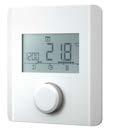
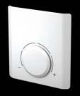
Single-room, heating and air-conditioning controllers | Single-room control
Features
• Electronic room thermostat for 24 V or 230 V for heating or heating/cooling with display
• Easy to read LCD with backlight on TRA 421
• Silent-switching Triac output (24 V types)
• Easy to wire up
• NTC sensor
• Time programme and pilot clock output integrated in TRA 421
• Optimised time programme for comfort control and energy saving
• Input for lowering the room temperature (TRA 410)
• Input for heating/cooling changeover (TRA 421)
• Input for external temperature sensor
• Cooling lock function on versions for heating/cooling
• Integrated “NC” and “NO” changeover
• Modern design with ergonomic setpoint adjuster
• Restriction of temperature setting range
• Automatic frost protection facility at 5 °C and valve protection facility
Technical data
Power supply
Power supply
Power consumption
Fuse
Parameters
Number of actuators
Setting range
Switching difference
Set-back
Ambient conditions
Construction
Inputs/outputs
See type list
< 0.3 W in idle state
In housing:
230 V= T1AH
24 V= T1A
AXT:
230 V, max. 5 pcs. parallel
24 V, max. 4 pcs. parallel
5...30 °C
±0.2 K
2 K or adjustable
Measuring element NTC 22k
Ambient temperature
Ambient humidity
Housing
Housing material
Fitting
Switching element
Switch rating
ECO input
0...50 °C
5...80% rh, no condensation
Cover: White (RAL 9016)
Lower section: Signal white (RAL 9003)
Thermoplastic PC + ABS
Wall, recessed junction box
230 V, relay
24 V, Triac
230 V, 1 A
24 V, 1 A
230 V, voltage detection 230 V
24 V, voltage detection 24 V

Single-room, heating and air-conditioning controllers | Single-room control
Heating/cooling
Pilot timer
Connection terminals / cable
Connection terminals
Power cable
Standards, directives
Type of protection
Input:
230 V, voltage detection 230 V
24 V, voltage detection 24 V
Output:
230 V, 100 mA
24 V, 100 mA
Screw terminals
0.22 mm2 to 1.5 mm2
Solid: NYM-J/NYM-O (max. 5 × 1.5 mm²)
Flexible: H03V2V2H2-F / H05V2V2H2-F
IP20 (EN 60529)
Protection class 24 V III (EN 60730)
Protection class 230 V II (EN 60730)
CE conformity according toEMC Directive 2014/30/EUEN 61000-6-1, EN 61000-6-3
Low-Voltage Directive 2014/35/EUEN 60730-1, EN 60730-2-9
Overview of types
Type
TRA410F210Heating,
TRA410F212Heating, lowering, frost protection function
TRA421F210Heating/cooling, lowering, frost protection and valve protection function, cooling lock
TRA421F212Heating/cooling, lowering, frost protection and valve protection function, cooling lock
Accessories
Type Description
±10%, 50 Hz140 g
±10%, 50 Hz140 g
AXT3**Thermal actuators for unit valves (see product data sheet)
EGT554F103Cable temperature sensor, NTC 22k, -35...100 °C, IP67, length 3 m
Single-room, heating and air-conditioning controllers | Single-room control
TRT 317, 327: Electronic room thermostat for heating and heating/cooling
Features
• Electronic room thermostat for 24 V or 230 V for heating or heating/cooling
• Silent-switching Triac output on 24 V types
• Easy to wire up
• NTC sensor
• With input for lowering the room temperature
• With input for heating/cooling changeover (TRT 327)
• With cooling lock function on versions for heating/cooling
• Modern design with ergonomic setpoint adjuster
• With restriction of temperature setting range
• Electrical connection in baseplate with screw terminals
• With automatic frost protection facility at 8 °C and valve protection function
Technical data
Power supply
Power supply
Power consumption
Fuse
Parameters
Ambient conditions
Construction
Inputs/outputs
Connection terminals / cable
Number of actuators
Setting range
Switching difference
24 V~ / 230 V~
< 0.3 W in idle state
In housing:
230 V= T2AH
24 V= T1A
AXT:
230 V, max. 6 pcs. parallel
24 V, max. 4 pcs. parallel
10...28 °C
±0.5 K
Set-back 2 K
Measuring element NTC
Ambient temperature
0...50 °C
Ambient humidity 5...80% rh, no condensation
Housing
Housing material
Cover: White (RAL 9016)
Lower section: Signal white (RAL 9003)
Thermoplastic PC + ABS
Fitting Wall, recessed junction box
Switching element
Switch rating
ECO input
Heating/cooling
230 V, relay 24 V, Triac
230 V, 1.8 A
230 V, voltage detection 230 V 24 V, voltage detection 24 V
230 V, voltage detection 230 V 24 V, voltage detection 24 V
Connection terminals Screw terminals 0.22mm2 to 1.5mm2
Switching difference
Cord grip
±0.5 K
External

Standards, directives
Type of protection IP20 (EN 60529)
Protection class 24 V III (EN 60730)
Protection class 230 V II (EN 60730)
CE conformity according toEMC Directive 2014/30/EUEN 61000-6-1, EN 61000-6-3 Low-Voltage Directive 2014/35/EUEN 60730-1, EN 60730-2-9
Overview of types
Type Description
TRT317F210Heating, lowering, frost protection function
TRT317F212Heating, lowering, frost protection function
TRT327F210Heating/cooling, lowering, frost protection and valve protection function, cooling lock
TRT327F212Heating/cooling, lowering, frost protection and valve protection function, cooling lock
Accessories
± 10 %, 50 Hz90 g
± 20 %, 50 Hz90 g
± 10 %, 50 Hz135 g
± 10 %, 50 Hz135 g
Type Description AXT3**Thermal actuators for unit valves (see product data sheet)
heating and
Features
• For easy wiring of up to 6 or 10 zones in a surface heating system
• For transferring switching signals from the unitary controllers for heating or heating/cooling
• Individual forwarding of time commands or night set-back to the appropriate actuators; max. 2 timer channels
• With pump and boiler control
• Pump logic with adjustable follow-on time for actuating the circulation pump
• Integrated valve protection function
• Input for temperature limiter or dew point monitor
• LED status indicator
• Pump control direction switching for NC/NO actuators
• For connecting up to 18 actuators
• Cable guidance, standard-compliant cord grip and screwless terminal connections
• Easy, intuitive wiring and installation
Technical data
Power supply
Parameters
Ambient conditions
Inputs/outputs
Outputs
Inputs
Construction
Connection terminals / cable
Power supply 230 VAC ±10%, 50...60 Hz
Power supply 24 VAC ±20%, 50...60 Hz
Distributor fuse 24 V T2A
Distributor fuse 230 V T4AH
Circuits/zones 6 or 10
Timer channels/set-back 2
Ambient temperature
Storage temperature
0...50 °C
–20…70 °C
Ambient humidity < 80% rh
Number of actuators
Pump connection
Boiler connection
Set-back
Heating/cooling
TB or dew point
Housing material
Cover
Fitting
Connection terminals
Power cable
Cable clamping device
6 channels: Max. 15 pcs.
10 channels: Max. 18 pcs.
Max. 6 (2) A
Max. 6 (2) A
Potential-free contact input
Potential-free contact input
Potential-free NC contact
Flame-retardant ABS plastic, black RAL9005
Transparent grey plastic
Mounted unit, DIN rail
Terminals with spring technology for 0.2 to 1.5 mm² vertical cable entry
Solid:
NYM-J/NYM-O (max. 5 × 1.5 mm²)
Flexible:
H03V2V2H2-F / H05V2V2H2-F
Integrated in housing

Standards, directives
CE conformity
Overview of types
Type of protection
IP20 (EN 60529)
Protection class II (EN 60730)
EMC Directive 2014/30/EUEN 60730-1 Type 1C
Low-Voltage Directive 2014/35/EUEN 60730-1 & -2-9 Type 1C
Type Nominal voltageFeatures
ChannelsWeight
FXV3006F00124 V~ / 230 V~Heating, with decrease6482 g
FXV3110F001230 V~Heating/cooling, with decrease and pump control 10515 g
FXV3110F00224 V~Heating/cooling, with decrease and pump control 10515 g
FXV3210F001230 V~Heating/cooling, with decrease, pump logic, boiler control and LED indicator 10550 g
FXV3210F00224 V~Heating/cooling, with decrease, pump logic, boiler control and LED indicator 10534 g
Accessories
Type Description 0450573001Transformer 230 / 24 V, 42 VA
Features
• For the control of a maximum of twelve thermal actuators for unit valves and the connection of up to eight room thermostats
• Flexible assignment of the actuators to the room thermostats via rotary switch
• Distribution of the power supply, the positioning signals and a shared time programme for room operating units
• Easy-to-change channel assignment without rewiring
• Pump logic module for activating a circulation pump
• Input for timer for individual forwarding of time commands to the heating zones
• LED status indicators for power supply, pump logic module and active heating channels
• Integrated cable guides and terminal connection without tools
• Fitting on DIN rail or wall mounting
Technical data
Power supply
Parameters
Ambient conditions
Inputs/outputs
Outputs
Inputs
Construction
Power supply
1)
Connection terminals / cable
230 V~, ±10%, 50...60 Hz
Distributor fuse 230 V T4AH (5 × 20 mm)
Control loops/heating zones1)
Max. 8 inputs
Timer channel/set-back Yes
Ambient temperature
Storage temperature
Ambient humidity
Number of actuators
Pump connection
Set-back
Housing material
Cover material
Fitting
Dimensions W × H × D
Connection terminals
Cross-section of cable
Power cable
Cable clamping device
0...50 °C
−20...70 °C
10...85% rh
Max. 12 thermal actuators for unit valves (for heating circuits)
Max. 2 (1) A
Contact input
PC-ABS plastic, black (similar to RAL9005)
Fire-retardant as per UL94V-0
PC plastic, grey transparent
Fire-retardant as per UL94V-0
Mounted unit, DIN rail, 35 mm or optionally screw-on mounting
350 × 100 × 52 mm
Spring-loaded plug-in connectors
0.5...1.5 mm²
Solid: NYM-J/NYM-O
(max. 5 × 1.5 mm²)
Flexible: H05V2V2H2-F
Cable fastening points integrated without tools into housing

Single-room, heating and air-conditioning controllers | Single-room control
Standards, directives
CE conformity
Overview of types
Type of protection
IP20 (IEC 60730)
Protection class II (EN 60730)
EMC Directive 2014/30/EUEN 60730-1, residential premises
Low-Voltage Directive 2014/35/EUEN 60730-1 & -2-9 Type 1C
Type Nominal voltageFeatures ChannelsWeight
FXV3308F011230 V~Heating/cooling, with decrease, pump logic and LED indicator 8580 g
SAUTER heating controllers of the equitherm series are easy to operate, while ensuring that your installation meets the highest standards of energy-optimised operation. Using communication accessories, the devices can be networked together in larger plants or integrated into a building automation system. The applications for these heating controllers include weather-dependent boiler and/or supply temperature control and domestic hot water preparation, as well as heating control in local or district heating networks.
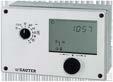
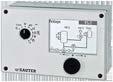
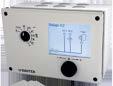
Single-room, heating and air-conditioning controllers | equitherm heating control
EQJW126F001
Features
• PI supply temperature control by heating curve or 4-point characteristic
• Convenient to use with modern operating concept (turn and press) and large LCD
• Convenient weekly and annual switching programmes with optimisation of switching times
• Automatic summertime/wintertime changeover
• Min./max. limitation of supply temperature and max. limitation of return temperature
• Frost-protection facility and pump and valve anti-jamming function
• Function heating (floor-drying function)
• Room temperature switching using room temperature sensor
• Ni/Pt1000 inputs for the outside, supply, return flow and room temperature
• Relay outputs with varistor suppression for activating control units and pump
• Manual mode
• Electrical connection in baseplate
• Interface for various accessories such as modem, gateway, data logging module etc.
Technical data
Power supply
Parameters
Control parameters
Temperature ranges
Power supply 230 V~, ±15%, 50...60 Hz
Power consumption Approx. 1.5 VA
Amplification KP 0.1...50
Integral action time 1...999 seconds
Frost-protection temperature3 °C
Normal temperature 0...40 °C
Reduced temperature 0...40 °C
Supply temperature −5...150 °C
Outdoor temperature −50...50 °C
Cycle time
Ambient conditions
Inputs/outputs
Function
Digital timer for weekly/annual switching programme

Running time of the valve ÷ 15
Running time of valve 30...300 seconds
Ambient temperature 0...40 °C
Ambient humidity 5...95% rh, no condensation
Storage and transport temperature−10...60 °C
Number of inputs 3 analogue, Ni1000/Pt1000
Number of outputs 3 relays
Pump relay1) 1 × 2 A, 250 V~, cos φ > 0,5
Actuator relay (3-point or 2-point)2) 2 × 2 A, 250 V~, cos φ > 0,5
Backup power supply
Accuracy
Min. 24 hours, typically 48 hours
< 10 minutes/year
Weekly switching programmeNumber of switching commands42/week
Min. switching interval 15 minutes
Annual switching programmeNumber of switching commands20
Min. switching interval 1 day
1) Start-up current max. 16 A (1 second)
2) Extra low voltage not admissible
Interfaces and communication
Construction
Standards and directives
Interface RJ45
Protocol Modbus, device bus (TAP)
Weight
Dimensions
0.5 kg
144 × 98 × 54 mm
Housing Light-grey
Housing material
Fitting
Screw terminals
Type of protection (when fitted in panels)
Fire-retardant thermoplastic
Wall, switch panel, DIN rail
For electrical cables of up to 2.5 mm²
IP40 (EN 60529)
Protection class II (IEC 60730-1)
Software class A (IEC 60730-1, Appendix H)
CE conformity according toEMC Directive 2014/30/EUEN 61000-6-1, EN 61000-6-3
Low-Voltage Directive 2014/35/EUEN 60730-1
Overview of types
Type Features
EQJW126F001Heating controller with digital user interface
Accessories
Type Description
AVF***Motorised valve actuator (see product data sheet)
AVM***Motorised valve actuator (see product data sheet)
AXM***Motorised valve actuator (see product data sheet)
EGT***External temperature sensor Ni1000 (see product data sheet)
0440210001Communication module for connecting EQJW 126/146 controllers to RS-232 (PC) 0440210002Communication module for connecting EQJW 126/146 controllers to modem 0440210003Communication module for connecting EQJW 126/146 controllers to RS-485 bus
0440210004Communication module for connecting EQJW 126/146 controllers to RS-485 bus (master) 0440210005ModBus-TCP gateway
0440210011ModBus-GPRS gateway 0440210006ModBus-MBus gateway 0440210007Converter/repeater for RS-232 or RS-485 interfaces 0440210008RS-485 overvoltage protection
0440210010Parameter storage module for transferring controller parameters 0440210012Cable converter, 2 conductors, RS-485
Single-room, heating and air-conditioning controllers | equitherm heating control
EQJW146F002
Features
• Weather-dependent supply temperature control by heating curve or 4-point characteristic and drinking water heating
• 29 system models, for example for district heating, single-stage boilers, drinking water heating with solar energy or buffer tank
• Convenient to use with modern operating concept (turn and press) and large LCD
• Convenient weekly and annual switching programmes with optimisation of switching times
• Automatic summertime/wintertime changeover
• Min./max. limitation of supply temperature and max. limitation of return temperature
• Frost-protection facility and anti-jamming function for valve and pump
• Floor-drying function
• Function for protecting against legionellae
• Room temperature switching using room-temperature sensors
• Ni/PT1000 inputs for the outside, supply, drinking water, return flow and room temperature
• Relay outputs with varistor suppression for activating control units and pumps
• Manual mode
• Logbook
• Configurable input/output 0...10 V
• External demand processing, binary or analogue (0..10 V)
• Interface for various accessories such as modem, gateway, data logging module etc.
Technical data
Power supply
Parameters
Control characteristic
Control parameters
Temperature ranges
Power supply 230 V~, ±15%, 50...60 Hz
Power consumption Approx. 1.5 VA
Supply temperature PI control
Drinking water temperature2-point
Amplification KP 0.1...50
Integral action time 1...999 seconds
Switching difference for drinking water1...30 K
Normal temperature 0...40 °C
Reduced temperature 0...40 °C
Supply temperature 0...140 °C
Return temperature 0...140 °C
Outdoor temperature −50...50 °C
Drinking water temperature20...90 °C
Frost-protection temperature−15...3°C
Running time of valve 30...300 seconds
Cycle time
Ambient conditions
Inputs/outputs

Running time of the valve ÷ 15
Ambient temperature 0...40 °C
Ambient humidity 5...95% rh, no condensation
Storage and transport temperature−10...60 °C
Number of outputs
1) Start-up current max. 16 A (1 second)
7 relays
Pump relay1) 3 × 2 A, 250 V~, cos φ > 0,5
Function
Timer
Actuator relay2) 4 × 2 A, 250 V~, cos φ > 0,5
Continuous input/output3) 1 × 0...10 V
Number of inputs 2 digital, 8 analogue
Analogue inputs 8 Ni1000/Pt1000
Backup power supply
Min. 24 hours, typically 48 hours
Accuracy < 10 minutes/year
Weekly switching programmeNumber of programmes 3
Number of switching commands42 each
Min. switching interval 15 minutes
Annual switching programmeNumber of programmes 1 (for heating circuits)
Number of switching commands20 each
Min. switching interval 1 day
Interfaces, communication
Communication
Construction
Standards, directives
Interface
Protocol
Weight
Dimensions
RJ45
Modbus, device bus (TAP)
0.5 kg
144 × 98 x 54 mm
Housing Light-grey
Housing material
Fitting
Screw terminals
Type of protection
Fire-retardant thermoplastic
Wall, switch panel, DIN rail
For electrical cables of up to 2.5 mm²
IP40 (EN 60529) (when fitted in panels)
Protection class II (IEC 60730-1)
Software class A (IEC 60730-1, Appendix H)
CE conformity according toEMC Directive 2014/30/EUEN 61000-6‑1, EN 61000‑6‑3
Low-Voltage Directive 2014/35/EUEN 60730-1
Overview of types
Type Features
EQJW146F001Heating and district heating controller with symbol display
EQJW146F002Heating and district heating controller with graphic display
Accessories
Type Description
AVF***Motorised valve actuator (see product data sheet)
AVM***Motorised valve actuator (see product data sheet)
AXM***Motorised valve actuator (see product data sheet)
EGT***External temperature sensor Ni1000 (see product data sheet)
0440210001Communication module for connecting EQJW 126/146 controllers to RS-232 (PC) 0440210002Communication module for connecting EQJW 126/146 controllers to modem 0440210003Communication module for connecting EQJW 126/146 controllers to RS-485 bus 0440210004Communication module for connecting EQJW 126/146 controllers to RS-485 bus (master) 0440210005ModBus-TCP gateway 0440210011ModBus-GPRS gateway 0440210006ModBus-MBus gateway 0440210007Converter/repeater for RS-232 or RS-485 interfaces 0440210008RS-485 overvoltage protection
2) Extra low voltage not admissible
3) As input for requirement or outside temperature signal. As output for continuous control or requirement request, load > 5 kΩ
Single-room, heating and air-conditioning controllers | equitherm heating control
Type Description
0440210010Parameter storage module for transferring controller parameters
0440210012Cable converter for 2-conductor RS-485 interface
Single-room, heating and air-conditioning controllers | equitherm heating control
Features
• Max. three control loops in the following combinations:
• Control of a primary heat exchanger or boiler, two regulated and one unregulated heating circuit, and control of the drinking water heating in the secondary circuit
• Weather-dependent buffer tank control with solid fuel boiler and solar circuit control, as well as max. two mixed-heating circuits
• Control of two weather-dependent heating circuits and one drinking water heating with three valves in the primary circuit
• Control of three weather-dependent heating circuits
• EQJW246F003: Applications with up to six control loops via expansion modules
• Different system models, e.g. for district heating, single-stage boilers, buffer tanks, drinking water heating with solar energy
• Weather-dependent supply temperature control based on heating characteristic or 4-point characteristic
• To regulate more circuits, multiple controllers can be connected to each other via a device bus
• Convenient operation with state-of-the-art operating concept (turn and press) and large graphical display
• Convenient weekly and annual switching programmes with optimisation of switching times
• Automatic summertime/wintertime change-over
• Min./max. limitation of supply temperature and max. limitation of return temperature
• Frost-protection facility and anti-jamming function for valve and pump
• Floor-drying function
• Function for protecting against legionellae
• Room temperature switching using room-temperature sensors
• Ni/Pt1000 inputs for the outside, supply, drinking water, return flow and room temperature
• Relay outputs with varistor suppression for activating control units and pumps
• Manual mode
• Logbook
• 0...10 V inputs for external requirement or outdoor temperature signal
• 0...10 V outputs for external requirement, analogue/PWM outputs, speed-controlled pump etc.
• Binary interfaces for fault signals or external requirement processing
• Interfaces for various accessories such as modem, gateway, data storage module etc.
Technical data
Power supply
Parameters
Control characteristic
Control parameters
Temperature ranges
Power supply
Power consumption
230 VAC ± 15%, 50…60 Hz
Max. 10 VA
Supply temperature PI control
Drinking water temperature2-point
Amplification KP 0.1…50
Integral action time 1...999 sec.
Switching difference for drinking water1…30 K
Normal temperature
0…40 °C
Reduced temperature 0…40 °C
Supply temperature 0…140 °C
Return temperature 0…140 °C
Outdoor temperature -50…50 °C
Drinking water temperature20…90 °C
Frost-protection temperature−15…3°C
EQJW246F002
EQJW246F003

Ambient conditions
Running time of valve 15...240 sec.
Cycle time
Ambient temperature
Inputs/outputs1)
Running time of the valve ÷ 15
0…40 °C
Ambient humidity 5…95% rh, no condensation
Storage and transport temperature-10…60 °C
Pump relay2)
Actuator relay3)
Continuous output4)
Inputs
Function
Timer
Backup power supply
5 × 2 A, 250 VAC
F002: 6 × 2 A, 250 VAC
F003: 4 × 2 A, 250 VAC, 2 × 0,12 A, 250 VAC (Triac)
F002: 2 × 0…10 V
F003: 4 × 0…10 V
F002: 17 configurable Ni/Pt1000, binary, 1 × 0…10 V
F003: 14 configurable Ni/Pt1000, binary, 3 × 0…10 V
F002 and F003: 1 × pulse 3…800 lmp/h from heat meter for power limitation in HK1
Min. 24 h; typically 48 h
Accuracy < 10 minutes/year
Weekly switching programmeNumber of programmes 3
Number of switching commands42 each Min. switching interval 15 minutes
Annual switching programmeNumber of programmes 1 (for heating circuits)
Number of switching commands20 each Min. switching interval 1 day
Interfaces, communication
Construction
Standards, directives
M-Bus
RS-4855)
Ethernet
Weight
For max. 3 M-Bus units, protocol as per EN 1434-3
F002: 1 × RS-485 for device bus or Modbus/RTU
F003: 2 × RS-485 for device bus and Modbus/RTU
Modbus TCP/IP
0.5 kg
Dimensions 144 × 98 × 54 mm
Housing Light-grey
Housing material Fire-retardant thermoplastic
Fitting
Screw terminals
Type of protection
Wall, switch panel, DIN rail
For electrical cables up to 2.5 mm²
IP40 (EN 60529) (panel mounting)
Protection class II (IEC 60730-1)
Software class A (IEC 60730-1, Appendix H)
CE conformity according toEMC Directive 2014/30/EUEN 61000-6‑1, EN 61000‑6‑3
Low-Voltage Directive 2014/35/EUEN 60730-1
1) See also “Type overview”
2) Start-up current max. 16 A (1 second)
3) Extra low voltage not admissible
4) 0...10 V output, e.g. for continuous control, outside temperature, external requirement or for speed control of pumps, load > 5 kΩ.
0/10 V: PWM signal for pump speed control
5) Device bus: 2-wire bus, inverse, with reverse polarity protection, max. 32 users.
Modbus/RTU: Modbus protocol data format 8N1, RJ45
Single-room, heating and air-conditioning controllers | equitherm heating control
Overview of types
Type Features
EQJW246F002Heating and district heating controller with graphic display, 1 × RS-485
EQJW246F003Heating and district heating controller with graphic display, 2 × RS-485, expandable for up to 6 control loops with accessories
Accessories
Type Description
OutputsInputs
11 relays, 2 × 0…10 V 17 × Ni1000/Pt1000 and binary 1 × 0…10 V 1 × pulse
9 relays, 2 Triacs, 4 × 0…10 V 14 × Ni1000/Pt1000 and binary 3 × 0…10 V 1 × pulse
AVF***Motorised valve actuator (see product data sheet)
AVM***Motorised valve actuator (see product data sheet)
AXM***Motorised valve actuator (see product data sheet)
EGT***External temperature sensor Ni1000 (see product data sheet)
0440210001Communication module for connecting EQJW 126/146 controllers to RS-232 (PC) 0440210002Communication module for connecting EQJW 126/146 controllers to modem 0440210003Communication module for connecting EQJW 126/146 controllers to RS-485 bus 0440210004Communication module for connecting EQJW 126/146 controllers to RS-485 bus (master) 0440210005ModBus-TCP gateway 0440210006ModBus-MBus gateway 0440210011ModBus-GPRS gateway 0440210007Converter/repeater for RS-232 or RS-485 interfaces
0440210008RS-485 overvoltage protection
0440210010Parameter storage module for transferring controller parameters 0440210012Cable converter for 2-conductor RS-485 interface
0440210014I/O extension module for EQJW246F003
SAUTER controllers for ventilation and air-conditioning cover all the possible applications for demand-based control of ventilation and air-conditioning systems. The large number of integrated standard applications meets the requirements for the modularity and the energy-efficient operation of your installations. A wide range of additional functions enable the establishment of complex control systems and the integration into a building automation system.
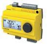
Single-room, heating and air-conditioning controllers | flexotron controllers for ventilation and air-conditioning
Features
• Five different control models for each device, for temperature, pressure, CO2, supply air cascade, heating
• Easy to operate with large, illuminated LCD and rotary knob
• Fast commissioning due to simple operating concept
• Weekly programme (depending on variant)
• External setpoint
Technical data
Power supply
RDT 405
RDT 410
Parameters
Power supply
Power consumption
Power consumption
24 V~, ±15%, 50...60 Hz (RDT4**F201
230 V~, +10%/-15% 50…60 Hz (RDT4**F301)
4 VA, 2 W
7.5 VA, 5 W
Start-up current 16 A (2 ms) 24V~ devices 23 A (2 ms) 230 V~ devices
Control characteristics
P-band Xp
Integral action time
Setting and measuring ranges
RDT 405
RDT 410
P/PI
0...99 K
0...990 s
Measuring range, temperature-20...60, 20…100, 60…140°C
Measuring range, temperature5…80, -30…50°C
Input for external setpoint
Air humidity
Ambient conditions
0…40°C
0...100% rh
Air humidity 0...100% rh
CO2
Ambient temperature
Ambient humidity
Inputs/outputs
10...9900 ppm for 100% signal
0...50 °C
5...95% rh, no condensation
Storage and transport temperature–20...70 °C
Universal inputs
Digital inputs
Analogue inputs
Analogue outputs
Digital outputs
Ni1000 (DIN 43760)
Potential-free contacts
Ni1000 (DIN 43760) for temperature, setpoint
0...10 V, 2 mA, protected against short circuit
RDT410F201: Triac
2 × 24 V~, 0.3 A 1 × 230 V~, 5 A
RDT410F301: Triac
2 × 24 V~, 0.16 A 1 × 230 V~, 5 A
RDT4**F*01
Construction
Dimensions W × H × D 123 × 99 × 64 mm
Screw terminals For electrical cables of up to 1.5 mm²
Fitting
Top-hat rail, wall, panel
Housing material PC+ABS

Standards and directives
Type of protection1) IP20 (EN 60529)
Protection class II (RDT410F301 only)
CE conformity according toEMC Directive 2014/30/EUEN 61000-6-1, EN61000-6-3
Overview of types
Type
A Week time-switch: only RDT410F*01 (number of switching commands: 8)
Accessories
Type Description
XYE460F001flexotron400 demo case
0460240001flexotron400/800 pluggable terminal strips
0460240010Cabinet fitting kit for flexotron400
EGT388F102External setpoint adjuster, room operating unit with potentiometer and temperature sensor, recessed
EGT333F102External setpoint adjuster, room operating unit with potentiometer and temperature sensor, surfacemounted
SAUTER VAV controllers enable the air volume to be regulated in accordance with demand in order to optimise energy consumption in ventilation systems. They are used in laboratories, clean rooms, hospital wards and operating theatres. In combination with additional sensors and monitoring facilities, they ensure that fume cupboards are regulated in accordance with the relevant standards.
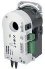
Features
• Supply and return air control for individual rooms such as offices, conference rooms and hotel rooms, in conjunction with a VAV box or a damper and flow probe
• Pressure control in supply and return air ducts for low-noise, energy-efficient air distribution
• Static measurement of differential pressure with MEMS sensor
• Can be used for measuring in areas with dirty or contaminated return air
• Low energy consumption and long serviceable life thanks to low-wear stepping motor
• Electromechanical, torque-based switch-off for safe operation
• Extremely simple installation due to self-centring shaft adapter
• Disengageable gear unit for manual adjustment and positioning of damper
• Integrated second control loop for the following applications1):
• Duct pressure and zone control
• Room climate regulation
• 2 x RS-485 bus interface on RJ12 and connection terminal
• Up to 31 subscribers in a segment with SLC (SAUTER Local Communication) protocol
• Communication within network via BACnet MS/TP
• Input and output signals for integrating:
• Setpoints and actual values
• Power outputs for reheaters and recoolers
• EY-RU 3** digital room operating units
• Analogue output
• Easy programming of the following applications using the SAUTER CASE VAV software2):
• Volume flow control
• Room pressure control
• Duct pressure control
• Adjustable end values of the differential pressure measuring range3)
• 100...300 Pa
• Efficient control algorithm for fast control loops
• Priority control via switching contacts
• Zero point can be calibrated
Technical data
Power supply
Power consumption at nominal voltage
50/60 Hz (~/=)
Power supply4)
Rated power during continuous operation5)
24 V~, +/-20%, 50...60 Hz
24 V=, -10%/+20%
4.7 VA/2.5 W
Power consumption when idle6) 1.5 VA/0.7 W
1) Application support depending on hardware and software version in CASE VAV manual D100316836 (German), D100316957 (English), D100316878 (French)
2) Application support depending on hardware and software version in CASE VAV manual D100316836 (German), D100316957 (English), D100316878 (French)
3) Available measuring ranges depending on hardware/type
4) 24 V=: Analogue inputs that are not connected are rated 0 V. The nominal torque is achieved within the specified tolerances.
5) Power specified without operating units FCCP 200, EY-RU 3*

6) Holding torque ASV205*: 4 Nm ASV215*: 8 Nm
Parameters
Integrated damper actuator Angle of rotation7) 90°
∆p sensor
Ambient conditions
Inputs/outputs
Interfaces and communication
Construction
Standards and directives
Admissible dimensions of damper shaftØ 8...16 mm, □ 6.5...12.7 mm
Admissible damper shaft (hardness)Max. 300 HV
Surge-voltage resistance
500 V (EN 60730)
Operating noise < 35 dB (A)
Measuring range ∆p (gain = 1)8) 0...500 Pa
Linearity error 2% (at 25 °C)
Time constant 0.2 s
Influence of position9) < 1 Pa
Reproducibility 0.2% FS
Zero point stability 0.2% for 1 year
Admissible positive pressure±12.5 kPa
Admissible operating pressure pstat 10) ±7 kPa
Low-pressure connections11) Ø i = 3.5...6 mm
Operating temperature 0...55 °C
Storage and transport temperature–20...55 °C
Air humidity < 85% rh, no condensation
Analogue inputs 0...10 V (Ri = 100 kΩ)
Analogue outputs 0...10 V, load > 10 kΩ
Digital inputs12) Closed 1 V=, 1 mA, open > 2 V=
Digital output 0.3 A at 24 V ~/=
Resistive input 0 to 50 °C
Ni1000 (DIN 43760), NTC10k (10k3A1), Pt1000 (EN 60751)
Resolution
0.3 °C (Ni1000/Pt1000), 0.1 °C (NTC)
Measuring difference +/- 0.6 °C
PWM
0.3 A at 24 V ~/=
Period duration 1 s....15 minutes 0...100%
RS-485 not electrically isolated115 kBaud
Communication protocols SAUTER Local Communication (SLC), BACnet MS/TP, ¼ load
Access method Master/slave
Topology Line
Number of participants13) 31 (32) with SLC
Bus termination 120 Ω (both ends)
Weight
Fitting
Type of protection
0.8 kg
Self-centring spindle adapter
IP00, IP30 (EN 60529) (with protection set)
Protection class III (EN 60730)
7) Maximum rotation angle 102° (without end stop)
8) Available measuring ranges depending on hardware/type
9) Zero adjustment recommended during commissioning
10) Short-term overload; zero adjustment of sensor is recommended
11) Recommended hardness of tubing < 40 Sha (e.g. silicone)
12) Digital inputs for external potential-free contacts (gold-plated recommended)
13) One participant is always also the parametering tool, hence the maximum number of 31 connectible devices Single-room,
Single-room, heating and air-conditioning controllers | VAV compact controllers
Conformity Machine directive 2006/42/EC, appendix II 1.B
EMC Directive 2014/30/EUEN 61000-6-1, EN 61000-6-3, EN 61000-6-4, EN 61000-6-2
Overview of types
Type Measuring range ∆pRunning time for 90°Rotational torqueHolding torque
ASV205BF132E0...300 Pa 30, 45, 60, 75, 90, 105 s 5 Nm 4 Nm
ASV215BF132E0...300 Pa 60, 75, 90, 105 s10 Nm 8
A For a running time of 105 s and an ambient temperature of ≥ 55 °C, the specified torque is reduced by 0.5 Nm.
A Current-free holding torque by means of interlocking in gear unit.
Accessories
Type Description
0372301001Spindle adaptor for squared end hollow profile (x 15 mm), pack of 10 pcs.
XAFP100F001Flow probe to measure the air volume in ventilation ducts
0300360001USB-RS-485 converter
0297867001Reference pressure container
0430360100IP30 protection set
0430360200Replacement LP connector
0372129001Torsion protection
Features
• Controlling the return air in fume cupboards and controlling the supply and return air in laboratories, clean rooms, hospital wards and operating theatres using a VAV box or a damper and flow probe
• Static measurement of differential pressure based on the capacitive method of measurement
• Zero point can be calibrated using software
• Adjustable end values of the differential pressure measuring range1)
• 50...150 Pa
• 100...300 Pa
• Can be used for measuring in areas with dirty or contaminated return air
• Brushless DC motor guarantees minimum energy consumption and a long service life
• Electromechanical, torque-based switch-off for safe operation
• Extremely simple installation due to self-centring shaft adapter
• Disengageable gear unit for manual adjustment and positioning of damper
• Easy programming of the following applications using SAUTER CASE Components:2)
• Volume flow control
• Room pressure control
• Duct pressure control
• Flow control for fume cupboards
• Efficient control algorithm for fast control loops
• Integrated second control loop for:3)
• Room-pressure control: can be ideally combined with EGP 100 with symmetrical measuring range
• Fume-cupboard control ideally combined with SVU 100, SGU 100 and FCCP 200
• 2 x RS-485 bus interface on RJ12 and connection terminal
• Up to 31 subscribers in a segment with SLC (SAUTER Local Communication) protocol
• Communication within network via BACnet MS/TP4)
• Integration of EY-RU 3** digital room operating units
• FCCP 200 display and alarm unit for fume-cupboard control or room monitoring
• Input and output signals for integrating:
• Setpoints and actual values
• Analogue output
• Priority control via switching contacts
Technical data
Power supply
Power consumption at nominal voltage
50/60 Hz (~/=) after 3 s running time
Rotational torque
Power supply5)
Rated power during continuous operation
Power consumption when idle6)
1) Available measuring ranges depending on hardware/type
10 Nm
24 V~, ±20%, 50...60 Hz
24 V=, -10%/+20%
Approx. 19 VA/10 W (10 Nm)
Approx. 20 VA/11 W with FCCP 200
Approx. 6 VA/2 W
2) Application support depending on hardware and software version in CASE VAV manual
3) Application support depending on hardware and software version in CASE VAV manual
4) Support of BACnet MS/TP interface
5) 24 V=: Analogue inputs that are not connected are rated 0 V. The nominal torque is achieved within the specified tolerances.
6) Holding torque approx. 5 Nm

Parameters
Rotational torque 10 Nm
Holding torque7) 2 Nm
Integrated damper actuator Angle of rotation8) 90°
Running time for 90°9) 3...15 s
Admissible dimensions of damper shaftØ 8...16 mm, □ 6.5...12.7 mm
Admissible damper shaft (hardness)Max. 300 HV
Surge-voltage resistance 500 V (EN 60730)
Operating noise < 49 dB (A) at 3 s ∆p sensor
Measuring range ∆p (gain = 1)
Pressure range, types D/E10) 0...150/300 Pa
Linearity error 2% FS
Time constant 0.1 s
Influence of position11) Typically ±1 Pa
Reproducibility 0.2% FS
Zero point stability 0.2% FS (at 20 °C)
Admissible positive pressure±10 kPa
Admissible operating pressure pstat 12) ±3 kPa
Low-pressure connections13) Ø i = 3.5...6 mm
Ambient conditions
Inputs/outputs
Interfaces and communication
Operating temperature 0...55 °C
Storage and transport temperature–20...55 °C
Air humidity < 85% rh, no condensation
Analogue inputs14) 0...10 V (Ri = 100 kΩ)
Digital inputs15) Closed 1 V=, 1 mA, open > 2 V=
Analogue outputs16) 0...10 V, load > 10 kΩ max. cable length 30 m max. adm. external voltage ±24 V
Digital output 0.3 A at 24 V ~/=
RS-485 not electrically isolated115 kBaud
Communication protocols17) SAUTER Local Communication (SLC), BACnet MS/TP, ¼ load
Access method Master/slave
Topology Line
Number of participants18) 31 (32) with SLC
Bus termination 120 Ω (both ends)
Construction
Standards and directives
Weight
0.8 kg
Fitting Self-centring spindle adapter
Type of protection
IP00, IP30 (EN 60529) (with protection set)
Protection class III (EN 60730)
7) Current-free holding torque by means of interlocking in gear unit
8) Maximum rotation angle 102° (without end stop)
9) Running time can be set via software
10) Available measuring ranges depending on hardware/type
11) Zero adjustment recommended during commissioning
12) Short-term overload; zero adjustment of sensor is recommended
13) Recommended hardness of tubing < 40 Sha (e.g. silicone)
14) Depending on the application, can be parameterised as an analogue input or output using SAUTER CASE Components
15) Digital inputs for external potential-free contacts (gold-plated recommended)
16) Depending on the application, can be parameterised as an analogue input or output using SAUTER CASE Components
17) Available protocols switched using software
18) One participant is always also the parametering tool, hence the maximum number of 31 connectible devices
Conformity
Machine directive 2006/42/EC, appendix II 1.B
EMC Directive 2014/30/EUEN 61000-6-1, EN 61000-6-3, EN 61000-6-4, EN 61000-6-2
Overview of types
Type Measuring range ∆p
ASV215BF152D0...150 Pa
ASV215BF152E0...300 Pa
Accessories
Type Description
0372301001Spindle adaptor for squared end hollow profile (x 15 mm), pack of 10 pcs.
XAFP100F001Flow probe to measure the air volume in ventilation ducts
0300360001USB-RS-485 converter
0297867001Reference pressure container
0430360100IP30 protection set
0430360200Replacement LP connector
0372129001Torsion protection
Single-room, heating and air-conditioning controllers | VAV compact controllers
FCCP200F010
International Design Award
Features
• Measured value display and indication of operating statuses for a range of ambient conditions such as pressure, temperature, relative humidity etc. in combination with an EY-RC 504/505 room automation station or an ASV 2*5 VAV compact controller
• Monitoring fume cupboards as per EN 14175-2 to check that they are functioning correctly and that the ventilation is operated to provide maximum safety for the laboratory staff
• Indication when the front sash is open > 500 mm
• Switching the fume cupboard lighting on and off
• Up to two function indicators for double-sided fume cupboards
• Indication of day/night change-over
• Audible alarm can be delayed or muted via configuration
• Demand-controlled regulation of fume cupboards as per EN 14175-6 in combination with the ASV 2*5 VAV compact controller
• Function indicator with visual and audible notification as per EN 14175-2
• Storage of all defined parameters with protection from power failure
• Interface for easy configuration of the connected VAV ASV 2*5
• Five freely configurable push-buttons1)
• Chemical-resistant glass surface
• Units that can be displayed: m/s, fps, l/s, m3/h, cfm, Pa, °C, °F, %rh, ppm
Technical data
Power supply
Parameters
Audible alarm
Optical alarm
Temperature sensor
Admissible ambient conditions
Power supply 5 V, ±10%
Power consumption 0.4 VA
Sound pressure level 80 dB (A)
Frequency 4 kHz
Alarm duration2) 60 s
Start-up delay Adjustable from 0 to 3200 s
Brightness EN 842, punctiform
Field of view > 120°
Measuring range of temperature sensor3) −5…50 °C
Operating temperature 5…45 °C
Storage temperature −20…80 °C
Humidity without condensation< 5…85% rh

Construction
Standards and directives
Dimensions W × H × D 169 × 36 × 12 mm
Protection class III (EN 60730)
Protection class (when installed)IP41 installed vertically
EMC Directive 2014/30/EUEN 61000-6-1, EN 61000-6-2, EN 61000-6-3, EN 61000-6-4
1) In combination with the EY-RC 504/505 room automation station and CASE Engine.
2) Can be set using software.
3) After it is installed, the temperature sensor must be calibrated using CASE Engine software during the commissioning.
Overview of types
Type Features
FCCP200F010Fume cupboard monitor and indicator
Accessories
Type Description
0300360001USB-RS-485 converter
0430600100USB-C RJ12 cable FCCP 200
Single-room, heating and air-conditioning controllers | VAV compact controllers
A high degree of flexibility for optimum results.
SAUTER valves and actuators each come in a few basic versions that cover all needs for reliable and long-lasting control elements. The valve and the actuator are perfectly matched to each another as a basis for optimum control quality.
The Smart Actuator allows autonomous control of heating, ventilation and air conditioning. Cloud-based applications and an app simplify commissioning as well as optimisation during operation.
322S:
VUP:
Multi-function valves
Overview of dynamic regulating valves
UVC 106: Dynamic flow control system with 6-way ball valve, eValveco262
UVC102MF065…100: Dynamic flow control system with 2-way valve and energy monitoring, eValveco
2-way regulating ball valve, PN 40
2-way regulating ball valve, PN 40
BKR: 3-way regulating ball valve, PN 40
BKRA: 3-way regulating ball valve, PN 40
VDL 010...050: 2-way regulating valve, PN 25, Valveco compact267 VDL 050…100: 2-way regulating valve, PN 16, Valveco flange272
2-way cut-off ball valve, PN 40
3-way changeover ball valve (L) with female thread, PN 40295
3-way changeover ball valve with female thread, PN 40
BKTA: 3-way changeover ball valve with male thread, PN 40
Damper and
ADM
ADM
ASF
ASF
SAUTER
Use SAUTER´s practical valve slide rule to specify the valve nominal diameter depending on the flow rate for liquids and saturated steam. You can order the slide rule at your sales partner or sales consultant.
A tried and tested tool for convenient valve and actuator specification, SAUTER provides installers and project engineers with its SAUTER VALVEDIM PC software. The tool comprises three function levels:
1. Valve and actuator specification
• using recommended values for a rough specification of the required versions and variables;
• based on the existing or stipulated installation values for the definitive specification of the required versions and variables.
2. Selection of the valve and the suitable actuator based on characteristics.
3. Direct transfer of the results to the project documentation.
VALVEDIM is available from your SAUTER subsidiary or as a download at https://www.sauter-controls.com/produkt/case-suite/

With the new CASE ValveDim mobile app, finding the right parts and the ideal valve/actuator combinations is impressively convenient and very efficient: Intuitive operation makes it easier to search for individual products and combine them.
Selected valve/actuator combinations can be stored in projects. Personal lists with valve/actuator combinations can be exported from the app as a project table in PDF format so that they can be shared with contacts. What’s more, CASE ValveDim can also be used offline.

Valve specification – manual calculation
Here you will find all the necessary information for the manual valve specification.
Variables, constants and formulas
Volume flow
Supplied heat per unit of time (heat flow)
Supplied heat per unit of time (heat flow)
Temperature difference
Specific thermal capacity of water
Density of water
Pressure difference across the valve
Calculated flow rate for the valve
Actual flow rate for the valve at nominal stroke, selected according to table or chart
Supposition:
The following are given:
To be found: V, kv
Approximate calculation of V
Assumption: Q to = Q from
Calculation of Kv
Determination of flow rate
Determination of k v from the diagram k vs = 16 m3/h
Example plotted: Given are the volume flow (3 m³/h) and a desired Δpv of 45 mbar, which results in a Kv value of 14.1 m³/h. The Kvs values entered are deliverable values. Selected: A valve with k vs = 16 m³/h, which results in a pressure difference Δpv of 35.2 mbar.
Features
• Smart Actuator as an intelligent IoT solution for autonomous control of heating and air-conditioning applications in smart buildings
• Ready-made HVAC standard applications enable efficient installation and commissioning of small systems
• Applications are selected from the library via smartphone app and installed on the Smart Actuator
• BACnet, Bluetooth LE and WLAN interface for flexible system integration
• Commissioning, parameterisation and remote access to the system are conveniently carried out via a smartphone app
• As an IoT device, the cloud connection for remote access takes place via MQTT using TLS encryption
• Extensive diagnostic data from the actuator enables predictive maintenance of installations
• Enables creation of Smart Actuator networks with distributed intelligence
• Optionally, the Smart Actuator can be used flexibly in BA networks due to free programmability via CASE Suite
• Real-time clock for calendar functions and time programmes
• Two universal I/Os for connecting external sensors and actuators
• Direct connection of a room operating unit
• Flexibly expandable with up to two Smart Actuator SAIO 100 I/O modules for comprehensive control tasks
• Pre-assembled cables, with colour- and mechanically-coded connectors, allow fast and error-free wiring
• Fitting without tools using a bayonet ring made of glass-fibre reinforced plastic
• BLDC motor technology enables extensive diagnostic functions
• Intelligent angle of rotation adaptation and detection incl. feedback signal
• Electronic, torque-dependent cut-off
• Gear unit can be disengaged for manual adjustment
• For operating the 2- and 3-way ball valves VKR, VKRA, BKR, BKRA, VKAI, VKAA, BKLI, BKTI and BKTA, as well as 6-way ball valve B2KL
Technical data
Power supply
Parameters
Ambient conditions
Power supply
Surge-voltage resistance
24 VAC, −10%/+20%, 50…60 Hz 24 VDC, −10%/+20%
500 V (EN 60730)
Rotational torque 8 Nm
Holding torque1) 8 Nm
Angle of rotation 90°
Response time 200 ms
Running time for 90° 35/60/120 sec.
Characteristic
Linear, (inverse) equal percentage, (inverse) quadratic, free characteristic
Operating noise (unloaded)< 30 dB (A)
Media temperature2)
Max. 100 °C
Ambient temperature −10…55 °C
Ambient humidity 5…85% rh, no condensation
Storage and transport temperature−20…70 °C
1) Holding torque energised and de-energised
2) At media temperatures < 5 °C or > 100 °C, appropriate accessory must be used
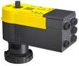


Smart Actuator app

Inputs/outputs
Type of inputs
Type of output
Function
Dynamic objects
Architecture
Interfaces, communication
RS-485 A connection4)
RS-485 B connection5)
Bluetooth
WLAN
Indicator/display
Construction
Standards, directives
Number of universal I/O 2
Analogue input U 0…10 V (Ri = 100 kΩ, ±0.05 V)
Analogue input I 4…20 mA (with ext. resistor 500 Ω or accessory 053060311**)
Digital input3)
Closed: ≤ 1 VDC, 1 mA
Open: ≥ 4 VDC
Ni1000 −20…100 °C (DIN 43760)
Pt1000 20…100 °C (IEC 751)
Resistor 200…3000 Ω
Analogue output U 0…10 V (±0.1 V)
BACnet data point objects Max. 100 (from firmware 1.1.0b58)
BACnet client links 16
Control
6 loops
Active COV Subscription 64
Time programmes 4 (Schedule)
Calendars 3 (Calendar)
Processor
ARM Cortex-M7 (528 MHz)
RAM (memory) 1024 kB
Flash 2 × 16 MB external, for data and system
Flash encryption 128-bit AES
Application data Via CASE Engine or mobile app
Operating system Zephyr
Cycle time 100 ms
Mobile app For commissioning and maintenance
Cloud Via MQTT to IoT hub
Real-time clock For time programmes and calendars
Communication protocol
BACnet MS/TP, ¼ load
Connection 2 × 3-pin connector, coded, daisy chain
Termination/Pull-Up/Pull-DownInternal, switchable via software
Communication protocol SLC master
Use 2 × I/O module, 1 × ecoUnit
Connection 5-pin connector, coded
Termination Internal, switchable via software
Version BLE 4.2
Range < 10 m
Radiation 4 mW
Standard IEEE 802.11 b/g
LED indicator 2 status LEDs (green/red and blue)
Fitting position
Connections at the bottom or side, not at the top
Dimensions W × H × D 168 × 137 × 74 mm
Weight 0.7 kg
Housing
Housing material
Type of protection
Lower section black, upper section yellow
Flame retardant plastic, PC/ABS
IP54 (EN 60529)
Protection class III (EN 60730-1)
3) Switching thresholds: 2.28 V (0 to 1) and 2.69 V (1 to 0) or 2.19 kΩ (0 to 1) and 2.69 kΩ (1 to 0)
4) Not electrically isolated
5) Not electrically isolated
Environment class 3K3 (IEC 60721)
CE/UKCA conformity6) RED 2014/53/EU (CE)
EN 60730-1:2011
EN 60730-2-14:1997 + A1:2001, A11:2005; A2:2008
EN 62479:2010
EN 301 489-1 V1.9.2
EN 61000-6-2:2005; AC:2005
EN 61000-6-3:2007 + A1:2011; AC 2012
EN 300 328 V2.2.2
RER-2017 (UKCA)
RoHS-D 2011/65/EU & 2015/863/EU (CE)
RoHS-2012 (UKCA)
See RED
EN IEC 63000
EN IEC 63000
Overview of types
Type Features Power consumption
AKM115SAF232Smart Actuator for ball valve, RS-485Max. 5 W / 10 VA (without peripherals)
A Power consumption: Without connected peripheral devices (room operating units, sensors, actuators or I/O modules)
Accessories
Type Description
SAIO100F020I/O module, 5 × UI/AO, 3 × relay 0510420001Adaptor required when temperature of the medium > 100 °C 0510240011Adaptor required when temperature of the medium < 5 °C 05393601000Dummy plug spare part set IP54
EY-PS031F011Power supply, 110…240 VAC/24 VDC, 1.25 A, 30 W, DIN rail mounting
EY-PS031F021Power supply, 110…240 VAC/24 VDC, 2.5 A, 60 W, DIN rail mounting
EY-PS031F041Power supply, 110…240 VAC/24 VDC, 4 A, 100 W, DIN rail mounting
A Order the device cables separately; see the section entitled “Accessories − power and connecting cables”
6) Explanation of abbreviations in the “Additional technical information” section of the product data sheet and in the appendix to SAUTER product catalogues Valves, control valves, dampers, actuators
Valves, control valves, dampers, actuators | Smart actuators
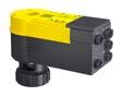
Features
• Smart Actuator as an intelligent IoT solution for autonomous control of heating and air-conditioning applications in smart buildings
• Ready-made HVAC standard applications enable efficient installation and commissioning of small systems
• Applications are selected from the library via smartphone app and installed on the Smart Actuator
• BACnet, Bluetooth LE and WLAN interface for flexible system integration
• Commissioning, parameterisation and remote access to the system are conveniently carried out via a smartphone app
• As an IoT device, the cloud connection for remote access takes place via MQTT using TLS encryption
• Extensive diagnostic data from the actuator enables predictive maintenance of installations
• Enables creation of Smart Actuator networks with distributed intelligence
• Optionally, the Smart Actuator can be used flexibly in BA networks due to free programmability via CASE Suite
• Real-time clock for calendar functions and time programmes
• Two universal I/Os for connecting external sensors and actuators
• Direct connection of a room operating unit
• Flexibly expandable with up to two Smart Actuator SAIO 100 I/O modules for comprehensive control tasks
• Pre-assembled cables, with colour- and mechanically-coded connectors, allow fast and error-free wiring
• Toolless assembly by means of automatic valve stem connection and brass cap nut
• BLDC motor technology enables extensive diagnostic functions
• Intelligent stroke adaptation and detection incl. feedback signal
• Electronic, torque-dependent cut-off
• Gear unit can be disengaged for manual adjustment
• For activation of 2-way and 3-way valves of the VUN/BUN, VUD/BUD and VUE/BUE series
Technical data
Power supply
Parameters
Power supply
Surge-voltage resistance
Actuating power
24 VAC, −10%/+20%, 50…60 Hz 24 VDC, −10%/+20%
500 V (EN 60730)
500 N
Actuator stroke 0...10 mm
Response time
Running time
Characteristic
Ambient conditions
Inputs/outputs

200 ms
35/60/120 sec.
Linear, (inverse) equal percentage, (inverse) quadratic, free characteristic
Operating noise (unloaded)< 30 dB (A)
Media temperature1) Max. 100 °C
Ambient temperature −10…55 °C
Ambient humidity 5…85% rh, no condensation
Storage and transport temperature−20…70 °C
Number of universal I/O 2
1) At media temperature > 100 °C, appropriate accessory must be used
Type of inputs
Analogue input U
0…10 V (Ri = 100 kΩ, ±0.05 V)
Analogue input I 4…20 mA (with ext. resistor 500 Ω or accessory 053060311**)
Digital input2)
Ni1000
Pt1000
Type of output
Function
Closed: ≤ 1 VDC, 1 mA
Open: ≥ 4 VDC
−20…100 °C (DIN 43760)
−20…100 °C (IEC 751)
Resistor 200…3000 Ω
Analogue output U 0…10 V (±0.1 V)
BACnet data point objects Max. 100 (from firmware 1.1.0b58)
BACnet client links 16
Control
Dynamic objects
Architecture
Interfaces, communication
RS-485 A connection3)
6 loops
Active COV Subscription 64
Time programmes
4 (Schedule)
Calendars 3 (Calendar)
Processor
ARM Cortex-M7 (528 MHz)
RAM (memory) 1024 kB
Flash 2 × 16 MB external, for data and system
Flash encryption 128-bit AES
Application data Via CASE Engine or mobile app
Operating system Zephyr
Cycle time 100 ms
Mobile app For commissioning and maintenance
Cloud Via MQTT to IoT hub
Real-time clock For time programmes and calendars
Communication protocol
Connection
BACnet MS/TP, ¼ load
2 × 3-pin connector, coded, daisy chain
Termination/Pull-Up/Pull-DownInternal, switchable via software
RS-485 B connection4) Communication protocol SLC master
Use
2 × I/O module, 1 × ecoUnit Connection 5-pin connector, coded
Termination Internal, switchable via software
Bluetooth Version BLE 4.2
Range < 10 m
Radiation 4 mW
WLAN Standard IEEE 802.11 b/g
Indicator/display LED indicator 2 status LEDs (green/red, blue)
Construction
Standards, directives
Fitting position
Connections at the bottom or side, not at the top
Dimensions W × H × D 168 × 119 × 74 mm
Weight 0.7 kg
Housing
Housing material
Type of protection
Lower section black, upper section yellow
Flame retardant plastic, PC/ABS
IP54 (EN 60529)
Protection class III (EN 60730-1)
Environment class 3K3 (IEC 60721)
2) Switching thresholds: 2.28 V (0 to 1) and 2.69 V (1 to 0) or 2.19 kΩ (0 to 1) and 2.69 kΩ (1 to 0)
3) Not electrically isolated
4) Not electrically isolated
Valves, control valves, dampers, actuators | Smart actuators
CE/UKCA conformity5)
RED 2014/53/EU (CE)
EN 60730-1:2011
EN 60730-2-14:1997 + A1:2001, A11:2005; A2:2008
EN 62479:2010
EN 301 489-1 V1.9.2
EN 61000-6-2:2005; AC:2005
EN 61000-6-3:2007 + A1:2011; AC 2012
EN 300 328 V2.2.2
RER-2017 (UKCA)
RoHS-D 2011/65/EU & 2015/863/EU (CE)
RoHS-2012 (UKCA)
See RED
EN IEC 63000
EN IEC 63000
Overview of types
Type Features Power consumption
AVM115SAF232Smart Actuator for globe valves, RS-485, BACnet MS/TP
Max. 5 W / 10 VA (without peripherals)
A Power consumption: Without connected peripheral devices (room operating units, sensors, actuators or I/O modules)
Accessories
Type Description
SAIO100F020I/O module, 5 × UI/AO, 3 × relay
0372249001Temperature adapter for AVM 321(S), required when temperature of the medium > 100...130 °C (recommended for temperatures < 10 °C) DN 15...50 0372273001Adapter for Siemens valve VVG/VXG 44, 48 05393601000Dummy plug spare part set IP54
EY-PS031F011Power supply, 110…240 VAC/24 VDC, 1.25 A, 30 W, DIN rail mounting
EY-PS031F021Power supply, 110…240 VAC/24 VDC, 2.5 A, 60 W, DIN rail mounting
EY-PS031F041Power supply, 110…240 VAC/24 VDC, 4 A, 100 W, DIN rail mounting
A Order the device cables separately; see the section entitled “Accessories − power and connecting cables”
5) Explanation of abbreviations in the “Additional technical information” section of the product data sheet and in the appendix to SAUTER product catalogues
Features
• Smart Actuator as an intelligent IoT solution for autonomous control of heating and air-conditioning applications in smart buildings
• Ready-made HVAC standard applications enable efficient installation and commissioning of small systems
• Applications are selected from the library via smartphone app and installed on the Smart Actuator
• BACnet, Bluetooth LE and WLAN interface for flexible system integration
• Commissioning, parameterisation and remote access to the system are conveniently carried out via a smartphone app
• As an IoT device, the cloud connection for remote access takes place via MQTT using TLS encryption
• Extensive diagnostic data from the actuator enables predictive maintenance of installations
• Enables creation of Smart Actuator networks with distributed intelligence
• Optionally, the Smart Actuator can be used flexibly in BA networks due to free programmability via CASE Suite
• Real-time clock for calendar functions and time programmes
• Two universal I/Os for connecting external sensors and actuators
• Direct connection of a room operating unit
• Flexibly expandable with up to two Smart Actuator SAIO 100 I/O modules for comprehensive control tasks
• Pre-assembled cables, with colour- and mechanically-coded connectors, allow fast and error-free wiring
• Easy fitting using self-centring spindle adapters
• BLDC motor technology enables extensive diagnostic functions
• Intelligent angle of rotation adaptation and detection incl. feedback signal
• Electronic, torque-dependent cut-off
• Gear unit can be disengaged for manual adjustment
Technical data
Power supply
Parameters
Power supply
Surge-voltage resistance
24 VAC, −10%/+20%, 50…60 Hz
24 VDC, −10%/+20%
500 V (EN 60730)
Rotational torque 10 Nm
Holding torque1) 10 Nm
Angle of rotation Max. 95°
Admissible damper shaft Ø 8...16 mm, □ 6.5...12.5 mm
Admissible damper shaft (hardness)Max. 300 HV
Response time 200 ms
Running time for 90° 35/60/120 sec.
Characteristic
Ambient conditions
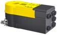
Inputs/outputs
Linear, (inverse) equal percentage, (inverse) quadratic, free characteristic
Operating noise (unloaded)< 30 dB (A)
Ambient temperature −10…55 °C
Ambient humidity 5…85% rh, no condensation
Storage and transport temperature−20…70 °C
Number of universal I/O 2
1) Holding torque energised and de-energised

Type of inputs
Analogue input U 0…10 V (Ri = 100 kΩ, ±0.05 V)
Analogue input I 4...20 mA (with ext. resistor 500 Ω or accessory 053060311**)
Digital input2)
Ni1000
Type of output
Function
Dynamic objects
Architecture
Interfaces, communication
RS-485 A connection3)
RS-485 B connection4)
Bluetooth
WLAN
Closed: ≤ 1 VDC, 1 mA
Open: ≥ 4 VDC
−20…100 °C (DIN 43760)
Pt1000 −20…100 °C (IEC 751)
Resistor 200…3000 Ω
Analogue output U 0…10 V (±0.1 V)
BACnet data point objects
Max. 100 (from firmware 1.1.0b58)
BACnet client links 16
Control 6 loops
Active COV Subscription 64
Time programmes 4 (Schedule)
Calendars 3 (Calendar)
Processor
ARM Cortex-M7 (528 MHz)
RAM (memory) 1024 kB
Flash 2 × 16 MB external, for data and system
Flash encryption 128-bit AES
Application data Via CASE Engine or mobile app
Operating system Zephyr
Cycle time 100 ms
Mobile app For commissioning and maintenance
Cloud Via MQTT to IoT hub
Real-time clock For time programmes and calendars
Communication protocol
BACnet MS/TP, ¼ load
Connection 2 × 3-pin connector, coded, daisy chain
Termination/Pull-Up/Pull-DownInternal, switchable via software
Communication protocol SLC master
Use 2 × I/O module, 1 × ecoUnit
Connection 5-pin connector, coded
Termination Internal, switchable via software
Version BLE 4.2
Range < 10 m
Radiation 4 mW
Standard IEEE 802.11 b/g
Indicator/display LED indicator 2 status LEDs (green/red, blue)
Construction
Standards, directives
Fitting position
Connections at the bottom or side, not at the top
Dimensions W × H × D 168 × 62 × 74 mm
Weight 0.7 kg
Housing
Housing material
Type of protection
Lower section black, upper section yellow
Flame retardant plastic, PC/ABS
IP54 (EN 60529)
Protection class III (EN 60730-1)
Environment class 3K3 (IEC 60721)
2) Switching thresholds: 2.28 V (0 to 1) and 2.69 V (1 to 0) or 2.19 kΩ (0 to 1) and 2.69 kΩ (1 to 0)
3) Not electrically isolated
4) Not electrically isolated
CE/UKCA conformity5)
RED 2014/53/EU (CE)
EN 60730-1:2011
EN 60730-2-14:1997 + A1:2001, A11:2005; A2:2008
EN 62479:2010
EN 301 489-1 V1.9.2
EN 61000-6-2:2005; AC:2005
EN 61000-6-3:2007 + A1:2011; AC 2012
EN 300 328 V2.2.2
RER-2017 (UKCA)
RoHS-D 2011/65/EU & 2015/863/EU (CE)
RoHS-2012 (UKCA)
See RED
EN IEC 63000
EN IEC 63000
Overview of types
Type Features Power consumption
ASM115SAF232Smart Actuator for dampers, RS-485, BACnet MS/TP
Max. 5 W / 10 VA (without peripherals)
A Power consumption: Without connected peripheral devices (room operating units, sensors, actuators or I/O modules)
Accessories
Type Description
SAIO100F020I/O module, 5 × UI/AO, 3 × relay
0361977002Assembly materials for M3R, M4R, MH32R/F, MH42R with ASM 105, 115 0372300001Torsion protection, long (230 mm) 05393601000Dummy plug spare part set IP54 0372301001Spindle adaptor for squared end hollow profile (x 15 mm), pack of 10 pcs. 0372320001Hexagon key as visualisation for position indicator
EY-PS031F011Power supply, 110…240 VAC/24 VDC, 1.25 A, 30 W, DIN rail mounting
EY-PS031F021Power supply, 110…240 VAC/24 VDC, 2.5 A, 60 W, DIN rail mounting
EY-PS031F041Power supply, 110…240 VAC/24 VDC, 4 A, 100 W, DIN rail mounting
A Order the device cables separately; see the section entitled “Accessories − power and connecting cables”
5) Explanation of abbreviations in the “Additional technical information” section of the product data sheet and in the appendix to SAUTER product catalogues
Features
• Extends the inputs and outputs of the smart actuator for extensive control tasks
• Connection of sensors or actuators via five integrated universal inputs and outputs
• Three changeover relays for fan or pump control
• Connection to the smart actuator via plug-in I/O module cable (SLC)
• Direct connection of a room operating unit
• Housing according to IP54 enables use without cabinet
• Separate 24 V power supply for sensors and actuators with total power requirement up to 1 A
Technical data
Power supply
Ambient conditions
Inputs/outputs
Type of inputs
Type of output
Interfaces, communication
RS-485 connection
Power supply
24 VAC/DC (via smart actuator) 24 VAC/DC for terminals T4...T7 (via separate power supply)
Power consumption 1.2 VA at 24 VDC (without sensors and actuators)
Ambient temperature
−10…55 °C
Ambient humidity 5...95% rh, no condensation
Storage and transport temperature−20…70 °C
Number of universal I/O 5 (+1 from smart actuator)
Number of relays 3
Rating 10 A (resistive) 5 A (inductive)
Type Change-over
Analogue input U 0…10 V (Ri = 100 kΩ, ±0.05 V)
Analogue input I 4...20 mA (with ext. resistor 500 Ω)
Digital input
Closed: 1 VDC, 1 mA
Open: > 2 VDC
Ni1000 −20…100 °C (DIN 43760)
Pt1000 −20…100 °C (IEC 751)
Resistor 100…2500 Ω (±25 Ω)
Analogue output U 0…10 V (±0.4 V)
Communication protocol SLC slave
Use 1 × I/O module, 1 × ecoUnit
Connection 5-pin connector, coded
Termination
Internal, DIP switch
Indicator/display LED indicator 1 status LED (green, red)
Construction
Fitting
Standards, directives

On DIN rail 35 × 7.5/15 (EN 60715) or on supplied rail
Dimensions W × H × D 200 × 107 × 55 mm
Weight 0.5 kg
Housing
Housing material
Type of protection
Lower section black, upper section yellow
Flame retardant plastic, PC/ABS
IP54 (EN 60529)
Protection class III (EN 60730-1)
Environment class
3K3 (IEC 60721)
Valves, control valves, dampers, actuators | Smart actuators
CE conformity according toEMC Directive 2014/30/EUEN 61000-6-1, EN 61000-6-3, EN 61000-6-4
Low-Voltage Directive 2014/35/EUEN 60730-1, EN 60730-2-14
Overview of types
Type Features
SAIO100F020I/O module for smart actuator, 6 pcs. UI/AO, 3 pcs. relay
Power consumption
Max. 1.7 W / 3.6 VA (without peripherals)
Accessories
Type Description
05393601000Dummy plug spare part set IP54
A For power cables or connecting cables (053060*****), see order code in PDS 53.950

Features
• For connection to the power supply, to cable temperature sensors, and for connecting the actuators
• Pre-assembled cables in various lengths from 0.5 to 30 metres
• Robust XLPE sheathed cables1) With mechanically and colour-coded connectors
• Silicone- and halogen-free
• Can also be laid under plaster, in and on masonry and non-reinforced concrete2)
Technical data
Parameters
Ambient conditions
Construction
Bending radius
Ambient temperature
Material
Min. 10 × external diameter for fixed installation
Max. +70 °C
Silicone- and halogen-free according to EN 60754-1/2
Flame retardant according to EN 60332-1-2
Version Conductor stranded bare copper wires, open ends ultrasonically welded
Colour
Standards, directives
CE/UKCA conformity according toRoHS-D 2011/65/EU & 2015/863/EU (CE)
RoHS-2012 (UKCA)
Black (plug and sheath)
EN IEC 63000
EN IEC 63000 Overview

0530602002024 V power supply, open cable end
0530602020124 V power supply, Y-connector
05306031001I/O signals, open cable end, 3-core
05306031005I/O signals, open cable end, 3-core
05306031010I/O signals, open cable end, 3-core
05306031020I/O signals, open cable end, 3-core
05306031030I/O signals, open cable end, 3-core 30.0 m3-pin
05306031105I/O signals (I), open cable end, 3-core 5.0 m3-pin
05306032001I/O signals, cable temperature sensor Ni1000 (-35...100 °C), ready to plug in 1.0 m 3-pin
05306032005I/O signals, cable temperature sensor Ni1000 (-35...100 °C), ready to plug in 5.0 m 3-pin
05306032010I/O signals, cable temperature sensor Ni1000 (-35...100 °C), ready to plug in 10.0 m 3-pin
05306032020I/O signals, cable temperature sensor Ni1000 (-35...100 °C), ready to plug in 20.0 m 3-pin
1) XLPE: Cross-linked polyethylene 2) National regulations must be observed
Type
Cable type
05306032101I/O signals, cable temperature sensor Pt1000 (-50...180 °C), ready to plug in 1.0 m 3-pin 05306032105I/O signals, cable temperature sensor Pt1000 (-50...180 °C), ready to plug in
05306034000RS-485, daisy chain, open cable end, 3-core
05306034001RS-485, daisy chain, open cable end, 3-core
05306034005RS-485, daisy chain, open cable end, 3-core
05306034010RS-485, daisy chain, open cable end, 3-core
05306034020RS-485, daisy chain, open cable end, 3-core
05306034030RS-485, daisy chain, open cable end, 3-core
05306034100RS-485, daisy chain, connection of two actuators, ready to plug in
3-pin
3-pin 05306034101RS-485, daisy chain, connection of two actuators, ready to plug in
3-pin 05306034105RS-485, daisy chain, connection of two actuators, ready to plug in
05306034110RS-485, daisy chain, connection of two actuators, ready to plug in
05306034120RS-485, daisy chain, connection of two actuators, ready to plug in
3-pin
3-pin
3-pin 05306034130RS-485, daisy chain, connection of two actuators, ready to plug in
3-pin
05306051000I/O signals, open cable end, 3-core 0.5 m5-pin 05306051001I/O signals, open cable end, 3-core 1.0 m5-pin 05306051005I/O signals, open cable end, 3-core 5.0 m5-pin 05306051010I/O signals, open cable end, 3-core 10.0 m5-pin 05306051020I/O signals, open cable end, 3-core
05306051030I/O signals, open cable end, 3-core
05306053000I/O signals, connection of actuator to I/O module SAIO100, ready to plug in 0.5 m 5-pin 05306053001I/O signals, connection of actuator to I/O module SAIO100, ready to plug in 1.0 m 5-pin
05306053005I/O signals, connection of actuator to I/O module SAIO100, ready to plug in
5-pin
05306053010I/O signals, connection of actuator to I/O module SAIO100, ready to plug in 10.0 m 5-pin
05306053020I/O signals, connection of actuator to I/O module SAIO100, ready to plug in
5-pin
05306053030I/O signals, connection of actuator to I/O module SAIO100, ready to plug in 30.0 m 5-pin
05306053500SLC connection, open cable end, 5-core 0.5 m5-pin 05306053501SLC connection, open cable end, 5-core 1.0 m5-pin 05306053505SLC connection, open cable end, 5-core 5.0 m5-pin 05306053510SLC connection, open cable end, 5-core 10.0 m5-pin 05306053520SLC connection, open cable end, 5-core 20.0 m5-pin 05306053530SLC connection, open cable end, 5-core 30.0 m5-pin
A Other models and lengths on request. For order numbers, see order code below
Example
Order no.Designation
05306020000Power cable, 2-pin, 24 V power supply, open cable end, 2-core, 0.5 m
Order code
(1) Product type(2) Model(3) Cable length 053060……200……00
A Not all theoretically possible combinations can be ordered
3) Conductor cross-section depends on cable type and cable length Valves, control valves, dampers, actuators | Smart actuators
(1) Product type
Order no.Type
053060…Power and connecting cables for Smart Actuator
(2) Model
Order no.Plug Function and connection
…200…2-pin24 V power supply, open cable end
…201…2-pin24 V power supply, daisy chain
…202…2-pin24 V power supply, Y-connector
…310…3-pin I/O signals, 3-core open cable end
…510…5-pin
…311…3-pinI/O signals for current measurement with integrated 500 Ω resistor, 3-core open cable end
…320…3-pinI/O signals, cable temperature sensor Ni1000 (-35...100 °C), ready to plug in
…321…3-pinI/O signals, cable temperature sensor Pt1000 (-50...180 °C), ready to plug in
…340…3-pinRS-485, daisy chain, 3-core open cable end
…341…3-pinRS-485, daisy chain, connection of two actuators, ready to plug in
…530…5-pinI/O signals, connection of actuator with I/O module SAIO100, ready to plug in
…535…5-pinSLC connection, 5-core open cable end
(3) Cable length
Order no.Length (m)
Conductor cross-section (mm²)3)
…00 0.50.5/0.75
…01 1.00.5/0.75
…05 5.00.5/0.75
…10 10.00.75
…20 20.00.75
…30 30.00.75
In combination with thermal actuators, unit valves are used to control radiators, air reheaters and recoolers as well as fan coil units.
Overview of unit valves
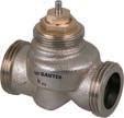
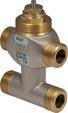
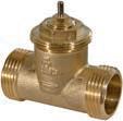
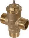
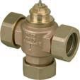
Application
Single-room control
Chilled ceiling, underfloor heating
Version
2-way
Combination options with actuator
AXM 217(S) AXT 301
AXS 315S
AXF 217S
AXM 217(S) AXT 301
AXS 315S
AXF 217S
AXM 217(S) AXT 301
AXS 315S
AXF 217S
AXM 217(S) AXT 301
AXS 315S
AXF 217S
AXM 217(S) AXT 301
AXS 315S
AXF 217S
Features
• Regulation of heating zones, air secondary-treatment units and fan coil units in combination with AXF 217S, AXM 217(S), AXT 301 or AXS 315S actuators for unit valves
• Flat-sealing standard version or version with clamping ring screw fitting for pipe Ø 15 mm with DN 10
• Valve with male thread as per DIN EN ISO 228-1, class B
• Stuffing box can be replaced under system pressure
• Control passage A–AB is closed when the spindle is moved in
• Closes against the pressure
• Valve body made of nickel-plated cast brass for DN 10 and gunmetal for DN 15 and DN 20
• Plug with EPDM soft seal
• Stainless-steel spindle
• Stuffing box with double O-ring seal
Technical data
Parameters


ValveDim app
Ambient conditions

Standards, directives
Nominal pressure PN 16
Operating pressure Max. 16 bar (up to 120 °C)
Operating temperature 2…120 °C
Valve characteristic
Equal percentage
Valve stroke1) 4 mm
Leakage rate 0.002% of Kvs value
Operating temperature at valveMax. 100 °C in combination with AXF 217S, AXM 217(S), AXS 315S and AXT 301
Pressure and temperature dataEN 764, EN 1333
Flow parameter
PED 2014/68/EU
VDI/VDE 2173
Fluid group II, No CE label (article 4.3)
Overview of types
Type Nominal diameter Kvs valueConnection Weight
VUL010F340DN 100.16 m³/hG½" B 0.19 kg
VUL010F330DN 100.4 m³/hG½" B 0.18 kg
VUL010F320DN 100.63 m³/hG½" B 0.18 kg
VUL010F310DN 101 m³/hG½" B 0.18 kg
VUL010F300DN 101.6 m³/hG½" B 0.18 kg
VUL015F310DN 152.5 m³/hG¾" B 0.28 kg
VUL015F300DN 153.5 m³/hG¾" B 0.28 kg
VUL020F300DN 204.5 m³/hG1" B 0.33 kg
VUL010F630DN 100.4 m³/hClamping ring version Ø15 mm0.18 kg
VUL010F620DN 100.63 m³/hClamping ring version Ø15 mm0.18 kg
VUL010F610DN 101 m³/hClamping ring version Ø15 mm0.18 kg
VUL010F600DN 101.6 m³/hClamping ring version Ø15 mm0.18 kg 1) The valve stroke is limited by the actuator
Accessories
Type Description
0378133010Threaded sleeve, R⅜, flat-sealing, with cap nut and flat seal, G½ - R⅜
0378133015Threaded sleeve, R½, flat-sealing, with cap nut and flat seal, G¾ - R½
0378133020Threaded sleeve, R¾, flat-sealing, with cap nut and flat seal, G1 - R¾
0378134010Solder nipple, Ø 12, flat-sealing, with cap nut and flat seal, G½ 0378134015Solder nipple, Ø 15, flat-sealing, with cap nut and flat seal, G¾
0378134020Solder nipple, Ø 22, flat-sealing, with cap nut and flat seal, G1
0378135010Clamping ring screw fitting for pipe Ø 15 mm, DN 10 0378145015Clamping ring screw fitting for pipe Ø 15 mm, DN 15, flat-sealing, G¾ 0378145020Clamping ring screw fitting for pipe Ø 22 mm, DN 20, flat-sealing, G1 0378128001Stuffing box for VUL valves, can be replaced under pressure
Combination of VUL with electric actuators
/ Warranty:The technical data and pressure differences indicated here are applicable only in combination with SAUTER valve actuators. Any warranty will be invalidated if used with valve actuators from other manufacturers.
/ Definitionof∆ps:Maximum admissible pressure drop in the event of a malfunction (pipe break after the valve) at which the actuator reliably closes the valve.
/ Definitionof∆pmax:Maximum admissible pressure drop in control mode at which the actuator reliably opens and closes the valve.
Pressure differences with motorised actuators
ActuatorAXF217SF404
Control signal 0/2…10 V, 0…5 V, 5…10 V, 0/4…20 mA
Cannot be used to close with the pressure Valves,
Cannot be used to close with the pressure
Pressure differences with thermal actuators
Cannot be used to close with the pressure Valves, control valves, dampers, actuators | Unit valves and actuators for unit valves
Pressure differences with thermal continuous actuators
ActuatorAXS315SF102
AXS315SF202
Page 166 166
Voltage24 VAC/DC 24 VAC/DC
Control signal0…10 V 0…10 V
Running time30 s/mm 30 s/mm
Closes against the pressure
VUL010F340 VUL010F330
Valves, control valves, dampers, actuators | Unit valves and actuators for unit valves
Features
• Ideally suited for AXF 217S, AXM 217(S), AXS 315S and AXT 301 unit valve actuators
• Flat-sealing standard version or version with clamping ring screw fitting for pipe Ø 15 mm with DN 10
• Valve with male thread as per DIN EN ISO 228-1, class B
• Special model for fan coil units with cast-on bypass T-piece
• Control passage A–AB is closed when the spindle is moved in
• Can be used as a control valve and, thanks to its tight-sealing third passage, as a distribution valve
• Valve body made of nickel-plated cast brass
• Plug with EPDM soft seal for control passage and mixing passage
• Stainless-steel spindle
• Stuffing box with double O-ring seal
Technical data
Parameters
Ambient conditions
Standards, directives
Nominal pressure
Operating pressure
Operating temperature
PN 16
Max. 16 bar (up to 120 °C)
2…120 °C
Control passage valve characteristicEqual percentage
Mixing passage valve characteristicLinear
Valve stroke 3.7 mm
Leakage rate of control passage A–AB0.0001% of kvs value
Leakage rate of mixing passage B–ABApprox. 0.1% of Kvs value
Operating temperature at valveMax. 100 °C in combination with AXF 217S, AXM 217(S), AXS 315S and AXT 301
Pressure and temperature dataEN 764, EN 1333
Flow parameter
PED 2014/68/EU
Overview of types
/ The BUL 3-way valve must not be used as a 2-way valve / Kvs value: The Kvs value of the mixing passage (B–AB) is approx. 30% lower
Type
diameter Kvs valueConnection
BUL010F330DN 100.4 m³/hG½" B
BUL010F320DN 100.63 m³/hG½" B
BUL010F310DN 101 m³/hG½" B
BUL010F300DN 101.6 m³/hG½" B
VDI/VDE 2173
Fluid group II, No CE label (article 4.3)
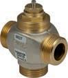
Control valve
Distribution valve
kg
kg
kg
BUL015F310DN 152.5 m³/hG¾" B 0.33
BUL010F430DN 100.4 m³/hG½" B
BUL010F420DN 100.63 m³/hG½" B
BUL010F410DN 101 m³/hG½" B
BUL010F400DN 101.6 m³/hG½" B
BUL015F410DN 152.5 m³/hG¾" B
kg
BUL015F400DN 154 m³/hG¾" B 0.42 kg

Type Nominal diameter Kvs valueConnection Weight
BUL020F400DN 205 m³/hG1" B 0.50 kg
BUL010F630DN 100.4 m³/hClamping ring version Ø 15 mm0.38 kg
BUL010F620DN 100.63 m³/hClamping ring version Ø 15 mm0.38 kg
BUL010F610DN 101 m³/hClamping ring version Ø 15 mm0.38 kg
BUL010F600DN 101.6 m³/hClamping ring 0.38 kg
A BUL0**F4**: Version with bypass T-piece
Accessories
Type Description
0378133010Threaded sleeve, R⅜, flat-sealing, with cap nut and flat seal, G½ - R⅜
0378133015Threaded sleeve, R½, flat-sealing, with cap nut and flat seal, G¾ - R½
0378133020Threaded sleeve, R¾, flat-sealing, with cap nut and flat seal, G1 - R¾
0378134010Solder nipple, Ø 12, flat-sealing, with cap nut and flat seal, G½
0378134015Solder nipple, Ø 15, flat-sealing, with cap nut and flat seal, G¾
0378134020Solder nipple, Ø 22, flat-sealing, with cap nut and flat seal, G1
0378135010Clamping ring screw fitting for pipe Ø 15 mm, DN 10
0378145015Clamping ring screw fitting for pipe Ø 15 mm, DN 15, flat-sealing, G¾
0378145020Clamping ring screw fitting for pipe Ø 22 mm, DN 20, flat-sealing, G1
0378126001Stuffing box for BUL valves
0378126002Stuffing box for BUL valves as of manufacturing date 1501
Combination of BUL with electric actuators
/ Warranty:The technical data and pressure differences indicated here are applicable only in combination with SAUTER valve actuators. Any warranty will be invalidated if used with valve actuators from other manufacturers.
/ Definitionof∆ps:Maximum admissible pressure drop in the event of a malfunction (pipe break after the valve) at which the actuator reliably closes the valve.
/ Definitionof∆pmax:Maximum admissible pressure drop in control mode at which the actuator reliably opens and closes the valve.
Pressure differences with motorised actuators
ActuatorAXF217SF404
AXF217SF405
AXM217SF402
AXM217SF404
Control signal
BUL010F330
BUL010F320
BUL010F310
BUL010F300
BUL010F430
BUL010F420
BUL010F410
BUL010F400
BUL010F630
BUL010F620
BUL010F610
BUL010F330
Pressure differences with thermal continuous actuators
ActuatorAXS315SF102
AXS315SF202
Page 166 166
Voltage24 VAC/DC
BUL010F330 BUL010F320 BUL010F310
BUL010F300 BUL010F430
BUL010F420 BUL010F410 BUL010F400 BUL010F630 BUL010F620 BUL010F610 BUL010F600
BUL010F330 BUL010F320 BUL010F310 BUL010F300 BUL010F430 BUL010F420
BUL010F410 BUL010F400 BUL010F630
BUL010F620 BUL010F610 BUL010F600
ActuatorAXS315SF102
AXS315SF202
Page 166 166
Features
• Regulation of fan coil units, air secondary-treatment units, heating zones and two-pipe systems with heat exchanger in combination with AXF 217S, AXM 217(S), AXS 315S and AXT 301 actuators for unit valves
• Flat-sealing standard version
• Adjustable Kvs value
• When the spindle is pushed in, the valve is closed
• Closes against the pressure
• Valve with male thread as per DIN EN ISO 228-1, class B
• Valve body made of cast brass
• Stainless-steel spindle
• Plug with EPDM soft seal
• Stuffing box with O-ring seal
• Water quality as per VDI 2035
Technical data
Parameters
Ambient conditions
Standards, directives
Nominal pressure PN 16
Operating pressure Max. 16 bar (up to 120 °C)
Operating temperature 2…120 °C
Valve characteristic Almost linear Leakage rate ≤ 0.0001% of Kvs value
Operating temperature at valveMax. 100 °C in combination with AXF 217S, AXM 217(S), AXS 315S and AXT 301
Pressure and temperature dataEN 764, EN 1333
Flow parameter EN 60534, page 3
PED 2014/68/EU Fluid group II, No CE label (article 4.3)
Overview of types Type
VUT010F210DN 100.2…1.0 m³/h3
VUT015F200DN 151.0…3.5 m³/h4
Accessories
Type Description
0378133010Threaded sleeve, R⅜, flat-sealing, with cap nut and flat seal, G½ - R⅜ 0378133015Threaded sleeve, R½, flat-sealing, with cap nut and flat seal, G¾ - R½
0378133020Threaded sleeve, R¾, flat-sealing, with cap nut and flat seal, G1 - R¾
0378134010Solder nipple, Ø 12, flat-sealing, with cap nut and flat seal, G½ 0378134015Solder nipple, Ø 15, flat-sealing, with cap nut and flat seal, G¾ 0378134020Solder nipple, Ø 22, flat-sealing, with cap nut and flat seal, G1

Combination of VUT with electric actuators
/ Warranty:The technical data and pressure differences indicated here are applicable only in combination with SAUTER valve actuators. Any warranty will be invalidated if used with valve actuators from other manufacturers.
/ Definitionof∆ps:Maximum admissible pressure drop in the event of a malfunction (pipe break after the valve) at which the actuator reliably closes the valve.
/ Definitionof∆pmax:Maximum admissible pressure drop in control mode at which the actuator reliably opens and closes the valve.
Pressure differences with motorised actuators
ActuatorAXF217SF404
AXF217SF405
AXM217SF402
AXM217SF404
Page 169
Control signal
Cannot be used to close with the pressure
Pressure differences with thermal actuators ActuatorAXT301F100
Pressure differences with thermal continuous actuators
ActuatorAXS315SF102
AXS315SF202 Page 166 166
Voltage24 VAC/DC
Valves, control valves, dampers, actuators | Unit valves and actuators for unit valves
ActuatorAXS315SF102
AXS315SF202 Page 166 166
Cannot be used to close with the pressure
Features
• Regulation of fan coil units, air secondary-treatment units, heating zones and two-pipe systems with heat exchanger in combination with AXF 217S, AXM 217(S), AXS 315S and AXT 301 actuators for unit valves
• Flat-sealing standard version
• Special model for fan coil units with cast-on bypass T-piece
• Control passage closed when spindle is pushed in
• Used as a control valve
• Valve with male thread as per DIN EN ISO 228-1, class B
• Valve body made of cast brass
• Stainless-steel spindle
• Plug with soft seal made of EPDM for control passage and mixing passage
• Stuffing box with O-ring seal
• Water quality as per VDI 2035
Technical data
Parameters
Ambient conditions
Standards, directives
Nominal pressure
Operating pressure
Operating temperature
PN 16
Max. 16 bar (up to 120 °C)
2…120 °C
Control passage valve characteristicAlmost linear
Mixing passage valve characteristicLinear (not reduced)
Leakage rate of control passage A–AB0.0001% of Kvs Leakage rate of mixing passage B–ABApprox. 0.1% of Kvs
Operating temperature at valveMax. 100 °C in combination with AXF 217S, AXM 217(S), AXS 315S and AXT 301
Pressure and temperature dataEN 764, EN 1333
Flow parameter VDI/VDE 2173 PED 2014/68/EU
Fluid group II, No CE label (article 4.3)
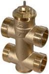
Overview of types
/ The BUT control valve must not be used as a through valve or diverting valve; the mixing passage is not reduced.

BUT0**F4**: Version with bypass T-piece
Accessories
Type Description
0378133010Threaded sleeve, R⅜, flat-sealing, with cap nut and flat seal, G½ - R⅜
0378133015Threaded sleeve, R½, flat-sealing, with cap nut and flat seal, G¾ - R½
0378133020Threaded sleeve, R¾, flat-sealing, with cap nut and flat seal, G1 - R¾
0378134010Solder nipple, Ø 12, flat-sealing, with cap nut and flat seal, G½
0378134015Solder nipple, Ø 15, flat-sealing, with cap nut and flat seal, G¾
0378134020Solder nipple, Ø 22, flat-sealing, with cap nut and flat seal, G1
0378145015Clamping ring screw fitting for pipe Ø 15 mm, DN 15, flat-sealing, G¾
0378145020Clamping ring screw fitting for pipe Ø 22 mm, DN 20, flat-sealing, G1
Combination of BUT with electric actuators
/ Warranty:The technical data and pressure differences indicated here are applicable only in combination with SAUTER valve actuators. Any warranty will be invalidated if used with valve actuators from other manufacturers.
/ Definitionof∆ps:Maximum admissible pressure drop in the event of a malfunction (pipe break after the valve) at which the actuator reliably closes the valve.
/ Definitionof∆pmax:Maximum admissible pressure drop in control mode at which the actuator reliably opens and closes the valve. Data for a static pressure of 6 bar.
/ Definitionofclose/offpressure:Max. admissible differential pressure when closing the valve. Calculation, see below.
Pressure differences with motorised actuators
ActuatorAXF217SF404
AXF217SF405
AXM217SF402
AXM217SF404
A Close/off pressure = ∆pmax + 0.1 bar
Pressure differences with thermal actuators
ActuatorAXT301F100
Page 163
Pressure differences with thermal continuous actuators
ActuatorAXS315SF102
AXS315SF202
Page 166 166
Voltage24 VAC/DC 24 VAC/DC
Control signal0…10 V 0…10 V
Running time30 s/mm
Cannot be used as distribution valve
A Close/off pressure = ∆pmax + 0.1 bar
Features
• Ideally suited as a control valve for AXF 217S, AXM 217(S), AXS 315S and AXT 301 unit valve actuators
• Valve with male thread as per DIN EN ISO 228-1, class A
• Control passage A–AB open when the spindle is moved in
• Used as a control valve
• Valve body made of gunmetal
• Plug with EPDM soft seal
• Stainless-steel spindle
• Stuffing box with double O-ring seal
• Version with cap nut and flat seal
Technical data
Parameters
Ambient conditions
Standards, directives
Nominal pressure PN 16
Operating pressure Max. 16 bar at 130 °C
Operating temperature 2…130 °C
Control passage valve characteristicLinear
Mixing passage valve characteristicComplementary, reduced
Valve stroke 2.9 mm
Control passage leakage rateApprox. 0.05% of Kvs value
Mixing passage leakage rateApprox. 0.2% of Kvs value
Operating temperature at valveMax. 100 °C in combination with AXF 217S, AXM 217(S), AXS 315S and AXT 301
Pressure and temperature dataEN 764, EN 1333
Flow parameter VDI/VDE 2173
PED 2014/68/EU
Overview of types
/ The BXL 3-way valve must not be used as a 2-way valve
Fluid group II, No CE label (article 4.3)
Accessories
Type Description
03618240253 threaded sleeves, R 1", flat-sealing
03618240403 threaded sleeves, R 5/4", flat-sealing
03618250283 solder nipple, Ø 28; flat-sealing, DN 25
03618250353 solder nipple, Ø 35; flat-sealing, DN 40
03618250423 solder nipple, Ø 42; flat-sealing, DN 40

Combination of BXL with electric actuators
/ Warranty:The technical data and pressure differences indicated here are applicable only in combination with SAUTER valve actuators. Any warranty will be invalidated if used with valve actuators from other manufacturers.
/ Definitionof∆pmax:Maximum admissible pressure drop in control mode at which the actuator reliably opens and closes the valve. Data for a static pressure of 6 bar.
Pressure differences with motorised actuators
ActuatorAXF217SF404
AXF217SF405
AXM217SF402
AXM217SF404
Page 169
Voltage24 VAC/DC
Control signal
0/2…10 V, 0…5 V, 5…10 V, 0/4…20 mA 2-/3-point 2-/3-point
Running time 8 s/mm
Cannot be used as distribution valve
Pressure differences with thermal actuators
ActuatorAXT301F100
Control
Pressure differences with thermal continuous actuators
ActuatorAXS315SF102
AXS315SF202
Page 166
Voltage24 VAC/DC
Control signal0…10 V
Running time30 s/mm As control valve
Cannot be used as distribution valve
SAUTER actuators for unit valves provide reliable and accurate control. Pulsepause activation (with pulse widths of a few seconds) or continuous activation guarantees accurate control characteristic.
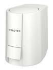


Type designation
Technical data
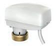
Technical data
Direction of closure
Method
Stroke
2-point
3-point
Combination options with valve
Further information Page 168 Page 170 Page 171
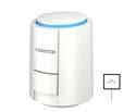
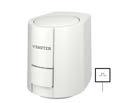
Features
• Actuation of unit valves and valves in surface heating and cooling systems as well as fan coils
• Low-force fitting on the valve using adapter ring
• NC “normally closed” and NO “normally open” versions
• NC version with first-open function
• Adaptation to valve using plastic adapter M30 × 1.5 or M28 × 1.5
• Max. closing force 125 N
• With 230 V or 24 V thermal expansion element
• Large visible and tactile position indicator
• Low-noise and maintenance-free
• Contemporary design
• High functional quality and service life
• Version with integrated auxiliary contact
• Standard version with 1-metre cable permanently connected
• Version with 2 m or 5 m plug-in cable
• Can be mounted in any position, even suspended under the valve
Technical data
Power supply
AXT301HF110/112
Ambient conditions
Construction
Standards, directives
Power supply 230 VAC ±10% 50…60 Hz
Power supply 24 VAC/DC +20%…−10%
Power consumption during operation1) Approx. 1 W
Start-up current 230 VAC < 550 mA after max. 100 ms
Start-up current 24 VAC/DC< 300 mA after max. 2 min.
Power for auxiliary contacts 230 V5(1) A, 50/60 Hz
Power for auxiliary contacts 24 V3(1) A, 50/60 Hz
Changeover point of auxiliary contactFor approx. 2 mm stroke
Ambient temperature 0…60 °C
Storage and transport temperature−25…60 °C
Operating temperature at valveMax. 100 °C
Air humidity < 85% rh, no condensation
Housing
White (RAL 9003), surface structured according to VDI 3400 Ref. 27
Housing material Polyamide
Power cable2)
PVC hose line (H03V2V2-F), Ø 0.75 mm², fixed mounting, light grey (RAL 7035)
Weight 0.1 kg (with 1 m power cable)
Type of protection

IP54
Protection class 230 V II (EN 60730-1)
Protection class 24 V III (EN 60730-1)
1) Power consumption after expansion element has reached steady temperature state
2) AXT301F100 and F102 without pre-assembled cable
CE/UKCA conformity3) LVD 2014/35/EU (CE)
EESR-2016 (UKCA)
EN 60730-1, EN 60730-2-14
EN 60730-1, EN 60730-2-14
EMC-D 2014/30/EU (CE)EN 60730-1/-2/-14 (mode of operation 1, residential premises)
EMC-2016 (UKCA)
RoHS-D 2011/65/EU & 2015/863/EU (CE)
RoHS-2012 (UKCA)
EN 60730-1/-2/-14 (mode of operation 1, residential premises)
EN IEC 63000
EN IEC 63000
Overview of types
AXT301F110230 VAC5.0 mm100 N4.0 minNC1 m–
AXT301F11224 VAC/DC5.0 mm100 N4.0 minNC1 m–
AXT301F210230 VAC5.0 mm100 N4.0 minNO1 m–
AXT301F21224 VAC/DC5.0 mm100 N4.0 minNO1 m–
AXT301F100230 VAC5.0 mm100 N4.0 minNCWithout cable–
AXT301F10224 VAC/DC5.0 mm100 N4.0 minNCWithout cable–
AXT301HF110230 VAC5.0 mm100 N3.5 minNC1 mAuxiliary contacts
AXT301HF11224 VAC/DC5.0 mm100 N3.5 minNC1 mAuxiliary contacts
AXT311F110230 VAC6.5 mm125 N4.5 minNC1 m–
AXT311F11224 VAC/DC6.5 mm125 N4.5 minNC1 m–
A AXT301F100/102: Connection cable available as optional accessory
A AXT301F*1*: Including adapter ring 0550389K008 M30 × 1.5 for closing dimension 10.5 mm, pack of one
A AXT311F11*: Including adapter ring 0550389K008 M30 × 1.5 for closing dimension 8.5 mm in combination with Frese or Siemens PICV valves
Accessories
/ Valveadapters:The names of the manufacturers are provided for information purposes. Manufacturers may change the closing dimensions without prior notice.
Type Delivery quantityDescription
0550389K001Set of 5VA 10 adapter, plastic, light grey, M30 × 1.5
Suitable for: Dumser, Beulco (from 2005), Purmo, Strawa, Oventrop (also Cocon, Cocon 4, Hycocon,), Oventrop stainless steel distributor, Vescal (Metaplast), Cronatherm, eht Siegmund, Gampper, KaMo (H) before Sept. 2005, Aquatherm (brass distributor), Valvex brass distributor, Viega stainless steel distributor (Fonterra & pro Radiant), Thermotech, KaMo INOX distributor, Bianchi valves (series 401T & 403T) and brass distributor (series 332T), Unipipe (ECO distributor), CronaTech, Fränkische, Zehnder, ATS stainless steel distributor, Frese Optima (2.5 mm), Hesag/Herb (Profi-Line distributor), Luxor (CD distributor), TECE stainless steel (Strawa), Watts brass distributor (HKV-T), Tiemme valves, Watts (Vogel & Noot, Cosmo Objektline), Acome (Strawa), Multibeton HKV (Oventrop)
0550389K101Set of 100Adapter like 0550389K001
0550389K002Set of 5VA 16 adapter, plastic, red, M28 × 1.5
Suitable for: Polytherm (H), Buderus, Thermoval, KAN-Therm (brass distributor)
0550389K102Set of 100Adapter like 0550389K002
0550389K003Set of 5VA 17 adapter, plastic, dusty grey, M28 × 1.5
Suitable for: MMA (EDVH 25, FVXR 15, VXR 20), ICMA (BAS), industry technology Italy (DB VZ2)
0550389K103Set of 100Adapter like 0550389K003
Closing dimension
3) Explanation of abbreviations in the “Additional technical information” section of this product data sheet and in the appendix to SAUTER product catalogues
Type
Delivery quantityDescription
0550389K004Set of 5VA 26 adapter, plastic, dusty grey, M30 × 1.5
Suitable for: Giacomini
0550389K104Set of 100Adapter like 0550389K004
0550389K005Set of 5VA 50 adapter, plastic, dark grey, M30 × 1.5
Suitable for: Honeywell & Braukmann, Broen (type: Ballorex Dynamic), Böhnisch/SBK (before 1998), Cazzaniga, Reich, MNG (before 1998), Frese, Schütz, Seppelfricke, Cufix, KaMo (from Sept. 2005), FAR (from 2007), Pantherm, Unicor, emcal (stainless steel from March 2013), Comap HKV module, black (H)
0550389K105Set of 100Adapter like 0550389K005
0550389K006Set of 5VA 64 adapter, plastic, pure white
Suitable for: Pettinaroli
0550389K106Set of 100Adapter like 0550389K006
0550389K007Set of 5VA 78 adapter, plastic, pure white
Suitable for: Danfoss RA, Oventrop type: V3D, GD & GDF, Jaga
0550389K107Set of 100Adapter like 0550389K007
0550389K008Set of 5VA 80 adapter, plastic, pure white, M30 × 1.5 Suitable for: Heimeier, Herb, Onda, IVAR, Thermoval, Schlösser (from 1993), Kermi, Cazzaniga, Oventrop, Multiblock (from 1997), Frank (from 2003), Athe-Therm (brass up to Feb. 2005), Athe-Therm (stainless steel), BHS distributor, Jupiter, Böhnisch/SBK (from 1998), Simplex, RBM, Emmeti, Cosmo, Watts, Roth, Delphis-Therm, GC distributor, Cuprotherm, Caleffi distributor series 670 (plastic), Wieland, Caleffi, SKV distributor, Aquatechnik Italy (Multirapid, before 2007, from 2009), Brugman, TKM, Bianchi, Jaga, Gomacal, Nereus angle valve DN 10, Strasshofer, Taco (Vogel & Noot, Cosmo stainless steel and CMV module distributor), Caleffi (with thread ring on manufacturer side), Watts, Vogel & Noot (Cosmo brass distributor), RDZ (brass distributor), VIR (series 9520), Herz regulating valve and distributor
0550389K108Set of 100Adapter like 0550389K008
0550389K009Set of 5VA 90 adapter, plastic, crimson, M30 × 1.5 Suitable for: Chemidro, TECE (plastic distributor), KWH Pipe, Prandelli (brass HKV), Athe-Therm (brass from Feb. 2005), Roth DE (H) (type: Universal HK2), Uponor stainless steel distributor, Reliance stainless steel, SAS brass distributor, Luxor, Tiemme brass distributor (series: ‘Floor’), Honeywell VSMF, Afriso pro Calida EF1 (plastic)
0550389K109Set of 100Adapter like 0550389K009
0550389K010Set of 5VA 41 adapter, plastic, dark green, M30 × 1.5
Suitable for: Danfoss AB-QM (DN 10–DN 20) (4 mm actuator), Danfoss AB-QM (DN 25–DN 32) (5 mm actuator), RDZ (plastic distributor), Vescal (Cazzaniga), Frese Optima Compact and EVA (from 2016) + 5 mm actuator
0550389K110Set of 100Adapter like 0550389K010
Closing
05506002021x 2 metresPVC flat cable H03V2V2H2-F, 2-core, 0.75 mm² –
05506002121x 2 metresThermoplastic cable H03Z1Z1-F, 2-core, 0.75 mm², halogen-free –
05506005021x 5 metresPVC flat cable H03V2V2H2-F, 2-core, 0.75 mm² –
05506005121x 5 metresThermoplastic cable H03Z1Z1-F, 2-core, 0.75 mm², halogen-free –
A The cables for the AXT301F100 and AXT301F102 actuators must be ordered separately and can be fitted as required on site. It is not possible to install the cables at the factory
A Special covers to prevent theft or vandalism, for example, are available on request
Features
• Actuation of unit valves and valves in surface heating and cooling systems as well as fan coils
• First-open function for low-force fitting on the valve using adapter ring
• NC “normally closed” and NO “normally open” versions
• NC version with first-open function
• Adaptation to valve using plastic adapter M30 × 1.5 or M28 × 1.5
• Max. closing force 125 N
• With 24 V thermal expansion element
• Large visible and tactile position indicator
• Low-noise and maintenance-free
• Contemporary design
• High functional quality and serviceable life
• Version with 1m, 2m or 5m plug-in cable
• PVC or halogen-free cable, with or without position feedback signal, available as an accessory
• Can be mounted in any position, even suspended under the valve
Technical data
Power supply
Parameters
Ambient conditions
Construction
Power supply 24 VAC −10%, +20%, 50…60 Hz
Power supply 24 VDC −20%…+20%
Power consumption during operation1) 1.2 W
Start-up current < 320 mA after max. 2 minutes
Stroke2) 6.5 mm
Closing force 125 N +5%
Running time3) 30 s/mm
Control signal 0…10 V
Control signal input resistance100 kΩ
Positional feedback signal 0…10 V (0.1 V resolution)
Position feedback signal output impedance 10 kΩ
Position feedback signal output current0.1 mA (1 mA if shorted)
Output load impedance 100 kΩ…1000 kΩ
Ambient temperature
0…50 °C
Storage and transport temperature−25…60 °C
Operating temperature at valveMax. 100 °C
Air humidity < 85% rh, no condensation
Housing
White (RAL 9003), surface structured according to VDI 3400 Ref. 27
Housing material Polyamide
Power cable4) Ø 0.22 mm², 3- or 4-core, signal white (RAL 9003)
Weight 0.15 kg (without power cable)
1) Power consumption after expansion element has reached steady temperature state
2) Stroke, incl. 0.5 mm overstroke range; see “Initialisation”
3) Running time, see “Runtime behaviour”
4) Order the power cable separately

Standards, directives
CE/UKCA conformity5)
Type of protection
LVD 2014/35/EU (CE)
EESR-2016 (UKCA)
IP54
EN 60730-1, EN 60730-2-14
EN 60730-1, EN 60730-2-14
EMC-D 2014/30/EU (CE)EN 60730-1/-2/-14 (mode of operation 1, residential premises)
EMC-2016 (UKCA) EN 60730-1/-2/-14 (mode of operation 1, residential premises)
RoHS-D 2011/65/EU & 2015/863/EU (CE)
RoHS-2012 (UKCA)
EN IEC 63000
EN IEC 63000
Overview of types
Type Features
AXS315SF102Actuator for unit valves with first-open function, normally closed (NC)
AXS315SF202Actuator for unit valves, normally open (NO)
A Order the power cable 0550600*** separately, see accessories
A Includes adapter ring 0550389K010 suitable for SAUTER VUL, VDL, VUT, BUT and BXL valves
A Adapter ring 0550389K008 suitable for SAUTER BUL valve must be ordered separately
Accessories
/ The names of the manufacturers in the following list are provided for information purposes. Manufacturers may change the closing dimensions without prior notice.
Type Delivery quantityDescription Closing dimension 0550389K001Set of 5VA 10 adapter, plastic, light grey, M30 × 1.5
Suitable for: Dumser, Beulco (from 2005), Purmo, Strawa, Oventrop (also Cocon, Cocon 4, Hycocon,), Oventrop stainless steel distributor, Vescal (Metaplast), Cronatherm, eht Siegmund, Gampper, KaMo (H) before Sept. 2005, Aquatherm (brass distributor), Valvex brass distributor, Viega stainless steel distributor (Fonterra & pro Radiant), Thermotech, KaMo INOX distributor, Bianchi valves (series 401T & 403T) and brass distributor (series 332T), Unipipe (ECO distributor), CronaTech, Fränkische, Zehnder, ATS stainless steel distributor, Frese Optima (2.5 mm), Hesag/Herb (Profi-Line distributor), Luxor (CD distributor), TECE stainless steel (Strawa), Watts brass distributor (HKV-T), Tiemme valves, Watts (Vogel & Noot, Cosmo Objektline), Acome (Strawa), Multibeton HKV (Oventrop)
0550389K101Set of 100Adapter like 0550389K001
0550389K002Set of 5VA 16 adapter, plastic, red, M28 × 1.5
Suitable for: Polytherm (H), Buderus, Thermoval, KAN-Therm (brass distributor)
0550389K102Set of 100Adapter like 0550389K002
0550389K003Set of 5VA 17 adapter, plastic, dusty grey, M28 × 1.5
Suitable for: MMA (EDVH 25, FVXR 15, VXR 20), ICMA (BAS), industry technology Italy (DB VZ2)
0550389K103Set of 100Adapter like 0550389K003
0550389K004Set of 5VA 26 adapter, plastic, dusty grey, M30 × 1.5
Suitable for: Giacomini
0550389K104Set of 100Adapter like 0550389K004
5) Explanation of abbreviations in the “Additional technical information” section of this product data sheet and in the appendix to SAUTER product catalogues
Type
0550389K005Set of 5VA 50 adapter, plastic, dark grey, M30 × 1.5
Suitable for: Honeywell & Braukmann, Broen (type: Ballorex Dynamic), Böhnisch/SBK (before 1998), Cazzaniga, Reich, MNG (before 1998), Frese, Schütz, Seppelfricke, Cufix, KaMo (from Sept. 2005), FAR (from 2007), Pantherm, Unicor, emcal (stainless steel from March 2013), Comap HKV module, black (H)
0550389K105Set of 100Adapter like 0550389K005
0550389K006Set of 5VA 64 adapter, plastic, pure white
Suitable for: Pettinaroli
0550389K106Set of 100Adapter like 0550389K006
0550389K007Set of 5VA 78 adapter, plastic, pure white
Suitable for: Danfoss RA, Oventrop type: V3D, GD & GDF, Jaga
0550389K107Set of 100Adapter like 0550389K007
0550389K008Set of 5VA 80 adapter, plastic, pure white, M30 × 1.5
Suitable for: Heimeier, Herb, Onda, IVAR, Thermoval, Schlösser (from 1993), Kermi, Cazzaniga, Oventrop, Multiblock (from 1997), Frank (from 2003), Athe-Therm (brass up to Feb. 2005), Athe-Therm (stainless steel), BHS distributor, Jupiter, Böhnisch/SBK (from 1998), Simplex, RBM, Emmeti, Cosmo, Watts, Roth, Delphis-Therm, GC distributor, Cuprotherm, Caleffi distributor series 670 (plastic), Wieland, Caleffi, SKV distributor, Aquatechnik Italy (Multirapid, before 2007, from 2009), Brugman, TKM, Bianchi, Jaga, Gomacal, Nereus angle valve DN 10, Strasshofer, Taco (Vogel & Noot, Cosmo stainless steel and CMV module distributor), Caleffi (with thread ring on manufacturer side), Watts, Vogel & Noot (Cosmo brass distributor), RDZ (brass distributor), VIR (series 9520), Herz regulating valve and distributor
0550389K108Set of 100Adapter like 0550389K008
0550389K009Set of 5VA 90 adapter, plastic, crimson, M30 × 1.5
Suitable for: Chemidro, TECE (plastic distributor), KWH Pipe, Prandelli (brass HKV), Athe-Therm (brass from Feb. 2005), Roth DE (H) (type: Universal HK2), Uponor stainless steel distributor, Reliance stainless steel, SAS brass distributor, Luxor, Tiemme brass distributor (series: ‘Floor’), Honeywell VSMF, Afriso pro Calida EF1 (plastic)
0550389K109Set of 100Adapter like 0550389K009
0550389K010Set of 5VA 41 adapter, plastic, dark green, M30 × 1.5
Suitable for: Danfoss AB-QM (DN 10–DN 20) (4 mm actuator), Danfoss AB-QM (DN 25–DN 32) (5 mm actuator), RDZ (plastic distributor), Vescal (Cazzaniga), Frese Optima Compact and EVA (from 2016) + 5 mm actuator
0550389K110Set of 100Adapter like 0550389K010
05506001031x 1 metrePower cable, 0…10 V, 3-core, 0.22 mm², type LiYY, PVC
05506002031x 2 metresPower cable, 0…10 V, 3-core, 0.22 mm², type LiYY, PVC
05506005031x 5 metresPower cable, 0…10 V, 3-core, 0.22 mm², type LiYY, PVC
05506001131x 1 metrePower cable, 0…10 V, 3-core, 0.22 mm², type LiZ1Z1, halogen-free
05506002131x 2 metresPower cable, 0…10 V, 3-core, 0.22 mm², type LiZ1Z1, halogen-free
05506005131x 5 metresPower cable, 0…10 V, 3-core, 0.22 mm², type LiZ1Z1, halogen-free
05506001141x 1 metrePower cable, 0…10 V, 4-core, 0.22 mm², type LiZ1Z1, halogen-free, position feedback
0550600214 1x 2 metresPower cable, 0…10 V, 4-core, 0.22 mm², type LiZ1Z1, halogen-free, position feedback
0550600514 1x 5 metresPower cable, 0…10 V, 4-core, 0.22 mm², type LiZ1Z1, halogen-free, position feedback
A Special covers to prevent theft or vandalism, for example, are available on request
10.5 mm
mm
AXF217SF404
AXF217SF405
Features
• Stepping motor with electronic activation and cut-out
• Attached to valve with M30 × 1.5 thread
• Version with direction of operation 1 (direct acting) or 2 (reverse acting), adjustable
• Adjustable valve strokes
• Automatic stroke adjustment
• Electrical reset function
• Maintenance-free gear unit
• Suitable for retrofitting existing installations using the appropriate adapters
• Status and diagnostic indicator via integrated bi-colour LED
• Fitting position vertically upright to horizontal, not suspended
Technical data
Power supply
Parameters1)
Ambient conditions
Construction
Standards, directives

Power supply
24 V~ ±15%, 50…60 Hz 24 V= ±15%
Power consumption 5 VA while charging, 2,5 VA during operation, 1 W at standstill
Direction of operation 1 or 2 (adjustable)
Nominal stroke Max. 6 mm
Automatic stroke adjustment
Running time 8 s/mm
Closing dimension
H0:10 mm
Actuating power 160 N
Sound pressure level < 30 dB (A)
Control signal 0(2)…10 V; 5…10 V; 0…5 V Ri > 100 kΩ; 0(4)…20 mA
Ri = 500 Ω
Feedback signal 0…10 V=, ±5%
Charging time 150 s (supercapacitor)
Ambient temperature 0...50 °C, no condensation
Max. operating temperature at valve95 °C
Storage and transport temperature−20…65 °C
Ambient humidity < 90% rh
Weight 0.2 kg
Housing Two-piece, light grey (RAL 7035)
Housing material Plastic
Thread Nickel-plated brass M30 × 1.5
Power cable 1.50 m long, halogen-free 4 × 0.5 mm², light grey, insertable
Type of protection
IP54 (EN 60529)
1) The direction of operation and the control voltage can be set using accessory 0550360010 (configurator); factory setting “1” (DA). Direction of operation 1: Control signal increasing = actuator moves out (valve VUT, VUL, VXL, VDL, BUL, BUT closes, valve BXL (control passage) opens). Direction of operation2: Control signal increasing = actuator moves in (valve VUT, VUL, VXL, VDL, BUL, BUT opens, valve BXL (control passage) closes)
Protection class III (IEC 60730)
CE conformity according toEMC Directive 2014/30/EU60730-1, 60730-2-14
Overview of types
Type Features
AXF217SF404Motorised actuator for unit valves with positioner, automatic stroke adjustment, electrical reset function:Spindle extends (EFSD)
AXF217SF405 Motorised actuator for unit valves with positioner, automatic stroke adjustment, electrical reset function:Spindle retracts (EFSU)
Accessories
Type Description
0550360010Configurator for changing control signal, direction of operation, characteristic, direction of reset function
Features
• Reliable actuation in efficient control systems
• For 2-point or 3-point controllers in conjunction with single-room control systems
• Stepping motor with electronic activation and cut-out
• Attached to valve with M30 × 1.5 thread
• Maintenance-free gear unit
• Suitable for retrofitting existing installations using the appropriate adapters
• Operating status indicated by integrated LED
• Fitting position vertically upright to horizontal, not suspended
Technical data
Parameters
Ambient conditions
Construction
Nominal stroke
6.3 mm
Running time 13 s/mm
Actuating power1) 120 N
Sound pressure level < 30 dB (A)
Max. operating temperature at valve90 °C
Ambient temperature 0...50 °C
Ambient humidity < 75% rh
Weight
Housing
0.15 kg
Two-piece, light grey RAL 7035
Housing material Plastic
Thread
Power cable
Standards and directives
Overview of types
Type Power supply
Type of protection
Nickel-plated brass M30 × 1.5
1.50 m long, 3 × 0,5 mm², light grey, insertable
IP43 (EN 60529)
EMC Directive 2014/30/EUCE as per EN 61000-6-1, EN 61000-6-2, EN 61000-6-3, EN 61000-6-4
Low-Voltage Directive 2014/35/EUCE as per EN 60730-1 and EN 60730-2-14
Power consumption Protection class
AXM217F200230 V~, ±10%, 50...60 Hz6.5 VA, 2 W II (IEC 60730)
AXM217F20224 V~, ±15%, (50...60 Hz)2.5 VA, 1.5 W III (IEC 60730)
A AXM217F202: Voltage 24V= with relay circuit only
Accessories
Type Description
0550603001Cable: 24 V, PVC, pluggable, 3 m long
0550603005Cable: 24 V, halogen-free, pluggable, 3 m long

1) Actuating power min. 100 N, max. 150 N
Features
• Stepping motor with electronic activation and cut-out
• Attached to valve with M30 × 1.5 thread
• Version with direction of operation 1 (direct acting) or 2 (reverse acting), adjustable
• Adjustable valve strokes
• Automatic stroke adjustment (AXM217SF404)
• Maintenance-free gear unit
• Suitable for retrofitting existing installations using the appropriate adapters
• Status and diagnostic indicator via integrated bi-colour LED
• Fitting position vertically upright to horizontal, not suspended
Technical data
Power supply
Parameters1)
Power supply
Power consumption
24 VAC/DC ±15 %, 50...60 Hz
2.5 VA / 1.5 W
Direction of operation 1 or 2 (adjustable)
Nominal stroke
3.2 mm, 4.3 mm, 5.5 mm (adjustable) Automatic stroke adjustment (F404)
Running time 8 s/mm
Sound pressure level < 30 dB (A)
Control signal
Ambient conditions
Construction
Ambient temperature
0(2)...10 V; 5...10 V; 0...5 V
Ri > 100 kΩ; 0(4)...20 mA
Ri = 500 Ω
0…50 °C, no condensation
Max. operating temperature at valve95 °C
Storage and transport temperature−20…65 °C
Ambient humidity < 75% rh
Weight
Housing
0.15 kg
Two-piece, light grey (RAL 7035)
Housing material Plastic
Thread Nickel-plated brass M30 × 1.5
Power cable
Standards, directives
Type of protection
1.50 m long, 3 × 0.5 mm², light grey, pluggable
3.0 m long, halogen-free (F404)
IP43 (EN 60529)
Protection class III (IEC 60730)
CE conformity according toEMC Directive 2014/30/EU61000-6-1, 61000-6-2, 61000-6-3 and EN 61000-6-4
1) Direction of operation and control signal can be adjusted using DIP switches. Direction of operation 1: Control signal increasing = actuator moves out (valve VUT, VUL, VCL, VDL, BUL closes and valve BXL (control passage) opens). Direction of operation 2: Control signal increasing = actuator moves in (valve VUT, VUL, VCL, VDL, BUL opens and valve BXL (control passage) closes). Factory setting: Direction of operation 2 (RA)

Valves, control valves, dampers, actuators | Unit valves and actuators for unit valves
Overview of types
Type Features
Actuating power
AXM217SF402Motorised actuator for unit valves with positioner120 N
AXM217SF404Motorised actuator for unit valves with positioner and automatic stroke adjustment 160 N
A AXM217SF402: Actuating power min. 100 N, max. 150 N
Accessories
Type Description
0550603009Cable: 24 V, PVC, pluggable, 3 m long
0550603010Cable: 24 V, PVC, pluggable, 7 m long
0550603011Cable: 24 V, halogen-free, pluggable, 3 m long
0550603012Cable: 24 V, halogen-free, pluggable, 7 m long
SAUTER regulating valves provide flexible combinations for all requirements. The wide product range at SAUTER comprises threaded valves made of DZR cast brass and flanged valves made of grey cast iron, ductile cast iron or cast steel, ensuring that you will find products that suit your requirements perfectly. These regulating valves can be used for the continuous control of hot and cold water in closed circuits.
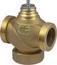
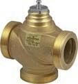
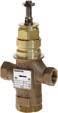
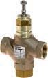
Application
Preheater for ventilation & air-conditioning
Cooler for ventilation & air-conditioning
Steam humidifier for ventilation & air-conditioning
Reheater for ventilation & air-conditioning
Chilled ceiling, underfloor heating
Static heating
Cooling tower (open systems)
Multi-boiler system
District heating
Version
2-way
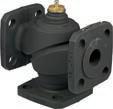
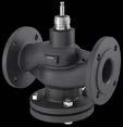

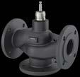
for ventilation & air-conditioning
for ventilation & air-conditioning
humidifier for ventilation & air-conditioning
Reheater for ventilation & air-conditioning
ceiling, underfloor heating
tower (open systems)
Combination options with actuator
Further information Page 188 Page 191 Page 193 Page 196
for ventilation & air-conditioning
for ventilation & air-conditioning
Steam humidifier for ventilation & air-conditioning
Reheater for ventilation & air-conditioning
ceiling, underfloor heating
(open systems)
Combination options with actuator
AVM 105, AVM 115, AVM 321(S)
AVM 234S, AVM 322(S), AVF 234S
AVM 105, AVM 115, AVM 321(S)
AVM 234S, AVM 322(S), AVF 234S
Further information Page 198 Page 202 Page 204 Page 208
Application Preheater for ventilation & air-conditioning
for ventilation & air-conditioning
humidifier for ventilation & air-conditioning
for ventilation & air-conditioning
ceiling, underfloor heating
Combination options with actuator
AVF 234S, AVN 224S, AVM 322(S)
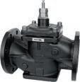
AVF 234S, AVN 224S, AVM 322(S)
AVF 234S, AVN 224S, AVM 322(S)
Further information Page 211 Page 215 Page 218
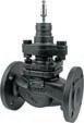
for ventilation & air-conditioning
for ventilation & air-conditioning
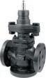
Further information Page 220 Page 223
Features
• Regulating valve free of silicone grease with male thread (DIN EN ISO 228-1) for cold or hot water in closed and open circuits
• In combination with valve actuators AVM 105(S), 115(S), 321(S) and AVF 124, 125S as a control unit
• Equal-percentage (F300) / linear (F200) characteristic, can be set with SUT valve actuators (SAUTER Universal Technology)
• The valve is closed when the spindle is moved out
• Closing procedure against the pressure or with the pressure
• Stainless-steel spindle
• Valve body and valve seat in dezincification-resistant (DZR) cast brass
• Plug made of dezincification-resistant cast brass (DZR) with EPDM sealing ring
• Stuffing box with wiper ring made of dezincification-resistant (DZR) cast brass and double O-ring seal made of EPDM
Technical data
Parameters
Ambient conditions
Nominal pressure 16 bar
Control ratio > 50:1
Valve characteristic F200 = linear F3*0 = equal-percentage
Nominal stroke 8 mm
Leakage rate ≤ 0.02% of Kvs value
Operating temperature1) −10...130 °C
Operating pressure up to 120 °C16 bar
Operating pressure up to 130 °C13 bar
Overview of types

VUN050F200DN 50
Accessories
Type Description
0361951015Screw fitting for male thread with flat seal DN 15
0361951020Screw fitting for male thread with flat seal DN 20
0361951025Screw fitting for male thread with flat seal DN 25
0361951032Screw fitting for male thread with flat seal DN 32
1) Use stuffing box heater at temperatures below 0 °C; use temperature adapter (accessory) at temperatures above 100 °C
Type Description
0361951040Screw fitting for male thread with flat seal DN 40
0361951050Screw fitting for male thread with flat seal DN 50
0372240001Manual adjustment for valves with 8 mm stroke
0372249001Adaptor required when temperature of the medium is 100...130 °C (recommended for temperatures <10 °C)
0372249002 Adaptor required when temperature of the medium is 130...150 °C
0378284100Stuffing box heater 230V~, 15 W for medium below 0 °C
0378284102Stuffing box heater 24V~, 15 W for medium below 0 °C
0378368001Complete replacement stuffing box for DN 15...50
/ Warranty: The technical data and pressure differences indicated here are applicable only in combination with SAUTER valve actuators. The warranty does not apply if used with valve actuators from other manufacturers.
/ Definitionof∆ps:Maximum admissible pressure drop in the event of a malfunction (pipe break after the valve) at which the actuator reliably closes the valve by means of a return spring.
/ Definitionof∆pmax:Maximum admissible pressure drop in control mode at which the actuator reliably opens and closes the valve.
Pressure differences
Page 228 228 231 229 231
Actuating power250 N 250 N 250 N 500 N 500 N
Control signal2-/3-point2-/3-point2-/3-point, 0...10 V2-/3-point2-/3-point, 0...10 V
Running time30 s 120 s 35/60/120 s120 s 60/120 s
Closes against the pressure
Cannot be used to close with the pressure ActuatorAVM321F110
Closes
VUN015F350
VUN015F340
VUN015F330 VUN015F320
VUN015F310
VUN015F300
Features
• Regulating valve free of silicone grease with male thread (DIN EN ISO 228-1) for cold and hot water in closed and open circuits
• In combination with valve actuators AVM 105(S), 115(S), 321(S) and AVF 124, 125S as a control unit
• Equal-percentage (F300) / linear (F200) characteristic, can be set with SUT valve actuators (SAUTER Universal Technology)
• The valve is closed when the spindle is moved out
• Can be used as a control valve or a distribution valve
• Stainless-steel spindle
• Valve body with valve seat made from dezincification-resistant cast brass (DZR)
• Plug made of dezincification-resistant cast brass (DZR) with EPDM sealing ring
• Stuffing box with wiper ring made from dezincification-resistant cast brass (DZR) and double O-ring seal made from EPDM
Technical data
Parameters
Nominal pressure 16 bar
Valve characteristic, control passageF200 = linear F3*0 = equal percentage
Mixing passage valve characteristicLinear
Control ratio > 50:1
Control passage leakage rate≤ 0.05% of kvs value
Mixing passage leakage rate≤ 1% of Kvs value
Nominal stroke 8 mm
Ambient conditions
Overview of types
Accessories
Distribution valve
Control valve
1) Use stuffing box heater at temperatures below 0 °C; use temperature adapter (accessory) at temperatures above 100 °C

Type
Description
0361951040Screw fitting for male thread with flat seal DN 40
0361951050Screw fitting for male thread with flat seal DN 50
0372240001Manual adjustment for valves with 8 mm stroke
0372249001Adaptor required when temperature of the medium is 100...130 °C (recommended for temperatures <10 °C)
0372249002 Adaptor required when temperature of the medium is 130...150 °C
0378284100Stuffing box heater 230V~, 15 W for medium below 0 °C
0378284102Stuffing box heater 24V~, 15 W for medium below 0 °C
0378368001Complete replacement stuffing box for DN 15...50
/ Warranty: The technical data and pressure differences indicated here are applicable only in combination with SAUTER valve actuators. The warranty does not apply if used with valve actuators from other manufacturers.
/ Definitionof∆ps:Maximum admissible pressure drop in the event of a malfunction (pipe break after the valve) at which the actuator reliably closes the valve by means of a return spring.
/ Definitionof∆pmax:Maximum admissible pressure drop in control mode at which the actuator reliably opens and closes the valve.
Pressure differences
Page
Actuating power250 N 250 N 250 N 500 N 500 N
Control signal2-/3-point2-/3-point2-/3-point,
A At temperatures above 100 °C, accessories are required
Valves, control valves, dampers, actuators | Regulating valves and valve actuators
Features
• Regulating valve free of silicone grease with female thread DIN EN ISO 228-1 G for the control of cold/hot water in closed and open circuits
• In combination with valve actuators AVM 322, AVM 322S, AVM 234S, AVF 234S
• Equal-percentage or linear characteristic, can be set with SUT valve actuators (SAUTER Universal Technology) to linear or equal-percentage
• Control passage A–AB closed when the spindle is moved out
• Closing procedure against the pressure or with the pressure
• Valve body and seat made of gunmetal
• Stainless-steel spindle
• Stuffing box made of brass with wiper ring and double O-ring seal made of EPDM
Technical data
Parameters
Ambient conditions
ValveDim app
Standards, directives
Control ratio > 50:1
Leakage rate ≤ 0.05% of Kvs value
Valve stroke 14 mm
Nominal pressure 16 bar
Operating temperature1) −15...130 °C
Operating pressure up to 120 °C16 bar
Operating pressure up to 130 °C13 bar
Pressure and temperature dataDIN 2401
Flow parameter VDI/VDE 2173
Overview of types
V6R15F350DN 150.4 m³/hEqual-percentageStainless steelG½"1.2
V6R15F340DN 150.63 m³/hEqual-percentageStainless steelG½"1.2 kg
V6R15F330DN 151 m³/hEqual-percentageStainless steelG½"1.2 kg
V6R15F320DN 151.6 m³/hEqual-percentageStainless steelG½"1.2 kg
V6R15F310DN 152.5 m³/hEqual-percentageBrass G½"1.2 kg
V6R15F300DN 154 m³/hEqual-percentageBrass G½"1.2 kg
V6R15F200DN 154 m³/hLinear Brass G½"1.2 kg
V6R25F310DN 256.3 m³/hEqual-percentageBrass G1"1.6 kg
V6R25F300DN 2510 m³/hEqual-percentageBrass G1"1.6 kg
V6R25F210DN 256.3 m³/hLinear Brass G1"1.6 kg
V6R25F200DN 2510 m³/hLinear Brass G1"1.6 kg
V6R40F310DN 4016 m³/hEqual-percentageBrass G1½"3.4 kg
V6R40F300DN 4025 m³/hEqual-percentageBrass G1½"3.4 kg
V6R40F210DN 4016 m³/hLinear Brass G1½"3.4 kg
V6R40F200DN 4025 m³/hLinear Brass G1½"3.4 kg
V6R50F300DN 5035 m³/hEqual-percentageBrass G2"4.6 kg
V6R50F200DN 5035 m³/hLinear Brass G2"4.6 kg

1) At temperatures below 0 °C, use stuffing box heater (accessory)
Accessories
Type Description
0217268001Stuffing box heater 15 W, 24 V 0217268004Stuffing box heater 15 W, 230 V 0360391015Screw fitting, DN 15, incl. seal, 2 pcs. required 0360391025Screw fitting, DN 25, incl. seal, 2 pcs. required 0360391040Screw fitting incl. seal, 2 pcs. required, Rp1½ - G1½ 0360391050Screw fitting incl. seal, 2 pcs. required, Rp2 - G2 0360427000Stuffing box, complete with O-ring, max. 130 °C
A 0217268***Stuffing box heater 15 W, light alloy housing, IP54, 3 × 0.75 mm² power cable, earth connector, length 1 m, ferrule
Combination of V6R with electrical actuators
/ Warranty: The technical data and pressure differences indicated here are applicable only in combination with SAUTER valve actuators. The warranty does not apply if used with valve actuators from other manufacturers.
/ Definitionof∆ps:Maximum admissible pressure drop in the event of a malfunction (pipe break after the valve) at which the actuator reliably closes the valve by means of a return spring.
/ Definitionof∆pmax:Maximum admissible pressure drop in control mode at which the actuator reliably opens and closes the valve.
Pressure differences
ActuatorAVM234SF132AVF234SF132 AVF234SF232
Actuating
AVM322F120 AVM322F122
Control signal 2-/3-point, 0…10 V, 4…20 mA 2-/3-point, 0…10 V, 4…20 mA 2-/3-point 2-/3-point, 0…10 V, 4…20 mA
Running time28/56/84 s 28/56/84 s 120/240 s 120/80 s
Closes against the pressure
V6R15F350
V6R15F340
V6R15F330
V6R15F320
V6R15F310
V6R15F300
V6R15F200
V6R25F310
V6R25F300
V6R25F210
V6R25F200
V6R40F310
V6R40F300
Closes with the pressure
V6R15F350
V6R15F340
V6R15F330
V6R15F320
V6R15F310
V6R15F300
V6R15F200
V6R25F310
V6R25F300
V6R25F210
V6R25F200
Valves, control valves, dampers, actuators | Regulating valves and valve actuators
A Accessories required: Mounting set 0372338001 for AVM 234 and AVF 234
A Accessories required: Mounting set 0510240012 for AVM 322(S)
Features
• Regulating valve free of silicone grease with female thread DIN EN ISO 228-1 G for the control of cold/hot water in closed and open circuits
• In combination with valve actuators AVM 322, AVM 322S, AVM 234S, AVF 234S
• Equal-percentage or linear characteristic, can be set with SUT valve actuators (SAUTER Universal Technology) to linear or equal-percentage
• Control passage A–AB closed when the spindle is moved out
• Can be used as a control valve or a distribution valve
• Valve body and seat made of gunmetal
• Stuffing box made of brass with wiper ring and double O-ring seal made of EPDM
• Stainless-steel spindle
Technical data
Parameters
Ambient conditions
Standards, directives
Control ratio > 50:1
Leakage rate of control passage A–AB≤ 0.05% of Kvs value
Leakage rate of mixing passage B–AB≤ 1% of Kvs value
Valve stroke 14 mm
Mixing passage valve characteristicLinear
Operating temperature1) −15...130 °C
Operating pressure up to 120 °C16 bar
Operating pressure up to 130 °C13 bar
Pressure and temperature dataDIN 2401
Flow parameter VDI/VDE 2173
Overview
B6R15F330DN 151 m³/hEqual-percentageStainless steelG½"1.2
B6R15F320DN 151.6 m³/hEqual-percentageStainless steelG½"1.2 kg
B6R15F310DN 152.5 m³/hEqual-percentageBrass G½"1.2 kg
B6R15F300DN 154 m³/hEqual-percentageBrass
B6R15F200DN 154 m³/hLinear Brass
B6R25F310DN 256.3 m³/hEqual-percentageBrass
B6R25F300DN 2510 m³/hEqual-percentageBrass
B6R25F210DN 256.3 m³/hLinear Brass
B6R25F200DN 2510 m³/hLinear Brass
B6R40F310DN 4016 m³/hEqual-percentageBrass
B6R40F300DN 4025 m³/hEqual-percentageBrass
B6R40F210DN 4016 m³/hLinear Brass
B6R40F200DN 4025 m³/hLinear Brass
B6R50F300DN 5035 m³/hEqual-percentageBrass
B6R50F200DN 5035 m³/hLinear Brass
1) At temperatures below 0 °C, use stuffing box heater (accessory)
G1"1.6 kg
G1"1.6 kg
G1"1.6 kg
G1"1.6 kg
G1½"3.4 kg
G1½"3.4 kg
G1½"3.4 kg
G1½"3.4 kg
G2"4.6 kg
G2"4.6 kg
ValveDim app

Accessories
Type Description
0217268001Stuffing box heater 15 W, 24 V
0217268004Stuffing box heater 15 W, 230 V
0360391015Screw fitting, DN 15, incl. seal, 3 pcs. required
0360391025Screw fitting, DN 25, incl. seal, 3 pcs. required
0360391040Screw fitting, DN 40, incl. seal, 3 pcs. required
0360391050Screw fitting, DN 50, incl. seal, 3 pcs. required
0360427000Stuffing box, comlete with o-ring, max. 130 °C 0360429000Adhesive label for distribution valve
A 0217268***Stuffing box heater 15 W, light alloy housing, IP54, 3 × 0.75 mm² power cable, earth connector, length 1 m, ferrule
A 0360429Sheet with 21 adhesive labels for flow change; see combinations
/ Warranty: The technical data and pressure differences indicated here are applicable only in combination with SAUTER valve actuators. The warranty does not apply if used with valve actuators from other manufacturers.
/ Definitionof∆ps:Maximum admissible pressure drop in the event of a malfunction (pipe break after the valve) at which the actuator reliably closes the valve by means of a return spring.
/ Definitionof∆pmax:Maximum admissible pressure drop in control mode at which the actuator reliably opens and closes the valve.
Pressure differences
ActuatorAVM234SF132AVF234SF132
Actuating power2500 N 2000 N
N
N
Control signal 2-/3-point, 0…10 V, 4…20 mA 2-/3-point, 0…10 V, 4…20 mA 2-/3-point 2-/3-point, 0…10 V, 4…20 mA
Running time28/56/84 s 28/56/84 s 120/240 s 120/80 s
B6R15F330
B6R15F320
B6R15F310
B6R15F300
B6R15F200
B6R25F310
B6R25F300
B6R25F210
B6R25F200
B6R40F310
B6R40F300
B6R40F210
B6R40F200
B6R15F330
B6R15F320
B6R15F310
B6R15F300
B6R15F200
B6R25F310
B6R25F300
B6R25F210
B6R25F200
A Accessories required: Mounting set 0372338001 for AVM 234 and AVF 234
A Accessories required: Mounting set 0510240012 for AVM 322(S)
VUD032F300
Features
• Continuous control of cold and hot water in closed circuits
• Water quality as per VDI 2035
• In combination with valve actuators AVM 105(S), AVM 115(S), AVM 321(S) and AVF 124 and AVF 125(S) as a control unit
• Not suitable for steam or drinking water or potentially explosive atmospheres
• Valve with flange connection as per EN 1092-2, seal form B
• Regulating valve, free of silicone grease, painted black
• Characteristic can be set with SUT (SAUTER Universal Technology) valve actuators to linear, equalpercentage or quadratic
• The valve is closed when the spindle is moved out
• Closing procedure against the pressure or with the pressure
• Valve body and seat made of grey cast iron
• Stainless-steel spindle
• Plug made of brass with glass-fibre reinforced PTFE sealing ring
• Stuffing box made of brass with wiper ring and double O-ring seal made of EPDM
Technical data
Parameters
Nominal pressure
Connection
PN 6
Flange as per EN 1092-2, form B
Valve characteristic, control passage F200 Linear
Valve characteristic, control passage F300 Equal-percentage
Control ratio from valve > 50:1
Stuffing box
Leakage rate
Ambient conditions1)
Standards, directives
2 EPDM O-rings
≤ 0.05% of Kvs value
Valve stroke 8 mm
Operating temperature2) −10...150 °C
Operating pressure
Up to 120 °C; 6 bar At 150 °C; 5.4 bar
Between 120 °C and 150 °C, a linear interpolation can be performed
Pressure and temperature dataEN 764, EN 1333
Flow parameter EN 60534 (page 3)
Pressure Equipment Directive97/23/EC (fluid group II)
No CE label
Article 3.3
Overview of types

1) Humidity must not exceed 75%
2) At temperatures below 0 °C, use stuffing box heater. Use adapter (accessory) at temperatures above 100 °C
Accessories
Type Description
0372240001Manual adjustment for valves with 8 mm stroke
0372249001Temperature adapter for AVM 321(S), required when temperature of the medium > 100...130 °C (recommended for temperatures < 10 °C) DN 15...50
0372249002Adaptor required when temperature of the medium is 130...150 °C, DN 15...50
0378284100Stuffing box heater 230 VAC, 15 W for medium below 0 °C
0378284102Stuffing box heater 24 VAC, 15 W for medium below 0 °C
0378368001Complete replacement stuffing box for DN 15...50
Combination of VUD with electric actuators
/ Warranty: The technical data and pressure differences indicated here are applicable only in combination with SAUTER valve actuators. The warranty does not apply if used with valve actuators from other manufacturers.
/ Definitionof∆ps:Maximum admissible pressure drop in the event of a malfunction (pipe break after the valve) at which the actuator reliably closes the valve by means of a return spring.
/ Definitionof∆pmax:Maximum admissible pressure drop in control mode at which the actuator reliably opens and closes the valve.
Combination of VUD with electric actuator, actuating power 250 N, 500 N
ActuatorAVM105F100AVM105F120 AVM105F122 AVM105SF132AVM115F120 AVM115F122 AVM115SF132
Control signal2-/3-point2-/3-point2-/3-point, 0...10 V2-/3-point2-/3-point, 0...10 V
Running
Closes against the pressure
Cannot be used to close with the pressure Valves, control valves,
Valves, control valves, dampers, actuators | Regulating valves and valve actuators
Combination of VUD with electric actuator with spring return, actuating power 500 N
ActuatorAVF124F130
AVF124F230
AVF125SF132
AVF125SF232
Page 250 253
Actuating power500 N 500 N
Control signal3-point 2-/3-pt., 0...10 V, 4...20 mA
Running time60/120 s 60/120 s
Closes against the
VUD015F320
VUD015F310
VUD015F300
VUD020F300
VUD025F300
VUD015F320 VUD015F310 VUD015F300
VUD020F300
A At temperatures above 100 °C, accessories are required
Combination of VUD with electric actuator, actuating power 1000 N
ActuatorAVM321F110 AVM321F112 AVM321SF132
Page 237 240
Actuating power1000 N 1000 N
Control signal2-/3-point 2-/3-point, 0...10 V, 4...20 mA
Running time48/96 s 32/96 s
Closes against the pressure
VUD015F320 VUD015F310 VUD015F300 VUD020F300 VUD025F300 VUD032F300 VUD040F300
Closes with the
VUD015F320 VUD015F310 VUD015F300 VUD020F300
A At temperatures above 100 °C, accessories are required
Valves, control valves, dampers, actuators | Regulating
Features
• Continuous control of cold and hot water in closed circuits
• Water quality as per VDI 2035
• In combination with valve actuators AVM 322(S), AVM 234S and AVF 234S as control unit
• Not suitable for steam or drinking water
• Valve with flange connection as per EN 1092-2, seal form B
• Regulating valve, free of silicone grease, painted black
• Characteristic can be set with SUT (SAUTER Universal Technology) valve actuators to linear, equalpercentage or quadratic
• The valve is closed when the spindle is moved out
• Closing procedure against the pressure
• Valve body and seat made of grey cast iron
• Stainless-steel spindle
• Plug made of stainless steel with metal-to-metal seal
• Stuffing box made of stainless steel with wiper ring and double O-ring seal made of EPDM
Technical data
Parameters
Nominal pressure
Connection
Valve characteristic
PN 6
Flange as per EN 1092-2, form B
Equal-percentage
Control ratio from valve > 30:1
Stuffing box
Leakage rate
Valve stroke
Ambient conditions1)
Standards, directives
Overview of types
2 EPDM O-rings
Class III as per DIN EN 60534-4 (0.001 x Kvs)
20 mm (DN 65...80)
40 mm (DN 100)
Operating temperature2) −10...150 °C
Operating pressure
Up to 120 °C 6 bar
At 150 °C 5.4 bar
Between 120 °C and 150 °C, a linear interpolation can be performed
Pressure and temperature dataEN 764, EN 1333
Flow parameter EN 60534, (page 3)
Pressure Equipment Directive2014/68/EU (fluid group II)
No CE label as per article 4.3
1) Humidity must not exceed 75%
2) At temperatures below 0 °C, use stuffing box heater

Accessories
Type Description
0372336180Intermediate piece (required when temperature of the medium is 130...180 °C)
0378284100Stuffing box heater 230 VAC, 15 W for medium below 0 °C
0378284102Stuffing box heater 24 VAC, 15 W for medium below 0 °C
0378369101Complete replacement stuffing box for DN 65...150
Combination of VQD with electric actuators
/ Warranty: The technical data and pressure differences indicated here are applicable only in combination with SAUTER valve actuators. The warranty does not apply if used with valve actuators from other manufacturers.
/ Definitionof∆ps:Maximum admissible pressure drop in the event of a malfunction (pipe break after the valve) at which the actuator reliably closes the valve by means of a return spring.
/ Definitionof∆pmax:Maximum admissible pressure drop in control mode at which the actuator reliably opens and closes the valve.
Combination of VQD with electric actuator, actuating power 1000 N
ActuatorAVM322F120
AVM322F122
AVM322SF132
Page 237 240
Actuating power1000 N 1000 N
Control signal2-/3-point 2-/3-point, 0…10 V, 4…20 mA
Running time120/240 s 120/80 s
Closes against the
Cannot be used to close with the pressure
A Maximum media temperature: 100 °C
Combination of VQD with electric actuator, actuating power 2500 N, 2000 N
ActuatorAVF234SF132
AVF234SF232
Page 255
AVM234SF132
248
Actuating power2000 N 2500 N
Control signal
2-/3-point, 0…10 V, 4…20 mA
Running time for DN 65, DN 80 40/80/120 s
Running time for DN 100...150 80/160/240 s
Closes against the pressure
Cannot be used to close with the pressure
2-/3-point, 0…10 V, 4…20 mA
40/80/120 s
80/160/240 s
A Spring return: AVF234SF132 normally closed (NC); AVF234SF232 normally open (NO)
A At temperatures above 130 °C, accessories are required
Features
• Continuous control of cold and hot water in closed circuits
• Water quality as per VDI 2035
• In combination with valve actuators AVM 105(S), AVM 115(S), AVM 321(S) and AVF 124 and AVF 125(S) as a control unit
• Not suitable for drinking water
• Valve with flange connection as per EN 1092-2, seal form B, for PN 16 and PN 10
• Regulating valve, free of silicone grease, painted black
• Characteristic can be set with SUT valve actuators to linear, equal-percentage or quadratic
• The control passage is closed when the spindle is moved out
• Used as control valve or as distribution valve
• Valve body with seat made of grey cast iron
• Stainless-steel spindle
• Plug made of brass with glass-fibre reinforced PTFE sealing ring
• Stuffing box made of brass with wiper ring and double O-ring seal made of EPDM
Technical data
Parameters
Ambient conditions1)
Standards, directives
Nominal pressure PN 6
Connection
Flange as per EN 1092-2, form B
Valve characteristic, control passage F200 Linear
Valve characteristic, control passage F300 Equal-percentage
Mixing passage valve characteristicLinear
Control ratio from valve > 50:1
Stuffing box
2 EPDM O-rings
Control passage leakage rate< 0.05% of Kvs value
Mixing passage leakage rate< 1% of Kvs value
Valve stroke 8 mm
Operating temperature2)
Operating pressure
−10...150 °C
Up to 120 °C; 6 bar
At 150 °C; 5.4 bar
Between 120 °C and 150 °C, a linear interpolation can be performed
Pressure and temperature dataEN 764, EN 1333
Flow parameter EN 60534 (page 3)
PED 2014/68/EU
Fluid group II, liquid or steam pressure, no CE label as per article 4.3
Overview of types
1) Humidity must not exceed 75%
2) At temperatures below 0 °C, use a stuffing box heater. Use adapter (accessory) at temperatures above 100 °C
Control valve
Distribution valve

Type
BUD025F300DN 25
BUD032F300DN 32
BUD040F300DN 40
BUD050F300DN 50
BUD050F200DN 50
Accessories
Type Description
0372240001Manual adjustment for valves with 8 mm stroke
0372249001Adapter required when temperature of the medium is 100...130 °C (recommended for temperatures <10 °C)
0372249002 Adapter required when temperature of the medium is 130...150 °C
0378284100Stuffing box heater 230 V~, 15 W for medium below 0 °C
0378284102Stuffing box heater 24 V~, 15 W for medium below 0 °C
0378368001Complete replacement stuffing box for DN 15...50
Combination of BUD with electric actuators
/ Warranty: The technical data and pressure differences indicated here are applicable only in combination with SAUTER valve actuators. The warranty does not apply if used with valve actuators from other manufacturers.
/ Definitionof∆ps:Maximum admissible pressure drop in the event of a malfunction (pipe break after the valve) at which the actuator reliably closes the valve by means of a return spring.
/ Definitionof∆pmax:Maximum admissible pressure drop in control mode at which the actuator reliably opens and closes the valve.
Combination of BUD with electric actuator, actuating power 250 N,
Cannot be used as distribution valve
Combination of BUD with electric actuator with spring return, actuating power 500 N
ActuatorAVF124F130
AVF124F230
AVF125SF132
AVF125SF232
Page 250 253
Actuating power500 N 500 N
Control signal3-point 2-/3-pt., 0...10 V, 4...20 mA
Running time60/120 s
BUD015F320
A At temperatures above 100 °C, accessories are required
Combination of BUD with electric actuator, actuating power 1000 N
ActuatorAVM321F110
AVM321F112
Page 237
Actuating power1000 N
AVM321SF132
Control signal2-/3-point 2-/3-point, 0...10 V, 4...20 mA
Running time48/96 s 32/96 s
BUD015F320
BUD015F310
BUD015F300
BUD020F300
BUD025F300
BUD032F300
BUD040F300
BUD050F300
A At temperatures above 100 °C, accessories are required Valves, control
Features
• Continuous control of cold and hot water in closed circuits
• Water quality as per VDI 2035
• In combination with valve actuators AVM 322(S), AVM 234S and AVF 234S as control unit
• Not suitable for drinking water
• Valve with flange connection as per EN 1092-2, seal form B
• Regulating valve, free of silicone grease, painted black
• Equal-percentage control passage characteristic, can be set with SUT (SAUTER Universal Technology) valve actuators to linear or quadratic
• Mixing passage, linear characteristic
• The control passage is closed when the spindle is moved out
• Used as control valve or as distribution valve
• Valve body with seat made of grey cast iron
• Stainless-steel spindle
• Plug made of stainless steel with metal-to-metal seal
Control valve
• Stuffing box made of stainless steel with wiper ring and double O-ring seal made of EPDM
Technical data
Parameters
Distribution valve
Nominal pressure
Connection
PN 6
Flange as per EN 1092-2, form B
Control passage valve characteristicEqual-percentage
Mixing passage valve characteristicLinear
Control ratio from valve > 30:1
Stuffing box
Leakage rate
Valve stroke
Ambient conditions1)
Standards, directives
2 EPDM O-rings
Class III as per DIN EN 60534-4 (0.001 x Kvs)
20 mm (DN 65...80)
40 mm (DN 100)
Operating temperature2) −10...150 °C
Operating pressure
Up to 120 °C 6 bar
At 150 °C 5.4 bar
Between 120 °C and 150 °C, a linear interpolation can be performed
Pressure and temperature dataEN 764, EN 1333
Flow parameter EN 60534, (page 3)
Pressure Equipment Directive2014/68/EU (fluid group II)
No CE label as per article 4.3
Overview of types

1) Humidity must not exceed 75%
2) At temperatures below 0 °C, use a stuffing box heater
Accessories
Type Description
0372336180Adapter (required when temperature of the medium is 130...150 °C)
0378284100Stuffing box heater 230 V~, 15 W for medium below 0 °C
0378284102Stuffing box heater 24 V~, 15 W for medium below 0 °C
0378369101Complete replacement stuffing box
Combination of BQD with electric actuators
/ Warranty: The technical data and pressure differences indicated here are applicable only in combination with SAUTER valve actuators. The warranty does not apply if used with valve actuators from other manufacturers.
/ Definitionof∆ps:Maximum admissible pressure drop in the event of a malfunction (pipe break after the valve) at which the actuator reliably closes the valve by means of a return spring.
/ Definitionof∆pmax:Maximum admissible pressure drop in control mode at which the actuator reliably opens and closes the valve.
Combination of BQD with electric actuator, actuating power 1000 N
ActuatorAVM322F120
AVM322F122
AVM322SF132
Page 237 240
Actuating power1000 N 1000 N
Control signal2-/3-point 2-/3-point, 0…10 V, 4…20 mA
Running time120/240 s 120/80 s
A At media temperature above 100 °C, accessories are required.
Combination of BQD with electric actuator, actuating power 2500 N, 2000 N
ActuatorAVF234SF132
AVF234SF232
AVM234SF132
Page 255 248
Actuating power2000 N 2500 N
Control signal 2-/3-point, 0…10 V, 4…20 mA
2-/3-point, 0…10 V, 4…20 mA
Running time for DN 65, DN 80 40/80/120 s 40/80/120 s
Running time for DN 100...150 80/160/240 s
As control valve
As
A At temperatures above 130 °C, accessories are required
80/160/240 s
Features
• Continuous control of cold/hot water and low-pressure steam up to 115 °C in closed circuits
• Water quality as per VDI 2035
• In combination with valve actuators AVM 105(S), AVM 115(S), AVM 321(S) and AVF 124 and AVF 125(S) as a control unit
• Not suitable for drinking water
• Valve with flange connection as per EN 1092-2, seal form B, for PN 16 and PN 10
• Regulating valve, free of silicone grease, painted black
• Characteristic can be set with SUT (SAUTER Universal Technology) valve actuators to linear, equalpercentage or quadratic
• The valve is closed when the spindle is moved out
• Closing procedure against the pressure or with the pressure
• Valve body and seat made of grey cast iron
• Stainless-steel spindle
• Plug made of brass with glass-fibre reinforced PTFE sealing ring
• Stuffing box made of brass with wiper ring and double O-ring seal made of EPDM
Technical data
Parameters
Nominal pressure PN 16/10
Connection Flange as per EN 1092-2, form B
Valve characteristic, control passage F200 Linear
Valve characteristic, control passage F300 Equal-percentage
Control ratio from valve > 50:1
Stuffing box
Ambient conditions1)
Standards, directives
2 EPDM O-rings
Leakage rate < 0.05% of Kvs value
Valve stroke 8 mm
Operating temperature2) -10…150 °C
Operating pressure
PN 16:
Up to 120 °C, 16 bar
At 150 °C, 14.4 bar
PN 10:
Up to 120 °C, 10 bar
At 150 °C, 9 bar
Between 120 °C and 150 °C, a linear interpolation can be performed
Pressure and temperature dataEN 764, EN 1333
Flow parameter EN 60534 (page 3)
Pressure Equipment Directive97/23/EC (fluid group II)
No CE label Article 3.3

Overview of types
1) Humidity must not exceed 75%.
2) At temperatures below 0 °C, use a stuffing box heater. Use adapter (accessory) at temperatures above 100 °C
Accessories
Type Description
0372240001Manual adjustment for valves with 8 mm stroke
0372249001Adapter required when temperature of the medium is 100...130 °C (recommended for temperatures <10 °C)
0372249002 Adapter required when temperature of the medium is 130...150 °C
0378284100Stuffing box heater 230 V~, 15 W for medium below 0 °C
0378284102Stuffing box heater 24 V~, 15 W for medium below 0 °C
0378368001Complete replacement stuffing box for DN 15...50
Combination of VUE with electric actuators
/ Warranty: The technical data and pressure differences indicated here are applicable only in combination with SAUTER valve actuators. The warranty does not apply if used with valve actuators from other manufacturers.
/ Definitionof∆ps:Maximum admissible pressure drop in the event of a malfunction (pipe break after the valve) at which the actuator reliably closes the valve by means of a return spring.
/ Definitionof∆pmax:Maximum admissible pressure drop in control mode at which the actuator reliably opens and closes the valve.
Combination of VUE with electric actuator, actuating power 250 N, 500 N
ActuatorAVM105F100AVM105F120
Actuating power250 N
Control signal2-/3-point2-/3-point2-/3-point,
Running
Closes against the pressure
VUE015F350
VUE015F340
VUE015F330
VUE015F320
VUE015F310
VUE015F300 VUE020F300
Cannot be used to close with the pressure Valves, control
Valves, control valves, dampers, actuators | Regulating valves and valve actuators
Combination of VUE with electric actuator with spring return, actuating power 500 N
ActuatorAVF124F130
AVF124F230
AVF125SF132
AVF125SF232
Page 250 253
Actuating power500 N 500 N
Control signal3-point 2-/3-pt., 0...10 V, 4...20 mA
Running time60/120 s 60/120 s Closes
VUE015F350 VUE015F340
VUE015F330 VUE015F320 VUE015F310 VUE015F300
A At temperatures above 100 °C, accessories are required
Combination of VUE with electric actuator, actuating power 1000 N
ActuatorAVM321F110 AVM321F112 AVM321SF132
Page 237 240
Actuating power1000 N 1000 N
Control signal2-/3-point 2-/3-point, 0...10 V, 4...20 mA
Running time48/96 s 32/96 s
Closes against the pressure
VUE015F350 VUE015F340 VUE015F330 VUE015F320 VUE015F310 VUE015F300 VUE020F300 VUE025F300 VUE032F300
VUE040F300
VUE050F300 VUE050F200
Valves, control valves, dampers, actuators | Regulating valves and valve actuators
ActuatorAVM321F110
Page 237 240
Closes with the pressure
VUE015F350
VUE015F340
VUE015F330
VUE015F320
VUE015F310
VUE015F300 VUE020F300
A At temperatures above 100 °C, accessories are required
Features
• Continuous control of cold and hot water and low-pressure steam up to 115 °C in closed circuits
• Water quality as per VDI 2035
• In combination with valve actuators AVM 322(S), AVM 234S and AVF 234S as control unit
• Not suitable for drinking water
• Valve with flange connection as per EN 1092-2, seal form B
• Regulating valve, free of silicone grease, painted black
• Characteristic can be set with SUT (SAUTER Universal Technology) valve actuators to linear, equalpercentage or quadratic
• The valve is closed when the spindle is moved out
• Closing procedure against the pressure
• Valve body and seat made of grey cast iron
• Stainless-steel spindle
• Plug made of stainless steel with metal-to-metal seal
• Stuffing box made of stainless steel with wiper ring and double O-ring seal made of EPDM
Technical data
Parameters
Ambient conditions1)
Standards, directives
Overview of types
VQE150F300DN 150
Nominal pressure
Connection
Valve characteristic
1) Humidity must not exceed 75%
PN 16
Equal-percentage
Control ratio from valve > 30:1
Stuffing box
Leakage rate
Valve stroke
2) At temperatures below 0 °C, use a stuffing box heater. Use adapter (accessory) at temperatures above 130 °C Valves, control valves, dampers, actuators | Regulating valves and valve actuators

Flange as per EN 1092-2, form B
2 EPDM O-rings
Class III as per DIN EN 60534-4 (0.001 x Kvs)
20 mm (DN 65, 80)
40 mm (DN 100...150)
Operating temperature2) −10…150 °C
Operating pressure
Up to 120 °C 16 bar
At 150 °C 14.4 bar
Between 120 °C and 150 °C, a linear interpolation can be performed
Pressure and temperature dataEN 764, EN 1333
Flow parameter EN 60534-3
Pressure Equipment Directive2014/68/EU (fluid group II)
No CE label as per article 4.3
Accessories
Type Description
0372336180Adapter (required when temperature of the medium is 130...150 °C)
0378284100Stuffing box heater 230 V~, 15 W for medium below 0 °C
0378284102Stuffing box heater 24 V~, 15 W for medium below 0 °C
0378369101Complete replacement stuffing box
Combination of VQE with electric actuators
/ Warranty: The technical data and pressure differences indicated here are applicable only in combination with SAUTER valve actuators. The warranty does not apply if used with valve actuators from other manufacturers.
/ Definitionof∆ps:Maximum admissible pressure drop in the event of a malfunction (pipe break after the valve) at which the actuator reliably closes the valve by means of a return spring.
/ Definitionof∆pmax:Maximum admissible pressure drop in control mode at which the actuator reliably opens and closes the valve.
Combination of VQE with electric actuators, actuating power 1000 N
ActuatorAVM322F120
AVM322F122
AVM322SF132
Page 237 240
Actuating power1000 N 1000 N
Control signal2-/3-point
2-/3-point, 0…10 V, 4…20 mA
Running time120/240 s 120/80 s
Closes
Cannot be used to close with the pressure
A At media temperature above 100 °C, accessories are required.
Combination of VQE with electric actuators, actuating power 2500 N, 2000 N
ActuatorAVF234SF132
AVF234SF232
AVM234SF132
Page 255 248
Actuating power2000 N 2500 N
Control signal
Running time for DN 65, DN 80
Running time for DN 100...150
Closes against the pressure
2-/3-point, 0…10 V, 4…20 mA
40/80/120 s
80/160/240 s
2-/3-point, 0…10 V, 4…20 mA
40/80/120 s
80/160/240 s
Cannot be used to close with the pressure
A Spring return: AVF234SF132 normally closed (NC); AVF234SF232 normally open (NO)
A At temperatures above 130 °C, accessories are required
BUE032F300
Features
• Continuous control of cold and hot water in closed circuits
• Water quality as per VDI 2035
• In combination with valve actuators AVM 105(S), AVM 115(S), AVM 321(S) and AVF 124 and AVF 125(S) as a control unit
• Not suitable for drinking water
• Valve with flange connection as per EN 1092-2, seal form B, for PN 16 and PN 10
• Regulating valve, free of silicone grease, painted black
• Equal-percentage characteristic with F300, can be set with SUT valve actuators (SAUTER Universal Technology) to linear or quadratic
• Valve passage A–AB is closed when the spindle is moved out
• Can be used as a control valve or a distribution valve
• Valve body and seat made of grey cast iron
• Stainless-steel spindle
• Plug made of brass with glass-fibre reinforced PTFE sealing ring
• Stuffing box made of brass with wiper ring and double O-ring seal made of EPDM
Control valve
Distribution valve
Technical data
Parameters
Ambient conditions1)
Standards, directives
Connection PN 16/10
Connection Flange as per EN 1092-2, form B
Valve characteristic, control passage F200 Linear
Valve characteristic, control passage F300 Equal-percentage
Mixing passage valve characteristicLinear
Control ratio from valve > 50:1
Stuffing box
2 EPDM O-rings
Control passage leakage rate< 0.05% of Kvs value
Mixing passage leakage rate< 1% of Kvs value
Valve stroke
Operating temperature2)
Operating pressure
8 mm
−10...150 °C
PN 16:
Up to 120 °C, 16 bar
At 150 °C, 14.4 bar
PN 10:
Up to 120 °C, 10 bar
At 150 °C, 9 bar
Between 120 °C and 150 °C, a linear interpolation can be performed
Pressure and temperature dataEN 764, EN 1333
Flow parameter EN 60534 (page 3)
Pressure Equipment Directive97/23/EC (fluid group II)
No CE label
Article 3.3

1) Humidity must not exceed 75%
2) At temperatures below 0 °C, use a stuffing box heater. Use adapter (accessory) at temperatures above 100 °C
Overview of types
Accessories
Type Description
0372240001Manual adjustment for valves with 8 mm stroke
0372249001Adapter required when temperature of the medium is 100...130 °C (recommended for temperatures <10 °C)
0372249002 Adapter required when temperature of the medium is 130...150 °C
0378284100Stuffing box heater 230 V~, 15 W for medium below 0 °C
0378284102Stuffing box heater 24 V~, 15 W for medium below 0 °C
0378368001Complete replacement stuffing box for DN 15...50
Combination of BUE with electric actuators
/ Warranty: The technical data and pressure differences indicated here are applicable only in combination with SAUTER valve actuators. The warranty does not apply if used with valve actuators from other manufacturers.
/ Definitionof∆ps:Maximum admissible pressure drop in the event of a malfunction (pipe break after the valve) at which the actuator reliably closes the valve by means of a return spring.
/ Definitionof∆pmax:Maximum admissible pressure drop in control mode at which the actuator reliably opens and closes the valve.
Combination of BUE with electric actuator, actuating power 250 N, 500 N
ActuatorAVM105F100AVM105F120
Page
Actuating power250 N
Control signal2-/3-point2-/3-point2-/3-point,
Running
As control valve
BUE015F330
Cannot be used as distribution valve
Valves, control valves, dampers, actuators | Regulating valves and valve actuators
Combination of BUE with electric actuator with spring return, actuating power 500 N
ActuatorAVF124F130
AVF124F230
AVF125SF132
AVF125SF232
Page 250 253
Actuating power500 N 500 N
Control signal3-point 2-/3-pt., 0...10 V, 4...20 mA
Running time60/120 s 60/120 s
A Spring return: 18 ± 10 s
A At temperatures above 100 °C, accessories are required
Combination of BUE with electric actuator, actuating power 1000 N ActuatorAVM321F110 AVM321F112 AVM321SF132
Actuating power1000 N
Control signal2-/3-point 2-/3-point, 0...10 V, 4...20 mA
Running time48/96 s 32/96 s
BUE015F330 BUE015F320 BUE015F310 BUE015F300 BUE020F300 BUE025F300 BUE032F300
As distribution valve
BUE015F330 BUE015F320 BUE015F310 BUE015F300
BUE050F300 BUE050F200
Valves, control valves, dampers, actuators | Regulating valves and valve actuators
A At temperatures above 100 °C, accessories are required
Valves, control valves, dampers, actuators | Regulating valves and valve actuators
Features
• Continuous control of cold and hot water in closed circuits
• Water quality as per VDI 2035
• In combination with valve actuators AVM 322(S), AVM 234S and AVF 234S as control unit
• Not suitable for drinking water
• Valve with flange connection as per EN 1092-2, seal form B
• Regulating valve, free of silicone grease, painted black
• Equal-percentage control passage characteristic, can be set with SUT (SAUTER Universal Technology) valve actuators to linear or quadratic
• Mixing passage, linear characteristic
• The control passage is closed when the spindle is moved out
• Used as control valve or as distribution valve
• Valve body with seat made of grey cast iron
• Spindle and plug made of stainless steel; plug with metal-to-metal seal
• Stuffing box made of stainless steel with wiper ring and double O-ring seal made of EPDM
Control valve
Distribution valve
Technical data
Parameters
Ambient conditions
Nominal pressure
Connection
PN 16
Flange as per EN 1092-2, form B
Control passage valve characteristicEqual-percentage
Mixing passage valve characteristicLinear
Control ratio from valve > 30:1
Stuffing box
Leakage rate
Valve stroke
2 EPDM O-rings
Class III as per DIN EN 60534-4 (0.001 x Kvs)
20 mm (DN 65, 80) 40 mm (DN 100...150)
Operating temperature1) −10…150 °C
Operating pressure
app
Standards, directives
Air humidity
Up to 120 °C 16 bar
At 150 °C 14.4 bar
Between 120 °C and 150 °C, a linear interpolation can be performed
Max. 75% rh, no condensation
Pressure and temperature dataEN 764, EN 1333
Flow parameter EN 60534, (page 3)
Pressure Equipment Directive2014/68/EU (fluid group II) With CE label
Overview of types

1) At temperatures below 0 °C, use a stuffing box heater. Use adapter at temperatures above 130 °C (see accessories)
Accessories
Type Description
0372336180Adapter (required when temperature of the medium is 130...150 °C)
0378284100Stuffing box heater 230 V~, 15 W for medium below 0 °C
0378284102Stuffing box heater 24 V~, 15 W for medium below 0 °C
0378369101Complete replacement stuffing box
Combination of BQE with electric actuators
/ Warranty: The technical data and pressure differences indicated here are applicable only in combination with SAUTER valve actuators. The warranty does not apply if used with valve actuators from other manufacturers.
/ Definitionof∆ps:Maximum admissible pressure drop in the event of a malfunction (pipe break after the valve) at which the actuator reliably closes the valve by means of a return spring.
/ Definitionof∆pmax:Maximum admissible pressure drop in control mode at which the actuator reliably opens and closes the valve.
Combination of BQE with electric actuators, actuating power 1000 N
ActuatorAVM322F120
AVM322F122
AVM322SF132
Page 237 240
Actuating power1000 N 1000 N
Control signal2-/3-point 2-/3-point, 0…10 V, 4…20 mA
Running time120/240 s 120/80 s
A At media temperature above 100 °C, accessories are required.
Combination of BQE with electric actuators, actuating power 2000 N and 2500 N
ActuatorAVM234SF132
AVF234SF132
AVF234SF232
Page 248 255
Actuating power2500 N 2000 N
Control signal 2-/3-point, 0…10 V, 4…20 mA
2-/3-point, 0…10 V, 4…20 mA
Running time for DN 65, DN 80 40/80/120 s 40/80/120 s
Running time for DN 100...150 80/160/240 s
As control valve
As distribution valve
BQE150F300
80/160/240 s
Valves, control valves, dampers, actuators | Regulating valves and valve actuators
A At temperatures above 130 °C, accessories are required.
Features
• Continuous control of cold and hot water in closed circuits, and of steam
• In combination with valve actuators AVM 322(S), AVM 234S, AVN 224S and AVF 234S as a final control element
• Water quality as per VDI 2035
• Valve with flange connection as per EN 1092-2, seal form B
• Nominal pressure 25 bar (VUG065F316, VUG150F316: 16 bar)
• Not suitable for drinking water
• Regulating valve, free of silicone grease, painted black
• Equal percentage characteristic, can be set with SUT (SAUTER Universal Technology) valve actuators to linear or quadratic
• Valve is closed when spindle is moved out
• Closing procedure against the pressure or with the pressure
• Valve body made of ductile cast iron; seat and spindle made of stainless steel
• Plugs of nominal diameter DN 15...50 made of stainless steel with PTFE sealing ring reinforced with fibre glass
• Plugs of nominal diameter DN 65...150 made of stainless steel with metal-to-metal seal
• Maintenance-free stuffing box in brass with spring-loaded PTFE washer
Technical data
Parameters
Nominal pressure
Connection
Valve characteristic
Ambient conditions
Standards, directives
PN 16/25
Flange as per EN 1092-2, form B
Equal percentage
Control ratio from valve > 50:1
Leakage rate at max. ∆ps ≤ 0.05% of Kvs value
Operating temperature1)
Operating pressure2)
-10…200 °C
PN 16: 16 bar at 30…120 °C
14 bar at 200 °C
PN 25: 25 bar at 30…120 °C
21.7 bar at 200 °C
Pressure and temperature dataEN 764, EN 1333
Flow parameter
PED 2014/68/EU
EN 60534 (page 3)
Fluid group II, liquid or steam pressure Overview
VUG015F374DN 150.16 m³/h20 mmPN 25/164 kgArticle 4.3 of the PED
VUG015F364 DN 15 0.25 m³/h20 mmPN 25/164 kgArticle 4.3 of the PED
1) For cold water applications from -20...30 °C, the VUG***F3**S versions with a stuffing box containing silicone (e.g. VUG015F304S) must be used. VUG***F3**S are only available up to DN 125.
Use a stuffing box heater at temperatures below 0 °C; use the relevant intermediate piece (accessory) at temperatures above 130 °C or 180 °C. Down to -10 °C, as per AD code of practice W 10, use water with anti-freeze and brine solution. When the VUG065F316 is combined with the AVN224S actuator, the permissible media temperature is > 0 °C.
2) For operating pressures, see diagram “Pressure/temperature assignment”

VUG065F316DN 6563 m³/h40 mmPN 1625 kgCE
VUG065F304DN 6563 m³/h40 mmPN 2525 kgCE
VUG080F304DN 80100 m³/h40 mmPN 25/1637 kgCE
VUG100F304DN 100160 m³/h40 mmPN 2550 kgCE
VUG125F304DN 125250 m³/h40 mmPN 2575 kgCE
VUG150F316DN 150340 m³/h40 mmPN 16100 kgCE
Accessories
Type Description
0372336180Intermediate piece (required when temperature of the medium is 130...180 °C)
0372336240Adapter (required when temperature of the medium is 180...200 °C)
0378284100Stuffing box heater 230 VAC, 15 W for medium below 0 °C
0378284102Stuffing box heater 24 VAC, 15 W for medium below 0 °C
0378384001Torsion protection DN 65...150
0560260001Stuffing box for VUG/BUG for cold water application with grease containing silicone
/ Warranty: The technical data and pressure differences indicated here are applicable only in combination with SAUTER valve actuators. Any warranty will be invalidated if valve actuators from other manufacturers are used.
/ Definitionof∆ps:Maximum admissible pressure drop in the event of a malfunction (pipe break after the valve) at which the actuator reliably closes the valve by means of a return spring.
/ Definitionof∆pmax:Maximum admissible pressure drop in control mode at which the actuator reliably opens and closes the valve.
Pressure differences ActuatorAVM322F120
Page
Actuating power1000 N
Control signal2-/3-point
Running time for DN 15...50
Running time for DN 65...150 –
Closes against the pressure
Valves, control valves, dampers, actuators | Regulating valves and valve actuators
A At temperatures above 130 °C, accessories are required
A The VUG can be used with the AVN224SF*** actuator, but not as a safety device.
Features
• Continuous control of cold and hot water in closed circuits
• In combination with valve actuators AVM 322(S), AVM 234S, AVN 224S and AVF 234S as a control unit
• Water quality as per VDI 2035
• Valve with flange connection as per EN 1092-2, seal form B
• Nominal pressure 25 bar (BUG065F316, BUG150F316: 16 bar)
• Not suitable for drinking water
• Regulating valve, free of silicone grease, painted black
• Equal-percentage characteristic, can be set with SUT valve actuators to linear or quadratic
• The control passage is closed when the spindle is moved out
• Can be used as a control valve or a distribution valve
• Valve body made of ductile cast iron
• Stainless-steel seat and spindle
• Plugs of nominal diameter DN 15...50 made of stainless steel with glass-fibre-reinforced PTFE sealing ring
• Plugs of nominal diameter DN 65...150 made of stainless steel with metal-to-metal seal
• Maintenance-free stuffing box in brass with spring-loaded PTFE washer
Technical data
Parameters
Nominal pressure
Connection
Control ratio
Leakage rate at max. ∆ps
Ambient conditions
PN 16/25
Flange as per EN 1092-2, form B
> 50 : 1
Control passage valve characteristicEqual percentage
Mixing passage valve characteristicLinear
Control passage leakage rate≤ 0.05% of Kvs value
Mixing passage leakage rate≤ 1.0% of Kvs value
Operating temperature1)
Operating pressure2)
Standards, directives
-10…200 °C
PN 16:
16 bar at 30…120 °C
14 bar at 200 °C
PN 25:
25 bar at 30…120 °C
21.7 bar at 200 °C
Pressure and temperature dataEN 764, EN 1333
Flow parameter
PED 2014/68/EU
EN 60534 (page 3)
Fluid group II, liquid or steam pressure
1) For cold water applications from -20...30 °C, use BUG***F3**S versions with stuffing box containing silicone (e.g.: BUG015F304S). BUG***F3**S are only available up to DN 125.
Use a stuffing box heater at temperatures below 0 °C; use the relevant intermediate piece (accessory) at temperatures above 130 °C or 180 °C. Down to -10 °C, as per AD code of practice W 10, use water with anti-freeze and brine solution. When the BUG065F316 is combined with the AVN224S actuator, the permissible media temperature is > 0 °C.
2) For operating pressures, see diagram “Pressure/temperature assignment”

Overview of types
BUG015F334DN 151 m³/h20 mmPN 25/163.1 kgArticle 4.3 of the PED
BUG015F324DN 15 1.6 m³/h20 mmPN 25/163.1 kgArticle 4.3 of the PED
BUG015F314DN 15 2.5 m³/h20 mmPN 25/163.1 kgArticle 4.3 of the PED
BUG015F304DN 15 4 m³/h20 mmPN 25/163.1 kgArticle 4.3 of the PED
BUG020F304DN 20 6.3 m³/h20 mmPN 25/164 kgArticle 4.3 of the PED
BUG025F304DN 25 10 m³/h20 mmPN 25/164.7 kgArticle 4.3 of the PED
BUG032F304DN 32 16 m³/h20 mmPN 25/167.2 kgArticle 4.3 of the PED
BUG040F304DN 40 25 m³/h20 mmPN 25/169.2 kgArticle 4.3 of the PED
BUG050F304DN 50 40 m³/h20 mmPN 25/1611.9 kgCE
BUG065F316DN 6563 m³/h40 mmPN 1626.8 kgCE
BUG065F304DN 6563 m³/h40 mmPN 2527.1 kgCE
BUG080F304DN 80100 m³/h40 mmPN 25/1636.3 kgCE
BUG100F304DN 100160 m³/h40 mmPN 2553 kgCE
BUG125F304DN 125250 m³/h40 mmPN 2579.1 kgCE
BUG150F316DN 150340 m³/h40 mmPN 16108.7 kgCE
Accessories
Type Description
0372336180Intermediate piece (required when temperature of the medium is 130...180 °C)
0372336240Adapter (required when temperature of the medium is 180...200 °C)
0378284100Stuffing box heater 230 VAC, 15 W for medium below 0 °C
0378284102Stuffing box heater 24 VAC, 15 W for medium below 0 °C
0378384001Torsion protection DN 65...150
0560260001Stuffing box for VUG/BUG for cold water application with grease containing silicone
/ Warranty: The technical data and pressure differences indicated here are applicable only in combination with SAUTER valve actuators. Any warranty will be invalidated if valve actuators from other manufacturers are used.
/ Definitionof∆ps:Maximum admissible pressure drop in the event of a malfunction (pipe break after the valve) at which the actuator reliably closes the valve by means of a return spring.
/ Definitionof∆pmax:Maximum admissible pressure drop in control mode at which the actuator reliably opens and closes the valve.
Pressure differences ActuatorAVM322F120
Page
Actuating power1000 N
Control signal2-/3-point
Running time for DN 15...50
As control valve
A At temperatures above 130 °C, accessories are required
A The BUG can be used with the AVN224SF*** actuator, but not as a safety device.
Features
• Continuous control of cold and hot water in closed circuits, and of steam
• In combination with valve actuators AVM 322(S), AVM 234S, AVF 234S and AVN 224S as a control unit
• Water quality as per VDI 2035
• Not suitable for drinking water
• Valve with flange connection as per EN 1092-2, seal form B
• Regulating valve, free of silicone grease, with pressure compensation, galvanised and painted black
• Equal-percentage characteristic, can be set with SUT (SAUTER Universal Technology) valve actuators to linear or quadratic
• The valve is closed when the spindle is moved in
• Valve body made of ductile cast iron
• Valve seat, plug and spindle made of stainless steel
• Closing procedure only against the pressure
• Maintenance-free stuffing box in brass with spring-loaded PTFE-FKM-PTFE washer
Technical data
Parameters
Admissible ambient conditions
Standards and directives
Overview of types
Accessories
Type Description
Nominal pressure PN 25
Connection
Valve characteristic
Valve combined with AVN 224S: For use as per DIN EN 14597, the admissible media temperature is > 0 °C. Valves, control valves, dampers, actuators | Regulating valves and

Flange as per EN 1092-2, form B
Equal-percentage
Control ratio > 100:1
Leakage rate at max. ∆ps < 0.05% of Kvs value
Operating temperature1) −20...200 °C
Operating pressure Up to 120 °C, 25 bar Up to 200 °C, 20 bar
Test mark
TÜV ID: 06973
0372336180Adaptor (required when temperature of the medium is 130...180 °C)
0372336240Adaptor (required when temperature of the medium is 180...200 °C)
0378284100Stuffing box heater 230V~, 15 W for medium below 0 °C
0378284102Stuffing box heater 24V~, 15 W for medium below 0 °C
1) Use stuffing box heater at temperatures below 0 °C; use the relevant adapter (accessory) at temperatures above 130 °C or 180 °C.
Type Description
0378356001Replacement pack for stuffing box DN 40…80
0378357001Replacement pack for stuffing box DN 100…150
Combination of VUP with electrical actuators
/ Warranty: The technical data and pressure differences indicated here are applicable only in combination with SAUTER valve actuators. The warranty does not apply if used with valve actuators from other manufacturers. / Definitionof∆ps:Maximum admissible pressure drop in the event of a malfunction (pipe break after the valve) at which the actuator reliably closes the valve by means of a return spring. / Definitionof∆pmax:Maximum admissible pressure drop in control mode at which the actuator reliably opens and closes the valve.
Pressure differences
ActuatorAVM322F120
Page 237 240 248 255 258
Actuating power1000 N 1000 N 2500 N
Control signal2-/3-point
Running
Running time for DN 50...80
Closes against the pressure
2-/3-point, 0…10 V, 4…20 mA
2-/3-point, 0…10 V, 4…20 mA
N 1100 N
2-/3-point, 0…10 V, 4…20 mA
2-/3-Pt.,
Cannot be used to close with the pressure
A Combination with AVN 224S: with safety function as per DIN EN 14597
Valves, control valves, dampers, actuators | Regulating valves and valve actuators
Features
• Continuous control of cold, warm and hot water in closed circuits, and of steam
• In combination with valve actuators AVM 322(S), AVM 234S and AVF 234S as control unit
• Water quality as per VDI 2035
• Not suitable for drinking water
• Valve with flange connection as per EN 1092-2, seal form B
• Regulating valve, free of silicone grease, matt black
• Equal-percentage characteristic, can be set with SUT valve actuators to linear or quadratic
• The valve is closed when the spindle is moved in. Closing procedure only against the pressure
• Valve body made of cast steel; spindle, seat and plug of stainless steel
• Maintenance-free stuffing box, made of stainless steel, with spring-loaded PTFE washer up to 220 °C, with graphite seal up to 260 °C
Technical data
Parameters
app
Nominal pressure
Operating pressure
PN 40
40 bar at −10...50 °C
36.3 bar at 120 °C
29.4 bar at 220 °C
27.8 bar at 260 °C
Connection Flange as per EN 1092-2, form B
Valve characteristic
Equal-percentage
Control ratio > 50: 1
Leakage rate
Ambient conditions Operating
CE/UKCA conformity2)
≤ 0.05% of Kvs value
Pressure and temperature dataEN 764, EN 1333
Flow parameter EN 60534
PED 2014/68/EU (CE)
VdTÜV pressure information sheet 100, sheet 1, cat. IV EN 12952-11, EN 12953-9
PESR-2016 (UKCA) Article 4.3 AD 2000 Rulebook
Overview of types

1) No stuffing box heater required down to –10 °C. Above 130 °C or 180 °C, use the relevant adapter (accessory). Above 200 °C and up to 260 °C, use stuffing box with graphite seal (accessory)
2) Explanation of abbreviations in the “Further information” section of the product data sheet and in the appendix to SAUTER’s product catalogues
VUS015F375
VUS015F365
VUS015F355
VUS015F345
VUS015F335
VUS015F325
VUS015F315
VUS015F305
VUS020F305
VUS025F305
VUS032F305
VUS040F305
VUS050F305
VUS065F305
VUS080F305
VUS100F305
Accessories Type Description
0372336180Adaptor (required when temperature of the medium is 130...180 °C)
0372336240Adaptor (required when temperature of the medium is 180...260 °C)
0378373001Stuffing box with graphite seal for temperatures of 220...260 °C; DN 15…50
0378373002Stuffing box with graphite seal for temperatures of 220...260 °C; DN 65…100
ActuatorAVM322F120
Page
Actuating power1000 N
/ Warranty:The technical data and pressure differences indicated here are applicable only in combination with SAUTER valve actuators. The warranty does not apply if used with valve actuators from other manufacturers.
/ Definitionof∆ps:Maximum admissible pressure drop in the event of a malfunction (pipe break after the valve) at which the actuator reliably closes the valve by means of a return spring.
/ Definitionof∆pmax:Maximum admissible pressure drop in control mode at which the actuator reliably opens and closes the valve. Pressure differences
N
N
N
Control signal2-/3-point 2-/3-point, 0…10 V, 4…20 mA 2-/3-point, 0…10 V, 4…20 mA 2-/3-point, 0…10 V, 4…20 mA
Running time for DN 15...50
Running time for DN 65...100 – –
Cannot be used to close with the pressure
Features
• Continuous control of cold/warm/hot water in HVAC installations in closed circuits
• In combination with valve actuators AVM 322(S), AVM 234S and AVF 234S as control unit
• Water quality as per VDI 2035
• Not suitable for drinking water
• Valve with flange connection as per EN 1092-2, seal form B
• Regulating valve, free of silicone grease, matt black
• Control passage, linear characteristic, DN 15...100; adjustable with SUT (SAUTER Universal Technology) valve actuators to equal-percentage
• Mixing passage, linear characteristic
• The control passage is closed when the spindle is moved out
• For use only as a control valve
• Valve body made of cast steel
• Stainless-steel seat and plug
• Stainless-steel spindle
• Maintenance-free stuffing box, made of stainless steel, with spring-loaded PTFE washer up to 220 °C, with graphite seal up to 260 °C
Technical data
Parameters
Ambient conditions
CE/UKCA conformity2)
Nominal pressure PN 40
Operating pressure
40 bar at −10...50 °C
36.3 bar at 120 °C
29.4 bar at 220 °C
27.8 bar at 260 °C
Connection Flange as per EN 1092-2, form B
Control ratio > 30: 1
Mixing passage valve characteristicLinear
Control passage leakage rate≤ 0.05% of Kvs value
Mixing passage leakage rate≤ 1.0% of Kvs value
Operating temperature1) −10...260 °C
Pressure and temperature dataEN 764, EN 1333
Flow parameter EN 60534
PED 2014/68/EU (CE)
PESR-2016 (UKCA)
Overview
Fluid group II (liquids only)
Fluid group II (liquids only)
BUS015F225DN 151.6 m³/hLinear 20 mm7.2 kg
BUS015F215DN 152.5 m³/hLinear 20 mm7.2 kg
BUS015F205DN 154 m³/hLinear 20 mm7.2 kg
BUS020F205DN 206.3 m³/hLinear 20 mm8.4 kg
1) No stuffing box heater required down to –10 °C. At temperatures below −10 °C and down to −60 °C, use special version with bellows seal (available on request, only to DN 100). Application: Water with anti-freeze (glycol up to 55% and brine solution), max. operating pressure 30 bar. Above 130 °C or 180 °C, use the relevant adapter (accessory). Above 220 °C and up to 260 °C, use stuffing box with graphite seal (accessory)
2) Explanation of abbreviations in the “Further information” section of the product data sheet and in the appendix to SAUTER’s product catalogues
ValveDim app

ActuatorAVM322F120
Page
Actuating power1000 N
Control signal2-/3-point
BUS025F205DN 2510
BUS040F205DN 4025
BUS050F205DN 5040
BUS065F205DN 6563
CE/UKCA conformity
BUS015F225
BUS015F215
BUS015F205
BUS020F205
BUS025F205
BUS032F205
BUS040F205
BUS050F205
BUS065F205
BUS080F205
BUG100F205
Accessories
Type Description
0372336180Adaptor (required when temperature of the medium is 130...180 °C)
0372336240Adaptor (required when temperature of the medium is 180...260 °C)
0378373001Stuffing box with graphite seal for temperatures of 220...260 °C; DN 15…50
0378373002Stuffing box with graphite seal for temperatures of 220...260 °C; DN 65…100
Combination of BUS with electric actuators
/ Warranty:The technical data and pressure differences indicated here are applicable only in combination with SAUTER valve actuators. The warranty does not apply if used with valve actuators from other manufacturers.
/ Definitionof∆ps:Maximum admissible pressure drop in the event of a malfunction (pipe break after the valve) at which the actuator reliably closes the valve by means of a return spring.
/ Definitionof∆pmax:Maximum admissible pressure drop in control mode at which the actuator reliably opens and closes the valve.
Pressure differences
N
N
N
Cannot be used as distribution valve
A At temperatures above 130 °C, accessories are required
SAUTER actuators adapt themselves automatically to the valve. Their accurate control provides a high degree of energy efficiency and a low noise level. Furthermore, they can adjust the regulating valves themselves. To save energy, it is possible to include an electric cut-off. SAUTER valve actuators can be used for controllers with a switching or continuous output.
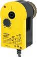
Spring return Combination options with valve VUN/BUN, VUD/BUD, VUE/BUE VUN/BUN, VUD/BUD, VUE/BUE VUG/BUG, VUS/BUS to DN 025 VUG/BUG, VUS/BUS to DN 025
Further information Page 228 Page 230 Page 232 Page 234
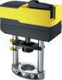
Type designation
Technical data
Spring return
Combination options with valve
VUD/BUD/VQD/BQD, VUE/BUE/VQE/BQE, VUG/BUG VUN/BUN, VUS/BUS, VUP, V6R/B6R
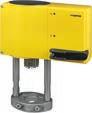
/ (230)
VUD/BUD/VQD/BQD, VUE/BUE/VQE/BQE, VUG/BUG, VUN/BUN, VUS/BUS, VUP, V6R/B6R
Further information Page 236 Page 239 Type
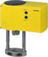
Combination options with valve
VQD/BQD, VQE/BQE, VUG/BUG, VUS/BUS, VUP, V6R/B6R
VQD/BQD, VQE/BQE, VUG/BUG, VUS/BUS, VUP, V6R/B6R
VQE/BQE, VUG/BUG, VUS/BUS, VUP, V6R/B6R
Further information Page 247 Page 254 Page 257
Features
• Activation of 2-way and 3-way valves of the VUN/BUN, VUD/BUD and VUE/BUE series
• For controllers with a switching (2-/3-point) output
• Synchronous motor with electronic control unit and time-dependent cut-off
• Direction of operation can be selected directly on the cable
• Maintenance-free gearbox with magnetic coupling
• Gear unit can be disengaged to position the valve by hand (hexagon key provided)
• Connection with valve spindle performed automatically
• Cap nut for valve fitting made of brass
• Fitting vertically upright to horizontal, not suspended
Technical data
Power supply
Parameters
Ambient conditions
Power supply 24 VAC ±20%, 50...60 Hz
Power supply 230 VAC ±15%, 50...60 Hz
Actuator stroke1)
0...8 mm
Response time 200 ms
Ambient temperature
Media temperature
Function
Construction
Standards, directives
−10...55 °C
Max. 100 °C
Ambient humidity 5...95% rh, no condensation
Control
Weight
Housing
2-/3-point
0.7 kg
Lower section black, upper section yellow
Housing material Flame-retardant plastic
Power cable 1.2 m long, 3 × 0.75 mm²
Type of protection
IP54 (EN 60529), horizontal Protection class 24 V III (EN 60730)
Protection class 230 V II (EN 60730)
CE conformity according toEMC Directive 2014/30/EUEN 61000-6-1, EN 61000-6-2
EN 61000-6-3, EN 61000-6-4
Low-Voltage Directive 2014/35/EUEN 60730-1
EN 60730-2-14
Over-voltage category III
Degree of contamination II
Directive 2006/95/EC EEC (II B)
Machinery Directive 2006/42/EC (according to Appendix II, 1B)

Overview of types Type
1) Stroke 10 mm for AVM115F901
EN ISO 12100:2018
Type
A AVM115F901: For SAUTER Valveco VCL040 and VCL050, inverse scale, inverse connection
Accessories
Type Description
0372145001Auxiliary change-over contacts, single 0372145002Auxiliary change-over contacts, double 0372249001Temperature adapter for AVM1x5(S), AVF12x(S), AVM321(S), media temperature > 100… 130 °C
0372273001Adapter for Siemens valve VVG/VXG 44, 48
0372286001Potentiometer 130 Ω
0372286002Potentiometer 1000 Ω
0372286003Potentiometer, 5000 Ω
0372320001Hexagon key as visualisation for position indicator
A Auxiliary change-over contacts: Infinitely variable 0...100%, admissible load 5(2) A, 24...230 V
A Potentiometers: Only one potentiometer or one set of auxiliary contacts can be fitted for each actuator
AVM1*5SF***
Features
• Activation of 2-way and 3-way valves of the VUN/BUN, VUD/BUD and VUE/BUE series
• For controllers with a switching (2- and 3-point) or continuous (0...10 V) output
• Stepping motor with SAUTER Universal Technology (SUT) electronic control unit and electronic, force-dependent cut-off
• Automatic recognition of applied control signal (continuous or switched)
• Coding switches for selecting characteristic and running time
• Type of characteristic (linear/equal-percentage) can be set on the actuator
• Automatic adaptation to valve stroke
• Maintenance-free gear unit
• Gear unit can be disengaged in order to position the valve by hand (hexagon key provided)
• Connection with valve spindle performed automatically after control voltage is applied
• Brass cap nut for fitting the valve
• Fitting vertically upright to horizontal, not suspended
Technical data
Power supply
Parameters
Positioner
Ambient conditions
Construction
Standards, directives
CE conformity
Power supply 24 VAC ±20%, 50...60 Hz
Power supply 24 VDC -10...20%
Actuator stroke1) 0...8 mm
Response time 200 milliseconds
Control signal 0…10 V, Ri > 100 kΩ
Positional feedback signal 0...10 V, load > 10 kΩ
Starting point U0 0 or 10 V
Control span ΔU 10 V
Switching range Xsh 200 mV
Ambient temperature -10...55 °C
Ambient humidity 5…95% rh, no condensation
Media temperature Max. 100 °C
Weight
Housing
0.7 kg
Lower section black, upper section yellow
Housing material Fire-retardant plastic
Power cable 1.2 m, 5 × 0.75 mm²
Type of protection
IP54 (EN 60529), horizontal Protection class III (IEC 60730)
EMC Directive 2014/30/EUEN 61000-6-1, EN 61000-6-3, EN 61000-6-4

1) Stroke 10 mm for AVM115SF901
Valves, control valves, dampers, actuators | Regulating valves and valve actuators
Type Voltage
AVM105SF13224 V~/= 250 N 35/60/120 s4.8 W, 8.5 VA
AVM115SF13224 V~/= 500 N 60/120 s 4.9 W, 8.7 VA
AVM115SF90124 V~/= 500 N 80/160 s 4.9 W, 8.7 VA
A AVM105SF132, AVM115SF132: Equal-percentage characteristic, can be converted to linear A AVM115SF901: For SAUTER Valveco VCL040 and VCL050, inverse scale, inverse connection
Accessories
Type Description
0313529001Split-range unit for adjusting sequences, fitted in separate junction box
0372145001Auxiliary change-over contacts, single 0372145002Auxiliary change-over contacts, double 0372249001Temperature adapter for AVM1x5(S), AVF12x(S), AVM321(S), media temperature > 100… 130 °C
0372249002Temperature adapter for AVM1x5(S), AVF12x(S), AVM321(S), media temperature > 130… 150 °C
0372273001Adapter for Siemens valve VVG/VXG 44, 48
0372286001Potentiometer 130 Ω
0372286002Potentiometer 1000 Ω
0372286003Potentiometer, 5000 Ω
A Auxiliary change-over contacts: Infinitely variable 0...100%, admissible load 5(2) A, 24...230 V
A Potentiometers: Only one potentiometer or one set of auxiliary contacts can be fitted for each actuator
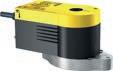
Features
• Actuation of 2- and 3-way valves
• For controllers with a switching (2-/3-point) output
• Synchronous motor with electronic control unit and cut-off
• Maintenance-free gear unit
• Gear unit can be disengaged in order to position the valve by hand with the provided hexagon key (load-free)
• Connection with valve spindle performed semi-automatically
• Fitting vertically upright to horizontal, not suspended
Technical data
Power
Parameters
Ambient conditions
Function
Construction
Standards and directives
Actuator stroke 8...20 mm Response time
Ambient temperature -10...55 °C
Media temperature Max. 100 °C
Ambient humidity 5...85% rh, no condensation
Control 2-/3-point
Weight 1 kg
Housing
Housing material
Lower section black, upper section yellow
Flame-retardant plastic
Power cable 1.2 m long, 3 × 0.75 mm2
Type of protection
IP54 (EN 60529), horizontal Protection class 230 V: II (EN 60730)
CE conformity according toEMC Directive 2014/30/EUEN 61000-6-1, EN 61000-6-2 EN 61000-6-3, EN 61000-6-4
Low-Voltage Directive 2014/35/EUEN 60730-1, EN 60730-2-14
Over-voltage category III
Degree of contamination II
Machinery Directive 2006/42/EC (according to Appendix II, 1B)
EN ISO 12100:2018
Overview

Accessories
Type Description
0510390029Mounting set for SAUTER VDL valves with 15 mm stroke, thread DN 40 and DN 50 for AVM215(S)F***R
0510390030 Mounting set for SAUTER VU*/BU* valves with 8 mm stroke for AVM215(S)F***R
0510390031Mounting set for SAUTER VU*/BU* valves with 20 mm stroke for AVM215(S)F***R
Type Description
0510390032Mounting set for SAUTER V6*/B6* and VX*/BX* valves, thread DN 15 to DN 50 for AVM215(S)F***R
0510390033 Mounting set for IMI TA-Fusion valves, thread DN 32 to DN 50 for AVM215(S)F***R
0510390034Mounting set for IMI TA-Fusion valves, thread DN 65 to DN 80 for AVM215(S)F***R
0510390035Mounting set for IMI CV valves, thread DN 15 to DN 50 for AVM215(S)F***R
0510390036Mounting set for IMI KTM 512 valves, thread DN 15 to DN 50 for AVM215(S)F***R
0510390037Mounting set for IMI KTM 512 valves, thread DN 65 to DN 100 for AVM215(S)F***R
0510390038Mounting set for Frese valves up to 20 mm stroke, flange DN 50 to DN 80 for AVM215(S)F***R
0510390039Mounting set for Danfoss VFS/VL/VF valves: thread DN 15 to DN 50, VEFS2: DN 25 to DN 50 for AVM215(S)F***R
0510390040 Mounting set for Danfoss VRB/VRG valves, thread DN 15 to DN 50 for AVM215(S)F***R
0510390060Adapter set for AVM 2*5 for Schneider V241/V341
0510480003Dual auxiliary switch unit for valve actuators AVM215(S), AVM321(S) with 8 mm stroke
0510480004Dual auxiliary switch unit
0372320001Hexagon key as visualisation for position indicator
A Auxiliary change-over contacts: infinitely variable 0...100%, admissible load 3(1.5) A, 24...230 V
A Accessory 0510390029 can also be used for SAUTER Valveco compact DN 40 and DN 50
AVM215SF132
Features
• Actuation of 2- and 3-way valves
• For controllers with a switching (2- and 3-point) or continuous (0...10 V) output
• Stepping motor with SAUTER Universal Technology (SUT) electronic control unit and electronic, forcedependent cut-off
• Automatic recognition of applied control signal (continuous or switched)
• Coding switches for selecting characteristic and running time
• Type of characteristic (linear/equal-percentage) can be set on the actuator
• Automatic adaptation to valve stroke
• Direction of operation can be selected directly on the cable
• Maintenance-free gear unit
• Gear unit can be disengaged in order to position the valve by hand with the hexagon key provided (loadfree)
• Connection with valve spindle performed semi-automatically after control voltage is applied
• Fitting vertically upright to horizontal, not suspended
Technical data
Power supply
Parameters
Positioner
Ambient conditions
Construction
Power supply 24 VAC ±20%, 50…60 Hz
Power supply 24 VDC −10...20%
Actuator stroke 8...20 mm
Response time 200 milliseconds
Control signal 0...10 V, Ri > 100 kΩ
Positional feedback signal 0...10 V, load > 10 kΩ
Starting point U0 0 or 10 V
Control span ΔU 10 V
Switching range Xsh 200 mV
Ambient temperature
−10…55 °C
Ambient humidity 5…85% rh, no condensation
Media temperature Max. 100 °C
Weight
Housing
Housing material
Standards, directives
1 kg
Lower section black, upper section yellow
Flame-retardant plastic
Power cable 1.2 m, 5 × 0.5 mm2
Type of protection IP54 (EN 60529), horizontal Protection class III (IEC 60730)
CE conformity according toEMC Directive 2014/30/EUEN 61000-6-1, EN 61000-6-3, EN 61000-6-4

Type
N
A AVM215SF132-7 including adapter set for VDL flanged valves DN 50, DN 65 and DN 80
Accessories
Type Description
0510390029Mounting set for SAUTER VDL valves with 15 mm stroke, thread DN 40 and DN 50 for AVM215(S)F***R
0510390030 Mounting set for SAUTER VU*/BU* valves with 8 mm stroke for AVM215(S)F***R
0510390031Mounting set for SAUTER VU*/BU* valves with 20 mm stroke for AVM215(S)F***R
0510390032Mounting set for SAUTER V6*/B6* and VX*/BX* valves, thread DN 15 to DN 50 for AVM215(S)F***R
0510390033Mounting set for IMI TA-Fusion valves, thread DN 32 to DN 50 for AVM215(S)F***R
0510390034Mounting set for IMI TA-Fusion valves, thread DN 65 to DN 80 for AVM215(S)F***R
0510390035Mounting set for IMI CV valves, thread DN 15 to DN 50 for AVM215(S)F***R
0510390036Mounting set for IMI KTM 512 valves, thread DN 15 to DN 50 for AVM215(S)F***R
0510390037Mounting set for IMI KTM 512 valves, thread DN 65 to DN 100 for AVM215(S)F***R
0510390038Mounting set for Frese valves up to 20 mm stroke, flange DN 50 to DN 80 for AVM215(S)F***R
0510390039Mounting set for Danfoss VFS/VL/VF valves: thread DN 15 to DN 50, VEFS2: DN 25 to DN 50 for AVM215(S)F***R
0510390040 Mounting set for Danfoss VRB/VRG valves, thread DN 15 to DN 50 for AVM215(S)F***R
0510390060Adapter set for AVM 2*5 for Schneider V241/V341
0510480003Dual auxiliary switch unit for valve actuators AVM215(S), AVM321(S) with 8 mm stroke
0510480004Dual auxiliary switch unit
0372320001Hexagon key as visualisation for position indicator
A Auxiliary change-over contacts: infinitely variable 0...100%, admissible load 3(1.5) A, 24...230 V
A Accessory 0510390029 can also be used for SAUTER Valveco compact DN 40 and DN 50
Features
• In ventilation air conditioning units1) for actuation of 2- and 3-way valves of type series AVM 321: VUD, VUE, VUN, BUD, BUE, BUN and AVM 322: V6R, VQD, VQE, VUG, VUP, VUS, B6R, BQD, BQE, BUG, BUS
• For controllers with a switching output (2-point or 3-point control)
• Synchronous motor with electronic control unit and load-dependent cut-off
• Direction of operation and running time can be set using coding switches
• Crank handle for external manual adjustment with motor cut-off
• Low operating noise
• Simple assembly onto valve; spindle is automatically connected after nominal voltage is applied
• Numerous adapters enable the unit to be fitted onto non-SAUTER valves
• Electrical parallel operation of five actuators
• Three-piece housing made of flame-retardant yellow/black plastic and seals with type of protection IP54
• Maintenance-free gearbox made of plastic; threaded spindle and gearbox base-plates made of steel
• Patented actuator-valve coupling
• Mounting column made of aluminium
• Fixing bracket made of cast light alloy for valve fitting with 20 mm stroke and made of plastic for valve fitting with 8 mm stroke
• Electrical connections (max. 1.5 mm²) with screw terminals
• Two break-out cable inlets for metric cable gland made of plastic M20 × 1.5
• Fitting vertically upright to horizontal, not suspended
Technical data
Power supply

Parameters
Ambient conditions
Standards, directives
Power supply 24 VAC ±20%, 50...60 Hz
Power supply 24 VDC −10...20%
Power supply 230 VAC ±15%
Power consumption2) < 2.4 W, < 4.0 VA (at nominal voltage, with movement)
Nominal force3) 1000 N
Operating noise4) < 30 dB (A) at nominal force
Response time > 200 ms
Media temperature5) 0...100 °C
Operating temperature −10...55 °C
Storage and transport temperature−40...80 °C
Humidity without condensation5...85% rh
Type of protection IP54 (EN 60529)
Protection class II (EN 60730), III (EN 60730)
1) To be used outside HVAC applications only after consultation with the manufacturer
2) For power consumption in combination with accessory 0500570001, see section “Power consumption at nominal voltage”
3) Actuating power 1000 N under nominal conditions (24 V or 230 V, 25 °C ambient temperature, 50 Hz). With boundary conditions (19.2 V~ / 28.8 V~ / 21. V= / 28.8 V=, -10 °C / 55 °C, 60 Hz) and running time, the actuating/tensile force is minimised to 800 N
4) Operating noise with the slowest running time, measuring distance 1 m
5) At media temperature > 100 °C appropriate accessory must be used (temperature adapter); at media temperature < 0 °C appropriate accessory must be used (stuffing box heater)
CE conformity according toEMC Directive 2014/30/EUEN 61000-6-1, EN 61000-6-2 EN 61000-6-3, EN 61000-6-4
Low-Voltage Directive 2014/35/EUEN 60730-1, EN 60730-2-14 (AVM32*F110 and F120)
Over-voltage categories III
Degree of contamination II
Max. altitude 2000 m
Machinery Directive 2006/42/EC (according to Appendix II, 1B)
EN ISO 12100:2018
Overview of types Type
AVM322F120230 V~20 mm6 (12) s/mm<
AVM322F12224 V~/=20 mm6 (12) s/mm<
AVM321F110230 V~8 mm12 (6) s/mm<
A AVM32*F1*2: CSA-certified actuators on request (only for devices with supply voltage 24 V~/=). Accessory is not CSA-certified.
A Power consumption: at nominal voltage and with movement; for more power consumption data, see table “Power consumption for supply voltage”.
Accessories
AVM 321, 322
Type Description
0500570001Energy module for reset function for valve actuators AVM321S/AVM322S and AVM321F112/AVM322F122
0510600001 Cable module, 1.2 m, 3-wire, PVC
0510600002Cable module, 1.2 m, 3-wire, halogen-free
0510600003Cable module, 1.2 m, 6-wire, PVC
0510600004Cable module, 1.2 m, 6-wire, halogen-free
0510600005Cable module, 5 m, 3-wire, PVC
0510600006Cable module, 5 m, 3-wire, halogen-free
0510600007Cable module, 5 m, 6-wire, PVC
0510600008Cable module, 5 m, 6-wire, halogen-free
AVM 321
Type Description
0372249001Temperature adapter for AVM 321(S), required when temperature of the medium > 100...130 °C (recommended for temperatures < 10 °C) DN 15...50
0372249002Adaptor required when temperature of the medium is 130...150 °C, DN 15...50 0510480003Dual auxiliary switch unit for valve actuators AVM215(S), AVM321(S) with 8 mm stroke
AVM 322
Type Description
0372336180Adaptor for media temperature above 100 °C to 150 °C for AVM322(S) 0372336240Adaptor for media temperature above 130 °C to 200 °C for AVM322(S) 0510240012Mounting set for SAUTER V6** / B6** and VX*/BX* valves with 14 mm stroke for AVM322(S) 0510390006Mounting set for Siemens valves with 20 mm stroke, spindle diameter 10 mm for AVM322(S) 0510390007Mounting set for Johnson Controls valves up to 20 mm stroke for AVM322(S) 0510390008Mounting set for Honeywell valves up to 20 mm stroke for AVM322(S) 0510390009Mounting set for LDM valves up to 20 mm stroke for AVM322(S) 0510390010Mounting set for ITT-Dräger valves up to 20 mm stroke for AVM322(S) Valves,
Valves, control valves, dampers, actuators | Regulating valves and valve actuators
Type Description
0510390012Mounting set for Belimo valves up to 20 mm stroke for AVM322(S)
0510390028Adapter set for non-SAUTER valves (Frese), stroke 20 mm
0510480004Double auxiliary contact
A Accessory is not CSA-certified.
Features
• In ventilation and air conditioning units for actuating 2- and 3-way valves of type series AVM 321S: VUD, VUE, VUN, BUD, BUE, BUN and AVM 322S: V6R, VQD, VQE, VUG, VUP, VUS, B6R, BQD, BQE, BUG, BUS
• For controllers with constant output (0...10 V / 4...20 mA) or switching output (2-point or 3-point control)
• BLDC motor (brushless DC) with SUT (SAUTER Universal Technology) electronic control unit of the third generation and electronic load-dependent cut-off
• Automatic detection of applied control signal (continuous or switching), operating indicator using bi-colour LED
• Automatic adaptation to the stroke of the valve, between 8 and 20 mm
• Low operating noise
• With the built-in absolute distance measurement system, the position is always maintained in the case of power failure
• The direction of operation, characteristic (linear/equal percentage), running time and control signal (voltage/current) can be adjusted via coding switches
• Integrated forced operation can be set via coding switches (with selectable direction of operation)
• Easy re-initialisation using a coding switch
• Crank handle for external manual adjustment with motor cut-off
• Simple assembly onto valve; spindle is automatically connected after control voltage is applied
• Numerous adapters enable the unit to be fitted onto non-SAUTER valves
• Electrical parallel operation of five actuators
• Parameterisation option via the BUS interface
• Three-piece housing made of flame-retardant yellow/black plastic and seals with type of protection IP54
• Maintenance-free gearbox made of plastic; threaded spindle and gearbox base-plates made of steel
• Patented actuator-valve coupling
• Mounting column made of aluminium
• Fixing bracket made of cast light alloy for valve fitting with 20 mm stroke and made of plastic for valve fitting with 8 mm stroke
• Electrical connections (max. 1.5 mm²) with screw terminals
• Two break-out cable inlets for metric cable glands made of plastic M20 × 1.5
• Fitting vertically upright to horizontal, not suspended
• Nominal actuating power 1000 N
Technical data
Power supply
Power supply 24 VAC ±20%, 50...60 Hz
Power supply 24 VDC −10...20%
Power supply 230 VAC ±15%
Power consumption1)
Parameters
< 1.7 W, < 3.5 VA (at nominal voltage, with movement)
Nominal force2) 1000 N
Operating noise3) < 30 dB (A) at nominal force
Response time > 200 ms
1) For power consumption in combination with accessory 0500570001, see section “Power consumption at nominal voltage”
2) Actuating power 1000 N under nominal conditions (24 V, 25 °C ambient temperature, 50 Hz). With boundary conditions (19.2 V~ / 28.8 V~ / 21.6 V= / 28.8 V=, -10 °C / 55 °C, 60 Hz) and running time, the actuating/tensile force is minimised to 800 N
3) Noise level at the slowest running time, measuring distance 1 m

Ambient conditions
Standards, directives
Media temperature4) 0...100 °C
Nominal voltage
Characteristic Linear/equal percentage
Control signal y5) 0...10 V, Ri ≥ 50 kΩ 4...20 mA, Ri ≤ 50 Ω
Positional feedback signal y0 0...10 V, load ≥ 5 kΩ
Starting point U0 0 or 10 V
Starting point I0 4 or 20 mA
Control span ΔU 10 V
Control span ΔI 16 mA
Hysteresis Xsh 160 mV 0.22 mA
Operating temperature −10...55 °C
Storage and transport temperature−40...80 °C
Air humidity without condensation5...85% rh
Type of protection
IP54 (EN 60529)
Protection class III (EN 60730-1), EN 60730-2-14
CE conformity according toEMC Directive 2014/30/EUEN 610000-6-1, EN 610000-6-2, EN 610000-6-3, EN 610000-6-4
Low-Voltage Directive 2014/35/EUEN 60730-1, EN 60730-2-14 (AVM32*F110 and F120)
Over-voltage categories III
Degree of contamination II
Max. altitude 2000 m
Machinery Directive 2006/42/EC (according to Appendix II, 1B) EN ISO 12100:2018
Overview of types
A CSA-certified actuators on request (only for devices with supply voltage 24 V~/=). Accessory is not CSA-certified.
Accessories
AVM 321S, 322S
Type Description
0500570003Constant 230 V module for valve actuators AVM321S and AVM322S
0500420001Split-range unit module for setting sequences for valve actuators AVM321S and AVM322S
05004200024...20 mA feedback module
0500570001Energy module for reset function for valve actuators AVM321S/AVM322S and AVM321F112/AVM322F122
0510600001 Cable module, 1.2 m, 3-wire, PVC
0510600002Cable module, 1.2 m, 3-wire, halogen-free
0510600003Cable module, 1.2 m, 6-wire, PVC
0510600004Cable module, 1.2 m, 6-wire, halogen-free
0510600005Cable module, 5 m, 3-wire, PVC
0510600006Cable module, 5 m, 3-wire, halogen-free
4) At media temperature > 100 °C appropriate accessory must be used (temperature adapter); at media temperature < 0 °C appropriate accessory must be used (stuffing box heater)
5) Positional feedback signal: also for 2- or 3-point, depending on type of connection
Type Description
0510600007Cable module, 5 m, 6-wire, PVC
0510600008Cable module, 5 m, 6-wire, halogen-free
AVM 321S
Type Description
0372249001Temperature adapter for AVM 321(S), required when temperature of the medium > 100...130 °C (recommended for temperatures < 10 °C) DN 15...50
0372249002Adaptor required when temperature of the medium is 130...150 °C, DN 15...50
0510480003Dual auxiliary switch unit for valve actuators AVM215(S), AVM321(S) with 8 mm stroke
AVM 322S
Type Description
0500240001Adaptor for media temperature above 100 °C to 150 °C for AVM322(S)
0500240002Adaptor for media temperature above 130 °C to 200 °C for AVM322(S)
0510240012Mounting set for SAUTER V6** / B6** and VX*/BX* valves with 14 mm stroke for AVM322(S)
0510390006Mounting set for Siemens valves with 20 mm stroke, spindle diameter 10 mm for AVM322(S)
0510390007Mounting set for Johnson Controls valves up to 20 mm stroke for AVM322(S)
0510390008Mounting set for Honeywell valves up to 20 mm stroke for AVM322(S)
0510390009Mounting set for LDM valves up to 20 mm stroke for AVM322(S)
0510390010Mounting set for ITT-Dräger valves up to 20 mm stroke for AVM322(S)
0510390012Mounting set for Belimo valves up to 20 mm stroke for AVM322(S)
0510390028Adapter set for non-SAUTER valves (Frese), stroke 20 mm
0510480004Double auxiliary contact
A Accessory is not CSA-certified.
A The CASE Components configuration tool can be downloaded from the CASE Suite product page (GZS 100, 150) on the SAUTER homepage.
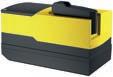
Features
• In ventilation and air conditioning units1) For actuation of 2- and 3-way valves
• For controllers with a switching output (2-point or 3-point control)
• Synchronous motor with electronic control unit and load-dependent cut-off
• Direction of operation and positioning time can be set using coding switches
• Crank handle for external manual adjustment with motor cut-off
• Low operating noise
• Simple assembly onto valve; spindle is automatically connected after nominal voltage is applied
• Numerous adapters enable the unit to be fitted onto non-SAUTER valves
• Electrical parallel operation of five actuators
• Three-piece housing made of flame-retardant yellow/black plastic and seals with type of protection IP54
• Maintenance-free gearbox made of plastic; threaded spindle and gearbox base-plates made of steel
• Patented actuator-valve coupling
• Electrical connections (max. 1.5 mm²) with screw terminals
• Two break-out cable inlets for metric cable gland made of plastic M20 × 1.5
• Fitting position vertically upright to horizontal, not suspended
Technical data
Power supply

Parameters
Ambient conditions
Construction
Standards and directives
Power supply 24 VAC ±20%, 50...60 Hz
Power supply 24 VDC -10...20%
Power supply 230 VAC ±15%
Power consumption2) < 2.4 W, < 4.0 VA (at nominal voltage, with movement)
Nominal force3) 1000 N
Operating noise4) < 30 dB (A) at nominal force
Response time > 200 ms
Media temperature5) 0...100 °C max.
Operating temperature -10...55 °C
Storage and transport temperature-40...80 °C
Humidity without condensation5...85% rh
Dimensions W × H × D 160 × 114 × 88
Weight 0.94
Type of protection IP54 (EN 60529)
Protection class II (EN 60730), III (EN 60730)
1) To be used outside HVAC applications only after consultation with the manufacturer
2) For power consumption in combination with accessory 0500570001, see section “Power consumption at nominal voltage”
3) Actuating power 1000 N under nominal conditions (24 V or 230 V, 25 °C ambient temperature, 50 Hz). With boundary conditions (19.2 V~ / 28.8 V~ / 21.6 V= / 28.8 V=, -10 °C / 55 °C, 60 Hz) and positioning time, the actuating/tensile force is minimised to 800 N
4) Operating noise with the slowest positioning time, measuring distance 1 m
5) At media temperature > 100 °C appropriate accessory must be used (temperature adapter); at media temperature < 0 °C appropriate accessory must be used (stuffing box heater)
CE conformity according toEMC Directive 2014/30/EUEN 61000-6-1, EN 61000-6-2 EN 61000-6-3, EN 61000-6-4
Low-Voltage Directive 2014/35/EUEN 60730-1, EN 60730-2-14 (AVM322F120R)
Over-voltage categories III
Degree of contamination II
Max. altitude 2,000 m
Machinery Directive 2006/42/EC (according to Appendix II, 1B)
EN ISO 12100:2018
Overview of types Type
6 (12) s/mm< 2.4 W, < 4.0 VA AVM322F122R 24 V~/= 20 mm
6 (12) s/mm< 2.4 W, < 4.0 VA
A Power consumption: at nominal voltage and with movement; for more power consumption data, see table “Power consumption for supply voltage”
Accessories
Type Description
0500240001Adaptor for media temperature above 100 °C to 150 °C for AVM322(S)
0500240002Adaptor for media temperature above 130 °C to 200 °C for AVM322(S)
0500570001Energy module for reset function for valve actuators AVM321S/AVM322S and AVM321F112/AVM322F122
0510390020 Mounting set for SAUTER VU*/BU* and VQ*/BQ* valves with 20 mm stroke for AVM322(S)***R
0510390021Mounting set for SAUTER V6*/B6* and VX*/BX* valves with 14 mm stroke for AVM322(S)***R
0510390022Mounting set for Siemens valves with 20 mm stroke, spindle diameter 10 mm for AVM322(S)***R
0510390023Mounting set for Johnson Controls valves up to 20 mm stroke for AVM322(S)***R
0510390024Mounting set for Honeywell valves up to 20 mm stroke for AVM322(S)***R
0510390025Mounting set for LDM valves up to 20 mm stroke for AVM322(S)***R
0510390026Mounting set for ITT-Dräger valves up to 20 mm stroke for AVM322(S)***R
0510390027Mounting set for Belimo valves up to 20 mm stroke for AVM322(S)***R
0510390028Mounting set for Frese valves up to 20 mm stroke, flange DN 50 to DN 80 for AVM322(S)***R
0510390041Mounting set for SAUTER VDL valves with 15 mm stroke, thread DN 40 and DN 50 for AVM322(S)***R
0510390061Mounting set for Schneider V241/V341 valves, DN 15 to DN 50 for AVM322(S)***R
0510480004Dual auxiliary switch unit
Features
• In ventilation and air conditioning units1) For actuation of 2- and 3-way valves
• For controllers with constant output (0...10 V / 4...20 mA) or switching output (2-point or 3-point control)
• BLDC motor (brushless DC) with SUT (SAUTER Universal Technology) electronic control unit of the third generation and electronic load-dependent cut-off
• Automatic detection of applied control signal (continuous or switching), operating indicator using bi-colour LED
• Automatic adaptation to the stroke of the valve, between 8 and 20 mm
• Low operating noise
• With the built-in absolute distance measurement system, the position is always maintained in the case of power failure
• The direction of operation, characteristic (linear/equal percentage), positioning time and control signal (voltage/current) can be adjusted via coding switches
• Integrated forced operation can be set via coding switches (with selectable direction of operation)
• Easy re-initialisation using a coding switch
• Crank handle for external manual adjustment with motor cut-off
• Simple assembly onto valve; spindle is automatically connected after control voltage is applied
• Numerous adapters enable the unit to be fitted onto non-SAUTER valves
• Electrical parallel operation of five actuators
• Parameterisation option via the BUS interface
• Three-piece housing made of flame-retardant yellow/black plastic and seals with type of protection IP54
• Maintenance-free gearbox made of plastic; threaded spindle and gearbox base-plates made of steel
• Patented actuator-valve coupling
• Electrical connections (max. 1.5 mm²) with screw terminals
• Two break-out cable inlets for metric cable glands made of plastic M20 × 1.5
• Fitting position vertically upright to horizontal, not suspended
• Nominal actuating power 1000 N
Technical data
Power supply

Parameters
Power supply 24 VAC ±20%, 50...60 Hz
Power supply 24 VDC -10...20%
Power supply 230 VAC ±15%
Power consumption2) < 1.7 W, < 3.5 VA (at nominal voltage, with movement)
Positioning time (s/mm) 6 (4)
Nominal force3) 1000 N
Nominal stroke 20 mm
Operating noise4) < 30 dB (A) at nominal force
Response time > 200 ms
Media temperature5) 0...100 °C
1) To be used outside HVAC applications only after consultation with the manufacturer
2) For power consumption in combination with accessory 0500570001, see section “Power consumption at nominal voltage”
3) Actuating power 1000 N under nominal conditions (24 V, 25 °C ambient temperature, 50 Hz); With boundary conditions (19.2 V~ / 28.8 V~ / 21.6 V= / 28.8 V=, -10 °C / 55 °C, 60 Hz) and positioning time, the actuating/tensile force is minimised to 800 N
4) Noise level with the slowest positioning time, measuring distance 1m
5) At media temperature > 100 °C appropriate accessory must be used (temperature adapter); at media temperature < 0 °C appropriate accessory must be used (stuffing box heater)
Ambient conditions
Construction
Standards and directives
Nominal voltage 24 V~/=
Characteristic Linear/equal percentage
Control signal y6) 0...10 V, Ri ≥ 50 kΩ 4...20 mA, Ri ≤ 50 Ω
Positional feedback signal y0 0...10 V, load ≥ 5 kΩ
Starting point U0 0 or 10 V
Starting point I0 4 or 20 mA
Control span ΔU 10 V
Control span ΔI 16 mA
Hysteresis Xsh 160 mV 0.22 mA
Operating temperature -10...55 °C
Storage and transport temperature-40...80 °C
Air humidity without condensation5...85% rh
Dimensions W × H × D 160 × 114 × 88 Weight 0.94
Type of protection IP54 (EN 60529)
Protection class II (EN 60730-1), EN 60730-2-14
CE conformity according toEMC Directive 2014/30/EUEN 61000-6-1, EN 61000-6-2 EN 61000-6-3, EN 61000-6-4
Over-voltage categories III
Degree of contamination II
Max. altitude 2,000 m
Machinery Directive 2006/42/EC (according to Appendix II, 1B)
EN ISO 12100:2018
Overview of types
Type
Accessories
Type Description
0500240001Adaptor for media temperature above 100 °C to 150 °C for AVM322(S)
0500240002Adaptor for media temperature above 130 °C to 200 °C for AVM322(S)
0500420001Split-range unit module for setting sequences for valve actuators AVM321S and AVM322S
05004200024…20 mA feedback module for valve actuators AVM321S and AVM322S
0500570001Energy module for reset function for valve actuators AVM321S/AVM322S and AVM321F112/AVM322F122
0500570003 Constant 230 V module for valve actuators AVM321S and AVM322S
0510390020Mounting set for SAUTER VU*/BU* and VQ*/BQ* valves with 20 mm stroke for AVM322(S)***R
0510390021Mounting set for SAUTER V6*/B6* and VX*/BX* valves with 14 mm stroke for AVM322(S)***R
0510390022Mounting set for Siemens valves with 20 mm stroke, spindle diameter 10 mm for AVM322(S)***R
0510390023Mounting set for Johnson Controls valves up to 20 mm stroke for AVM322(S)***R 0510390024Mounting set for Honeywell valves up to 20 mm stroke for AVM322(S)***R
0510390025Mounting set for LDM valves up to 20 mm stroke for AVM322(S)***R 0510390026Mounting set for ITT-Dräger valves up to 20 mm stroke for AVM322(S)***R
0510390027Mounting set for Belimo valves up to 20 mm stroke for AVM322(S)***R 0510390028Mounting set for Frese valves up to 20 mm stroke, flange DN 50 to DN 80 for AVM322(S)***R
6) Positional feedback signal: also for 2- or 3-point, depending on type of connection
Valves, control valves, dampers, actuators | Regulating valves and valve actuators
Type Description
0510390041Mounting set for SAUTER VDL valves with 15 mm stroke, thread DN 40 and DN 50 for AVM322(S)***R
0510390061 Mounting set for Schneider V241/V341 valves, DN 15 to DN 50 for AVM322(S)***R
0510480004Dual auxiliary switch unit
A Accessory is not CSA-certified.
A The CASE Components configuration tool can be downloaded from the CASE Suite product page (GZS 100, 150) on the SAUTER homepage.
Features
• Activation of 2-way and 3-way valves of the VQD/BQD and VQE/BQE series, as well as VUG/BUG, VUS/BUS, VUP, V6R/B6R and VDL
• For controllers with constant output (0...10 V or 4...20 mA) or switching output (2-point or 3-point control)
• Stepping motor with SAUTER Universal Technology (SUT) electronic control unit and electronic, forcedependent cut-off
• Simple assembly with valve; spindle is automatically connected after control voltage is applied (patented system)
• Automatic detection of applied control signal (constant or switched); indicated by two LEDs
• Coding switches for selecting characteristic and running time
• Type of characteristic (linear/quadratic/equal-percentage) can be set on the actuator
• Automatic adaptation to the stroke of the valve (min. valve stroke 8 mm, max. valve stroke 49 mm). The measured stroke is saved and is not lost even in the event of a power failure
• Direction of operation can be selected via screw terminals when making the electrical connection
• Crank handle for external manual adjustment with motor cut-off and as trigger for a re-initialisation
• Numerous adapters enable the unit to be fitted onto non-SAUTER valves
• Power supply 230 V with module or direct connection for 24 VAC / 24 VDC; continuous activation also admissible with 230 V
• Maintenance-free gear unit made of sintered steel; gearbox base-plate made of steel
• Mounting column made of stainless steel; mounting bracket made of cast light alloy for fitting the valve
• Electrical connections (max. 2.5 mm²) with screw terminals
• Three pre-scored cable inlets for M20 × 1.5 (2×) and M16 × 1.5
• Fitting vertically upright to horizontal, not suspended
Technical data
Power supply
Parameters
Positioner
Ambient conditions
Power supply 24 VAC
±20%, 50…60 Hz
Power supply 24 VDC ±15%
Power supply 230 VAC ±15%, 50...60 Hz (with accessories)
Power consumption1)
24 VAC/24 VDC
10 W/20 VA 230 VAC (with accessories)
13 W/28 VA
Running time
2/4/6 s/mm
Actuator stroke 0...49 mm
Response time for 3-point 200 milliseconds
Control signal 1
0...10 V, Ri >100 kΩ
Control signal 2 4...20 mA, Ri = 50 Ω
Positional feedback signal 0...10 V, load > 10 kΩ
Starting point U0 0 or 10 V
Control span ΔU 10 V
Switching range Xsh 300 mV
Ambient temperature −10…55 °C
Ambient humidity < 95% rh, no condensation
Media temperature2) Max. 120 °C
1) Choose transformers for this value, otherwise malfunctions may occur
2) For higher temperatures of the medium (180 °C or 240 °C), use an adapter (see accessories)

Construction
Standards, directives
Weight 4.1 kg
Housing Two-part, yellow
Housing material Flame-retardant plastic
Type of protection
CE/UKCA conformity3)
IP66 (EN 60529)
Protection class III (IEC 60730)
Over-voltage categories III
Degree of contamination III
LVD 2014/35/EU (CE)
EN 60730-1, EN 60730-2-14
EESR-2016 (UKCA) EN 60730-1, EN 60730-2-14
EMC-D 2014/30/EU (CE)EN 61000-6-2, EN 61000-6-4
EMC-2016 (UKCA)4) EN 61000-6-2, EN 61000-6-4
RoHS-D 2011/65/EU & 2015/863/EU (CE)
RoHS-2012 (UKCA)
EN IEC 63000:2018
EN IEC 63000:2018
Overview of types
/ Actuator for valves: VQD/BQD, VQE/BQE, VUG/BUG, VUP, VUS/BUS
/ Actuator with mounting set (see accessories) for valves: V6R, B6R
Type Voltage Actuating powerRunning time Power consumption
AVM234SF13224 VAC/DC2500 N 2/4/6 s/mm10 W, 20 VA
AVM234SF132-524 VAC/DC2500 N 2/4/6 s/mm10 W, 20 VA
AVM234SF132-624 VAC/DC2500 N 2/4/6 s/mm10 W, 20 VA
AVM234SF132-724 VAC/DC1700 N 2/4/6 s/mm10 W, 20 VA
Accessories
Type Description
0313529001Split-range unit for setting sequences
Modules can be added for 2-point/3-point and continuous activation; additional power 2 VA
Type Description
0372332001230 V ±15%, supply voltage
0372332002100 V ±15%, supply voltage
Auxiliary change-over contacts (2 each) 12...250 VAC
Type Description
0372333001Auxiliary change-over contacts (sets of 2), 12...250 VAC, infinitely variable, min. 100 mA and 12 V permissible load 6(2) A
0372333002 Auxiliary change-over contacts (sets of 2), 12...250 VAC, gold-plated contacts, from 1 mA, to max. 30 V, wider range 3(1) A
Potentiometers
Type Description
0372334001Potentiometer, 2000 Ω, 1 W, 24 V
0372334006 Potentiometer, 1000 Ω, 1 W, 24 V
Adapters for high temperatures
Type Description
0372336180Intermediate piece (required when temperature of the medium is 130...180 °C)
0372336240Adapter (required when temperature of the medium is 180...200 °C)
3) Explanation of abbreviations in the “Additional technical information” section of the product data sheet and in the appendix to SAUTER product catalogues 4) EN 61000-6-2: (HF immunity limitation. Feedback signal between 80 MHz and 1000 MHz criterion B, otherwise criterion A)
Mounting set for AVM234SF132 on SAUTER valves (no adapter needed for 0372338 002)
Type Description
0372338001V/B6 to DN 50, V/BXD, V/BXE, to DN 50, stroke 14 mm
0372338002V/B6 DN 65...150, V/BXD, V/BXE from DN 65, stroke 40 mm
0372338003Conversion kit from AV*2*4SF132-5 to standard actuator AV*2*4SF132
0372338004Conversion kit from AV*2*4SF132-6 to standard actuator AV*2*4SF132
Adapter set for non-SAUTER valves
Type Description
0372376010Siemens with 20 mm stroke or 10 mm spindle diameter
0372376014Siemens with 40 mm stroke or 14 mm spindle diameter
0372376015Siemens VXF32, PN 10, DN 100…150; VXF22, PN 6, DN 100
0372377001Johnson Controls DN 15…150, 14, 25, 40 mm stroke, spindle diameter 10, 12, 14 mm
0372378001Honeywell with 20 mm stroke
0372386001LDM type RY113 R/M
0372389001ITT-Dräger, DN 15…32
0372389002ITT-Dräger, DN 40…50
0378263001End stop (needed for V/BXD, V/BXE DN 15…50, V/B6 DN 15 with kvs ≤ 1 m³/h)
0386263001Cable gland M16 × 1.5
0386263002Cable gland M20 × 1.5
0372461001Forced operation for AV×2×4S
0372387001SAUTER Satchwell VZF1727 mounting set
0510390052Adapter set for non-SAUTER valves (Frese), stroke 20 mm
0510390053Adapter set for non-SAUTER valves (Frese), stroke 40/43 mm
A Adapter: Not needed for version AV*2*4SF132-6
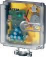
Features
• Activation of 2- and 3-way valves of the VUN/BUN, VUD/BUD and VUE/BUE series, DN 15 to DN 50.
• For controllers with a switching output (3-point control)
• Spring return moves the unit to the end position in the event of a power failure or when a limit controller is activated
• Stepping motor with electronic control unit and electronic, force-dependent cut-off
• Maintenance-free gear unit
• LED display
• Coding switch for changing the running time
• Electrical connections (max. 1.5 mm²) with screw terminals
• Cable inlet M20 × 1.5
• Fitting vertically upright to horizontal, not suspended
Technical data
Power supply
Parameters
Ambient conditions
Construction
Standards and directives
Power supply 230 V~, ±15%, 50...60 Hz
Power consumption 4 W, 7.6 VA
Running time of motor 60/120 s
Running time of spring 18 s ±10
Actuating power 500 N
Actuator stroke 0...8 mm
Response time 200 ms
Ambient temperature 5...60 °C
Media temperature Max. 100 °C
Ambient humidity < 95% rh, no condensation
Weight 2.4 kg
Housing
Lower section black, cover transparent
Housing material Fire-retardant plastic
Materials for gearbox and fitting bracket
Pressure-cast zinc
Type of protection1) IP54 as per EN 60529
Protection class II (IEC 60730)
EMC Directive 2014/30/EUEN 61000-6-1, EN 61000-6-2
EN 61000-6-3, EN 61000-6-4
Low-Voltage Directive 2014/35/EUEN 60730-1, EN 60730-2-14
Over-voltage categories III
Degree of contamination III
Software A (EN 60730)
Mode of operation
Overview of types Type

Type 1 AA (200 ms, EN 60730)
AVF124F130230 V~8 mm 60/120 s4 W, 7.6 VASpindle retracted
AVF124F230230 V~8 mm 60/120 s4 W, 7.6 VASpindle extended
1) Type of protection IP54 only with cable gland
Valves, control valves, dampers, actuators | Regulating valves and
A
AVF124F130: Valve normally closed (NC) with: VUD, BUD, VUE, BUE, VUN, BUN
A AVF124F230: Valve normally open (NO) with: VUD, BUD, VUE, BUE, VUN, BUN
Accessories
Type Description
0370881001Auxiliary change-over contacts, single
0372249001Temperature adapter for AVM1x5(S), AVF12x(S), AVM321(S), media temperature > 100… 130 °C
0372249002Temperature adapter for AVM1x5(S), AVF12x(S), AVM321(S), media temperature > 130… 150 °C
0372460001Cable screw fitting (plastic M20 × 1,5) incl. locking nut and seal
A Auxiliary change-over contacts: Infinitely variable, admissible load 2(1) A, 12...250 V~, min. load 250 mA, 12 V~
AVF125SF132
Features
• Activation of 2-way and 3-way valves of the VUN/BUN, VUD/BUD and VUE/BUE series
• For controllers with switching (2- and 3-point) or continuous output (0…10 V, 4…20 mA)
• Spring return moves the unit to the end position in the event of a power failure or when a limit controller is activated
• Stepping motor with SAUTER Universal Technology (SUT) electronic control unit and electronic, force-dependent cut-off
• Automatic recognition of applied control signal (continuous or switched)
• Coding switches for selecting characteristic and running time
• Type of characteristic (linear/quadratic/equal-percentage) can be set on the actuator
• Direction of operation can be selected via screw terminals when making the electrical connection
• Maintenance-free gear unit
AVF125SF132
• LED display
• Electrical connections (max. 1.5 mm²) with screw terminals
• Cable inlet M20 × 1.5
• Fitting vertically upright to horizontal, not suspended
AVF125SF232
Technical data
Power supply
Power supply
Parameters
Positioner
Ambient
conditions
Construction
24 V~, ±20%, 50...60 Hz
Power consumption 5 W, 8.4 VA
Power consumption on starting1) 30 VA (max. 1 s)
Running time of motor 60/120 s
Running time of spring 18 s ±10
Actuating power 500 N
Actuator stroke 0...8 mm
Control signal 1 0...10 V, Ri = 100 kΩ
Control signal 2 4...20 mA, Ri = 50 Ω
Positional feedback signal 0...10 V; load > 2.5 kΩ
Starting point U0 0 or 10 V
Control span ΔU 10 V
Switching range Xsh 200 mV
Ambient temperature –10...55 °C
Ambient humidity < 95% rh, no condensation
Media temperature Max. 100 °C
Weight
Housing
2.4 kg
Lower section black, cover transparent
Housing material Fire-retardant plastic
Materials for gearbox and fitting bracket
Standards and directives

Pressure-cast zinc
Type of protection2) IP54 as per EN 60529
Protection class III (IEC 60730)
1) Only in the event of a restart or after a spring return
2) Type of protection IP54 only with M20 cable gland
Valves, control valves, dampers, actuators | Regulating valves and valve actuators
EMC Directive 2014/30/EUEN 61000-6-1, EN 61000-6-2 EN 61000-6-3, EN 61000-6-4
Software
Mode of operation
Machinery Directive 2006/42/EC (according to Appendix II, 1B)
A (EN 60730)
Type 1 AA (200 ms, EN 60730)
EN ISO 12100:2018
Overview of types
/ For valves with equal-percentage characteristic; can be changed to linear
Type Voltage Nominal strokeRunning timePower consumptionReset function
AVF125SF13224 V~ 8 mm 60/120 s5 W, 8.4 VASpindle retracted AVF125SF23224 V~ 8 mm 60/120 s5 W, 8.4 VASpindle extended
A AVF125SF132: Actuator spindle normally retracted; valve normally closed (NC) with: VUD, BUD, VUE, BUE, VUN, BUN
A AVF125SF232: Actuator spindle normally extended; valve normally open (NO) with: VUD, BUD, VUE, BUE, VUN, BUN
Accessories
Type Description
0313529001Split-range unit for adjusting sequences, fitted in separate junction box 0370881001Auxiliary change-over contacts, single 0372249001Temperature adapter for AVM1x5(S), AVF12x(S), AVM321(S), media temperature > 100… 130 °C
0372249002Temperature adapter for AVM1x5(S), AVF12x(S), AVM321(S), media temperature > 130… 150 °C
0372460001Cable screw fitting (plastic M20 × 1,5) incl. locking nut and seal
A Auxiliary change-over contacts: Infinitely variable, admissible load 2(1) A, 12...250 V~, min. load 250 mA, 12 V~
AVF234SF132
Features
• Activation of 2-way and 3-way valves of the VQD/BQD, VQE/BQE, VUG/BUG, VUP, VUS/BUS and V6R/B6R series
• For controllers with switching (2- and 3-point) and continuous (0...10 V, 4...20 mA) output
• Spring return moves to end position in the event of a power failure/interruption or when a limit controller is activated
• Stepping motor with SAUTER Universal Technology (SUT) electronic control unit and electronic, forcedependent cut-off
• Simple assembly with valve; spindle is automatically connected after control voltage is applied (patented system)
• Automatic detection of applied control signal (constant or switched); indicated by two LEDs
• Coding switches for selecting characteristic and running time
• Type of characteristic (linear/quadratic/equal-percentage) can be set on the actuator
AVF234SF132
AVF234SF232
• Automatic adaptation to the stroke of the valve (min. valve stroke 8 mm, max. valve stroke 49 mm). The measured stroke is saved and is not lost even in the event of a power failure
• Direction of operation can be selected via screw terminals when making the electrical connection
• Crank handle for external manual adjustment with motor cut-off and as trigger for a re-initialisation
• Numerous adapters enable the unit to be fitted onto non-SAUTER valves
• Power supply 230 V with module or direct connection for 24 VAC or 24 VDC; continuous activation also admissible with 230 V
• Maintenance-free gear unit made of sintered steel; gearbox base-plate made of steel
• Spring pack and mounting column made of stainless steel; mounting bracket made of cast light alloy for valve fitting
• Electrical connections (max. 2.5 mm²) with screw terminals
• Three pre-scored cable inlets for M20 × 1.5 (2×) and M16 × 1.5
• Fitting vertically upright to horizontal, not suspended
Technical data
Power supply
Parameters
ValveDim app

Positioner
Power supply 24 VAC ±20%, 50...60 Hz
Power supply 24 VDC ±15%
Power supply 230 VAC ±15%, 50...60 Hz (with accessories)
Power consumption1) 24 VAC/24 VDC 10 W, 20 VA 230 VAC (with accessories) 13 W/28 VA
Running time of motor 2/4/6 s/mm
Running time of spring2) 15...30 s
Actuating power 2000 N
Response time for 3-point 200 ms
Number of spring returns > 40 000
Control signal 1 0...10 V, Ri = 100 kΩ
Control signal 2 4...20 mA, Ri = 50 Ω
Positional feedback 0...10 V0...10 V, load > 10 kΩ
Starting point U0 0 V or 10 V
Control span ΔU 10 V
Switching range Xsh 300 mV
1) Choose transformers for this value, otherwise malfunctions may occur
2) Return time equates to a stroke of 14...40 mm and does not depend on the set running time
Ambient conditions
Construction
Standards, directives
Ambient temperature
−10...55 °C
Ambient humidity < 95% rh, no condensation
Media temperature3)
Weight
Housing
Housing material
Type of protection
CE/UKCA conformity4)
Max. 130 °C (180 °C or 240 °C with accessories)
5.6 kg
Two-part, yellow
Flame-retardant plastic
IP66 (EN 60529)
Protection class III (IEC 60730)
Over-voltage categories III
Degree of contamination III
LVD 2014/35/EU (CE)
EESR-2016 (UKCA)
EN 60730-1, EN 60730-2-14
EN 60730-1, EN 60730-2-14
EMC-D 2014/30/EU (CE)EN 61000-6-2, EN 61000-6-4
EMC-2016 (UKCA)5)
RoHS-D 2011/65/EU & 2015/863/EU (CE)
RoHS-2012 (UKCA)
EN 61000-6-2, EN 61000-6-4
EN IEC 63000:2018
EN IEC 63000:2018
Overview of types
Type Voltage Stroke Direction of operation of spring
AVF234SF13224 VAC/DC 14...40 mm
Spindle retracted AVF234SF132-524 VAC/DC 14 mm
AVF234SF23224 VAC/DC 0...40 mm
Spindle retracted
Spindle extended
A AVF234SF132: Valve normally closed (NC) with: VQD/BQD, VQE/BQE, VUG/BUG, BUS; valve normally open (NO) with: VUS, VUP
A AVF234SF132-5: Valve normally closed (NC) with: V6R, B6R
A AVF234SF232: Valve normally open (NO) with: VQD/BQD, VQE/BQE, VUG/BUG, BUS; valve normally closed (NC) with: VUS, VUP
Accessories
Type Description
0313529001Split-range unit for setting sequences
Modules can be added for 2-point/3-point and continuous activation; additional power 2 VA
Type Description
0372332001230 V ±15%, supply voltage
0372332002100 V ±15%, supply voltage
Auxiliary change-over contacts (2 each) 12...250 VAC
Type Description
0372333001Auxiliary change-over contacts (sets of 2), 12...250 VAC, infinitely variable, min. 100 mA and 12 V permissible load 6(2) A
0372333002 Auxiliary change-over contacts (sets of 2), 12...250 VAC, gold-plated contacts, from 1 mA, to max. 30 V, wider range 3(1) A
Potentiometers
Type Description
0372334001Potentiometer, 2000 Ω, 1 W, 24 V
0372334006 Potentiometer, 1000 Ω, 1 W, 24 V
3) An adapter is needed for higher temperatures (180 °C or 240 °C) (see accessories)
4) Explanation of abbreviations in “Additional technical data” section
5) EN 61000-6-2: HF immunity, limitation of feedback signal between 80 MHz and 1000 MHz criterion B, otherwise criterion A
Adapters for high temperatures
Type Description
0372336180Intermediate piece (required when temperature of the medium is 130...180 °C)
0372336240Adapter (required when temperature of the medium is 180...200 °C)
Mounting set for AVF234SF*32 onto SAUTER valves (no adapter needed for 0372338 002)
Type Description
0372338001V/B6 to DN 50, V/BXD, V/BXE, to DN 50, stroke 14 mm
0372338002V/B6 DN 65...150, V/BXD, V/BXE from DN 65, stroke 40 mm
0372338003Conversion kit from AV*2*4SF132-5 to standard actuator AV*2*4SF132
0372338004Conversion kit from AV*2*4SF132-6 to standard actuator AV*2*4SF132
Adapter set for non-SAUTER valves
Type Description
0372376010Siemens with 20 mm stroke or 10 mm spindle diameter
0372376014Siemens with 40 mm stroke or 14 mm spindle diameter
0372376015Siemens VXF32, PN 10, DN 100…150; VXF22, PN 6, DN 100
0372377001Johnson Controls DN 15…150, 14, 25, 40 mm stroke, spindle diameter 10, 12, 14 mm
0372378001Honeywell with 20 mm stroke
0372386001LDM type RY113 R/M
0372389001ITT-Dräger, DN 15…32
0372389002ITT-Dräger, DN 40…50
0378263001End stop (needed for V/BXD, V/BXE DN 15…50, V/B6 DN 15 with kvs ≤ 1 m³/h)
0386263001Cable gland M16 × 1.5
0386263002Cable gland M20 × 1.5
0372387001SAUTER Satchwell VZF1727 mounting set
0372461001Forced operation for AV×2×4S
0510390052Adapter set for non-SAUTER valves (Frese), stroke 20 mm
0510390053Adapter set for non-SAUTER valves (Frese), stroke 40/43 mm
A Adapter: Not needed for version AV*2*4SF132-6
A Potentiometer 130 Ω: This potentiometer must only be used as a voltage divider.
Features
• Combination with VUG and BUG flanged valves
• AVN224SF232 with safety function (as per DIN EN 14597) in combination with VUP flanged valve and normally closed (NC) version
• Actuating power 1100 N
• For controllers with constant output (0...10 V or 4...20 mA) and switching output (2-point or 3-point control)
• Stepping motor with SAUTER Universal Technology (SUT) electronic control unit and electronic, forcedependent cut-off
• Simple assembly with valve; spindle is automatically connected after control voltage is applied (patented system)
• Control signals (constant or switching) are automatically detected and indicated via two LEDs
• Coding switches for selecting characteristic and running time
• Type of characteristic curve (linear/quadratic/equal-percentage) can be set on the actuator
• Automatic stroke adaptation (valve stroke 8…49 mm). Saved stroke is not lost even in the event of power failure
• Direction of operation can be selected via screw terminals when making the electrical connection
• Push-buttons on outside of housing for manual adjustment with motor cut-off and as trigger for reinitialisation
• Can be combined with valves from various manufacturers with optional adapter accessories
• Maintenance-free gear unit made of sintered steel; gearbox base-plate made of steel
• Spring pack and mounting column made of stainless steel; mounting bracket made of cast light alloy for valve fitting
• AVN224SF232 with TÜV certification
• Three break-out cable inlets
The following features and certifications do not apply to the United Kingdom of Great Britain and Northern Ireland (UK):
• AVN224SF232 in combination with VUP
• TÜV certification
The product is not designed for use in the United Kingdom.
Technical data
Power supply
Parameters
Positioner
1) Spring return time equates to a stroke of 14...40 mm and does not depend on the set running time Valves, control valves, dampers,
AVN224SF132
AVN224SF132
AVN224SF232
Power supply 24 VAC ±20%, 50…60 Hz
Power supply 24 VDC ±15%
Power supply 230 VAC ±15%, 50...60 Hz (with accessories)
Power consumption 10 W/18 VA at 24 VAC/DC 11 W/24VA at 230 VAC (with accessories)
Running time of motor 2/4/6 s/mm
Running time of spring1) 15...30 s
Actuating power 1100 N
Number of spring returns > 40 000
Response time for 3-point 200 ms
Control signal 1 0…10 V, Ri = 100 kΩ
Control signal 2 4…20 mA, Ri = 50 Ω
Positional feedback signal 0...10 V, load > 10 kΩ
Starting point U0 0 V or 10 V
Control span ΔU 10 V
ValveDim app

Ambient conditions
Construction
Standards, directives
Switching range Xsh 300 mV
Ambient temperature
−10…55°C
Ambient humidity < 95% rh, no condensation
Media temperature
Housing
Housing material
Cable inlet
Connection terminals
Max. 130°C
Two-part, yellow
Flame-retardant plastic
2 pcs. M20 × 1.5
1 pc. M16 × 1.5
Screw terminals, max. 2.5 mm²
Dimensions W × H × D 230 × 289/382 × 133 mm (height depends on type)
Weight 5.6 kg
Type of protection
IP66 (EN 60529)
Protection class III (IEC 60730)
Over-voltage categories III
Degree of contamination III
CE conformity according to EMC Directive 2014/30/EU2) EN 61000-6-2, EN 61000-6-4
Low-Voltage Directive 2014/35/EUEN 60730-1, EN 60730-2-14
PED 2014/68/EU, cat. IV3) Category IV, fluid group II, liquid or steam pressure
Modules B+D
Overview of types
Type Voltage Direction of operation of spring Certification
AVN224SF13224 VAC/DCSpindle retracted
AVN224SF132-524 VAC/DCSpindle retracted
AVN224SF132-624 VAC/DCSpindle retracted
AVN224SF23224 VAC/DCSpindle extended TÜV
A AVN224SF132: valve normally closed (NC) with VUG and BUG; valve normally open (NO) with VUP
A AVN224SF232: valve normally open (NO) with VUG and BUG; valve normally closed (NC) with VUP (as per DIN EN 14597)
Accessories
Type Description
0313529001Split-range unit for setting sequences
Modules can be added for 2-point/3-point and continuous control; additional power 2 VA
Type
Description
0372332001230 V ±15%, supply voltage
0372332002100 V ±15%, supply voltage
Auxiliary change-over contacts (2 each) 12...250 VAC
Type
Description
0372333001Auxiliary change-over contacts (sets of 2), 12...250 VAC, infinitely variable, min. 100 mA and 12 V permissible load 6(2) A
0372333002 Auxiliary change-over contacts (sets of 2), 12...250 VAC, gold-plated contacts, from 1 mA, to max. 30 V, wider range 3(1) A
2) EN 61000-6-2: HF immunity, limitation of feedback signal between 80 MHz and 1000 MHz criterion B, otherwise criterion A
3) Only AVN224SF232 in combination with VUP flanged valve. See product data sheet for valve
Potentiometer
Type Description
0372334001Potentiometer, 2000 Ω, 1 W, 24 V
0372334006Potentiometer, 1000 Ω, 1 W, 24 V
Adapters for high temperatures
Type Description
0372336180Intermediate piece (required when temperature of the medium is 130...180 °C)
0372336240Adapter (required when temperature of the medium is 180...200 °C)
Mounting set for AVN224SF*32 onto SAUTER valves (no adapter needed for 0372338002)
Type Description
0372338001V/B6 to DN 50, V/BXD, V/BXE, to DN 50, stroke 14 mm
0372338002V/B6 DN 65...150, V/BXD, V/BXE from DN 65, stroke 40 mm
0372338003Conversion kit from AV*2*4SF132-5 to standard actuator AV*2*4SF132
0372338004Conversion kit from AV*2*4SF132-6 to standard actuator AV*2*4SF132
Adapter set for non-SAUTER valves
Type Description
0372376010Siemens with 20 mm stroke or 10 mm spindle diameter
0372376014Siemens with 40 mm stroke or 14 mm spindle diameter
0372377001Johnson Controls DN 15…150, 14, 25, 40 mm stroke, spindle diameter 10, 12, 14 mm
0372378001Honeywell with 20 mm stroke
0372386001LDM type RY113 R/M
0372389001ITT-Dräger, DN 15…32
0372389002ITT-Dräger, DN 40…50
0378263001End stop (needed for V/BXD, V/BXE DN 15…50, V/B6 DN 15 with kvs ≤ 1 m³/h)
0386263001Cable gland M16 × 1.5
0386263002Cable gland M20 × 1.5
0372387001SAUTER Satchwell VZF1727 mounting set
0372461001Forced operation for AVx2xS
0510390052Adapter set for non-SAUTER valves (Frese), stroke 20 mm
0510390053Adapter set for non-SAUTER valves (Frese), stroke 40/43 mm
A Adapter: Not needed for version AVN224SF132-6
A Potentiometer 130 Ω: This potentiometer must only be used as a voltage divider
The automatic hydronic balancing of water distribution networks using dynamic SAUTER valves provides correct supply to air-conditioning, cooling and heating devices. These include fan coil units, chilled ceilings, central underfloor heating systems, remote heating, air recirculation devices and plant segments. SAUTER Valveco and eValveco prevent under- or oversupply and the resulting temperature variations caused by pressure changes in the distribution network.
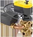
Application
Preheater for ventilation / air-conditioning, cooler
Chilled ceiling, underfloor heating
Static heating
District heating
Version
2-way
3-way
6-way
Female thread
Male thread
Further
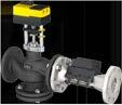
Type designation
Application
Preheater for ventilation / air-conditioning, cooler
Chilled ceiling, underfloor heating
Static heating
District heating
Version
2-way
3-way 6-way
Female thread
Male thread
Flange
Temperature measurement Electronic control
Nominal pressure
Combination options with actuator
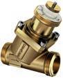
VDL 010…032 Valveco compact
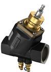
VDL 040, 050 Valveco compact

VDL 050…100 Valveco flange
AXM 217(S)
AXT 301, 311, AXS 315S AXF 217S, AVM 215(S)
AXM 217(S)
AXT 301, 311, AXS 315S AXF 217S, AVM 215(S)
AVM 215, AVM 234
Further information Page 267 Page 267 Page 272
UVC106MF0*5
UVC106BF0*5
Features
• Patented pressure-independent, variable flow control (EP 2307938)
• Integrated flow measurement with feedback
• Easy integration into every building management system
• Variable flow rate setpoint for heating and cooling modes
• For climate ceilings with changeover (4-pipe)
• Integration into the building management system via BACnet MS/TP or Modbus/RTU with RS-485 interface
Technical data
Electronic power supply
Power supply
Parameters
24 VAC, ±20%, 50 Hz
Rated power during continuous operation 3 W (4 VA)
Power consumption when idle1.5 W (2 VA)
Peak inrush current 5 A [3 ms]
Input signal Xs: 0…10 VDC (0.17 mA), split-range 0.5…4.5 VDC heating
5.5…9.5 VDC cooling Ri ≥ 60 kΩ
Feedback signal1) Xi: 0…10 VDC (max. 2 mA)
Feedback signal resolution Approx. 100 mV
Setpoint adjustment
Type of sensor
Analogue (Y1) or via Modbus/RTU or BACnet MS/TP
TTM ultrasonic sensor, no moving parts
Unit of measurement2) [m3/h], l/s, l/min, gpm (UK), gpm (US)
Measuring accuracy ±3% of actual value
Minimum controllable flow3) 3 l/h
Readiness for operation 3…5 minutes after switching on Valve and actuator
Nominal pressure PN16
Differential pressure ∆p4) Max. 2 bar (200 kPa)
Medium5)
Water (glycol-free)
Media temperature 5…90 °C
Leakage rate in % of Kvs 0.001 %
Control characteristic
Interfaces, communication
BMS integration

Equal-percentage (factory setting) or linear
Operating noise (unloaded)6) < 30 dB (A)
Interface
STP cable, 1 × 2-wire, twisted
Protocol Modbus/RTU, slave (MF) or BACnet MS/TP (BF)
Connection7) RS-485, 2-wire, twisted (with shared lead)
Cable type
1) In relation to the measured actual flow.
2) Unit in [ ]: Factory setting
3) In relation to the measured actual flow
4) No minimum differential pressure required
5) In accordance with VDI 2035 sheet 2
6) Measuring distance 1 m, actuator not under load
7) Not electrically isolated
Shielded 2-core cable, STP or FTP
Construction
Baud rate8)
Terminating resistor
Power cable
Housing material
Connection
Ambient conditions
Standards and directives
Ambient temperature
Storage temperature
Ambient humidity
Type of protection9)
9600, 19200, 38400 baud
At both ends 120 Ω
PVC cable, 7 × 0.5 mm2 (length 1 m)
Flow sensor: ABS
Actuator: Flame retardant plastic
6-way ball valve: CW617N
Flow meter: CW617N
DN 15
ISO228/1: 5 × G½" + 1 × G¾" (male thread)
DN 25
ISO228/1: 6 × G1" (male thread)
10…45 °C
-20…50 °C
Max. 85% rh, non-condensing
IP54 (EN 60529), horizontal CE conformity according toEMC Directive 2014/30/EUEN 61000-6-1 (2007)
EN 61000-6-3 (2007) (A1: 2011 / AC: 2012)
Overview of types
DN 15
PED 2014/68/EU
control valve with 6-way ball valve, DN 25
Fluid group II, no CE label (Art. 4.3)
Accessories
Type Description
0560284015Screw fitting in brass, flat-sealing, female thread/male thread for DN 15
0560284025Screw fitting in brass, flat-sealing, female thread/male thread for DN 25
0560332015Strainer in gun metal (bronze), −10…150 °C, mesh aperture 0.5 mm, DN 15 0560332025Strainer in gun metal (bronze), −10…150 °C, mesh aperture 0.8 mm, DN 25
8) Factory setting: 38400 baud, 8 data bits, even parity, 1 stop bit
9) See fitting instructions P100017045
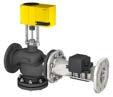
Features
• Patented pressure-independent variable flow control
• Dynamic hydronic balancing at full and partial load
• Integrated flow measurement with feedback and temperature measurement
• Energy monitoring
• Remote commissioning and troubleshooting
• Bluetooth interface for commissioning and maintenance via smartphone app
• Available as 2-way globe valve, version DN 65...DN 100
Technical data
Power supply
Parameters
Volume flow control
Power supply 24 VAC ±10%, 50 Hz
Power supply 24 VDC ±10%
Power consumption
DN 65: 6.5 W / 8 VA
DN 80: 9.5 W / 11 VA
DN 100: 13.5 W / 19 VA
Power consumption when idleDN 65: 5.5 W / 6 VA
DN 80: 8.5 W / 9 VA
DN 100: 8.5 W / 9 VA
Input signal
Y1: 0…10 V= (0.17 mA)
Ri ≥ 60 kΩ
Feedback signal1) X1: 0…10 V= (max. 2 mA)
Additional sensor input
Y2: 0…10 V= (0.17 mA)
Feedback signal resolution Approx. 100 mV
Setpoint adjustment2)
Type of sensor
Valve
Analogue (Y1) or via Modbus RTU (can be switched to BACnet MS/TP)
TTM ultrasonic sensor, no moving parts
Unit of measurement3) [m3/h], l/s, l/min, gpm (UK)
Readiness for operation 5…10 min. after switching on
Control characteristic4) [Equal percentage] or linear
Control accuracy 5% of setpoint
Measuring accuracy ±3% (in relation to the measured actual flow)
Actuator running time 4 s/mm
Nominal pressure
Medium
Media quality
PN 16 (16 bar)
Water (glycol-free)
According to VDI 2035
Media temperature5) 5…130 °C
Leakage rate
Temperature sensor
Interfaces, communication

1) In relation to the measured actual flow
2) In relation to the measured actual flow
3) Factory setting in [ ]
4) Factory setting in [ ]
Type of sensor
Class III as per DIN EN 60534-4 (0.001 × kvs)
2 × Pt1000 as per EN 60751, class B
Cable length 2 m per sensor
Wireless
Bluetooth (max. range 10 m)
5) For media temperatures above 100 °C, use temperature adapter (DN 65 and DN 80).
Electric wiring (incl. bus connection)
Protocol
PVC cable, 7 × 0.5 mm2 , cable length 2 m
Modbus RTU/TCP, slave BACnet MS/TP, slave
Connection6) RS-485 twisted pair cable with shared lead
Cable type
Shielded 2-core cable, STP or FTP Baud rate7)
9600, 19 200 or [38 400]
1 start bit
Parity [even]/odd/no parity
8 data bits
1 stop bit
Topology
Terminating resistor
Indicator/display
Construction
Multi-drop bus, max. length 1000 m
At both ends 120 Ω
Status LEDs
Material of water-bearing partsBrass, bronze, EPDM, stainless steel (1.4401, 1.4122,1.4301), thermoplastic, ceramic
Material of flow meter housingSteel, polypropylene
Material of actuator housingFlame-retardant plastic
Connections
Ambient conditions
Standards, directives
PN16, flange as per EN 1092-2 type 21
Operating temperature 10…45 °C
Storage and transport temperature−20…50 °C
Air humidity 5…85% rh (non-condensing)
Maintenance / calibration
Maintenance-free / factory calibrated Max. altitude 2000 m above sea level
Type of protection
IP54 (EN 60529), horizontal Protection class III
CE conformity according toMeasuring Instruments Directive 2014/32/EU
EN 1434-4:2007
EMC Directive 2014/30/EUVolume flow sensor:
EN 61000-3-2, EN 61000-3-3
EN 61000-6-1, EN 61000-6-3
AVM234:
EN 61000-6-2, EN 61000-6-4 AVM322:
EN 61000-6-1, EN 61000-6-2 EN 61000-6-3, EN 61000-6-4
PED 2014/68/EU
Fluid group II, no CE label
Low-Voltage Directive 2014/35/EUAVM 322 and AVM 234
EN 60730-1, EN 60730-2-14
Pressure and temperature dataEN 764, EN 1333
Flow parameter
EN 60534
Overview of types Type
UVC102MF065DN 650.175…48.8 m³/h26.7 m³/h48.8 m³/h37.4 kg
UVC102MF080DN 800.280…70.7 m³/h38.7 m³/h70.7 m³/h46.1 kg
UVC102MF100DN 1000.420…118.7 m³/h65 m³/h118.7 m³/h69.5 kg
6) Not electrically isolated
7) Standard factory setting in [ ]
Accessories
UVC102MF065, UVC102MF080
Type Description
0510480004Dual auxiliary switch unit
0500240001Adaptor for media temperature above 100 °C to 150 °C for AVM322(S)
0378369101Complete replacement stuffing box for DN 65...150
UVC102MF100
Type Description
0372333001Auxiliary change-over contacts (sets of 2), 12...250 VAC, infinitely variable, min. 100 mA and 12 V permissible load 6(2) A
0372333002 Auxiliary change-over contacts (sets of 2), 12...250 VAC, gold-plated contacts, from 1 mA, to max. 30 V, wider range 3(1) A
0378369101Complete replacement stuffing box for DN 65...150
Flow rate
UVC102MF065 6548.80.17510.915.421.826.748.8
UVC102MF0808070.70.28015.822.331.638.770.7
UVC102MF100100118.70.42026.537.553.065.0118.7
ΔpMaximum closing pressure
VMin Minimum controllable flow
Kvs Actual flow rate with valve fully open and 1 bar (100 kPa) pressure difference
V5 Flow range at Δp 5 kPa
V10 Flow range at Δp 10 kPa
V20 Flow range at Δp 20 kPa
V30 Flow range at Δp 30 kPa
VMax Maximum controllable flow. The maximum flow is reached at a differential pressure of 1 bar (100 kPa). The target flow can be set to a value that is equal to or less than the maximum flow
Features
• Dynamic volume flow control in closed water circuits in conjunction with AXF 217S, AXM 217(S), AXS 315S and AXT 301, 311 actuators for unit valves
• Volume flow range 30…11,500 l/h
• Simple presetting of maximum required volume flow
• Automatic flow regulation
• Versions with and without pressure measurement nipple
• The valve is closed when the spindle is moved in
• Closes against the pressure
• Differential pressure across the control unit is kept constant; valve authority 1
• Slight adaptation of the proven SAUTER actuator technology
• VDL 010…032: Valve with male thread, flat-sealing.
Valve body and plug made of dezincification-resistant (DZR) brass
• VDL 040 and 050: Valve with female thread.
Valve body made of cast iron with spheroidal graphite (GJS-400)
• Spindle made of stainless steel
• Media temperature range: 0…120°C
Technical data
Parameters
Nominal pressure
Operating pressure
Operating temperature
Ambient conditions
Standards, directives
Overview of types
PN 25
Max. 25 bar (up to 120 °C)
0…120 °C
Valve characteristic Linear Leakage rate
0.01%
Operating temperature at valveMax. 100 °C in combination with AXF 217S, AXM 217(S), AVM 215(S), AXS 315S and AXT 301, 311
Pressure and temperature dataEN 764, EN 1333
Flow parameter
PED 2014/68/EU
VDL010F2101030...20014...8002.5G½"
VDL010F2111030...20014...8002.5G½"
VDL015F200H15220...13308...8005G¾"
VDL015F20115100...57514...8002.5G¾"
VDL015F2101565...37014...8005G¾"
EN 60534, page 3
Fluid group II
DN 10…DN 40: no CE label (article 4.3)
DN 50: with CE label (category I)

VDL015F201H15220...13308...8005G¾" B•0.47
VDL015F2111565...37014...8005G¾" B•0.47
VDL015F2201530...20014...8002.5G¾" B−0.38
VDL015F2211530...20014...8002.5G¾" B•0.47
VDL020F20020220...133015...8005G1" B−0.4
VDL020F20120220...133015...8005G1" B•0.5
VDL020F21020160...99015...8004G1" B−0.4
VDL020F210H20300...18008...8005.5G1" B−0.4
VDL020F21120160...99015...8004G1" B•0.5
VDL020F211H20300...18008...8005.5G1" B•0.5
VDL020F22020100...57514...8002.5G1" B−0.4 VDL020F22120100...57514...8002.5G1" B•0.5 VDL025F20025600...36098...8005.5G1¼" B−1.02
VDL025F20125600...36098...8005.5G1¼" B•1.12
VDL025F21025280...18008...8005.5G1¼" B−0.51
VDL025F21125280...18008...8005.5G1¼" B•0.62
VDL032F20032550...40018...8005.5G1½" B−1.17
VDL032F20132550...40018...8005.5G1½" B•1.27
VDL040F201401370...95008...80015G1½" B•3.28
VDL050F201501400...11,5008...80015G2" B•3.71
A DN 10...DN 32 valves with male thread
DN 40 and DN 50 valves with female thread
Accessories
Type Description
0378133010Threaded sleeve, R⅜, flat-sealing, with cap nut and flat seal, G½ - R⅜ 0378133015Threaded sleeve, R½, flat-sealing, with cap nut and flat seal, G¾ - R½ 0378133020Threaded sleeve, R¾, flat-sealing, with cap nut and flat seal, G1 - R¾ 0378134010Solder nipple, Ø 12, flat-sealing, with cap nut and flat seal, G½ 0378134015Solder nipple, Ø 15, flat-sealing, with cap nut and flat seal, G¾ 0378134020Solder nipple, Ø 22, flat-sealing, with cap nut and flat seal, G1 0361951015Screw fitting for male thread with flat seal, G1 - Rp½ 0361951020Screw fitting for male thread with flat seal, G1¼ - Rp¾ 0361951025Screw fitting for male thread with flat seal, G1½ - Rp1
0360391040Screw fitting incl. seal, 2 pcs. required, Rp1½ - G1½ 0360391050Screw fitting incl. seal, 2 pcs. required, Rp2 - G2
0510390029Mounting set for SAUTER VDL valves with 15 mm stroke, thread DN 40 and DN 50 for AVM215(S)F***R
0560332015Strainer in gun metal (bronze), −10…150 °C, mesh aperture 0.5 mm, DN 15
0560332020Strainer in gun metal, –10…150 °C, mesh aperture 0.8 mm, DN 20
0560332025Strainer in gun metal (bronze), −10…150 °C, mesh aperture 0.8 mm, DN 25
0560332032Strainer in gun metal, –10…150 °C, mesh aperture 0.8 mm, DN 32
0560332040Strainer in gun metal, –10…150 °C, mesh aperture 0.8 mm, DN 40
0560332050Strainer in gun metal, –10…150 °C, mesh aperture 0.8 mm, DN 50
Combination of VDL with electric actuators
/ Warranty:The technical data and pressure differences indicated here are applicable only in combination with SAUTER valve actuators. Any warranty will be invalidated if used with valve actuators from other manufacturers.
/ Definitionof∆ps:Maximum admissible pressure drop in the event of a malfunction (pipe break after the valve) at which the actuator reliably closes the valve by means of a return spring.
/ Definitionof∆pmax:Maximum admissible pressure drop in control mode at which the actuator reliably opens and closes the valve.
Pressure differences with motorised actuators
ActuatorAXF217SF404
AXF217SF405
AXM217SF402
AXM217SF404
Page 169
Voltage24 VAC/DC
Control signal 0/2…10 V, 0…5 V, 5…10 V, 0/4…20 mA
Running
Closes against the pressure
VDL010F200
VDL010F201
VDL010F210
VDL010F211
VDL015F200
VDL015F200H
VDL015F201
VDL015F210
VDL015F201H
VDL015F211
VDL015F220
VDL015F221
VDL020F200
VDL020F201
VDL020F210
VDL020F210H
VDL020F211
VDL020F211H
VDL020F220
VDL020F221
VDL025F210
VDL025F211
VDL025F200
VDL025F201
VDL032F200
VDL032F201
Cannot be used to close with the pressure
ActuatorAVM215F120R
AVM215SF132R Page 232 235
Voltage230 VAC
Control signal2-/3-pt.
Running
Closes against the pressure
VDL040F201
VDL050F201
Cannot be used to close with the pressure
/ In combination with AXT301HF110, the following valves only open up to approx. 60%, including a closing safety tolerance of 0.8 mm: VDL010F20*, VDL015F21*, VDL015F20*H, VDL020F20*, VDL020F21*, VDL020F21*H, VDL025F20*, VDL025F21*, VDL032F20* / VDL with valve stroke ≥ 5 mm in combination with AXT 301 require adapter VA 41 (accessory 0550389K010/set of 5).
Pressure differences with thermal actuators
ActuatorAXT301F100
Page
Voltage230 VAC
Control signal2-point
Closes against the pressure
VDL010F200
VDL010F201
VDL010F210
VDL010F211
VDL015F200
VDL015F200H
VDL015F201
VDL015F210
VDL015F201H
VDL015F211
VDL015F220
VDL015F221
VDL020F200
VDL020F201
VDL020F210
VDL020F210H
VDL020F211
VDL020F211H
VDL020F220
VDL020F221
VDL025F210
VDL025F211
VDL025F200
VDL025F201 VDL032F200
8.06.08.06.08.06.08.06.0
VDL032F201 8.08.08.08.08.06.08.06.0
Cannot be used to close with the pressure
/ In combination with AXT311F11*, the white spindle extension must be removed from the following valves before fitting: VDL010F20*, VDL015F21*, VDL015F20*H, VDL020F20*, VDL020F21*H, VDL025F20*, VDL025F21*, VDL032F20*
Pressure differences with thermal continuous actuators
ActuatorAXS315SF102AXS315SF202AXT311F110AXT311F112
Control signal0…10 V
Closes against the pressure
VDL010F200
VDL010F201
VDL010F210
VDL010F211
VDL015F200
VDL015F200H
VDL015F201
VDL015F210
VDL015F201H
VDL015F211
VDL015F220
VDL015F221
VDL020F200
VDL020F201
VDL020F210
VDL020F210H
VDL020F211
VDL020F211H
VDL020F220
VDL020F221
VDL025F210
VDL025F211
VDL025F200
VDL025F201
VDL032F200
VDL032F201
Cannot be used to close with the pressure
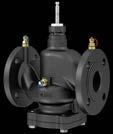
ValveDim app
2) No special valve test required at operating temperature ≤ 110 °C. This also applies to valves with PS x DN < 1000. In both cases, the valves do not have a CE label Valves, control valves,

Features
• Regulating valve with three functions: Control, preset maximum volume flow, automatic flow regulation
• Control of low and mean temperature domestic hot water, cooled water, water with anti-freeze in closed circuits1)
• Volume flow range: 3.7…90.9 m3/h
• Easy to preset the max. required volume flow
• All types with three pressure measurement nipples
• The valve is closed when the spindle is moved in
• Closing procedure against the pressure
• Simple connection to SAUTER actuators AVM 215 for DN 50...80 and AVM 234 for DN 100
• Regulating valve with flange connection (DN 50...DN 100) according to EN ISO 7005-2
• Flat-sealing regulating valve
• Differential pressure across the control unit is kept constant; valve authority 1
• Valve body DN 50…80 made of grey cast iron (GJL‑250); DN 100 made of ductile cast iron (GJS‑400)
• Stainless-steel spindle
Technical data
Parameters
Nominal pressure 16 bar
Volume flow setting range 3.7...90.9 m3/h
Maximum operating pressurePN 16 (EN 1333)
Connection Flange as per ISO 7005-2
Valve characteristic
Linear (VDI/VDE 2173)
Control ratio 1:100
Leakage rate
Ambient conditions
Construction
Standards, directives
Max. 0.01% of the volume flow with the valve fully open (Class IV, EN 1349)
Operating temperature for valve1…120 °C
Pressure measurement nipple3 pcs, G¼ inch, suitable for 2 × 40 mm probes
Pressure and temperature dataEN 764, EN 1333
Flow parameter EN 60534, page 3
PED 2014/68/EU2)
EAC Directive
1) Water quality must comply with VDI 2035, water with anti-freeze permissible
Fluid group 2 as per Art. 13
Pressure equipment as per Art. 1.1
All types EAC-compliant (Eurasian conformity)
Type Fluid group 2
VDL050F501 No CE marking as per PED, Article 4.3
VDL050F501H
VDL065F501H
VDL080F501
VDL065F501 With CE marking as per PED, Article 14.2 (conformity assessment procedure: Category I, Module A)
VDL080F501H
of ∆pmin up to 70 kPa ± 5% at 70...600 kPa
VDL100F501 With CE marking as per PED, Article 14.2
VDL100F501H
Combination of VDL with electric actuators
of ∆pmin up to 105 kPa ± 5% at 150...600 kPa
/ Warranty:The technical data and pressure differences indicated here are applicable only in combination with SAUTER valve actuators. The warranty does not apply if used with valve actuators from other manufacturers.
/ Definitionof∆ps:Maximum admissible pressure drop in the event of a malfunction (pipe break after the valve) at which the actuator reliably closes the valve.
/ Definitionof∆pmax:Maximum admissible pressure drop in control mode at which the actuator reliably opens and closes the valve.
/ Definitionof∆pmin:Minimum differential pressure across the control passage of the valve for the differential pressure regulator to operate reliably.
Pressure differences
ActuatorAVM215SF132-7
AVM234SF132-7
Page 235 248
Voltage24 V~/= 24 VAC/DC
Control signal0…10 V 0…10 V
Running time7.5 s/mm 2/4/6 s/mm
Actuating power500 N 1700 N
Media temperatureMax. 120 °C Max. 120 °C
Closes against the pressure
VDL050F501
VDL050F501H
VDL065F501
VDL065F501H
VDL080F501
VDL080F501H
VDL100F501
VDL100F501H
Cannot be used to close with the pressure
The body of the ball valves from SAUTER is made of top-quality DZR brass. This enables the continuous control of cold or hot water in closed circuits, such as in domestic hot water systems. The dezincification-resistant, chrome-plated brass ball with its polished surface ensures the best possible control precision.
Overview of regulating ball valves
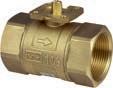
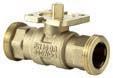
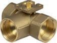
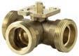
Application
Single-room control
Preheater for ventilation & air-conditioning
Preheater, cooler for ventilation & air-conditioning
Reheater for ventilation & air-conditioning
Chilled ceiling
Static heating
Multi-boiler system
Local heating
2-way
3-way
Combination options with actuator
AKM 105(S)
AKM 115(S)
AKM 115SA
AKF 112
AKF 113(S)
AKM 105(S)
AKM 115(S)
AKM 115SA
AKF 112
AKF 113(S)
AKM 105(S)
AKM 115(S)
AKM 115SA
AKF 112
AKF 113(S)
AKM 105(S)
AKM 115(S)
AKM 115SA
AKF 112
AKF 113(S)
Type designation
Application
Single-room control
Preheater for ventilation & air-conditioning
Preheater, cooler for ventilation & air-conditioning
Reheater for ventilation & air-conditioning
Version
2-way
3-way
Female thread
Male thread
Combination options with actuator
AKM 105(S)
AKM 115(S)
AKM 115SA
AKF 112
AKF 113(S)
AKM 105(S)
AKM 115(S)
AKM 115SA
AKF 112
AKF 113(S)
AKM 105(S)
AKM 115(S)
AKM 115SA
AKF 112
AKF 113(S)
AKM 105(S)
AKM 115(S)
AKM 115SA
AKF 112
AKF 113(S)
AKM 105(S)
AKM 115(S)
AKM 115SA
AKF 112
AKF 113(S)
Further information Page 290Page 292Page 295Page 298Page 301
Features
• 2-way regulating ball valve for continuous control of cold and hot water in closed circuits
• In combination with valve actuators AKM 105(S), 115(S), 115SA and AKF 112, 113(S) as a control unit
• Equal-percentage ball valve characteristic; control contour in the ball directly integrated
• Characteristic can be set with SUT rotary actuator (SAUTER Universal Technology) to linear or quadratic
• Spindle with large sliding surface and PTFE glide ring
• Low torque due to collar mounted on O-ring
• Ball valve with female thread as per ISO 7/1 Rp or NPT
• Body made of DZR (dezincification-resistant) cast brass
• Spindle made of DZR brass with PTFE glide ring
• Ball made of DZR brass, chrome-plated and polished surface
• Spindle seal with double O-ring made of EPDM
• Strainer and screw fitting available as accessories
• Water quality as per VDI 2035
Technical data
Parameters
Nominal pressure
Valve characteristic
Control ratio of ball valve
40 bar
Equal-percentage
500:1
Control ratio with actuator > 50:1
Leakage rate
Ambient conditions

Standards, directives
Overview
Watertight as per EN 60534-4 L/1, better than class 4
Angle of rotation 90°
Operating temperature1) −10...130 °C, no condensation
Operating pressure 40 bar (−10...50 °C) 35 bar (130 °C)
Pressure and temperature dataEN 764, EN 1333
Flow parameter EN 60534 (page 3)
1) At operating temperatures <5 °C and >100 °C, the appropriate accessories must be used.
Accessories
Type Description
0510240001Assembly kit for VK**/BK** ball valves as spare part and as accessory for rotary actuators ASF 112, 113 from index B
0510240011 Adaptor required when temperature of the medium < 5 °C 0510420001Adaptor required when temperature of the medium > 100 °C
0560284015Screw fitting in brass, flat-sealing, female thread/male thread for DN 15 0560284020Screw fitting in brass, flat-sealing, female thread/male thread for DN 20 0560284025Screw fitting in brass, flat-sealing, female thread/male thread for DN 25 0560284032Screw fitting in brass, flat-sealing, female thread/male thread for DN 32 0560284040Screw fitting in brass, flat-sealing, female thread/male thread for DN 40 0560284050Screw fitting in brass, flat-sealing, female thread/male thread for DN 50 0560332015Strainer in gun metal (bronze), −10…150 °C, mesh aperture 0.5 mm, DN 15 0560332020Strainer in gun metal, –10…150 °C, mesh aperture 0.8 mm, DN 20 0560332025Strainer in gun metal (bronze), −10…150 °C, mesh aperture 0.8 mm, DN 25 0560332032Strainer in gun metal, –10…150 °C, mesh aperture 0.8 mm, DN 32 0560332040Strainer in gun metal, –10…150 °C, mesh aperture 0.8 mm, DN 40 0560332050Strainer in gun metal, –10…150 °C, mesh aperture 0.8 mm, DN 50
A 1 unit delivered in each case, unless otherwise specified. See last page for dimensions and scope of delivery of accessories.
/ Warranty: The technical data and pressure differences indicated here are applicable only in combination with SAUTER valve actuators. The warranty does not apply if used with valve actuators from other manufacturers.
/ Definitionof∆ps:Maximum admissible pressure drop in the event of a malfunction (pipe break after the ball valve) at which the actuator reliably closes the ball valve using the return spring.
/ Definitionof∆pmax:Maximum admissible pressure drop in control mode at which the actuator reliably opens and closes the ball valve. Pressure differences
Control
VKR015F350-FF
VKR015F340-FF
VKR015F330-FF
VKR015F320-FF
VKR015F310-FF
VKR015F300-FF
VKR020F320-FF
VKR020F310-FF
VKR020F300-FF
VKR025F320-FF
VKR025F310-FF
VKR025F300-FF
VKR032F320-FF
VKR032F310-FF
VKR032F300-FF
VKR040F320-FF
VKR040F310-FF
VKR040F300-FF
VKR050F320-FF
VKR050F310-FF
VKR050F300-FF
Cannot be used to close with the pressure
ActuatorAKM105SF132AKM115SF132AKM115SAF232AKM115SF152
Running time35/60/120 s35/60/120 s35/60/120 s6 s
Closes against the
VKR015F350-FF
VKR015F340-FF
VKR015F330-FF
VKR015F320-FF
VKR015F310-FF
VKR015F300-FF
VKR020F320-FF
VKR020F310-FF
VKR020F300-FF
VKR025F320-FF
VKR025F310-FF
VKR025F300-FF
ActuatorAKM105SF132AKM115SF132AKM115SAF232AKM115SF152
VKR032F320-FF
VKR032F310-FF
VKR032F300-FF
VKR040F320-FF
VKR040F310-FF
VKR040F300-FF
VKR050F320-FF
VKR050F310-FF
VKR050F300-FF
Cannot be used to close with the pressure
ActuatorAKF112F120AKF112F122AKF113F122AKF113SF122
Closes
VKR015F350-FF
VKR015F340-FF
VKR015F330-FF
VKR015F320-FF
VKR015F310-FF
VKR015F300-FF
VKR020F320-FF
VKR020F310-FF
VKR020F300-FF
VKR025F320-FF
VKR025F310-FF
VKR025F300-FF
VKR032F320-FF
VKR032F310-FF
VKR032F300-FF
VKR040F320-FF
VKR040F310-FF
VKR040F300-FF
VKR050F320-FF
VKR050F310-FF
VKR050F300-FF
3.55.43.55.43.55.43.55.4
2.43.52.43.52.43.52.43.5
Cannot be used to close with the pressure
1) At operating temperatures <5 °C and >100 °C, the appropriate accessories must be used. Valves, control valves, dampers, actuators | Ball valves and ball valve actuators

Features
• 2-way regulating ball valve for continuous control of cold and hot water in closed circuits
• In combination with valve actuators AKM 105(S), 115(S), 115SA and AKF 112, 113(S) as a control unit
• Equal-percentage ball valve characteristic; control contour in the ball directly integrated
• Characteristic can be set with SUT rotary actuator (SAUTER Universal Technology) to linear or quadratic
• Spindle with large sliding surface and PTFE glide ring
• Low torque due to collar mounted on O-ring
• Ball valve with male thread as per ISO 228-1 (G x" B)
• Body made of DZR (dezincification-resistant) cast brass
• Spindle made of DZR brass with PTFE glide ring
• Ball made of DZR brass, chrome-plated and polished surface
• Spindle seal with double O-ring made of EPDM
• Strainer and screw fitting available as accessories
• Water quality as per VDI 2035
Technical data
Parameters
Nominal pressure
Valve characteristic
Control ratio of ball valve
40 bar
Equal-percentage
500:1
Control ratio with actuator > 50:1
Leakage rate
Ambient conditions
Waterproof as per EN 60534-4 L/1, better than class 5
Angle of rotation 90°
Operating temperature1) −10...130 °C, no condensation
Operating pressure
Standards, directives
Liquids: 40 bar (–10...50 °C), 35 bar
Gases: 20 bar
Pressure and temperature dataEN 764, EN 1333
Flow parameter EN 60534 (page 3) Overview
Accessories
Type Description
0510240001Assembly kit for VK**/BK** ball valves as spare part and as accessory for rotary actuators ASF 112, 113 from index B
0510240011 Adaptor required when temperature of the medium < 5 °C
0510420001Adaptor required when temperature of the medium > 100 °C
0361951015Screw fitting for male thread with flat seal, G1 - Rp½
0361951020Screw fitting for male thread with flat seal, G1¼ - Rp¾
0361951025Screw fitting for male thread with flat seal, G1½ - Rp1
0361951032Screw fitting for male thread with flat seal DN 32 0361951040Screw fitting for male thread with flat seal DN 40 0361951050Screw fitting for male thread with flat seal DN 50
0560332015Strainer in gun metal (bronze), −10…150 °C, mesh aperture 0.5 mm, DN 15
0560332020Strainer in gun metal, –10…150 °C, mesh aperture 0.8 mm, DN 20 0560332025Strainer in gun metal (bronze), −10…150 °C, mesh aperture 0.8 mm, DN 25 0560332032Strainer in gun metal, –10…150 °C, mesh aperture 0.8 mm, DN 32 0560332040Strainer in gun metal, –10…150 °C, mesh aperture 0.8 mm, DN 40 0560332050Strainer in gun metal, –10…150 °C, mesh aperture 0.8 mm, DN 50
Combination of VKRA with electric actuators
/ Warranty: The technical data and pressure differences indicated here are applicable only in combination with SAUTER valve actuators. The warranty does not apply if used with valve actuators from other manufacturers.
/ Definitionof∆ps:Maximum admissible pressure drop in the event of a malfunction (pipe break after the ball valve) at which the actuator reliably closes the ball valve using the return spring.
/ Definitionof∆pmax:Maximum admissible pressure drop in control mode at which the actuator reliably opens and closes the ball valve.
Pressure differences ActuatorAKM105F100
Control
Closes against the
ActuatorAKM105F100 AKM105F120
Page
VKRA032F320
VKRA032F310
VKRA032F300
VKRA040F320
VKRA040F310
VKRA040F300
VKRA050F320
VKRA050F310
VKRA050F300
Cannot be used to close with the pressure
ActuatorAKM105SF132AKM115SF132AKM115SAF232AKM115SF152
Page
Control signal2-/3-point, 0...10 V2-/3-point, 0...10 V0…10 V, BACnet MS/TP 2-/3-point, 0...10 V, 4...20 mA
Running time35/60/120 s35/60/120 s35/60/120 s6 s
VKRA015F350
VKRA015F340
VKRA015F330
VKRA015F320
VKRA015F310
VKRA020F320
VKRA020F310
VKRA020F300
VKRA025F320
VKRA025F310
VKRA025F300
VKRA032F320
VKRA032F310
VKRA032F300
VKRA040F320
VKRA040F310
VKRA040F300
VKRA050F320
VKRA050F310
VKRA050F300
Cannot be used to close with the pressure ActuatorAKF112F120AKF112F122AKF113F122AKF113SF122
Closes
VKRA015F350
VKRA015F340
VKRA015F330
VKRA015F320
VKRA015F310
VKRA020F320
VKRA020F310
VKRA020F300
VKRA025F320
VKRA025F310
VKRA025F300
Features
• 3-way regulating ball valve for continuous control of cold and hot water in closed circuits
• In combination with valve actuators AKM 105(S), 115(S), 115SA and AKF 112, 113(S) as a control unit
• Control contour in the ball directly integrated
• Control passage characteristic can be set to linear or quadratic with SUT rotary actuator
• Low torque due to collar mounted on O-ring
• Spindle with large sliding surface and PTFE ring
• Ball valve with female thread as per ISO 7/1 Rp or NPT
• Body made of DZR (dezincification-resistant) cast brass
• Spindle made of DZR brass with PTFE glide ring
• Ball made of DZR brass, chrome-plated and polished surface
• Spindle seal with double O-ring made of EPDM
• Strainer and screw fitting available as accessories
• Water quality as per VDI 2035
Technical data
Parameters
Ambient conditions
Nominal pressure 40 bar
Kvs value, mixing passage −10...−30% through the control passage
Control passage valve characteristicEqual-percentage
Mixing passage valve characteristicLinear
Control ratio of ball valve 500:1
Control ratio with actuator Approx. 50:1
Control passage leakage rateWatertight as per EN 60534-4 L/1, better than class 4
Mixing passage leakage rate< 1%
Angle of rotation 90°
Operating temperature1) −10...130 °C, no condensation
Operating pressure 40 bar (−10...50 °C)
Overview
BKR032F310-FFDN 32

At operating temperatures <5 °C and >100 °C, the appropriate accessories must be used.
Accessories
Type Description
0510240001Assembly kit for VK**/BK** ball valves as spare part and as accessory for rotary actuators ASF 112, 113 from index B
0510240011 Adaptor required when temperature of the medium < 5 °C
0510420001Adaptor required when temperature of the medium > 100 °C
0560284015Screw fitting in brass, flat-sealing, female thread/male thread for DN 15
0560284020Screw fitting in brass, flat-sealing, female thread/male thread for DN 20 0560284025Screw fitting in brass, flat-sealing, female thread/male thread for DN 25 0560284032Screw fitting in brass, flat-sealing, female thread/male thread for DN 32 0560284040Screw fitting in brass, flat-sealing, female thread/male thread for DN 40 0560284050Screw fitting in brass, flat-sealing, female thread/male thread for DN 50 0560332015Strainer in gun metal (bronze), −10…150 °C, mesh aperture 0.5 mm, DN 15 0560332020Strainer in gun metal, –10…150 °C, mesh aperture 0.8 mm, DN 20 0560332025Strainer in gun metal (bronze), −10…150 °C, mesh aperture 0.8 mm, DN 25 0560332032Strainer in gun metal, –10…150 °C, mesh aperture 0.8 mm, DN 32 0560332040Strainer in gun metal, –10…150 °C, mesh aperture 0.8 mm, DN 40
0560332050Strainer in gun metal, –10…150 °C, mesh aperture 0.8 mm, DN 50
A 1 unit delivered in each case, unless otherwise specified. See last page for dimensions and scope of delivery of accessories.
Combination of BKR with electric actuators
/ Warranty: The technical data and pressure differences indicated here are applicable only in combination with SAUTER valve actuators. The warranty does not apply if used with valve actuators from other manufacturers. / Definitionof∆pmax:Maximum admissible pressure drop in control mode at which the actuator reliably opens and closes the ball valve.
Pressure differences
ActuatorAKM105F100
BKR015F340-FF
BKR015F330-FF
BKR015F320-FF
BKR015F310-FF
BKR020F320-FF
BKR020F310-FF
BKR025F310-FF
BKR032F310-FF
BKR040F310-FF
BKR050F310-FF
Cannot be used as distribution valve
ActuatorAKM105SF132AKM115SF132AKM115SAF232AKM115SF152
Control signal2-/3-point, 0...10 V2-/3-point, 0...10 V0…10 V, BACnet
Running time35/60/120 s35/60/120 s35/60/120 s6
BKR015F340-FF
BKR015F330-FF
BKR015F320-FF
BKR015F310-FF
BKR020F320-FF
BKR020F310-FF
BKR025F310-FF
BKR032F310-FF
Cannot be used as distribution valve
ActuatorAKF112F120AKF112F122AKF113F122AKF113SF122
BKR015F340-FF
BKR015F330-FF
BKR015F320-FF
BKR015F310-FF
BKR020F320-FF
BKR020F310-FF
BKR025F310-FF
BKR032F310-FF
BKR040F310-FF
BKR050F310-FF
Cannot be used as distribution valve
Features
• 3-way regulating ball valve for continuous control of cold and hot water in closed circuits
• As a control unit in combination with valve actuators AKM105(S), 115(S), 115SA and AKF112, 113(S)
• Control contour in the ball directly integrated
• Control passage characteristic can be set to linear or quadratic with SUT rotary actuator
• Low torque due to collar mounted on O-ring
• Spindle with large sliding surface and PTFE ring
• Ball valve with male thread as per ISO 228-1 (G x" B)
• Body made of DZR (dezincification-resistant) cast brass
• Spindle made of DZR brass with PTFE glide ring
• Ball made of DZR brass, chrome-plated and polished surface
• Spindle seal with double O-ring made of EPDM
• Strainer and screw fitting available as accessories
• Water quality as per VDI 2035
Technical data
Parameters
Ambient conditions
Nominal pressure
40 bar
Kvs value, mixing passage –10...–30% through the control passage
Valve characteristic, control passageEqual-percentage
Mixing passage valve characteristicLinear
Control ratio of ball valve
500:1
Control ratio with actuator Approx. 50:1
Control passage leakage rateWatertight as per EN 60534-4 L/1, better than class 4
Mixing passage leakage rate< 1% of the Kvs value
Angle of rotation 90°
Operating temperature1) −10...130 °C, no condensation
Operating pressure
40 bar (–10...50 °C)
35 bar (130 °C)
Gases: 20 bar Overview
1) At operating temperatures <5 °C and >100 °C, the appropriate accessories must be used. Valves, control valves, dampers, actuators | Ball valves and ball valve actuators

Accessories
Type Description
0510240001Assembly kit for VK**/BK** ball valves as spare part and as accessory for rotary actuators ASF 112, 113 from index B
0510240011 Adaptor required when temperature of the medium < 5 °C
0510420001Adaptor required when temperature of the medium > 100 °C
0361951015Screw fitting for male thread with flat seal, G1 - Rp½
0361951020Screw fitting for male thread with flat seal, G1¼ - Rp¾
0361951025Screw fitting for male thread with flat seal, G1½ - Rp1
0361951032Screw fitting for male thread with flat seal DN 32
0361951040Screw fitting for male thread with flat seal DN 40
0361951050Screw fitting for male thread with flat seal DN 50
0560332015Strainer in gun metal (bronze), −10…150 °C, mesh aperture 0.5 mm, DN 15
0560332020Strainer in gun metal, –10…150 °C, mesh aperture 0.8 mm, DN 20
0560332025Strainer in gun metal (bronze), −10…150 °C, mesh aperture 0.8 mm, DN 25
0560332032Strainer in gun metal, –10…150 °C, mesh aperture 0.8 mm, DN 32
0560332040Strainer in gun metal, –10…150 °C, mesh aperture 0.8 mm, DN 40
0560332050Strainer in gun metal, –10…150 °C, mesh aperture 0.8 mm, DN 50
Combination of BKRA with electric actuators
/ Warranty: The technical data and pressure differences indicated here are applicable only in combination with SAUTER valve actuators. The warranty does not apply if used with valve actuators from other manufacturers.
/ Definitionof∆pmax:Maximum admissible pressure drop in control mode at which the actuator reliably opens and closes the valve.
Pressure differences
ActuatorAKM105F100 AKM105F120
BKRA015F340
BKRA015F330
BKRA015F320
BKRA015F310
BKRA020F320
BKRA020F310
BKRA025F310
BKRA032F310
BKRA040F310
BKRA050F310
Cannot be used as distribution valve
ActuatorAKM105SF132AKM115SF132AKM115SAF232AKM115SF152 Page
Control signal2-/3-point,
Running time35/60/120 s35/60/120 s35/60/120 s6
BKRA015F340
BKRA015F330
BKRA015F320
BKRA015F310
BKRA020F320
BKRA020F310 BKRA025F310
Cannot be used as distribution valve
ActuatorAKF112F120AKF112F122AKF113F122AKF113SF122
BKRA015F340
BKRA015F330
BKRA015F320
BKRA015F310
BKRA020F320
BKRA020F310
BKRA025F310
BKRA050F3101.03.52.03.52.03.52.03.5
Cannot be used as distribution valve Valves, control valves, dampers, actuators | Ball
Features
• 2-way cut-off ball valve for use in closed circuits in heating, ventilation and air conditioning systems
• As a cut-off device and control unit for 2-point control in combination with valve actuators AKM 105(S), 115(S), 115SA and AKF 112, 113(S)
• Fast cut-off in six seconds with the AKM115SF152 valve actuator
• Low torque due to collar mounted on O-ring
• Ball valve with female thread as per ISO 7/1 Rp
• Body made of dezincification-resistant cast brass
• Ball made of dezincification-resistant brass, chrome-plated and polished surface
• Strainer and screw fitting available as accessories
• Water quality as per VDI 2035
Technical data
Parameters
Ambient conditions
Overview of types
Accessories
Type
Description
Nominal pressure 40 bar
Leakage rate 0.0001 x Kvs value
Angle of rotation 90°
Operating temperature1) −10...130 °C, no condensation
Operating pressure 40 bar (−10...50 °C)
35 bar (130 °C)
0510240001Assembly kit for VK**/BK** ball valves as spare part and as accessory for rotary actuators ASF 112, 113 from index B
0510240011 Adaptor required when temperature of the medium < 5 °C
0510420001Adaptor required when temperature of the medium > 100 °C
0560284015Screw fitting in brass, flat-sealing, female thread/male thread for DN 15
0560284020Screw fitting in brass, flat-sealing, female thread/male thread for DN 20
0560284025Screw fitting in brass, flat-sealing, female thread/male thread for DN 25
0560284032Screw fitting in brass, flat-sealing, female thread/male thread for DN 32
0560284040Screw fitting in brass, flat-sealing, female thread/male thread for DN 40
0560284050Screw fitting in brass, flat-sealing, female thread/male thread for DN 50
1) At operating temperatures <5 °C and >100 °C, the appropriate accessories must be used. Valves, control valves, dampers, actuators | Ball valves and ball valve actuators

0560332015Strainer in gun metal (bronze), −10…150 °C, mesh aperture 0.5 mm, DN 15
0560332020Strainer in gun metal, –10…150 °C, mesh aperture 0.8 mm, DN 20
0560332025Strainer in gun metal (bronze), −10…150 °C, mesh aperture 0.8 mm, DN 25
0560332032Strainer in gun metal, –10…150 °C, mesh aperture 0.8 mm, DN 32
Type Description
0560332040Strainer in gun metal, –10…150 °C, mesh aperture 0.8 mm, DN 40
0560332050Strainer in gun metal, –10…150 °C, mesh aperture 0.8 mm, DN 50
Combination of VKAI with electric actuators
/ Warranty: The technical data and pressure differences indicated here are applicable only in combination with SAUTER valve actuators. The warranty does not apply if used with valve actuators from other manufacturers. / Definitionof∆pmax: Maximum admissible pressure drop in control mode at which the actuator reliably opens and closes the ball valve.
Pressure differences
ActuatorAKM105F100
Page
Control
Control signal2-/3-point, 0...10 V2-/3-point, 0...10 V0…10 V,
Running time35/60/120 s35/60/120 s35/60/120 s6 s
ActuatorAKF112F120AKF112F122AKF113F122AKF113SF122
Valves, control valves, dampers, actuators | Ball valves and ball valve actuators
Features
• 2-way cut-off ball valve for use in closed circuits in heating, ventilation and air conditioning systems
• As a cut-off device and control unit for 2-point control in combination with valve actuators AKM 105(S), 115(S), 115SA and AKF 112, 113(S)
• Fast changeover in six seconds with the AKM115SF152 valve actuator
• Low torque due to collar mounted on O-ring
• Ball valve with male thread as per ISO 228-1 (G x" B)
• Body made of dezincification-resistant cast brass
• Ball made of dezincification-resistant brass, chrome-plated and polished surface
• Strainer and screw fitting available as accessories
• Water quality as per VDI 2035
Technical data
Parameters
Ambient conditions
Nominal pressure 40 bar Leakage rate
Waterproof as per EN 60534-4 L/1, better than class 5
Angle of rotation 90°
Operating temperature
Operating pressure
Overview of types
−10...130 °C, no condensation
Liquids: 40 bar (–10...50 °C)
35 bar (130 °C)
Gases: 20 bar
Accessories
Type Description
0510240001Assembly kit for VK**/BK** ball valves as spare part and as accessory for rotary actuators ASF 112, 113 from index B
0510240011 Adaptor required when temperature of the medium < 5 °C 0510420001Adaptor required when temperature of the medium > 100 °C
0361951015Screw fitting for male thread with flat seal, G1 - Rp½
0361951020Screw fitting for male thread with flat seal, G1¼ - Rp¾
0361951025Screw fitting for male thread with flat seal, G1½ - Rp1
0361951032Screw fitting for male thread with flat seal DN 32
0361951040Screw fitting for male thread with flat seal DN 40
0361951050Screw fitting for male thread with flat seal DN 50
0560332015Strainer in gun metal (bronze), −10…150 °C, mesh aperture 0.5 mm, DN 15
0560332020Strainer in gun metal, –10…150 °C, mesh aperture 0.8 mm, DN 20
0560332025Strainer in gun metal (bronze), −10…150 °C, mesh aperture 0.8 mm, DN 25
0560332032Strainer in gun metal, –10…150 °C, mesh aperture 0.8 mm, DN 32

Type Description
0560332040Strainer in gun metal, –10…150 °C, mesh aperture 0.8 mm, DN 40
0560332050Strainer in gun metal, –10…150 °C, mesh aperture 0.8 mm, DN 50
Combination of VKAA with electric actuators
/ Warranty: The technical data and pressure differences indicated here are applicable only in combination with SAUTER valve actuators. The warranty does not apply if used with valve actuators from other manufacturers.
/ Definitionof∆pmax: Maximum admissible pressure drop in control mode at which the actuator reliably opens and closes the ball valve.
/ Definitionof∆ps: Maximum admissible pressure drop in the event of a malfunction (pipe break after the valve) at which the actuator reliably closes the valve by means of a return spring.
Pressure differences
ActuatorAKM105F100
ActuatorAKM105SF132AKM115SF132AKM115SAF232AKM115SF152
Control signal2-/3-point, 0...10 V2-/3-point, 0...10 V0…10 V, BACnet MS/TP 2-/3-point, 0...10 V, 4...20 mA
Running time35/60/120 s35/60/120 s35/60/120 s6 s
Operating voltage24 VAC/DC 24 VAC/DC
ActuatorAKF112F120AKF112F122AKF113F122AKF113SF122
Page
BKLI: 3-way changeover ball valve (L) with female thread, PN 40
Features
• 3-way changeover ball valve with L-bore for use in closed circuits in heating, ventilation and air conditioning systems
• For changing over volume flows in combination with valve actuators AKM 105(S), 115(S), 115SA and AKF 112, 113(S).
• Fast changeover in six seconds with the AKM115SF152 valve actuator
• Low torque due to collar mounted on O-ring
• Spindle with friction ring and double O-ring seal
• Ball valve with female thread as per ISO 7/1 Rp
• Body made of dezincification-resistant cast brass
• Ball made of dezincification-resistant brass, chrome-plated and polished surface
• Strainer and screw fitting available as accessories
• Water quality as per VDI 2035
Technical data
Parameters
Ambient conditions
Nominal pressure
40 bar
Leakage rate, through passage0.0001 x Kvs value
Leakage rate, bypass
0.0001 x Kvs value
Angle of rotation 90°
Operating temperature1) −10...130 °C, no condensation
Operating pressure 40 bar (−10...50 °C) 35 bar (130 °C)
Overview of types Type
Accessories
Type Description
0510240001Assembly kit for VK**/BK** ball valves as spare part and as accessory for rotary actuators ASF 112, 113 from index B 0510240011 Adaptor required when temperature of the medium < 5 °C 0510420001Adaptor required when temperature of the medium > 100 °C 0560284015Screw fitting in brass, flat-sealing, female thread/male thread for DN 15 0560284020Screw fitting in brass, flat-sealing, female thread/male thread for DN 20 0560284025Screw fitting in brass, flat-sealing, female thread/male thread for DN 25 0560284032Screw fitting in brass, flat-sealing, female thread/male thread for DN 32 0560284040Screw fitting in brass, flat-sealing, female thread/male thread for DN 40 0560284050Screw fitting in brass, flat-sealing, female thread/male thread for DN 50
1) At operating temperatures <5 °C and >100 °C, the appropriate accessories must be used. Valves, control valves, dampers, actuators | Ball

Type
Description
0560332015Strainer in gun metal (bronze), −10…150 °C, mesh aperture 0.5 mm, DN 15
0560332020Strainer in gun metal, –10…150 °C, mesh aperture 0.8 mm, DN 20
0560332025Strainer in gun metal (bronze), −10…150 °C, mesh aperture 0.8 mm, DN 25
0560332032Strainer in gun metal, –10…150 °C, mesh aperture 0.8 mm, DN 32
0560332040Strainer in gun metal, –10…150 °C, mesh aperture 0.8 mm, DN 40
0560332050Strainer in gun metal, –10…150 °C, mesh aperture 0.8 mm, DN 50
Combination of BKLI with electric actuators
/ Warranty: The technical data and pressure differences indicated here are applicable only in combination with SAUTER valve actuators. The warranty does not apply if used with valve actuators from other manufacturers. / Definitionof∆pmax: Maximum admissible pressure drop in control mode at which the actuator reliably opens and closes the ball valve.
Pressure differences
ActuatorAKM105F100 AKM105F120
Page
Control signal2-/3-point 2-/3-point 2-/3-point 2-/3-point
BKLI015F300
Control signal2-/3-point, 0...10 V2-/3-point, 0...10 V0…10 V, BACnet MS/TP 2-/3-point, 0...10 V, 4...20 mA
Running time35/60/120 s35/60/120 s35/60/120 s6 s
BKLI015F300 BKLI020F300 BKLI025F300
BKLI032F300 BKLI040F300
BKLI050F300
BKLI015F300
BKLI020F300
BKLI025F300
BKLI032F300
BKLI040F300
BKLI050F300
2.05.42.05.42.05.42.05.4
Valves, control valves, dampers, actuators | Ball valves and ball valve actuators
BKTI: 3-way changeover ball valve (T) with female thread, PN 40
Features
• 3-way changeover ball valve with T-bore for use in closed circuits in heating, ventilation and air conditioning systems
• For changing over volume flows in combination with valve actuators AKM 105(S), 115(S), 115SA and AKF 112, 113(S)
• Fast changeover in six seconds with the AKM115SF152 valve actuator
• Low torque due to collar mounted on O-ring
• Spindle with friction ring and double O-ring seal
• Ball valve with female thread as per ISO 7/1 Rp
• Body made of dezincification-resistant cast brass
• Ball made of dezincification-resistant brass, chrome-plated and polished surface
• Strainer and screw fitting available as accessories
• Water quality as per VDI 2035
Technical data
Parameters
Ambient conditions
Nominal pressure 40 bar
Leakage rate, through passage0.0001 x Kvs value
Leakage rate, bypass < 0.01 x Kvs value
Angle of rotation 90°
Operating temperature1) −10...130 °C, no condensation
Operating pressure 40 bar (−10...50 °C) 35 bar (130 °C)
Overview of types Type

Accessories
Type Description
0510240001Assembly kit for VK**/BK** ball valves as spare part and as accessory for rotary actuators ASF 112, 113 from index B
0510240011 Adaptor required when temperature of the medium < 5 °C
0510420001Adaptor required when temperature of the medium > 100 °C
0560284015Screw fitting in brass, flat-sealing, female thread/male thread for DN 15
0560284020Screw fitting in brass, flat-sealing, female thread/male thread for DN 20
0560284025Screw fitting in brass, flat-sealing, female thread/male thread for DN 25
0560284032Screw fitting in brass, flat-sealing, female thread/male thread for DN 32
0560284040Screw fitting in brass, flat-sealing, female thread/male thread for DN 40 0560284050Screw fitting in brass, flat-sealing, female thread/male thread for DN 50
1) At operating temperatures <5 °C and >100 °C, the appropriate accessories must be used.
Type Description
0560332015Strainer in gun metal (bronze), −10…150 °C, mesh aperture 0.5 mm, DN 15
0560332020Strainer in gun metal, –10…150 °C, mesh aperture 0.8 mm, DN 20
0560332025Strainer in gun metal (bronze), −10…150 °C, mesh aperture 0.8 mm, DN 25
0560332032Strainer in gun metal, –10…150 °C, mesh aperture 0.8 mm, DN 32
0560332040Strainer in gun metal, –10…150 °C, mesh aperture 0.8 mm, DN 40
0560332050Strainer in gun metal, –10…150 °C, mesh aperture 0.8 mm, DN 50
Combination of BKTI with electric actuators
/ Warranty: The technical data and pressure differences indicated here are applicable only in combination with SAUTER valve actuators. The warranty does not apply if used with valve actuators from other manufacturers. / Definitionof∆pmax: Maximum admissible pressure drop in control mode at which the actuator reliably opens and closes the ball valve.
Pressure differences
ActuatorAKM105F100
Page
Control signal2-/3-point 2-/3-point 2-/3-point 2-/3-point
BKTI015F300
ActuatorAKM105SF132AKM115SF132AKM115SAF232AKM115SF152
Control signal2-/3-point, 0...10 V2-/3-point, 0...10 V0…10 V, BACnet MS/TP 2-/3-point, 0...10 V, 4...20 mA
Running time35/60/120 s35/60/120 s35/60/120 s6 s Operating
BKTI032F300
BKTI015F300
BKTI020F300
BKTI025F300
BKTI032F300
BKTI040F300
BKTI050F300
Valves, control valves, dampers, actuators | Ball valves and ball valve actuators
Features
• 3-way changeover ball valve with T-bore for use in closed circuits in heating, ventilation and air conditioning systems
• For changing over volume flows in combination with valve actuators AKM 105(S), 115(S), 115SA and AKF 112, 113(S)
• Fast changeover in six seconds with the AKM115SF152 valve actuator
• Low torque due to collar mounted on O-ring
• Spindle with friction ring and double O-ring seal
• Ball valve with male thread as per ISO 228-1 (G x" B)
• Body made of dezincification-resistant cast brass
• Ball made of dezincification-resistant brass, chrome-plated and polished surface
• Strainer and screw fitting available as accessories
• Water quality as per VDI 2035
Technical data
Parameters
Ambient conditions
Nominal pressure
40 bar
Leakage rate, through passageWaterproof as per EN 60534-4 L/1, better than class 4
Leakage rate, bypass < 1% of the Kvs value
Angle of rotation
Operating temperature
Operating pressure
90°
−10...130 °C, no condensation
40 bar (–10...50 °C)
35 bar (130 °C)
Gases: 20 bar Overview
Accessories
Type Description
0510240001Assembly kit for VK**/BK** ball valves as spare part and as accessory for rotary actuators ASF 112, 113 from index B
0510240011 Adaptor required when temperature of the medium < 5 °C 0510420001Adaptor required when temperature of the medium > 100 °C
0361951015Screw fitting for male thread with flat seal, G1 - Rp½ 0361951020Screw fitting for male thread with flat seal, G1¼ - Rp¾ 0361951025Screw fitting for male thread with flat seal, G1½ - Rp1
0361951032Screw fitting for male thread with flat seal DN 32 0361951040Screw fitting for male thread with flat seal DN 40 0361951050Screw fitting for male thread with flat seal DN 50 0560332015Strainer in gun metal (bronze), −10…150 °C, mesh aperture 0.5 mm, DN 15

Type Description
0560332020Strainer in gun metal, –10…150 °C, mesh aperture 0.8 mm, DN 20
0560332025Strainer in gun metal (bronze), −10…150 °C, mesh aperture 0.8 mm, DN 25
0560332032Strainer in gun metal, –10…150 °C, mesh aperture 0.8 mm, DN 32
0560332040Strainer in gun metal, –10…150 °C, mesh aperture 0.8 mm, DN 40
0560332050Strainer in gun metal, –10…150 °C, mesh aperture 0.8 mm, DN 50
Combination of BKTA with electric actuators
/ Warranty: The technical data and pressure differences indicated here are applicable only in combination with SAUTER valve actuators. The warranty does not apply if used with valve actuators from other manufacturers.
/ Definitionof∆pmax: Maximum admissible pressure drop in control mode at which the actuator reliably opens and closes the ball valve.
/ Definitionof∆ps: Maximum admissible pressure drop in the event of a malfunction (pipe break after the valve) at which the actuator reliably closes the valve by means of a return spring.
Pressure differences
ActuatorAKM105F100
Control signal2-/3-point 2-/3-point
BKTA015F300
Control
Running time35/60/120 s35/60/120 s35/60/120 s6 s
Operating voltage24 VAC/DC 24
BKTA050F300
BKTA015F300
BKTA020F300
BKTA025F300
BKTA032F300
BKTA040F300
BKTA050F300
2.05.42.05.42.05.42.05.4
The 6-way ball valve from SAUTER is a compact and precise alternative for regulating heated/chilled ceilings and fan coils in four-pipe systems. It doubles as a regulating and changeover ball valve. While conventional solutions operate with up to four 2-way valves, four actuators and two controllers, now only one 6-way ball valve and an actuator are required. Their compact construction enables the devices to be installed in false ceilings without difficulty.
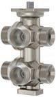
Type designation
Application
Single-room control
Preheater for ventilation & air-conditioning
Preheater, cooler for ventilation & air-conditioning
Reheater for ventilation & air-conditioning
Chilled ceiling
Static heating
Multi-boiler system
Local heating
Version
Nominal pressure
Combination options with actuator
PN 16
AKM 115(S)
AKM 115SA
AKF 112
AKF 113(S)
Further information Page 305
Features
• 6-way ball valve for changeover or continuous control of heating and cooling circuits in a 4-pipe system
• Body made of moulded brass CW602N (dezincification-resistant) or CW617N
• With male thread as per ISO 228
• Kvs selection with exchangeable orifice plates
• In combination with valve actuators AKM 115(S), 115SA and AKF 112, 113(S) as a control unit
• Strainer and screw fitting available as accessories
• Water quality as per VDI 2035
Technical data
Parameters
Nominal pressure
Valve characteristic
Leakage rate
Ambient conditions
Standards, directives
PN 16
Quasi-linear
Class A as per EN 12266-1
Total angle of rotation 90° (valve closed at 45°)
Operating temperature 5…90 °C
Pressure and temperature dataEN 764, EN 1333
Flow parameter EN 60534
PED 2014/68/EU
Fluid group II, liquid No CE label as per article 4.3
B2KL020F411DN 20G ¾" B2.8 m³/hMoulded
A Kvs value without orifice plate. Kvs values can be adapted using orifice plates.
Orifice plates for setting the Kvs value
Orifice plate set for B2KL DN15 Part number
Kvs value
0.25 m3/h
0.4 m3/h
0.63 m3/h 1 m3/h
0589540001
Supplied with the 6-way ball valve
Orifice plate set for B2KL DN20 Part number Kvs value
0.7 m3/h
1 m3/h
1.6 m3/h
2.1 m3/h
0589540002
Supplied with the 6-way ball valve

Accessories
Type Description
0378133015Threaded sleeve, R½, flat-sealing, with cap nut and flat seal, G¾ - R½
0378134015Solder nipple, Ø 15, flat-sealing, with cap nut and flat seal, G¾
0580240002Insulation shell for 6-way ball valve DN 15
0580240003Insulation shell for 6-way ball valve DN 20
0560284015Screw fitting in brass, flat-sealing, female thread/male thread for DN 15
0560284020Screw fitting in brass, flat-sealing, female thread/male thread for DN 20
0580090001Pliers for changing orifice plate on 6-way ball valve DN 15 and DN 20
0580240001Fitting bracket for 6-way ball valve DN 15 and DN 20
0560332015Strainer in gun metal (bronze), −10…150 °C, mesh aperture 0.5 mm, DN 15
0560332020Strainer in gun metal, –10…150 °C, mesh aperture 0.8 mm, DN 20
0560332025Strainer in gun metal (bronze), −10…150 °C, mesh aperture 0.8 mm, DN 25
of
/ Warranty: The technical data and pressure differences indicated here are applicable only in combination with SAUTER valve actuators. The warranty does not apply if used with valve actuators from other manufacturers.
/ Definitionof∆ps:Maximum admissible pressure drop in the event of a malfunction (pipe break after the ball valve) at which the actuator reliably closes the ball valve using the return spring.
/ Definitionof∆pmax:Maximum admissible pressure drop in control mode at which the actuator reliably opens and closes the valve.
Pressure differences
ActuatorAKM115F120AKM115F122AKM115SF132AKM115SAF232
Page
Control signal2-/3-point 2-/3-point 2-/3-point, 0...10 V0…10 V, BACnet MS/TP
Running time120 s 120 s 35/60/120 s35/60/120 s
Operating voltage230 VAC 24 VAC 24 VAC/DC 24 VAC/DC
ActuatorAKF112F120AKF112F122AKF113F122AKF113SF122
B2KL015F400
B2KL015F401
B2KL020F411 2.02.02.02.02.02.02.02.0
SAUTER actuators for ball valves adapt themselves automatically to the ball valves and enable them to be controlled accurately. The actuators are switched off as a function of the torque. These SAUTER actuators are suitable for operating two- and three-way ball valves. Furthermore, they can be used for controllers with switching or continuous outputs.
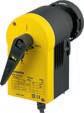
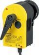
Technical data
Adjustable characteristic Equal-percentageEqual-percentage, linear, quadratic

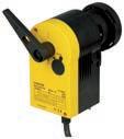
linear, quadratic
linear, quadratic
2-point
Spring return
Combination options with ball valve
Further
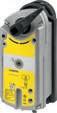
Type designation
Technical data
Adjustable characteristic
2-point
3-point
BACnet MS/TP
Positioner
High-speed
Spring return
Combination options with ball valve
Further information Page 315 Page 316
Features
• For operating 2- and 3-way ball valves VKR, VKRA, BKR, BKRA, VKAI, VKAA, BKLI, BKTI, BKTA and 6-way ball valve B2KL
• For controllers with a switching output (2-/3-point control)
• Assembly with ball valves without the use of tools
• Synchronous motor with electronic activation and cut-out
• Maintenance-free gear unit
• Gear unit can be disengaged in order to position the ball valve manually (using the lever)
• Bracket and bayonet ring made of glass-fibre-reinforced plastic for fitting onto ball valve
• Fitting vertically upright to horizontal, not suspended
Technical data
Power supply
Parameters
Ambient conditions
Function
Construction
Power supply 230 VAC ±15%, 50...60 Hz
Power supply 24 VAC ±20%, 50...60 Hz
Power cable 1.2 m, 3 × 0.75 mm2
Response time Min. 200 ms
Angle of rotation 90°
Ambient temperature –10...55 °C
Ambient humidity 5...95% rh, no condensation
Media temperature1) Max. 100 °C
Control 2-/3-point
Weight
Housing
Standards and directives
0.7 kg
Lower section black, upper section yellow
Housing material Fire-retardant plastic
Type of protection2)
IP54 (EN 60529), horizontal Protection class 24 V III (EN 60730)
Protection class 230 V II (EN 60730)
Over-voltage categories III
Degree of contamination II
CE conformity according toDirective 2006/95/EC EN 60730-1/EN 60730-2-14 EMC Directive 2014/30/EUEN 61000-6-1, EN 61000-6-2 EN 61000-6-3, EN 61000-6-4
Overview of types
1) At media temperatures < 5 °C or > 100 °C, appropriate accessory must be used
2) See fitting instructions P100001578

Valves, control valves, dampers, actuators | Ball valves and ball valve actuators
Accessories
Type Description
0510420001Adaptor required when temperature of the medium > 100 °C
0510240011Adaptor required when temperature of the medium < 5 °C
0510480001Auxiliary change-over contacts, single
0510480002Auxiliary change-over contacts, double
A Auxiliary change-over contacts: Infinitely variable 0...100%, admissible load 5(2) A, 24...230 V
Features
• For operating 2- and 3-way ball valves VKR, VKRA, BKR, BKRA, VKAI, VKAA, BKLI, BKTI, BKTA and 6-way ball valve B2KL
• For controllers with constant output (0...10 V) or switching output (2-/3-point control)
• Assembly with ball valve without the use of tools
• Stepping motor with SAUTER Universal Technology (SUT) electronic control unit
• Electronic force-dependent motor cut-off
• Automatic recognition of applied control signal (continuous or switched)
• Coding switch for selecting characteristic and running time (35 s, 60 s, 120 s)
• Type of characteristic (linear/quadratic/equal-percentage) can be set on the actuator
• Direction of operation can be selected directly on the cable
• Maintenance-free gear unit
• Gear unit can be disengaged in order to position the ball valve manually (using the lever)
• Bracket and bayonet ring made of glass-fibre-reinforced plastic for fitting onto ball valve
Technical data
Power supply
Parameters
Positioner
Ambient conditions
Construction
Standards, directives
Power supply 24 VAC ±20%, 50...60 Hz
Power supply 24 VDC −10%...20%
Power consumption
4.9 W, 8.7 VA
Running time1) 35/60/120 s
Angle of rotation 90°
Response time 200 ms
Power cable 1.2 m, 5 × 0.5 mm2
Positioning signal y 0...10 V, Ri > 100 kΩ
Positional feedback signal 0...10 V, load > 10 kΩ
Starting point U0 0 V or 10 V
Control span ΔU 10 V
Switching range Xsh 200 mV
Media temperature2) Max. 100 °C
Ambient temperature −10...55 °C
Ambient humidity 5...95% rh, no condensation
Fitting
Vertically upright to horizontal, not suspended
Weight 0.7 kg
Housing
Housing material
Type of protection
Lower section black, upper section yellow
Flame-retardant plastic
IP54 as per EN 60529
Protection class III as per IEC 60730
CE conformity according toEMC Directive 2014/30/EUEN 61000-6-1, EN 61000-6-3 EN 61000-6-4
1) For a running time of 35 s, the torque is halved
2) At media temperatures < 5 °C or > 100 °C, appropriate accessory must be used

Overview of types
Type
Accessories
Type Description
0313529001Split-range unit for setting sequences
0510420001Adaptor required when temperature of the medium > 100 °C
0510240011Adaptor required when temperature of the medium < 5 °C
0510480001Auxiliary change-over contacts, single 0510480002Auxiliary change-over contacts, double
A Auxiliary change-over contacts: Infinitely variable 0...100%, admissible load 5(2) A, 24...230 V
Features
• For operating 2- and 3-way ball valves VKR, VKRA, BKR, BKRA, VKAI, VKAA, BKLI, BKTI, BKTA and 6-way ball valve B2KL
• For controllers with constant output (0...10 V / 4...20 mA) or switching output (2-/3-point control)
• Assembly with ball valve without the use of tools
• Brushless motor with electronic activation and cut-out
• Intelligent adaptation of rotation angle, incl. feedback adjustment
• Electronic force-dependent cut-off
• Direction of rotation selected with DIP switch
• Pulse length correction in 3-point operation, i.e. internal adjustment of start-up time
• Gear unit can be disengaged in order to position the ball valve manually (using the lever)
• Maintenance-free
• Bracket and bayonet ring made of glass-fibre-reinforced plastic for fitting onto ball valve
Technical data
Power supply
Parameters
Positioner
Ambient conditions
Construction
Power supply 24 VAC ±20%, 50…60 Hz
Power supply 24 VDC −10%...20%
Power consumption 6.5 W, 9 VA (at nominal voltage)
Nominal torque 8 Nm
Operating noise (unloaded)< 49 dB(A)
Response time 10 ms
Angle of rotation 90°
Running time 6.0 s
Characteristic linear
Positioning signal y 0…10 V / 2…10 V, Ri = 100 kΩ, 0…20 mA / 4…20 mA, Ri = 500 Ω
Positional feedback signal y0 0...10 V, load > 10 kΩ
Starting point U0 0 or 10 V / 2 or 10 V
Starting point I0 0 or 20 mA / 4 or 20 mA
Control span ΔU 10 V
Switching range Xsh 100 mV
Control span ΔI 20 mA
Switching range Xsh 0.1 mA
Operating temperature −20…55 °C
Media temperature1) Max. 100 °C
Storage and transport temperature−30…65 °C
Ambient humidity 5…85% rh, no condensation
Fitting
Vertically upright to horizontal
Dimensions W × H × D 70 × 138 × 127 mm
Weight 0.7 kg
Housing
Lower section black, upper section yellow
Housing material Fire-retardant plastic
Power cable 1.2 m, 6 × 0.5 mm²
1) At media temperature > 100 °C, appropriate accessory must be used

Standards and directives
0510240011Adaptor required when temperature of the medium < 5 °C Valves, control valves, dampers, actuators | Ball valves and ball valve actuators
Type of protection IP54 (EN 60529), horizontal Protection class III (EN 60730)
CE conformity according toEMC Directive 2014/30/EUEN 61000-6-1, EN 61000-6-2 EN 61000-6-3, EN 61000-6-4
Overview of types Type
Accessories
Type Description
0313529001Split-range unit for setting sequences
0510420001Adaptor required when temperature of the medium > 100 °C
Features
• For operating 2- and 3-way ball valves VKR, VKRA, BKR, BKRA, VKAI, VKAA, BKLI, BKTI, BKTA and 6-way ball valve B2KL
• For controllers with a switching output (2-/3-point control)
• Returns to the starting position in the event of a power failure or the activation of a safety device
• Electronic torque-dependent cut-off
• Direction of rotation can be selected during fitting
Technical data
Power supply
Parameters
Ambient conditions
Construction
Power supply 230 VAC ±10%, 50...60 Hz
Power supply 24 VAC ±20%, 50...60 Hz
Power supply 24...48 V= ±20%
Rotational torque and holding torque7 Nm
Angle of rotation Max. 95°
Power cable 0.9 m, 0.75 mm² (fixed to housing)
Running time for 90° motor90 s
Running time for 90° spring15 s
Ambient
Weight
Standards and directives
1.2 kg
Housing Two-piece
Housing material Cast aluminium
Type of protection
IP54 as per EN 60529
IP42 depending on fitting position
Protection class 230 V II (EN 60730)
Protection class 24 V III (EN 60730)
CE conformity according toEMC Directive 2014/30/EUEN 61000-6-2, EN 61000-6-3
Only for AKF120F120
Low-Voltage Directive 2014/35/EUEN 60730-1, EN 60730-2-14
Over-voltage categories III
Degree of contamination II
Overview of types
Type
Accessories
Type Description
0510240001Assembly kit for VK**/BK** ball valves as spare part and as accessory for rotary actuators ASF 112, 113 from index B

Features
• For operating 2- and 3-way ball valves VKR, VKRA, BKR, BKRA, VKAI, VKAA, BKLI, BKTI, BKTA and 6‑way ball valve B2KL
• For controllers with a continuous output (0…10 V)
• Returns to the starting position in the event of a power failure or the activation of a safety device
• Electronic torque-dependent cut-off
• Direction of rotation can be selected during fitting
Technical data
Power supply
Parameters
Positioner
Ambient conditions
Construction
Power supply 24 VAC ±20%, 50...60 Hz
Power supply 24...48 V= ±20%
Rated power during continuous operation 3.5 W, 5 VA
Power consumption when idle2.5 W, 2.5 VA
Positioning signal y 0...10 V, Ri = 100 kΩ
Positional feedback signal 0...10 V (0...100%)
Admissible load > 10 kΩ
Starting point U0 0 V
Control span ΔU 10 V
Switching range Xsh 0.2 V
Rotational torque and holding torque7 Nm
Angle of rotation Max. 95°
Power cable 0.9 m, 4 × 0.75 mm² (fixed to housing)
Running time for 90° motor90 s
Running time for 90° spring15 s
Ambient temperature –32...55 °C
Ambient humidity < 95% rh
Weight
Standards and directives
1.3 kg
Housing Two-piece
Housing material Cast aluminium
Type of protection IP54 as per EN 60529
Protection class III as per IEC 60730
CE conformity according toEMC Directive 2014/30/EUEN 61000-6-2, EN 61000-6-3
Overview of types
Type Features
AKF113SF122Rotary actuator with spring return and positioner
Accessories
Type Description
0510240001Assembly kit for VK**/BK** ball valves as spare part and as accessory for rotary actuators ASF 112, 113 from index B

SAUTER control valves are used to control heating and cooling systems. The 3 way version is suitable for controlling and change-over functions, while the 4 way version is employed for higher temperatures in the return circuit.
SAUTER butterfly valves are very versatile and are used for control and shut-off functions. Because they close absolutely tightly, they reduce energy consumption.

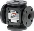
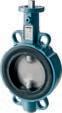
AR30 W, ASM 105, 115, 124 ADM 322(S)
AR30 W, ASM 105, 115, 124 ADM 322(S)
AR30 W, A44 W, ASF 122, 123
124(S)
134(S)
322(S)
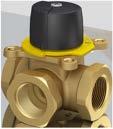
0510240013ADM322 mounting kit with M3R, M4R, MH32, MH42 0361977001Assembly materials for M3R, M4R, MH32F, MH42F with ASM 124 0361977002Assembly materials for M3R, M4R, MH32R/F, MH42R with ASM 105, 115 Valves, control
Features
• M3R: 3-way valves with nominal diameters DN 15...50
• M4R: 4-way valves with nominal diameters DN 20...50
• Used in combination with the ADM 322 and ASM 105, 115, 124 motorised actuators
• Manual adjustment by means of lever and end stops
• Body, cover, front gate and spindle made of brass
Technical data
Parameters

Ambient conditions
Nominal pressure 10 bar Angle of rotation 90°
Valve characteristic Linear Leakage rate < 0.1%
Operating
Overview of types
M3R020F200DN 20 (Rp¾)
M3R025F200DN 25 (Rp1)
M3R032F200DN 32 (Rp1¼)
M3R040F200DN 40 (Rp1½)
M4R020F200DN 20 (Rp¾)
M4R025F200DN 25 (Rp1)
M4R032F200DN 32 (Rp1¼)
M4R040F200DN 40 (Rp1½)
M4R050F200DN 50 (Rp2)
Accessories
Type Description
Combination of M3R/M4R with electric actuators
/ Warranty: The technical data and pressure differences indicated here are applicable only in combination with SAUTER valve actuators. The warranty does not apply if used with valve actuators from other manufacturers.
/ Definitionof∆ps:Maximum admissible pressure drop in the event of a malfunction (pipe break after control valve) at which the actuator reliably closes the valve by means of a return spring.
/ Definitionof∆pmax:Maximum admissible pressure drop in control mode at which the actuator reliably opens and closes the valve.
ActuatorASM105F100ASM105F120ASM105F122ASM105SF132ASM115F120ASM115F122ASM115SF132
Page
Nominal torque5 Nm 5
Control signal2-/3-point2-/3-point2-/3-point2-/3-point, 0...10 V2-/3-point2-/3-point2-/3-point, 0...10 V
Running time30 s 120 s 120 s 35/60/120 s120 s 120 s 60/120 s
Operating voltage230 V~230
M3R025F200
M3R032F200
M3R040F200 M3R050F200
M4R025F200
M4R032F200
M4R040F200
M4R050F200
Cannot be used as distribution valve
ActuatorADM322F120
ADM322F122
ADM322HF120
ADM322HF122
ADM322PF120
ADM322PF122
Control signal3-point 2-/3-point, 0...10 V2-/3-point 2-/3-point, 0...10 V
Running time120 s 30/60/120 s120 s 60/120 s
Operating voltage24 VAC/DC / 230 V24 VAC/DC 24 VAC/DC / 230 V24 VAC/DC / 230 V As control valve
M3R015F200
M3R020F200
M3R025F200
M4R020F200
M4R025F200
M3R032F200
M3R040F200
M3R050F200
M4R032F200
M4R040F200
M4R050F200
Cannot be used as distribution valve
A Accessories required: Assembly materials; see accessories. With ASM 124, it is not possible to fit auxiliary contacts or a potentiometer Valves, control
Valves, control valves, dampers, actuators | Control valves and rotary and damper actuators
Features
• MH32F: 3-way valves with nominal diameters DN 20...150
• MH42F: 4-way valves with nominal diameters DN 32...50
• Can be combined with motorised actuators ADM 322 and ASM 105, 115, 124
• Manual adjustment via lever
• Body made of grey cast iron; brass gate
• Spindle made of brass up to DN 25 and stainless steel from DN 32
• Stuffing box with double O-ring guarantees the tightness of the seal at the spindle
Technical data
Parameters
Ambient conditions
Nominal pressure 6 bar
Angle of rotation 90°
Valve characteristic Linear
Operating temperature 2...110 °C
Operating pressure Max. 6 bar
Overview of types
3-way control valve
4-way control valve

A MH32F20...25: 3-way valve: Zinc cover, brass spindle
A MH32F32...150: 3-way valve: Cover made of grey cast iron, spindle made of stainless steel
A MH42F32...50: 4-way valve: Cover made of grey cast iron, spindle made of stainless steel
Accessories
Type Description
0360392020Welding flange, DN 20, smooth, PN 6, incl. asbestos-free seal
0360392025Welding flange, DN 25, smooth, PN 6, incl. asbestos-free seal
0360392032Welding flange, DN 32, smooth, PN 6, incl. asbestos-free seal
0360392040Welding flange, DN 40, smooth, PN 6, incl. asbestos-free seal
0360392050Welding flange, DN 50, smooth, PN 6, incl. asbestos-free seal
0360392065Welding flange, DN 65, smooth, PN 6, incl. asbestos-free seal
0360392080Welding flange, DN 80, smooth, PN 6, incl. asbestos-free seal
0360392100Welding flange, DN 100, smooth, PN 6, incl. asbestos-free seal 0360392125Welding flange, DN 125, smooth, PN 6, incl. asbestos-free seal
0360392150Welding flange, DN 150, smooth, PN 6, incl. asbestos-free seal
Type Description
0361977001Assembly materials for M3R, M4R, MH32F, MH42F with ASM 124
0361977002Assembly materials for M3R, M4R, MH32R/F, MH42R with ASM 105, 115 0510240013ADM322 mounting kit with M3R, M4R, MH32, MH42
/ Warranty: The technical data and pressure differences indicated here are applicable only in combination with SAUTER valve actuators. The warranty does not apply if used with valve actuators from other manufacturers.
/ Definitionof∆ps:Max. admissible pressure drop in the event of a malfunction (pipe break after control valve) at which the actuator reliably closes the control valve using the return spring.
/ Definitionof∆pmax:Maximum admissible pressure drop in control mode at which the actuator reliably opens and closes the control valve.
Pressure differences
ActuatorASM105F100ASM105F120ASM105F122ASM105SF132ASM115F120ASM115F122ASM115SF132
Page 336 336 336 338 336 336 338
Nominal torque5 Nm 5 Nm 5 Nm 5 Nm 10 Nm 10 Nm 10
Control signal2-/3-point2-/3-point2-/3-point2-/3-point, 0...10 V2-/3-point2-/3-point2-/3-point, 0...10 V
Running time30 s
Cannot be used as distribution valve
ActuatorADM322F120
ADM322F122
ADM322HF120
ADM322HF122
ADM322PF120
ADM322PF122
Torque
ADM322SF122 ADM322SF152
ASM124F120 ASM124F122
Control signal3-point 2-/3-point, 0...10 V2-/3-point 2-/3-point, 0...10 V
Running time120 s 30/60/120 s120 s 60/120 s
Operating voltage24 VAC/DC / 230 V24 VAC/DC 24 VAC/DC / 230 V24 VAC/DC / 230 V
As control valve
MH32F20F200
MH32F25F200
MH32F32F200
MH32F40F200
MH42F32F200
MH42F40F200
MH32F50F200
MH32F65F200
MH32F80F200
MH32F100F200
MH32F125F200
MH32F150F200
MH42F50F200
Cannot be used as distribution valve
A Accessories required: Assembly materials; see accessories. With ASM 124, it is not possible to fit auxiliary contacts or a potentiometer
Features
• For cutting off and regulating water and low-pressure steam up to 110 °C
• Butterfly valve with 3-way brass bearing bush as spindle bearing
• Fits PN 6, PN 10 and PN 16 flanges
• Can be combined with motorised actuators of the ADM 322, ADM 333, ASM 124, 134 and ASF 122, 123 with spring return
• Damper body made of grey cast iron
• Collar made of ethylene-propylene rubber
• Butterfly disc made of stainless steel
• Spindle made of stainless steel with two O-rings
Technical data
Parameters
Ambient conditions
Nominal pressure 16 bar
Valve characteristic Linear Angle of rotation 90° Leakage rate1) < 0,0001% of the Kvs value
Operating temperature –10...130 °C
Maximum operating pressure16 bar
Overview of types

Accessories
Type
Description
0361632***Two welding flanges, complete PN 6 as per EN 1092-1
DN 25, DN 32, DN 40, DN 50, DN 65, DN 80, DN 100, DN 125, DN 150, DN 200 0361633***Two welding flanges, complete PN 10 (DN 25...100) as per EN 1092-1 and PN 16 (DN 25...200) as per EN 1092-1
DN 25, DN 32, DN 40, DN 50, DN 65, DN 80, DN 100, DN 125, DN 150, DN 200
03616342002 welding flanges complete PN 10 (DN 200) as per EN 1092-1
0378113001Assembly parts; DEF DN 25…100 for ASF122/123 0372455001Assembly part; DEF DN25...65 for ASM 124/134 0372455002Assembly part; DEF DN80...100 for ASM 124; DN125 for ASM 134 0372455003Assembly part; DEF DN150...200 for ASM 134
0510240014ADM322 fitting kit with DEF DN20...65
0510240015ADM322 fitting kit with DEF DN80...100
0510240031Mounting kit for ADM 333 with butterfly valve DEF, DN 25…65
1) At Δp 1.5 bar
Type Description
0510240032Mounting kit for ADM 333 with butterfly valve DEF, DN 80…125
0510240033Mounting kit for ADM 333 with butterfly valve DEF, DN 150…200
0510240041Mounting kit for ADM 333 with butterfly valve DEF, DN 25…65, hand lever
0510240042Mounting kit for ADM 333 with butterfly valve DEF, DN 80…125, hand lever
0510240043Mounting kit for ADM 333 with butterfly valve DEF, DN 150…200, hand lever
A Ordering information: DN 25 = /025, DN 100 = /100
Combination of DEF with electric actuators
/ Warranty: The technical data and pressure differences indicated here are applicable only in combination with SAUTER valve actuators. The warranty does not apply if used with valve actuators from other manufacturers.
/ Definitionof∆ps:Max. admissible pressure drop in the event of a malfunction (pipe break after the damper) at which the actuator reliably closes the damper using the return spring. / Definitionof∆pmax:Max. admissible pressure drop in control mode at which the actuator reliably opens and closes the damper.
Pressure differences
ActuatorADM322F120
ADM322F122
ADM322HF120
Control signal3-point 2-/3-point, 0...10 V2-/3-point 2-/3-point, 0...10 V
Running time120 s 30/60/120 s120 s 60/120 s
Operating voltage24 VAC/DC
DEF025F200
ActuatorASF122F120 ASF122F220
DEF025F200
DEF032F200
DEF040F200
DEF050F200
DEF065F2007.07.07.07.07.07.07.07.0
DEF080F2004.04.04.04.04.04.04.04.0
DEF100F2002.02.02.02.02.02.02.02.0
Cannot be used to close with the pressure Valves,
Cannot be used to close with the pressure
A Accessories required: Assembly parts; see accessories
SAUTER damper and rotary actuators provide a torque- and time-dependent cut-off facility for efficient energy use. They operate air, shut-off and multi-leaf dampers. The overload protection and the end position detector in the rotary actuators ensures the efficient use of energy. SAUTER rotary actuators can be used for controllers with a switching or continuous output.
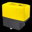
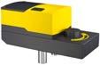
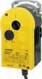
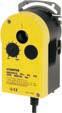
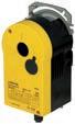
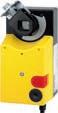
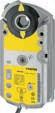
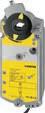
Features
• Actuates final control elements such as butterfly valves and air dampers
• For controllers with a switching output (3-point)
• Synchronous motor with two limit switches and two auxiliary switches
• Feedback potentiometer with path shut-off
• Maintenance-free metal gearbox
• Positions the control unit to any intermediate position
• Three cable inlets with M16 × 1.5 cable gland for 4.5 to 10 mm cable diameter
Technical data
Power supply
Parameters
Ambient conditions
Design
Standards, directives
Power supply 230 VAC ±10%, 50…60 Hz
Power supply 24 VAC ±20%, 50…60 Hz
Angle of rotation1) 90°
Nominal torque 30 Nm
Holding torque 60 Nm
Running time for 90° 120 s (de-energised when idle)
Admissible damper area2) 10 m²
Path shut-off Limit switch (NC/NO changeover switch)
Switch rating max. 6(2)A, 250 VAC
Potentiometer 1 kΩ, loop current 0,2 μA (recommended), max. 0.5 W
Ambient temperature3) −15…60 °C
Ambient humidity 5…95% rh
Storage and transport temperature−30…70 °C
Cable inlet
3 pcs, M16 × 1.5
Screw terminals For electrical cables up to 1.5 mm²
Housing material Cast aluminium, RAL 9005
Cover: powder-coated aluminium, RAL 1018
Transmission system Hardened steel
Dimensions W × H × D 86 × 167 [137] × 153 mm [ ]: Height without end shaft
Weight 2.3 kg
Type of protection4) IP65 (EN 60529)
Protection class I (EN 60730-1)
Degree of contamination III
1) 90° angle of rotation of end shaft is adjustable from 10° to 330° using a switching cam (from any starting point).
2) Admissible damper surface area: The recommended admissible damper surface area refers to equal-sided, smooth-running air dampers
3) At temperatures under 0 °C, use heating resistor (accessory) With a media temperature of up to 110 °C in the final control element, an ambient temperature up to 60 °C is permitted. With a media temperature above 110 °C, the ambient temperature must not exceed 55 °C
4) IP65 protection only with M16 × 1.5 cable gland.

CE conformity according toEMC Directive 2014/30/EUEN 61326-1
EN 55011 Group 1, Class B Low-Voltage Directive 2014/35/EUEN 60730-1, EN 60730-2-14
RoHS-D 2011/65/EU & 2015/863/EU
EN IEC 63000
Overview of types
Type
VoltagePower consumption with 50 Hz
ADM333HF120230 VAC5.3 W
ADM333HF12224 VAC5.8 W
Accessories
Type
Description
Features
Synchronous motor: 2 limit switches, 2 auxiliary switches, potentiometer feedback
Synchronous motor: 2 limit switches, 2 auxiliary switches, potentiometer feedback
0510510010Heating resistor for ADM 333, 230 V, 3 W
0510510012Heating resistor for ADM 333, 24 V, 3 W
0510420020Parallel relay for ADM 333, 230 V with 3-point activation
0510240031Mounting kit for ADM 333 with butterfly valve DEF, DN 25…65
0510240032Mounting kit for ADM 333 with butterfly valve DEF, DN 80…125
0510240033Mounting kit for ADM 333 with butterfly valve DEF, DN 150…200
0510240041Mounting kit for ADM 333 with butterfly valve DEF, DN 25…65, hand lever
0510240042Mounting kit for ADM 333 with butterfly valve DEF, DN 80…125, hand lever
0510240043Mounting kit for ADM 333 with butterfly valve DEF, DN 150…200, hand lever
Features
• Actuation of final control elements such as butterfly valves, gates and air dampers
• For controllers with continuous output (0(2)...10 V/0(4)...20 mA)
• Synchronous motor with two limit switches and integrated positioner
• Menu-led configuration via an internal TFT display
• Positional feedback signal via 0(2)…10 V/0(4)…20 mA
• Potential-free fault signal output
• Configurable direction of operation
• Control unit to be actuated can be moved to any intermediate position
• Maintenance-free metal gearbox
• Three cable inlets with M16 × 1.5 cable gland for cables Ø 4.5 to 10 mm
Technical data
Power supply
Parameters
Ambient conditions
Construction
Voltage measurement
Power consumption with 50 Hz4 VA
Power consumption in stand-by modeMANUAL: 1.26 VA AUTO: 0.4 VA
Angle of rotation1) 90°
Nominal torque 30 Nm
Holding torque 20 Nm
Running time for 90° 60 s
Admissible damper area2) 10 m²
Control signal3)
Positional feedback signal4)
Fault signal output
Ambient temperature5) -15…60 °C
Ambient humidity 5…95% rh
Storage and transport temperature-30...70 °C
Cable inlet
3 pieces, M16 × 1.5
Screw terminals For electrical cables up to 1.5 mm²
Housing material
Cast aluminium, RAL 9005
Cover: powder-coated aluminium, RAL 1018
Transmission system Hardened steel
Dimensions W × H × D 86 × 167 [137] × 153 mm [ ]: Height without end shaft
Weight 2.3 kg
1) Angle of rotation of end shaft is adjustable from min. 10° to max. 330° by means of a switching cam (starting point is freely selectable)
2) Admissible damper area: The recommended admissible damper area refers to equal-sided, smooth-running air dampers
3) Control signal is protected against reversed polarity
4) Positional feedback signal is protected against reversed polarity and excess voltage
5) At temperatures under 0 °C, use heating resistor (accessory) With a media temperature of up to 110 °C in the final control element, an ambient temperature of up to 60 °C is permitted. With a media temperature above 110 °C, the ambient temperature must not exceed 55 °C

Standards, directives
Type of protection6)
IP65 (EN 60529)
Protection class I (EN 60730-1)
Degree of contamination III
CE conformity according toEMC Directive 2014/30/EUEN 61000-6-1, EN 61000-6-2
EN 61000-6-3, EN 61000-6-4
Low-Voltage Directive 2014/35/EUEN 60730-1, EN 60730-2-14
RoHS-D 2011/65/EU & 2015/863/EU EN IEC 63000
Overview of types
Type Features
ADM333SF122Synchronous motor with positioner
Accessories
Type Description
0510510012Heating resistor for ADM 333, 24 V, 3 W
0510240031Mounting kit for ADM 333 with butterfly valve DEF, DN 25…65
0510240032Mounting kit for ADM 333 with butterfly valve DEF, DN 80…125
0510240033Mounting kit for ADM 333 with butterfly valve DEF, DN 150…200
0510240041Mounting kit for ADM 333 with butterfly valve DEF, DN 25…65, hand lever
0510240042Mounting kit for ADM 333 with butterfly valve DEF, DN 80…125, hand lever
0510240043Mounting kit for ADM 333 with butterfly valve DEF, DN 150…200, hand lever
Features
• For operating control units such as control valves, butterfly valves etc.
• For controllers with a switching output (2-point or 3-point control)
• 15 Nm nominal torque and holding torque
• Synchronous motor with electronic control unit and load-dependent cut-off
• Low operating noise
• Direction of operation and running time can be set using coding switches
• Gear unit can be disengaged for manual adjustment
• Electrical parallel operation of up to five actuators possible
• Numerous adapters enable the unit to be fitted onto defined non-SAUTER control valves
• Maintenance-free gearbox made of plastic and steel, and gearbox base-plates made of steel
• Mounting columns made of aluminium
Technical data
Power supply
ADM322(H, P)F120
ADM322(H, P)F122
Parameters
Ambient conditions
Construction
Standards and directives
Power supply 24 VAC ± 20%, 50…60 Hz
Power supply 24 VDC −10%…20%
Power supply 230 VAC ± 15%
Connections (screw terminals) Max. 1.5 mm2
Power consumption
Power consumption
Operating noise1)
< 2.2 W
< 2.5 W
< 30 dB(A) (loaded)
Running time for 90° 120 (240) s
Response time < 200 ms
Angle of rotation Max. 95°
Rotational torque and holding torque15 Nm
Operating temperature
−20…55 °C
Storage and transport temperature−40…80 °C
Air humidity without condensation5…85% rh
Dimensions W × H × D 194 × 116 × 86 mm
Weight 1.5
Fitting position
Housing
Housing material
Cable inlet
Type of protection
Vertically upright to horizontal, not fitted upside down
Three-part
Flame retardant yellow/black plastic
With break-outs, for metric screw fittings M20×1.5
IP54 (EN 60529)
Protection class II (EN 60730-1), EN 60730-2-14 III (EN 60730-1), EN 60730-2-14
CE conformity according toEMC Directive 2014/30/EUEN 61000-6-1
EN 61000-6-2
EN 61000-6-3
EN 61000-6-4
Low-Voltage Directive 2014/35/EUEN 60730-1
1) Operating noise with the slowest running time
EN 60730-2-14

Overview of types
Type Nominal voltage
ADM322F120230 V~
Over-voltage categories III
Degree of contamination II
Max. altitude 2000 metres
Machinery Directive 2006/42/EC (according to Appendix II, 1B)
Version
ADM322F12224 V~/= –
ADM322HF120230 V~
ADM322HF12224 V ~/=
ADM322PF120230 V~
ADM322PF12224 V~/=
Accessories
Type Description
0510600001Cable module, 1.2 m, 3-wire, PVC
0510600002Cable module, 1.2 m, 3-wire, halogen-free
0510600003Cable module, 1.2 m, 6-wire, PVC
0510600004Cable module, 1.2 m, 6-wire, halogen-free
0510600005Cable module, 5 m, 3-wire, PVC
0510600006Cable module, 5 m, 3-wire, halogen-free
0510600007Cable module, 5 m, 6-wire, PVC
0510600008Cable module, 5 m, 6-wire, halogen-free
EN ISO 12100:2018
Auxiliary contacts
Auxiliary contacts
Potentiometer
Potentiometer
0510240013ADM322 mounting kit with M3R, M4R, MH32, MH42
0510240014ADM322 fitting kit with DEF DN20...65
0510240015ADM322 fitting kit with DEF DN80...100
0510390002Adapter set for control valve, Honeywell, DZ/ZR valves only
0510390003Adapter set for control valve, Danfoss
0510390004Adapter set for Caleffi control valve
0510390005Adapter set for control valve, Coster
Features
• For operating control units such as control valves, butterfly valves etc.
• For controllers with a continuous output
• 15 Nm nominal torque and holding torque
• ADM322SF122: Synchronous motor with electronic control unit and load-dependent cut-off
• ADM322SF152: Brushless DC motor with SUT (SAUTER Universal Technology) electronic control unit and electronic, load-dependent cut-off
• Low operating noise
• Automatic recognition of applied control signal
• With the built-in absolute distance measurement system, the position is always maintained in the case of power failure
• The direction of operation, running time and control signal (voltage/current) can be adjusted via coding switches
• High-speed variant ADM322SF152 with 30 s or 60 s for angle of rotation 90°
• Gear unit can be disengaged for manual adjustment
• Easy re-initialisation using a coding switch
• Electrical parallel operation of up to five actuators possible
• Numerous adapters enable the unit to be fitted onto defined non-SAUTER control valves
• ADM322SF152: Integrated forced operation can be set via coding switches (with selectable direction of operation)
• Maintenance-free gearbox made of plastic and steel, and gearbox base-plates made of steel
• Mounting columns made of aluminium
Technical data
Power supply
Parameters
Power supply
Operating noise1)
24 VDC −10%…20% 24 VAC ± 20% (50…60 Hz)
< 30 dB(A) (loaded)
Response time < 200 ms
Angle of rotation
Max. 95°
Rotational torque and holding torque15 Nm
ADM322SF122 positionerControl signal y 0...10 V, Ri ≥ 50 kΩ, 0...20 mA, Ri ≤ 50 Ω 2...10 V (4...20 mA)
Positional feedback signal y0 0…10 V, load ≥ 5 kΩ
Starting point U0 0 or 10 V
Starting point I0 0 or 20 mA
Control span ΔU 10 V
Switching range Xsh 130 mV, 0.26 mA
Control span ΔI 20 mA
Max. admissible line resistance3 Ω
ADM322SF152 positionerControl signal y 0...10 V, Ri ≥ 50 kΩ, 4...20 mA, Ri ≤ 50 Ω
Positional feedback signal y0 0…10 V, load ≥ 5 kΩ
Starting point U0 0 or 10 V
Starting point I0 4 or 20 mA
Control span ΔU 10 V
Switching range Xsh 130 mV, 0.26 mA
Control span ΔI 20 mA
1) Operating noise with the slowest running time

Ambient conditions
Construction
Max. admissible line resistance3 Ω
Operating temperature
−20…55 °C
Storage and transport temperature−40…80 °C
Humidity without condensation5…85% rh
Connection terminals
Cable inlet
Screw terminals, max. 1.5 mm²
With break-outs, for metric screw fittings M20 × 1.5
Housing Three-part
Housing material
Flame-retardant yellow/black plastic
Dimensions W × H × D 194 × 166 × 86 mm
Fitting position
Standards and directives
Vertically upright to horizontal, not fitted upside down
Weight 1.5 kg
Type of protection IP54 (EN 60529)
Protection class III (EN 60730-1), EN 60730-2-14
CE conformity according toEMC Directive 2014/30/EUEN 61000-6-1, EN 61000-6-2 EN 61000-6-3, EN 61000-6-4
Low-Voltage Directive 2014/35/EUEN 60730-1 EN 60730-2-14
Over-voltage categories III
Degree of contamination II
Max. altitude 2000 m
Machinery Directive 2006/42/EC (according to Appendix II, 1B)
EN ISO 12100:2018
Overview of types
Type Description
ADM322SF122Rotary
Accessories
0510600001Cable module, 1.2 m, 3-wire, PVC 0510600002Cable module, 1.2 m, 3-wire, halogen-free 0510600003Cable module, 1.2 m, 6-wire, PVC
0510600004Cable module, 1.2 m, 6-wire, halogen-free 0510600005Cable module, 5 m, 3-wire, PVC
0510600006Cable module, 5 m, 3-wire, halogen-free 0510600007Cable module, 5 m, 6-wire, PVC
0510600008Cable module, 5 m, 6-wire, halogen-free 0313529001Split-range unit for setting sequences
0510240013ADM322 mounting kit with M3R, M4R, MH32, MH42
0510240014ADM322 fitting kit with DEF DN20...65
Type Description
0510240015ADM322 fitting kit with DEF DN80...100
0510390002Adapter set for control valve, Honeywell, DZ/ZR valves only
0510390003Adapter set for control valve, Danfoss
0510390004Adapter set for Caleffi control valve
0510390005Adapter set for control valve, Coster
ADM322SF152 only
Type Description
05004200024…20 mA feedback module for valve actuators AVM321S and AVM322S
0500570003Constant 230 V module for valve actuators AVM321S and AVM322S
Features
• For controllers with switching output (2- and 3-point)
• Self-centring spindle adapter
• Gear unit can be disengaged to position the damper and for manual adjustment
• Synchronous motor with electronic activation and cut-out
• Maintenance-free
• Suitable for all fitting positions
Technical data
Parameters

Ambient conditions
Function
Construction
Standards and directives
Angle of rotation
Max. 95°
Admissible damper shaft Ø 8...16 mm, □ 6,5...12.5 mm
Admissible damper shaft (hardness)Max. 300 HV
Operating noise < 30 dB (A)
Response time 200 ms
Ambient temperature1) –20...65 °C
Ambient humidity 5...85% rh, no condensation
Control 2-/3-point
Weight
Housing
0.7 kg
Lower section black, upper section yellow
Housing material Fire-retardant plastic
Power cable 1.2 m long, 3 × 0.75 mm²
Type of protection
IP54 (EN 60529)
Protection class 24 V III (EN 60730)
Protection class 230 V II (EN 60730)
CE conformity according toEMC Directive 2014/30/EUEN 61000-6-1, EN 61000-6-2 EN 61000-6-3, EN 61000-6-4
Directive 2006/95/EC EN 1050
Low-Voltage Directive 2014/35/EU2) EN 60730-1, EN 60730-2-14
Over-voltage category III
Degree of contamination II
Overview of types
1) Operating time approx. 80% up to 65 °C, 100% up to 55 °C
2) Only for ASM1*5F1*0
Accessories
Type Description
0361977002Assembly materials for M3R, M4R, MH32R/F, MH42R with ASM 105, 115 0372145001Auxiliary change-over contacts, single 0372145002Auxiliary change-over contacts, double 0372286001Potentiometer, 130 Ω 0372286002Potentiometer, 1000 Ω 0372286003Potentiometer, 5000 Ω 0372300001Torsion protection, long (230 mm)
0372301001Spindle adaptor for squared end hollow profile (x 15 mm), pack of 10 pcs. 0372320001Hexagon key as visualisation for position indicator
A Auxiliary change-over contacts: Infinitely variable 0...90°, admissible load 5(2) A, 24...230 V
A Potentiometers: Only one potentiometer or one set of auxiliary contacts can be fitted for each actuator
Features
• For controllers with switching (2- and 3-point) or continuous output (0…10 V)
• Self-centring spindle adapter
• Gear unit can be disengaged to position the damper and for manual adjustment
• Stepping motor with electronic activation and cut-out
• Maintenance-free
• Intelligent adaptation of rotation angle, incl. feedback adjustment
• Free configuration using the CASE Drive PC tool
• Suitable for all fitting positions
Technical data
Power supply
Parameters
Positioner
Ambient conditions
Construction
Standards and directives
CE conformity
Power supply 24 VAC ±20%, 51...60 Hz
Power supply 24 VDC ±20%
Angle of rotation
Max. 95°
Admissible damper shaft Ø 8...16 mm, □ 6,5...12.5 mm
Admissible damper shaft (hardness)Max. 300 HV
Operating noise < 30 dB (A)
Response time 200 ms
Control signal y 0...10 V, Ri > 100 kΩ
Positional feedback signal y0 0...10 V; load > 10 kΩ
Starting point U0 0 or 10 V
Control span ΔU 10 V
Switching range Xsh 200 mV
Ambient temperature –20...55 °C
Ambient humidity < 95% rh, no condensation
Weight
Housing
0.7 kg
Lower section black, upper section yellow
Housing material Fire-retardant plastic
Power cable 1.2 m long, 5 × 0.5 mm²
Type of protection
IP54 (EN 60529)
Protection class III (IEC 60730)
EMC Directive 2014/30/EUEN 61000-6-1
EN 61000-6-3
EN 61000-6-4
Directive 2006/95/EC EN 1050
Overview of types
Type Rotational torque and holding torque (Nm)
Running time for 90° Power consumption
ASM105SF1325 35/60/120 s 5.0 W, 9.0 VA
ASM115SF13210 60/120 s 4.8 W, 8.7 VA

Accessories
Type Description
0313529001Split-range unit for setting sequences
0361977002Assembly materials for M3R, M4R, MH32R/F, MH42R with ASM 105, 115
0372145001Auxiliary change-over contacts, single 0372145002Auxiliary change-over contacts, double 0372286001Potentiometer, 130 Ω
0372286002Potentiometer, 1000 Ω 0372286003Potentiometer, 5000 Ω 0372300001Torsion protection, long (230 mm)
0372301001Spindle adaptor for squared end hollow profile (x 15 mm), pack of 10 pcs.
0372320001Hexagon key as visualisation for position indicator
A Auxiliary change-over contacts: Infinitely variable 0...90°, admissible load 5(2) A, 24...230 V
A Potentiometers: Only one potentiometer or one set of auxiliary contacts can be fitted for each actuator
Features
• For controllers with switching (2- and 3-point) or continuous output (0…10 V)
• Brushless motor with electronic activation and cut-out
• Intelligent adaptation of rotation angle
• Electronic force-dependent cut-off
• Direction of rotation selection via DIP switch
• Pulse length correction in 3-point operation, i.e. internal adjustment of start-up time
• Self-centring spindle adapter
• Gear unit can be disengaged to position the damper and for manual adjustment
• Maintenance-free
• Fitting: Vertically upright to horizontal, not suspended
Technical data
Power supply
Parameters
Positioner
Ambient conditions
Construction
Power supply 24 VAC ±20%, 50…60 Hz
Power supply 24 VDC +20%, -10%
Angle of rotation
Max. 95°
Admissible damper shaft Ø 8…16 mm, □ 6.5…12.5 mm
Admissible damper shaft (hardness)Max. 300 HV
Operating noise (unloaded)< 49 dB (A)
Response time 10 ms (electrically compensated)
Positioning signal y 0…10 V / 2…10 V, Ri = 100 kΩ, 0…20 mA / 4…20 mA, Ri = 500 Ω
Positional feedback signal y0 0...10 V, load > 10 kΩ
Starting point U0 0 or 10 V / 2 or 10 V
Starting point I0 0 or 20 mA / 4 or 20 mA
Control span ΔU 10 V
Switching range Xsh 100 mV
Control span ΔI 20 mA
Switching range Xsh 0.1 mA
Operating temperature −20…55 °C
Storage and transport temperature−30…65 °C
Ambient humidity 5…85% rh, no condensation
Dimensions W × H × D 70 × 63 × 133 mm
Weight 0.7 kg
Housing
Housing material
Standards, directives

Lower section black, upper section yellow
Flame-retardant plastic
Power cable 1.2 m long, 6 × 0.5 mm²
Type of protection
IP54 (EN 60529)
Protection class III (EN 60730)
CE conformity EMC Directive 2014/30/EUEN 61000-6-1, EN 61000-6-2 EN 61000-6-3, EN 61000-6-4
UL and CAN compliance (ASM105SF152U only)
Overview of types
Electrical safety
UL 60730-1 Part 1, UL 60730-2-14 Part 2, CAN/CSA-E60730-1:02 Part 1 and Annex 1
/ Rotational torque and holding torque: Holding torque is typically 1.5 Nm when the actuator is without power
Type Rotational torque and holding torque Running time for 90° Power consumption
ASM105SF1525 Nm 3 s 6.0 W, 8.5 VA
ASM115SF15210 Nm 6 s 6.5 W, 9.0 VA
ASM105SF152U3 Nm 3 s 6.0 W, 8.5 VA
Accessories
Type Description
0313529001Split-range unit for setting sequences
0361977002Assembly materials for M3R, M4R, MH32R/F, MH42R with ASM 105, 115 0372300001Torsion protection, long (230 mm)
0372301001Spindle adaptor for squared end hollow profile (x 15 mm), pack of 10 pcs.
A The UL compliances of the ASM105SF152U do not apply to the accessories
Features
• For operating air dampers, shut-off dampers, butterfly valves and multi-leaf dampers
• For controllers with switching (2- and 3-point) output
• Synchronous motor with electronic activation and cut-out
• Maintenance-free gear unit
• Electronic end position detector and motor cut-off
• Self-centring spindle adapter for fitting onto damper spindle
• Gear unit can be disengaged to position the damper and for manual adjustment
• Suitable for all fitting positions
• Threaded holes (M5) for fitting to bracket
• Version with halogen-free cable on demand
Technical data
Power supply
Parameters
Ambient conditions
Construction
Power supply 230 VAC ±15%, 50...60 Hz
Power supply 24 VAC ±20%, 50...60 Hz
Rotational torque and holding torque18 Nm
Running time for 90° 120 s
Angle of rotation
Max. 95°
Admissible damper shaft Ø 12...20 mm, □ 10...16 mm
Admissible damper shaft (hardness)Max. 300 HV
Operating noise < 30 dB (A)
Response time 200 ms
Ambient temperature −20...55 °C
Ambient humidity < 95% rh, no condensation
Weight 1.2 kg
Housing
Housing material
Standards, directives
Lower section black, upper section yellow
Flame-retardant plastic
Power cable 1.2 m long, 3 × 0.75 mm²
Type of protection
IP40 (EN 60529), IP43 (EN 60529), IP54 (EN 60529), IP55 (EN 60529)
Protection class 230 V II (EN 60730)
Protection class 24 V III (EN 60730)
EMC Directive 2014/30/EUEN 61000-6-1, EN 61000-6-2 EN 61000-6-3, EN 61000-6-4
Low-Voltage Directive 2014/35/EUEN 60730-1, EN 60730-2-14
Over-voltage categories III
Degree of contamination II
Mode of operation
Overview of types

Type 1 AB (EN 60730)
Type 1 C (EN 60730)
Software A (EN 60730)
A Powerconsumptionwhenidle:
A ASM124F120: 0.5 W, 5.1 VA
A ASM124F122: 0.03 W, 0.4 VA
Accessories
Type Description
0361977001Assembly materials for M3R, M4R, MH32F, MH42F with ASM 124
0370059000Clamping lever for shaft, Ø 8...18 mm
0370990001Auxiliary change-over contacts, single 0370990002Auxiliary change-over contacts, double 0370992001Potentiometer, 2000 Ω, 1 W
0370992002Potentiometer, 130 Ω, 1 W
0372200001Fitting bracket
0372201001Spindle extension with coupling
0372202001Lever, fitting strip
0372203001Driver axle for auxiliary contacts
0372204001Spindle for clamping lever 0370059000
0372455001Assembly part; DEF DN25...65 for ASM 124/134
0372455002Assembly part; DEF DN80...100 for ASM 124; DN125 for ASM 134
A Auxiliary change-over contacts: Infinitely variable 0...90°, admissible load 5(2) A, 24...230 V
ASM134F130
Features
• For operating air dampers, shut-off dampers, butterfly valves and multi-leaf dampers
• For controllers with a switching (3-point) output
• Self-centring spindle adapter
• Gear unit can be disengaged to position the damper and for manual adjustment
• Stepping motor with electronic activation and cut-out
• Direction of rotation changed by transposing the connections
• Suitable for all fitting positions
• Maintenance-free
• Version with halogen-free cable on demand
Technical data
Power supply
Parameters
Ambient conditions
Construction
Standards, directives
Power supply 230 V~, ±15%, 50 Hz
Power consumption 3.7 W, 4.7 VA
Rotational torque and holding torque30 Nm
Running time for 90° 120/240 s
Angle of rotation Max. 95°
Admissible damper shaft Ø 12...20 mm, □ 10...16 mm
Admissible damper shaft (hardness)Max. 300 HV
Operating noise < 30 dB (A)
Response time 200 ms
Ambient temperature −20...55 °C
Ambient humidity < 95% rh, no condensation
Weight 1.8 kg
Housing
Lower section black, upper section yellow
Housing material Flame-retardant plastic
Power cable 1.2 m long, 3 × 0.75 mm²
Type of protection
IP40 (EN 60529)
IP54 (EN 60529)
IP55 (EN 60529)
Protection class II (IEC 60730)
EMC Directive 2014/30/EUEN 61000-6-1, EN 61000-6-2 EN 61000-6-3, EN 61000-6-4
Low-Voltage Directive 2014/35/EUEN 60730-1, EN 60730-2-14
Over-voltage categories III
Degree of contamination III
Mode of operation
Overview of types

Type 2 B (EN 60730)
Software A (EN 60730)
Type Rated power during continuous operation
Power consumption when idle
ASM134F1303.7 W, 4.7 VA 1.1 W, 2.7 VA
Accessories
Type Description
0361977001Assembly materials for M3R, M4R, MH32F, MH42F with ASM 124
0370059000Clamping lever for shaft, Ø 8...18 mm
0370990001Auxiliary change-over contacts, single 0370990002Auxiliary change-over contacts, double 0370992001Potentiometer, 2000 Ω, 1 W
0370992002Potentiometer, 130 Ω, 1 W
0372200001Fitting bracket
0372201001Spindle extension with coupling 0372202001Lever, fitting strip
0372203001Driver axle for auxiliary contacts
0372204001Spindle for clamping lever 0370059000
0372455001Assembly part; DEF DN25...65 for ASM 124/134
0372455002Assembly part; DEF DN80...100 for ASM 124; DN125 for ASM 134
0372455003Assembly part; DEF DN150...200 for ASM 134
A Auxiliary change-over contacts: Infinitely variable 0...90°, admissible load 5(2) A, 24...230 V
Features
• For operating air dampers, shut-off dampers, butterfly valves and multi-leaf dampers
• For controllers with switching (2- and 3-point) or continuous output (0…10 V)
• Self-centring spindle adapter
• Gear unit can be disengaged to position the damper and for manual adjustment
• Stepping motor with electronic activation and cut-out
• Maintenance-free
• Intelligent adaptation of rotation angle, incl. feedback adjustment
• Direction of rotation changed by transposing the connections
• Suitable for all fitting positions
• Version with halogen-free cable on demand
Technical data
Power supply
Parameters
Power supply 24 VAC ±20%, 50...60 Hz
Power supply 24 VDC1) ±20%
Angle of rotation
Positioner
Ambient conditions
Construction
Standards, directives
Max. 95°
Admissible damper shaft (hardness)Max. 300 HV
Operating noise < 30 dB(A)
Response time 200 ms
Control signal 0...10 V, Ri > 100 kΩ
Positional feedback signal 0...10 V, load > 10 kΩ
Starting point U0 0 or 10 V
Control span ΔU 10 V
Switching range Xsh 200 mV
Ambient temperature −20...55 °C
Ambient humidity < 95% rh, no condensation
Weight
Housing
1.6 kg
Lower section black, upper section yellow
Housing material Flame-retardant plastic
Power cable 1.2 m long, 2 × 0.75 mm²
Type of protection
IP40 (EN 60529), IP43 (EN 60529), IP54 (EN 60529)
Protection class III (IEC 60730)
EMC Directive 2014/30/EUEN 61000-6-1, EN 61000-6-2 EN 61000-6-3, EN 61000-6-4
Mode of operation

Type 1 AB (EN 60730)
Type 1 C (EN 60730)
Software A (EN 60730)
1) 24 V= only for control signals 0...10 V
Overview of types
Type Nominal torqueHolding torqueRunning time for 90° Power consumptionAdmissible damper shaft
ASM124SF13215 Nm15 Nm60, 120 s2.4 W, 4.4 VAØ 12...20 mm, □ 10...16 mm
ASM134SF13230 Nm30 Nm120, 240 s2.4 W, 4.3 VAØ 12...20 mm, □ 10...16 mm
A Powerconsumptionwhenidle:
A ASM124SF132: 0.25 W, 0.46 VA
A ASM134SF132: 0.26 W, 0.48 VA
Accessories
Type Description
0313529001Split-range unit for setting sequences
0361977001Assembly materials for M3R, M4R, MH32F, MH42F with ASM 124
0370059000Clamping lever for shaft, Ø 8...18 mm
0370990001Auxiliary change-over contacts, single 0370990002Auxiliary change-over contacts, double 0370992001Potentiometer, 2000 Ω, 1 W 0370992002Potentiometer, 130 Ω, 1 W 0372200001Fitting bracket
0372201001Spindle extension with coupling 0372202001Lever, fitting strip
0372203001Driver axle for auxiliary contacts 0372204001Spindle for clamping lever 0370059000
0372455001Assembly part; DEF DN25...65 for ASM 124/134
0372455002Assembly part; DEF DN80...100 for ASM 124; DN125 for ASM 134
0372455003Assembly part; DEF DN150...200 for ASM 134
A Auxiliary change-over contacts: Infinitely variable 0...90°, admissible load 5(2) A, 24...230 V Valves, control valves, dampers, actuators | Damper and rotary actuators
Features
• For operating air dampers, shut-off dampers, butterfly valves and multi-leaf dampers
• For controllers with switching (2- and 3-point) output
• Self-centring spindle adapter
• Manual adjustment using hexagon socket, including locking of gear unit
• Maintenance-free
• Suitable for all fitting positions
Technical data
Power supply
A ASF112F220, ASF112F222: Double auxiliary contacts 6(2) A; 24...250 V~ with cable 0.9 m; 6 × 0.75 mm² Valves, control valves, dampers, actuators | Damper and rotary actuators
Parameters
Ambient conditions
Construction
Standards and directives
Power supply 230 VAC ±10%, 50...60 Hz
Power supply 24 VAC ±20%, 50...60 Hz
Power supply 24...48 V= ±20%
Rotational torque and holding torque7 Nm
Angle of rotation Max. 95°
Admissible damper shaft Ø 6.4...20.5 mm, □ 6.4...13 mm
Running time for 90° motor90 s
Running time for 90° spring15 s
Ambient temperature –32...55 °C
Ambient humidity 5...95% rh, no condensation
Housing
Cast aluminium
Power cable 0.9 m, 0.75 mm²
Type of protection
IP54 (EN 60529), suspended IP42 (EN 60529), not suspended
Protection class 24 V III (EN 60730)
Protection class 230 V II (EN 60730)
EMC Directive 2014/30/EUEN 61000-6-2, EN 61000-6-3
Low-Voltage Directive 2014/35/EUEN 60730-1, EN 60730-2-14
Degree of contamination II
Over-voltage categories III
Overview of types
Type Control functionVoltage Power consumptionWeight
ASF112F1202-point
230 V~ 4.5 W, 7.0 VA1.2 kg
ASF112F1222-point 24 V~/24...48 V=3.5 W, 5.0 VA1.2 kg
ASF112F2202-point 230 V~ 4.5 W, 7.0 VA1.3 kg
ASF112F2222-point 24 V~/24...48 V=3.5 W, 5.0 VA1.3 kg
ASF113F1223-point 24 V~/24...48 V=3.5 W, 5.0 VA1.2 kg

Accessories
Type Description
0372245001Lever adaptor for converting rotation into stroke
0372245002Lever adaptor for converting rotation into stroke, with carrier plate for mounting on wall or plinth
0510240001Assembly kit for VK**/BK** ball valves as spare part and as accessory for rotary actuators ASF 112, 113 from index B Valves,
Valves, control valves, dampers, actuators | Damper and rotary actuators
Features
• For operating air dampers, shut-off dampers, butterfly valves and multi-leaf dampers
• For controllers with a continuous output (0...10 V)
• Self-centring spindle adapter
• Manual adjustment using hexagon socket, including locking of gear unit
• Maintenance-free
• Suitable for all fitting positions
Technical data
Power supply
Parameters
Positioner
Setting range
Ambient conditions
Construction
Standards and directives
Power supply 24 VAC ±20%, 50...60 Hz
Power supply 24...48 V= ±20%
Power consumption 3.5 W, 5.0 VA
Running time for 90° motor90 s
Running time for 90° spring15 s
Rotational torque 7 Nm
Holding torque 7 Nm
Angle of rotation Max. 95°
Admissible damper shaft Ø 6.4...20.5 mm, □ 6.4...13 mm
Admissible damper surface area1) 1.5 m2
Control signal 0...10 V, Ri = 100 kΩ
Positional feedback signal 0...10 V (0...100%)
Admissible load > 10 kΩ
Switching range Xsh 0.2 V
Starting point U0 0 V
Control span ΔU 10 V
Ambient temperature –32...55 °C
Ambient humidity < 95% rh
Weight 1.3 kg
Housing Cast aluminium
Power cable 0.9 m, 4 × 0.75 mm²
Type of protection
IP54 (EN60529), suspended IP 42 (EN 60529), not suspended
Protection class III (IEC 60730)
Degree of contamination II
Over-voltage categories III
Low-Voltage Directive 2014/35/EUEN 60730-1, EN 60730-2-14
EMC Directive 2014/30/EUEN 61000-6-2, EN 61000-6-3

Overview of types
Type Features
ASF113SF122Damper actuator with spring return and positioner
1) Recommended value for smooth-running air dampers
Accessories
Type Description
0372245001Lever adaptor for converting rotation into stroke
0372245002Lever adaptor for converting rotation into stroke, with carrier plate for mounting on wall or plinth
0510240001Assembly kit for VK**/BK** ball valves as spare part and as accessory for rotary actuators ASF 112, 113 from index B Valves,
Features
• For operating air dampers, shut-off dampers, butterfly valves and multi-leaf dampers
• For controllers with switching (2- and 3-point) output
• Self-centring spindle adapter
• Manual adjustment using hexagon socket, including locking of gear unit
• Wear-free brushless motor
• Maintenance-free
• Change direction of rotation by simply turning the actuator
• Suitable for all fitting positions
Technical data
Power supply
Parameters
Ambient conditions
Construction
Standards and directives
Power supply 24 VAC ±20%, 50...60 Hz
Power supply 230 VAC ±10%, 50...60 Hz
Power supply 24...48 V= ±20%
Running time for 90° motor90 s
Running time for 90° spring15 s
Rotational torque and holding torque18 Nm
Angle of rotation Max. 90°
Admissible damper shaft Ø 8...25 mm, □ 6...18 mm
Ambient temperature −32...55 °C
Ambient humidity 5...95% rh
Housing
Cast aluminium
Power cable 0.9 m, 0.75 mm²
Type of protection IP54 (EN60529), suspended IP42 (EN 60529), not suspended
Protection class 24 V III (EN 60730)
Protection class 230 V II (EN 60730)
EMC Directive 2014/30/EUEN 61000-6-2, EN 61000-6-3
Low-Voltage Directive 2014/35/EUEN 60730-1, EN 60730-2-14
Over-voltage categories III
Degree of contamination II
Overview of types
ASF122F1202-point
ASF122F1222-point
ASF122F2202-point
ASF122F2222-point
ASF123F1223-point
A ASF122F220, ASF122F222: With double auxiliary contacts 6(2) A; 24...250 V~; with cable 0.9 m;

Accessories
Type Description
0370997001Lever adaptor for converting rotation into stroke
0370998001Lever adaptor for converting rotation into stroke, with carrier plate for mounting on wall or plinth
0378113001Assembly parts; DEF DN 25…100 for ASF122/123
Valves, control valves, dampers, actuators | Damper and rotary actuators
Features
• For operating air dampers, shut-off dampers, butterfly valves and multi-leaf dampers
• For controllers with a continuous output (0...10 V)
• Self-centring spindle adapter
• Manual adjustment using hexagon socket, including locking of gear unit
• Wear-free brushless motor
• Maintenance-free
• Change direction of rotation by simply turning the actuator
• Suitable for all fitting positions
Technical data
Power supply
Parameters
Positioner
Setting range
Ambient conditions
Construction
Standards and directives
Power supply 24...48 V= ±20%
Power consumption 5.4 W, 7.5 VA
Running time for 90° motor90 s
Running time for 90° spring15 s
Rotational torque and holding torque18 Nm
Angle of rotation
Max. 95°
Admissible damper shaft Ø 8...25 mm, □ 6...18 mm
Control signal 0...10 V, Ri = 100 kΩ
Positional feedback signal 0...10 V (0...100%)
Admissible load > 10 kΩ
Switching range Xsh 0.2 V
Starting point U0 0 V
Control span ΔU 10 V
Ambient temperature –32...55 °C
Ambient humidity < 95% rh
Weight 2 kg
Housing Cast aluminium
Power cable 0.9 m, 4 × 0.75 mm²
Type of protection1)
IP54 (EN60529), suspended
IP42 (EN 60529), not suspended
Protection class III (IEC 60730)
EMC Directive 2014/30/EUEN 61000-6-2, EN 61000-6-3
Low-Voltage Directive 2014/35/EUEN 60730-1, EN 60730-2-14
Over-voltage categories III
Degree of contamination II

Overview of types
Type Features
ASF123SF122Damper actuator with spring return and positioner
1) Depending on fitting position, ensure IP54
Accessories
Type Description
0370997001Lever adaptor for converting rotation into stroke
0370998001Lever adaptor for converting rotation into stroke, with carrier plate for mounting on wall or plinth
0378113001Assembly parts; DEF DN 25…100 for ASF122/123
The standard in building automation.
SAUTER modulo 6 offers unprecedented performance in terms of data points, memory capacity and processing speed, all with minimal space requirements. As an alternative to smartphone operation, the range also includes a local operating unit (LOI) with a highresolution graphical colour display. The LOI is compatible with all available I/O modules and offers priority operation decoupled from the station. modulo 6 connects to the cloud and IoT just as securely as with the existing HVAC systems. BACnet/SC adds another security level to the product range
EY6AS80: Modular BACnet automation station and web server, modu680-AS 359
EY6AS60: Modular BACnet automation station, modu660-AS 363
EY6LC01: Module for separate I/O module supply, modu601-LC368
EY6LC02: Coupling kit for I/O modules in cabinet, modu602-LC370
EY6LC12: IP coupler for I/O modules with web server, modu612‑LC372
EY6IO30: 16 × DI/CI inputs I/O module, modu630-IO 375
EY6IO31: 8 × UI (DI/CI/AI), 8 × DI/CI I/O module, modu631-IO377
EY6IO50: 6 x relay (2A) outputs I/O module, modu650-IO 379
EY6IO70: 8 × DI/CI/DO (OC) and 8 × DI/CI I/O module, modu670‑IO 381
EY6IO71: 8 × AO and 8 × DI/CI I/O module, modu671-IO 383
EY6IO72: 4 × AO, 4 × DO(OC), 4 × UI (DI/CI/AI) I/O module, modu672-IO 385
EY6LO00: Operating and indicating unit for I/O modules, modu600-LO388
EY6CM20: Modbus/RTU (RS‑485) communication module, modu620‑CM 391
EY6CM30: M-Bus communication module, modu630‑CM 393
EY6RT30: BACnet router and SC hub, modu630-RT 396
SAUTER modulo 6 automation stations regulate, control, monitor and optimise the energy efficiency in HVAC installations. The installation network is based on BACnet/IP – the communication protocol for networked building intelligence.
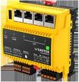
Type designation
Product name
Parameters
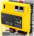
Connection of ecoLink I/O modules, COM modules, ASV actuators, ecoUnit room operating units, EnOcean wireless interface
I/O and COM extension modules 24 with modu601-LC (5 of which are COM modules)
Interfaces, communication
Interfaces 2 × RS-485, WAN, LAN, REST API, Bluetooth, USB, microSD RS-485, LAN, REST API, Bluetooth, USB, microSD
Ethernet/LAN 3 × RJ45 (switched) 2 × RJ45 (switched) Ethernet/WAN
SLC/RS-485 interfaces
Modbus/RS-485 interfaces
Protocols BACnet/IP, SLC, Modbus RTU, HTTP(S), NTP, SMTP, SMPP BACnet/IP, SLC, HTTP(S), NTP, SMTP, SMPP
BACnet profile
AMEV profile AS-B
Objects
Data points (BACnet objects)
data (Trend Log)
(Loop)
Sequences, scenes (Command)
I/O, 3200 total
EY6AS80: Modular BACnet automation station and web server, modu680-AS
Features
• Part of the SAUTER modulo 6 system family
• Modular automation station, expandable with I/O modules and communication modules
• Regulation, control, monitoring and optimisation of operational systems in HVAC engineering
• Locally expandable with up to 24 modules via the SAUTER Extension Bus
• Can be locally equipped with ecoLink I/O modules and ASV actuators via SLC interface
• RS-485 interface for field bus integration (Modbus/RTU/ASCII)
• Four RJ45 connections for two separate IP networks (OT/IT; Operational/Information Technology). Three connections switched for daisy chain
• BACnet/IP with device profile B-BC (EN ISO 16484‑5)
• AMEV AS-B profile
• With function expansion:
• BACnet/SC (encrypted communication)
• MQTT interface (MQTT Broker/Client)
• REST API interface
• Integrated web server for local commissioning, visualisation and operation
• User administration for identification, authentication and access control
• Encryption of communication with TLS
• Bluetooth interface for mobile commissioning and maintenance
• Programming/parameterisation via PC using CASE Suite (based on IEC 61131-3)
• Control libraries
• Time and calendar function
• Predictive control based on meteorological forecast data
• Data recording on removable media (microSD card)
• User administration and user identification (web server)
• Alive signal output pulsed
Technical data
Power supply
Parameters
Ambient conditions
1) Maximum load with 12 I/O modules
Power supply
Power consumption1)
Dissipated power
Peak inrush current
Connection
24 VDC ± 10%
≤ 2 W without load
≤ 24 W at maximum load
≤ 2 W without load
≤ 4 W at maximum load
≤ 20 A, ≤ 1 ms on the 24 V side
5-pin spring-type terminal, pluggable, 0.5…1.5 mm2 (rigid)
0.5…2.5 mm2, min. 8 mm wire stripped
Battery (buffer: RTC) CR2032, pluggable
Earth connector Spring contact against DIN rail and PE terminal
Operating temperature
0…45 °C
Storage and transport temperature−20…70°C


Function
BACnet
Dynamic objects
Services
Architecture
Ambient humidity 10…90% rh, no condensation
BACnet data point objects Up to 1600 I/O objects, 3200 in total
BACnet client links 600 (Peer-to-Peer)
Control 96 (Loop)
Active COV Subscription 4800
Structured view 128 (Structured View)
Sequences, scenes 16 (Command)
Time programmes 64 (Schedule)
Calendars 32 (Calendar)
Notification 32 (Notification Class) intrinsically or extrinsically with Event Enrollment
Historical data 1600 (Trend Log) up to 4 million entries
BBMD in BDT 32
FD in FDT 32
Embedded web server moduWeb Unity, MQTT Commissioning Tool
Web API (REST) moduWeb Unity (optional)
MQTT Broker/Client Optional
Notification (client) SMTP, SMPP
Time synchronisation NTP client, BACnet master or client, local or UTC
Processor
ARM Cortex A8, 32-bit, 1 GHz
RAM (memory) 512 MB (DDR3)
Flash 512 MB
Application data Via CASE Engine
Processes (BACnet programs)Supports separate processes with different cycle times and independent booting
Cycle time
Interfaces, communication
Ethernet network #1 (WAN)Communication protocols
Adjustable for each process, min. 50 ms (50, 100, 500, 1000)
HTTP(S), NTP, SMTP, SMPP, DHCP With function licence: MQTT/TCP(TLS), MQTT/WS(S)
Ethernet network 1 × RJ45 connector
10/100 BASE-T(X) 10/100 Mbit/s
Ethernet network #2 (LAN)Communication protocols BACnet/IP (DIX), HTTP(S), NTP, SMTP, SMPP, DHCP
With function licence: BACnet/SC, MQTT/TCP(TLS), MQTT/WS(S)
Ethernet network 3 × RJ45 connector
10/100 BASE-T(X) switched10/100 Mbit/s
Connection, I/O and COM modules Use2)
RS-485 A connection
Communication protocol
1 × integrated iSEB interface for up to 12 modules, expandable with modu601-LC for up to 24 modules in total
Modbus/RTU/ASCII
Modbus master according to V1.02
Bus physics 1 unit load (UL), galvanically isolated Bus speed 600...115 200 bit/s
Parity bit, stop bit, Rx/Tx bus timing
Connection Spring-type terminal, pluggable
Cable3)
2) Performance-dependent
3) Performance-dependent
0.2...1.5 mm2 rigid/flexible
3-/4-wire (D+/D−/COM reference), twisted, shielded, up to 1000 m
RS-485 B connection
Use
Integration of Modbus slaves in an RS-485 segment (line)
Participant Up to 31 RS-485 unit loads (UL)
Functions
120 Ω bus termination and pullup/pull-down
Communication protocol
Use
Up to 600 Modbus channels for BACnet I/O/V objects for up to 247 Modbus devices; FC01-06, 15, 16, 22; unicast and broadcast; access optimisation
Switchable via software (CASE Engine)
SLC master
ecoLink, ASV, ecoUnit, FCCP200
Participant Max. 8 ecoLink modules and 4 ecoUnit modules, max. 12 ASV units
Power supply 20…26 VDC, max. 1.5 W, protected against short circuits, can be switched on/off (CASE Sun)
Connection Spring-type terminal, pluggable
0.2...1.5 mm2 rigid/flexible
Line 4-wire, twisted, shielded
Cable length Max. 100 m (30 m) with ecoUnit or ASV, up to 500 m, bus termination necessary (120 Ω)
120 Ω bus termination and pullup/pull-down
Bluetooth
Switchable via software (CASE Sun)
Version BLE 4.0
Range < 10 m
Frequency band
2.402…2.480 GHz
Radiation 6 mW
USB Version 2.0, type A
Current limitation
400 to max. 500 mA
SD memory expansion Type microSD, suitable for industrial use
Construction
Fitting
Dimensions W × H × D
Standards, directives
CE/UKCA conformity5)
On metal DIN rail
35 × 7.5/15 as per EN 60715 DIN rail housing as per DIN 43880
92.6 (5 HP) × 100.9 × 59 mm
Weight 260 g
Type of protection
Protection class I
Connections: IP00
Front in DIN cut-out: IP30 (EN 60730-1)
Environment class 3K3 (IEC 60721)
Software class4) A (EN 60730-1, Appendix H)
Temperature controller classI to VIII = up to 5% as per 2009/125/EC, 2010/30/EU & 811/2013 (EU)
BACnet profile B-BC (ISO 16484-5)
AMEV profile AS-B
EMC-D 2014/30/EU (CE)EN 50491-5-1, EN 50491-5-2, EN 50491-5-3
EMC-2016 (UKCA) See EMC Directive LVD 2014/35/EU (CE) EN 60730-1, EN 60730-2-9, EN 62479
EESR-2016 (UKCA) See LVD
RED 2014/53/EU (CE) EN 300328 (V2.1.1)
RER-2017 (UKCA) EN 300328 (V2.1.1)
4) The product is not suitable for safety functions
5) Explanation of abbreviations in the “Further information” section of the product data sheet and in the appendix to SAUTER’s product catalogues
RoHS-D 2011/65/EU & 2015/863/EU (CE)
RoHS-2012 (UKCA)
EN IEC 63000
EN IEC 63000
Overview of types
Type Features
EY6AS80F021Modular BACnet automation station and web server
Accessories
Plug-in I/O modules
Type Description
EY6IO30F001modu630-IO 16 × DI/CI inputs I/O module
EY6IO70F001modu670-IO 8 × DI/CI/DO(OC), 8 × DI/CI I/O module
EY6IO31F001modu631-IO 8 × UI(DI/CI/AI), 8 × DI/CI I/O module
EY6IO71F001modu671-IO 8 × AO, 8 × DI/CI I/O module
EY6IO50F001modu650-IO 6 × relay (2 A) outputs I/O module
EY6IO72F001modu672-IO 4 × AO, 4 × DO(OC), 4 × UI (DI/CI/AI) I/O module
Power supply units
Type Description
EY-PS031F011Power supply, 110…240 VAC/24 VDC, 1.25 A, 30 W, DIN rail mounting
EY-PS031F021Power supply, 110…240 VAC/24 VDC, 2.5 A, 60 W, DIN rail mounting
EY-PS031F041Power supply, 110…240 VAC/24 VDC, 4 A, 100 W, DIN rail mounting
Connection modules
Type Description
EY6LC01F001Module for separate I/O module supply
EY6LC02F001Coupling kit for I/O modules in cabinet (P100017761 and P100017762)
EY6LC12F011IP coupler for I/O modules with web server, modu612‑LC
Spare parts
Type Description
0929360602AS bus cover with resistor, 5 pcs.
Function expansions
Type Description
Y6WS80F007Activation code for reporting for modu680-AS
Y6WS80F008Activation code for the REST API on modu680-AS
Y6WS80F009Data point extension activation code for moduWeb Unity on modu680-AS
Y6WS80F031Activation code for network option for modu680-AS
Y6WS80F100Activation code for touch-panel support
Y6FX02F001Activation code for MQTT client
Y6FX02F002Activation code for MQTT client and broker
Y6FX03F001Activation code for RADIUS Supplicant
Y6FX04F001Activation code for BACnet/SC node & hub Manuals
Document numberLanguageTitle
D100397589 de Systembeschreibung SAUTER modulo
D100408512 de EY-modulo 6 – Best Practice I
D100402674 en SAUTER modulo system description
D100410201 en EY-modulo 6 – Best Practice I
D100402676 fr Description du système SAUTER modulo
D100410203 fr EY-modulo 6 – Meilleures pratiques I
Features
• Part of the SAUTER modulo 6 system family
• Modular automation station, expandable with I/O modules and communication modules
• Regulation, control, monitoring and optimisation of operational systems in HVAC engineering
• Locally expandable with up to 24 modules via the SAUTER Extension Bus
• Can be locally equipped with ecoLink I/O modules and ASV actuators via SLC interface
• Two RJ45 connections switched for daisy chain
• BACnet/IP with device profile B-BC (EN ISO 16484‑5)
• AMEV AS-B profile
• With function expansion:
• BACnet/SC (encrypted communication)
• MQTT interface (MQTT Broker/Client)
• REST API interface
• Integrated web server for local commissioning, expandable with visualisation and operation
• User administration for identification, authentication and access control
• Encryption of communication with TLS
• Bluetooth interface for mobile commissioning and maintenance
• Programming/parameterisation via PC using CASE Suite (based on IEC 61131-3)
• Control libraries
• Time and calendar function
• Predictive control based on meteorological forecast data
• Data recording on removable media (microSD card)
• User administration and user identification (web server)
• Alive signal output pulsed
Technical data
Power supply
Parameters
Power supply
Power consumption1)
Dissipated power
Peak inrush current
Connection
Battery (buffer: RTC)
Earth connector
Ambient conditions
Function
1) Maximum load with 12 I/O modules
Operating temperature
24 VDC ± 10%
≤ 2 W without load
≤ 24 W at maximum load
≤ 2 W without load
≤ 4 W at maximum load
≤ 20 A, ≤ 1 ms on the 24 V side
5-pin spring-type terminal, pluggable,
0.5...1.5 mm²
0.5...2.5 mm², min. 8 mm wire stripped
CR2032, pluggable
Spring contact against DIN rail and PE terminal
0…45 °C
Storage and transport temperature−20…70°C
Ambient humidity 10…90% rh, no condensation
BACnet data point objects Up to 800 I/O objects, 1600 in total

Dynamic objects
Services
Architecture
BACnet client links
300 (Peer-to-Peer)
Control 48 (Loop)
Active COV Subscription 2400
Structured view 128 (Structured View)
Sequences, scenes 16 (Command)
Time programmes 64 (Schedule)
Calendars 32 (Calendar)
Notification 32 (Notification Class) intrinsically or extrinsically with Event Enrollment
Historical data 800 (Trend Log) up to 2 million entries
BBMD in BDT 32
FD in FDT 32
Embedded web server moduWeb Unity, MQTT Commissioning Tool
Web API (REST) moduWeb Unity (optional)
MQTT Broker/Client Optional Notification (client) SMTP, SMPP
Time synchronisation NTP client, BACnet master or client, local or UTC
Processor
ARM Cortex A8, 32-bit,1 GHz
RAM (memory) 512 MB (DDR3)
Flash 512 MB
Application data Via CASE Engine
Processes (BACnet programs)Supports separate processes with different cycle times and independent booting
Cycle time
Interfaces, communication
Ethernet network (LAN)
Communication protocols
Ethernet network
Adjustable via process, min. 50 ms (50, 100, 500, 1000)
BACnet/IP (DIX), BACnet/SC, HTTP(S), NTP, SMTP, SMPP, DHCP With function licence: MQTT/TCP(TLS), MQTT/WS(S)
2 × RJ45 connector 10/100 BASE-T(X) switched10/100 Mbit/s
Connection, I/O and COM modules Use2)
RS-485 B connection
Communication protocol
Bluetooth
USB
2) Performance-dependent
1 × integrated iSEB interface for up to 12 modules, expandable with modu601-LC for up to 24 modules in total
SLC master
Use ecoLink, ASV, ecoUnit, FCCP 200 Participant Max. 8 ecoLink modules and 4 ecoUnit modules, max. 12 ASV units
Power supply 20…26 VDC, max. 1.5 W, protected against short circuits, can be switched on/off (CASE Sun)
Connection Spring-type terminal, pluggable 0.2...1.5 mm² rigid/flexible
Line 4-wire, twisted, shielded
Cable length Max. 100 m (30 m) with ecoUnit or ASV; up to 500 m, bus termination necessary (120 Ω)
120 Ω bus termination and pullup/pull-down
Version
Switchable via software (CASE Sun)
BLE 4.0
Range < 10 m
Frequency band 2.402…2.480 GHz
Radiation 6 mW
Version 2.0, type A
Current limitation
400 to max. 500 mA
SD memory expansion
Construction
Standards, directives
Type
Fitting
CE/UKCA conformity4)
microSD, suitable for industrial use
On metallic DIN rail 35 × 7.5/15 as per EN 60715
DIN rail housing as per DIN 43880
Dimensions W × H × D 92.6 (5 HP) x 100.9 x 59 mm
Weight 240 g
Type of protection
Protection class I
Connections: IP00
Front in DIN cut-out: IP30 (EN 60730-1)
Environment class 3K3 (IEC 60721)
Software class3) A (EN 60730-1, Appendix H)
Temperature controller classI to VIII = up to 5% as per 2009/125/EC, 2010/30/EU & 811/2013 (EU)
BACnet profile B-BC (ISO 16484-5)
AMEV profile AS-B
EMC-D 2014/30/EU (CE)EN 50491-5-1, EN 50491-5-2, EN 50491-5-3
EMC-2016 (UKCA)
LVD 2014/35/EU (CE)
See EMC Directive
EN 60730-1, EN 60730-2-9, EN 62479
EESR-2016 (UKCA) See LVD
RED 2014/53/EU (CE)
RER-2017 (UKCA)
RoHS-D 2011/65/EU & 2015/863/EU (CE)
RoHS-2012 (UKCA)
EN 300328 (V2.1.1)
EN 300328 (V2.1.1)
EN IEC 63000
EN IEC 63000
Overview of types
Type Description
EY6AS60F011Modular BACnet automation station and web server
Accessories
Plug-in I/O modules
Type Description
EY6IO30F001modu630-IO 16 × DI/CI inputs I/O module
EY6IO31F001modu631-IO 8 × UI(DI/CI/AI), 8 × DI/CI I/O module
EY6IO50F001modu650-IO 6 × relay (2 A) outputs I/O module
EY6IO70F001modu670-IO 8 × DI/CI/DO(OC), 8 × DI/CI I/O module
EY6IO71F001modu671-IO 8 × AO, 8 × DI/CI I/O module
EY6IO72F001modu672-IO 4 × AO, 4 × DO(OC), 4 × UI (DI/CI/AI) I/O module
Power supply units
Type Description
EY-PS031F011Power supply, 110…240 VAC/24 VDC, 1.25 A, 30 W, DIN rail mounting
EY-PS031F021Power supply, 110…240 VAC/24 VDC, 2.5 A, 60 W, DIN rail mounting
EY-PS031F041Power supply, 110…240 VAC/24 VDC, 4 A, 100 W, DIN rail mounting
3) The product is not suitable for safety functions
4) Explanation of abbreviations in the “Further information” section of the product data sheet and in the appendix to SAUTER’s product catalogues
Connection modules
Type Description
EY6LC01F001Module for separate I/O module supply
EY6LC02F001Coupling kit for I/O modules in cabinet (P100017761 and P100017762)
EY6LC12F011IP coupler for I/O modules with web server, modu612‑LC
Spare parts
Type Description
0929360602AS bus cover with resistor, 5 pcs.
Function expansions
Type Description
Y6WS60F007Activation code for reporting for modu660-AS (requires Y6WS60F021)
Y6WS60F008Activation code for the REST API on modu660-AS (requires Y6WS60F021)
Y6WS60F009Data point extension activation code for moduWeb Unity on modu660 AS (requires Y6WS60F021)
Y6WS60F021 Activation code for visualisation on modu660 AS
Y6WS60F100Activation code for touch-panel support
Y6FX02F001Activation code for MQTT client
Y6FX02F002Activation code for MQTT client and broker
Y6FX03F001Activation code for RADIUS Supplicant
Y6FX04F001Activation code for BACnet/SC node & hub
Manuals
Document numberLanguageTitle
D100397589 de Systembeschreibung SAUTER modulo
D100408512 de EY-modulo 6 – Best Practice I
D100402674 en SAUTER modulo system description
D100410201 en EY-modulo 6 – Best Practice I
D100402676 fr Description du système SAUTER modulo
D100410203 fr EY-modulo 6 – Meilleures pratiques I
The SAUTER modulo 6 connection modules offer more flexibility in the cabinet installation (modu602 LC) and more freedom for a decentralised topology (modu612 LC). The modu601 LC ensures the functionality of the I/O modules if the operation of the automation station is interrupted.
Overview of connection modules

(switch) I/O and COM extension modules
24 (of which 5 are COM modules)
Cloud Connector
Features
• Part of the SAUTER modulo 6 system family
• Enables separate supply between automation station and I/O modules
• Power supply of I/O modules and connected LOI units (Local Override and Indication Device)
• Allows extension to up to 24 I/O modules
• Enables simple wiring tests of the I/O modules without the station, together with modu600-LO on the I/O modules
Technical data
Power supply
Parameters
Ambient conditions
Interfaces, communication
Power supply 24 V= ± 10%
Dissipated power < 0.5 W
Power consumption < 19 W at max. load
Peak inrush current1) ≤ 2 A, ≤ 10 ms
Connection 3-pin spring-type terminal, pluggable, 0.5...1.5 mm2 (rigid)
0.5...2.5 mm2, min. 8 mm wire stripped
Operating temperature 0...45 °C
Storage and transport temperature−25...70 °C
Ambient humidity 10...90% rh, no condensation
Connection, I/O bus 6-pin spring contacts left and 7-pin right
Earth connector
Construction
Standards, directives
Fitting
Spring contact against DIN rail and PE feed connection
On metal DIN rail 35 × 7.5/15 as per EN 60715
DIN rail housing as per DIN 43880
Dimensions W × H × D 56 × 97 × 59 mm
Weight 98 g
Type of protection (as per EN 60730)Connections and terminals: IP00 Front in DIN cut-out: IP30
Protection class I
Environment class 3K3 (IEC 60721)
CE conformity according toEMC Directive 2014/30/EUEN 61000-6-1, EN 61000-6-2, EN 61000-6-3, EN 61000-6-4, EN 50491-5-1, EN 50491-5-2, EN 50491-5-3
Overview of types
Type Description
EY6LC01F001Module for separate I/O module supply

1) Measured value with EY PS021F021 power supply unit
Manuals
Document numberLanguageTitle
D100397589 de Systembeschreibung SAUTER modulo
D100408512 de EY-modulo 6 – Best Practice I
D100402674 en SAUTER modulo system description
D100410201 en EY-modulo 6 – Best Practice I
D100402676 fr Description du système SAUTER modulo
D100410203 fr EY-modulo 6 – Meilleures pratiques I
EY6LC02: Coupling kit for I/O modules in cabinet, modu602LC
Features
• Part of the SAUTER modulo 6 system family
• Arrangement of I/O modules in up to three rows for space-optimised cabinet installation
• Minimum space requirement of the transmitter and receiver modules (1.5 HP)
• Up to two modu602-LC per station
Technical data
Power supply
Parameters
Ambient conditions
Interfaces, communication
Power supply
Construction
Standards, directives

From AS or LC via I/O bus
Dissipated power < 0.3 W incl. 3 m cable
Max. number per station 2
Max. cable length per station3 m
Operating temperature 0...45 °C
Storage and transport temperature−25...70 °C
Ambient humidity 10...90% rh, no condensation
Connection
Cable type
Connection, I/O bus
Earth connector
Fitting
RJ45 connector
RJ45 type S/FTP, not crossed, at least AWG 24
P100017761: 7-pin spring contacts, only left
P100017762: 7-pin spring contacts, only right
Spring contact against DIN rail
On metal DIN rail 35 × 7.5/15 as per EN 60715
DIN rail housing as per DIN 43880
Dimensions W × H × D 27 × 97 × 59 mm
Weight1) 95 g
Type of protection (as per EN 60730)Connections and terminals: IP00
Front in DIN cut-out: IP30
Protection class I
Environment class 3K3 (IEC 60721)
CE conformity according toEMC Directive 2014/30/EUEN 61000-6-1, EN 61000-6-2, EN 61000-6-3, EN 61000-6-4, EN 50491-5-1, EN 50491-5-2, EN 50491-5-3
Overview of types
Type Description
EY6LC02F001Coupling kit for I/O modules in cabinet (P100017761 and P100017762)
Manuals
Document numberLanguageTitle
D100397589 de Systembeschreibung SAUTER modulo D100408512 de EY-modulo 6 – Best Practice I
1) Total weight
Document numberLanguageTitle
D100402674 en SAUTER modulo system description
D100410201 en EY-modulo 6 – Best Practice I
D100402676 fr Description du système SAUTER modulo
D100410203 fr EY-modulo 6 – Meilleures pratiques I
EY6LC12: IP coupler for I/O modules, with web server, modu612 LC
Features
• Part of the SAUTER modulo 6 system family
• Enables decentralised installation and connection of the modulo 6 COM and IO modules with the automation station via IP network
• Locally expandable with up to 10 modules
• Two RJ45 connections switched for daisy chain
• Integrated web server for local commissioning
• Bluetooth interface for mobile commissioning and maintenance
• User administration and user identification (web server)
Technical data
Power supply
Parameters
Ambient conditions
Architecture
Power supply
Power consumption1)
Dissipated power
Peak inrush current2)
Connection
24 VDC ± 10%
≤ 2 W without load
≤ 24 W at maximum load
≤ 2 W without load
≤ 4 W at maximum load
≤ 20 A, ≤ 1 ms on the 24 V side
3-pin spring-type terminal, pluggable, 0.5...1.5 mm² (rigid)
0.5...2.5 mm², min. 8 mm wire stripped
Battery (buffer: RTC) CR2032, pluggable
Earth connector Spring contact against DIN rail and PE terminal
Operating temperature
0…45 °C
Storage and transport temperature−20…70 °C
Ambient humidity 10…90% rh, no condensation
Processor
Interfaces, communication
Ethernet network
Construction
ARM Cortex A8, 32-bit, 600 MHz
Embedded web server moduWeb Unity
Application data From the automation station
Ethernet network
2 × RJ45 connector, switched 10/100 BASE-T(X) switched10/100 Mbit/s
Dimensions W × H × D
Fitting
Standards, directives
Type of protection

92.6 (5 HP) × 97 × 58.3 mm
On metal DIN rail
35 × 7.5/15 as per EN 60715. Rail housing as per DIN 43880
Connections: IP00
Front in DIN cut-out: IP30 (EN 60730-1)
Protection class I (EN 60730-1)
Environment class 3K3 (IEC 60721)
1) Maximum load with 12 I/O modules
2) Measured value with EY-PS021F021 power supply unit
Software class A (EN 60730-1, Appendix H)
Energy class I to VIII = up to 5% as per EU 811/2013, 2010/30/EU, 2009/125/EC
CE/UKCA conformity3) EMC-D 2014/30/EU (CE)EN 50491-5-1, EN 50491-5-2, EN 50491-5-3
EMC-2016 (UKCA)
LVD 2014/35/EU (CE)
EESR-2016 (UKCA)
RED 2014/53/EU (CE)
RER-2017 (UKCA)
RoHS-D 2011/65/EU & 2015/863/EU (CE)
RoHS-2012 (UKCA)
See EMC Directive
EN 60730-1, EN 60730-2-9, EN 62479
EN 60730-1, EN 60730-2-9, EN 62479
EN 300328 (V2.1.1)
EN 300328 (V2.1.1)
EN IEC 63000
EN IEC 63000
Overview of types
Type Description
EY6LC12F011IP coupler for I/O modules, with web server
Accessories
Plug-in I/O modules
Type Description
EY6IO30F001modu630-IO 16 × DI/CI inputs I/O module
EY6IO31F001modu631-IO 8 × UI(DI/CI/AI), 8 × DI/CI I/O module
EY6IO50F001modu650-IO 6 × relay (2 A) outputs I/O module
EY6IO70F001modu670-IO 8 × DI/CI/DO(OC), 8 × DI/CI I/O module
EY6IO71F001modu671-IO 8 × AO, 8 × DI/CI I/O module
EY6IO72F001modu672-IO 4 × AO, 4 × DO(OC), 4 × UI (DI/CI/AI) I/O module
Plug-in communication modules (COM)
Type Description
EY6CM20F011Modbus/RTU (RS-485) communication module
EY6CM30F031modu630-CM M-Bus communication module
Connection modules
Type Description
EY6LC01F001Module for separate I/O module supply
EY6LC02F001Coupling kit for I/O modules in cabinet (P100017761 and P100017762)
3) Explanation of abbreviations in the “Further information” section of the product data sheet and in the appendix to SAUTER’s product catalogues
SAUTER I/O modules are compatible with the modulo 6 series and are used to capture digital and analogue signals in HVAC installations. They control devices such as contactors, relays and valve actuators.


Features
• Part of the SAUTER modulo 6 system family
• Plug-in element for extending the modu660‑AS and modu680‑AS automation stations and the modu612‑LC IP coupler
• Receiving digital inputs (alarm, status or pulse counter) in operational systems, e.g. in HVAC engineering
• 16 digital inputs
• Power supply from modu6**-AS automation station, modu612‑LC IP coupler or modu601‑LC supply module
• Can be equipped locally with a modu600‑LO operating and indicating unit
Technical data
Power supply
Ambient conditions
Inputs/outputs
Digital inputs (DI/CI)
Interfaces, communication
Power supply
Construction
Standards, directives
CE/UKCA conformity4)
From AS or LC via I/O bus
Dissipated power1) ≤ 0.8 W
Operating temperature 0…45 °C
Storage and transport temperature−20…70 °C
Ambient humidity 10…90% rh, no condensation
Number of inputs 16
Power supply for DI
Internal, ~13 VDC
Pulse counter2) ≤ 50 Hz
Connection, LOI 4-pin
Connection, I/O bus 7-pin, spring contact
Connection terminals 4 x 8-pin spring-loaded plug-in connectors
Earth connector
Fitting
Spring contact against DIN rail
On metal DIN rail
35 x 7.5/15 as per EN 60715. DIN rail housing as per DIN 43880
Dimensions W × H × D 56 (3 HP) × 100 × 59 mm
Weight 130 g
Type of protection
Connections and terminals:IP00
Front in DIN cut-out:IP30<br(EN 60730-1)
Protection class I (EN 60730-1)
Software class3) A (EN 60730-1, Appendix H)
Environment class 3K3 (IEC 60721)
EMC-D 2014/30/EU (CE)EN 50491-5-1, EN 50491-5-2, EN 50491-5-3
EMC-2016 (UKCA) See EMC Directive
RoHS-D 2011/65/EU & 2015/863/EU (CE)
RoHS-2012 (UKCA)
EN IEC 63000
EN IEC 63000
1) Measured value without accessories
2) 50 Hz only with PC module, otherwise 5 Hz
3) The product is not suitable for safety functions
4) Explanation of abbreviations in the “Further information” section of the product data sheet and in the appendix to SAUTER’s product catalogues

Overview of types
Type Features
EY6IO30F00116 x DI/CI inputs I/O module
Accessories
Type Description
EY6LO00F001Local operating and indicating unit for I/O modules Manuals
Document numberLanguageTitle
D100397589 de SAUTER modulo system description
D100408512 de EY-modulo 6 – Best Practice I
D100402674 en SAUTER modulo system description
D100410201 en EY-modulo 6 – Best Practice I
D100402676 fr Description du système SAUTER modulo
D100410203 fr EY-modulo 6 – Meilleures pratiques I
8 × UI (DI/CI/AI), 8 × DI/CI I/O module, modu631IO
Features
• Part of the SAUTER modulo 6 system family
• Plug-in element for extending the modu660‑AS and modu680‑AS automation stations and the modu612‑LC IP coupler
• Receiving digital inputs (alarm, status or pulse counter) and analogue inputs (Ni/Pt1000, R, U) in operational systems, e.g. in HVAC
• Eight digital inputs and eight universal inputs
• Power supply from modu6**-AS automation station, modu612‑LC IP coupler or modu601‑LC supply module
• Can be equipped locally with a modu600‑LO operating and indicating unit
Technical data
Power supply
Ambient conditions
Inputs/outputs
Digital inputs (DI/CI)
Universal inputs (UI)
Interfaces, communication
Power supply
From AS or LC via I/O bus
Dissipated power1) ≤ 0.8 W
Operating temperature
0…45 °C
Storage and transport temperature−20…70 °C
Ambient humidity 10…90% rh, no condensation
Number of inputs 8
Power supply for DI
Internal, ~13 VDC
Pulse counter ≤ 50 Hz
Number of inputs 8
Analogue
Construction
Standards, directives
U: 0(2)…10 V Ni1000, Pt1000 R: 200…2500 Ω
Digital2) DI/CI: ≤ 50 Hz
Connection, LOI 4-pin
Connection, I/O bus 7-pin, spring contact
Connection terminals 4 x 8-pin spring-loaded plug-in connectors
Earth connector Spring contact against DIN rail
Fitting
On metal DIN rail
35 x 7.5/15 as per EN 60715. DIN rail housing as per DIN 43880
Dimensions W × H × D 56 (3 HP) × 100 × 59 mm
Weight 131 g
Type of protection
Connections and terminals:IP00 Front in DIN cut-out:IP30<br(EN 60730-1)
Protection class I (EN 60730-1)
Software class3) A (EN 60730-1, Appendix H)
Environment class 3K3 (IEC 60721)
1) Measured value without accessories
2) DI: 50 Hz only with PC module, otherwise 5 Hz
3) The product is not suitable for safety functions

CE/UKCA conformity4)
EMC-D 2014/30/EU (CE)EN 50491-5-1, EN 50491-5-2, EN 50491-5-3
EMC-2016 (UKCA) See EMC Directive
RoHS-D 2011/65/EU & 2015/863/EU (CE) EN IEC 63000
RoHS-2012 (UKCA) EN IEC 63000
Overview of types
Type Features
EY6IO31F0018 x UI(DI/CI/AI) and 8 x DI/CI I/O module
Accessories
Type Description
EY6LO00F001Local operating and indicating unit for I/O modules Manuals
Document numberLanguageTitle
D100397589 de Systembeschreibung SAUTER modulo
D100408512 de EY-modulo 6 – Best Practice I
D100402674 en SAUTER modulo system description
D100410201 en EY-modulo 6 – Best Practice I
D100402676 fr Description du système SAUTER modulo
D100410203 fr EY-modulo 6 – Meilleures pratiques I
4) Explanation of abbreviations in the “Further information” section of the product data sheet and in the appendix to SAUTER’s product catalogues
Features
• Part of the SAUTER modulo 6 system family
• Plug-in element for extending the modu660‑AS and modu680‑AS automation stations and the modu612‑LC IP coupler
• Activation of displays in operational systems, such as HVAC engineering
• Activation of actuators such as contactors or valve actuators, in operational systems
• Six digital outputs (relay)
• Power supply from modu6**-AS automation station, modu612‑LC IP coupler or modu601‑LC supply module
• Can be equipped locally with a modu600‑LO operating and indicating unit
Technical data
Power supply
Ambient conditions
Inputs/outputs
Digital outputs (DO)
Interfaces, communication
Power supply
From AS or LC via I/O bus
Dissipated power1) ≤ 1,3 W
Operating temperature
0…45 °C
Storage and transport temperature−20…70 °C
Ambient humidity 10…90% rh, no condensation
Number of outputs
Type of outputs
Load
6
Relay (0-I), normally-open contact, galvanically isolated
24 VDC, 24...250 VAC
Resistive load: 2 A
Inductive load: ≤ 1 A, cos φ ≥ 0.8
Start-up current: ≤ 5 A
Switching frequency, mechanical300,000 cycles for 2 A
Connection, LOI 4-pin
Connection, I/O bus 7-pin, spring contact
Connection terminals 6 x 2-pin spring-loaded plug-in connectors
Earth connector
Construction
Standards, directives
1) Measured value without accessories
Fitting
Spring contact against DIN rail
On metallic DIN rail
35 x 7.5/15 as per EN 60715. DIN rail housing as per DIN 43880
Dimensions W × H × D 56 (3 HP) × 98 × 59 mm
Weight 124 g
Type of protection
Connections and terminals:IP00
Front in DIN cut-out:IP30<br(EN 60730-1)
Protection class I (EN 60730-1)
Software class2) A (EN 60730-1, Appendix H)
Environment class 3K3 (IEC 60721)
2) The product is not suitable for safety functions

CE/UKCA conformity3)
EMC-D 2014/30/EU (CE)EN 50491-5-1, EN 50491-5-2, EN 50491-5-3
EMC-2016 (UKCA) See EMC Directive
RoHS-D 2011/65/EU & 2015/863/EU (CE) EN IEC 63000
RoHS-2012 (UKCA) EN IEC 63000
Overview of types
Type Features
EY6IO50F0016 x relay (2 A) outputs I/O module
Accessories
Type Description
EY6LO00F001Local operating and indicating unit for I/O modules Manuals
Document numberLanguageTitle
D100397589 de Systembeschreibung SAUTER modulo
D100408512 de EY-modulo 6 – Best Practice I
D100402674 en SAUTER modulo system description
D100410201 en EY-modulo 6 – Best Practice I
D100402676 fr Description du système SAUTER modulo
D100410203 fr EY-modulo 6 – Meilleures pratiques I
3) Explanation of abbreviations in the “Further information” section of the product data sheet and in the appendix to SAUTER’s product catalogues
EY6IO70: 8 × DI/CI/DO (OC) and 8 × DI/CI I/O module, modu670 IO
Features
• Part of the SAUTER modulo 6 system family
• Plug-in element for extending the modu660‑AS and modu680‑AS automation stations and the modu612‑LC IP coupler
• Activation of actuators such as relays and displays of operational systems, e.g. in HVAC engineering
• Activation of displays in operational systems
• Receiving digital inputs (alarm, status or pulse counter) in operational systems
• Eight digital inputs and eight digital inputs/outputs
• Power supply from modu6**-AS automation station, modu612‑LC IP coupler or modu601‑LC supply module
• Can be equipped locally with a modu600‑LO operating and indicating unit
Technical data
Power supply
Ambient conditions
Inputs/outputs
Digital inputs (DI/CI)
Power supply
From AS or LC via I/O bus
Dissipated power1) ≤ 0,8 W
Operating temperature
0…45 °C
Storage and transport temperature−20…70 °C
Ambient humidity 10…90% rh, no condensation
Number of inputs 8
Pulse counter2)
≤ 50 Hz
Digital inputs/outputs (DIO)Number of inputs/outputs 8
Type of inputs/outputs
Open collector, normally-open contacts (0-I), outputs switched with respect to ground (any arrangement)
Power supply for DO External, positive ≤ 28 VDC Load 0...100 mA (max. 2 V voltage drop)
Power supply for DI Internal, ~13 VDC
Pulse counter3) ≤ 50 Hz
Interfaces, communication
Construction
1) Measured value without accessories
Connection, LOI 4-pin
Connection, I/O bus 7-pin, spring contact
Connection terminals 4 x 8-pin spring-loaded plug-in connectors
Earth connector
Fitting
Spring contact against DIN rail
On metallic DIN rail 35 x 7.5/15 as per EN 60715
DIN rail housing as per DIN 43880
Dimensions W × H × D 56 (3 HP) × 100 × 59 mm
Weight 131 g
2) 50 Hz only with PC module, otherwise 5 Hz
3) 50 Hz only with PC module, otherwise 5 Hz

Standards, directives
Type of protection
Protection class
CE/UKCA conformity5)
Connections and terminals:IP00 Front in DIN cut-out:IP30<br(EN 60730-1)
I (EN 60730-1)
Software class4) A (EN 60730-1, Appendix H)
Environment class 3K3 (IEC 60721)
EMC-D 2014/30/EU (CE)EN 50491-5-1, EN 50491-5-2, EN 50491-5-3
EMC-2016 (UKCA) See EMC Directive
RoHS-D 2011/65/EU & 2015/863/EU (CE) EN IEC 63000
RoHS-2012 (UKCA) EN IEC 63000
Overview of types
Type Features
EY6IO70F0018 x DI/CI/DO(OC) and 8 x DI/CI I/O module
Accessories
Type Description
EY6LO00F001Local operating and indicating unit for I/O modules Manuals
Document numberLanguageTitle
D100397589 de Systembeschreibung SAUTER modulo
D100408512 de EY-modulo 6 – Best Practice I D100402674 en SAUTER modulo system description D100410201 en EY-modulo 6 – Best Practice I
D100402676 fr Description du système SAUTER modulo D100410203 fr EY-modulo 6 – Meilleures pratiques I
4) The product is not suitable for safety functions
5) Explanation of abbreviations in the “Further information” section of the product data sheet and in the appendix to SAUTER’s product catalogues
Features
• Part of the SAUTER modulo 6 system family
• Plug-in element for extending the modu660‑AS and modu680‑AS automation stations and the modu612‑LC IP coupler
• Activation with a standard signal (0(2)...10 V) in operational systems, such as HVAC engineering
• Receiving digital inputs (alarm, status or pulse counter) in operational systems
• Eight digital inputs and eight analogue outputs
• Power supply from modu6**-AS automation station, modu612‑LC IP coupler or modu601‑LC supply module
• Can be equipped locally with a modu600‑LO operating and indicating unit
Technical data
Power supply
Power supply
Ambient conditions
Inputs/outputs
Digital inputs (DI/CI)
Analogue outputs (AO)
Interfaces, communication
Construction
Standards, directives
From AS or LC via I/O bus
Power consumption ≤ 1 W
Dissipated power1) ≤ 0,8 W
Operating temperature
0…45 °C
Storage and transport temperature−20…70 °C
Ambient humidity 10…90% rh, no condensation
Number of inputs 8
Power supply for DI Internal, ~13 VDC
Pulse counter2) ≤ 50 Hz
Number of outputs 8
Analogue 0(2)…10 V
Load ≤ 2 mA
Connection, LOI 4-pin
Connection, I/O bus 7-pin, spring contact
Connection terminals 4 x 8-pin spring-loaded plug-in connectors
Earth connector Spring contact against DIN rail
Fitting
On metal DIN rail 35 x 7.5/15 as per EN 60715. DIN rail housing as per DIN 43880
Dimensions W × H × D 56 (3 HP) × 100 × 59 mm
Weight 130 g
Type of protection
Connections and terminals:IP00
Front in DIN cut-out:IP30<br(EN 60730-1)
Protection class I (EN 60730-1)
Software class3) A (EN 60730-1, Appendix H)
Environment class 3K3 (IEC 60721)
1) Measured values without accessories
2) 50 Hz only with PC module, otherwise 5 Hz
3) The product is not suitable for safety functions

CE/UKCA conformity4)
EMC-D 2014/30/EU (CE)EN 50491-5-1, EN 50491-5-2, EN 50491-5-3
EMC-2016 (UKCA) See EMC Directive
RoHS-D 2011/65/EU & 2015/863/EU (CE) EN IEC 63000
RoHS-2012 (UKCA) EN IEC 63000
Overview of types
Type Features
EY6IO71F0018 x AO and 8 x DI/CI I/O module
Accessories
Type Description
EY6LO00F001Local operating and indicating unit for I/O modules Manuals
Document numberLanguageTitle
D100397589 de Systembeschreibung SAUTER modulo
D100408512 de EY-modulo 6 – Best Practice I
D100402674 en SAUTER modulo system description
D100410201 en EY-modulo 6 – Best Practice I
D100402676 fr Description du système SAUTER modulo
D100410203 fr EY-modulo 6 – Meilleures pratiques I
4) Explanation of abbreviations in the “Further information” section of the product data sheet and in the appendix to SAUTER’s product catalogues
EY6IO72: 4 × AO, 4 × DO(OC), 4 × UI (DI/CI/AI) I/O module, modu672 IO
Features
• Part of the SAUTER modulo 6 system family
• Plug-in element for extending the modu660‑AS and modu680‑AS automation stations and the modu612‑LC IP coupler
• Activation with a standard signal (0(2)…10 V, 0(4)…20 mA) in operational systems, such as HVAC engineering
• Receiving digital inputs (alarm/status or pulse counter) and analogue inputs (Ni/Pt1000, U, I, R, pot.) in operational systems
• Four universal inputs, four analogue outputs and four digital outputs
• Power supply from modu6**-AS automation station, modu612‑LC IP coupler or modu601‑LC supply module
• Can be equipped locally with a modu600‑LO operating and indicating unit
Technical data
Power supply
Power supply
Ambient conditions
Inputs/outputs
Universal inputs (UI)
Analogue outputs (AO)
From AS or LC via I/O bus
Power consumption ≤ 3 W
Dissipated power1) ≤ 3 W
Operating temperature 0…45 °C
Storage and transport temperature−20…70 °C
Ambient humidity 10…90% rh, no condensation
Number of inputs
Analogue
4
U: 0(2)…10 V
I: 0(4)…20 mA
R: 200…2500 Ω Ni1000, Pt1000 Potentiometer
Reference voltage 3 V (potentiometer)
Digital2) DI/CI (≤ 50 Hz)
Number of outputs
Analogue
Voltage output (U)
Digital outputs (DO)
4
U: 0(2)…10 V
I: 0(4)…20 mA
Load > 5 kΩ
Current output (I) Load < 500 Ω
Number of outputs 4
Type of outputs
Power supply for DO
Load
Interfaces, communication
Open collector, NO contact (0-I), outputs switching to ground
External, positive ≤ 28 VDC
Typ. 100 mA, max. 250 mA
Voltage drop ≤ 1.5 V
Connection, LOI 4-pin
Connection, I/O bus 7-pin, spring contact
Connection terminals 4 × 8-pin spring-loaded plug-in connectors
Earth connector
Spring contact against DIN rail
1) Measured value without accessories
2) 50 Hz only with PC module, otherwise 5 Hz

Construction
Standards, directives
CE/UKCA conformity4)
Fitting On metal DIN rail 35 × 7.5/15 as per EN 60715. DIN rail housing as per DIN 43880
Dimensions W × H × D 56 (3 HP) × 100 × 59 mm
Weight 137 g
Type of protection
Connections and terminals: IP00 Front in DIN cut-out:IP30 (EN 60730-1)
Protection class I (EN 60730-1)
Software class3) A (EN 60730-1, Appendix H)
Environment class 3K3 (IEC 60721)
EMC-D 2014/30/EU (CE)EN 50491-5-1, EN 50491-5-2, EN 50491-5-3
EMC-2016 (UKCA) See EMC Directive
RoHS-D 2011/65/EU & 2015/863/EU (CE) EN IEC 63000
RoHS-2012 (UKCA) EN IEC 63000
Overview of types
Type Features
EY6IO72F0014 × AO, 4 × DO(OC), 4 × UI (DI/CI/AI) I/O module
Accessories
Type Description
EY6LO00F001Local operating and indicating unit for I/O modules
Manuals
Document numberLanguageTitle
D100397589 de Systembeschreibung SAUTER modulo D100408512 de EY-modulo 6 – Best Practice I D100402674 en SAUTER modulo system description D100410201 en EY-modulo 6 – Best Practice I D100402676 fr Description du système SAUTER modulo D100410203 fr EY-modulo 6 – Meilleures pratiques I
3) The product is not suitable for safety functions
4) Explanation of abbreviations in the “Further information” section of the product data sheet and in the appendix to SAUTER’s product catalogues
The SAUTER modulo 6 operating unit allows you to display the current status of the inputs and to directly override the outputs of the I/O modules – local priority operation as per EN ISO 16484 2.
Type designation EY6LO00F001
Product name modu600-LO
Power supply From I/O module
Device Operating device with 4 push-buttons
Function Visualisation, operation
Display
Display of analogue, digital and multi-state signals
Use Universally for I/O modules
Further information Page 388
EY6LO00: Operating and indicating unit for I/O modules, modu600-LO
Features
• Part of the SAUTER modulo 6 system family
• Pluggable element for direct operation and visualisation of displays for the modu6** I/O modules
• Automatic detection of the current I/O module configuration
• Display of values and statuses of the inputs and outputs on an LCD colour display
• Detailed display of the individual inputs and outputs including labelling, type, status and graphics
• Simple 4-button operation
• LED indicator of I/O module modu6**-IO
• Local priority operation
• Ready for use without parameterising
Technical data
Power supply
Ambient conditions
Indicators, display, operation
Power supply From I/O module modu6**-IO
Current consumption ≤ 12.5 mA
Dissipated power ≤ 0,3 W
Operating temperature 0…45 °C
Storage and transport temperature−25…60 °C
Ambient humidity 10…90% rh, no condensation
Resolution
Interfaces, communication
Standards, directives
CE/UKCA conformity1)
240 × 240 pixels, colour LCD
Operation Four buttons: Back/reject, Reverse/reduce, Forward/increase, Confirm
Connection 4-pin, spring contacts
Protocol Proprietary
Type of protection
Connections: IP00 front, plugged in: IP30 (EN 60730-1)
Protection class III (EN 60730-1)
Environment class 3K3 (IEC 60721)
EMC-D 2014/30/EU (CE)EN 50491-5-1, EN 50491-5-2, EN 50491-5-3
EMC-2016 (UKCA) See EMC Directive
RoHS-D 2011/65/EU & 2015/863/EU (CE)
RoHS-2012 (UKCA)
Overview of types
Type Features
EY6LO00F001modu600-LO, operating and indicating unit for I/O modules
EN IEC 63000
EN IEC 63000

1) Explanation of abbreviations in the “Further information” section of the product data sheet and in the appendix to SAUTER’s product catalogues
Manuals
Document numberLanguageTitle
D100386646 de modu600‑LO Bedienungsanleitung
D100397589 de Systembeschreibung SAUTER modulo
D100408512 de EY-modulo 6 – Best Practice I
D100408262 en modu600-LO Operating instructions
D100402674 en SAUTER modulo system description
D100410201 en EY-modulo 6 – Best Practice I
D100408261 fr modu600-LO Notice d'emploi
D100402676 fr Description du système SAUTER modulo
D100410203 fr EY-modulo 6 – Meilleures pratiques I
SAUTER communication modules enable third-party systems to be integrated on the automation level. Field-bus protocols, based on EIA-232 or EIA-485, such as Modbus/RTU and M-Bus, can be integrated directly on the automation station. The data is mapped in BACnet objects and is visible on the BACnet/IP network.
of communication modules
EY6CM20: Modbus/RTU (RS 485) communication module, modu620 CM
Features
• Part of the SAUTER modulo 6 system family
• Plug-in element for extending the modu680‑AS and modu660‑AS automation stations or modu612‑LC link coupler
• Up to five COM modules per automation station
• Connection to non-SAUTER systems (PLC, chillers, meters etc.)
• RS-485, half duplex, electrically isolated interface for Modbus/RTU, Modbus/ASCII
• Electrical isolation
• Configurable RS-485 network resistors (software)
• Baud rate 600...115 200 bit/s
• Modbus master with up to four Modbus communication profiles
• Integrated tunnelling function for commissioning and monitoring with serial Modbus master tools
Technical data
Power supply
Ambient conditions
Interfaces, communication
RS-485 (Modbus)
Construction
Power supply
Power consumption
Dissipated power
Operating temperature
From AS or LC via I/O bus
30 mA (AS-LC)
≤ 0.7 W
0…45 °C
Storage and transport temperature−25…70 °C
Ambient humidity
10…90% rh, no condensation
Communication protocol Modbus/RTU and Modbus/ASCII master as per V1.02, 2-wire (2W)
Bus physics
Bus speed
Connection
Cable
Use
Participant
Functions
120 Ω bus termination and pullup/pull-down
Fitting
1 unit load (unit load (UL)); electrically isolated; integrated RS-485 network resistors (LT, PU, PD) configurable via software
600...115 200 bit/s, parity bit, stop bit, Rx/Tx bus timing
Pluggable spring-type terminals
2 × 5-pin
0.2...1.5 mm2 rigid/flexible
3-/4-wire (D+/D−/COM reference), twisted, shielded, up to 1000 m
Integration of Modbus slaves in an RS-485 segment (line)
Up to 31 RS-485 unit loads (UL)
600 Modbus channels for BACnet
I/O/V objects for up to 247 Modbus devices; FC01-06, 15, 16, 22; unicast and broadcast; access optimisation
Switchable via software (CASE Engine)
On metal DIN rail
35 × 7.5/15 as per EN 60715
Dimensions W × H × D 55.7 (3 HP) × 100 × 59 mm
Weight
110 g

Standards, directives
Type of protection
Connections and terminals: IP00 Front in DIN cut-out: IP30
Environment class 3K3 (IEC 60721)
Software class1) A (EN 60730-1, Appendix H)
CE conformity according to EMC Directive 2014/30/EU2) EN 61000-6-1, EN 61000-6-2, EN 61000-6-3, EN 61000-6-4, EN 50491-5-1, EN 50491-5-2, EN 50491-5-3
RoHS Directive 2011/65/EUEN IEC 63000
Overview of types
Type Features
EY6CM20F011Modbus/RTU (RS-485) communication module
Accessories
Type Description
0920360601Placeholder module for modu6**CM Manuals
Document numberLanguageTitle
D100397589 de Systembeschreibung SAUTER modulo D100408512 de EY-modulo 6 – Best Practice I
D100402674 en SAUTER modulo system description D100410201 en EY-modulo 6 – Best Practice I
D100402676 fr Description du système SAUTER modulo D100410203 fr EY-modulo 6 – Meilleures pratiques I
Additional information
P100018041 Fitting instructions
MD 91.200 SAUTER Declaration on materials and the environment
1) The product is not suitable for safety functions
2) HBES/BACS: 3 metres max. between EY-PS and AS
Features
• Part of the SAUTER modulo 6 system family
• Plug-in element for extending the modu680‑AS and modu660‑AS automation stations or modu612‑LC link coupler
• Up to four COM modules per automation station
• M-Bus master
• Connection to M-Bus meter networks for the integration of heat meters, electricity meters etc.
• 2-wire M-Bus network for up to 80 unit loads, galvanically isolated
• 2-wire RS-232 connection for point-to-point communication
• Up to 256 devices and 600 values
• M-Bus master with up to four M-Bus communication profiles
• Integrated tunnelling function for commissioning and monitoring on the modulo 6 stations
Technical data
Power supply
Ambient conditions
Power supply From AS or LC via I/O bus
Interfaces, communication
RS-232 (M‑Bus)
Operating temperature
0…45 °C
Storage and transport temperature−25…70 °C
Ambient humidity
Communication protocol
Bus physics
Bus speed
Connection
Cable1)
Use
Participant
Functions
Construction
Fitting
10…90% rh, no condensation
M-Bus master (EN 13757-3)
M-Bus (EN 13757-2), electrically isolated, mark voltage 36 V, short-circuit proof, overcurrent monitoring and protection (max. 135 mA)
300...9600 (19 200, 38 400) bit/s
Pluggable spring-type terminals
2 × 5-pin
0.2...1.5 mm2 rigid/flexible
2-wire (M+/M−) up to 1000 m; RS-232 (D+/D−/GND) up to 3 m
Integration of M-Bus meters
Up to 80 M-Bus unit loads (UL of 1.5 mA); up to 256 M-Bus devices (with external M-Bus level converter via RS-232)
600 M-Bus channels for BACnet I/O/V objects for up to 256 M-Bus devices; REQ_UD2, SND_NKE, SND_UD, primary/secondary addressing, readout (triggered, by offset or filter)
On metal DIN rail
35 × 7.5/15 as per EN 60715
Dimensions W × H × D 55.7 (3 HP) × 100 × 59 mm
Weight 118 g
1) M-Bus cable lengths depend on the cable type (J-Y(ST)Y 4 × 0.5 mm2 max. 1000 m, LiYY 2 × 1.5 mm2 max. 4000 m), number of bus segments and the baud rate; see engineering notes

Standards, directives
Type of protection
Connections and terminals: IP00
Front in DIN cut-out: IP30
Environment class 3K3 (IEC 60721)
Software class2) A (EN 60730-1, Appendix H)
CE conformity according to EMC Directive 2014/30/EU3) EN 61000-6-1, EN 61000-6-2, EN 61000-6-3, EN 61000-6-4, EN 50491-5-1, EN 50491-5-2, EN 50491-5-3
RoHS Directive 2011/65/EUEN IEC 63000
Overview of types
Type Features
EY6CM30F031M-Bus communication module
Accessories
Type Description
0920360601Placeholder module for modu6**CM
Manuals
Document numberLanguageTitle
D100397589 de Systembeschreibung SAUTER modulo
D100408512 de EY-modulo 6 – Best Practice I
D100402674 en SAUTER modulo system description
D100410201 en EY-modulo 6 – Best Practice I
D100402676 fr Description du système SAUTER modulo D100410203 fr EY-modulo 6 – Meilleures pratiques I
Additional information
P100018041 Fitting instructions
MD 91.205 SAUTER Declaration on materials and the environment
2) The product is not suitable for safety functions
3) HBES/BACS: 3 metres max. between EY-PS and AS
The IoT provides incredible opportunities for building automation thanks to its openness, availability and variety of solutions. On the other hand, it can pose a threat for exactly the same reasons. New devices must therefore be secure from the outset. Because of this, modulo 6 was developed according to the recommendations of IEC 62443-3-3. With modulo 6, the latest generation of building automation systems, SAUTER offers a security-oriented solution. The security concept is based on the international standard for cybersecurity in industrial automation, IEC 62443, which defines system security requirements and security levels. With BACnet Secure Connect (BACnet/SC), modulo 6 is now even more secure. The new BACnet data connection only supports encrypted communication and is based on the latest version of the encryption protocol, TLS 1.3. BACnet/SC is also ideally suited for enterprise IT due to the basic technologies used (TCP, WebSocket, TLS, IPv4, IPv6). Seamless integration into the existing infrastructure is made easy with BACnet/SC BACnet/IP routers.
Proven security technologies provide encryption, authentication and access protection. This means the system is already well protected against cyber attacks on the automation level.
Features
• Part of the SAUTER modulo 6 system family
• Suitable for use as BACnet router between BACnet networks
• Suitable for use as BACnet Secure Connect Hub (B/SC-Hub)
• BACnet profiles: B-RTR, B-SCHUB, B-BBMD
• BACnet data links: BACnet/IP, BACnet/SC
• BACnet/IP-BBMD or FD function
• Four RJ45 connections for two separate IP networks
• Three connections switched for daisy chain
• Encryption of communication with TLS 1.3
Technical data
Power supply
Parameters
Ambient conditions
Function
Architecture
Power supply
24 VDC ± 10%
Power consumption ≤ 3 W
Dissipated power ≤ 3 W
Peak inrush current1) ≤ 20 A, ≤ 1 ms, on the 24 V side
Connection
Spring-type terminal, pluggable, 0.5...1.5 mm2 (rigid) 0.5...2.5 mm2(flexible) 8...10 mm wire stripped
Battery (buffer: RTC) CR2032, pluggable
Earth connector Spring contact against DIN rail and PE terminal
Operating temperature
0…45 °C
Storage and transport temperature−20…70 °C
Ambient humidity 10…90% rh, no condensation
BACnet profiles
B-RTR (BACnet router)
B-SCHUB (BACnet SC hub)
B-BBMD (BACnet Broadcast Manager) BACnet router BACnet/IP, BACnet/SC Data Links
Processor ARM Cortex A8, 32-bit, 1 GHz
RAM (memory) 512 MB (DDR3)
Flash 512 MB
Operating system
Interfaces, communication
Ethernet network #1
Ethernet network #2

Embedded Linux
Communication Via BACnet/IP (UDP) BACnet/SC (web sockets, TCP) Encryption TLS V.1.3 (BACnet/SC)
Communication protocols BACnet/IP, BACnet/SC
Ethernet network 1 × RJ45 connector 10/100 BASE-T(X) 10/100 Mbit/s
Communication protocols BACnet/IP, BACnet/SC
Ethernet network 3 × RJ45 connector
1) Measured value with EY-PS021F021 power supply unit
Construction
Standards, directives
10/100 BASE-T(X) switched10/100 Mbit/s
Fitting
On metal DIN rail
35 × 7.5/15 as per EN 60715. Rail housing as per DIN 43880
Dimensions W × H × D 92.6 (5 HP) × 100.9 × 58.3 mm
Weight
Type of protection
Protection class I
Environment class
CE/UKCA conformity2)
260 g
Connections and terminals: IP00
Front in DIN cut-out: IP30
3K3 (IEC 60721)
EMC-D 2014/30/EU (CE)EN 55024, EN 55032 Class B
EMC-2016 (UKCA)
LVD 2014/35/EU (CE)
EESR-2016 (UKCA)
RoHS-D 2011/65/EU & 2015/863/EU (CE)
RoHS-2012 (UKCA)
EN 55024, EN 55032 Class B
EN 62368-1
EN 62368-1
EN IEC 63000
EN IEC 63000
Overview of types
Type Features
EY6RT30F001BACnet router and SC hub, BACnet/SC <-> BACnet/IP Manuals
Document numberLanguageTitle
D100397589 de Systembeschreibung SAUTER modulo
D100408512 de EY-modulo 6 – Best Practice I
D100402674 en SAUTER modulo system description
D100410201 en EY-modulo 6 – Best Practice I
D100402676 fr Description du système SAUTER modulo
D100410203 fr EY-modulo 6 – Meilleures pratiques I
2) Explanation of abbreviations in the “Further information” section of the product data sheet and in the appendix to SAUTER’s product catalogues
High-performance, modular, communicative and ready for IoT.
SAUTER ecos guarantees seamless integration into the building management system as well as the automation system of the primary plants while also providing maximum flexibility with the minimum use of energy. Integrated room automation from SAUTER controls not only the room climate, but also the lighting and sunshading. Individual daily programs and realtime monitoring ensure comfort for users.
EY-RC 504/505: Room automation station, ecos504/505 401
EY-RC 311: Room controller, ecos311 406
EY-RU 310...316: Room operating unit, ecoUnit310...316 410
EY-RU 365: Touch room operating unit, ecoUnit365 412
EY-RU 355: Room operating unit, ecoUnit355 415
EY-SU 358: Push-button unit for room operating unit, ecoUnit358418
EY-RU 110: Room sensor, EnOcean, ecoUnit110 420
EY-RU 146: Room operating unit, EnOcean, ecoUnit146 422
EY-SU 106: Push-button unit for EnOcean room operating unit, ecoUnit106 424
EY-CM 581: Wireless interface, EnOcean, ecosCom581 425
FMS 116, 117, 196, 197: viaSens Smart Sensor
EY-EM 510...512: Remote I/O module, ecoLink510...512
EY-EM 514, 515: Remote I/O module, ecoLink514, 515
EY-EM 522, 523: Remote I/O module, ecoLink522, 523
EY-EM 527: Remote I/O module, ecoLink527
EY-PS 031: Power supply, DIN rail, 230 V / 24 VDC
EY-BU 292: novaNet-Ethernet interface, moduNet292
EYZ 291: Router, novaNet291
The areas of use for the SAUTER ecos room automation stations range from precise room control with heating and cooling to integrated room automation with demand-controlled ventilation, lighting and sunshading. The scalable solutions for controlling and regulating the rooms are individually adjusted to the required functional scope and the usage profile. You thus reduce your energy consumption, your costs and the CO2 emissions while providing maximum comfort and well-being. The ecos devices enable the area usage to be adjusted flexibly during operation by dividing the area on each floor into room segments.


Features
• Part of the SAUTER modulo 5 system family
• Modular room automation station (AS) for up to eight rooms or eight flexible room segments
• BACnet/IP communication (EN ISO 16484-5) as BACnet Building Controller (B-BC)
• The ecoUnit 3 and ecoUnit 1 room operating units enable individual adjustment of the room climate
• Optimises energy consumption thanks to presence function, window contact monitoring, demand-controlled ventilation, control of lighting and window blinds, and time-dependent setpoint specification
• Function libraries for climate, lighting and sunshading
• Expansion bus for remote ecoLink modules, ecoUnit room operating units and EnOcean wireless interface
• KNX interface to connect KNX operating units, sensors and actuators
• Integrated KNX tunnelling function (KNX/IP) for the commissioning of KNX with ETS
• DALI interface with DALI bus power supply for connecting DALI electronic ballasts (EB) and DALI sensors and buttons
• Web-based commissioning tool for DALI network
• Integrated tunnelling function for monitoring DALI communication via IP
• SMI interface (SMI/SMI LoVo) for activating SMI motors for sunshading (window blinds, roller shutters)
• Integrated tunnelling function for commissioning with SMI-easyMonitor
• RS‑485 half duplex, galvanically isolated interface for Modbus/RTU, Modbus/ASCII
• Baud rate 600 to 115,200 bit/s with configurable RS-485 network resistors
• Modbus master with up to four simultaneous communication profiles
• Integrated tunnelling function for commissioning and monitoring with serial Modbus master tools
• Physical M-Bus interface and RS‑232 interface for external M-Bus level converters
• Supports M-Bus baud rates of 300 to 38,400 bit/s
• M-Bus master function with up to four simultaneous communication profiles
• Integrated tunnelling function for commissioning and monitoring with M-Bus tools
• Time programme and calendar function; data recording, control libraries
• Integrated (EY‑RC504F202 only) or licensable MQTT functionality (MQTT Broker/Client)
• Engineering/programming using SAUTER CASE Suite (based on IEC 61131-3)
• Integration into the building management system via BACnet/IP with Ethernet interface
Technical data
Power supply
Ambient conditions
Power supply
24 VDC ±10%
24 VAC +25%/-15%, 48…63 Hz
Max. peak inrush current 23 A (10 milliseconds)
Connection Spring-type terminals
0.2...2.5 mm2 rigid/flexible Max. ampacity 5 A
Operating temperature
Function
BACnet
0…45 °C
Storage and transport temperature-25…70 °C
Ambient humidity
BACnet profile
10…85% rh, no condensation
B-BC (EN ISO 16484-5)
BACnet data point objects 600 (incl. HW)
Control
32 (Loop)
Active COV Subscription 1500
BACnet client links
200 (Peer-to-Peer)

Dynamic objects
Time programmes
32 (Schedule)
Calendars 16 (Calendar)
Notification 16 (Notification Class)
Historical data
Services
256 Trend Log up to 60 000 entries
Command object 16 (Command)
BBMD in BDT (BACnet) 32
FD in FDT (BACnet)
Embedded Web Server (service) (HTTPS)
Gateway
32
MQTT Commissioning Tool DALI Commissioning Tool
MQTT Broker/Client Optionally via licence or with F202
Time synchronisation
Field bus protocols
IP protocols
MQTT
MQTT client
MQTT Broker
Architecture
Processor
Synchronous Dynamic Random Access Memory (RAM)
NTP client, BACnet master or client, local or UTC
KNX, DALI, SMI, Modbus, M-Bus, SLC, SLC/EnOcean
BACnet/IP as per ISO 16484-5, HTTPS for Commissioning Tools, MQTT protocol V3.1.1/V5 as per ISO/IEC 20922 via TCP, TCP/TLS 1.2, WS(S) (F202 only or with licence)
Number of topics/alias topics for max. number of BACnet objects (600)
Number of topics, depending on CPU/memory resources (> 1000)
32-bit, 600 MHz (ARM)
128 MB
SRAM (static random access memory)64 kB
Flash 128 MB
Operating system
Interfaces, communication
Ethernet network
Embedded Linux
Cycle time 100 milliseconds
Application data Via CASE Engine
Communication protocol
BACnet/IP, HTTPS, NTP, DHCP, SLB (SAUTER local broker)
With function licence(s): MQTT/TCP(TLS), WS(S) (F202 only or with licence), 802.1X (RADIUS)
Connection 2 × RJ-45 connector
Type 10/100 BASE-TX Switched, Port D can be switched on/off
RS-485 A, RS-485 B
Communication protocol
2 × RS-485, SLC master
Use ecoLink I/O modules; ecoUnit 1, ecoUnit 3 operating devices;
ASV 2 VAV actuators
Participant
Power supply
Connection
Cable1)
Cable length2)
1) Example cable CAT-5, J-Y(ST)Y, RS-485 bus cable (e.g. Belden 9842)
Max. 2 × 8 ecoLink modules
Max. 2 × 4 ecoUnit 1, 3 or FCCP 2
Max. 2 × 12 ASV 2
5 V ±5% < 200 mA (sum of both RS-485), protected against short circuit
Pluggable spring-type terminals
2 × 4-pin
0.2...1.5 mm2 rigid/flexible
4-wire, twisted, shielded
Max. 100 m (30 m) with ecoUnit (+5 V), up to 500 m, bus termination necessary
2) With the cable length and the conductor cross-section, the power supply (+5 V) for the ecoUnit 3 must not fall below the minimum required voltage due to the voltage drop.
KNX
Communication protocol
Power consumption
Bus power supply
Connection
Line
Use
Participant
Functions
DALI (per COM module)
SMI (per COM module)
RS-485 (COM module)
KNX TP1 (ISO/IEC 14543-3)
KNX bus max. 6 mA
Via external KNX power supply
KNX bus terminal x4
0.6...0.8 mm rigid wires
KNX cable, 2-wire, twisted
KNX actuators and sensors
Up to 64 KNX devices, depending on the external KNX power supply
256 KNX group addresses for BACnet
I/O objects (256 channels)
Monitoring and commissioningVia KNX/IP with ETS
Communication protocol
Power consumption
Bus power supply
Connection
Line
Use
Participant
Functions
DALI (IEC 62386-101/-103)
DALI bus max. 2 mA (only when operating with external power supply)
Typ. 16 V, max. 116 mA (can be switched off for external bus power supply)
Spring-type terminals
0.2...2.5 mm2 rigid/flexible
2-wire, NYM…, up to 300 m
DALI ballast (IEC 62386-102, -2xx)
DALI-2 sensors, push-buttons (IEC 62386-103, -3xx) – see list
Up to 64 DALI ballasts and 64 DALI-2 sensors, input devices (depending on type and bus power supply)
256 DALI functions for BACnet I/O objects (256 channels) with addressable 64 DALI short addresses, 16 group addresses and 64 DALI-2 addresses
Monitoring Via VPort TCP tunnel with ecoSnoopy
Communication protocol
Bus power supply
Connection
Cable
Use
Participant
Functions
Commissioning
Communication protocol
Bus physics
Bus speed
Connection
Cable3)
Use
3) Example cable CAT-5, J-Y(ST)Y, RS-485 bus cable (e.g. Belden 9842)
SMI master (V1: SMI standard V2.3.2; from V2: SMI standard V3.0)
Typ. 17 V, max. 20 mA, for 16 motors typ. 12.8 mA (0.8 mA/motor), protected against short circuit (30 mA)
Spring-type terminals 0.2...2.5 mm2 rigid/flexible
2-wire, NYM…, up to 350 m
SMI actuators, SMI (230 V) or SMI LoVo – see list
Up to 16 SMI motors
128 SMI functions for BACnet I/O objects (128 channels) for up to 16 single and group addresses each
Via VPort TCP tunnel with SMI EasyMonitor
Modbus/RTU and Modbus/ASCII
Master as per V1.02
2-wire (2W)
1 unit load (UL); galvanic isolation; integrated RS-485 network resistors (LT, PU, PD) configurable via software
600...115 200 bit/s
Parity bit, stop bit, Rx/Tx bus timing
Pluggable spring-type terminals
2 × 5-pin
0.2...1.5 mm2 rigid/flexible
3-/4-wire (D+/D-/COM reference), twisted, shielded, up to 1000 m
Integration of Modbus slaves in an RS-485 segment (line)
Participant
Up to 31 RS-485 unit loads (UL)
Functions 600 Modbus channels for BACnet I/O/V objects for up to 247 Modbus devices; FC01-06, 15, 16, 22; unicast and broadcast; access optimisation
Monitoring and commissioningVia VPort TCP tunnel with ecosReader/Snoopy and Modbus master tools
M-Bus/RS-232 (COM module)Communication protocol M-Bus master (EN 13757-3) Bus physics M-Bus (EN 13757-2); galvanic isolation, mark voltage 36 V, protected against short circuit, overcurrent monitoring and protection
Bus speed
300...9600 (19 200, 38 400) bit/s Connection Pluggable spring-type terminals
2 × 5-pin
0.2...1.5 mm2 rigid/flexible
Cable4)
Construction
2-wire (M+/M-) up to 1000 m; RS-232 (RX/TX/C) up to 15 m
Use Integration of M-Bus meters
Participant Up to 40 M-Bus unit loads (UL of 1.5 mA); up to 256 M-Bus devices (with external M-Bus level converter via RS-232)
Functions 400 M-Bus channels for BACnet I/O/V objects for up to 256 M-Bus devices; REQ_UD2, SND_NKE, SND_UD, primary/secondary addressing, readout (triggered, by offset or filter)
Monitoring and commissioningVia VPort TCP tunnel with ecosReader/Snoopy and M-Bus master tools
Fitting
Dimensions W × H × D
Standards, directives
Type of protection
DIN rail 35 × 7.5/15 EN 60715
DIN rail housing DIN 43880
EY-RC 504: 105 (6 HP) × 90 × 58 mm
EY-RC 505: 210 (12 HP) × 90 × 58 mm
Connections and terminals: IP00
Front in DIN cut-out: IP30
IP30 (EN 60529), with accessory terminal cover
Energy class5) I to VIII = up to 5% as per EU 811/2013, 2009/125/EC
Environment class 3K3 (IEC 60721)
Protection class I (EN 61140)
Software class6) A (EN 60730-1, Appendix H)
CE conformity according toEMC Directive 2014/30/EUEN 61000-6-1
EN 61000-6-2
EN 61000-6-3
EN 61000-6-4
4) M-Bus cable lengths depend on the cable type (J-Y(ST)Y 4 × 0.5 mm2 up to 1000 m, LiYY 2 × 1.5 mm2 up to 4000 m), the number of bus segments and the baud rate; see engineering notes
5) When the room automation station is being used as a temperature controller, most temperature controller classes can be fulfilled according to EU Directive 2009/125/EC and EU Regulation 811/2013. For information on the exact temperature class fulfilled, please refer to the system integrator’s user program
6) The product is not suitable for safety functions.
Overview of types
Type COM1COM2COM3Weight Current consumption (max.) Power consumption
EY-RC504F001-- 220 g0.33 A4 W/8 VA
EY-RC504F202-- –220 g0.33 A4 W/8 VA
EY-RC504F011KNX-- –240 g0.33 A4 W/8 VA
EY-RC504F021DALI-- 245 g0.43 A6 W/10 VA
EY-RC504F041SMI-- –240 g0.33 A4 W/8 VA
EY-RC504F0C1RS-485-- 243 g0.33 A5 W/9.5 VA
EY-RC504F0D1M-Bus-- 253 g0.48 A6.9 W/10 VA
EY-RC505F031KNXDALI-- 385 g0.61 A7 W/10 VA
EY-RC505F051SMIDALI-- 410 g0.61 A7 W/11 VA
EY-RC505F061KNXSMI-- 385 g0.33 A4 W/8 VA
EY-RC505F071KNXSMIDALI420 g0.61 A7 W/11 VA
EY-RC505F081-- DALIDALI410 g0.61 A9 W/14 VA
EY-RC505F091SMISMIDALI430 g0.61 A8 W/12 VA
EY-RC505F0A1KNXDALIDALI420 g0.61 A9 W/14 VA
EY-RC505F0B1SMISMI-- 400 g0.33 A4 W/8 VA
EY-RC505F0E1RS-485M-Bus-- 405 g0.48 A7.1 W/10.6 VA
EY-RC505F0F1RS-485DALI-- 405 g0.61 A6 W/10 VA
EY-RC505F0G1RS-485SMIDALI430 g0.61 A7 W/10 VA
EY-RC505F0H1KNXRS-485DALI420 g0.61 A9 W/14 VA
EY-RC505F0J1RS-485DALIDALI440 g0.61 A9 W/14 VA
EY-RC505F0K1KNXRS-485-- 385 g0.61 A7 W/10 VA
A EY-RC 504, 505: Room automation station, 8 rooms/segments, 2 × SLC/RS-485
A COM1...3: Integrated communication interfaces
A F*0*: EY-RC504F001 (ecos504, standard), EY-RC504F202 (ecos504-IoT, BACnet MQTT gateway)
A DALI: DALI interface with bus power supply (116 mA)
A RS-485: RS-485 interface for Modbus/RTU and Modbus/ASCII
A SMI: SMI interface for SMI or SMI/LoVo
Accessories
Type Description
0940240001ecos504/505 terminal covers (2 pcs)
0450573001Transformer 230 VAC / 24 VAC, 42 VA; for DIN rail 35 mm, dimensions: 78 × 74 × 52 mm (W×H×D)
EY-PS ***Power supply, DIN rail, 230 VAC/24 VDC
EY-CM581F081ecosCom581 EnOcean wireless interface
EY-RU 1**ecoUnit 1 room operating units with EnOcean wireless technology (via EY-CM581F081)
EY-RU 3**ecoUnit 3 room operating units
EY-EM51*Remote ecoLink I/O modules (24 V)
EY-EM52*Remote ecoLink I/O modules (230 V)
FMS 19*Smart Sensor viaSens, FMS19* (IoT Sensor Gateway, MQTT/ETH)
YY-FX502F001ecos-IoT: MQTT Client, licence for ecos504/505
YY-FX502F002ecos-IoT: MQTT Client + Broker, licence for ecos504/505
YY-FX503F001ecos504/505: RADIUS supplicant, licence
A 1 HP = one horizontal pitch with 17.5 mm
EY-RC311F001
Features
• Part of the SAUTER modulo system family (BACnet MS/TP)
• BACnet MS/TP communication (EN ISO 16484-5)
• BACnet room controller (B-ASC) for fan coil unit, chilled beam, chilled ceiling, radiator heater, light, control of window blinds, variable volume flow control (VAV) etc.
• Individual adjustment of the setpoints via ecoUnit 3 room operating units (EY-RU 3**)
• Optimisation of energy consumption using presence function, monitoring of window contacts, demandcontrolled switching of fan speeds and time-dependent setpoint specification
• Freely configurable time programme (BACnet Schedule objects)
• Freely programmable with CASE Suite software (based on IEC 61131-3)
• Expandable with ecoLink I/O modules for lighting and control of window blinds
Technical data
Power supply
Ambient conditions
Inputs / outputs
Relay outputs
Power supply 230 V, 200 V min., 253 V max., 50… 60 Hz
Power consumption Max. 14 VA
Dissipated power 5 W / 8 VA
Operating temperature 0…45 °C
Storage and transport temperature−20…70 °C
Air humidity 10…85% rh, no condensation
Type
O-I relay, normally-open contacts with shared power supply
Load 230 VAC / 30 VDC
2 A resistive load, total max. 5 A 230 VAC; 10 A resistive load
Switching frequency
Semiconductor outputs (MOS-FET)Type
Analogue outputs
Universal inputs
Interfaces and communication
> 3 × 10⁵ cycles (2 A)
> 2 × 10⁵ cycles (10 A)
0-I, 24 VAC/DC, connected to ground
Load 0.5 A
max. peak current 1 A (< 20 ms)
Type 0…10 V / 2 mA
Analogue 0…10 V
Digital 0-I, max. 2 Hz
Potentiometer 1…10 kΩ (for potentiometer)
Resistor 100…2500 Ω
Ni1000/Pt1000 −20…100 °C
Interface 1 × RS-485 electrically isolated, ½ load
Protocol BACnet MS/TP
Cable 2-wire, twisted with reference, shielded
Cable length 1000 m with bus termination
SAUTER Local Communication interfaces
Interface 1 x RS-485
Protocol

SLC
Cable 2×2-wire, twisted, shielded
Cable length < 100 m with bus termination (with ROU)
< 500 m with bus termination (without ROU)
Design
Standards, directives
Room operating units1)
I/O modules
Dimensions W × H × D
Weight
Fitting
Type of protection
Max. 1; EY-RU 31*, 355 or EY-RU 110, 146 (via EY-CM581)
Max. 2; EY-EM 51*, 52*
178 × 103 × 53 mm
674 g
DIN rail; TH35×7.5/15 EN 50022
IP00 (EN 60529)
IP20 (cover with front aperture)
Protection class II (EN 60730-1)
Energy class2) I to VIII = up to 5% as per EU 811/2013, 2010/30/EU, 2009/125/EC
Environment class 3K3 (IEC 60721)
CE conformity according toEMC Directive 2014/30/EUEN 61000-6-1
EN 61000-6-3
Low-Voltage Directive 2014/35/EUEN 60730-1
EN 60730-2-9
Overview of types
Type Description
EY-RC311F001ecos311 - room controller B-ASC, MS/TP, 16IO, 230 V
Overview of I/O mix
1) Support for ecoUnit355 (EY-RU 355) room operating unit from ecos311, firmware version 1.1
2) When the automation station is being used as a temperature controller, most temperature controller classes can be fulfilled according to EU Directive 2010/30/EU, Regulation 811/2013. For information on the exact temperature class reached, please refer to the system integrator’s user program.
SAUTER ecoUnit 3 and ecoUnit 1 room operating units combine technology with design. The buttons can be freely assigned with various functions. Due to the standard internal dimensions of 55 × 55 mm, these devices fit both SAUTER frames and common frames of third-party manufacturers of light switches.
Function


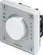
sensorTemperature sensor, setpoint correction Temperature sensor, setpoint correction, occupancy, fan
Temperature sensor, setpoint correction, occupancy, fan, and control of lighting and window blinds
Use ecos 5, ecos311
Interface RS-485
Indicator/display
Type designation
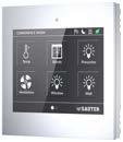

EY-RU365F0**
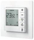
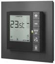
EY-RU355F***

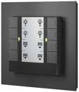
EY-SU358F081
Product name ecoUnit365 ecoUnit355 ecoUnit358
Housing colour
Function
Traffic white/jet black Traffic white/jet black Traffic white/jet black
Temperature sensor, 12 setpoints with 4 functions (temperature, lights, blinds and fans)
Temperature sensor, setpoint correction, occupancy, fan
Push-button unit
Use modulo 6, ecos 5 modulo 6, ecos 5, ecos 311Connection to ecoUnit355
Interface SLC/RS-485
Indicator/display TFT colour display
Button functions 32 on 6 pages with 6 tiles each
Fan speeds
Setpoint correction Digitally adjustable via buttons
412
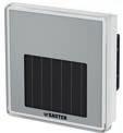
Type designation
EY-RU110F201
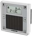
EY-RU146F201
2, 4, 8
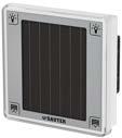
EY-SU106F100
Product name ecoUnit110 ecoUnit146 ecoUnit106
Function
Temperature sensorTemperature sensor, setpoint correction, occupancy, fan, and control of lighting and window blinds
Use With ecosCom581 for: ecos 5, ecos311, modulo 6
Interface EnOcean wireless
Indicator/display
Fan speeds
Setpoint correction
AUTO-0-1-2-3
Digitally adjustable via buttons
Solar panel supply, control of lighting and window blinds
Connection to ecoUnit1**
EY-RU316F001
EY-RU310F001
Features
• Part of the SAUTER modulo 5 system family
• Room operating unit for ecos504/505
• Can be extended with EY-SU 306 push-button unit
• Operating unit to control and guarantee the highest possible room comfort
• Temperature measurement and setpoint adjustment
• Device insert with transparent front, fits into frame with 55 × 55 mm aperture
• Frame can be ordered as an accessory
• Room climate can be adapted individually
• Operating mode can be set for room occupancy and actuation of a 3-speed fan
• Control of window blinds, windows and lighting (ON/OFF/dim)
• Multicolour LED indicators for visualisation of local energy consumption
• Room operating unit with a wide range of functions, designs and colours
Technical data
Power supply
Ambient conditions
Power supply
Current consumption
Operating temperature
Parameters
Sensors
Functionality
From automation station
≤ 25 mA ≤ 38 mA with 2 × EY-SU306
0...45 °C
Storage and transport temperature–25...70 °C
Ambient humidity 10...85% rh, no condensation
Measuring range
Resolution
Time constant
Setpoint correction
0...40 °C
0.1 K
Approx. 7 minutes
Variable
Room occupancy (presence)3 modes, LED indicator
Fan speeds 5 functions, LED indicator
Position LED
Interfaces and communication
Switchable: green/red/OFF
Connection to automation stationActuation ecos 5, modu521
Interface RS-485
Protocol SLC
Cable 4-wire, twisted, shielded
Cable length1) ≤ 100 m (30 m) with bus termination
Connection terminals
Construction
Standards and directives

Pluggable; for wire of 0.12...0.5 mm² (Ø 0.4...0.8 mm)
Fitting Recessed/surface-mounted (see accessories)
Dimensions W × H × D 59.5 × 59.5 × 25 mm
Weight 0.1 kg
Housing
Labelling insert
Pure white (similar to RAL 9010)
Silver (similar to Pantone 877 C)
Type of protection IP30 (EN 60529)
1) Max. 30 m for industrial applications as per EN 61000-6-2
Protection class III (EN 60730-1)
Environment class 3K3 (IEC 60721)
CE conformity according toEMC Directive 2014/30/EUEN 61000-6-1, EN 61000-6-3
Overview of types
Type Features Buttons
EY-RU310F001NTC sensor
EY-RU311F001Operating unit, NTC sensor, dXs setpoint correction (rotary knob)
EY-RU314F001Operating unit, NTC sensor, dXs setpoint correction (rotary knob), fan, occupancy 2
EY-RU316F001Operating unit, NTC sensor, dXs setpoint correction (rotary knob), fan, occupancy, window blinds / light 4
Accessories
Operating unit
Type Description
EY-SU306F001Push-button unit, without frame
Fitting
Type Description
0940240***For frames, mounting plates and adapters for third-party frames, see product data sheet 94.055
0949360004Push-in terminal RU/SU (for wire), 2 × 10 pcs. 2-pin (01/02, 03/04)
0949241301Transparent cover for EY-RU and EY-SU, 10 pcs.
0949241302RAL 9010 white cover for EY-CM581, EY-RU and EY-SU (10 pcs.)
Features
• Part of the SAUTER modulo system family
• High quality room operating unit with touch operation and tile display
• 3.5" TFT colour display, 320x240 pixels
• Scratch-resistant, capacitive touch interface
• Navigation of up to 6 pages with up to 6 functions (tiles) each
• Intuitive operation for predefined functions (temperature, lights, blinds, fans)
• Up to 32 values/channels can be defined as a reference for BACnet objects
• Display of the energy efficiency function (“ECO 10”)
• Mode and symbol displays, e.g. heating/cooling
• Audio feedback when pressed
• Supply voltage 24 VAC/DC
• SLC/RS-485 communicative interface for ecos 5, modulo 6
• Can be located up to 500 m from the automation station
• 6 digital inputs for connecting presence detector, door/window contacts, digital contact directly
• Configuration with CASE Suite (CASE Engine “EY-RU365 module configuration”, RU_TOUCH module)
• Optional: Bluetooth (BLE 4.0) for using the “ecoUnit” app on a smartphone
Technical data
Power supply
Ambient conditions
Operation
Transport
Parameters
Power supply 24 VAC/DC, ±20% – SELV 0 / 50/60 Hz or from EY-PS of station
Rated power during continuous operation < 2.6 W
Operating temperature 0...45 °C
Ambient humidity 10...85% rh, no condensation
Ambient humidity < 85% rh, no condensation
Storage and transport temperature−25...70 °C
Values/channels
Symbol
Number of functions
Tile function
Temperature sensor

Up to 32 values/channels, parameterisable as setpoint, switching command or value display; 12 of which for complete setpoint inputs
Various symbols: e.g. room mode –comfort/reduced/set-back; ECO mode – green-yellow-red; heating/cooling; windows; humidity; wind; alarm; block
Up to 6 pages
Up to 6 tiles per page
Temperature, fan, light dimming, light switching, blind control (position/angle), value displays (feedback), switching function with various predefined symbols (lamp type, mode, scenes...)
Special functions °C/°F changeover for temperature function; home button; navigation display; (title) labelling for pages, tiles and functions
Screensaver display
Type of sensor
None, time, actual temperature or any value (channel)
NTC 10kΩ
Measuring range 0...40 °C
Resolution
Accuracy
0.1 K
± 1 K at typ. 0.1 ms dependent on environment (e.g. air flow)
Refresh interval 1 s
Drift
Position
Inputs
< 0.1 °C/year
Bottom left
Number of inputs 6
Type of inputs
For potential-free switching contacts
Polling voltage 24 VDC unregulated
Polling current >3 mA (closed contact)
Internal resistance > 4.7 kΩ
Input refresh interval 20 ms
Switching thresholds <10 V (voltage “rising”) >6 V (voltage “falling”)
Switching hysteresis >1 V
Audible feedback Type Piezoelectric signal
Application
Display with backlight
Touchpad
Interfaces, communication
Connection terminals
Communication
Audio feedback when touch function is executed
Screen diagonal 3.5 inches (8.9 cm)
Resolution
320 x 240 pixels
Display refresh interval 60 Hz
Type TFT
Number of colours 262,000
Brightness
Contrast ratio
Perspective
Touchpad type
500 cd/m²
300
From above: 15°
From below: 35°
From left/right: 45°
Capacitive with gesture recognition
Refresh rate 10 ms
SLC/RS-485, DI, power supply2 x 6-pin screw terminals, pluggable, for solid or braided wires, max. 1.5 mm² (grid dimension 5 mm)
Actuation
From station (ecos 5, modulo 6)
Interface RS-485 with 115kbit/s (no integrated terminating resistor)
Protocol
SLC
(SAUTER Local Communication)
Cable 2-wire twisted, shielded (D+, D-); MM terminal is reference for RS-485; shielded at controller
Cable length ≤ 500 m with bus termination
Protection circuit
Protected against excess voltage and reversed polarity
Wireless Bluetooth specification 4.0 Low Energy Class 2
Module Panasonic PAN1740
Number of app participants1 simultaneously 256 registered
Supported OS Bluetooth appiOS 8.0 or higher
Android 4.1 (Jelly Bean) or higher
Construction
Device dimensions
Fitting
Dimensions W × H
Recessed mounting
Glass front: 86 × 86 mm²
Plastic housing: 85 × 85 mm²
Surface depth T Max. 15 mm
Recessed depth T (recessed junction box) Min. 34 mm (incl. terminals)
Compatible recessed junction boxesSwiss and European recessed junction boxes
Housing
Colour
Weight Weight
Glass front
Glass type
Glass thickness
Surface hardness
Standards, directives
CE/UKCA conformity1)
F00*: White (similar to RAL 9010)
F0A*: Black (similar to RAL 9005)
F0*1: 0.190 kg
F0*2: 0.200 kg
Float glass, chemically hardened sodalime glass
2.9 mm
6 H
Software class A (EN 60730)
Plastic fire classification UL94V2
Type of protection IP30 (EN 60529)
Protection class III (EN 60730)
Environment class 3K3 (IEC 60721)
EMC-D 2014/30/EU (CE)EN 50491-5-2, EN 50491-5-3
ETSI EN 301 489-1 v.1.9.2
EMC-2016 (UKCA) EN 50491-5-2, EN 50491-5-3
ETSI EN 301 489-1 v.1.9.2
LVD 2014/35/EU (CE) EN 62311
EESR-2016 (UKCA) EN 62311
RED 2014/53/EU (CE) ETSI EN 300 328 v2.1.1
RER-2017 (UKCA) ETSI EN 300 328 v2.1.1
RoHS-D 2011/65/EU & 2015/863/EU (CE)
RoHS-2012 (UKCA)
EN IEC 63000:2018
EN IEC 63000:2018
Other applicable legal actsChemicals REACH Regulation (EC) 1907/2006
Waste electrical and electronic equipment WEEE Directive 2012/19/EU
Overview of types
Type Title
EY-RU365F001ecoUnit365, white, touch, NTC, 6DI
EY-RU365F002ecoUnit365, white, touch, NTC, 6DI, Bluetooth
EY-RU365F0A1ecoUnit365, black, touch, NTC, 6DI
EY-RU365F0A2ecoUnit365, black, touch, NTC, 6DI, Bluetooth
1) Explanation of abbreviations in the “Further information” section of the product data sheet and in the appendix to SAUTER’s product catalogues
Features
• Part of the SAUTER modulo system family
• Room operating unit for ecos311, ecos504/505, modu680/660-AS, ASV2 and A*M***SA
• Local, intuitive operation for temperature, fan and occupancy
• Large backlit (BL) display for status information on the room condition
• Ergonomic buttons with mechanical, tactile feedback
• Individual adjustment of the room climate via temperature detection and setpoint adjustment
• Operating mode can be set for room occupancy and actuation of a 3-speed fan
• ECO button for resetting to automatic mode
• Multicolour LED indicator for visualisation of energy consumption or as position LED
• Sturdy surface of front cover
• Fits into standard frame with 55 × 55 mm aperture
• Individually assignable buttons with different symbols, can be ordered as accessories
• Expandable with EY-SU 358 switching unit for operating lights, window blinds etc.
• Frame can be ordered as an accessory
• Room operating unit with various functions, designs and colours
Technical data
Power supply
Power supply
Current consumption
Ambient conditions
Parameters
Sensors
Functionality
Interfaces, communication
Connection to automation station, controller
Operating temperature
F***: 12...24 VDC, ±20% (with BL)
F0**/A**: 5 VDC, ±20% (without BL) from ecos 5/ecos311/ASV2: 5 VDC from ecos311: 15 VDC from EY-PS, modu6**-AS, A*M-SA: 24 VDC
≤ 7 mA (at 24 VDC, with BL)
≤ 10 mA (at 15 VDC, with BL)
≤ 9 mA (at 5 VDC, without BL)
≤ 12 mA with 2 x EY-SU 358 (24 VDC)
0...45 °C
Storage and transport temperature-25...70 °C
Ambient humidity 10...85% rh, no condensation
Measuring range
Resolution
0...40 °C
0.1 K
Time constant 14 min.
Measuring accuracy
Setpoint correction
0.5 K in the 15...35 °C range
Can be set and reset; LCD
Room occupancy (presence)3 modes; LCD
Fan speeds
Position/energy LED
3 levels, off, automatic; LCD
1; green, red, orange, OFF; switchable Symbols in LCD Time/date, air quality, heating/cooling, ECO, different units, state symbols (window, dew point, locked), SAUTER logo (can be hidden)
Actuation
ecos 5**, ecos311, modu6*0-AS, ASV215, A*M***SA
Interface RS-485
Protocol SLC
EY-RU355F051
EY-RU355FA51

Construction
Cable 4-wire, twisted, shielded
Cable length1) ≤ 100 m with bus termination
Connection terminals Pluggable, for wire 0.12...0.5 mm² (Ø 0.4...0.8 mm)
Fitting
Recessed/surface-mounted (see accessories)
Dimensions W × H × D 55 × 55 × 23 mm
Weight 0.05 kg
Housing
Button printing
Standards, directives
CE/UKCA conformity2)
Type of protection
F0xx/F1xx: traffic white
FAxx/FBxx: jet black
F0xx/F1xx: black
FAxx/FBxx: white
IP30 (EN 60529)
Protection class III (EN 60730-1)
Environment class 3K3 (IEC 60721)
EMC-D 2014/30/EU (CE)EN 61000-6-1, EN 61000-6-2, EN 61000-6-3, EN 61000-6-4
EMC-2016 (UKCA)
RoHS-D 2011/65/EU & 2015/863/EU (CE)
RoHS-2012 (UKCA)
Overview of types
Type Features
EY-RU355Fx02Operating device, LCD, NTC, 0B
EN 61000-6-1, EN 61000-6-2, EN 61000-6-3, EN 61000-6-4
EN IEC 63000:2018
EN IEC 63000:2018
Buttons _ = dummy button, PRES = Presence
No buttons supplied
EY-RU355Fx21Operating device, LCD, NTC, 2B + | - | _ | _ | _
EY-RU355Fx31Operating device, LCD, NTC, 3B
| - | _ | _ | PRES
EY-RU355Fx32Operating device, LCD, NTC, 3B + | - | _ | FAN | _
EY-RU355Fx41Operating device, LCD, NTC, 4B + | - | _ | FAN | PRES
EY-RU355Fx42Operating device, LCD, NTC, 4B + | - | ECO | _ | PRES
EY-RU355Fx51Operating device, LCD, NTC, 5B + | - | ECO | FAN | PRES
EY-RU355Fx52Operating device, LCD, NTC, 5B + | - | UP | DOWN | PRES
EY-RU355Fx53Operating device, LCD, NTC, 5B + | - | UP | DOWN | LIGHT
EY-RU355Fx54Operating device, LCD, NTC, 5B + | - | ECO | FAN | °C/°F
EY-RU355Fx55Operating device, LCD, NTC, 5B + | - | UP | DOWN | FAN
A All types:
x = 0 ≙traffic white, 5/12…24 VDC
x = 1 ≙traffic white, 12…24 VDC (available on request)
x = A ≙jet black, 5/12…24 VDC
x = B ≙jet black, 12…24 VDC (available on request)
Accessories
Type Description
Colour
EY-SU358F021Push-button unit with 2 button functionsTraffic white
EY-SU358FA21Push-button unit with 2 button functionsJet black
EY-SU358F041Push-button unit with 4 button functionsTraffic white
EY-SU358FA41Push-button unit with 4 button functionsJet black
EY-SU358F081Push-button unit with 8 button functionsTraffic white
EY-SU358FA81Push-button unit with 8 button functionsJet black
1) SLC/RS-485 permits a cable length of up to 500 m (decentralised supply)
2) Explanation of abbreviations in the «Further information» section of the product data sheet and in the appendix to SAUTER’s product catalogues
Fitting accessories, spare parts
Type Description
0940240***For frames, mounting plates and adapters for third-party frames, see product data sheet 94.055 0940240103Frame, single, recessed, white (RAL9016), 10 pcs. 0940240104Frame, single, recessed, black (RAL9005), 10 pcs. 0940240703Mounting plate, single, for recessed fitting (10 pcs.) 0940240203Frame, double, recessed, white (RAL9016), 10 pcs. 0940240204Frame, double, recessed, black (RAL9005), 10 pcs. 0940240802Mounting plate, double, for recessed fitting (10 pcs.) 0940240302Frame, single, surface-mounted, white (RAL9016), 10 pcs. 0940240303Frame, single, surface-mounted, black (RAL9005), 10 pcs. 0940240402Frame, double, surface-mounted, white (RAL9016), 10 pcs. 0940240403Frame, double, surface-mounted, black (RAL9005), 10 pcs. 094013****Buttons as accessories/spares, 10 pcs. (see product data sheet 94.055) 0949360004Push-in terminal RU/SU (for wire), 2 × 10 pcs. 2-pin (01/02, 03/04) 0940360005Terminal RU-SU, push-in, @3P (V,C,DQ), 10 pcs. (accessory for EY-SU 358) 0940360007Terminal RU-SU, screw, @3P (V,C,DQ), 10 pcs. (optional accessory for EY-SU 358) 0940360006Terminal and cable RU-SU, @3P (V,C,DQ), 15 cm, 10 pcs. (optional accessory for EY-SU 358) 0940360012Screw terminal RU/SU (optional for stranded cable), 2 × 10 pcs. 2-pin (01/02, 03/04)
EY-SU358F081
EY-SU358FA81
EY-SU 358: Push-button unit for room operating unit, ecoUnit358
Features
• Part of the SAUTER modulo system family
• Push-button unit to supplement the ecoUnit355 (EY-RU 355)
• Various designs and colour versions in black and white
• For controlling window blinds and lighting (on/off, dim)
• 2, 4 or 8 button functions
• Labelling insert for individual labelling
• Fits into frame with 55 × 55 mm aperture
• Frame can be ordered as an accessory
Technical data
Power supply
Ambient conditions
Parameters
Functionality
Connection
Labelling
Construction
Power supply
From ecoUnit355
Current consumption ≤ 2.5 mA (at 24 V= for ROU) ≤ 3 mA (at 15 V= for ROU) ≤ 8.5 mA (at 5 V= for ROU)
Operating temperature 0...45 °C
Storage and transport temperature−25...70 °C
Ambient humidity 10...85% rh, no condensation
Position LED 2; green, red, orange, off; can be connected parallel to EY-RU 355 LED
Cable 3-wire (V, C, DQ)
Length ≤ 30 m (can be installed remotely from ecoUnit355)
Labelling insert 1 to 3, depending on type; Colour: silver (similar to Pantone 877 C)
Fitting
Recessed/surface-mounted (see list of accessories)
Dimensions W × H × D 55 × 55 × 23 mm
Weight 0.04 kg
Buttons
Standards, directives
Type of protection
F021: two (dual buttons, dummy buttons)
F041: four (dual buttons)
F081: eight (single buttons)
IP30 (EN 60529)
Protection class III (EN 60730-1)
Environment class 3K3 (IEC 60721)
CE conformity according toEMC Directive 2014/30/EUEN 61000-6-1, EN 61000-6-2, EN 61000-6-3, EN 61000-6-4

Type Description Colour
EY-SU358Fx21Push-button unit, ecoUnit358, 2T
EY-SU358Fx41Push-button unit, ecoUnit358, 4T
EY-SU358Fx81Push-button unit, ecoUnit358, 8T
Accessories
Type Description
x=0, traffic white x=A, jet black
x=0, traffic white x=A, jet black
x=0, traffic white x=A, jet black
0940360005Terminal RU-SU, push-in, @3P (V,C,DQ), 10 pcs. (accessory for EY-SU 358)
0940360007Terminal RU-SU, screw, @3P (V,C,DQ), 10 pcs. (optional accessory for EY-SU 358)
0940360006Terminal and cable RU-SU, @3P (V,C,DQ), 15 cm, 10 pcs. (optional accessory for EY-SU 358)
0940240***For frames, mounting plates and adapters for third-party frames, see product data sheet 94.055 0940240103Frame, single, recessed, white (RAL9016), 10 pcs. 0940240104Frame, single, recessed, black (RAL9005), 10 pcs. 0940240703Mounting plate, single, for recessed fitting (10 pcs.)
0940240203Frame, double, recessed, white (RAL9016), 10 pcs. 0940240204Frame, double, recessed, black (RAL9005), 10 pcs. 0940240802Mounting plate, double, for recessed fitting (10 pcs.)
0940240302Frame, single, surface-mounted, white (RAL9016), 10 pcs. 0940240303Frame, single, surface-mounted, black (RAL9005), 10 pcs. 0940240402Frame, double, surface-mounted, white (RAL9016), 10 pcs. 0940240403Frame, double, surface-mounted, black (RAL9005), 10 pcs. 0940001501Blank foil for EY-SU 358, silver, (10 pcs.)
094013****Buttons as accessories/spares, 10 pcs. (see product data sheet 94.055)
Features
• Part of the SAUTER modulo system family
• Room sensor with integrated digital temperature sensor
• Compatible with ecosCom581 and EnOcean interfaces from third-party manufacturers
• Battery-free with integrated solar panel
• Expandable with ecoUnit106 as additional solar panel supply
• Device insert with transparent front, fits into frame with 55 x 55 mm aperture
• Frame can be ordered as an accessory
• Frames and foils in many colours and designs possible
Technical data
Power supply

Parameters
Power supply
3 V, from integrated solar panel (external battery operation optional)
Illuminance Min. 250 lux, min. 5 hours daily in 5 of 7 days
Dark period1) 60 h of full operation, additional 7 days at least in low power mode
Technology
EnOcean, STM 300
Frequency 868 MHz band (868.3 MHz)
Range
Sensor (temperature)
Ambient conditions3)
Interfaces, communication
Construction
Up to 30 m, depending on building structure (planning recommendation: 10 m)
Measuring range 0…40 °C
Resolution2) 0.2 K (hysteresis)
Time constant Approx. 7 min.
Measuring accuracy, temperatureTyp. 0.5 K in the 15…35 °C range
Operating temperature 0...45 °C
Storage and transport temperature−25…70 °C
Ambient humidity 5…85% rh, no condensation
Connection4)
No wiring necessary, teach-in (pairing) with ecosCom581 or ecoMod580 wireless interface via SLC/RS-485
EnOcean Equipment Profile5) EEP: A5-10-01 (unidirectional)
Weight
0.05 kg
Dimensions W × H × D 59.5 × 59.5 × 27.8 mm
Housing Pure white (similar to RAL 9010)
Labelling insert Silver (similar to Pantone 877 C)
1) Bridging time without lighting when the internal energy storage/battery is fully charged
2) Measurement value hysteresis for spontaneous transmission (EnOcean telegram)
3) The device may be active during transport. The device is equipped with a permanently installed lithium cell (energy storage/battery)
4) See quick reference for ecosCom581/ecoMod580
5) EEP V2.6.8 or higher
The ecoUnit110 room sensor currently only supports the temperature value of EEP A5-10-01 and no other EEP as a temperature sensor, such as A5-02-05 (temp. sensor 0...40 °C)
Standards, directives
Fitting
Type of protection
Recessed/surface-mounted (see accessories)
IP30 (EN 60529)
Protection class III (EN 60730-1)
Environment class 3K3 (IEC 60721)
CE conformity according toEMC Directive 2014/30/EUEN 61000-6-1, EN 61000-6-3
Low-Voltage Directive 2014/35/EUEN 60730-1
RED 2014/53/EU
ETSI EN 300220‑2 (V3.1.1)
RoHS Directive 2011/65/EUEN IEC 63000
Overview of types
Type Description
EY-RU110F201Room sensor, EnOcean, temperature sensor, solar panel
A The device is supplied with a silver-coloured labelling insert. Spare inserts: 0940001510 (10 pcs.)
A Order frame and mounting plate separately (see accessories)
Accessories
Type Description
EY-SU106F100Push-button unit with solar panel, 6 push-buttons, without frame 0940240***For frames, mounting plates and adapters for third-party frames, see product data sheet 94.055 0949241301Transparent cover for EY-RU and EY-SU, 10 pcs. 0949360004Push-in terminal RU/SU (for wire), 2 × 10 pcs. 2-pin (01/02, 03/04) 0940360012Screw terminal RU/SU (optional for stranded cable), 2 × 10 pcs. 2-pin (01/02, 03/04) 0949570001Battery pack, 10 pcs. 0940001510Labelling insert, foil, silver, without button symbols, 10 pcs.
A EY SU106F100: Can be used as an extended solar panel for the EY-RU110F201 room sensor, but not as a pushbutton unit.
A 0949570001: Suitable as energy supply in permanently darkened rooms.
Features
• Part of the SAUTER modulo system family
• Room operating unit with integrated digital temperature sensor
• Bidirectional and compatible with ecosCom581 (EnOcean SMART ACK)
• Compatible with EnOcean interfaces of third-party manufacturers
• Battery-free with LCD, ecoUnit106 push-button unit can be added
• Display with extensive status information on room conditions
• Device insert with transparent front, fits into frame with 55 x 55 mm aperture
• Room climate can be adapted individually
• Selection of three operating modes for room occupancy
• Control of a fan with three speed levels
• Control of window blinds, windows and lights (on/off/dim)
• Frame can be ordered as an accessory
• Frames and foils in many colours and designs possible
Technical data
Power supply
Power supply
3 V, from integrated solar panel (external battery operation optional) Illuminance Min. 250 lux, min. 5 hours daily in 5 of 7 days
Dark period1)
Parameters
Sensor (temperature)
Technology
50 h of full operation, 60 h all of most important functions, additional 7 days at least in low power mode
EnOcean, STM 300
Frequency 868 MHz band (868.3 MHz)
Range Up to 30 m, depending on building structure
(planning recommendation: 10 m)
Measuring range 0…40 °C
Resolution2)
Time constant
Ambient conditions3)

Function
0.1 K (display), 0.2 K (hysteresis)
Approx. 7 min.
Measuring accuracy, temperatureTyp. 0.5 K in the 15...35 °C range
Operating temperature
0…45 °C
Storage and transport temperature−25…70 °C
Ambient humidity 5…85% rh, no condensation
Setpoint correction
Adjustable and resettable
Room occupancy (presence)3 modes, LCD
Fan speeds 5 functions, LCD
1) Bridging time without lighting when the internal energy storage/battery is fully charged
2) 0.2 K (hysteresis): Measurement value hysteresis for spontaneous transmission (EnOcean telegram)
3) The device may be active during transport. The device is equipped with a permanently installed lithium cell (energy storage/battery)
Interfaces, communication
Connection4)
EnOcean Equipment Profile5)
Construction
Weight
Housing
Labelling insert
Fitting
Standards, directives
Type of protection
No wiring necessary, teach-in (pairing) with ecosCom581 or ecoMod580 wireless interface via SLC/RS-485
EEP: D2-00-01 (bidirectional, SMART ACK)
EEP: A5-10-01 (unidirectional)
EEP: F6-03-01 (buttons 3, 4, [7…12 with ecoUnit106])
0.055 kg
Pure white (similar to RAL 9010)
Silver (similar to Pantone 877 C)
Recessed/surface-mounted (see accessories)
IP30 (EN 60529)
Protection class III (EN 60730-1)
Environment class 3K3 (IEC 60721)
CE conformity according toEMC Directive 2014/30/EUEN 61000-6-1, EN 61000-6-3
Low-Voltage Directive 2014/35/EUEN 60730-1
RED 2014/53/EU
ETSI EN 300220‑2 (V3.1.1)
RoHS Directive 2011/65/EUEN IEC 63000
Overview of types
Type Description
EY-RU146F201Room operating unit, EnOcean, LCD, temperature sensor, solar panel, 6 buttons: dXs setpoint correction (+/-), fan, presence, 2 free buttons (window blind/light)
A The device is supplied with a silver-coloured labelling insert. Spare inserts: 0940001533 (10 pcs.)
A Order frame and mounting plate separately (see accessories)
Accessories
Type Description
EY-SU106F100Push-button unit with solar panel, 6 push-buttons, without frame 0940240***For frames, mounting plates and adapters for third-party frames, see product data sheet 94.055 0949241301Transparent cover for EY-RU and EY-SU, 10 pcs.
0949360004Push-in terminal RU/SU (for wire), 2 × 10 pcs. 2-pin (01/02, 03/04)
0940360012Screw terminal RU/SU (optional for stranded cable), 2 × 10 pcs. 2-pin (01/02, 03/04)
0949570001Battery pack, 10 pcs.
0940001511Labelling insert, foil, silver, (symbols: +, −), 10 pcs.
0940001521Labelling insert, foil, silver, (symbols: +, −, presence), 10 pcs.
0940001522Labelling insert, foil, silver, (symbols: +, −, fan), 10 pcs.
0940001523Labelling insert, foil, silver, (symbols: +, −, presence, fan), 10 pcs.
0940001531Labelling insert, foil, silver, (symbols: +, −, presence, two lights), 10 pcs.
0940001532Labelling insert, foil, silver, (symbols: +, −, fan, two lights), 10 pcs.
0940001533Labelling insert, foil, silver, (symbols: +, −, presence, fan, two lights), 10 pcs.
4) See quick reference for ecosCom581/ecoMod580
5) EnOcean Equipment Profile (EEP) V2.6.8 or higher
Features
• Part of the SAUTER modulo system family
• Integrated solar cell for additional solar panel supply of ecoUnit 1 EnOcean devices
• Push-button unit to supplement the ecoUnit14* room operating unit
• Control of window blinds and lighting (on/off, dim)
• Up to six button functions
• Device insert with transparent front, fits into frame with 55 x 55 mm aperture
• Frame can be ordered as an accessory
• Frames and foils in many colours and designs possible
Technical data
Power supply
Parameters
Connection
Ambient conditions
Construction

Standards and directives
Power supply1) Not required
Cable 4-wire
Length2) ≤ 1 m
Operating temperature 0…45 °C
Storage and transport temperature−25…70 °C
Ambient humidity 10…85% rh, no condensation
Fitting
Recessed/surface-mounted (see accessories)
Dimensions W × H × D 59.5 × 59.5 × 27.8 mm
Weight 0.047 kg
Type of protection
IP30 (EN 60529)
Protection class III (EN 60730-1)
Environment class 3K3 (IEC 60721)
CE conformity according toEMC Directive 2014/30/EUEN 61000-6-1, EN 61000-6-3
RoHS Directive 2011/65/EUEN IEC 63000
Overview of types
Type Features
EY-SU106F100Push-button unit with up to 6 button functions, integrated solar cell
Accessories
Type Description
0940240***For frames, mounting plates and adapters for third-party frames, see product data sheet 94.055
0949241301Transparent cover for EY-RU and EY-SU, 10 pcs.
0949360004Push-in terminal RU/SU (for wire), 2 × 10 pcs. 2-pin (01/02, 03/04)
0940360012Screw terminal RU/SU (optional for stranded cable), 2 × 10 pcs. 2-pin (01/02, 03/04)
0940001541Labelling insert, foil, silver, (symbols: two lights, two window blinds), 10 pcs.
0940001542Labelling insert, foil, silver, (symbols: two lights), 10 pcs.
0940001543Labelling insert, foil, silver, (symbols: two window blinds), 10 pcs.
1) The power supply is provided by the connected device (ecoUnit14* or ecoUnit110)
2) See connection diagram
Features
• Part of the SAUTER modulo system family
• Bidirectional wireless communication according to EnOcean (ISO/IEC 14543-3-10)
• Internal, optimised wireless antenna (no BNC antenna necessary)
• Integration of EnOcean devices: SAUTER ecoUnit110 room sensor and ecoUnit146 room operating unit and other EnOcean devices from third-party manufacturers
• Wide-range supply voltage for compatibility with ecos 5 and ecos311 room controllers and modulo 6 automation stations
• RS-485 interface for remote, optimum positioning of the wireless interface in the room
• Firmware update via SLC/RS-485
• Device insert with transparent front, fits into frame with 55 x 55 mm aperture
• Frame and white cover front can be ordered as accessories
• Frames and foils in many colours and designs possible
Technical data
Power supply
Power supply
Current consumption
Ambient conditions
Operating temperature
Interfaces and communication
5…24 V DC ±20% ecos 5:+5 V, ecos311:+15 V/+5 V, modulo 6:+24 V
5 V: typ. 36 mA, 68 mA peak
15 V: typ. 14 mA, 24 mA peak
24 V: typ. 10 mA, 17 mA peak
0...45 °C
Storage and transport temperature−25…70 °C
Ambient humidity
Wireless technology
5…85% rh, no condensation
EnOcean, TCM 300
Frequency 868 MHz band (868.3 MHz)
Protocol
Range
EnOcean EEP (see EEP list)
Up to 30 m, depending on building structure (planning recommendation: 10 m)
Connection to automation stationInterface RS-485, 115.2 kbit/s
Protocol
Construction
Standards and directives
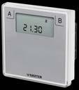
SLC (SAUTER Local Communication)
Actuation ecos 5, ecos311, modulo 6
Line 4-wire twisted (shielding, RS-485:line end resistance recommended)
Line length ≤ 100 m
Weight
0.07 kg
Dimensions W × H × D 59.5 × 59.5 × 27.8 mm
Housing
Pure white (similar to RAL 9010)
Labelling insert Silver (similar to Pantone 877 C)
Fitting
Type of protection
Recessed/surface-mounted (see accessories)
IP30 (EN 60529)
Protection class III (EN 60730-1)
Environment class 3K3 (IEC 60721)

CE conformity according toEMC Directive 2014/30/EUEN 61000-6-1, EN 61000-6-3
Low-Voltage Directive 2014/35/EUEN 60730-1
RED 2014/53/EU ETSI EN 300220‑2 (V3.1.1)
RoHS Directive 2011/65/EUEN IEC 63000
Overview of types
Type Description
EY-CM581F081COM module EnOcean, SLC/RS-485, 5...24 V DC, 868 MHz
Accessories
Type Description
0940240***For frames, mounting plates and adapters for third-party frames, see product data sheet 94.055
0949241301Transparent cover for EY-RU and EY-SU, 10 pcs.
0949241302RAL 9010 white cover for EY-CM581, EY-RU and EY-SU (10 pcs.)
0949360004Push-in terminal RU/SU (for wire), 2 × 10 pcs. 2-pin (01/02, 03/04)
0940360012Screw terminal RU/SU (optional for stranded cable), 2 × 10 pcs. 2-pin (01/02, 03/04)
Smart multi-sensors in a mesh network for precise detection of presence/motion, brightness, temperature, humidity, air quality (VOC, CO2) and noise levels in rooms or room zones for optimum indoor air and indoor environment quality

Type designation
Product name viaSens116 viaSens117 viaSens196 viaSens197
Housing colour
Traffic white / jet black
Traffic white / jet black
Function Node IoT gateway
Sensors
Temperature sensor (digital / TFIR)
HUM humidity sensor (digital)
VOC sensor (air quality, digital)
CO2 sensor (air quality, digital)
PIR sensor (presence and motion detector)
LUX light sensor (brightness, digital)
SPL sound pressure sensor (noise level)
Display and operation
LED ring
Push-button, capacitive
Interfaces, communication
12 LEDs, RGB colours
Interfaces Bluetooth mesh, Bluetooth beacon, Wi-Fi, NFC, UARTEthernet, Bluetooth mesh, Bluetooth beacon, Wi-Fi, NFC, UART
IP/Ethernet protocols
Bluetooth Low energy, mesh, beacon, relay
Bluetooth mesh profile
Sensor server model
Further information Page 428
MQTT client: TCP, TLS, WS, WSS
Low energy, mesh, beacon
Sensor server and client model
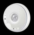
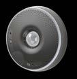
Features
• Measurement of indoor air quality (IAQ1)), such as temperature, humidity and air quality (VOC2), CO2: 3)).
• Measurement of indoor environment quality (IEQ4)), such as motion/presence, brightness and sound pressure level
• Sensor values can be used for more precise information on the state of the room (sensor fusion)
• For ceiling mounting (recessed/surface-mounted)
• Minimal sensor wiring thanks to Bluetooth®5) Mesh network
• Controllable coloured LED ring for displaying the room status to room users
• Parameterisable animation profiles for LED ring, e.g. room reserved/available, room air quality good/bad, room ready for cleaning, etc.)
• Bluetooth Beacon function for locating the room user with a smartphone and optimised use of SAUTER Mobile Building Services (Mobile Room Control app)
• IoT ready thanks to encrypted MQTT communication as MQTT client of FMS 19x sensor gateway
• For up to 16 sensors for an ecos504/505 room controller
• Simple integration into the SAUTER automation system with the FMS 19x sensor gateway thanks to CASE Suite and Bluetooth smartphone app
• Meshing of up to 15 FMS 116, 117 sensors via Bluetooth mesh technology to the FMS 19x sensor gateway
Technical data
Power supply
Power supply 12…34 VDC, typ. 24 VDC
Current consumption Max. 80 mA at 24 VDC
Power consumption
Parameters6)
Temperature (TDIG)
Temperature (TFIR)
Relative humidity (HUM)
Air quality (VOC)
Air quality (CO2) (FMS 117, 197 only)
1) IAQ: indoor air quality
2) VOC: volatile organic compounds

Typ. 2 W
Measuring principle CMOS technology (SHT40)
Measuring range 0…40°C
Resolution
Time constant
0.1 K
Approx. 8 s (dew 63%)
Measuring principle Far infrared (MLX)
Measuring range 15…40°C
Resolution 0.1 K
Measuring accuracy7) ±1 K
Emissivity 0...100%, parameterisable
Field of view (FOV) 50°
Measuring principle CMOS technology (SHT40)
Measuring range 0...100%, typ. 20...80% rh
Resolution 1%
Measuring accuracy ±2% in 10…90% range at 25°C.
Time constant Approx. 8 s (dew 63%)
Measuring principle CMOS technology (SGP40)
Measuring range 1…500 VOC index
Resolution 1 VOC index
Time constant < 10 s (dew 63%)
Measuring principle
Photoacoustic NDIR (SCD40)
Measuring range 400…2000 ppm
3) CO2: Carbon dioxide concentration - FMS 117, 197 only
4) IEQ: indoor environment quality
5) The Bluetooth® word mark and logos are registered trademarks of Bluetooth SIG, Inc.
6) For explanations, see the “Abbreviations (sensor types and functions)” list
7) Thermal objects can affect the measuring accuracy
Motion, presence (PIR)
Brightness (LUX)
Sound pressure level (SPL)
Technology
Ambient conditions
Resolution
Measuring accuracy
Measuring principle
Detection range8)
Field of view (FOV)
Fresnel lens
Measuring principle
Measuring range
Resolution
Field of view (FOV)
Measuring range
Frequency spectrum
Filter type
Sensitivity
Processor
Operating temperature
Display and operation
1 ppm
±50 ppm (±5% MV)
Four-element IR detector (PYQ)
Ø 9 m and approx. 8 × 8 m area at 2.5 m fitting height,
360° tangential and radial
120°
34 zones
Digital light sensor (APDS)
0…16 000 lux
1 lux
140°
0...120 dB(A)
60…20 000 Hz
A weighting
−26 dB on the measuring range, ±1 dB tolerance
Dual-Core ARM Cortex, 32-bit, 240 MHz
0…45°C
Storage and transport temperature−25…70°C
Ambient humidity
Display9)
Push-button, capacitive
Interfaces, communication
Bluetooth mesh Network
Radio frequency
Range10)
Bluetooth mesh profile
Localisation
Ethernet (FMS 196, 197 only)Ethernet network
10…80% rh, no condensation
LED ring with 12 LEDs, RGB colours (red, green, blue; 6 bit RGB)
Configurable animation profiles with 16 predefined colours
Identification, service menu, restart, factory reset (front)
Bluetooth mesh node (2.4 GHz), up to 8 TTL hops
2.4 GHz (5 dBm)
Up to 10 m
FMS 116, 117: Bluetooth mesh relay node, sensor-node (sensor server model, V1.0)
FMS 196, 197: Bluetooth mesh, sensor gateway (sensor server + client model, V1.0)
Bluetooth beacon (iBeacon), indoor position determination
1 × RJ-45 connector
10/100 BASE-T(X) 10/100 Mbit/s
Communication protocol
NFC (near field communication)11)
Slide switch12)
Serial port
WiFi (802.11 a/b/g/n)
MQTT client V3.1.1/V5, MQTT(S), TLS V1.2, WS(S) (ISO/IEC 20922)
Product data and configuration parameters
(De)activation of sound pressure level (rear)
UART for firmware update (point to point), 3.3 V TTL
WLAN client deactivated, can be temporarily activated for firmware update with app
8) As per IEC 63180:2020
9) Example application: Presence: LED ring off/blue, room climate/air quality: LED ring green/red
10) Depending on building and room structure; planning recommendation: max. 10 m between two Bluetooth mesh nodes
11) The function with NFC is not supported by the current version 2 of the «viaSens» app
12) Switching only takes effect when the power is off
Construction
Dimensions13)
Housing material
Fitting14)
Standards, directives
Surface Ø × D: 103 × 30 mm
Recessed Ø × D: min. 50 × 35 mm
Thermoplastic (PC, PC-ABS)
Recessed, surface and hollow ceiling mounting
Fitting height 2.5…3.5 m (ceiling)
Type of protection
CE conformity15)
IP20 (IEC 60730)
Protection class III
Environment class 3K3 (IEC 60721)
Plastic fire classification UL94
EMC-D 2014/30/EU (CE)EN 301489 (EMC for radio equipment)
LVD 2014/35/EU (CE)
RED 2014/53/EU (CE)
RoHS-D 2011/65/EU & 2015/863/EU (CE)
EN 60730-1 (residential premises)
EN 60730-1, EN 62311
ETSI EN 300 328 (V2.2.2), 2.4 GHz band
EN IEC 63000
Overview of types
Type Description WeightHousing
FMS116F121Smart sensor with Bluetooth mesh, TDIG, TFIR, HUM, VOC, PIR, LUX, SPL
0.2 kg Traffic white
FMS116F121ASmart sensor with Bluetooth mesh, TDIG, TFIR, HUM, VOC, PIR, LUX, SPL 0.2 kg Jet black
FMS117F121Smart sensor with Bluetooth mesh, TDIG, TFIR, HUM, VOC, CO2, PIR, LUX, SPL 0.2 kgTraffic white
FMS117F121ASmart sensor with Bluetooth mesh, TDIG, TFIR, HUM, VOC, CO2, PIR, LUX, SPL 0.2 kgJet black
FMS196F121Smart sensor with MQTT/ETH, Bluetooth mesh, TDIG, TFIR, HUM, VOC, PIR, LUX, SPL 0.3 kgTraffic white
FMS196F121ASmart sensor with MQTT/ETH, Bluetooth mesh, TDIG, TFIR, HUM, VOC, PIR, LUX, SPL 0.3 kgJet black
FMS197F121Smart sensor with MQTT/ETH, Bluetooth mesh, TDIG, TFIR, HUM, VOC, CO2, PIR, LUX, SPL
FMS197F121ASmart sensor with MQTT/ETH, Bluetooth mesh, TDIG, TFIR, HUM, VOC, CO2, PIR, LUX, SPL
0.3 kgTraffic white
0.3 kgJet black
A The Ethernet interface for types FMS 196, 197 is used as a sensor gateway for the Bluetooth mesh network and for integrating the sensor network in the automation system with MQTT via TCP/TCP+TLS (MQTT/MQTTS) or via web socket (WS/WSS)
A Housing: matt, traffic white similar to RAL 9016, jet black similar to RAL 9005
Abbreviations (sensor types and functions)
CO2 Measurement of carbon dioxide in the room air with digital measuring element
FOVField of view
HUMMeasurement of relative humidity with digital measuring element
LUXMeasurement of illuminance
MQTT/ETHEthernet interface for MQTT
PIRMotion and presence detection with passive infrared sensor
SPLMeasurement of sound pressure level
13) For dimensions of accessories, see fitting instructions
14) Recessed mounting with box at least 45 mm deep for FMS 116, 117 and at least 61 mm deep for FMS 196, 197 (Ethernet cable bending radius). Mounting in hollow ceiling with spring clamps, at ceiling thickness 2…20 mm hole diameter 68 mm; at 20…25 mm hole diameter 75 mm. Surface mounting with box 28 mm deep for FMS 116, 117 and 53 mm deep for FMS 196, 197
15) Explanation of abbreviations in the “Additional technical information” section of the product data sheet and in the appendix to SAUTER product catalogues
TDIGTemperature measurement with digital measuring element
TFIRTemperature measurement with far infrared temperature element
VOCMeasurement of volatile organic compounds
Accessories
Type Delivery quantityDescription
09402411011 pcs.
Mounting plate, recessed, white
0940241101A1 pcs. Mounting plate, recessed, black
0940241110Set of 10Mounting plate, recessed, white
0940241110ASet of 10Mounting plate, recessed, black 09402412011 pcs. Mounting plate, surface, 53 mm, white 0940241201A1 pcs. Mounting plate, surface, 53 mm, black 0940241210Set of 10Mounting plate, surface, 53 mm, white 0940241210ASet of 10Mounting plate, surface, 53 mm, black 09402413011 pcs. Mounting plate, surface, 28 mm, white 0940241301A1 pcs. Mounting plate, surface, 28 mm, black 0940241310Set of 10Mounting plate, surface, 28 mm, white 0940241310ASet of 10Mounting plate, surface, 28 mm, black 09402414202 sets of 10Mounting spring, false ceiling 0940241510Set of 10PIR orifice plate, 180° angle (half), white 0940241510ASet of 10PIR orifice plate, 180° angle (half), black 0949360014Set of 10Terminal, 2-pin, push-in, @2×2P (green)
A The sensors are supplied without mounting accessories. Accessory 0949360014 for power supply connection is supplied
The SAUTER ecoLink modules are remote modules for flexibly expanding the I/O mix of the ecos504/505 and modulo 6 automation stations. The modules are used to capture digital and analogue signals from sensors and HVAC installations. They control valve actuators, dampers, fans, dimmable lamps or sunshade actuators. The remote fitting reduces the wiring needed for the sensors and actuators.

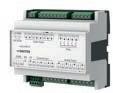
Features
• Part of the SAUTER modulo 5 system family
• Regulation, control, monitoring and optimisation of operational systems, e.g. room automation or HVAC engineering
• Remote I/O module for ecos504/505
• Communicative connection of actuators to automation stations
• Can be located up to 500 m from automation stations
Technical data
Power supply

Ambient conditions
Inputs/outputs
Analogue/digital inputs
Power supply
24 VAC, ±20%, 50...60 Hz
Current consumption ≤ 0.2 A, without load current from Triac and relay outputs
Power consumption ≤ 6.6 VA Triac outputs not under load, ≤ 48 VA Triac outputs with rated load
Dissipated power ≤ 5 W (typically approx. 0.5 W)
Operating temperature 0...45 °C
Storage and transport temperature–25...70 °C
Ambient humidity 10...85% rh, no condensation
Type 0...10 V/O-I
Ni1000/Pt1000-EingängeType -20...100 °C
Relay outputs
Triac outputs
Analogue outputs
Interfaces and communication
Type 0-I, normally-open contacts
Load1) 230 VAC, 5 A (total max. 10 A)
Switching frequency > 3 × 10⁵ cycles
Type 0-I, 24 V~/0.5 A
Type 0...10 V, 2 mA
Actuation From ecos504/505
Interface RS-485
Protocol SLC
Cable 4-wire, twisted, shielded
Cable length2) Up to 500 m with bus termination
Construction
Standards and directives
Dimensions W × H × D 105 × 95 × 60 mm
Weight 0.22 kg
Type of protection3) IP00 (EN 60529)
Protection class II (EN 60730-1) for EY-EM 510, III (EN 60730-1) for EY-EM 511, EY-EM 512
Environment class 3K3 (IEC 60721)
CE conformity according to EMC Directive 2014/30/EU4) EN 61000-6-1, EN 61000-6-2 EN 61000-6-3, EN 61000-6-4
Low-Voltage Directive 2014/35/EUEN 60730-1
1) See the section “Digital outputs (relays)”
2) See the section “Engineering notes”
3) IP20 with terminal cover (accessory 0900240020); IP40 at front when fitted
4) EN 61000-6-2: In order to meet the European Standard, the power cables for the inputs and outputs must not exceed 30 metres in length
Overview of types
Type Description
EY-EM510F001Remote I/O module, 24 V~, 3 relays, 3 Triacs
EY-EM511F001Remote I/O module, 24 V~, 3 Triacs
EY-EM512F001Remote I/O module, 24 V~, 2 Triacs
Accessories
Type Description
0949360003Plug-in connector for ecoLink RS-485, 10 pcs.
0900240020Terminal cover
0450573001Transformer 230 VAC / 24 VAC, 42 VA; for DIN rail 35 mm, dimensions: 78 × 74 × 52 mm (W×H×D)
EY-EM514F001
EY-EM515F001
Features
• Part of the SAUTER modulo 5 system family
• Remote I/O module for ecos504/505
• Communicative, digital connection of actuators and sensors to automation stations
• Activation of actuators for heated/chilled ceilings, recirculated air and fan coil units, and window blinds
• Inputs for presence detectors, temperature sensors, analogue sensors and window contacts
• Can be located up to 500 m from automation stations
Technical data
Power supply
Ambient conditions
Inputs/outputs
Relay outputs
Power supply
24 VAC, ±20%, 50...60 Hz
24 VDC, ±10%
Current consumption Max. 150 mA
Without load current of DO (relay, FET)
Plus up to 0.5 A / FET
Dissipated power Max. 2 W (typically 1.2 W)
Operating temperature 0...45 °C
Storage and transport temperature–25...70 °C
Ambient humidity 10...85% rh, no condensation
Type 0-I relay, normally-open contacts
Load 24...250 V
5 A resistive load
Total max. 10 A
Switching frequency > 3 × 10⁵ cycles
Semiconductor outputs (FET) Type 0-I, 24 VAC/DC, 0.5 A, connected to ground max. peak current 1 A at 20 ms
Analogue outputs Type 0...10 V/2 mA
Universal inputs
Analogue 0...10 V / 0...1 V
Digital 0-I
Resistor 100...2500 Ω
Potentiometer 1...10 kΩ
Ni1000/Pt1000 -20...100 °C
Interfaces, communication
Connection to automation stationActuation
Construction
Standards, directives
From ecos504/505
Interface RS-485
Protocol SLC
Cable 4-wire, twisted, shielded
Cable length1) Up to 500 m with bus termination
Dimensions W × H × D 105 × 95 × 60 mm
Type of protection2) IP00 (EN 60529)
Protection class II (EN 60730-1) for EY-EM 514
III (EN 60730-1) for EY-EM 515
Environment class 3K3 (IEC 60721)

1) See the section “Engineering notes”
2) IP20 with terminal cover (accessory 0900240020); IP40 at front when fitted
CE conformity according toEMC Directive 2014/30/EUEN 61000-6-1, EN 61000-6-2 EN 61000-6-3, EN 61000-6-4
Low-Voltage Directive 2014/35/EUEN 60730-1 (EY-EM 514 only)
Overview of types
Type Description
EY-EM514F001Remote I/O module, 24 V~/=, 4 relays, 6 DO FET, 4 AO, 4 UI
EY-EM515F001Remote I/O module, 24 V~/=, 6 DO FET, 4 AO, 4 UI
Overview of I/O mix
g
g
EY-EM 514EY-EM 515 Normally-open relay contacts 4 –
Semiconductor FET switch (connected to ground) 6 6 Analogue outputs
Accessories
Type Description
0949360003Plug-in connector for ecoLink RS-485, 10 pcs.
0900240020Terminal cover
0450573001Transformer 230 VAC / 24 VAC, 42 VA; for DIN rail 35 mm, dimensions: 78 × 74 × 52 mm (W×H×D)
EY-EM522F001
EY-EM523F001
Features
• Part of the SAUTER modulo 5 system family
• Remote I/O module for ecos504/505
• Switching and dimming of up to four lamps
• Can be located up to 500 m from the automation station
Technical data
Power supply
Power supply
Current consumption
Dissipated power
Ambient conditions
Inputs/outputs
Relay outputs
230 VAC ±10%, 50...60 Hz
Max. 20 mA (typically 14 mA)
Without load current of relays
Max. 2.5 W (typically 1.5 W)
Operating temperature 0...45 °C
Storage and transport temperature–25...70 °C
Ambient humidity 10...85% rh, no condensation
Type 0-I relay, NO contacts
Load
DIM-10V outputs
Analogue outputs
Universal inputs
230 VAC with voltage applied
230 VAC / 5 A resistive load
Total max. 10 A
Switching frequency > 3 × 10⁵ cycles
Type 1...10 V passive output for electronic ballasts as per EN 60929
Electrically isolated
Type 0...10 V / 2 mA
Analogue 0...10 V / 0...1 V
Digital O-I
Resistor 100…2500 Ω
Potentiometer 1...10 kΩ
Ni1000/Pt1000 -20...100 °C
Interfaces and communication
Connection to automation stationActuation From ecos504/505
Interface RS-485
Protocol SLC
Cable 4-wire, twisted, shielded
Cable length1) Up to 500 m with bus termination
Construction
Standards and directives
Dimensions W × H × D 105 × 95 × 60 mm
Weight 0.32 kg
Type of protection2) IP00 (EN 60529)
Protection class II (EN 60730-1)
Environment class 3K3 (IEC 60721)
CE conformity according to EMC Directive 2014/30/EU3) EN 61000-6-1, EN 61000-6-2 EN 61000-6-3, EN 61000-6-4
Low-Voltage Directive 2014/35/EUEN 60730-1

1) See the section “Engineering notes”
2) IP20 with terminal cover (accessory 0900240020); IP40 at front when fitted
3) EN 61000-6-2: In order to meet the European Standard, the power cables for the inputs and outputs must not exceed 30 m in length
Overview of types
Type Description
EY-EM522F001Remote I/O module, 230 V~, 4 normally-open relay contacts, 4 DIM outputs
EY-EM523F001Remote I/O module, 230 V~, 4 DIM outputs
Accessories
Type Description
0949360003Plug-in connector for ecoLink RS-485, 10 pcs.
0900240020Terminal cover
EY-EM527F001
Features
• Part of the SAUTER modulo 5 system family
• Remote I/O module for ecos504/505
• Communicative, digital connection of actuators and sensors to automation stations
• Controlling ventilation dampers, motorised windows and blinds
• Inputs for positional feedback, presence detectors, window contacts
• Universal inputs for temperature measurement, 0-10 V signals, potentiometer
• Meter inputs for recording energy pulses up to 10 Hz
• Can be located up to 500 m from automation stations
Technical data
Power supply
Ambient conditions
Inputs/outputs
Relay outputs
Universal inputs
Digital inputs
Interfaces and communication
Power supply
230 VAC ±10%, 50...60 Hz
Current consumption Max. 15 mA
Without load current of relays
Dissipated power Max. 2.5 W (typically 1.5 W)
Operating temperature
0...45 °C
Storage and transport temperature–25...70 °C
Ambient humidity 10...85% rh, no condensation
Type
0-I relay, normally-open contacts
Load 24...250 VAC
5 A resistive load
Total max. 10 A
Switching frequency > 3 × 10⁵ cycles
Analogue 0...10 V / 0...1 V
Digital 0-I
Resistor 100...2500 Ω
Potentiometer 1...10 kΩ
Ni1000/Pt1000 -20...100 °C
Digital 0-I
Meter 10 Hz (pulse duration 50 ms)
Connection to automation stationActuation From ecos504/505
Interface RS-485
Protocol SLC
Cable 4-wire, twisted, shielded
Cable length1) Up to 500 m with bus termination
Construction
Standards and directives

1) See the section “Engineering notes”
Dimensions W × H × D 105 × 95 × 60 mm
Weight 0.35 kg
Type of protection2) IP00 (EN 60529)
Protection class II (EN 60730-1)
Environment class 3K3 (IEC 60721)
2) IP20 with terminal cover (accessory 0900240020); IP40 at front when fitted
CE conformity according toEMC Directive 2014/30/EUEN 61000-6-1, EN 61000-6-2 EN 61000-6-3, EN 61000-6-4
Low-Voltage Directive 2014/35/EUEN 60730-1
Overview of types
Type Description
EY-EM527F001Remote I/O module, 230 V~, 4 normally-open relay contacts, 4 universal and 4 digital inputs
Accessories
Type Description
0949360003Plug-in connector for ecoLink RS-485, 10 pcs. 0900240020Terminal cover
Efficient switched-mode power supply units for supplying power to automation stations, I/O modules and field devices in building automation. Optimal for use with the SAUTER ecos and modulo 6 system families.
• Variable input voltage
• Output protected against short circuit
• Flat DIN-rail housing for small distribution box


Features
• Optimum power supply for the SAUTER modulo and ecos system families and the SAUTER field devices
• Modern, efficient switching power supply with quasi-resonant flyback converter principle
• High efficiency and minimum idle power (standby)
• Variable input voltage
• Controlled output voltage with tolerance of ± 3% with mains voltage fluctuations of ± 10%
• Output short-circuit proof with HICCUP mode, without overshoot when switching on
• Compact DIN rail housing ideal for DIN rail mounting in standard small distribution boxes or cabinets
• High reliability
Technical data
Power supply
Ambient conditions
Input voltage (SELV)
Operating temperature
Output
110…240 VAC, 45…65 Hz
-10…50 °C
Storage and transport temperature-40…85 °C
Ambient humidity
Output voltage
Setting range
Construction
0…95% rh, no condensation
24 VDC ± 3%
24…28 VDC
Overload behaviour1) HICCUP mode
LED indicator
Connection terminals
Fitting
Standards, directives
Type of protection
Green (device ready for operation)
Screw terminals
0.5...2.5 mm2 rigid/flexible
DIN rail as per EN 60715
Type TH 35 × 7.5/15
DIN rail housing DIN 43880
IP20 (EN 60529)
Protection class II (EN 60730-1)
CE conformity according toEMC Directive 2014/30/EUEN 61000-3-2, EN 61000-3-3, EN 61000-6-2, EN 61000-6-3, EN 55032 class B, EN 55035
Low-Voltage Directive 2014/35/EUEN 62368-1, EN 60335
RoHS-D 2011/65/EU & 2015/863/EU (CE)
1) HICCUP: Halt or inhibit on overcurrent and overvoltage protection
EN IEC 63000

Overview of types
Type Nominal ratingNominal current Efficiency Dimensions W × H × D Weight
EY-PS031F01130 W1.25 A86.5%36 (2 HP) × 94 × 68 mm130 g
EY-PS031F02160 W2.5 A91.7%52.5 (3 HP) × 95 × 68 mm210 g
EY-PS031F041100 W4.16 A92.1%72 (4 HP) × 93 × 68 mm240 g
A 1 HP = one horizontal pitch with 17.5 mm
Type Manufacturer/supplier's original type designation: Comatec® PSH series
EY-PS031F011 PSH02P03024AGEB
EY-PS031F021PSH03C06024AGEB
EY-PS031F041PSH04P10024AGEB
A The original data sheets from Comatec Hi-Tech S.r.l., www.comatec-hitech.com, are legally binding
The devices of the SAUTER moduNet series enable the novaNet bus system to be integrated into parent IT networks. A direct Ethernet interface and an RS-232 serial port are provided for this purpose.
Type designation
EY-BU292F001
EYZ291F001
Product name moduNet292 novaNet291
Property Connection of novaNet to Ethernet/IP Router
Fitting Cabinet model Cabinet model
Further information Page 446 Page 448
Features
• Part of the SAUTER EY-modulo 2 system family
• Bus access device for novaNet system bus with Ethernet interface
• To integrate novaNet stations (EY3600, EY-modulo 2) into IP networks based on Ethernet (LAN/WAN)
• For SAUTER CASE Suite applications
• To download programmes onto the stations
• For SAUTER novaPro visualisations
• For remote monitoring via the internet
• TCP/IP communication
• Communication with two-wire novaNet system bus
• RJ-45 plug for Ethernet 10 Base-T (10 Mbit/s)
• Fixed IP addressing
• RS-232 interface for parameterisation and updating
• Five LEDs for Error, novaNet Send, Power, Activity, Link
Technical data
Power supply
Power supply
Ambient conditions
Interfaces, communication
Standard settings
Construction
Standards, directives
230 V~, +10%, –15% 115 V~, +10%, –15% (50...60 Hz)
Power consumption 6 VA, < 7 W
Operating temperature
0...45 °C (32...113 °F)
Storage and transport temperature–25...70 °C (–13...158 °F)
Ambient humidity 10...85% rh, no condensation
Ethernet 1 × RJ-45 socket 10 Mbit/s (10 Base-T)
RS-232 serial port 1 × DB-9 (male) as per DTE (57k6, 8n1)
TCP/IP address 192.168.10.20
Subnet mask 255.255.255.0
TCP port (App 1) 51806 (nova292-Server)
TCP port (App 2) 51807 (nova291-Emulation)
Fitting
Type of protection
DIN rail mounting
IP00 (EN 60529); IP20 (EN 60529)
Protection class I (EN 60730-1)
Software class EN 60730-1 Appendix H
CE conformity according toEMC Directive 2014/30/EUEN 61000-6-1, EN61000-6-2, EN 61000-6-4
Low-Voltage Directive 2014/35/EUEN 60950-1

Overview of types
Type
Description
Dimensions W × H × DnovaNet Weight
EY-BU292F001panel-fitted model193 × 131 × 41 mm1 × a/b terminal650 g
Accessories
Software
Type Description GZS100F599CASE Tools CD, latest version (CASE TPC, CASE HWC, CASE Sun, novaNet292 SW etc.)
Connecting cables
Type Description
0367862001novaNet RJ-11 to RJ-11: 1.5 m
0367862002novaNet RJ-11 to RJ-11: 2.9 m
0367862003novaNet RJ-11 to RJ-11: 6.0 m
0367842002Ethernet RJ-45 to RJ-45: 1.5 m
0367842003Ethernet RJ-45 to RJ-45: 2.9 m
0367842004Ethernet RJ-45 to RJ-45: 6.0 m
0386507001Ethernet crossover RJ-45 to RJ-45: 3.0 m
General
Type Description
0374509001Connector, 3-pin, packaged
0010240105Cable housing for 0374509 001, cable cord grip
0374677001Installation kit for 2-DIN rail mounting
EYZ291F001
Features
• Part of the EY-modulo 2 and EY3600 system family
• Bus access device for novaNet system bus with RS-232 interface
• For configuring EY-modulo 2 and EY3600 stations with SAUTER CASE applications
• For management-level software and all SAUTER novaPro visualisations and novaNet OPC servers
• Direct communication from novaNet stations to PC with a serial connection
• Remote access with router function via RS-232 modem
• Remote monitoring in routel mode via RS-232 modem (i.e. automatic uploading of events)
• Communication using two-wire novaNet system bus
• Communication with RS-232-compatible pairs of devices (dial-up modem, ISDN adapter, electronic surge protector, OWG converter, wireless modem etc.)
• 1 MB buffer for separating the time characteristics of novaNet and RS-232 interface
Technical data
Power supply
Ambient conditions
Interfaces and communication
Power supply 230 V~, 50/60 Hz
Max. current consumption 10 VA
Operating temperature 0...45 °C (32...113 °F)
Storage and transport temperature–25...70 °C (–13...158 °F)
Air humidity 10…90% rh, no condensation
COM port (DTE) DB9 plug novaNet 1 × a/b terminal, 1 × RJ-11 socket DIP switch 4 (baud rate, router/routel function)
Construction
Standards and directives
Weight 0.99 kg (2.2 lb)
Type of protection
CE conformity according toEMC Directive 2014/30/EUEN 61000-6-1, EN 61000-6-2, EN 61000-6-3, EN 61000-6-4
Overview of types
Type Description
EYZ291F001novaNet router
Accessories
Type Description
0367862001Connecting cable to novaNet291 or moduNet292 automation station 1.5 m (4.9 ft)
0367862002Connecting cable to novaNet291 or moduNet292 automation station 2.9 m (9.5 ft)
0367862003Connecting cable to novaNet291 or moduNet292 automation station 6.0 m (19.7 ft)

Building and energy management at any time, from anywhere.
SAUTER Vision Center ensures optimum system monitoring and continuous operation. Energy management and maintenance modules offer additional benefits for facility management to ensure energy-efficient operation.
SAUTER Mobile Building Services (MBS) is a SAUTER Cloud solution which is used in numerous applications for buildings and premises. Room conditions can be controlled in combination with the Mobile Room Control (MRC) app.
SAUTER Digital Services allow secure remote access to plants, continuous analysis of buildings and access to key data.

Central building management and visualisation with integrated energy management and building analytics
Features
• Web-based building management and integration platform in the HTML5 standard
• Standardised operation for different user groups in the buildings, energy and system analytics sectors
• Areas of use are individual buildings, distributed premises and real estate parks such as office complexes, business parks, university and industrial campuses, airports, railway stations, hospitals, branch networks
• Energy monitoring with automatic provision of consumption data and information calculated using formulae, such as costs and CO2footprint
• Specific energy widgets, KPIs, energy labels and dashboard widgets for energy displays
• Integrated building analytics and energy monitoring module (AEM)
• Analysis tools such as scatter and carpet plots, SANKEY, histograms and Gaussian distribution (histogram)
• Forecasting functions and definition of ISO reference specifications
• Displays and functions to support ISO 50001 company certification as well as display of energy and CO2 reduction measures
• Online analytics for immediate KPI information and abnormal operation notifications
• Scenario manager for easy control of building automation processes
• Support of BACnet standard, OPC UA and IoT integration via MQTT
• BACnet/SC protocol for encrypted communication
• Integration of existing systems via the novaNet OPC server
• Multi-factor authentication and single sign-on functionality for increased security requirements as well as LDAP for connection to the customer's access management
/ SVClicencesandoptions
Type Description
YZP480F000Provision of all codes in a single ticket
YZP480F098Latest SVC version on a USB stick
YZP480F200Basic licence for 500 addresses with maintenance
YZP481F200Additional 100 objects with maintenance
YZP481F210Additional 1000 objects with maintenance
YZP481F220Additional 10000 objects with maintenance
YZP481F230Additional 25000 objects with maintenance
YZP482F101Termination of the software maintenance
YZP482F210Resumption of the software maintenance
YZP483F300novaNet connection (YZP487F201 is a prerequisite)
YZP484F200Licence key for VM
YZP484F310Migration Manager for SVC from nP32 and nPO
YZP484F400Vision Center Studio
YZP485F201Energy monitoring with maintenance
YZP485F203Analytics and energy management with maintenance
YZP485F210Maintenance module with software maintenance
YZP485F220Scenario manager with software maintenance
YZP485F230Touch panel server with 5 clients
YZP485F231Additional 5 touch panel clients
YZP485F240Reports and designer
YZP486F205Upgrade from energy monitoring to analytics and energy management
YZP487F201OPC UA client for SVC with maintenance
YZP487F203OPC UA server with maintenance

Type Description
YZP487F205SVC MQTT client with maintenance (price per MQTT broker connection) 0900360001Hardlock (dongle) for VM

Features
• Connects the local building management, including the integral room automation, with the room operation via smartphone or tablet
• Control of lighting, temperature, window blinds and ventilation (depending on the building equipment)
• Direct access to information such as caretaker services, cafeteria schedule and other information
• Direct notification from the MRC app of caretaker services and other services such as comfort notifications, repair and cleaning requests, meeting room beverage orders, hotel and boarding house service requests
• Reservations for meeting rooms, mobile workstations, parking spaces or equipment items (assets)
• E-mail invitations including reservations directly from the MRC app
• Guest invitations: Sending temporary access codes for the agreed meeting period
• Integrated Indoor Navigation for employees and guests via MRC app
• Access and rights management via unique access codes for each device based on user profiles and dedicated room assignments
• Room identification and user access via iBeacon badges for smartphones and tablets (iOS and Android)
• Perfect for use in office buildings with meeting rooms and mobile workstations, hotels with business facilities, suites and rooms, as well as upscale apartment buildings
• High level of security and up-to-date functionality thanks to Microsoft Azure technology
• MRC app available free of charge in the Google Play Store and the Apple App Store
Type Description
YCS200F300MRC app subscription per apartment (1-5 access codes per apartment), price per apartment per year, annual subscription based on monthly use of the master access code per apartment, invoice date 1 year after project activation by basic subscription, automatically renewed
YCS200F320MRC app subscription (without indoor localisation), price per device (badge) per room, annual subscription based on monthly use of access codes (badges), invoice date 1 year after project activation by basic subscription, automatically renewed
YCS210F300MRC app subscription (with indoor localisation via iBeacon), price per device (badge) including access profile for rooms, annual subscription based on monthly use of access codes (badges), invoice date 1 year after project activation by basic subscription, automatically renewed
YCS200F200MBS Cloud Basic subscription for up to 50 rooms/apartments, annual subscription with automatic renewal
YCS200F210MBS Cloud Basic subscription for up to 150 rooms/apartments, annual subscription with automatic renewal
YCS200F220MBS Cloud Basic subscription for up to 300 rooms/apartments, annual subscription with automatic renewal
YCS200F230MBS Cloud Basic subscription for up to 500 rooms/apartments, annual subscription with automatic renewal
YCS200F240MBS Cloud Basic subscription for up to 1000 rooms/apartments, annual subscription with automatic renewal
YCS210F200MBS Cloud Basic subscription for office with indoor localisation for up to 50 iBeacons, annual subscription with automatic renewal to use YCS210F300 access codes
YCS210F210MBS Cloud Basic subscription for office with indoor localisation for up to 150 iBeacons, annual subscription with automatic renewal to use YCS210F300 access codes
YCS210F220MBS Cloud Basic subscription for office with indoor localisation for up to 300 iBeacons, annual subscription with automatic renewal to use YCS210F300 access codes
YCS210F230MBS Cloud Basic subscription for office with indoor localisation for up to 500 iBeacons, annual subscription with automatic renewal to use YCS210F300 access codes
YCS210F240MBS Cloud Basic subscription for office with indoor localisation for up to 1000 iBeacons, annual subscription with automatic renewal to use YCS210F300 access codes
YCS210F250MBS Cloud Basic subscription for office with indoor localisation for over 1000 iBeacons, annual subscription with automatic renewal to use YCS210F300 access codes
YCS211F200MBS Cloud Booking option, subscription per MS Exchange Online
YCS220F200MBS Cloud Indoor Navigation option, subscription for up to 100 iBeacons

YCS220F210MBS Cloud Indoor Navigation option subscription for up to 200 iBeacons
Type Description
YCS220F220MBS Cloud Indoor Navigation option subscription for up to 300 iBeacons
YCS220F230MBS Cloud Indoor Navigation option subscription for up to 500 iBeacons
YCS220F240MBS Cloud Indoor Navigation option subscription for up to 1000 iBeacons
YCS221F000RTLS engineering support for Indoor Navigation per day excl. expenses for on-site work

Vision Services: Powerful, efficient energy and building management from the cloud SAUTER Vision Services are comprehensive, powerful modules from the SAUTER Cloud for energy monitoring, building management and energy management and analytics. The centralised approach of cloud operation means that the latest functions and extensions are always available for all building and energy management applications, without the need for time-consuming installations and migrations. Additionally, it saves the investment costs in hardware and software and shifts these investments and their support to the cloud.
The communication protocols BACnet/SC, MQTT and OPC UA, which ensure a secure transmission of local energy and automation data through TLS encryption, are used for data communication to the cloud.
Features
• Vision Services Energy Monitoring with dashboards, diagrams, energy navigation, meter overview with correction and offset functions for meter replacement, alarms, reports and data import and export management
• Vision Services Building with dashboards, system images, diagrams, alarms, object lists, scenario manager, reports and export function
• Vision Services Energy Management & Analytics with additional diagrams for energy and system analysis such as SANKEY, carpet & scatter plots.
• Histogram plots with Gaussian distribution function and analytics functions for automatic detection of operating pattern deviations, setpoint deviations and oscillations.
• Energy reports compiled on the basis of documents such as lists, graphics and alarms
• Customer-specific reports created with the report designer
• All Vision Services Energy Monitoring functions are included.
All Vision Services can be booked individually or in combination. For example, Vision Services Energy Monitoring can be used to operate dedicated energy monitoring in the cloud that runs independently of the local building management. However, complete building and energy management with analytics from the cloud is also available as a subscription.
Overview
Type
Description
YCS320F200Vision Services Building subscription, 2 groups, 2 users, one MQTT connection
YCS321F200Vision Services Energy Monitoring subscription, 2 groups, 2 users, one MQTT connection
YCS321F210Vision Services Energy Management & Analytics subscription, 2 groups, 2 users, one MQTT connection
YCS322F010Vision Services subscription, a BACnet/SC connection
YCS322F020Vision Services subscription, an OPC UA connection
YCS324F200Vision Services subscription, 50 objects in the range of 0 to 500 objects
YCS324F201Vision Services subscription, 100 objects in the range of 500 to 1000 objects
YCS324F202Vision Services subscription, 100 additional objects in the range of over 1000 objects
YCS324F220Vision Services subscription, 5 additional users
YCS324F221Vision Services subscription, an additional group including 2 users
YCS325F010Vision Services, cloud connection & setup service
YCS325F020Vision Services, setting up an additional connection (BACnet/SC, MQTT, OPC UA)
YCS325F400Vision Services, cancellation of subscription

Features
• Secure access to decentralised systems and applications
• Two-factor authentication via e-mail or SMS
• Fully transparent and secure network connection via browser and Windows client
• Remote access:
• To applications such as SAUTER Vision Center or moduWeb Unity (via http/https)
• To PCs and servers and their applications (via RDP/VNC)
• Via VPN tunnel (Layer 2):
The local PC appears in the remote network structure (use of all engineering and network tools from the local PC in the remote system)
• Rights administration with user and group management for the assignment of rights for individual systems and buildings, right up to distributed properties
• Can also be used as an IoT gateway with a selection of protocols (YCS455F3**)
Overview of types
Type Description
YCS451F010G100 remote management connector with 2 Ethernet ports, incl. pre-installed OS and VPN licence
YCS451F0023G/4G option for YCS451F001 (Huawei e3372 modem)
YCS452F200Remote Management basic connector subscription with 5 secured connections
YCS452F210Remote Management connector subscription, additional 5-pack of secured connections
YCS452F220Remote Management connector subscription, 5-pack of time-limited, non-authenticated links
YCS453F200End user subscription, access to all predefined connections via dashboard and Windows client
YCS453F203End user + 1 VPN channel subscription, access to all pre-defined connections via dashboard and Windows client, incl. VPN tunnel (Layer 2 and 3)
YCS453F210Engineering user subscription with full access to all protocols incl. VPN tunnel connection (layer 2) and Windows client
YCS453F220Admin user subscription, full access to all protocols incl. VPN tunnel connection (layer 2) and Windows client, incl. user & group management
YCS455F300KNX protocol
YCS455F301Modbus protocol (TCP, RTU), master/slave
YCS455F302BACnet protocol (IP, MSTP), server/client
YCS455F303SAUTER Vision Center (SVC) API
YCS455F306MBus protocol (external level converter required)
YCS455F307MQTT protocol (TCP, WS), broker/client
YCS455F308OPC-UA protocol, server/client
YCS455F344SNMP protocol
A The term of the connector subscription (YCS452F2**) is 12 months with automatic renewal. YCS452F200 must be ordered together with the universal gateway
A The user subscriptions (YCS453F2**) of the SAUTER Cloud for Remote Management are monthly subscriptions with automatic monthly renewal
A YCS455F3**: For further protocols, contact the product management.


Features
• VPN gateway for SAUTER Digital Services – Remote Management
• Integrated web server for configuration and monitoring
• MicroSD, USB, watchdog, LED indicator
• Painted aluminium DIN rail housing as per DIN 43880
Technical data
Power supply
Parameters
Ambient conditions
Function
Architecture
Interfaces, communication
Ethernet/LAN
Power supply
Connection
12...24 V=, 2 A
Screw terminals, plug-in terminal block
Battery (buffer: RTC) CR2032, backup for up to 7 days
Operating temperature 0…45°C
Storage and transport temperature−20…70°C
Ambient humidity 10…80% rh, no condensation
Web server Yes (Node.js, V 7.8.x)
VPN/access point Yes (Open SSL, L2TP)
DHCP, DNS services Yes, IPv4 and IPv6
Processor
H3 Quad-Core Cortex-A7
RAM (memory) 1 GB (Low Power DDR2)
Memory microSDHC, 64 GB included, includes OS and software USB up to 64 GB
Operating system Embedded Linux (on SD card)
Ethernet network 1 × RJ45 connector, 10/100 BASET(X)
Transmission rate 10/100 Mbit/s
Wireless WLAN 3 × USB type C (for accessory YCS451F002)
Construction
Fitting
On metal DIN rail 35 × 7.5/15 as per EN 60715
Dimensions W × H × D 71 (4 HP) × 102 × 62 mm
Weight 300 g
Overview of types
Type Description
YCS451F001SAUTER Remote Management connector – universal gateway, incl. pre-installed OS and VPN licence
A The device can only be ordered together with a connector subscription, see accessories.
Accessories
Type Description
YCS451F0023G/4G option for YCS451F001 (Huawei e3372 modem)
YCS452F200Remote Management basic connector subscription with 5 secured connections
Type Description
YCS452F210Remote Management connector subscription, additional 5-pack of secured connections
YCS452F220Remote Management connector subscription, 5-pack of time-limited, non-authenticated links
YCS453F200End user subscription, access to all predefined connections via dashboard and Windows client
YCS453F210Engineering user subscription with full access to all protocols incl. VPN tunnel connection (layer 2) and Windows client
YCS453F220Admin user subscription, full access to all protocols incl. VPN tunnel connection (layer 2) and Windows client, incl. user & group management
A The term of the connector subscription (YCS452F2**) is 12 months with automatic renewal. YCS452F200 must be ordered together with the universal gateway.
A The user subscriptions (YCS453F2**) of the SAUTER Cloud for Remote Management are monthly subscriptions with automatic monthly renewal.
Related documents
Document numberType
LanguageTitle
D100471121 Datenblatt de Remote Management
D100471122 Data sheet en Remote Management
D100471123 Données techniques fr Remote Management

Features
• Customer dashboards with information widgets about the building location, room comfort, CO2 emissions, energy consumption, room utilisation, building capacity and room capacity
• KPI widgets for key figures and trends
• Timeline widget for displaying maintenance schedules, including detailed information and maintenance documents
• Display of higher-level alarms and messages
• Area for maintenance schedule planning with status change and documentation options
• Automatic email notification of maintenance activities and status changes
• Information about contracts and services, such as licences and maintenance contracts
• Provision of service reports and system analyses as well as maintenance and refurbishment proposals
• Customer- and system-specific optimisation proposals
• Link to SAUTER Remote Management
The features described can be implemented by the SAUTER service departments using the Customer Portal. The scope of functions is completely flexible, depending on the service pack offered and agreed with the customer
Type Description
YCS472F200Digital Services — Customer Portal annual subscription with automatic renewal YCS472F600Digital Services Bundle, consisting of Customer Portal subscription (YCS472F200) and Remote Management subscription (YCS452F200), annual subscription with automatic renewal YCS474F200Digital Services upgrade with Customer Portal for existing Remote Management subscription; prerequisite is a valid Remote Management subscription (YCS452F200)
A As with all SAUTER Cloud applications, the licence for the Customer Portal is provided via an annual subscription. Customers who already use SAUTER Remote Management can upgrade to the Customer Portal subscription
A YCS474F200: The upgrade is based on the DSRM period of the subscription

SAUTER CASE Suite is used to carry out the technical project processing for both building management systems and conventional control systems. Energy-efficient strategies and methods are already incorporated in the extensive and proven library. CASE Suite is also highly flexible when it comes to adapting solutions to special circumstances, so that even very unusual customer installations can be efficiently operated in terms of energy.

GZS 100, 150
Features
• Supports the whole process of a project, from the planning stage to the engineering, commissioning and servicing phases
• ‘Nerve centre’ for the project data and software programs
• Seamless integration of the solution libraries
• Safeguards the workflow between the specialist sub-programs (CASE Builder, CASE Engine, CASE Vision)
• Planning and documentation of the system technology
• Commercial and technical project processing
• Creates the regulation, control and optimisation functions
• Puts the automation stations into service
• Based on the Microsoft Windows operating system
• Multi-lingual program (German, English and French)
• Licence is required for full use of the program
Technical data
System requirements
Hardware
Processor
Clock rate
RAM memory
Storage capacity
Connections
Software1)
Intel I7 (recommended)
2.4 GHz or higher
Min. 8 GB RAM – recommended 16 GB RAM
Min. 20 GB free memory space
USB (operating the VM licence dongle, program installation from USB stick), network
Operating system Windows 10 Pro (x64) or higher, web browser, MS IIS (Internet Information Services) installed
Additional software2)
Overview of types
/ All licences delivered without CASE Suite application software
MS Office 2010 (32-bit) or higher Graphics program [CorelDRAW Graphics Suite]
Type Description Running time
GZS150F010CASE Suite Enterprise licence with maintenance [annual fees] Unlimited
GZS150F011CASE Suite Enterprise licence, excluding maintenanceUnlimited
GZS150F020CASE Suite Enterprise time licence
GZS150F021CASE Suite Partner time licence
GZS150F022CASE Suite Designer time licence
365 days from activation
365 days from activation
365 days from activation
GZS100F699CASE Suite, current software version on data carrier–
Accessories
Type Description
0900360001Hardlock VM

1) Compatible versions on request.
2) To be able to use all the functions of CASE Suite Enterprise, we recommend installing the following software.
The following abbreviations are used in the technical data under “Standards, directives”:
ATEX-D Explosive Atmospheres Directive 2014/34/EU
ATEX-2016Equipment and Protective Systems Intended for use in Potentially Explosive Atmospheres Regulations 2016 (UK)
CAN/CSAStandards and norms of the Canadian CSA Group
CE Manufacturer's Declaration of Conformity for the European Union (EU)
PED Pressure Equipment Directive 2014/68/EU
EAC Eurasian Conformity (Customs Union of Russia, Belarus, Kazakhstan, Armenia and Kyrgyzstan)
EESR-2016Electrical Equipment (Safety) Regulations 2016 (UK)
EMC-D Electromagnetic Compatibility Directive 2014/30/EU
EMC-2016Electromagnetic Compatibility Regulations 2016 (UK)
Machinery-DMachinery Directive 2006/42/EC
LVD Low Voltage Directive 2014/35/EU
PESR-2016Pressure Equipment (Safety) Regulations 2016 (UK)
RED Radio Equipment Directive 2014/53/EU
RER-2017Radio Equipment Regulations 2017 (UK)
RoHS-D Restriction of Hazardous Substances in Electrical and Electronic Equipment Directives 2011/65/EU & 2015/863/EU
RoHS-2012Restriction of Hazardous Substances (RoHS) Regulations 2012 (UK)
SMSR-2008Supply of Machinery (Safety) Regulations 2008 (UK)
TÜV Technical Inspection Association (technical safety inspection with certificate)
UKCA Manufacturer’s Declaration of Conformity for the United Kingdom of Great Britain and Northern Ireland (UK)
UL Underwriters Laboratories (organisation for testing products, components, materials)
WEEE-D Waste Electrical and Electronic Equipment Directive 2012/19/EU
WEEE-2013Waste Electrical and Electronic Equipment Regulations 2013 (UK)
ADM 333SFMotorised
AKF 112, 113Rotary
AKF 113SRotary
AKM 105, 115Rotary
AKM 115S F132Rotary actuator
AKM 115S F152High-speed
AKM 115SASmart Actuator
ASM
ASM 105S, 115S F152
ASM 115SASmart
AVM 234SSUT
AVM 321S,
EGQ 110
ball valve with male thread, PN 16305
valve (el.), PN 16
changeover ball valve with female thread, PN 40
(el.)
PN 16 (el.)
(el.)
(VOC), temperature
EGQ 120Room transducer, air quality, surface-mounted63
EGQ 212Duct transducer, CO2 and temperature65
EGQ 220, 222Room transducer, CO2, surface-mounted61
EGQ 281Room transducer, CO2, recessed
EGS 100Radiation temperature sensor
EGT 130, 330, 332, 335, 430
temperature sensor, surface-mounted47
EGT 301Outdoor-temperature sensor
Type Description
EGT 311Clamp-on temperature sensor
EGT 346…348, 392, 446, 447 Duct temperature sensor 53
EGT 353...356, 456, 554, 654 Cable temperature sensor 51
EGT 386, 388, 486, 686, 688 Room temperature sensors, recessed 49
EQJW 126
EQJW 146
EQJW 246
Heating controller with digital user interface, equitherm 104
Heating and district heating controller, equitherm 106
Heating and district heating controller, equitherm 109
EY6AS60 modular BACnet automation station, modu660-AS 363
EY6AS80 modular BACnet automation station and web server, modu680-AS 359
EY6CM20 Modbus/RTU (RS‑485) communication module, modu620‑CM
EY6CM30M-Bus communication module, modu630‑CM393
EY6IO3016 x DI/CI inputs I/O module, modu630-IO375
EY6IO31 8 x UI (DI/CI/AI) and 8 x DI/CI I/O module, modu631-IO 377
EY6IO50 6 x relay (2A) outputs I/O module, modu650-IO 379
EY6IO70 8 x DI/CI/DO (OC) and 8 x DI/CI I/O module 381
EY6IO71 8 x AO and 8 x DI/CI I/O module, modu671-IO 383
EY6IO72 4 × AO, 4 × DO(OC), 4 × UI (DI/CI/AI) I/O module, modu672-IO 385
EY6LC01 Module for separated I/O module supply, modu601-LC 368
EY6LC02 Coupling kit for I/O modules in cabinet, modu602-LC 370
EY6LC12 IP coupler for I/O modules with web server, modu612‑LC 372
EY6LO00 Operating and indicating unit for I/O modules, modu600-LO 388
EY6RT30 BACnet router and SC hub, B/IP <-> B/SC, modu630-RT 396
EY-BU 292 novaNet-Ethernet interface, moduNet292446
EY-CM 581Wireless interface, EnOcean, ecosCom581425
EY-EM 510...512Remote I/O module, ecoLink510...512434
EY-EM 522, 523Remote I/O module, ecoLink522, 523438
EY-EM 527Remote I/O module, ecoLink527 440
EY-EM 514, 515Remote I/O module, ecoLink514, 515436
EY-PS 031Power supply, DIN rail, 230 V/24 VDC443
EY-RC 311Room controller, ecos311 406
EY-RC 504/505Room automation station, ecos504/505401
EY-RU 310...316Room operating unit, ecoUnit310...316410
EY-RU 110Room sensor, ecoUnit110 420
EY-RU 146Room operating unit, EnOcean, ecoUnit146422
EY-RU 355Room operating unit, ecoUnit355 415
EY-RU 365Touch room operating unit 412
EY-SU 106 Push-button unit for EnOcean room operating unit, ecoUnit106 424
unit for room operating unit, ecoUnit358
novaNet291
200Fume cupboard indicator and monitor122
117, 196, 197