Cast iron solutions that contribute to the comfort, safety and durability of buildings
Our
Wastewater
→ Domestic use: PAM GLOBAL® S & Agilium®
→ Intensive use: PAM GLOBAL® Plus & Agilium® Zn
ITINERO® Rainwater
→ Gravity system: Residential Type R → Siphonic system: epams® Couplings, collars & connectors Earth-to-air
Committed to sustainability and product excellence
For 150 years, we have been designing, manufacturing and supplying high-quality drainage systems for residential and commercial buildings and engineering structures.
We work exclusively with cast iron, a noble and durable material, of which we are a specialist and leader.
As a leading manufacturer, we claim excellence in our processes, products and services.
As a responsible manufacturer, we are at the forefront of sustainable performance to help reduce the carbon footprint of the construction sector.
As an innovative manufacturer, we put all our creative audacity into developing new, more specific and more efficient technologies, to deliver better products for your future needs
Our strength is in our people
Our corporate culture attracts and develops the talents of the people in our teams over time.
We forge the technical competence that pushes us to the forefront of everything we do.
Pam Building believes in nurturing and proves it by integrating young graduates, through its practice of apprenticeship and development.
→ Our commercial approach transforms us into providers of technical solutions to exceed our customers' expectations.
→ Our team provides excellent service and technical support during the design, implementation of a project.
→ Our project managers ensure daily follow-up in the field to guarantee the best possible conditions for implementation.
Pam Building was built on the strength of its people, established in 3 major countries: France, England and Germany, and servicing the world
Over 400 employees
Sales in more than 50 countries
2 manufacturing sites for our products:
• Bayard sur Marne in France
• Telford in England
+38: our indicator « Employee Net Promoter » that reflects the number of staff willing to become Ambassadors of the company (on a scale of -100 to +100)
35% female managers
1st business in the cast iron industry to have published a third-party validated Environmental Product Declaration (EPD)
1/3 internships and work- study contracts converted to full employmacontracts
Quality, energy, and environment management system
Committed to reducing our impact on the environment
Our 2030 objectives vs 2017
Some key actions to achieve our targets:
• Innovation: The Agilium® range launched in 2023 enable a reduction of CO2 emissions by 20% compared with the standard range
• Production: An electric power furnace is in project for 2028-2030 at our Bayard-sur-Marne plant
• Purchasing: Maintain our green electricity supply in our Telford plant where there is already an electric furnace
At the heart of the circular economy, Pam Building’s DNA is in the recycling of waste metal
Our products are made up of 99% recycled materials (mostly ferrous metal scrap), which can be recycled over and over again.
Durable, reliable and long-lasting, cast iron has a bright future ahead of it as a simple and sustainable system approach that gives your building project an intelligent reuse of materials.
In a year, we recycle the equivalent of 18 000 cars on average.
Committed to the safety and durability of buildings
Our cast iron solutions and systems help to ensure the comfort, safety and durability of the most demanding residential and commercial buildings.
Their exceptional characteristics allow them to contribute to HQE, BREEAM, LEED and other international environmental certifications.
UAE Pavillion EXPO 2020Dubai - UAE
Hotels
Hotels are very special buildings since for a short time they act as a second home for the travellers. Customers therefore expect hotels to be restful and relaxing places. The higher the hotel is rated the higher the specifiers’ requirements are concerning safety and comfort.
Wastewater and rainwater drainage systems are needed to maintain a peaceful and safe environment, requiring strong and durable materials, with minimal maintenance.
Safe, totally watertight and silent in operation, our cast iron drainage solution is the top choice for wastewater drainage systems in hotels. Combining top-quality products and unrivaled longevity, our systems help maintain the sustainable and comfortable environment your building projects require.
One & Only Aesthesis Resort - Glyfada, Athens, Greece
St Regis Hotel - Kula Belgrade, Serbia
ASIA
Rixos Tersane Hotel - Istanbul, Turkey
Royal Mansour - Casablanca, Morocco
Sofitel Thalassa Hotel - Staoueli, Algeria
RixosTersane Hotel - Istanbul-TurkeyIS range
PremierPalace Hotel - Kyiv -UkraineI
CityOfDreams Mediterranean -Limassol
High-rise Buildings
Cast iron drainage solutions are essential for high-rise buildings. They offer a unique combination of safety, comfort, and practicality. In terms of fire safety, cast iron is one of the best solution due to its exceptional resistance to high temperatures: it does not melt or emit toxic fumes, significantly reducing risks in the event of a fire and ensuring superior protection for building occupants.
Beyond safety, cast iron excels in providing acoustic comfort. Its density and vibration-absorbing properties effectively minimize the noise of fluid circulation, creating a quieter and more pleasant indoor environment. This is particularly important in high-rise buildings where maintaining a high standard of living comfort is essential.
Moreover, our cast iron systems are designed for straightforward installation and minimal maintenance. Their robustness and durability translate to fewer repairs and replacements over time, leading to significant long-term cost savings. The modular design allows for quick and efficient installation, simplifying the work for construction teams and minimizing disruptions for building occupants. By choosing Pam Building’s cast iron solutions, you can ensure reliability, safety, and lasting comfort in their projects.
Worldwide references
EUROPE
Lake View Residences - Tirana, Albania
Kula Belgrade - Belgrade, Serbia
Downtown One - Tirana, Albania
Vodno Telecommunication Tower - Skopje, North Macedonia
ASIA
Capital Towers - Moscow, Russia
Ziraat Bank Financial Center - Istanbul, Turkey
Trilliant - Tashkent , Uzbekistan
Central Bank of Azerbaijan - Baku, Azerbaijan
MIDDLE-EAST
Seef Lusail Residential Development Plots
D3&D4 - Lusail, Qatar
AFRICA
Tour Attijari Wafabank - Casablanca, Maroc
BADR Bank Headquarters - Algiers, Algeria
F Tower – Abidjan, Cote d’Ivoire
CFC Tower - Casablanca, Morocco
TourAttijari Wafabank ISrangeepams®
Capital
LakeViewResidences - Tirana
Healthcare facilities
Our cast iron drainage solutions are a game-changer for healthcare facilities. The PAM GLOBAL Plus range is specifically designed for aggressive effluents, providing exceptional resistance to chemicals and corrosion thanks to its advanced interior coating. This ensures reliable and long-lasting performance, even in the most demanding environments where drainage systems can be exposed to corrosive substances.
For engineering firms and construction companies, the long lifespan of Pam Building’s cast iron solutions translates into significant lifecycle cost savings. The robustness of cast iron guarantees longterm stability and reliability, reducing the need for frequent repairs and replacements. This durability is a key advantage for projects that require sustainable and cost-effective solutions.
Installers will appreciate the ease of installation and low maintenance requirements of our cast iron drainage systems. The modular design allows for quick and efficient setup, simplifying the installation process and minimizing disruptions on-site. By choosing Pam Building’s cast iron solutions, you ensure a reliable, durable, and cost-effective drainage system that meets the highest standards of safety and performance, making it the ideal choice for your next project.
Worldwide references
EUROPE
Onassis Cardiac Surgery Center - Athens, Greece
Grange University Hospital - Wales, UK
CHU ABYME - Guadelouppe, France
Princesse Grace Hospital - Monaco
Clínica Universitaria de Navarra - Madrid, Spain
Children’s Hospital - Helsinki, Finland
ASIA
Acıbadem Hospital Atasehir - Istanbul, Turkey
Bozüyük State Hospital - Bilecik, Turkey
MIDDLE-EAST
Sidra Hospital - Doha, Qatar
AFRICA
CHU - Agadir, Morocco
Military Hospital - Tamanrasset, Algeria
CHU Tangier - Tangier, Morocco
Cultural & leisure facilities
Cast iron drainage solutions are indispensable for cultural institutions, offering unmatched acoustic comfort and low maintenance costs. The density and vibration-damping properties of cast iron significantly reduce noise from fluid movement, creating a quieter and more serene environment. This is particularly important in museums, theaters, and galleries, where maintaining a peaceful atmosphere is essential for both visitors and staff.
For engineering firms and construction companies, the long-term benefits of Pam Building’s cast iron solutions are clear. The durability and robustness of cast iron ensure a long lifespan, minimizing the need for frequent repairs and replacements. This translates into significant lifecycle cost savings, making it a cost-effective choice for cultural projects that require sustainable and reliable infrastructure.
Installers will appreciate the ease of installation and low maintenance requirements of our cast iron drainage systems. The modular design allows for quick and efficient setup, simplifying the installation process and minimizing disruptions to daily operations. By choosing Pam Building’s cast iron solutions, cultural institutions can ensure a reliable, durable, and cost-effective drainage system that meets the highest standards of performance and preserves the integrity of these important spaces.
Worldwide references
EUROPE
Athens Music Hall - Athens, Greece
Santiago Bernabéu Stadium - Madrid, Spain
The Pyramid of Tirana - Tirana, Albania
Munch Museum - Oslo, Norway
ASIA
New Atatürk Cultural Center - Istanbu, Turkey
Istanbul Museum of Modern Arts - Istanbul, Turkey
Kai Tak Sports Park - Honk Kong, China
Shaw Auditorium - Hong-Kong, China
11 Skies Commercial Complex - Honk Kong, China
MIDDLE-EAST
UAE Pavillion EXPO 2020 - Dubai, UAE
Oasis Mall - Doha, Qatar
AFRICA
Berraki Stadium - Algier, Algeria
Arribat Mall Center - Rabat, Morocco
Grand Theatre Rabat - Rabat, Morocco
ThePyramid of Tirana - Tirana -AlbaniaI
Athens
MusicHall-Athens
Airports
Pam Building’s cast iron drainage solutions are essential for airports, providing unmatched durability, safety, and efficiency. Airports require robust infrastructure to handle high traffic and demanding conditions, and our cast iron pipes deliver just that. Their exceptional strength and resistance to wear and tear ensure long-lasting performance, reducing the need for frequent repairs and replacements. This reliability is crucial for maintaining smooth operations in such a critical environment.
For engineering firms and construction companies, the benefits of Pam Building’s cast iron solutions are clear. The superior acoustic properties of cast iron significantly reduce noise from fluid movement, contributing to a quieter and more comfortable environment for passengers and staff. This is particularly important in airports, where maintaining a calm atmosphere is essential for traveler experience and operational efficiency.
Installers will appreciate the ease of installation and low maintenance requirements of our cast iron drainage systems. The modular design allows for quick and efficient setup, minimizing disruptions to airport operations. Additionally, the low maintenance needs of cast iron systems translate into significant cost savings over the lifecycle of the installation. By choosing Pam Building’s cast iron solutions, airports can ensure a reliable, durable, and cost-effective drainage system that meets the highest standards of performance and safety.
Worldwide references
EUROPE
Geneva Airport - Geneva, Switzerland
Athens Airport Extension - Athens, Greece
International Airport Terminal 3 - Frankfurt, Germany
Manchester Airport Terminal 2 - Manchester, UK
ASIA
Çukurova Airport - Mersin, Turkey
Domodedovo Airport - Moscow , Russia
Hong Kong Airport Terminal 2 Extension, China
Changi Airport Terminal 4 - Singapor, Singapore
Ahmad Yani Airport New Terminal - Semarang, Indonesia
MIDDLE-EAST
Muscat International Airport - MC 5 - Muscat, Oman
AFRICA
CHU - Agadir, Morocco
Military Hospital - Tamanrasset, Algeria
CHU Tangier - Tangier, Morocco
Ahmed Ben Bellah International Airport - Oran, Algeria
- Mersin - TurkeyISrange
- Geneva - SwitzerlandIS
Airport - MoscowRussi
ÇukurovaAirport
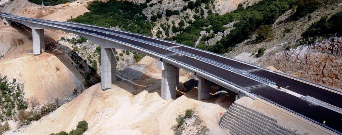
Infrastructures
Cast iron drainage solutions, particularly our ITINERO® range, are essential for infrastructure projects such as bridges and viaducts. These projects demand materials that can withstand extreme conditions and heavy loads, and our ITINERO® pipes are engineered to meet these rigorous requirements. Their exceptional strength and durability ensure long-lasting performance, reducing the need for frequent repairs and replacements. This reliability is crucial for maintaining the integrity and safety of critical infrastructure.
For engineering firms and construction companies, the benefits of Pam Building’s ITINERO® cast iron solutions are clear. The robust nature of cast iron provides superior resistance to environmental stressors, including temperature fluctuations and mechanical impacts. This makes ITINERO® pipes
Worldwide references
EUROPE
Central Greece Motorway E65 Bridges, Greece
Athens Metro - Athens, Greece
Mont Blanc Tunnel - Haute-Savoie, France
Tournon Viaduct - Savoie, France
Kula Vodno - Skopje, North Macedonia
ASIA
Gayrettepe - Istanbul Airport Metro - Istanbul, Turkey
Eurasia Tunnel - Istanbul, Turkey
MIDDLE-EAST
Doha Metro - Doha, Qatar
Step Project - Abu Dhabi, UA
AFRICA
TGV Train Station - Kenitra, Morocco
OCÉANIE
ideal for infrastructure projects that require materials capable of enduring harsh conditions while maintaining structural integrity over time.
Installers will appreciate the ease of installation and low maintenance requirements of our ITINERO drainage systems. The modular design allows for quick and efficient setup, minimizing disruptions to construction schedules and reducing labor costs. Additionally, the low maintenance needs of cast iron systems translate into significant cost savings over the lifecycle of the installation. By choosing Pam Building’s ITINERO® solutions, infrastructure projects can ensure a reliable, durable, and cost-effective drainage system that meets the highest standards of performance and safety.
Dumbea Bridge - Noumea, New Caledonia
Cross Yarra Rail Tunnel - Melbourne, Australia
Dumbea Bridge
Technical Support
Design studies
We help our customers define the most optimised network for epams®, ITINERO® or ELIXAIR® systems, our technical support team designs solutions and provides drawings and bills of quantities.
Rainwater on flat roofs project epams®
Send us:
→ Your drawings in DWG format (roof, levels, section views, etc.)
→ The general rainfall intensity of your country (in mm/hr or l/s.m).
You will receive a response concerning the feasibility and an initial design study*.
*Full studies are conditional upon the final order of the materials.
Bridges & tunnels projects ITINERO®
Send us:
→ The drawing of the bridge
→ The drainage location (outlet and collector) in DWG format. We will provide you with:
• A design recommendation
• The discharge system’s set-up
• A bill of quantities.
We will support you with the system’s complete design.
Heat exchanger project ELIXAIR®
Send us your project and we will be able to help you with the supply of:
→ Your earth-to-air heat exchanger
→ The bill of quantities
→ The heat energy saved in winter
→ The cooling energy saved in summer.
Estimate your project
Send us the drawing of the discharge system’s location with details of the pipe diameters in the following formats: DWG (preferred), RVT or PDF.
Based on general plumbing rules, we will provide you with the general bill of quantities including the numbers of the parts, and the references to order.
Our service portfolio is fully aligned with the new expectations of MEP consultants and contractors working on safe, comfortable and durable building projects.
In addition to our recommendations in this catalog, if you have any questions, you can ask our experts on the following topics:
→ Acoustics
→ Fire protection
→ Technical and functional advice (see “Design & Recommendations” section)
→ Environmental building certifications
Upon request, Pam Building can provide special designs of fittings outside the ranges offered in our catalog*.
Send us your details and we will provide a response concerning the feasibility within two days.
The latest example is the 125 x 100 x 100 mm Double Branch, which is now available in our product range.
*Sales to order only
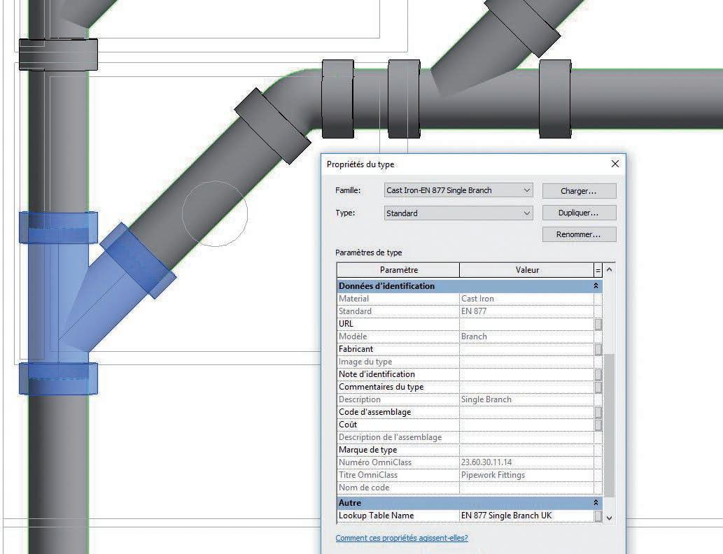
Pam Building aims to ease the burden on developers, specifiers and contractors in the early stages of construction by providing two levels of BIM library and supporting information.
The new releases include a full-data objects library, a platform that provides supporting information and free individual BIM files for all products and systems.
These include an EN 877 “Generic Cast Iron” content package for use in the early design stages, with parametric model fittings, and standard geometric settings. The files contain only the most vital information, reducing the time and effort required to create early stage plans. These “datalight” designs can also be overwritten with the full data specification libraries without issue, speeding up later stages of development that require more detailed plans, streamlining the transition from design to as-built work flow.
Pam Building Libraries are designed to aid data transmission between the consultants and the Main Contract MEP design engineers, creating a leaner process that reduces design time.
By providing small file sizes for the generic content, it will facilitate early stage specification in BIM and speed up the whole planning process; this in turn will create measurable cost and time savings for our customers.
Pam Building has been developing BIM Level 2 libraries in Revit for its domestic use (S), siphonic rainwater (epams®) and intensive use (Plus) ranges.
→ New registration required to keep up to date with new/revised content → Full parametric pipe systemps generic and full data
→ All fittings have constrained couplings which can be turned on/off
→ No ‘manufacturer’ data
→ All files are light at 500 KB max
PAM CAST IRON LIBRARY
Full data content
→ Minor modifications to project design stages
→ Time saving design for main contract BIM Engineers
Customer services
We
sell products all
over the world
We provide logistics services
Our customer service teams will be happy to help!
With 150 years of experience in worldwide export sales, our international organization obtains all our customers’ feedback which we need to help us constantly improve our products and services.
Every day, Pam Building ships a wide range of products to provide its customers with complete, operational solutions wherever they are.
Depending on your needs and practices, you can either manage the transport yourself or we can quote you in accordance with the Incoterms you wish to contract with us.
To speed up the process, we have signed an agreement with French Customs.
To optimize its customer service, Pam Building has an integrated network of subsidiaries, agents and distributors which can rely on dynamic and experienced technical sales teams to provide excellent customer support.
We develop and produce complete cast iron drainage systems
Domestic Use S range
The standard range for the transportation of fluid waste and rainwater through buildings.
Recommended use
Domestic effluents: grey water, black water and rainwater
→ Commercial, public and residential buildings, particularly medium- to high-rise buildings which require robust and safe solutions for basements and lower levels to vertical risers: Offices, shopping centers, housing, airports, hotels, public builidings, stadiums
Certified performance
→ Compliant with standard EN 877
→ Guaranteed performances by quality marks delivered by third party
Easy maintenance & installation
→ Ease of installation due to the mechanical couplings assembled with simple tools
→ Adaptable to all configurations with available accessories connecting cast iron with other materials
→ Limited maintenance operations thanks to the technical and mechanical properties of cast iron.
Fire safety
→ Reaction to fire: Euroclass A1
→ Fire resistance: up to 240minutes depending on the configuration (generally requires no special fire protection saving time and costs)
Chemical & corrosion resistance
→ Hot water resistance: 24 h at 95°C
→ Thermal cycle resistance: 1,500 cycles between 15°C and 93°C
→ Chemical resistance for 2 ≤ pH ≤ 12
Acoustic comfort
→ Lsc,A < 10 dB (A) according to EN 14366 with flow rate of 2l/s
Environment
→ Recycled content: 99%
→ Fully recyclable
• External coating: Red-brown, acrylic primer paint, average dry film thickness 40 μm.
• Internal coating Two-component ochre-coloured epoxy coating, average dry film thickness of 130 μm.
• Cast iron made with the De Lavaud process
Domestic Use
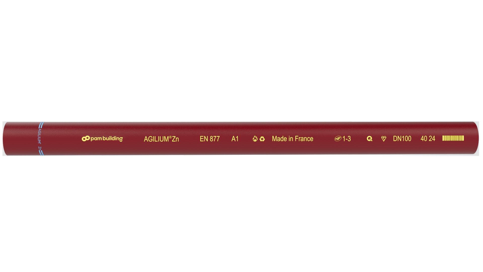
AGILIUM®
Pam Building launches a new drainage solution that reduces its environmental impact and facilitates the daily work of installers. An innovation that is part of our eco-design approach.
Recommended
use
Domestic use: Wastewater, rainwater, runoff water, hot effluents
→ Commercial, public and residential buildings, particularly medium- to high-rise buildings which require robust and safe solutions for basements and lower levels to vertical risers: Offices, shopping centers, housing, airports, hotels, public builidings, stadiums
Certified performance
→ Compliant with standard EN 877
→ Guaranteed performances by quality marks delivered by third party
Easy maintenance & installation
30% weight reduction of the pipes and 15% for the fittings compared to standard range: a 3m Agilium® DN100 pipe weighs just 17 kg, compared to 24 kg for the standard range.
Due to their exceptional mechanical properties, cast iron drainage systems prevent the worry of untimely and costly repairs.
Possibility to:
→ Mix Agilium® pipes with fitting
→ Mix pipes of the standard range with Agilium® fittings
→ Use most standard joints
→ Keep most of the reservations for standard range with Agilium®
Fire safety
→ Reaction to fire: Euroclass A1
30% LIGHTER
Vs our standard range
→ Fire resistance: up to 240 minutes depending on the configuration (generally requires no special fire protection saving time and costs)
Acoustic comfort
→ Lsc ≤ 13 dB(A) & LaA = 46 dB(A) according to EN 14366 with flow rate of 2l/s
Environment
Agilium® is our first eco-design, in line with our environmental roadmap. Our solution is made from recycled materials and is fully recyclable.
The plumbing package represents less than 5% of a building’s C02 emissions (data from life cycle analysis), according to a sensitivity study conducted in France by the Bastide Bondoux, Pouget and Tribu design offices, on a 4-story office building (4,000 m2).
AGILIUM®
30% lighter than standard pipes
20% less co2
99% recycled material & fully recyclable FOR PLUMBERS
→ Easier to carry with a weight reduction of 30%
→ Faster to install with less time spent on pipe handling
FOR DESIGN OFFICES
→ More agility with a space-saving in increasingly more constrained spaces
FOR PROJECT OWNERS
→ Better environmental compliance with a 20% reduction in carbon emissions
Less CO2 emissions compared to our current ranges
This performance is validated by comparing our new Agilium® Environmental Product Declaration (EPD) with the one previously available on the environdec database (www.environdec.com).
Pipes / S range & Agilium®
Bends / Short radius bends
Bends / Short radius bends
Bends / Short radius bends
Bends / Long radius bends
Bends / Long tail bends
Bends / Double bends
Bends / Long tail double bends
Bends / Offsets
Bends / Vented bends
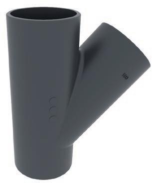
Branches / Long tail single branches
Branches / Long tail double branches
Hatch patterned area in the drawings shows the max. cutting length
Hatch patterned area in the drawings shows the
Branches / Short corner
Branches / Long tail corner branches
Branches / Single long arm branches
Tappered pipes / Reducers
Access Fittings / Access pipes
Access Fittings / Blanck ends
Access Fittings / Expansion plugs
See p.132 for information on resistance to accidental pressure. Expansion plugs with bleeding valve are available on request for DN 125/DN 150 and DN 200 (for watertightness tests)
Traps and ventilation / Traps
Bottom cleaning access: EP by expansion plug / TS by tight sheet Designed for rainwater networks. The arrows stamped on the cast iron body show the flow direction.
Hatch patterned area in the drawings shows the max. cutting length.
Traps and ventilation / Anti-syphon traps with side access door*
*With brass closing Suitable for all wastewater drainage systems, the Anti-Syphon Trap is particularly well-suited to systems without secondary ventilation. It ensures the retention of a water seal within the body of the trap to prevent odors traveling backwards through the system and fouling the atmosphere around sinks, washbasins, baths, rainwater outlets, etc. The Anti-Syphon Trap works by preventing the siphoning effect of a heavy discharge through the system. It does this through the internal partition within the trap allowing the air to bypass the water, thus breaking the vacuum created by the discharge water.
Traps and ventilation / Vertical vented traps
The vertical outlet version consists of 3 x product code: 155813 and 1 x product code: 156585. The horizontal outlet consists of 1 x product code: 156585 and 2 x product code: 155813.
Traps and ventilation / Roof penetrators
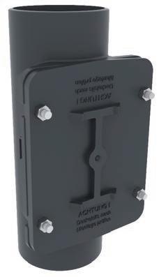
Stack support
03. Product catalog Domestic use
Stack support / Pipe
Stack support / Bracket
Special fittings / Manifold connector
The multi-waste manifold simplifies waste plumbing by grouping all associated pipework from various sources such as sinks, basins, bidets, urinals and showers to one internal point above the finished floor level. See p.150 for installation details.
Special fittings / Single stack branch
Branches for single downpipe with 2 to 3 inlets - combined networks
Special fittings / Flanges
Connector with PN10 flange
Intensive use
Plus range
High-performance solution designed to withstand intensive use.
Recommended use
→ Above- and below-ground applications when exposed to hot and/or aggressive discharge. When installed below ground in aggressive environments it is highly resistant to external stresses.
→ Hospitals, laboratories and collective kitchens
Certified performance
→ Compliant with standard EN 877
→ Guaranteed performances by quality marks delivered by third party
Easy maintenance & installation
→ Long-lasting operational safety thanks to the robustness and stiffness (around 700 kN.m) of cast iron and the use of flexible mechanical couplings
→ Ease of installation due to mechanical couplings assembled with simple tools
Fire safety
→ Reaction to fire: Euroclass A2, s1-d0
→ Fire resistance up to 240 minutes depending on the configuration (generally requires no special fire protection,saving time and costs)
Chemical & corrosion resistance
→ Hot water resistance: 24 h at 95°C
→ Thermal cycle resistance: 1500 cycles between 15°C and 93°C
→ Chemical resistance for 2 ≤ pH ≤ 13: up to 80°C (check resistance for more than 30 different effluents in the tables on p.56 and 57)
→ External coating corrosion resistance test to neutral salt spray according to standard NFEN ISO 9227_2017: 2500 hours.
Acoustic comfort
→ Lsc,A < 10 dB (A) according to EN 14366 with flow rate of 2l/s
Environment
→ Recycled content: 99%
→ Fully recyclable
• External coating: Grey, acrylic primer paint, average dry film thickness of 40 μm.
• Anti-corrosive layer: zinc coating of 130 g/m2
• Cast iron: Made with the De Lavaud process
• Internal coating: Two-component ochrecoloured epoxy coating applied in two layers, average dry film thickness of 250 μm
Externally and internally coated with a grey powder
Bends / Short radius bends
Intensive
Bends
/ Short radius bends
Intensive use
Intensive use
Bends / Long tail single branches
Hatch patterned area in the drawings shows the max. cutting length
Hatch patterned area in the drawings shows the max. cutting length
Bends / Short double branches
Intensive use
Bends / Short corner branches
Bends / Single long arm branches
Bends / Tappered pipes
Access Fittings / Tappered pipes
Intensive use
Access Fittings / Blanck ends
Access Fittings / Expansion plugs
See p.132 for information on resistance to accidental pressure. Expansion plugs with bleeding valve are available on request for DN 125/DN 150 and DN 200 (for watertightness tests)
Traps and ventilation / Traps
Bottom cleaning access: EP by expansion plug / TS by tight sheet Designed for rainwater networks. The arrows stamped on the cast iron body show the flow direction.
Hatch patterned area in the drawings shows the max. cutting length
Intensive use
Intensive use AGILIUM® Zn range
High-performance solution designed to withstand external stresses due to climate exposures (ultraviolet radiation, saline mist, condensation, freezing-thawing cycles and pollution).
Recommended use
Domestic use: Wastewater, rainwater, runoff water, hot effluents
→ Coastal areas, directly or indirectly exposed to climatic stresses polluted or confined atmospheres (cellars, crawl spaces), exposition to external aggressions during manufacturing processes and condensation.
Certified performance
→ Compliant with standard EN 877
→ Guaranteed performances by quality marks delivered by third party
Easy maintenance & installation
→ Long-lasting operational safety thanks to the robustness and stiffness (around 700 kN.m) of cast iron and the use of flexible mechanical couplings
→ Ease of installation due to mechanical couplings assembled with simple tools
Coatings
Fittings: Externally and internally coated in red epoxy to an average thickness of 70 μm.
Fire safety
→ Reaction to fire: Euroclass A2, s1-d0
→ Fire resistance up to 240 minutes depending on the configuration (generally requires no special fire protection,saving time and cost
Chemical & corrosion resistance
→ Hot water resistance: 24 h at 95°C
→ Thermal cycle resistance: 1500 cycles between 15°C and 93°C
→ Chemical resistance for 2 ≤ pH ≤ 13: up to 80°C (check resistance for more than 30 different effluents in the tables on p.56 and 57)
→ External coating corrosion resistance test to neutral salt spray according to standard NFEN ISO 9227_2017: 2500 hours.
Acoustic comfort
Lsc,A < 10 dB (A) according to EN 14366 with flow rate of 2l/s
Environment
→ Recycled content: 99%
→ Fully recyclable
• External coating: Red-brown, acrylic primer paint, average dry film thickness 40 μm.
• Anti-corrosive layer: flame-applied zinc metal coating of 260 g/m2 on average
• Cast iron: Made with the De Lavaud process
• Internal coating: Two-component ochrecoloured epoxy coating, average dry film thickness of 130 μm.
AGILIUM® Zn range
All dimensions are in mm.
Pipes
AGILIUM® Zn SMU Zn
For dimensions over DN 300 please contact us.
For details of the fittings to be used with Agilium® Zn pipes, please contact us.
We have highperformance solutions for your most demanding projects.
Infrastructures ITINERO®
A solution that meets the high drainage technical demands of infrastructure projects, factors in the specificities of a project and guarantees excellent performance to accommodate different stress levels (weather onstraints or exposures).
Recommended use
Suitable for many bridge and tunnel designs and adapted to renovation projects
Collecting and draining surface water from bridges, tunnels and viaducts, for new builds or renovation projects.
Long lifetime with high resistance to climatic stresses due to the zinc coating and low thermal expansion coefficient of cast iron
Certified performance
→ Compliant with standard EN 877
→ Guaranteed performances by quality marks delivered by third party NF, GeG et Kitemark
Easy maintenance & installation
→ Low maintenance due to the best in class resistance to shocks and crushing
→ Easy to install due to mechanical couplings assembled with simple tools.
Chemical & corrosion resistance
→ Hot water resistance: 24 h at 95°C
→ Thermal cycle resistance: 1,500 cycles between 15°C and 93°C
→ Chemical resistance for 2 ≤ pH ≤ 12
→ External coating corrosion resistance test to neutral salt spray according to standard NF-EN ISO 9227_2017: 4500 hours.
• External coating: Grey (approximate RAL 7030), epoxy coating, average dry film thickness of 80 μm
• Anti-corrosive: zinc coating of 260 g/m2 (about 40 μm)
• Internal coating: epoxy coating, average dry film thickness of 130 μm.
• Cast iron: Made with the De Lavaud process
Externally and internally coated with a mat grey powder epoxy (approximate RAL 7030),
Access Fittings / Pipes
Access Fittings / Blank ends
Stack support
Rectangular
Rainwater drainage Gravity system
Residential (type R)
A solution that will give additional value to the buildings due to its round or fluted aesthetic appearance.
Certified performance
Compliant with standard EN 12056-3
Long lifetime with high resistance to climatic stresses due to the zinc coating and the low thermal expansion coefficient of cast iron
Shock resistance
The test consists of dropping a mass of 2.75 kg on a descent at increasing heights until it breaks or cracks.
The average height of the fall for residential (Type R) is 2 to 5 times higher than for other products. Up to an average drop height of 2m, the Residential (Type R) deforms while the other products have cracked.
Easy maintenance & installation
Crushing resistance
Low maintenance due to the best in class resistance to shocks and crushing Ease of installation due to the push-fi t assembly system.
• Anti-corrosive layer: flame-applied zinc metal coating of 130 g/m2 on average
• Internal coating: water-based coating of 40 μm.
• Cast iron: Made with the De Lavaud process
Cataphoresis 70 μm + water-based coating 60 μm.
Gravity Systems Residential (Type R)
Round downpipes / Straight
our Residential (Type R) downpipes and fittings are delivered with their couplings
Round downpipes / Bended
Fittings / Round downpipes bends
With socket Offsets / Round
Gravity Systems Residential (Type R)
Gargoyle / For roadsides (Profile A)
Gargoyle / For pavements (Profile T)
Gargoyle / Shoe to head connector
Siphonic roof drainage
The epams® siphonic roof drainage system is designed for the rapid evacuation of large volumes of water from flat roofs: gymnasiums, shopping centers, airports, and warehouses. Its high flow rate and fewer downpipes compared to conventional gravity systems make it ideal for buildings that require efficient and reliable water drainage solutions.
TWO TYPES OF OUTLETS
ACCESSORIES
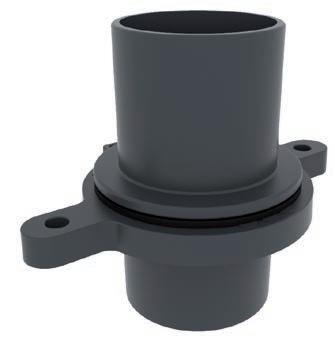
CAST IRON OUTLET
→ Suitable for all type of roofs
→ Ideal for car parks and high traffic environment.
Application field:
→ Concrete or metal roofs
→ Flat roofs with synthetic membranes
→ Metal gutters and valleys
→ Car park terraces
→ WITH STEEL PLATE
All flat roofs
→ FOR FLEXIBLE PVC MEMBRANE
Non accessible roofs and/or with equipment zones, and waterproofed by PVC-P membranes
→ WITH FLANGE
Extra thick metal gutters or valleys as well as roofs waterproofed by synthetic membranes.
Certified performance
→ EN 877: Cast iron pipes and fittings, their couplings and accessories for the evacuation of water from buildings.
→ Technical Assesment System under French Technical Approval epams® 5.2/14-2386_V2
STAINLESS STEEL OUTLET
→ Suitable for environments exposed to corrosion (sea, pollution, etc.).
→ Ideal for green roofs.
Application field:
→ Concrete or metal roofs
→ Flat roofs with synthetic membranes
→ Metal gutters and downspouts
→ Roofs protected by gravel or vegetation
→ TO BE WELDED
Gutters or metal roof valleys
→ GREEN ROOFS
Ensures efficient drainage and seamless integration with vegetated surfaces
Easy maintenance & installation
→ Reduced installation time and labor costs.
→ Reduced maintenance costs: The integrated grating and anti-vortex mechanism allow for quick removal and reassembly, facilitating easy intervention and maintenance.
STAINLESS STEEL
Outlets to be welded
Outlets with flange
Outlets with steel plate
Stainless steel body, including M10 bolts, Aluminum grating
*The advantage of the DN 125 outlet is in the “gutters” application where the water cover height can exceed 55 mm (see French Technical Approval 5.2/ 14-2386_V2) *This outlet is the basis for the next three outlets, on which various elements are grafted depending on the application field.
steel body, including M10 bolts, Aluminum grating,
*The advantage of the DN 125 outlet is in the “gutters” application where the water cover height can exceed 55 mm (see French Technical Approval 5.2/ 14-2386_V2) *This outlet is the basis for the next three outlets, on which various elements are grafted depending on the application field.
including M10
*The advantage of the DN 125 outlet is in the “gutters” application where the water cover height can exceed 55 mm (see French Technical Approval 5.2/ 14-2386_V2) *This outlet is the basis for the next three outlets, on which various elements are grafted depending on the application field.
Stainless steel roof drainage
Outlets for flexible pvc membranes
Stainless steel body, including M10 bolts, Aluminum grating Laminate-steel PVC plate - 500 x 500 mm
*The advantage of the DN 125 outlet is in the “gutters” application where the water cover height can exceed 55 mm (see French Technical Approval 5.2/ 14-2386_V2) *This outlet is the basis for the next three outlets, on which various elements are grafted depending on the application field.
Accessories / Elevating kits
Accessories / Anchoring steel plate
Accessories / Nuts & scews
Anchoring
INO PLUS
Cast iron roof drainage system for car parks
LOAD CLASS M 12,5T maximum loading
CLASS L 1,5T maximum loading
The correct outlet must be specified as installation requires.
Cast iron flat roof outlet DN75
*Please select the required accessories
→ With loose and fixed flange for clamping roofing membranes
→ Cast iron
→ Length: 400 mm
→ Connection pipe with scale can be shortened individually (if necessary, apply cut edge protection)
→ Nominal capacity: siphonic system (24 l / s)
Stainless steel roof drainage
top rings
Cast iron flat grates
Dust bin
M CLASS
→ For top ring and flat grating class M
L CLASS
Polyamide leaf collector
Gasket insert
213 | height 41 0,90 198351
→ For class L attachment ring and flat grating
→ Only for accessible roofs
→ Made of polyamide for collecting gravel and leaves
→ Also for inspection chambers
→ For flat roof drainage 2 gasket inserts are required per flange
INO PLUS
Stainless steel roof drainage
Green roofs and emergency
Elevating kit
Elevating kit - Adjustable height
Elevating kit
Also available in other heights or closed at the top
→ Stainless steel (material 1.4301)
→ Emergency attachment ring 60 mm (incl. seal)
→ For emergency drainage system
→ To be used with polyamide leaf trap
Also available in other heights or closed at the top
→ Stainless steel (material 1.4301)
→ Emergency attachment ring 60 mm (incl. seal)
→ For emergency drainage system
→ To be used with polyamide leaf trap
Emergency ring
Track heater
Also available in other heights or closed at the top
→ With seal
→ Stainless steel (material 1.4301)
→ For an emergency drainage system
Also
Coupling range Product Catalog
We provide a large range of couplings to match all building specifications. Our products are available in different versions to withstand all types of effluents, pressures and external stresses.
PAM R
PAM Rapid
“R” for Repair: this coupling is particularly suited to repairs and retrofi ts. It is installed in two separate parts.
Major benefits
→ Compliant with EN 877
→ Full opening strap particularly suited to renovation projects.
Material
→ Main material W5 (AISI 316L)
→ Gasket EPDM.
The single-bolt PAM Rapid coupling allows fast and reliable installation. It ensures optimized watertightness, pressure and corrosion resistance.
PAM HP Flex
PAM HP FLEX couplings withstand up to 10 bar of hydrostatic pressure for most diameters. These couplings are used for straight runs where the pressures can occur.
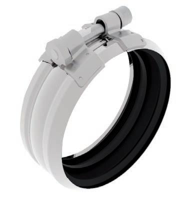
PAM HP Grip
Major benefits
→ Compliant with EN 877
→ Ease of installation
→ Suitable for projects with effluents containing solvents, hydrocarbons (i.e. car parks), due to the availability of the NBR version (nitrile gasket).
Pressure resistance
Exceeds the EN 877 requirements:
→ DN 50 to 125: 10 bar
→ DN 150 to 200: 5 bar.
Material
→ Main material W2 or W5 (AISI 316L)
→ Gasket EPDM or NBR.
Pressure resistance
Exceeds the EN 877 requirements:
→ DN 50 to 125: 10 bar
→ DN 150 to 200: 5 bar
→ DN 250 to 300: 3 bar.
Major benefits
→ Compliant with standard EN 877
→ The solution for large-diameter networks (>300 mm
Material
→ Main material: W4 (AISI 304) or W5 (AISI 316L)
→ Gasket: EPDM or NBR.
In sections where end thrust efforts have to be addressed, the autogrip couplings are alternative solutions for securing junctions whilst addressing pressure.
The PAM HP GRIP couplings are self-anchored couplings with built-in claw rings.
Major benefits
→ Compliant with standard EN 877
Pressure resistance
Exceeds the EN 877 requirements:
→ DN 100 to 400: 10 bar
→ DN 500 and DN 600: 6 bar.
→ The 2-in-1 solution: coupling and grip collar with only one product
→ Particularly suited to epams® installation.
Material
→ Main material: W4 (AISI 304) or W5 (AISI 316L)
→ Gasket: EPDM or NBR.
Pressure resistance
Exceeds the EN 877 requirements:
→ DN 100 to 400: 10 bar
→ DN 500 and DN 600: 6 bar.
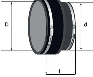
Coupling main features
A coupling is made of several components: casing, screws, barrel and gasket as described in the drawing.
*Please refer to datasheet for specific information as some material may differ depending on the coupling design. Screw and
Several grades of steel
We follow a global material designation* for steel components of the coupling described in the following table.
Couplings, Collars & Connectors
All dimensions are in mm.
Elastomeric gaskets
The choice of the elastomeric gasket is related to the nature of the effluent.
EPDM: EPDM rubber is suitable for most types of effluents.
NBR: Nitrile Butadiene Rubber is recommended for wastewater and runoff water liable to contain hot mineral oil, solvents or hydrocarbons. They are recommended for infrastructure applications.
→ Screw and nut: austenitic stainless steel A4-70 or AISI 316
PAM RAPID-S / PAM RAPID INOX
The PAM Rapid is designed for full tightening with “zero gap”, there is no need to check the torque. For DN 250 and 300, apply the following torque: 25 N.m.
PAM RAPID INOX with NBR gasket (Nitrile coupling)
For wastewater liable to contain hot oil, solvents or hydrocarbons, it is recommended to use couplings equipped with specific NBR gaskets.
versatile, the PAM grip collar is compatible with all the Pam Building designed couplings or those of equivalent
Couplings, Collars & Connectors
Connectors / Stepping rings
Connectors / Adapting collars
Connectors / Adapting collars and Stepping rings
Connectors / Adapting joints
Connectors / EPDM plugs
Connectors / PAM Konfix
* minimum / maximum external diameter of the pipes to be connected. All dimensions are in mm
Transitional connectors DN 50-125 are designed for connecting the cast iron S and Plus ranges to other materials, whether steel or plastic. The connections with these flexible connectors are easy and safe: one pre-cut lid and a lip seal inside (see figure). EPDM and hose clamp made of chrome steel no. 1.4016.
Couplings, Collars & Connectors
Connectors / PAM Konfix Multi
Connectors / PAM Multiquick
Multiquick connector
100x70
Earth-to-air exchanger
Recommended use
→ Public buildings
→ Commercial and industrial buildings
→ Farm buildings
Certified performance
System under French Technical Approval 14.5/14-2056_V1 CSTB
Environment
Energy savings thanks to the complete system and the high thermal conductivity of ductile iron
The ELIXAIR® system by Pam Building is an innovative earth-to-air heat exchanger (EAHX) designed to enhance thermal comfort in buildings.
By utilizing buried ductile iron pipes, ELIXAIR® efficiently warms fresh air in winter and cools it in summer, providing significant energy savings. Its robust construction ensures durability and resistance to ground and traffic loads, while maintaining excellent air tightness and indoor air quality.
ELIXAIR® is a sustainable solution that combines safety, efficiency, and long-lasting performance, making it ideal for various building types.
Major Benefits
→ Resistance to ground loading and traffic: ductile iron pipe systems can be buried deep without damage, also under areas which are driven over or car parks
→ Withstands rustic laying conditions allowing backfill with the extracted materials
→ Excellent air tightness due to High Pressure or Standard couplings working under compression
→ Durability: as for all buried systems, strength and long-lasting properties are key factors to avoiding premature replacements.
Send us your project and we will be able to help you with the supply of:
• Your earth-to-air heat exchanger
• The bill of quantities
• The heat energy saved in winter
• The cooling energy saved in summer
Supporting & Fixing systems
Brackets / 802 collars
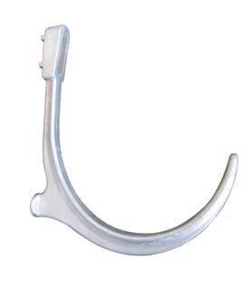
Brackets / Suspension hooks 101
Fixing settings
→ Ease of fixation thanks to a 4 cm opening in the upper part of the hook
Reduced bearing surface
→ Recesses to address wall roughness
Automatic set up
→ Level marking on the hook that represents the waterline
Brackets / Suspension hooks 401
Brackets / Rubber-lined steel
Acoustic dampener / PAM Acoustic
Supporting & Fixing systems
Cantilever arms / Reinforcement 41/82/2 LG 450 galvanised steel
Cantilever arms / Fixation bolts
Stack support fixing kit
Tools / Exact saw machine
Paints and protections / Touch-up paint
After any cutting operation, the pipe ends must be protected by applying EXTREM 1. EXTREM 1 is a ready-to-use quick drying touch-up paint that air dries in 15 minutes. It is easily applied with a brush (included in the paint bucket),
Paints and protections / Touch-up spray paint (400 ml)
→ Specification texts
→ Certifications
→ Catalogues
→ Brochures
→ Technical contents → & more…
CAST IRON SYSTEMS, AN OBVIOUS CHOICE
Cast iron systems, an obvious choice
Certified performances
Pam Building pipe systems comply with European standard EN 877 and all our products are third party certified.
The quality of product ranges is guaranteed by Quality Marks
One of the best materials when it comes to fire safety
Cast iron, a non-combustible material, has a melting point of over 1000°C. In most cases it requires no additional fire protection.
All our systems have been tested independently: our cast iron ranges received the Euroclass ranking A1 for our standard “S” range and A2-s1, d0 for the “Plus” range.
The best acoustic solution on the market
The nature and density of cast iron confers acoustic properties guaranteeing comfort in use. Less protection for acoustic insulation is needed due to its acoustic properties, resulting in plasterboard savings while achieving the same performance.
Durability, ease of installation, & less maintenance
→ Cast iron has a proven 70-year lifespan due to its outstanding mechanical properties and provides much better impact resistance
→ With our networks, maintenance operations are limited.
→ Compared to other materials, cast iron less embedment than other materials in buried applications where ground disturbance or extra loading is likely
Chemical & corrosion resistance
In addition to the requirements of standard EN 877, we have carried out a large panel of tests on commonly-used detergent products (floor cleaning products, laundry detergents, etc.) and special products (stain removers, drain cleaners, etc.): we have solutions to your most demanding projects.
Circular economy, an exceptionnal asset of cast iron
→ Our cast iron is manufactured entirely from recycled raw materials
→ We currently have produced and verified EPDs for our S and Plus ranges
→ The exceptional characteristics of our solutions allow them to contribute to HQE, BREEAM, LEED and other international environmental certifications...
The advantages of Cast Iron
Standard & Certifications
All our products comply with the European standard EN 877
The European standard EN 877 is applicable to a system (cast iron pipes and fittings, couplings and accessories for building drainage) and specifies the technical requirements for cast iron products, is the most stringent in the market.
In particular, it specifies requirements regarding:
→ Reaction to fire (product range)
→ Resistance to internal pressure
→ Dimensional tolerances
→ Tensile strength, crushing strength
→ Couplings and their leak tightness
→ Internal and external coatings performances.
It also defines test methods and the quality management system. Except for reaction to fire properties, EN 877 is a self-declared standard. The manufacturer is allowed to self-declare that their product complies with this standard. Only compliance with EN 877, which is validated by a third party for all criteria and periodically tested, can guarantee the performance of the systems you specify.
Quality marks
Pam Building cast iron drainage systems bear quality marksk certifying the compliance with EN 877 standard by third party.
→ Our system complies with all of the standard’s requirements
→ We are periodically audited by a third party
→ This gives you the ultimate quality guarantee.
Choosing a complete and consistent range of cast iron products, whose assembly has been performance tested against regulatory requirements, provides you with peace of mind that few other materials can guarantee.
The quality of product ranges is guaranteed by quality marks:
Cast iron pipes and fittings, their joints and accessories for the evacuation of water from buildings - (Requirements, test methods and quality assurance)
Elastomer seals - Material requirements
for a quality management system design, product development, production, installation and after-sales support
management system(Requirements with guidance for use)
management system
Testing standards
Fire tests
Fire classification of construction products and building elements. Part 1: Classification using data from reaction to fire tests
Fire classification of construction products and building elements. Part 2: Classification using data from fire resistance tests.
Reaction to fire tests for building products: Building products excluding floorings exposed to thermal attack by a single burning item
Measurement of noise
Laboratory measurement of noise from wastewater installations
13501-1
13501-2
13823
14366
CE Marking
The European Construction Products Regulation made CE marking mandatory on products for which the manufacturer has drawn up a declaration of performance.
The CE marking indicates that manufacturers take responsibility for the construction product’s conformity with the declared performance as well as compliance with all applicable requirements laid down in the European Construction Products Regulation.
→ To allow for free circulation of industrial products within the European Union and the European Economic Area
→ To guarantee that these products are not dangerous to European consumers and users
→ To have the same safety criteria shared throughout Europe
Fire safety was selected as the only essential requirement for the CE marking on wastewater products, which must be supported by laboratory tests conducted at recognized independent facilities. This led to a “Reaction to fire classification in the Euroclass system.
The CE marking is a self-declaration of product performance (DoP) in reference to its product standard (with the exception of reaction to fire which requires independent testing at a recognised fire testing center).
CE marking is not a quality mark nor a label
It certifies the compliance of the product with the harmonised part of the reference standards, and aims to harmonise rules for placing the product on the common european market.
Except for the reaction to fire class, the third-party certification of the performances is not guaranteed by EN 877, but by one of the following marks: Marque NF, RAL-GEG, Kitemark, Sintef, Gost, Q+, Watermark.
Product Marking: Pipes & Fittings
Company Logo Reaction to fire
Compliance with Standard EN 877 Pipe size
Product name
CE marking
Compliance with quality marks
Our fittings bear a marking and a label that identifies the manufacturing site
Fabrication date EAN code
Easy installation & reduced maintenance
Cast iron has a 70-year lifespan due to its outstanding mechanical properties and safety margin in operation.
→ Cast iron systems withstand cleaning operations, even at high pressure. They also withstand traditional unblocking chemicals and enzymes without damage: Pam Building is continuously carrying out research on its coatings to maintain such qualities.
→ Cast iron in exposed sections of the drainage system, i.e. basement car parks, is more resistant to damage than other rainage materials. It is also less sensitive to cracks and breakage prior to installation.
→ Cast iron below ground offers greater resistance to ground movement, and is less likely to fail in unfavorable conditions.
With our networks, maintenance operations are limited.
Cast iron drainage requires minimal maintenance during the lifetime of the building under normal conditions, making it the first choice for concealed, built-in or otherwise inaccessible systems, where repair or maintenance would cause major inconvenience to the occupants.
→ Where necessary, removable mechanical couplings make repairs easier and cheaper without cutting into the stack. An extensive range of access parts provides ease of maintenance at vital points in the stack to relieve any blockages which may occur.
→ In the event of destination changes in the premises or the addition of devices, the PAM systems, whose junctions are not glued or welded, can be modifi ed without having to break or cut them, by simply removing the joints.
The advantages of Cast Iron
Fire safety
Drainage systems are the arteries of a building. In case of fire, there is a risk that pipes will maintain and spread the fire in the building. Pipe penetrations through a separating element like a wall or a slab are always a source of risk for the spread of fire to the adjacent room, the floor below or the floor above. As regards a building’s fire safety, the major responsibility rests with the project manager who must comply with local regulations. Accordingly, and particularly in high-risk buildings like high-rise buildings,
Reaction to fire
EUROCLASSES
Classes other than E-d2 and F
Cast iron remains one of the best material when it comes to fire safety
materials with reduced flammability should be selected as a precautionary measure. Pam Building is committed to the development of high-quality and high-safety products. Fire safety is one of the main technical performances of our products. In choosing Pam Building cast iron systems, you are guaranteeing the safety of both people and property.
There are two concepts applied to fire safety: reaction to fire and fire resistance.
This is the instant behavior when a fire breaks out, its propensity to ignite or fuel a fire. This behavior is assessed on the basis of standardized tests and described in a Euroclass classification. The Euroclasses are based on test methods and establish reaction to fire classifications that are harmonised throughout Europe. This means they can be used to compare materials and product performances.
The Euroclass classification ranges from A1 to F, with A1 and A2 being reserved for products that are not, or are only slightly, combustible. The indices s and d respectively refer to smoke emission and the production of flaming droplets.
SMOKE production sub-classification
s1: Low smoke production
s2: Medium smoke production
s3: High smoke production
FLAMING DROPLETS sub-classification
d0: No flaming droplets
d1: Flaming droplets that persist for less than 10 s
d2: Flaming droplets
Scope
The CE marking for cast iron wastewater systems is based on the harmonised standard EN 877, which applies to a system including pipes, fittings, couplings and accessories, and is used to test all of the ranges’ components. The classification obtained by Pam Building covers complete ranges: pipes, fittings, couplings and accessories that are components of a wastewater pipe system.
Pam Building cast iron systems are among the safest materials on the market in terms of reaction to fire, and all its drainage systems have been tested independently to the stipulated test criteria.
In tests carried out by the CSTB accredited laboratory, the Pam Building cast iron ranges (pipes, fittings and accessories, including elastomer gaskets and coatings) received the following excellent Euroclass ranking:
→ A1 for the S range: completely non combustible
→ A2-s1,d0 for Plus range: No smoke, no flaming droplets in the event of a fire
Check the reaction to fire classification of the products you specify, and ensure the tests were carried out by an accredited testing centre. This compliance is validated by complete quality marks, is periodically tested by accredited third-party laboratories and provides you with a performance guarantee for the systems you specify.
Fire resistance
Main causes of fire
Faults in electrical systems, human error, overheating, and arson. Lightning strikes or explosions play a minor role in the statistics here, but can lead to a chain reaction of fires if they do occur.
Source: www.ifs-ev.org
Compartmental principle
Wastewater drainage systems & fire stopping requirements
This is a construction component’s ability to withstand fire for a given period of time and to retain its serviceability in the event of fire, avoiding the spread of fire. If a fire breaks out, it is essential to prevent any early collapse of the structure, and then limit the extent of the damage to ensure that occupants can be evacuated and/ or belongings will be protected. Many buildings are not sufficiently protected against fire hazards. This means that fire can spread quickly, destroy the building in a short time and, more importantly, endanger the lives of the occupants. When a fire breaks out, the first objective is to slow down its spread both horizontally and vertically. The fire resistance performance level will be influenced by a number of factors: the pipe diameter, the thickness of the floor or wall, the size of the penetration void, the material used to seal the void and even the stack configuration through the penetration.
When they exist, fire safety regulations for buildings are based on a compartmental principle. Within a building, a compartment is a fire rated space designed to stop the fire for a given period of time. The fire stopping requirement for walls (shells and slabs) is generally 2 hours or less - and exceptionally 4 hours. The requirement depends on the type of building and its level of occupancy, and can be very different from one country to the next.
Drainage systems passing through structures designed to withstand fire should not provide open breaches. For a given time, specified in the applicable regulations, they should not allow the passage of fire, smoke, heat or combustion products from one compartment another. Cast iron, a non-combustible material, has a melting point of over 1000°C. In most cases it requires no additional fire protection. Pam Building has and will continue to periodically test its cast iron drainage systems with standard mortar penetrations and other solutions in order to understand the potential effects of fire on its integrity, resistance
Comparison with other materials
For plastics, the fire stopping rule consists in “plugging the hole”. This function is achieved by using fire collars recommended by the manufacturers. Plastic materials, which are highly sensitive to heat, will not withstand fire, and will not remain in place, even in the case of a contained fire. As shown by laboratory tests in Germany, if the fire collars are not activated, particularly when installed under the fire compartment, they significantly increase the risk of the fire spreading downwards in a multi-storey building.
and overall performance. We carried out a non-exhaustive series of tests to offer precise guidance for fire resistance. Our systems proved to meet integrity and insulation requirements up to 240 minutes (4 hours)*, and should therefore not collapse causing potential danger to evacuating people or firefighters. Any questions ? Our technical team can provide guidance, help you select the right configuration for optimal performance, and provide you with a comprehensive report.
Contact our technical support team on our website: www.pambuilding.com
When some types of plastic material (e.g. HDPE and polypropylene) are exposed to fire they generate molten droplets, which could potentially spread a fire down through the building. Exposed to fire, plastic material releases toxic fumes and gases, which beyond a certain amount may be fatal to the people inhaling them.
* Furnace tests carried out in 2017-2018 according to EN 1366-3 at the EFECTIS testing centre, the European leader in fire
The advantages of Cast Iron
Acoustic comfort
What is noise from pipe systems ?
Noise in buildings is considered to be detrimental to health and quality of life. Efforts have been made in the last 30 years to attenuate the sounds coming from the street, worsening the perception of sounds emitted within buildings. Heat insulation policies aimed at reducing energy consumption will also heighten these perceptions. Among the priority criteria in the comparative performances of drainage materials, acoustic performance is considered to be second only to fi re safety: cast iron pipe systems have intrinsic acoustic properties. Owing to the development of equipment accessories, they offer outstanding performances.
Noise from wastewater pipe systems is classified in the regulation under “equipment noise”. Noise originating from pipe systems is due to the sound energy produced by water/ air turbulence, but mostly by the mechanical effect of the water flow on the internal pipe walls. In such circumstances a pipe will radiate noise outward and transfer it to any lightweight ceilings, cupboards and similar areas wherever it makes contact. Noise is an energy that affects air pressure and is transmitted through vibration. Sound is measured in decibels (dB) using a nonlinear scale. For equipment noise, the following categories are identified and measured:
Airborne noise
Airborne noise are vibrations that are propagated. In the case of wastewater pipe systems, this noise is mainly heard in the room where the pipe is located. When a material is dense and thick, the pipe walls prevent air-borne noise transmission
Structure-borne noise
The vibration of a building’s structure. It will be noticed in rooms adjacent to the pipe. When the noise produced in a pipe is not transmitted by the air, the residual noise is transmitted by structural vibrations. Whilst the mass of the cast iron limits the vibratory level, the junctions and fixings to the building will propagate noise. Objective: dampen the vibrations at the connections to the solid structure. Statutory requirements for “equipment noise” for structure-borne noise differentiate between noisy rooms and quiet rooms with sound attenuation requirements.
*generally living rooms, resting rooms and work rooms, the noise level requirements are generally around 30 dB, in cases where noise regulations exist.
Test results
Complete reports are available on request. Sound levels below 10 dB(A) are not mentioned in the test report.
Structure borne noise & PAM’Acoustic
For the requirements of extreme acoustic comfort (luxury buildings, auditoriums...), PAM’Acoustic is an acoustic dampener, which, placed between the frame and the support collar of the cast iron pipe, makes it possible to achieve the exceptional structural noise level of < 10 dB (A), that is, almost silence.
Tests according to standard EN 14366 (IBP laboratory). For a flow rate of 2 liters/second, wall: 220kg/m2
The advantages of Cast Iron
Noise in real condition of use
Usually pipe systems are installed in a technical shaft that contributes to reducing the noise emitted by the effluent flowing in a pipe. Nevertheless, the noise level of pipes installed behind a shaft may not be sufficient to comply with the specifications of the owner or set by the national regulation.
Pam Building initiated several noise measurement tests with an independent laboratory in real conditions, inspired by standard EN 14366, but using a real WC flush to assess the noise level of the combination of pipe material and shaft acoustic performance (ΔLan).
Below are some examples of measurements at a flow rate of 2 l/s with the S range fixed on a 15 cm thick supporting concrete wall:
Comparative laboratory tests
Acoustic comfort is a differentiation criterion that indicates construction quality. The building project manager and specifier may define together specific requirements to improve the final construction.
In 2019, Pam Building commissioned a series of comparative tests on airborne and structure-borne noises in installation conditions described by standard EN 14366*, at the Fraunhofer Institute for Building Physics in Stuttgart.
The measurement results for the Pam Building cast iron pipes listed in the table were determined at the Institute on an installation wall with a basis weight of 220 kg/m2
The prerequisites:
→ The building conditions in the real construction situation be comparable to or more favorable than the test bench of the Institute in terms of sound technology.
→ When compared with the requirements, pay attention to the simultaneous operation of plumbing installations and possible interactions among the plumbing components which may produce different results.
→ As a comparison value with the requirements, the measured value should be obtained at a flow rate of 2.0 l/s, corresponding approximately to one toilet flush.
→ The sound measurements were taken both on the opposite side of the installation (in the picture on the right) and in the mounting room (on the left of the picture).
*As all wastewater pipe systems manufacturers apply the standard test protocol, it allows building project managers to compare their results.
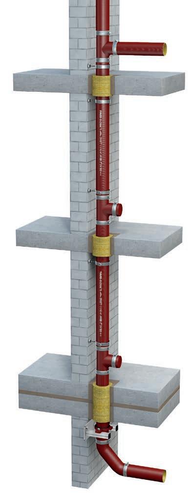
Technical Shaft
S range with rubber lined steel brackets S range with steel brackets and acoustic dampener
Details of the test configuration:
→ Standard bracketing: 2 bracket collars per floor. Both mounted with a 1 Nm torque.
→ Stack support: Stack supports are fixed to the wall/floor.
→ PAM’Acoustic: 2 anti-vibration brackets per floor. Both mounted with a 1 Nm torque.
Choosing our systems guarantees the best acoustic solution on the market
→ High basis weight
→ Low tendency to vibrate
→ Effective sound decoupling
→ High insulation value
→ Suitable for all pressures
→ Sewage installations
→ Precise installation instructions
→ Compliance with project specifications or regulations
DG: Attic
EG: Ground floor
front
The advantages of Cast Iron
Durability
Robustness & mechanical strength
Pipe system components must withstand hazards before they reach the job site such as accidental impact before and during installation, during storage, handling and transit. In service, outdoor exposed pipes may be damaged by accidental impacts or vandalism. To avoid breakages, which can be expensive, or minor stress cracks which can have serious consequences in operation, the choice of material should be carefully considered.
Impact strength and crush resistance
Compared with other materials, cast iron provides much better impact resistance and is highly recommended everywhere pipes may be exposed to mechanical shock (car parks, streets, etc.). Cast iron is well known for its robustness. The quality of Pam Building products is ensured by careful control of both the metal composition and the manufacturing process. The spinning of pipes in the De Lavaud process, followed by heat treatment, gives these products outstanding mechanical properties:
→ Mechanical characteristics superior to the requirements of EN 877*
→ Very good resistance to crushing
→ Increased impact resistance
→ The pipe is more resistant to mechanical stress such as bending and compression
→ For installers: installation is more comfortable and on-site handling is facilitated. Cutting pipes is easier, the slices are sharp. The set-up is therefore simpler and faster.
Pipes
These results indicate greater resistance to impacts and crushing, easier machining and cutting. This also means the products are easier to install on job sites.
*Key mechanical characteristics required by standard EN 877 are checked by three tests, carried out on pipes when coming out of the heat treatment furnace to assess tensile strength, ring crush resistance and hardness. In addition, operators have opted to perform a further test which provides a good indication of the heat treatment quality: impact test.
The De Lavaud process
In this process, a constant flow of molten metal at a perfectly controlled temperature and composition is gradually put into a steel mould rotating at high speed. The mould’s external wall is cooled by circulating water and the evenly distributed molten metal cools on contact with the wall before extraction. The process is characterized by quick cooling which gives a finer solidification matrix and thus a more homogeneous metallurgical structure. The spun pipes are placed and rotated in a heat treatment furnace at 950°C and then gradually cooled again. This step is essential to the process as it transforms the cast iron’s metallurgical structure. The reduction in iron carbides and the increase in ferrite content considerably improve the mechanical properties of cast iron and reduce its surface hardness. The graphite of the cast iron resulting from the Pam Building process forms clustered graphite, halfway between lamellar and ductile iron.
Stability to thermal variations
Cast iron pipes, thanks to their low thermal expansion coefficient, do not require specific devices to manage temperature variations, thus simplifying design and reducing installation costs.
Most solids expand when heated and are liable to elongate under temperature increases. For pipe systems made of materials that are subjected to high levels of thermal expansion, precautions must be taken at the design stage. Cast iron, which expands very little, does not require specific bracketing or expansion collars. It makes the specifiers’ design work easier and avoids extra costs at the installation stage.
Thermal expansion coefficient of cast iron and other materials
The thermal expansion coefficient for cast iron – 0.01 mm/m. °C – is very low and very similar to that of steel and concrete; the building and pipe systems will move and expand together.
Thermal expansion of cast iron and other materials for a temperature rise of 50°C and 10 m
Thermal expansion cœfficient
For cast iron, the bracketing system is designed to only carry the weight of the pipe and its content, which makes the designers’ work easier. Plastic pipes, however, expand considerably with increasing temperature. Their bracketing system must be designed and adapted accordingly, as it can significantly affect the pipework’s stability and performance over time.
Thermal expansion of plastics
To allow expansion without damaging the drainage network, plastic pipe systems require specific accessories – expansion collars or joints, brackets allowing axial movement, in general one of the two.
If these precautions were not taken, expansion could be absorbed by the pipework and cause distortion.
Cast iron does not require these expensive accessories. It makes the design work easier and decreases the risk of mistakes at the installation stage. These properties of cast iron pipe systems are also valuable for engineering structures such as bridges, where significant expansions have to be carefully addressed to secure the construction project.
The advantages of Cast Iron
Watertightness
Sanitary drainage systems, whether exposed or not, must remain watertight over time. Any defects can cause serious damage, leaks, dripping or slow permeation and generate costly repairs, and disruption. Pam Building cast iron mechanical assemblies are designed to easily achieve instant watertightness and are not dependent on process control (gluing or welding, etc.).
Watertightness of cast iron systems
Cast iron is a dense and non-porous material. Our systems are watertight and impervious. Straight and rigid cast iron components are assembled using metal couplings fitted with elastomer gaskets which ensure the system is completely watertight. Assemblies benefit from a conventional approach. Put together with only simple tools, they allow installation tolerance with no risk of leaks. This ease of installation ensures the specified performance is always obtained, even in adverse conditions, unlike with plastics when either gluing or welding can be affected by installation hazards (ambient conditions such as temperature or damp), or when personnel with special skills are required.
Watertightness over time
Failure of watertightness can occur on drainage systems in operation due to breaks, misalignments, crushes or cracks. Long-lasting watertightness depends on two main factors:
→ No deterioration of pipes: Cast iron is highly resistant to ovality. Their specified mechanical properties and stability enable cast iron systems to withstand operating stresses extremely well.
→ No deterioration of assemblies: Elastomers are carefully selected for the long-term stability of their physico-chemical characteristics to ensure the lasting watertightness of the rubber gaskets.
Watertightness and maintenance
Blockages can sometimes occur in drainage networks, therefore the pipework materials must be resistant so that maintenance is easy. The S and Plus systems can withstand all normal maintenance processes, including high-pressure jetting, without being damaged. They have undergone a high-pressure test according to Swiss standard SN 592 012. The robustness and dimensional stability of cast iron components along with the careful selection of elastomer ensure pipe installations are high-performance and have a long service life.
Cast iron pipes provide durable watertightness and are easy to install without special skills
Internal pressure resistance
Internal pressure in drainage networks rarely occurs and is always accidental. Thrust efforts in the overloaded sections have to be addressed to guarantee both watertightness and mechanical stability. As the robust cast iron components can withstand any pressure hazard, the couplings will be subjected to the strain. The quality of the couplings and their careful selection according to their field of use will prevent misalignment or disconnection of the pipework.
Resistance of the couplings to hydrostatic pressure
Standard pressure mechanical couplings
Wastewater drainage systems – which differ from rainwater drainage systems as regards pressure – are connected to sanitary appliances installed on each storey which may serve as outlets in case of accidental overloading (due to blockages, for example). The pressures that occur cannot therefore exceed the pressure corresponding to the height of one storey, i.e. about 0.3 bar. The couplings we describe as” standard” are perfectly suitable for this common type of application.
High-pressure mechanical couplings
In some rare cases, a wastewater drainage system may pass through a number of stories without any outlet, and there could be a risk of overloading blockage due to operation or saturation of the main sewer). The pressure resistance required to ensure these systems remain leaktight and stable in such cases depends on the height of the water column liable to occur, and in some cases calls for highpressure couplings able to withstand the resulting pressure (up to 10 bar).
Resistance to end thrust efforts
Some specific points on a pipe system may be subjected to thrust loads due to changes of direction and gradient, branches and plugs. To avoid any risk of disconnection or slippage of the pipe components, these loads must be addressed and the sections at risk must be anchored:
→ A straight section of pipes may be held between two fixed points with ductile iron brackets for example
→ Alternatively, a selfanchoring coupling or an ordinary coupling anchored with a grip collar can be used
Do you help determining the choices for your project ? Contact our technical support team on: www.pambuilding.com
The advantages of Cast Iron
Ageing behavior
The properties of cast iron ensure the stability of the systems and long-lasting operational safety.
As components that are integrated in buildings, wastewater and rainwater drainage systems must remain in a serviceable condition over the long term despite adverse operating conditions. Ageing refers to any gradual, irreversible change in a material’s structure and/ or composition, liable to a ect its behavior or serviceability. When a material is selected, the stability of its properties ensures operational reliability over time.
Stability of cast iron mechanical properties
The ageing of a material may be due to its own instability, environmental or chemical stresses, mechanical strains, or a combination of any of those causes. It is an established fact that cast iron offers long service, owing in particular to the stability of its mechanical properties over time.
Cast iron is not sensitive to thermal ageing
→ Its mechanical strength remains stable.
→ Its thermal expansion is very low compared to plastic.
→ Cast iron pipe systems are not liable to creep at operating temperatures.
Cast iron does not deform under mechanical strain
→ Its ring stiffness (cold measurement) around 700 kN/m is not affected by temperature and is 87 times that of PVC pipes. It is highly valued for buried pipework.
→ Its longitudinal stiffness, which facilitates bracketing and protects the water stream in horizontal sections, remains intact. Its Young’s modulus of elasticity is from 80 to 120 GPa vs 2 to 5 GPa for PVC.
→ Cast iron’s tensile strength is 8 times that of PVC: 200 MPa vs 25 (residual resistance, after 50 years according to the standards). This property is very important in case of network overloading
Resistance to climatic stresses
The properties of materials are extremely important when they are stored in or exposed to adverse conditions (extended exposure to ultraviolet light or wide-ranging temperature variations, etc.).
Cast iron undergoes no structural modification under climatic stresses.
Ageing of polymers
Deterioration of mechanical properties under temperature stress
Under the effect of temperature, plastics can suffer two kinds of deterioration, including at operating temperatures:
→ Creeping is an irreversible elongation under the combined action of both temperature and a significant mechanical strain. Plastic pipe systems like PVC or HDPE are particularly sensitive; in the horizontal sections, they can bend between two support brackets under their own weight.
→ Modification of the elastic limit: most plastic materials will soften when exposed to a temperature increase. With a decrease in temperature, however, they crystallise. PVC, for example, becomes rigid and may crack under mechanical strain – its operating temperature range is generally between -20°C and 80°C, but depending on its nature, the range can be much narrower.
Photochemical ageing
Depending on their nature, climatic stresses (such as solar radiation, damp or heat) will cause photochemical ageing to plastic materials of varying severity. They may merely alter their surface finish, or they may also deeply modify their mechanical properties and thus adversely affect their serviceability. The same can happen as a result of a slow chemical attack by solvents or even in an aqueous medium.
Chemical & corrosion resistance
Domestic use Characterisation of common domestic applications
Building wastewater drainage systems - grey and black water- must be able to withstand the types of domestic effluents specified by standard EN 877.
In recent years, however, changes have been observed in the types of these fluids:
→ Higher concentration of household detergents
→ Use of more aggressive hygiene products
→ Rise in operating temperatures.
The constraints on sanitary drainage systems are constantly increasing. To test chemical resistance of cast iron products, according to standard EN 877, the product samples are tested for 30 days at a temperature of 23 3°C with the following liquids (pH constantly monitored):
→ A solution of sulfuric acid with a pH of 2
→ A solution of sodium hydroxide with a pH of 12
→ A solution of wastewater with a pH of 7.
Resistance to hot water (24 h at a continuous 95°C) and thermal cycles (1,500 cycles of 5 min between 15°C and 93°C) are also tested according to standard EN 877. To provide clearer guidance on the chemical resistance of the S range in domestic applications, Pam Building has carried out 20 further tests in addition to the requirements of standard EN 877 on commonly-used detergent products (floor cleaning products, laundry detergents, etc.) and special products (stain removers, drain cleaners, etc.).
The additional tests also aimed to assess the S and Plus range limitations.
The tests were carried out on samples, under the temperature of use recommended by the manufacturers and, where relevant, up to 70°C since hot water is normally supplied in houses at around 50–60°C. After stopping the test, the pipes and fittings were washed immediately to eliminate any stains, and the coatings were examined for blistering and rusting according to ISO 4628-2 and 3. (Accepted levels according to EN 877).
The duration of the test is considered equivalent to the extrapolation of real chemical stress undergone for 7 or 10 years (10 to 15 min of stress per day).
This test method, however, simulates severe stress since the samples lie in direct contact with the solution, the temperature is maintained and the test includes no rinsing for its duration.
The advantages of Cast Iron
Cataphoresis: our industrial expertise to guarantee the best chemical resistance
Fittings and accessories are coated with an epoxy resin deposited by cataphoresis which ensures a uniform deposit and excellent covering of edges. Our industrial process is based on careful shotblasting and entails incorporating a chemical surface treatment during the coating cycle, between rinsing after shotblasting and the cataphoresis bath to enhance the coating’s covering power.
At the end of the cycle, the parts are oven dried to complete the reticulation of the epoxy film. Substantial improvements in the epoxy film’s adhesion to the cast iron and the corrosion resistance of the coated cast iron.
Recommended range for domestic use S range
According to the principle of continuity with no weak points, coatings for fittings and accessories must withstand the same stresses as pipes. There is an anti-corrosion coating process for these parts to ensure they can withstand major stresses, due to the fluids transported or the environment.
Intensive use
Internal stresses due to aggressive effluents
Characterisation of intense or professional uses
Aggressive effluents are characterized by their content (acids, bases, solvents, hydrocarbons, etc.), their combinations and their temperature. Above- and below-ground wastewater drainage for aggressive discharge are characterized by:
→ Hot water resistance: 24 h at a continuous 95°C and thermal cycles (1,500 cycles of 5 min between 15°C and 93°C)
→ Plus range external coating corrosion resistance test to neutral salt spray according to standard NF-EN ISO 9227_2017: 2500 hours
→ Chemical resistance: 1 < pH < 13
Characterisation of external stresses
Below-ground wastewater drainage systems exposed to environmental stresses. The buried section of a pipe may be laid in non-homogeneous ground or corrosive soil. When protected by galvanic effect, the pipework can be installed without requiring systematic soil studies. Buried systems are subjected to ground loadings which can cause shearing strain on couplings. For these applications, it is therefore recommended to the “all stainless steel version” of the steel couplings to avoid corrosion due to the aggressiveness of the ground.
Recommended range for intensive use Plus range
The limitation between the S and Plus ranges is only determined by the type of fluids and the operating temperature. However, the duration of daily exposure also directly determines the appropriate range to select, hence why we called this chapter intensive or professional use. The combination of high pH products (base and alkaline products) and high temperatures systematically calls for the use of the Plus range. With its anti-corrosion thick linings, the Plus range provides greater chemical resistance and is particularly well-suited to intensive uses.
→ To transport effluents containing acids, bases or saline solutions at common operating temperatures, systematic use of the Plus range equipped with couplings with EPDM gaskets is recommended.
→ For solvents, hot oil and where hydrocarbon traces may be present, the systematic use of the Plus range equipped with couplings with NBR gaskets is recommended.
The advantages of Cast Iron
Laundries
alkaline detergent designed for use in dishwashers
Acidic rinse specially designed for use on a wide range of dishwashers
Concentrated acid cleaner for descaling small equipment
Health care
disinfectant detergent for cleaning and disinfecting floors and surfaces
Détergent pré-désinfectant pour nettoyer les
Solvents (except acetone)
Intensive use: external stresses due to aggressive ground
Characterisation of external stresses
Below-ground wastewater drainage systems exposed to environmental stresses.
The buried section of a pipe may be laid in non-homogeneous ground or corrosive soil. When protected by galvanic effect, the pipework can be installed without requiring systematic soil studies.
Recommended range for these applications: Itinero® or Plus ranges
Buried systems are subjected to ground loadings which can cause shearing strain on couplings. For these applications, it is therefore recommended to the “all stainless steel version” of the steel couplings to avoid corrosion due to the aggressiveness of the ground.
Chemical & corrosion resistance
Intensive use: external stresses due to climate exposures
Outdoor or facade exposures
Depending on the climatic conditions, while in operation outdoor wastewater and rainwater systems can be subjected to ultraviolet radiation, saline mist, condensation, freezing-thawing cycles and pollution. The drainage systems must be fit for purpose despite exposure to adverse conditions.
Zinc coating improves the pipes’ ability to withstand climatic stresses and extends their service life.
What is Zinc coating ?
The zinc metal coating is an active protection provided by the galvanic action of a zinc-iron cell. This action is two-fold:
→ Formation of a stable protective layer of insoluble zinc salts
→ Self-repairing of any damage.
Zinc metalisation is an excellent corrosion inhibitor and is extremely effective at extending the lifespan of products subject to backfills or climatic stresses. the damage is worsened and the corrosion (red marks) extends beyond the notch
Recommended
for
From 99% waste recycled* to fully recyclable products
*Recycled content: proportion, by mass, of recycled material in a product or packaging. Only pre-consumer and postconsumer materials shall be considered recycled content.
For the standard S range, recycled content is 99% with 11.5% pre-consumer & 87.5% postconsumer according to ISO 14021: 1999.
Pre-consumer material: material diverted from the waste stream during a manufacturing process. This excludes the reuse of materials such as rework, regrind, or scrap generated in a process and capable of being reclaimed within the same process that generated it.
Post-consumer material: material generated by households or commercial, industrial and institutional facilities in their role as end users of the product which can no longer be used for its intended purpose.
The advantages of Cast Iron
Environment
Pam Building, a key player in the Circular Economy
The preservation of natural resources is a major societal challenge, especially for the construction sector, which is a major consumer of raw materials and energy. Pam Building evacuation systems are a responsible and sustainable choice, respectful of natural resources and people.
A cast iron pipe gives our waste a second life
In order to contribute to the preservation of natural resources, Pam Building’s molten iron is produced by recycling cast iron and ferrous products. Unlike plastics, it can be completely and systematically recycled at the end of its life.
Pam Building’s drainage solutions can be recycled without any deterioration of their properties.
The product’s life cycle is also first-class in terms of environmentallyfriendly logistics, longlasting functionality (up to 70 years without compromising the mechanical properties), low maintenance costs and commercially beneficial recycling
Nothing is wasted: everything is recycled
Cast iron pipe systems are based on the principle of modular ranges of removable components. Their mechanical assemblies are reversible. You can change your mind today or even tomorrow. When pipe systems are disassembled or modified, these components can be reused, which cuts down on waste dumping.
Organised and numerous actors in the recycling channel
The recycling channel exists: collector network and recovery stream is existing and working!
We work with local supply for scrap (<125 km from the plant) to reduced economic and transport costs.
Following ISO 14021:1999 and LEED V4 criteria we can provide a recycled content declaration for our products.
Life Cycle Assessment
A rigorous tool for assessing the environmental impacts of our products
Environmental Product Declaration
Understanding the environmental performances of construction products is a growing expectation for professionals in the building chain.
In Pam Building, we strongly believe that Life Cycle Assessment is the most reliable tool available to assess the green credentials of construction products and enables companies to communicate credible, fact-based information about their products to consumers. It is also a powerful tool for enhancing the environmental features of our products. LCA is a methodology based on specific standards ISO 14040 and ISO 14044:
→ Multi-criteria tool: consumption of natural resources, air, ground and water emissions, waste generation, warming potential…
→ Multi-step tool: “cradle to gate” or “cradle to grave”.
What is an Environmental Product Declaration?
The results of a LCA are presented in the form of an Environmental Product Declaration, locally administrated by program operators and based on ISO 25930 and EN 15804 standards. When an EPD has been checked by an independent third party, it is said to be verified. This process ensures the quality and reliability of the results: that is why we are committed to have verified EPDs.
We currently have produced and verified EPDs for our S and Plus ranges, both available on the Environdec platform: www.environdec.com
This table enables a quick and synthetic overview of environmental footprint of the functional unit (1 m of SMU S cast iron pipe system for collection and drainage of waste water, sewage and rainwater in buildings), based on 70 years of lifetime. The complete EPD is available on the international Environdec platform, registration number S-P-02013.