For more information on products, please use our Product Finder at products.spinner-group.com
You can get the latest new edition of our Test and Measurement catalogue in the download section of our website. Please follow this link: www.spinner-group.com/downloads
The specifications given here as well as the illustrations are for information. They shall only be confirmed by SPINNER‘s written offer and are subject to technical amendments.
Today any development, production, test or quality assurance department that works with RF signals on coaxial lines cannot function without latest measurement equipment. In high frequency technology vector network analyzers (VNA) are often used to determine the characteristics of RF and microwave devices.
The components of a VNA as well as the test assembly connected to the instrument have their own frequency and phase responses. This may cause false readings.
System errors can be adjusted by calibration of the VNA. During the calibration procedure, different calibration standards with defined and known electrical characteristics are connected to a VNA. These values and the measured values are compared to identify error coefficients. In a system error correction procedure the VNA adjusts the measured data of the DUT by the error coefficients. Thus the measurement accuracy increases.
The calibration of a VNA can be done in different ways depending on the required measurement accuracy. The calibration methods differ both in the number and form of the calibration standards used for the procedure.
The most commonly used calibration method is OSL (Open, Short, Load) for 1-port measurements and OSLT (Open, Short, Load, Through) for multiple port measurements.
The names OSL and OSLT for the calibration methods can vary with other manufacturers.
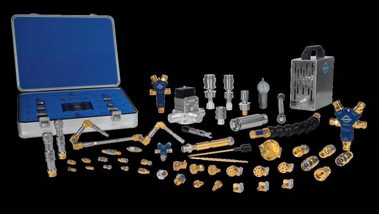
For these two calibration methods SPINNER offers an appropriate selection of calibration equipment ranging from the high-precision calibration kit for laboratory use to the compact designed calibration combinations for field use.
Kits are available with 7-16, 4.3-10, N, 2.2-5, NEX10®, 3.5 mm, 2.92 mm, 2.4 mm, 1.85 and 1.35 mm. In manufacturing such components, SPINNER has reached a level of precision that sets new standards which many desire.
SPINNER also offers a broad line of coaxial measurement equipment with excellent electrical and mechanical performance for use in laboratory and production environments at frequencies up to 165 GHz.
S-Parameter Measurement (VNA)
Testing of 75 Ohm Line Systems
Not only broadcasting systems, but also new communications applications use 75 ohm interfaces for high frequencies up to 18 or 20 GHz.
This has created a need for precise, reliable calibration and testing equipment that can be connected to 50-ohm vector network analyzers. SPINNER 75-ohm test adapters with type N connectors are now available in different versions to fill this gap.
SPINNER offers them in two forms: as a practical calibration kit with customized calibration coefficients and as a compact calibration tool with global coefficients. Both are characterized by outstanding accuracy and electrical specifications.
A typical application is testing of SDI 12G-compliant cables and interfaces, all of which have a resistance of 75 ohms. 12G supports a data rate of 12 Gbps. This SDI standard was developed to support greater resolution, frame rates, and color fidelity.
75-ohm systems can be measured with a 50-ohm vector network analyzer using a 75-ohm calibration kit and a proper unmatched mechanical adapter from 75-ohm to 50-ohm to avoid any damage on the inner conductor system.
For frequencies up to 20 GHz, which need be measured on a 26.5 GHz VNA with a ruggedized 3.5 mm test port, SPINNER provides a unique adapter from N 75 Ohm to ruggedized 3.5 mm male and female.
SPINNER understands how PIM performance can affect the growth of cellular networks and for decades has been devoting a huge R&D effort to offer a comprehensive portfolio of low-PIM products.
Passive intermodulation (PIM) is a form of intermodulation caused by the (generally very small) nonlinearities present in all passive components. When two or more frequencies are applied simultaneously, new and typically unwanted frequencies are generated.
If these frequencies are of sufficient power and fall into the frequency range of the receiving signal, they can significantly disturb the receivers of mobile base stations and negatively impact the quality of service. Symptoms include reduced bandwidth and even dropped calls.
Fixing the problem involves additional and often repeated investments for locating and replacing components with bad PIM behavior. At SPINNER we believe in avoiding these issues from the start.
We also set extraordinarily high standards with our definition of „low PIM“. Even most of our standard products such as connectors and jumpers feature a value of -160 dBc or better. Measuring the PIM properties of a component or system requires a measuring environment of sufficiently higher precision than the device under test.
Praxis
• Avoid all damage and contamination that may affect PIM values and make make sure that all RF-relevant electrical connections used for PIM measurement of free of metal particles dust, oxides and other contamination.
• All interseries adapters used for measurement should be designed as “PIM free” solutions with a single-piece inner conductor and a single-piece outer conductor.
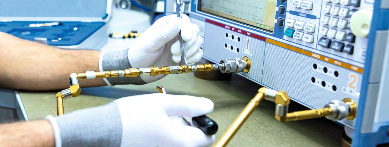
• It is strongly recommended to use a dial gauge to ensure the right pin depths on each connector, otherwise there is a risk of damage and/or deformation.
• When a bad connection is discovered, sometimes the first reaction is to overtighten it. Instead, all coupling nuts and cable inputs should be tightened using a torque wrench that is adjusted. This will help minimize PIM.
Preparation of Test Equipment
The following requirements must be met to obtain comparable PIM measurements:
• PIM measurement must always be done by experienced and skilled staff, otherwise there is a risk that results will be misinterpreted
• Measurement equipment (frequency sources, spectrum analyzers and power meters) must be regularly calibrated based on the applicable national or international calibration standard.
Optimize Your Test Chamber Setup
One of the problems that crop up when testing RF devices, machines, or vehicles in open-air environments is the large number of potentially interfering RF signals from radars, cellphones etc.
Mobile applications such as smartphones and tablets use high-speed connections, for example, to display or save steady high-resolution videos. The antennas that let these devices connect to a base station are increasingly broadband, which makes them more sensitive to electromagnetic interference.
The best way to test these devices is to place them in an isolated space called a low-reflection or anechoic chamber. Then intrinsic interference or interference radiation can be measured, coexistence tests can be carried out, or antenna characteristics can be verified.
RF test chambers are also used to measure radiated spurious emissions (RSEs) or antenna characteristics in an over-the-air (OTA) space.
Equipment development is usually concluded with measurements for certification known as the “first-time pass”.
But what about RF signals when the test equipment is outside a chamber? How can signals be routed in and out without large losses and additional interference?
SPINNER offers a whole line of highly suitable components for optimizing signal transmission between the test equipment and the device being tested in an RF anechoic chamber.
They range from precision-manufactured test port adapters across special flexible test cables and flexible waveguides to panel feedthroughs and both single- and multi-channel coaxial and waveguide rotary joints for frequency ranges from DC to 210 GHz.
As the market for millimeter wave sensors for self-driving vehicles expands, the demand for proper RF connections in testing environments is also growing.
Reliable coaxial interface connections are crucial for achieving good RF performance, especially in E-band applications. A common frustration in RF laboratories is unwanted unlocking of the 1.0 mm coaxial thread after performing time-consuming calibrations. This spawned the idea of a 1.35 mm connector the “E Connector” with a precise metric thread like the 1.85 mm connector plus an integrated time saving push-pull capability.
The E Connector is ideal for making high-performance RF measurements in the E-band without being held up by fragile 1.0 mm coaxial connector or wasting time reassembling WR 10 waveguides.
SPINNER designed the new 1.35 mm E Connector to close the gap between the 1.85 mm and the 1.0 mm coaxial connectors.
The 1.35 mm E Connector interface has been accepted for IEEE precision connector standard P287 and IEC 61169-65 now.
A manufacturer-independent supply of the new 1.35 mm E Connector is therefore ensured.
To ensure that a VNA delivers accurate amplitude and phase measurements without any drift, it is typically calibrated prior to each measurement. To do this, first the characteristic data of the various calibration standards are communicated to the VNA.
These characteristic data describe deviations from the ideal model. The calibration standards are then connected one after the other to the end of the test cable attached to the network analyzer.
The VNA then compares the measured values with the defined and known electrical properties of the calibration standard to calculate error terms. With their aid, all subsequently measured values are corrected to yield the actual values. If any change whatsoever is made to the test setup, no matter how small (slightly moving one of the test cables is enough), calibration is repeated before performing any additional measurements.
In fact, calibration is key for ensuring precise measurements. A VNA can be calibrated in various ways depending on the required degree of accuracy. The most frequently used calibration methods are OSL (open-short-load) for single-port measurements and OSLT (open-short-loadthrough) for two-port measurements.
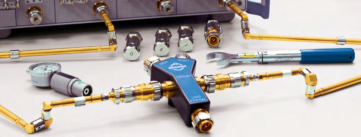
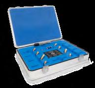
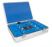
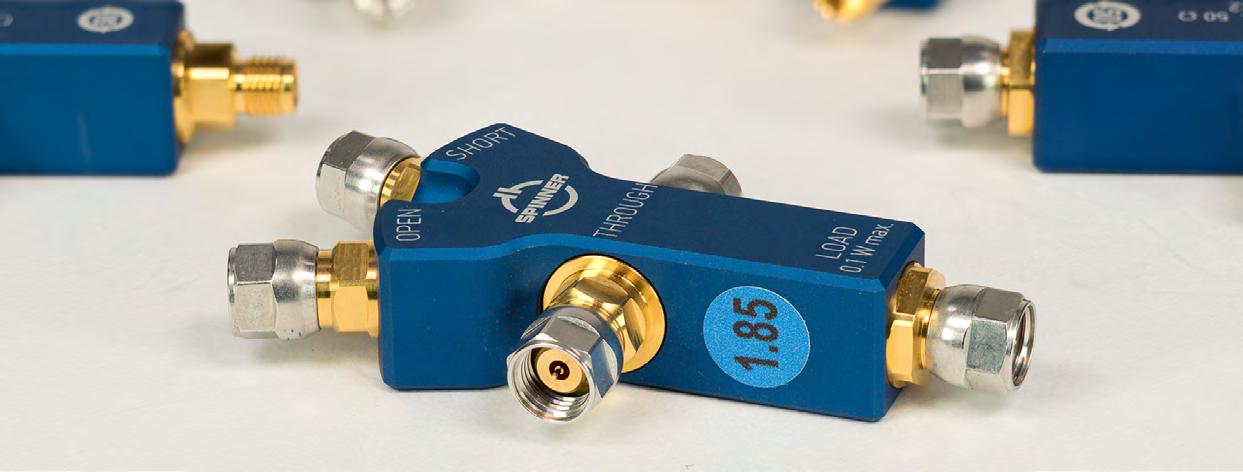
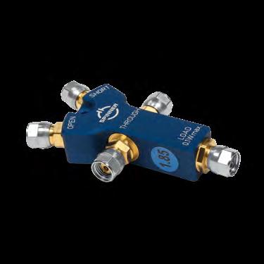
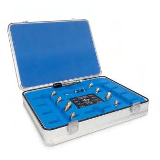
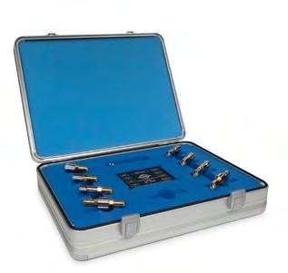
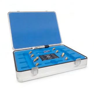
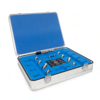
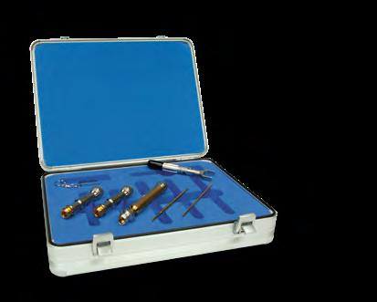
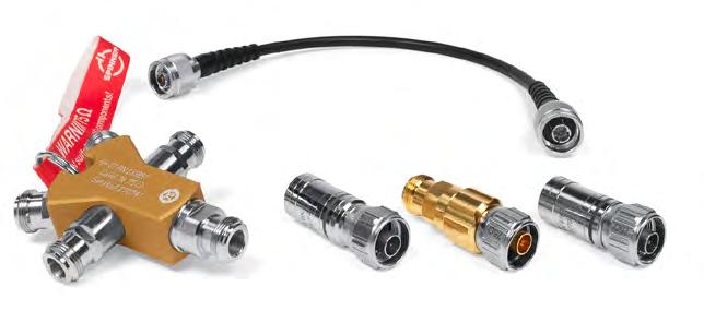
Compact calibration kits (3-in-1 and 4-in-1)
The combination of all calibration standards in one handy unit is the optimum solution for simple and comfortable handling during the calibration of network analyzers with the methods OSL and OSLT. The excellent handling, ergonomic arrangement of the components, small size and low weight are appreciated by in-field users as well.
Our 4-in-1 calibration kits include open, short, load and through-line for the complete calibration of a network analyzer with two or more ports with the OSLT method.
Our 3-in-1 calibration kits include all necessary standards for a complete OSL calibration of single port network analyzers, used for field testing of wireless network installations.
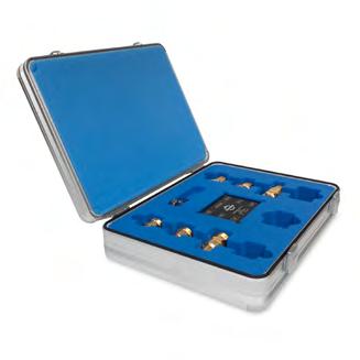
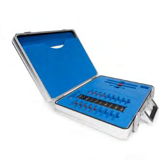
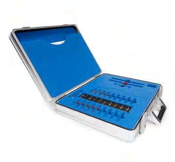
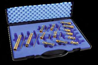
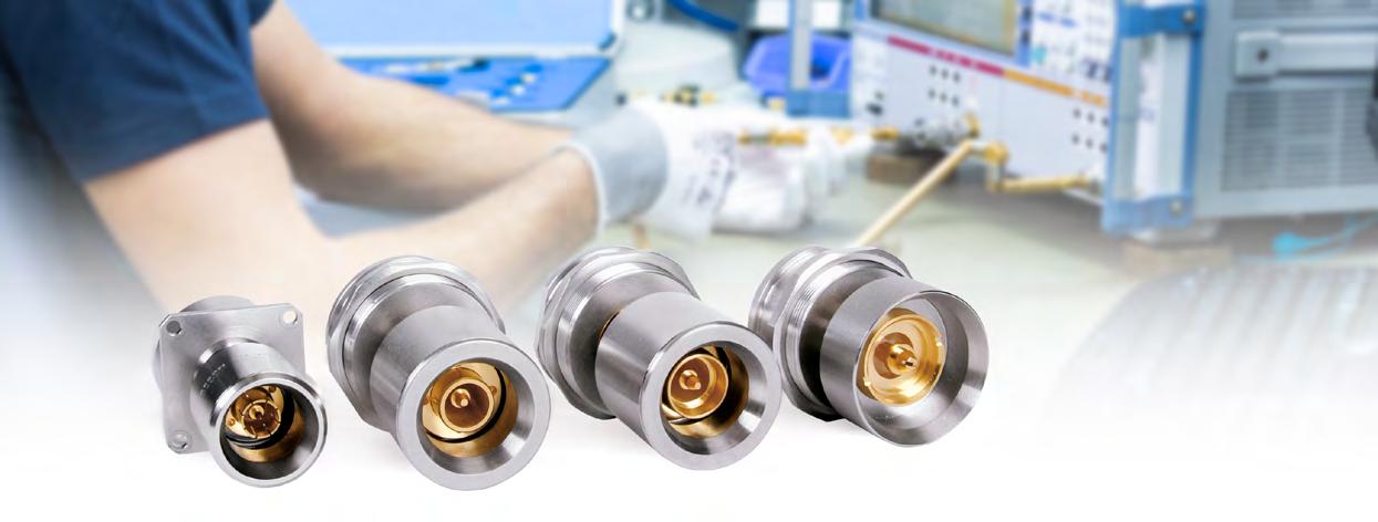
High-precision calibration kits up to the cut-off frequencies of the connector series
To achieve the best possible measurement results over the whole frequency range of a connector series the VNA is calibrated with one of several high-precision SPINNER calibration kits.
The calibration reference standards open circuit (Open), short circuit (Short) and fixed load (Load), each as a plug or socket, are included in our OSL calibration kits.
Additionally, our OSLT calibration kits include through adapters (Through), one with plug-to-plug and one with socket-to-socket connections. Optionally, a plug-to-socket adapter is available. All necessary data for the calibration are included.
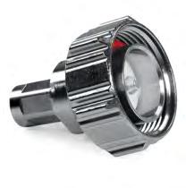
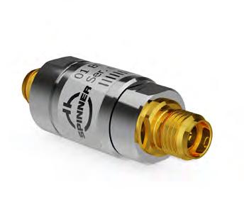
Calibration Kits, OSL, Compact 3-in-1, 50 Ω
The all-in-one compact calibration kit for a complete OSL calibration of a single port network analyzer used for field testing of wireless network installations
Open, short and load (OSL) in one compact handy device
Applicable to all VNA
For frequencies from DC to 6 GHz
BN 533176 BN 533177 Type N male Type N female
to18 GHz
@ DC to 6 GHz 3.5° @ 6 to 9 GHz 4.5° @ 9 to 18 GHz
@ DC to 6 GHz 3.0° @ 6 to 9 GHz 3.5° @ 9 to 18 GHz 42 dB @ DC to 6 GHz 33 dB @ 6 to 9 GHz 30 dB @ 9 to 18 GHz
BN 533174 BN 533175 3.5 mm male 3.5 mm female DC to 13 GHz 1.5° @ DC to 4 GHz 3.0° @ 4 to 8 GHz 4.5° @ 8 to 13 GHz 1.0° @ DC to 4 GHz 2.0° @ 4 to 8 GHz 3.5° @ 8 to 13 GHz 40 dB @ DC to 4 GHz 34 dB @ 4 to 8 GHz 28 dB @ 8 to 13 GHz
Calibration data in formats for the common VNAs are included in the kit.
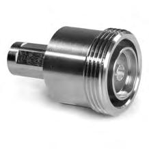
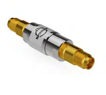
Calibration Kits, OSLT, Compact 4-in-1, 50 Ω
High precision while maintaining “always-thesame” global calibration coefficients
Open, short, load and through line (OSLT) in one compact handy unit for the complete calibration of a network analyzer with two or more ports with the OSLT method
Simplified calibration of more-port VNAs
Applicable to all VNA
Color coding for displaying interface size information
For frequencies from DC to 7.5 GHz up to DC to 70 GHz
BN 534913
BN 533760
BN 533759 2.4 mm male 2.4 mm female
to 4 GHz
to 10 GHz
to 26.5 GHz
to 40 GHz
to 50 GHz
Calibration data in formats for the common VNAs are included in the kit.
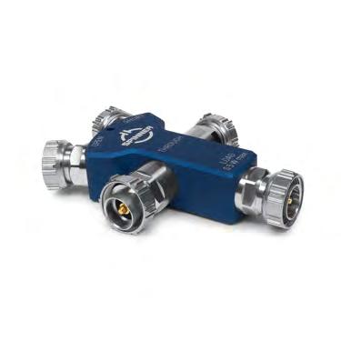
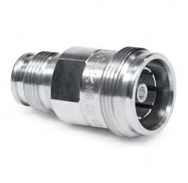
Calibration Kits, OSLT, Compact 4-in-1, 50 Ω
Open, short, load (OSL) and through-line (OSLT) in one compact handy device for the complete calibration of a network analyzer with two or more ports with the OSLT-method
Applicable to all VNA
Color coding for displaying interface size information
For frequencies from DC to 6 GHz up to DC to 13 GHz
Calibration data in formats for the common VNAs are included in the kit.
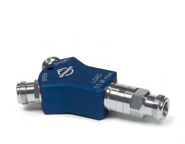
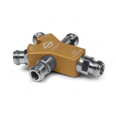
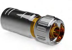
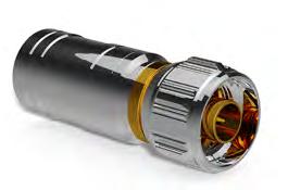
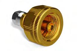
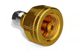
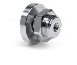
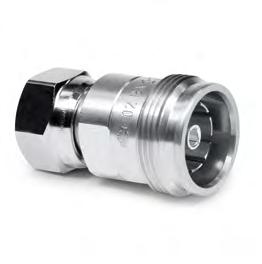
Calibration Kits, OSLT, Compact 4-in-1, 75 Ω
Open, short, load (OSL) and through (OSLT) in one compact handy device
Simplified calibration of more-port VNAs
Applicable to all VNA
Characteristic golden color in contrast to 50 Ohm kits
For frequency’s from DC to 3 GHz up to DC to 20 GHz
N 75 is a 75 Ω interface not intermateable with Type N (50 Ω) versions
Calibration
BN 533828
OSL High Precision Calibration Kits, 50 Ω
High-end S-parameter measurements
Open, short and load (OSL): each one in male and female version For frequencies from DC to 7.5 GHz up to DC to 18 GHz
7-16, DC to 7.5 GHz
Set Components
Type N, DC to 18 GHz
Part
BN 533831* Type N
Set components
1.5-3.5, DC to 13 GHz
* Calibration data in formats for the common VNAs are included in the kit. It includes individual calibration coefficients for every kit to achieve the best possible performance.
OSLT High Precision Calibration Kits, 50 Ω
High-end S-parameter measurements
Open, short, load and through (OSLT): each one in male and female version including through adapters, one with male-to-male and one with female-to-female connections
Optionally a male-to-female through is available
For frequencies from DC to 7.5 GHz up to DC to 12.5 GHz
7-16, DC to 7.5 GHz
Set components
4.3-10, DC to 12 GHz
male BN 806405R000BN 806404R000BN 533733R000BN 393307R000
* Calibration data in formats for the common VNAs are included in the kit. It includes individual calibration coefficients for every kit to achieve the best possible performance.
OSLT High Precision Calibration Kits, 50 Ω
"'" SPINNER '--'
High-end S-parameter measurements
Open, short, load and through (OSLT): each one in male and female version including through adapters, one with male-to-male and one with female-to-female connections
Optionally a male-to-female through is available
For frequencies from DC to 18 GHz up to DC to 20 GHz
Set components
male BN 533914R000BN 533912R000BN 533910R000BN 533916R000
* Calibration data in formats for the common VNAs are included in the kit. It includes individual calibration coefficients for every kit to achieve the best possible performance.
Type N, DC to 18 GHz
NEX10®, DC to 20 GHz
2.2-5, DC to 20 GHz
OSLT High Precision Calibration Kits, 50 Ω
3.5 mm, DC to 32 GHz
High-end S-parameter measurements
Open, short, load and through (OSLT): each one in male and female version including through adapters, one with male-to-male and one with female-to-female connections
Optionally a male-to-female through is available
For frequencies from DC to 32 GHz up to DC to 50 GHz
BN 533854* 3.5 mm
Set components
male BN 533764R000BN 533762R000BN 533766R000BN 533767R000
Set components male BN 534905R000BN 534903R000BN 534901R000BN 534907R000 female BN 534906R000BN 534904R000BN 534902R000BN 534908R000
* Calibration data in formats for the common VNAs are included in the kit. It includes individual calibration coefficients for every kit to achieve the best possible performance.
OSLT High Precision Calibration Kits, 50 Ω
1.85 mm, DC to 70 GHz
High-end S-parameter measurements
Open, short, load and through (OSLT): each one in male and female version including through adapters, one with male-to-male and one with female-to-female connections
Optionally a male-to-female through is available
For frequencies from DC to 70 GHz up to DC to 120 GHz
DC to 4 GHz ≥ 36 dB 4 to 10 GHz ≥ 31 dB 10 to 26.5 GHz ≥ 25 dB 26.5 to 70 GHz ≥
Set components
male BN 534931R000BN 534929R000BN
1.0 mm, DC to 116.5 GHz (resonance free up to 120 GHz)
Set components
male BN 535733 BN 535735 BN 535737 BN 535739
female BN 535734 BN 535736 BN 535738 BN 535740
Option male-female BN 535741
* Calibration data in formats for the common VNAs are included in the kit.
It includes individual calibration coefficients for every kit to achieve the best possible performance.
** Calibration data in formats for the common VNAs are included in the kit.
Determined S-parameters for open, short and load.
OSLT High Precision Calibration Kits, 50 Ω
0.8 mm with an improved frequency range from DC to 150 GHz, basic version
530850*
High-end S-parameter measurements
Open, short, load and through (OSLT): each one in male and female version including through adapters, one with male-to-male and one with female-to-female connections
Gauges and torque wrenches
For frequencies from DC to 150 GHz
male BN 530831 BN 530833 BN 530839 BN
0.8 mm with an improved frequency range from DC to 150 GHz, pro version
* Calibration data in formats for the common VNAs are included in the kit. Determined S-parameters for open, short and load.
OSLT High Precision Calibration Kits, 50 Ω
0.8 mm with an extended frequency range from DC to 165 GHz, max version
High-end S-parameter measurements
Open, short, load and through (OSLT): each one in male and female version including through adapters, one with male-to-male and one with female-to-female connections
Gauges and torque wrenches
For frequencies from DC to 165 GHz
Set components male BN 530831 BN 530833
530839
530841 female BN 530832 BN 530836 BN 530840
530844
530845
Elements for determining the extended frequency range Offset-Short
530847
530815
530816
238749C0001
4.554 mm 5.179 mm R 1.4k (WR 7) to 0.8 mm
male BN 530834 BN 530835 BN 533193
female BN 530837 BN 530838 BN 533192
* Calibration data in formats for the common VNAs are included in the kit.
Determined S-parameters for open, short and load.
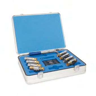
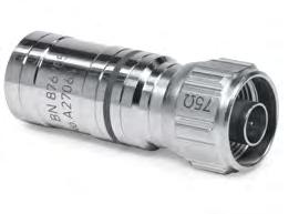
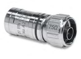
OSLT High Precision Calibration Kit, 75 Ω
534046*
High-end S-parameter measurements
Open, short, load and through (OSLT): each one in male and female version including through adapters, one with male-to-male and one with female-to-female connections
Optionally a male-to-female through is available
For frequencies from DC to 20 GHz
N 75 is a 75 Ohm interface not intermateable with Type N (50 Ohm) versions
* Calibration data in formats for the common VNAs are included in the kit. It includes individual calibration coefficients for every kit to achieve the best possible performance.
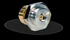
Precision Open Circuit Terminations, 50 Ω, Instrument Grade
BN 533764R000 3.5 mm male
BN 533763R000 3.5 mm female
BN 534905R000 2.92 mm male
BN 534906R000 2.92 mm female
BN 533774R000 2.4 mm male
BN 533775R000 2.4 mm female
BN 533425R000 1.85 mm male
BN 533426R000 1.85 mm female
to 32 GHz
to 44 GHz
to 50 GHz
to 70 GHz
Contoured end cap fits to spanner SW 8 as well
Calibration certificate included
to 26.5 GHz ≤ 2.0°
to 50 GHz ≤ 3.5°
to 70 GHz ≤ 4.5°
BN 534931R000 1.35 mm male DC to 90 GHz DC to 26.5 GHz ≤ 2.0° 26.5 to 50 GHz ≤ 3.5°
BN 534932R000 1.35 mm female
BN 535733 1.0 mm male DC to 116.5 GHz
BN 535734 1.0 mm female
BN 530831 0.8 mm male
BN 530832 0.8 mm female
Defined by deternination of S parameters
to 150 GHz DC to 40 GHz ≤ 2.5° 40 to 90 GHz ≤ 3.5° 90 to 120 GHz ≤ 5.5° 120 to 150 GHz ≤ 7.0°
Precision Short Circuit Terminations, 50 Ω, Instrument Grade
Contoured end cap fits to spanner SW 8 as well
Calibration certificate included
BN 530836 0.8 mm female
Precision Offset Short Circuit Terminations, 50 Ω
Contoured end cap fits to spanner SW 8 as well
Calibration certificate included
Precision Matched Loads, 50 Ω, Instrument Grade
Contoured end cap fits to spanner SW 8 as well
Calibration certificate included
Precision Through Adapters, 50 Ω, Instrument Grade
Part
BN 393307R000
BN 196404R000
BN 756301R000
BN 533309R000
BN 533310R000
BN 533311R000
BN 533916R000
BN 533917R000
BN 533918R000
BN 355109R000
BN 355110R000
male screw 4.3-10 female 4.3-10 male screw-female
BN 355111R000 NEX10® male screw
BN 225309R000
BN 225310R000
BN 225311R000 2.2-5 male screw 2.2-5
BN 533767R000
BN 533768R000
BN 533769R000
BN 534907R000
BN 534908R000
BN 533776R000
BN
BN 534933R000
BN 534934R000
BN
Contoured end cap fits to spanner SW 8 as well
Calibration certificate included
BN 535741
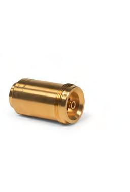
Precision Open Circuit Terminations, 75 Ω, Instrument Grade
Precision Short Circuit Termination, 75 Ω, Production Grade
Precision Short Circuit Terminations, 75 Ω, Instrument Grade
Precision Matched Load, 75 Ω, Production Grade
Precision Matched Loads, 75 Ω, Instrument Grade
534065R000
N 75 Ohm male
BN 534066R000 Type N 75 Ohm female
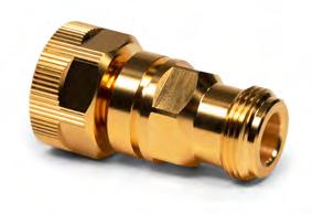
Precision Through Adapters, 75 Ω, Instrument Grade
BN 534067R000
BN 534068R000
N 75 Ohm male
N 75 Ohm female BN 534069R000
N 75 Ohm male-female
Precision Air Lines – Bead-Supported
BN 533692 7-16 male-female
BN 533693 7-16 female-female
BN 533690 Type N male-female
BN 533691 Type N female-female
DC to 7.5 GHz
DC to 18 GHz
BN 533694 3.5 mm male-female DC to 34 GHz
BN 533695 3.5 mm female-female
Verification Kit
Applicable to all VNAs
25 Ω mismatch center conductor incl. guiding device
Other interfaces on request.
LRL Calibration Kit
High-end S-parameter measurements
Very accurate for phase measurements
Very good effective directivity and testport-match => uncertainty is smaller compared to OSLT- (TOSM-) calibration
Center- and outer conductor are matched in their lengths to avoid gaps during calibration
Other interfaces on request. * The actual electrical length of the air lines and shorts can be taken from the technical data which is included in delivery.
Measurement Accessory Kit for 75 Ω Direct Access Units
Application Note: "TD-00178 Direct Access Units" https://www.spinner-group.com/images/download/technical_documents/SPINNER_TD00178.pdf
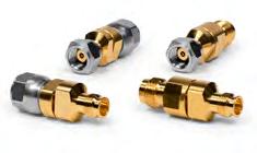
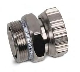
Adapters
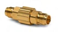
Whenever the connector system of the VNA and the object to be measured do not match, special transitions, so called adapters, are required.
Adapters are used to connect line elements of different connection sizes (so-called inter-type or between-line adapters) or within one size but of different connection genders (so-called within-type or in-line adapters). The term transition connector is also used as another common term for adapters.
For example, the object to be measured has connections of type 4.3-10 plug and all measuring ports have the connector system 3.5 mm plug.
As a result, the available maximum frequency of the test ports is usually limited by the use of a different connector system. For example, when using a 4.3-10 connector system on a VNA with a 3.5 mm connector system, the frequency is limited to 12 GHz instead of 26.5 GHz.
Some connector systems do not require an adapter, as they are at least mechanically compatible with each other: 3.5 mm with SMA, 2.92 mm and vice versa, 2.4 mm with 1.85 mm and vice versa.
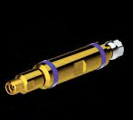
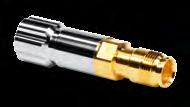
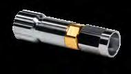
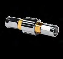
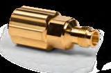
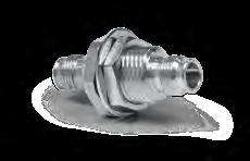
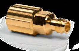
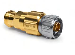
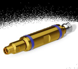
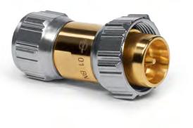
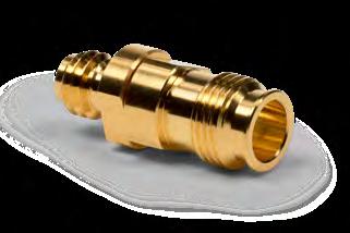
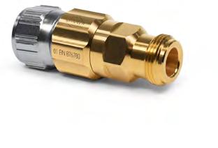
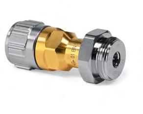
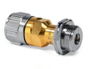
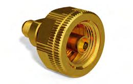
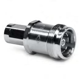
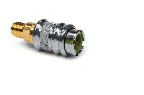
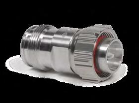
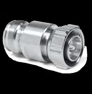
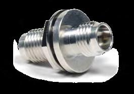
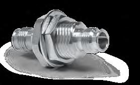
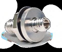
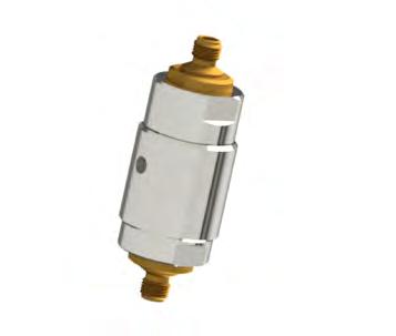
Push Pull Adapters
SPINNER push-pull adapters provide excellent mechanical stability and a fast and accurate method for continuous connects and disconnects without the time-consuming tightening of the connector with a torque wrench.
The adapter is quickly and easily mated and de-mated by pulling its coupling nut backwards, pushing it onto the corresponding connector and loosening the nut.
Our technology is compatible with any standard socket in the corresponding connector series. The use of high-quality materials ensure the adapter’s ability to produce precise connections and maximize its lifetime.
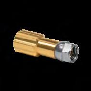
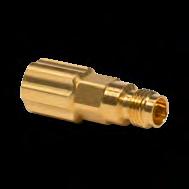
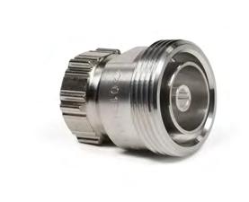
Precision Inter-Type Adapters, 50 Ω
BN 194403
BN 293803
BN 293903
BN 294003
BN 194440 BN 194441
BN 432042 BN 432043
BN 640625 BN 640627 BN 640628
640643
BN 355144
BN 355145
BN
BN 534921R000
BN 534922R000
BN 534917R000
BN 534918R000
BN 534919R000
BN 534920R000
BN 533166
BN 533167
Precision Within Type Adapters 50 Ω
Precision Within Type Adapters 50 Ω – Thermally Insulated
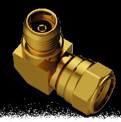
Precision Within Type Adapters Right-Angle
For frequencies up to 67 GHz
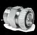
Lowest return loss
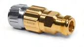
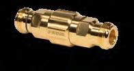
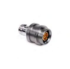
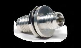
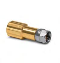
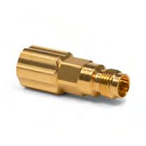
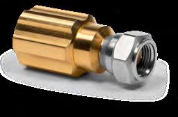
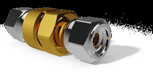
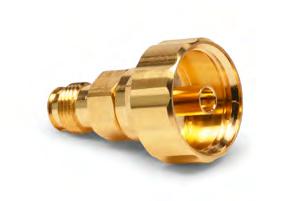
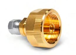
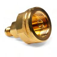
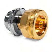
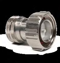
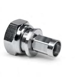
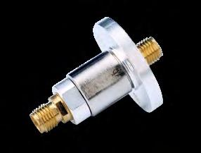
Precision Inter-Type Adapters 50 Ω to 75 Ω (Mechanically Only)
For frequencies from DC to 20 GHz
N 75 is a 75 Ohm interface not intermateable with Type N (50 ohms) versions
Unmatched version
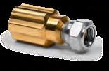
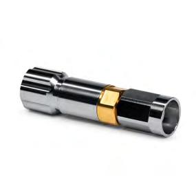
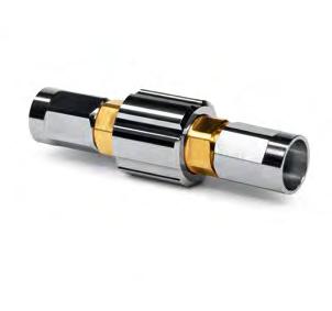
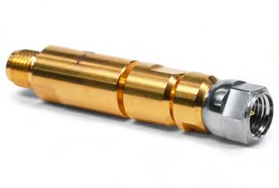
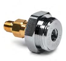
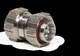
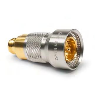
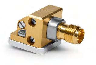
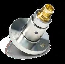
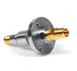
Precision Inter-Type Test Port Adapters – One-Sided Ruggedized
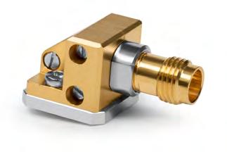
Precision Inter-Type Test Port Adapters – One-Sided Ruggedized
Precision Inter-Type Test Port Adapter – One-Sided Ruggedized
Precision Inter-Type Test Port Adapter – Double-Sided Ruggedized
BN
Precision
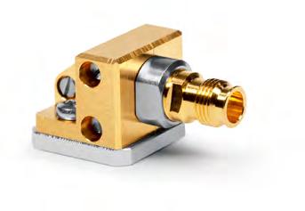
Within-Type Test Port Adapters – One-Sided Ruggedized
Precision Within-Type Test Port Adapters – One-Sided Ruggedized
*Amongst others especially suitable to ANRITSU VNA broadband millimeter-wave module with “Adapter Mounting Bracket” to stabilize the sophisticated coaxial 1.0 mm test port.
BN
Precision Within-Type Test Port Adapter – Double-Sided Ruggedized
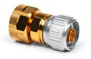
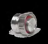
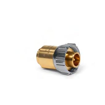
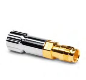
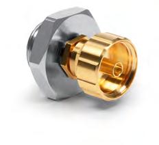
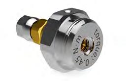
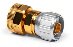
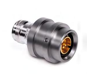
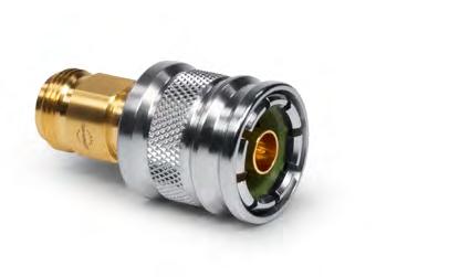
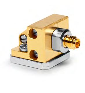
Precision Inter-Type Test Port Adapter, 75 Ω to 50 Ω – One-Sided Ruggedized
Precision interface
For frequencies from DC to 20 GHz
Well-defined reference plane
Maximized retur n losses
High connector repeatability (min. 45 dB)
Suitable for precision measurement of S parameters
Impedance 50 Ohm / 75 Ohm unmatched
3.5 mm interface is designed as a rugge- dized version
Precision interface
For frequencies from DC to 20 GHz
Well-defined reference plane
Maximized retur n losses
High connector repeatability (min. 45 dB)
Suitable for precision measurement of S parameters
Impedance 50 Ohm / 75 Ohm unmatched
3.5 mm interface is designed as a rugge- dized version
* N 75 ohm is a 75 ohm interface not intermateable with type N 50 ohm versions.
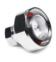
Inter-Type Adapters 7-16 to 4.3-10
For sensitive testing and measurement applications
Lowest intermodulation
Abrasion-proof
Tar nishing and corrosion proof
Nickel-free
RoHS-compliant
VSWR,
Passive intermodulation (IM3) @ 2 x 20 W
Weight
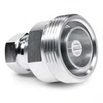
Inter-Type Adapters 7-16 to 2.2-5
≤-165 dBc
95 g
For sensitive testing and measurement applications
Lowest intermodulation
Abrasion-proof
Tar nishing and corrosion proof
Nickel-free
VSWR, max. Max. 1.04 @ DC to 2 GHz
1.06 @ 2 to 4 GHz
1.10 @ 4 to 6 GHz
Passive intermodulation (IM3) @ 2 x 20 W
Weight ≈ 70 g
Inter-Type Adapters 7-16 to NEX10®
For sensitive testing and measurement applications
Lowest intermodulation
Abrasion-proof
Tar nishing and corrosion proof
Nickel-free
RoHS-compliant
VSWR,
Inter-Type Adapters 4.3-10 to 2.2-5
For sensitive testing and measurement applications
Lowest intermodulation
Abrasion-proof
Tar nishing and corrosion proof
Nickel-free
RoHS-compliant
Passive intermodulation (IM3) @ 2 x 20 W
"'" SPINNER '--'
Inter-Type Adapters 4.3-10 to NEX10®
For sensitive testing and measurement applications
Lowest intermodulation
Abrasion-proof
Tar nishing and corrosion proof
Nickel-free
RoHS-compliant
Passive
Within-Type Adapters
For sensitive testing and measurement applications
Lowest intermodulation
Abrasion-proof
Tar nishing and corrosion proof
Nickel-free
RoHS-compliant
Push-Pull Adapters
Part Number
Quick connector for port or connector saving tasks
Lowest intermodulation
Lockable
Unlockable in jig via automated handling
Quick & reliable connection
Extremely compact
Guaranteed matings
BN 432051
Coaxial DUT port interface connector 4.3-10 male push-pull
Coaxial outgoing (Analyzer) port interface connector4.3-10 female
Passive intermodulation (IM3) @ 2 x 20 W
Insertion loss
Isolation
Matings
Weight
Max. ≤-165 dBc; typ. ≤-168 dBc
Max. 0.05 dB
90 dBc
Min. 5001)
190 g
1) For optimal measurement results, cleaning must be regularly performed and assessed by expert staff.
Push-Pull Adapters
*The pressure-ring (green rubber) in the connector head included is a wearing part and should be replaced after approx. 5,000 mating cycles
Accessories for Push-Pull Adapters
A09431 Pressure-Ring (green rubber) for BN 950870
A09636 Pressure-Ring (green rubber) for BN 640570
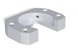
SPINNER EasyDock – 1.35 mm Blind Mate Adapters
Part Number
For jig operated test applications in production lines
Precision interfaces with Well-defined reference plane
Maximized retur n losses
High connector repeatability (min. 45 dB)
Suitable for precision measurement of S-parameters
In-line style: DC open circuit
Right-angle style: DC short circuit
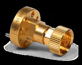
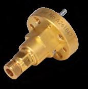
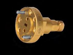
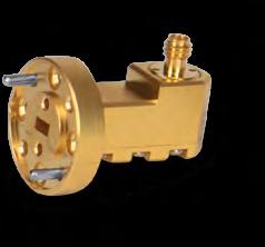
BN 533192 Right-angle
BN 533193 Right-angle
BN
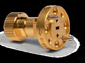
waveguide
BN 533134 In-line
BN 533190 Right-angle
BN 533194 In-line
BN 533195 In-line
waveguide to coaxial adapter R 260 (WR 34) to 2.92 mm female
waveguide to coaxial adapter R 260 (WR 34) to 2.92 mm
Accessories for mmWave Waveguide-to-Coaxial Adapters
Part NumberDescription
A61785 Aligning pin
Part NumberDescription
A61786 Socket-head cap screws 4-40 UNC
Part NumberDescription
A62935 Protective cap
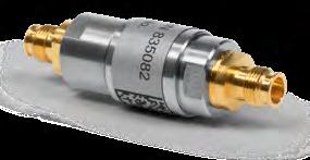
Passive Intermodulation Reference Standards
General
Frequency range
Passive intermodulation level 3rd order*
*±3 dB at 2 x 43 dBm / 2 x 20 W carrier
Coaxial interface connector
Frequency band
GSM 900
fIM3: 890.3 MHz
GSM 1800
fIM3:1730 MHz
UMTS
fIM3: 2050 MHz
LTE 2.6
fIM3: 2550 MHz
More information:
f1: 925.1 MHz
f2: 959.9 MHz
f1: 1805 MHz
f2: 1880 MHz
f1: 2110 MHz
f2: 2170 MHz
f1: 2620 MHz
Generates a defined intermodulation product for test purposes
Guaranteed intermodulation
High accuracy
Excellent repeatability
DC to 4 GHz
7-16 male - female (50 Ω)
Part number starting with BN 756616….
To specify a type, please add a suffix from the table below.
C0070C0080C0090C0100C0110C0120
C1070C1080C1090C1100C1110C1120
C2070C2080C2090C2100C2110C2120
C3070C3080C3090C3100C3110C3120 f2: 2690 MHz
More information: BN 756617Cxxxx BN 756616Cxxxx
Coaxial interface connector
4.3-10 male - female (50 Ω)
Frequency band Part number starting with BN 756617…. To specify a type, please add a suffix from the table below.
GSM 900
fIM3: 890.3 MHz
GSM 1800
fIM3:1730 MHz
UMTS
fIM3: 2050 MHz
LTE 2.6
fIM3: 2550 MHz
f1: 925.1 MHz
f2: 959.9 MHz
f1: 1805 MHz
f2: 1880 MHz
f1: 2110 MHz
f2: 2170 MHz
f1: 2620 MHz
f2: 2690 MHz
Example:
C0070C0080C0090C0100C0110C0120
C1070C1080C1090C1100C1110C1120
C2070C2080C2090C2100C2110C2120
C3070C3080C3090C3100C3110C3120
BN 756616C1090: Intermodulation standard with -90 dBm for band GSM 1800, interface 7-16 male-female
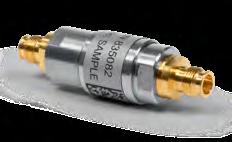
Passive Intermodulation Reference Standards
General
Generates a defined intermodulation product for test purposes
Guaranteed intermodulation
High accuracy
Excellent repeatability
Frequency range DC to 4 GHz
Passive intermodulation level 3rd order*
*±3 dB at 2 x 43 dBm / 2 x 20 W carrier
Coaxial interface connector NEX10® male - female (50 Ω)
Frequency band
900 MHz
fIM3: 890.3 MHz
1800 MHz
fIM3:1730 MHz
2100 MHz
fIM3: 2050 MHz
2600 MHz
fIM3: 2550 MHz
More information:
f1: 925.1 MHz
f2: 959.9 MHz
f1: 1805 MHz
f2: 1880 MHz
f1: 2110 MHz
f2: 2170 MHz
f1: 2620 MHz
f2: 2690 MHz
BN 756618Cxxxx
Part number starting with BN 756618….
To specify a type, please add a suffix from the table below.
C0070C0080C0090C0100C0110C0120
C1070C1080C1090C1100C1110C1120
C2070C2080C2090C2100C2110C2120
C3070C3080C3090C3100C3110C3120
Example:
BN 756618C1090: Intermodulation standard with -90 dBm for band GSM 1800, interface NEX10® male-female
Panel Connectors and Cables "'" SPINNER '--'
RF panel mount and cable connectors are found in a wide range of applications such as communication infrastructure, medical, research, industrial, aerospace and defence, automotive and consumer products, and must operate reliably even under the most difficult conditions.
No matter where the application is, SPINNER guarantees the best transmission characteristics, enables high bandwidths and signal integrity and offers a robust design.
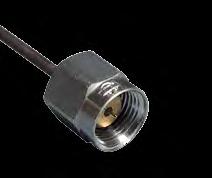
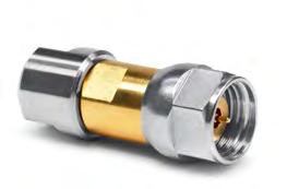
RF cable connectors from SPINNER are provided in standard or custom configurations with cable entries and soldering sleeves for the most common 50 Ohm RF cable types.
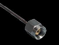
Connectors for RF cables are available for: 1.0 mm, 1.35 mm, 1.85 mm, 2.4 mm, 2.92 mm, 3.5 mm, 1.5-3.5 in male or female straight, male push-pull as well as a bulkhead, D-hole or 4-hole panel mount version.
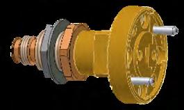
Thru-male
For instrument wiring, we offer precision-manufactured cable connectors with the lowest insertion loss. The inner cable conductor is also the inner connector conductor. There is no need for time-consuming soldering to the connector ferrule.
As the connections in the devices are only contacted once, the wear of the cable inner connector pin is negligible.
Sometimes it is also necessary for space reasons to connect a cable for higher frequencies to a cable connector for a low frequency. These cables are thinner and easier to bend and thus allow installation in the tightest of spaces. The somewhat higher attenuation values are neglected in this case.
SPINNER cable connectors are all especially suitable for use with semi-rigid cables. 3.5 mm is intermatable with 2.92 mm (K) connectors, the 2.4 mm with the 1.85 mm connectors.
With the 1.35 mm E-connector standard, a coaxial connector system is on the market that enables applications up to 90 GHz. The E-connector offers a more reliable mechanical locking than the 1.0 mm coaxial connector system and is perfect suited for many test applications in the field of automotive radar.
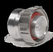
Coaxial Panel Connectors
Coaxial Panel Connectors
Waveguide Panel Connector
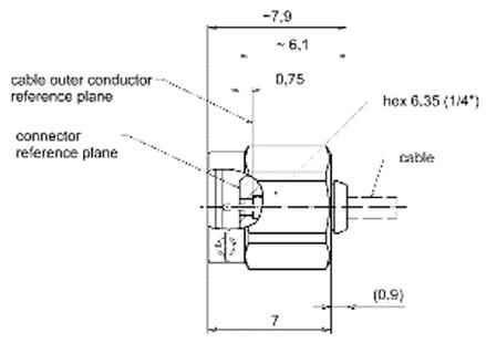
Cable Connector for Cable UT-047
BN 534942C0001* 1.35 mm male with 10° solder cup
Cable Connector for Cable UT-047 and UT-047-LL
Features “Thru male” design: Pin diameter equals center conductor of MIL-DTL-17/151 and other standard cables – enables high-quality low-budget jumper cables
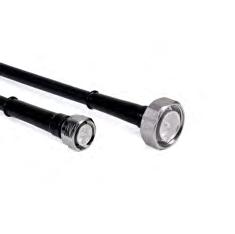
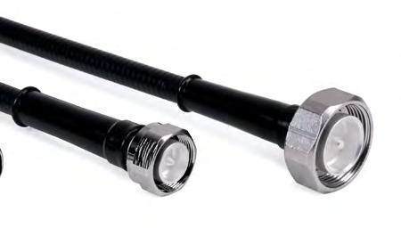
Low PIM Measurement Cable Assemblies
Outstanding IM performance 100% PIM tested; with protocol
Straight and right angle 7-16, 4.3-10, 2.2-5 or NEX10® connectors
Lengths: min. 0.13 m; max. 30 m
Optimized for repeated bending
Reinforced cable ends
For indoor use only (no O-ring in connector interface)
Article Low PIM SpinnerFlex® TopFit Cable SF 3/8“
Article Low PIM SpinnerFlex® TopFit Cable SF 1/2“
1) The provided VSWR values are maintained within all global cellular frequency bands.
Any combination of connectors below is possible. Please specify XZ combination for connectors 1 and 2.
screw 43MS
right angle; screw 22RS
Length in meters/feet (dependent on unit specified)
Length in decimeters/inch (dependent on unit specified)
Low PIM Measurement Cable (only available with PE jacket) -
intermodulation (IM3) @ 2 x 20 W ≤ -165 dBc1), inspection certificate 3.12), per jumper
- Passive intermodulation (IM3) @ 2 x 20 W ≤ -165 dBc1), inspection certificate 3.12), per order
- Passive intermodulation (IM3) @ 2 x 20 W ≤ -170 dBc1), inspection certificate 3.12), per jumper
- Passive intermodulation (IM3) @ 2 x 20 W ≤ -170 dBc1), inspection certificate 3.12), per order
1) According to IEC 62037-2 and WN 20 000
2) According to EN 10204
Examples of sales article numbers:
JS38-7M7F-2M-I3: SF 3/8” jumper with 7-16 male and 7-16 female; length 2.0 meter; low PIM performance with ≤ -165 dBc; test protocol per order.
JS12-7M43RS-1M3-I5: SF 1/2” jumper with 7-16 male and 4.3-10 female right angle screw; length 1.3 meter; low PIM performance with ≤ -170 dBc; test protocol per jumper.
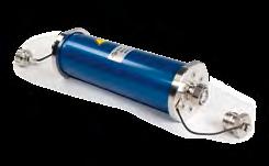
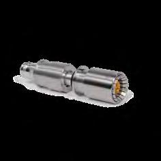
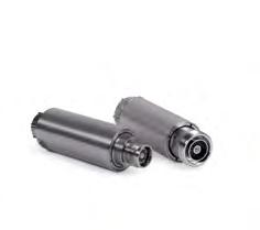
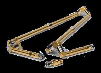
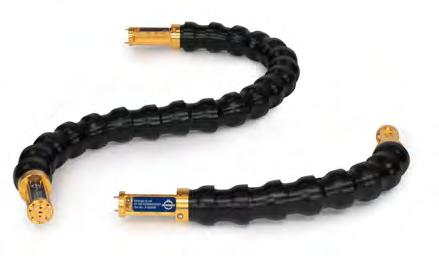
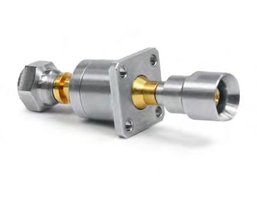
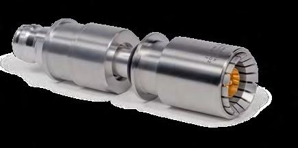
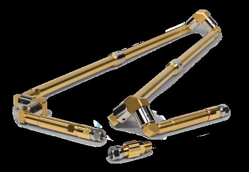
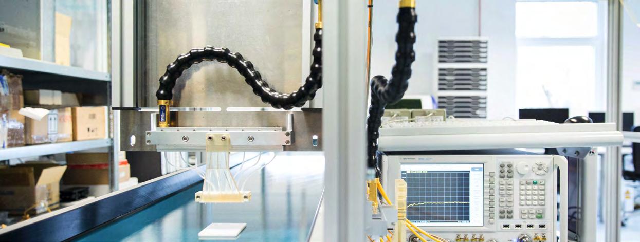
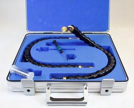
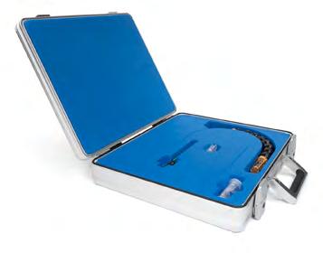
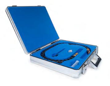
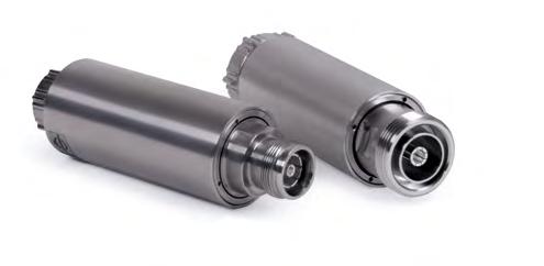
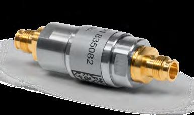
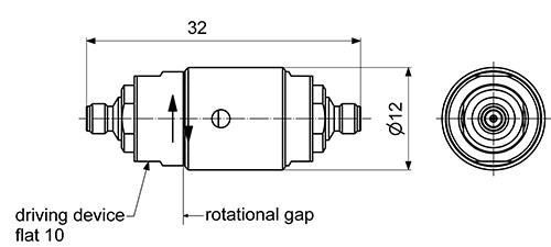
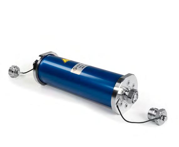
Coaxial Articulated Lines
Articulated lines boast excellent RF properties and an extremely long service life. They are considerably more robust than ordinary test cables, lasting several times as long.
Features
• Extremely long life
- 1 million flex cycles guaranteed for articulated line (The rotary joints allow movements without stressing of the material by strain or torsion)
- Wor n-out port saver connectors (5000 matings guaranteed) can be easily replaced by customer
• Excellent amplitude and phase stability
- Also during movement
- Also with temperature drift
• Accurate and reproducible RF measurements
- No need for adapters because 3.5 and N connectors are available as male and female
- VNA calibration is not affected by movements
• Highly flexible
- DUT ports in any orientation can be connected within a sphere 1 m in diameter (0.5 m for short line)
- Rotation allowed
- No mechanical stress introduced to DUT
• Ecofriendly
- Long life
- Repair-friendly
- Recyclable
Applications
• General test bench use
• Network analysis (S-parameter measurement)
• Robotic test setups
• Measurement of rotatable DUTs (e.g. rotary joints and rotating systems)
YouTube - Articulated Lines SPINNER RF Articulated Lines contra RF test cables
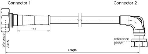
Coaxial Articulated Lines, DC to 18 GHz – 365 mm
possible variations of mechanical alignment
min. and max. dimension _N~1~42=----+<~----+--+between center lines
max. reachable length from reference plane to reference plane
Coaxial Articulated Lines, DC to 18 GHz – 650 mm
possible variations of mechanical alignment r~500
from the center of a globe with radius ~500 every position is reachable maximum reachable length from reference plane to reference plane ~650 mm.
Coaxial Articulated Lines, DC to 32 GHz – 320 mm
BN
BN
Coaxial Articulated Lines, DC to 32 GHz – 650 mm
Coaxial Articulated Lines, DC to 40 GHz – 320 mm
Coaxial Articulated Lines, DC to 50 GHz – 345 mm
Coaxial Articulated Lines, DC to 67 GHz – 315 mm
533652C1010
BN 533652C2211 1.85
BN 533652C3311
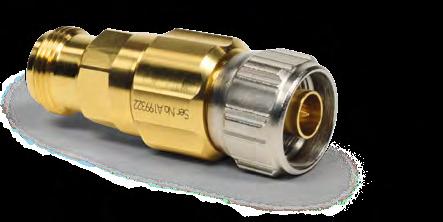
Port Savers for Coaxial Articulated Lines
BN 533917C0001 Type N female-female
BN 533918C0001
BN 533778C0001 2.4 mm male-female
High-precision adapter in instrument quality
Minimize wear at articulated line ports
Male-male, female-female, or male-female available
For frequencies up to 50 GHz
SPINNER EasySnake – The Flexible Terahertz Waveguide Assembly
SPINNER EasySnake for E- and W-band performs the function of a hollow metallic waveguide but offers two degrees of freedom: flexible bending and twisting in any direction while delivering excellent measurement results at the same time. Even conventional flexible waveguides made of electrically conductive bellows are typically non-twistable i.e. resist torsion, which significantly limits the feasible test configurations.
They are also completely intolerant of minimally misalign or twisted flanges. The SPINNER EasySnake overcomes this by combining the flexibility of a conventional RF measurement cable with the excellent low-loss transmission characteristics of a conventional non-flexible waveguide system.
Features
Dielectric waveguide supported by unique tubular segments (patent pending)
Flexible, i.e. bendable and twistable (eliminates installations problems caused by misalignment of flanges)
Flex-stable, i.e. keeps chosen bending geometry
Built-in transitions from dielectric to rectangular waveguide
Insertion loss outperforms any coaxial cable and single-mode metallic waveguide
Excellent amplitude stability with flexure and temperature change
Length configurable in steps of 25 mm
Mechanically protected and electrically shielded
High-voltage decoupled waveguide transitions
Applications
General test bench use
Network analysis (S-parameter measurement)
Antenna testing (near field, far field)
Conference Paper
Nickel, H.-U. and Zovo, J., 2014, Novel flexible dielectric waveguide for millimeter and sub-millimeter frequencies – Design and characterization, 84th ARFTG Microwave Measurement Conference (ARFTG 84th), Boulder, Colorado, USA, Proceedings.
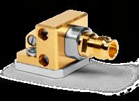
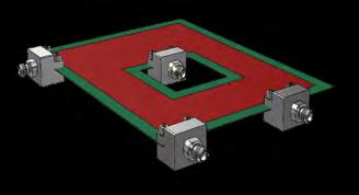
There is an increasing demand for millimeter wave signal pickup on printed circuit boards (PCBs). However, existing solutions either limit the range of possible PCB layouts or reduce RF performance.
In most cases, layout designs are limited by the need to solder PCB adapters to the edge of the board. The worst case is when the board includes cavities for picking up RF signals somewhere in the middle.
Other solutions that involve taping RF signals in the middle of the board impair RF performance since the PCB Adapter’s still inner conductor pricks the surface.
Conventional Solution
Area not usable with conventional PCB Adapters
Adressable area for conventional PCB Adapters
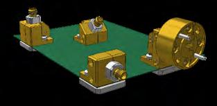
The
Benefits
Excellent RF performance:
The soft-launch concept avoids compromising the PCB surface, even when there are multiple launches.
Support for more compact PCB designs: The SPINNER EasyLaunch Adapter can be positioned anywhere.
The
Solution
The flexible, soft-launch SPINNER EasyLaunch is mounted flush with the PCB surface and ensures excellent RF performance, even with multiple launches.
This technology permits variable positioning of the connectors and maximizes flexibility for placing RF contact.
Advantages of SPINNER EasyLaunch
Variable positioning for maximimum flexibility
Excellent RF performance for the highest frequencies
Compact board design
SPINNER EasyLaunch Solution
SPINNER PCB Adapters can be positioned anywhere
The SPINNER EasyLaunch Adapter and PCB board can be easily reused—no soldering required. Flush contact with the PCB
Support for a wide range of PCB substrates
The fixed connector interface can be ordered for any angle between 0° and 90°.
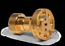
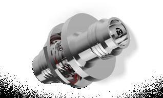
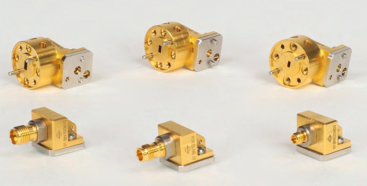
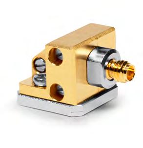
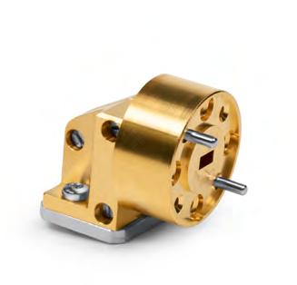
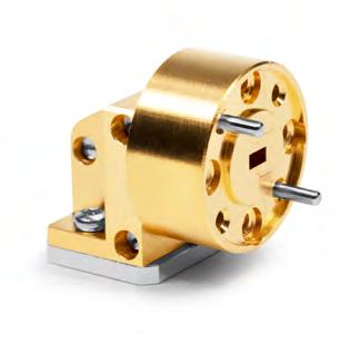
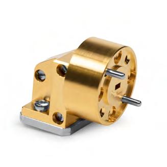
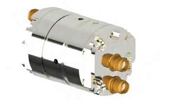
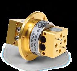
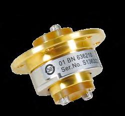
SPINNER rotary joints excel with compact designs, excellent VSWR, low insertion losses, minimal fluctuation of transmission characteristics while rotating, and high crosstalk attenuation between individual channels across the entire range of frequencies used.
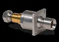
Noncontacting Rotary Joints
Noncontacting RF rotary joints (RJ) are available in coaxial and waveguide designs for frequency ranges up to 100 GHz. They are characterized by an especially long service life. Signal transmission is possible at a bandwidth of about 20% of the highest transmitted frequency.
Noncontacting rotary joints are used for narrow-band transmission. With special coupling structures, the same module can also be used to transmit two different frequency bands (e.g. the X and L bands).
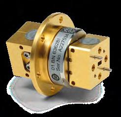
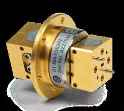
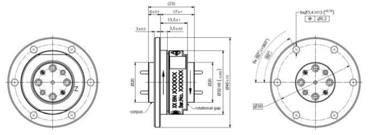
Contacting Rotary Joints
In contacting rotary joints, the inner and outer conductors of the stator and rotor are DC-coupled.The maximum frequency depends on the diameter of the coaxial line. These coaxial rotary joints are used for broadband applications, allowing signal transmission in the frequency range from DC up to 120 GHz.
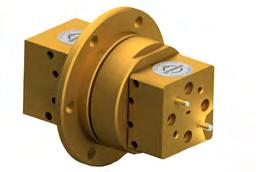
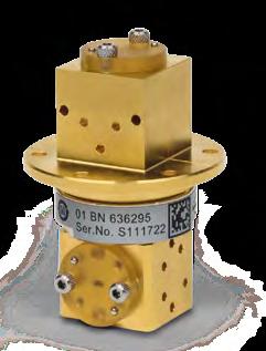
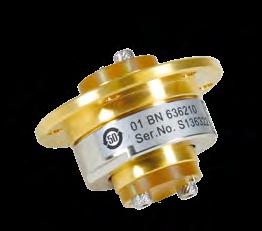
Interface Styles
The interfaces are available in I, U and L styles. These differ in the orientation of the input and output connections of a rotary joint (at the rotor and stator).
In the I style, both are aligned with the rotational axis, in the U style both are perpendicular to the rotational axis, and in the L style one is perpendicular to the axis while the other is aligned with it.
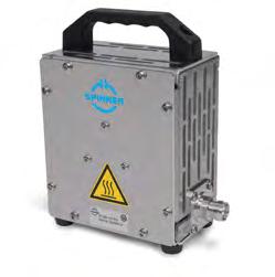
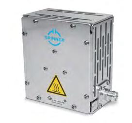
Passive intermodulation (IM3) @ 2 x 20 W Max. ≤-165 dBc; typ. ≤-170 dBc
Average power capability Max. 50 W
Dimensions (L x W x H) 150 mm x 91.5 mm x 170 mm
Weight ≈ 3.0 kg
Maximum surface temperature 50°C
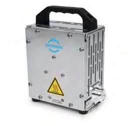
Switches
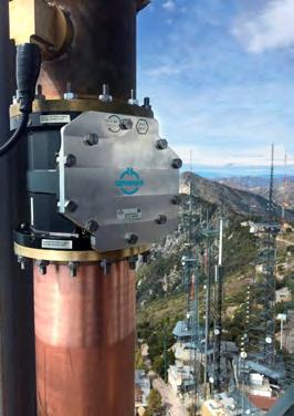
Automate mobile radio antenna testing with SPINNER low-PIM switches for up to 6 GHz!
A surprisingly large share of low-PIM RF component testing is still done manually. But there is enormous potential for reducing both labor and costs.
Although very similar approaches are taken for testing many products, many companies still aren’t fully tapping the available possibilities for streamlining them. For example, almost all manufacturers still use mobile radio antennas and radio units to measure VSWR and PIM. The methods they work with are quite similar, but practically without exception they involve laboriously inserting individual devices and cables between the objects being tested and the measurement equipment.
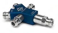
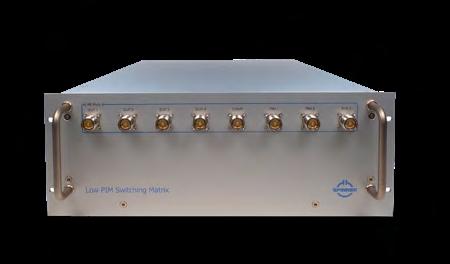
The newly developed SPINNER low-PIM switch has great potential for boosting the efficiency of testing. Technically it’s a double-pole, double-through (DPDT) crossover switch, also known as a switching matrix, with two inputs that are switched through to two outputs. It’s excellently suited for measuring VSWR and PIM, since it eliminates the need to
laboriously disconnect and reconnect the test setup for each object. Plus, if multiple adapters and lines have been used they can either be eliminated completely or deployed more efficiently elsewhere. After each measurement, it’s only necessary to throw the switch to continue testing with different settings or devices. And if multiple tests need to be performed at the same time, a switching matrix can be assembled to operate several switches at once, depending on the required test path, and perform multiple measurements simultaneously.
These extremely low-PIM switches feature a service life of about 500,000 cycles and are specified for -165 dBc (typ. -170 dBc). They are available with 7-16 or 4.3-10 connectors for frequencies up to 3.8 GHz. We’re now also offering a new version with 4.3-10 connectors for up to 6 GHz.
Tests have shown that costs can be slashed by up to 80% by using switches and switching matrices, depending on how they’re configured.
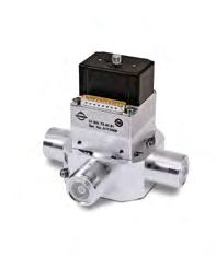
PIM
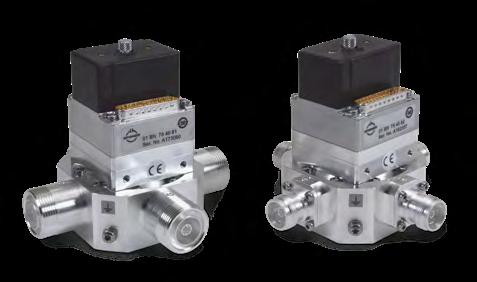
Coaxial 2-Way Switches up to 3.8 GHz
Lowest intermodulation
Maximum phase and amplitude stability
Fast switching
Hot switching
Guaranteed cycles
Cascadable
Suitable for calibrated setup
Part Number BN 754081 7-16 female BN 754082 4.3-10 female
Passive intermodulation (IM3) @ 2 x 20 W
Max. ≤-165 dBc; typ. ≤-168 dBc
Switching time 100 ms
Switching frequency Max. 30 operations per minute
Service life
View Video
RF Test: Switching between VSWR and PIM using SPINNER‘s low PIM switch/EasyDock
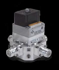
Coaxial 2-Way Switch up to 6 GHz
Part Number
Passive intermodulation (IM3) @ 2 x 20 W
Switching time
Lowest intermodulation
Highest phase and amplitude stability
Fast switching
Hot switching
Guaranteed cycles
Cascadable
Suitable for calibrated setup
≤-165 dBc; typ. ≤-168 dBc
Switching frequency Max. 30 operations per minute Service
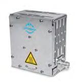
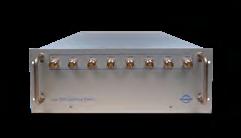
Switching Matrix – Low IM, 8 In / 8 Out up to 3.8 GHz
Contactless switching
Lowest intermodulation
Maximum phase and amplitude stability
Fast switching
Hot switching
Guaranteed cycles
Cascadable
Part Number On request
Interface type (16 connections) 4.3-10-f (50 Ω) per IEC 61169-54
Passive intermodulation (IM3) @ 2 x 20 W Max. ≤-155 dBc; typ. ≤-165 dBc
Switching time 100 ms
Switching frequency Max. 30 operations per minute
Life Min. 500,000 cycles
Dimensions (L x W x H) 666 mm x 482.6 mm x 443.7 mm
Weight ≈ 40 kg
Control interface
More information available on request
Controlled via USB Ethernet Other protocols on request
Figure similar
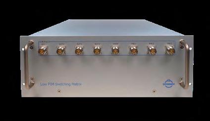
Switching Matrix – Low IM, 8 In / 8 Out up to 6 GHz
Contactless switching
Lowest intermodulation
Maximum phase- and amplitude stability
Fast switching Hot switching
Guaranteed cycles
Cascadable
Part Number On request
Interface type (16 connections) 4.3-10-f (50 Ω) per IEC 61169-54 Characteristic
Passive intermodulation (IM3) @ 2 x 20 W Max. ≤-155 dBc; typ. ≤-165 dBc
Switching time 100 ms
Switching frequency Max. 30 operations per minute
Life Min. 500,000 cycles
Dimensions (L x W x H) 666 mm x 482.6 mm x 443.7 mm
Weight ≈ 40 kg
Control interface
More information available on request
Controlled via USB Ethernet Other protocols on request
Figure similar
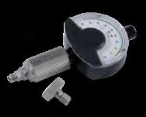
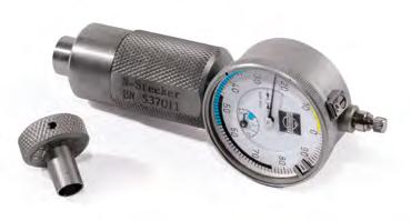
Connector Gauges
Why use a gauge?
Proven RF measurement procedures require that all coaxial connectors on equipment, cables and terminations be routinely measured to detect mechanical tolerance variations that could affect electrical performance or damage the connector. When using coaxial cables, it is particularly important for them to be tested before use to ensure that the assembled connector conforms to the relevant mechanical specification limits. There is otherwise a risk of damage to the calibration components, which would in turn result in costly downtimes and repairs. Coaxial connectors should never be forced together when making a connection, since the apparent need to do so often indicates that they are defective, damaged, or incompatible.
BN 537015 7-16 male
BN 537037 7-16 female
BN 533315 4.3-10 male, inner conductor
BN 533317 4.3-10 female, inner conductor
BN 533318 4.3-10 female, outer conductor
BN 537011 Type N 50 Ohm male
BN 537013 Type N 50 Ohm female
BN 537074 3.5 mm male
BN 537075 3.5 mm female
BN 537081 2.92 mm male
BN 537082 2.92 mm female
BN 537078 2.4 mm male
BN 537079 2.4 mm female
BN 537083 1.85 mm male
BN 537084 1.85 mm female
BN 534940 1.35 mm male
BN 534941 1.35 mm female
BN 537085 1.0 mm male
BN 537086 1.0 mm female
BN 530815 0.8 mm male
BN 530816 0.8 mm female
Designed to properly gage the contact pin locations and pin depth of used Interfaces
Marked tolerance limits for different connector grades
Calibration standard to adjust to zero
Certain dimensions are critical for the mechanical integrity, non-destructive mating and electrical performance of the connector. The mating face is usually offset from the reference plane. This is done to reduce mechanical damage or isalignment when making connections.
On a SPINNER connector gauge, the tolerance limits for the various connector standards are color-coded on the dial. This makes a good/bad assessment of the gauge dimensions of precision connectors easy even without in-depth knowledge of the standard. A so-called reference gauge for monitoring and calibrating the connector gauge is included in the scope of delivery.
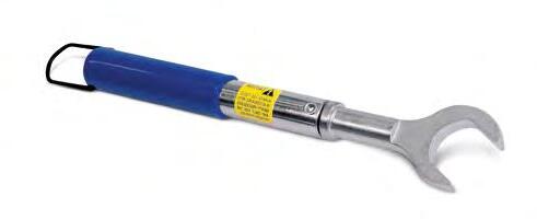
Torque Wrenches "'" SPINNER '--'
Properly tightening connectors improves every calibration and subsequent measurement.
Why use a torque wrench?
RF torque wrenches are designed to help prevent excessive tightening of the coupling nut of the sensitive coaxial precision connectors. The international standards specify a maximum tightening torque for each precision connector size, which must not be exceeded. These torque values differ considerably from those of the standard connectors. The user must therefore ensure that the correct torque value is applied to the connector.
SPINNER torque wrenches for precision connectors are therefore already preset to the correct torque. However, this alone is not enough for torque-controlled screwing with high accuracy. Even when using a torque wrench, both sides of the connector can be damaged if,
Different types of torque wrenches
Preset with the precise torque needed for 0.8 mm, 1.0 mm, 1.35 mm, 1.85 mm, 2.4 mm, 2.92 mm, 3.5 mm and Type N Interfaces
8 mm version with soft pads on spanner flats avoiding scratches on precision connector surfaces
Additional open-ended wrench included in set BN 238741
for example, the connector covered by the coupling nut rotates unintentionally. To prevent this, the connector should be additionally held in its initial position with a simple open-ended wrench.
When the set torque value is reached, this is indicated by a clearly audible clicking of the torque wrench. From this point on, no further force should be applied. It is also not necessary to repeat the tightening process. Torque wrenches for precision applications should be checked or calibrated regularly. An interval of 12 months is recommended. This service can be requested from our aftersales service center.
There are different types of torque wrenches, including "click-type" and "break-over" torque wrenches. Here are the main differences between these two types:
1. Operation:
Click-Type Torque Wrench
A click-type torque wrench has a mechanism that produces a noticeable "click" sound and a slight release in the handle when the preset torque is reached. This sound and release signal to the user that the desired torque has been achieved. The mechanism often involves a spring-loaded ratchet that snaps over a point to produce the click.
2. Accuracy:
Click-Type Torque Wrench
Click-type torque wrenches are typically very accurate and allow precise control of the torque. They need regular calibration to maintain their accuracy.
3. Application:
Click-Type Torque Wrench
Due to their precise control and clear feedback, they are commonly used in the RF industry and other fields where precise tightening of fasteners is important.l
Break-Over Torque Wrench
A break-over torque wrench operates with a hinge mechanism. When the preset torque is reached, the wrench collapsed at the joint, indicating to the user to stop turning. This collapsing action is often less audible than the click of a ratchet-type wrench but is still noticeable.
Break-Over Torque Wrench
Break-over torque wrenches are also very accurate, but the feedback can be subtler than with click-type wrenches. They provide a reliable method of torque control and also require regular calibration.
Break-Over Torque Wrench
These wrenches are used in various industries, including RF industry, especially where a less dramatic feedback is preferred, or employees in the laboratory should not be acoustically disturbed by others using a click torque wrench.
Torque Wrenches
Summary of Differences:
Feedback:
Click-type torque wrenches provide audible and tactile feedback (“click”), while break-over torque wrenches indicate the torque is reached through a noticeable folding or collapsing in the middle part of the hand grip.
Mechanism:
Click-type wrenches use a spring-loaded ratchet mechanism, while break-over wrenches use a hinge mechanism.
Torque Wrenches – Click-Type
Torque Wrenches – Break-Over-Type
Usage:
Both types are used in similar fields; the choice often depends on user preference for the type of feedback.
Both types of torque wrenches are valuable tools, and the choice between them can be based on the specific application and the user’s preference for feedback type.
Accessories for Torque Wrenches
Part NumberDescription
A45535 Spare soft pads for torque Wrench BN 238741
SPINNER designs and builds cutting-edge radio frequency systems, setting performance and longevity standards for others to follow. The company's track record of innovation dates back to 1946, and many of today's mainstream products are rooted in SPINNER inventions.
Industry leaders continue to count on SPINNER's engineering excellence to drive down their costs of service and ownership with premium-quality, off-the-shelf products and custom solutions. Headquartered in Munich, Germany, the global frontrunner in RF components remains the first choice in simple-yet-smart RF solutions. www.spinner-group.com