Allcableassembliesarebuilttocustomerspeci昀椀cations usingthemostadvancedequipmentandprocedures includingIPC-WHMA-A-620trainedtechniciansforsoldering. AllassembliesaretestedforVSWRandinsertionlossbefore leavingthefactory.Phasematching,amplitudematching, andtimedelaymeasurementsupto67GHzareavailable when required.
Wecanprovideeitherin-houseoranexternallaboratory forenvironmentaltestingsuchashumidity,saltspray, vibration,thermalshock,昀氀extesting,aswellasotherunique requirements.Engineeringsupportisalsoavailablefor optimalcable/connectorcon昀椀gurationinracksystems, blackboxes,andotherpackagingareaswheretransmission line performance is critical to the overall system performance.
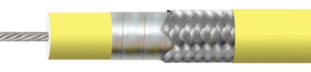
IW-MicrowaveProductsDivision’sextremelyLowLossCable Assemblies are optimized for operation in their respective frequencybandsfromlowMHzto67GHz.Uponrequest we have the ability to accommodate custom assembly con昀椀gurations,andcanextrudeabroadrangeofjacketing materials.Ourjacketingcapabilitiesallowustoproduce assembliesthathaveextra昀氀exibility,extended昀氀exlife,low andhightemperatureranges,andresistancetooilsand corrosive materials.
OurstandardassembliesareextrudedwithFEP.Hereisalist of other materials that are available but not limited to:
CABLE ASSEMBLIES
IW’s extremely low loss cable assemblies are optimized for operation in their respective frequency bands from the low MHz to 110 GHz. Upon request we have the ability to accommodatecustomassemblycon昀椀gurations,andcan extrudeabroadrangeofjacketingmaterials.
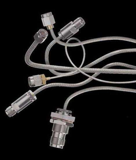
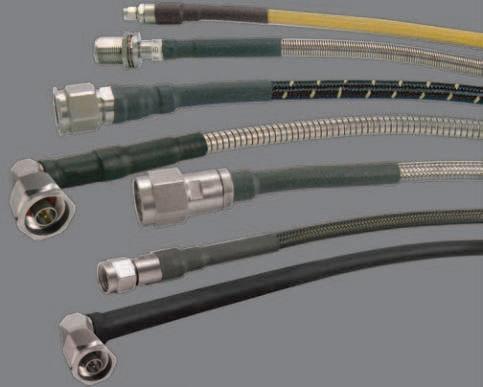
AllofIW’scoaxialcablesareavailableas昀椀nishedassemblies, includingpartiallyterminatedcables,fullyterminated,plus phase or time delay and offset matched sets.
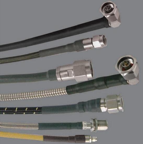
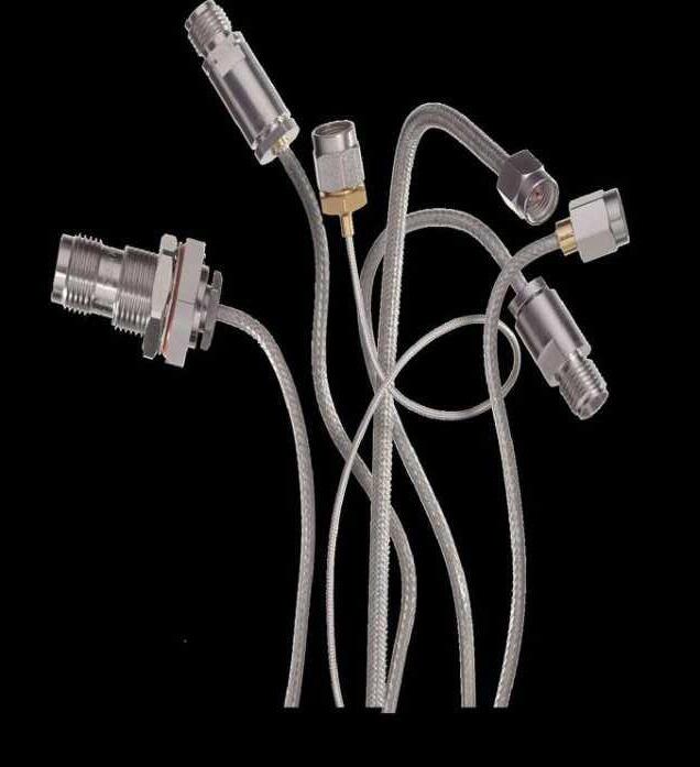
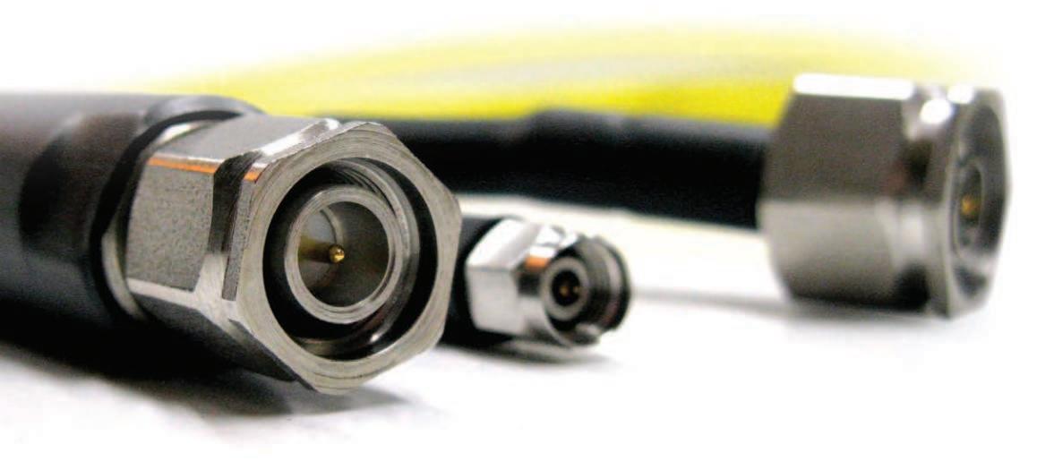
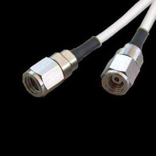
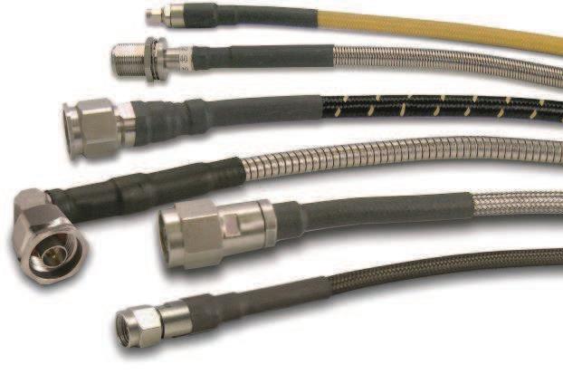
Withawiderangeofinterconnectproductsavailable,we’re abletooffercustomcableassemblylengthsfromafewinches to 100ft and above to suit your application. We offer a variety ofconnectorsincludingSMA,TNCA,N-type,3.5mm,2.92mm, 1.85mminstraight,rightangle,maleandfemale,with bulkheadandfour-hole昀氀angemountingoptionsavailable onsomedesigns.
AllconnectorsaredesignedtomeettherequirementsofMILPRF-39012withinterfacescomplianttoMIL-STD-348.Our stainlesssteeldesignsensureperformanceto18GHzforSMA, TNCA,andN-type,withrightanglepartsusingsweptcenter contacts to ensure optimum performance.
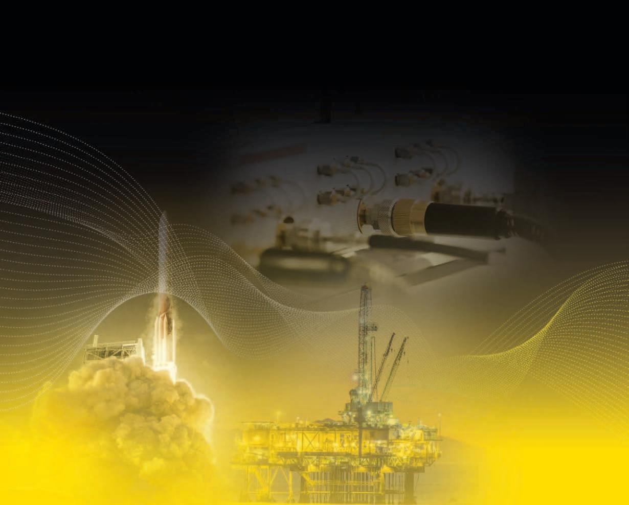
IW serves a broad range of both military and commercial markets. These include telecommunications, data links, satellite systems, airborne electronic warfare and counter measures, missile systems, UAV applications, avionics and instrumentation, 昀椀re control systems, medical electronics, and geophysical exploration.
We’re how the microwave industry gets connected!
Aerospace
Sub-Surface
SatCom
Missiles
Ground
Vehicles
High
Tactical
CIWS UAVs
Medical Electronics
ECMs
Geothermal Exploration
Instrumentation
High End Broadcast Telecommunications
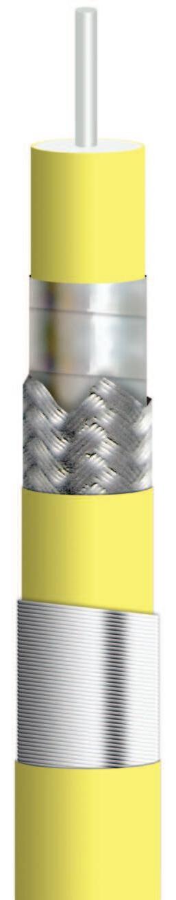
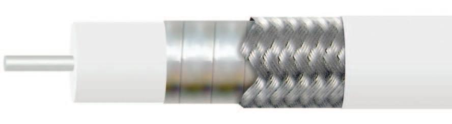
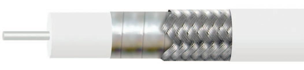
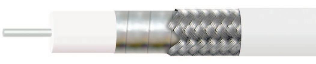
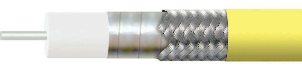
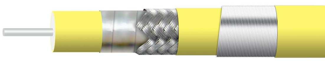
CABLE CONSTRUCTION
TAILORED TO YOUR SPECIFICATIONS
IW is ready to work with you to provide the exact cable speci昀椀cations you need for your extreme condition application. We start at square one, from initial speci昀椀cations and requirements analysis; through the design phase using CAD, working with your systems and applications personnel; then through development, manufacturing and delivery; right up to hands on guidance for installation andmaintenance.
The needs of each of our microwave customers are diverse and demanding and can change on a moment’s notice. That’s why we never rest on our laurels.
We are constantly working to develop the next new innovative machine, or to design the newest process for delivering state of the art microwave cables and assemblies.
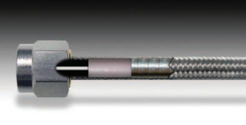
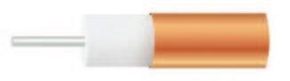
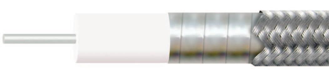
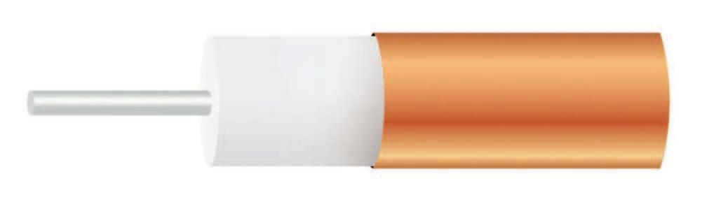
These scale drawings (approximately 50X actual size) illustrate IW’s unique Multi-Ply Laminate insulation that eliminates the problems which occur with other forms of construction.
Extruded Insulation requires a thicker insulating wall to compensate for the possibility of conductor eccentricity within the insulation.
Lap Wrap Tape Insulation creates an irregular surface which precludes use with “O” ring seals at high pressures; contamination on the tape surface creates a low resistance path; and a corona site forms in the triangular voids created where the tape overlaps.
1 2 3
IW’s Multi-Ply Laminate
Insulation, by contrast, delivers greater reliability with maximum space and weight savings.
PTFE Type F-6
PTFE Type F-2
materials per ASTM D 4894
B-298.
per ASTM-B-33
Flammability Test
CABLE CONSTRUCTION - AN OVERVIEW
Upon request we have the ability to accommodate custom assembly con昀椀gurations, and can extrude a broad range of jacketing materials.
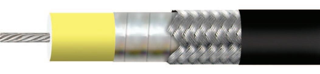
Our jacketing capabilities allow us to produce assemblies that have extra 昀氀exibility, extended 昀氀ex life, low and high temperature ranges, and resistance to oils and corrosive materials. Our standard assemblies are extruded with FEP.
Other materials available include:: FEP
ETFE - Max temp range 200º C
Low Smoke/Zero Halogen TPU
Max. Temp 90º C
Santoprene - Max temp range 135º C
Below is an overview of our standard product selection, but as you peruse our catalog you can see we can offer you and your company a vast amount of options.
CABLE SPECIFICATIONS
CABLE CONSTRUCTION - AN OVERVIEW (continued)
CABLE CAPABILITIES - OVERVIEW
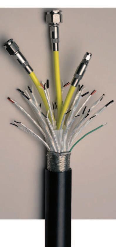
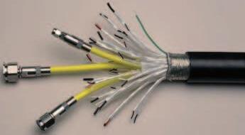
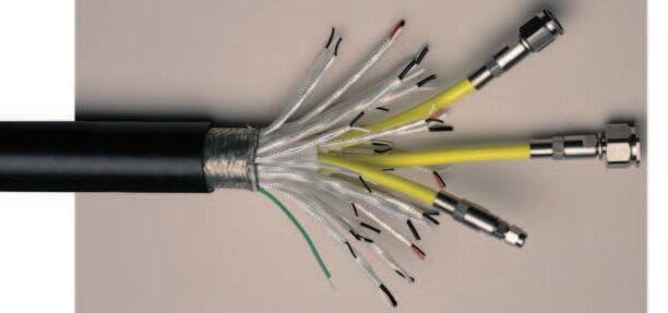
IW Microwave Products has the capability to supply composite RF & microwave assemblies for various applications including marine platforms such as submarines. One example is a multicable type assembly which includes twisted pair, twisted triple, 16AWG and custom coaxial cable.
All cable products are designed and manufactured at the Insulated Wire Headquarters facility at Bayport, NY, with the coaxial connectors and cable assemblies prepared at the Microwave Products location, located close by at Ronkonkoma, NY.
MECHANICAL CONSTRUCTION
IW’s composite cables provide a myriad of options. Components can include individually shielded and jacketed signal transmission cables, power cables, microwave cables and 昀椀ber optic. Depending on the application, cables can be optimized to address issues such as hydrostatic pressure, tensile loads, concentrated compression points, etc. Overall shielding can be provided with ferrous or nonferrous materials. High performance, non-metallic braids and strength members, such as Kevlar™ are also available.
The cable shown here was produced for a submarine application and contains multiple, individual signal cables and IW’s Tuf-Flex™ microwave cables for use at frequencies up to 18 GHz. Water block 昀椀llers and binders are incorporated under a double braided Sn/Cu braid and polyurethane jacket. Cable withstands the anticipated environmental extremes in accordance with the method requirements of MIL-DTL24643B par 4.8.8 and can withstand hydrostatic pressure up to 1050 psi.
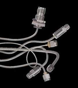
IW provides hands on service to install and troubleshoot cabling, like this complex wire created for the US Navy.
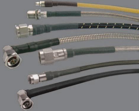
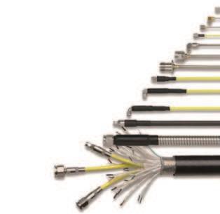
PRODUCT RANGE - OVERVIEW
Our product range of coaxial cables are designed to meet IW speci昀椀cations for high performance across the electromagnetic spectrum to 150 GHz.
All of IW’s coaxial cables are available as 昀椀nished assemblies, including partially terminated cables, fully terminated, plus phase or time delay and offset matched sets.
Offering optional Protection Microwave transmission lines are quite often exposed to a wide range of hostile environments. These may include extreme temperature, abrasion, comprehensive forces, high pressure 昀氀uids, solvents, chemicals, salt water, UV, vibration, and mechanical stress, just to name a few.
Insulated Wire has the capability to supply composite RF & microwave assemblies for various applications. With complete control of the manufacturing process, IW is able to offer custom solutions based on standard process and product for many types of applications.
To provide improved electrical and mechanical performance over traditional hand-formable designs, Insulated Wire presents Re-Flex™.
Insulated Wire now offers four line sizes of 75Ω cables utilizing the same technology and materials that give our 50Ω products industry leading attenuation performance.
CABLE ATTENUATION
CABLE SPECIFICATIONS
0341
ELECTRICAL CHARACTERISTICS
Impedance 50+/–2Ω
CutOffFrequency(cableonly,max) 150GHz
Capacitance 28.6pF/ft.
VelocityofPropagation 71%
TimeDelay 1.43ns/ft.
ShieldingEffectivenessupto18GHz >90dB
CableAttenuationFactors* K1=53,K2=0.90
PowerHandling SeeChart
MECHANICAL CHARACTERISTICS
Weight
StaticBendRadius
0.064oz/ft(5.95g/m)
0.2”(5.1mm)
DynamicBendRadius 0.375”(9.5mm)
ENVIRONMENTAL CHARACTERISTICS
OperatingTemperatureRange -65°Cto+150°C
RoHS3(EU2015/863) Yes
*Standardcableassemblytemperaturerangeis
0471
ELECTRICAL CHARACTERISTICS
Impedance 50+/–2Ω
CutOffFrequency(cableonly,max) 110 GHz
Capacitance 28.6pF/ft
VelocityofPropagation 71%
TimeDelay 1.43ns/ft.
ShieldingEffectivenessupto18GHz >90dB
CableAttenuationFactors* K1=37.5,K2=0.935
PowerHandling SeeChart
MECHANICAL CHARACTERISTICS
Weight
StaticBendRadius
DynamicBendRadius
ENVIRONMENTAL CHARACTERISTICS
0.08oz/ft(7.4g/m)
0.2”(5.1mm)
0.375”(9.5mm)
OperatingTemperatureRange -65°Cto+150°C
RoHS3(EU2015/863) Yes
*Standardcableassemblytemperaturerangeis
ELECTRICAL CHARACTERISTICS
Impedance
ShieldingEffectivenessupto18GHz
CableAttenuationFactors(K1,K2)*
PowerHandling SeeChart SeeChart
MECHANICAL CHARACTERISTICS
ENVIRONMENTAL CHARACTERISTICS
OperatingTemperatureRange
RoHS3(EU2015/863) Yes Yes
1 Standardcableassemblytemperaturerangeis -55°C to +165°C, -65°C
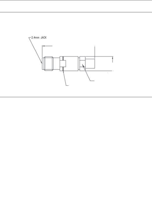
CONNECTORS FOR 280 SERIESCONNECTORS FOR 280 SERIES
ELECTRICAL CHARACTERISTICS
Impedance 50+/–2Ω
CutOffFrequency(cableonly,max) 11.3GHz
ShieldingEffectivenessupto18GHz >90dB
CableAttenuationFactors* K1=2.9,K2=0.179
PowerHandling SeeChart
MECHANICAL CHARACTERISTICS
ENVIRONMENTAL CHARACTERISTICS
OperatingTemperatureRange
1 Standardcableassemblytemperaturerangeis
CABLE ATTENUATION
CABLE SPECIFICATIONS
CableAttenuationFactors* K1=1.9,K2=0.183
PowerHandling SeeChart
OperatingTemperatureRange -65ºCto+135ºC
RoHS3(EU2015/863) Yes
(cableonly)
75 Ω PRODUCTS 75 Ω SERIES
Insulated Wire now offers three line sizes of 75Ω cables utilizing the same technology and materials that give our 50Ω products industry leading performance.
OptionalprotectionforOutsideBroadcast applicationsincludeLowSmoke/ZeroHalogen polyurethane jacketing to provide weather-proo昀椀ng, andarmoringoptionstopreventdamagedueto accidentaldamage.
1151-75: Small diameter cable providing lower loss than RG179 with an 0.085” line size. BNC and HD BNC connectors are available, performing up to 18 GHz.
1601-75: Mid-size cable providing loss comparable to RG59 with superior shielding performance in an 0.141” line size and performing up to 18 GHz.
1801-75: Mid-size cable offering exceptional attenuation with Precision N and BNC connectors for applications where commodity cables cannot provide the performance required by increasing signal speeds; 1801-75 has been tested to 18 GHz.
2801-75: Introduced to out-perform RG11 both electrically and mechanically. IW 280 series cable is a more 昀氀exible solution, intended to provide optimum attenuation performance to 18 GHz.
CABLE ATTENUATION
To provide improved electrical and mechanical performance over traditional hand-formable designs, Insulated Wire presents Re-Flex™.
Available in 0.085”, 0.141”, 0.235” and 0.325” diameters (identi昀椀ed as RF085, RF141, RF250 and RF325), IW’s RF cable series offers the advantages of the same lamination process used on our Low Loss products. Combined with the same double shield construction plus a solder-free tin/alloy plated outer braid, the Re-Flex™ design provides a re-formable cable that will not develop micro fractures with repeated 昀氀exing, eliminating manufacturability issues associated with conformable style RG cables.
Both RF085 and RF141 are industry standard line sizes, consequently a wide range of connector types and styles can be used with these cables, including: SMA, TNC, N, SMP, SMPM, 2.92mm/K™, 2.4mm and 1.85mm/V™, with performance up to 60GHz. RF250 is commonly used for higher power applications with SMA, TNC, N, SC and HN connectors available.
Re-Flex™ assemblies can be employed wherever a semi-rigid or conformable cable type is currently used, and with FEP™ jacket available as a standard option, Re-Flex™ provides greater versatility. Cable part numbers are TPRFEP085, TPRFEP141 and TPRFEP250.
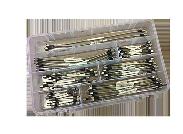
RE-FORMABLE CABLE ASSEMBLY SOLUTIONS STRAIGHT OUT OF THE BOX!
For customers who know the advantages of Re-Flex over traditional hand-formable and semi-rigid, and to make cable selection easier for those new to our product, IW is pleased to announce our new range of Re-Flex Starter Kits!
Three kits are currently available:
CT-1879 (SPSD-TPRF085-XXX-SPSD) direct solder
SMA male/male using TPRF085 (RG405 line size)
CT-1880 (SPSD-TPRF141-XXX-SPSD) direct solder
SMA male/male using TPRF141 (RG402 line size)
Each kit comprises seven different assembly lengths 3”, 4”, 5”, 6”, 8”, 9” and 12” 5 pcs of each, providing the design engineer with a convenient aid for performing cable routing in prototype system builds
RF085 Yes
RF141 Yes Yes
RF250 Yes Yes
SMA(m)toSMA(m)directsolder,3”andup
SMA(m)toSMA(m)directsolder,3”andup
SMA(m)toSMA(m)shellstyle,2”andup
CT-1881 (SPSH-TPRF141-XXX-SPSH) shell style SMA
using TPRF141 (RG402 line size)
The ability to continually re-form Re-Flex without the need for custom tooling to shape the cable, and the elimination of debris caused by micro fracturing is a key feature of the Re-Flex cable design, and enables the designer to make signal path/layout changes without having to throw product away after using it once.
Available as bare copper or plated with tin, tin-lead, or silver. *Attenuation= K1
(cableonly)
ATTENUATION (MAX)
CONNECTOR OPTIONS CONNECTOR OPTIONS
This catalog lists the most common con昀椀gurations for each cable type. If necessary, IW can modify existing designs or design a custom connector to meet your speci昀椀c requirements.
Our standard connectors meet the environmental speci昀椀cations of MIL-PRF-39012. Our N, TNCA and SMA connectors are optimized to be 18 GHz, all others meet applicable industry standards.
Connector types listed are preferred matching for referenced cables. Additional connector types can be provided. Please consult factory.
A Stainless steel 昀氀exible armor
N Black neoprene jacket
NX Nomex
LC Low smoke / zero halogen polyurethane
† LC–LS/ZHjacketisavailablefor140-480 seriescables,including03/06/08;not recommendedforReFlex™.LCjacketcan be combined with external armor code ‘A’ for maximum crush resistance in outdoor environments.
With so many variables involved in creating custom wires for multiple purposes, IW has devised an Part Number (P/N) Coding System which we use to readily identify all our microwavecables.
J R 2 P S
ASSEMBLY LENGTH DEFINITION
The outlines below show typical cable assembly con昀椀gurations and reference points to determine overall length.
Microwave transmission lines are quite often exposed to a wide range of hostile environments. These may include extreme temperature, abrasion, comprehensive forces, high pressure 昀氀uids, solvents, chemicals, salt water, UV, vibration, and mechanical stress, just to name a few.
CUSTOMSOLUTIONS
In addition to our internally ruggedized cables, IW has a wide range of materials and processes designed to protect the integrity of our cable assemblies. These include a variety of metallic and non-metallic external sheaths to address your speci昀椀c application. Please contact us for details.
of Chemours Company FC, LLC
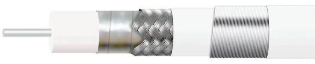
TUF-FLEX™ CABLE PERFORMANCE
IW’s range of Tuf-Flex™ cables was introduced to provide a high level of crush resistance for applications where an unarmored cable could be subject to damage, e.g. long assemblies used in a test chamber; down-mast, air frame, etc. where a cable needs to be secured in position and could be subject to high levels of vibration.
The following tables show the results of crush and bend tests performed on IW’s Tuf-Flex™ internally ruggedized cable. The test samples were 2ft. overall length, using 1803 cable.
Results show maximum VSWR and Insertion Loss, tested across a frequency range of 40 MHz to 18 GHz. The test sample was placed between two 1” diameter plates with the force applied to the top plate.
Theservingusedtocreatethearmornotonlyprovides excellentcrushresistance,butmaintainstheconcentricity ofthecableasitis昀氀exedthrougharadius,enablingRF performance to be maintained.
For applications where phase or electrical length is a critical performance parameter, IW can provide matched assembly sets, tested to customer speci昀椀cations, typically up to 40 GHz, with both Low Loss Phase Stable and Re-Flex™ cable types.
Relative phase matching is a common requirement achieved with multiple assembly sets. Typical phase matching tolerances are shown in Table 1 below.
Tighter tolerances may be achievable; IW engineers review all matching requirements on a case by case basis.
In addition, IW also provides time delay matched assemblies with tolerances in the order of 2pS being achievable with both Low Loss and Re-Flex™ cable types, and individual assemblies can also be supplied trimmed to a speci昀椀c electrical length.
All matched assemblies are tested 100% for insertion loss and VSWR performance parameters in addition to phase.
The following contains a list of precautions and procedures that should be taken when handling or installing Insulated Wire cable assemblies. They should be used as guidelines and followed whenever possible. By doing this you can ensure a long assembly life which requires virtually no maintenance.
LIMIT BEND RADIUS WHENEVER POSSIBLE
AlthoughIWcableassembliescan accommodate a very small bend radius,itisrecommendedtouse thewidestpossibleradiusto昀椀tthe application.Thiswillhelptokeep mechanicalstresseslowthrough thebendandprolongthelifeofthe assembly.
AVOID PULLING AN ASSEMBLY THROUGH CHANNELING BY THE CONNECTOR END TERMINATION
IWcableassembliesaredesigned tooperateatthehighestelectrical performancelevel.Highperformance cables such as these require special handlingprocedurestoensure optimum electrical performance. Manyofthesehandlingprocedures areoutlinedindetail,howevertaking justafewbasicpreventativemeasures duringhandlingcansigni昀椀cantly extendthelifeoftheassembly.You shouldalwaystakecaretoprevent anythingfrombeingplacedonan assembly.Thiscouldresultininternal damagecausedbycompression.Also, preventthecablefrombendingbelow it’s minimum bend radius as this will causethecabletokink,whichresults ininternaldamageandsubsequent degradationinRFperfomance.
AVOID TORQUING DOWN CONNECTOR ENDS UNTIL BOTH CONNECTORS ARE
Itisimportantto昀椀rsthandtighten both connectors into position before any torque is applied. If a connector is torqued down before the assembly isroutedintoposition,excessive torsion could be applied at the torqued connector’sterminationduringthe routing.Thesetorsionforcescould causethedielectrictochangeits mechanical position at the connector termination.Thiscouldultimatelylead to an electrical failure.
AVOID TWISTING ASSEMBLY TO ORIENT CONNECTORS
Wheninstallingassemblieswithright angleconnectors,donottwistthe cable or connectors to orient with thematingconnectors.Twistingthe assembly could result in mechanically changingthedielectricpositionatthe termination and ultimately lead to an electrical failure. Assemblies should bepurchasedwithaspeci昀椀cconnector offsetangletomatchtheproper matingconnector.Ifanoffsetangle needstobechangedduringassembly installation,properadjustment procedurescanbeobtainedbycalling IW’sTechnicalSupport.
AVOID BENDINGTHE ASSEMBLY AT THE CONNECTOR TERMINATION
A cable assembly should never be bentatthebackoftheconnector. Applyingabendprematurelyatthe endofanassemblyandallowingthe bend to encompass the connector could lead to the build up of excessive cableforcesagainsttheconnectorand throughthebendarea.Theapplied forceswillcausethecabletokink. Electricaldegradationandpossible failure may result.
Neverpullanassemblybyits connectorwhenroutingitthrougha structure,channelingorbuilding.Doing thiscouldmechanicallydamagethe connectortermination.Theassembly should always be pulled by the cable itself.Furthermore,theinstallation shouldbeassistedbypushingthe assemblythroughthechannelingwhile thecableispulled.Additionally,itis less stressful to the assembly if it is installedinphases(throughindividual sections)ratherthanasinglerun acrosstheentireroutinglength.
NEVER ALLOW AN ASSEMBLY TO SUPPORT ITS OWN WEIGHT WHEN ROUTED IN A VERTICAL INSTALLATION
Neverallowanassemblytohang freelybyitsownweight.Clampdown thecableatequalintervalsalongits length.Cablehangerscanbeused when it is not possible to clamp down the assembly in a vertical installation provided the assembly has been reinforced for such an installation. Usingmultiplehangerswhenever possible is also recommended to help evenlydistributetheassembly’sweight alongtherun.
Cableassemblylifecanbeincreased byclampingdownthecableafew inches from the connector ends in applications where the cable will be moving(suchasamovingantenna) orwhereahighvibrationcondition exists.Clampingthecabledownatthe cable ends reduces mechanical loads applied to the connector when the cable is moved.
HANDLE CABLE WITH CARE
MATED IN POSITION
AVOID SUBJECTING THE CONNECTOR ENDS TO CABLE AXIAL LOADS
CABLE HANDLING
AVOID THE USE OF CABLE TIES
Mosthighperformancecablesuse anair昀椀lleddielectriccore.This makesthecableverysoft.Therefore any compressive load applied to the cablehasthepotentialofcollapsing the dielectric core within the cable. Cabletiesandtiewrapsarenot recommendedforthisreason.They offer virtually no load distribution andconsequentlyfocusveryhigh compressiveforcesthroughthetied down area. A concentrated force such as this almost always deforms the cable andsigni昀椀cantlydegradesassembly performance.Forbestholdingresults withminimalclampingforces,IW recommendsrubberizedclamps.Be sure to select a clamp that will apply a minimum amount of compression force whilestillofferingthedesiredholding strength.Selectingaclampthatittoo smallcandoasmuchdamagetoan assembly as a cable tie.
WRAP CONNECTORS IN WEATHER PROOFING WHEN INSTALLING OUTSIDE
All cable connections that will be subjectedtorainandsnowshould bewrappedinaweatherproo昀椀ng material.Aselffusingsiliconetapeis recommendtocreateaweathertight seal over the connection. If weather precautionsarenottaken,water willeventuallyworkitswayintothe connectorassemblycausinghigh insertion losses.
PROVIDE ADEQUATE DRIP LOOPS
Always allow for a drip loop in outside applications to prevent water from 昀氀owingdownthecableandonto theconnector.Overtimethewater couldworkitswayintotheconnector assemblycausinghighinsertionlosses.
TAKE EXTRA CARE ON SHORT ASSEMBLIES
TAKE CAUTION BENDING CABLES UNDER 12” IN LENGTH
Always bend assemblies around mandrels whenever possible.
Theuseofmandrelsorwheels willhelptoevenlydistributbending loads applied to the cable. Thisisthepreferredmethodfor bendingcables.
Takecautionwhenbending cables by hand.
Sometimesbendingacableby hand is the only option. In this casethefollowingmethodshould be used:
Return to the center point of the bendandworkinanoutward directionmakingthebenda littletighter.
Continuetoreturntothecenterof thebend,andworkingoutwarduntil the desired bend is reached.
Anassemblythatis12”inlengthand smallercanbeveryrigiddepending onthecabletype.Thecablebecomes rigidbecauseitsinnerandouter conductorsarefully(mechanically) terminated to the cable connectors.
Thecableisterminatedthiswayto yield maximum electrical performance. Unfortunately,itminimizesthebending characteristics of the assembly because the cable is too short to accommodate the total material volume displacement needed for a typicalbend.Often,theminimumbend radius can not be achieved without damagingtheassembly.Therefore, short cables should only be used in applicationswhereslightjogging bendswillbeused.Alongerassembly that uses a service loop should be considered as a replacement for a shortcableinsituationwhereatightor sharp bend is needed.