SIMPLIFICATION IS OUR INNOVATION Visit www.radiall.com for more information EPX® SERIES EN4644 SECTION 1
EPX S Er IES | 1-1 SIMPLIFICATION IS OUR INNOVATON Visit www.radiall.com for more information
Contents INTRODUCTION Introduction 1-3 Disconnect Applications ���������������������������������������������������������������������������������������������������������������������������������������������������������� 1-4 Rack & Panel Applications 1-5 EPX® SERIES Disconnect Connectors ������������������������������������������������������������������������������������������������������������������������������������������������������������ 1-6 Electrical Characteristics 1-6 Mechanical Characteristics ���������������������������������������������������������������������������������������������������������������������������������������������������� 1-6 Environmental Characteristics 1-6 Rack & Panel Connectors ��������������������������������������������������������������������������������������������������������������������������������������������������������� 1-7 Electrical Characteristics 1-7 Mechanical Characteristics ���������������������������������������������������������������������������������������������������������������������������������������������������� 1-7 Environmental Characteristics 1-7 Inserts & Contact ���������������������������������������������������������������������������������������������������������������������������������������������������������������������� 1-8 Electrical Characteristics 1-8 Retention Characteristics ������������������������������������������������������������������������������������������������������������������������������������������������������� 1-9 INSERTS Insert Selection Table 1-10 How to Order EPX® Inserts ���������������������������������������������������������������������������������������������������������������������������������������������������� 1-11 EPX® Insert Arrangements 1-12 to 1-14 CONTACTS Signal & Power Crimp Contacts 1-15 Oversized & Reduced Crimp Barrel Contacts���������������������������������������������������������������������������������������������������������������������� 1-16 Coaxial Crimp Contacts 1-17 Twinax & Triax Crimp Contacts ��������������������������������������������������������������������������������������������������������������������������������������������� 1-18 Quadrax & BMA Crimp Contacts 1-19 LuxCis ® Fiber Optic Contacts ������������������������������������������������������������������������������������������������������������������������������������������������� 1-20 Signal PC Tail Contacts 1-21 Quadrax Size 8 PC Tail Contacts 1-22 Filler Plugs & Sealing Plugs ���������������������������������������������������������������������������������������������������������������������������������������������������� 1-23
Section 1 Table of
1-2 | EPX S Er IES SIMPLIFICATION IS OUR INNOVATION Visit www.radiall.com for more information
Contents Continued DISCONNECT APPLICATION EPXA Product Overview 1-24 EPXB1 Product Overview ������������������������������������������������������������������������������������������������������������������������������������������������������� 1-25 How to Order EPXA & EPXB1 Shell 1-26 How to Order EPXA & EPXB1 Assembly Kit �������������������������������������������������������������������������������������������������������������������������� 1-27 EPXA & EPXB1 Polarization Code ������������������������������������������������������������������������������������������������������������������������������������������ 1-28 Contacts Termination for EPXB1 1-29 EPXA Shell Dimensions ����������������������������������������������������������������������������������������������������������������������������������������������������������� 1-30 EPXB1 Shell Dimensions 1-31 EPXA & EPXB1 Spare Parts ����������������������������������������������������������������������������������������������������������������������������������������������������� 1-32 EPXA & EPXB1 Accessories 1-33 EPXB2 Product Connectors �������������������������������������������������������������������������������������������������������������������������������������������������� 1-34 EPXB2 Product Overview 1-35 EPXB2 Range Overview ��������������������������������������������������������������������������������������������������������������������������������������������������������� 1-36 EPXB2 Latest Innovations 1-37 How to Order EPXB2 Shell ����������������������������������������������������������������������������������������������������������������������������������������������������� 1-38 How to Order EPXB2 Assembly Kit 1-39 EPXB2 Polarization Code �������������������������������������������������������������������������������������������������������������������������������������������������������� 1-40 Contacts Termination for Receptacles 1-41 EPXB2 Alluminum Shell Dimensions 1-42 to 1-43 EPXB2 Composite Shell Dimensions ������������������������������������������������������������������������������������������������������������������������������������� 1-44 EPXB2 Weights 1-45 EPXB2 Accessories ������������������������������������������������������������������������������������������������������������������������������������������������������������������ 1-46 EPXB2 Spare Parts 1-47 Tools ����������������������������������������������������������������������������������������������������������������������������������������������������������������������������������������� 1-48 RACK & PANEL APPLICATION EPXB3 Product Overview ������������������������������������������������������������������������������������������������������������������������������������������������������� 1-49 How to Order EPXB1, B2, B3 & B4 Shell 1-50 How to Order EPXB1, B2, B3 & B4 Assembly Kit for LRM��������������������������������������������������������������������������������������������������� 1-51 EPXB Shell Mounting 1-52 EPXB Polarization Code ���������������������������������������������������������������������������������������������������������������������������������������������������������� 1-53 Contacts Termination for EPXB1, B2, B3 & EPXB4 Plugs 1-54 EPXB1 Shell Dimensions & Panel Cut-Out���������������������������������������������������������������������������������������������������������������������������� 1-55 EPXB2 Shell Dimensions & Panel Cut-Out ��������������������������������������������������������������������������������������������������������������������������� 1-56 EPXB3 Shell Dimensions & Panel Cut-Out 1-57 EPXB4 Shell Dimensions & Panel Cut-Out ��������������������������������������������������������������������������������������������������������������������������� 1-58 Rack & Panel Accessories 1-59 Rack & Panel Tools ������������������������������������������������������������������������������������������������������������������������������������������������������������������ 1-60 EPXB2 Product Overview 1-61 How to Order EPXB2 Shell for LRU ��������������������������������������������������������������������������������������������������������������������������������������� 1-62 How to Order EPXB2 Assembly Kit for LRU 1-63 EPX® Galley ARINC 810 Product Overview ��������������������������������������������������������������������������������������������������������������������������� 1-64 How to Order EPX® Galley Equipment Connector 1-65 Dimensions & Panel Cut-Out ������������������������������������������������������������������������������������������������������������������������������������������������� 1-66 Multigang EPX Connectors 1-67
Section 1 Table of
Introduction
INTRODUCTION
Radiall is recognized in the aerospace and defense industries for offering one of the broadest innovative product portfolios for connector interconnect solutions. The benefit of our experience with ARINC connectors permits Radiall to provide customers with a strong and global solution
The EPX® series offers a wide range of solutions based on two insert sizes with a large variety of shells and contacts. This product range provides an excellent trade-off between the number of available contacts and the space used. The EPX® series is completely modular and expandable�
EPX® connectors are standardized by the EN4644 European standard�
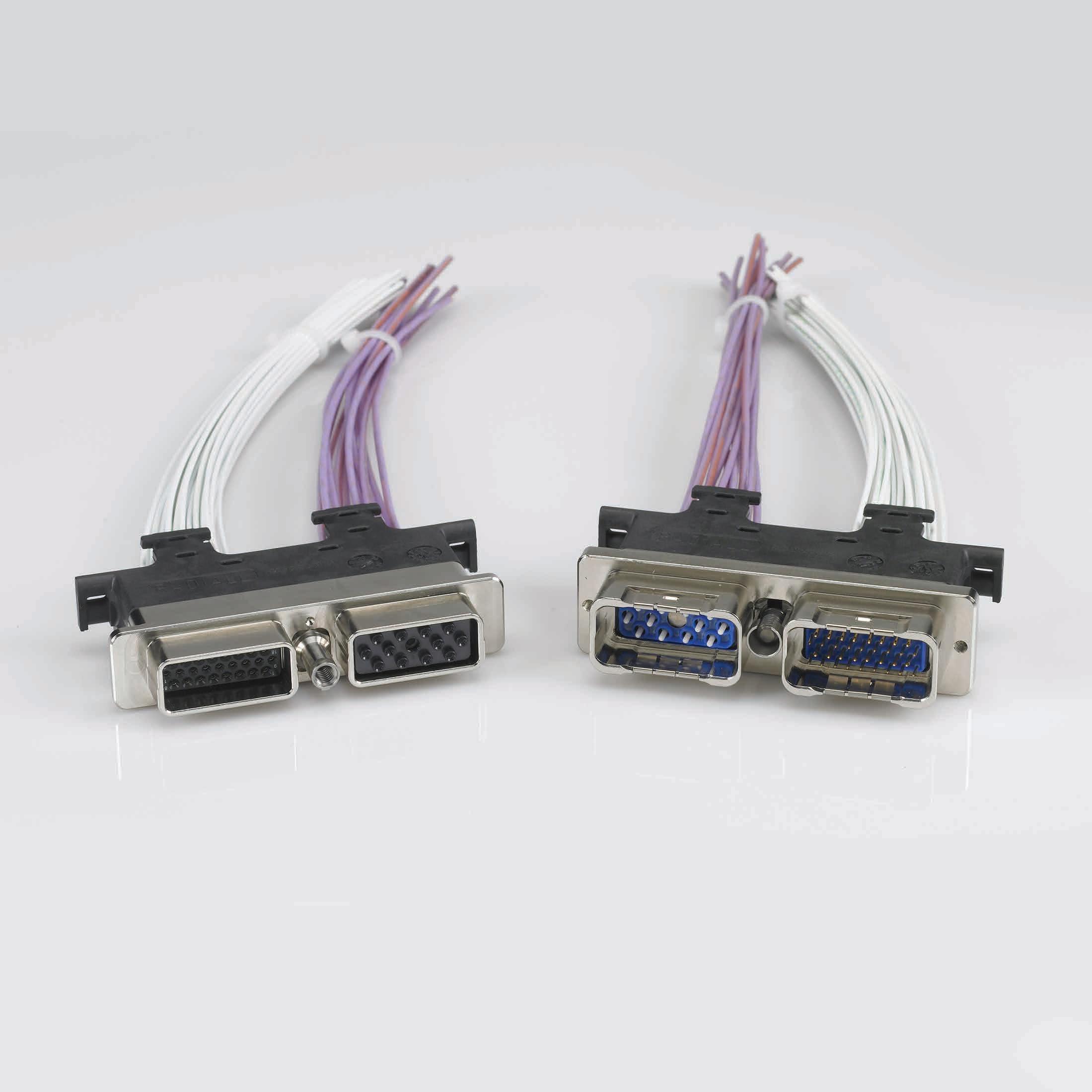
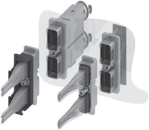
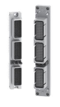
A high-density solution compared to circular connectors:
• Slim shell design with high contact density
• Stackable shells do not require additional space for locking and unlocking the connectors
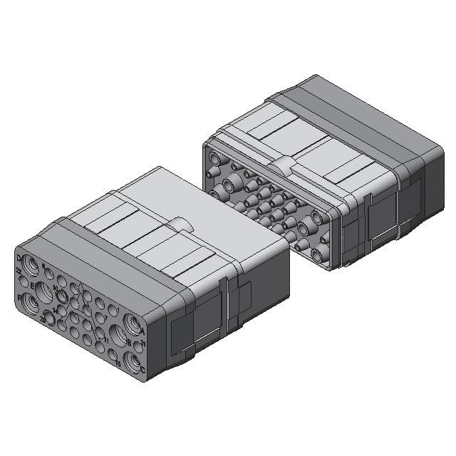
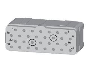
EPXB
5 shells #2 with 2*48 Cts
• Total Cts: 480
• Total surface: 96.90 * 91.80 = 8895.42 mm2
• Gives 18.53 mm2 /contact
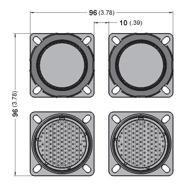
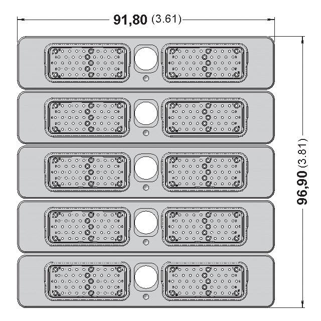
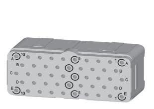
38999
4 shells #23 with 100 Cts
• Total Cts: 400
• Total surface: 96.00 * 96.00 = 9216 mm2
• Gives 23.04 mm2 /contact
A cost saving and user-friendly solution:
• Inserts can be wired in the workshop and later installed in the shells
• A common panel cut-out simplifies the connector installation
• Inserts can be easily installed and removed from the shell
• Inserts and shells are keyed to prevent mis-mating
• Standard Mil spec tools for contact crimping and contact insertion/extraction
• Field replaceable sub-assemblies
• Vibration resistant self-locking threads
A modular concept with a large variety of options:
• Shell can accommodate a wide variety of inserts for signal, power, coax, data bus, fiber optic and high-frequency BMA contacts
• Optional ground blocks (to meet the FAA HIRF requirements)
• Pin and socket inserts can be installed in either plug or receptacle shells (pin contacts are always fitted in the pin insert)
EPX® is a versatile solution available in two different versions:
• Aluminium
• Composite
EPX SEr IES | 1-3 SIMPLIFICATION IS OUR INNOVATION Visit www.radiall.com for more information
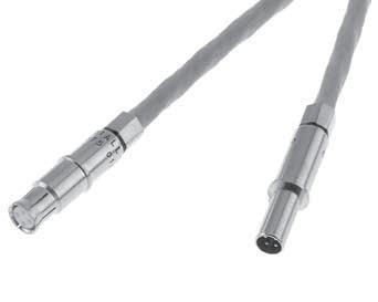
CABLE-CABLE
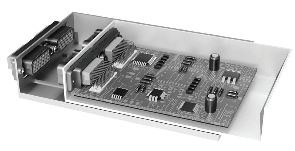
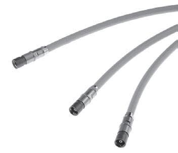
PCB-CABLE
DISCONNECT APPLICATIONS
Specially designed for panel integration on EWIS applications, EPX® disconnect connectors cover cable-tocable and PCB-to-cable links in major commercial and business jet aircrafts.
The connector can be easily identified by the locking device located directly on the connector (quarter turn device for A1 and B1 and central screws for EPXB2)� This disconnect solution offers secure mating while answering OEM’s most stringent requirements, and provides:
• Modularity with three shell sizes: EPXA1, EPXB1 and EPXB2 - available as lightweight shells and compatible with several options such as ground block functionality
EPX® connectors also feature a large variety of inserts and a unique range of contacts covering any technology
EPX® connectors answer all connecting needs with the use of a limited number of components �
• Space savings with the combination of a slim shell design and high density inserts In addition, EPX® disconnect stackable shells do not require additional space to lock and unlock the connectors
• Time savings and cost effectiveness with modular parts that enable pre-wiring Connectors are easy to assemble as the receptacle can be pre-installed Inserts will be wired in the shop and plugged later, which saves integration time
1-4 | EPX SEr IES SIMPLIFICATION IS OUR INNOVATION Visit www.radiall.com for more information Introduction
EPXA1
EPXB1
EPXB2
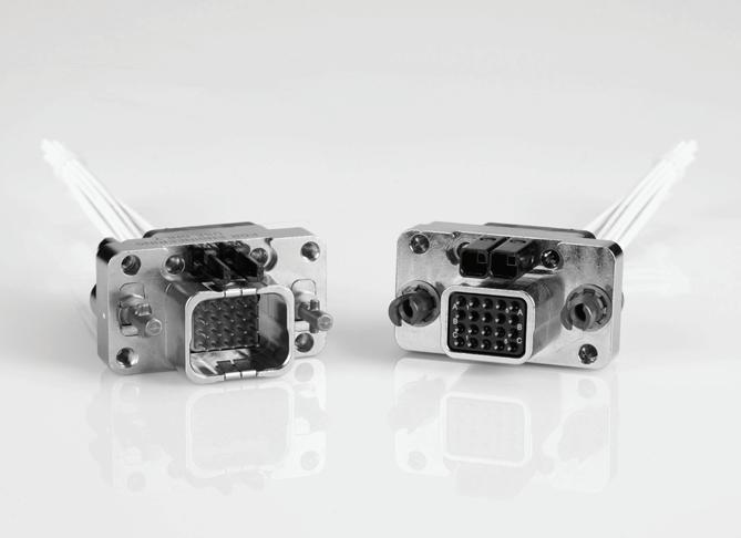
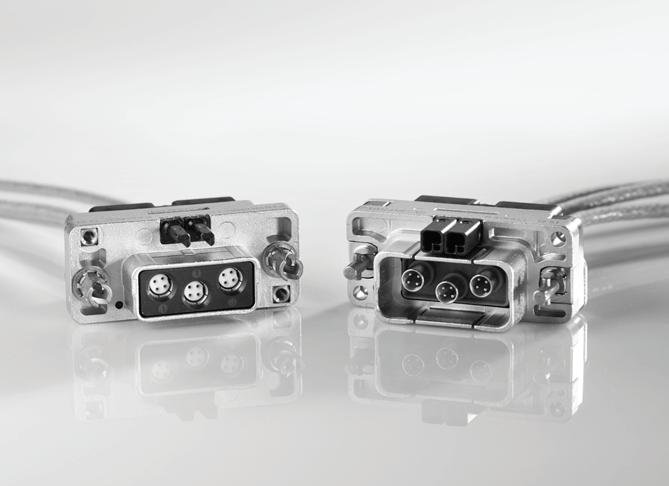
RACK & PANEL APPLICATIONS
In response to the need of system miniaturization and new equipment design, Radiall offers EPX® connector solutions for Line Replaceable Unit (LRU) and Line Replaceable Module (LRM). Discover more about these blind mate connectors:
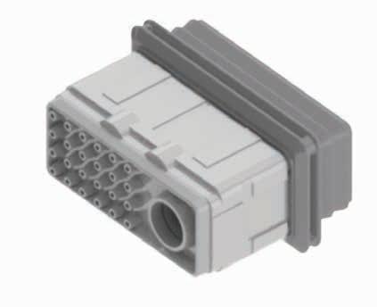
EPXB2 FOR LRU
Largely used in distributed architecture, small Line Replaceable Units in an aircraft need compact, lightweight and cost-effective connectors.
EPXB2 connectors equipped with centering guide will combine high density, low efforts and lightweight features � Discover the whole range of EPXB inserts offering from signal to power or quadrax contacts (available in straight or right angle PC tails and crimp contacts)
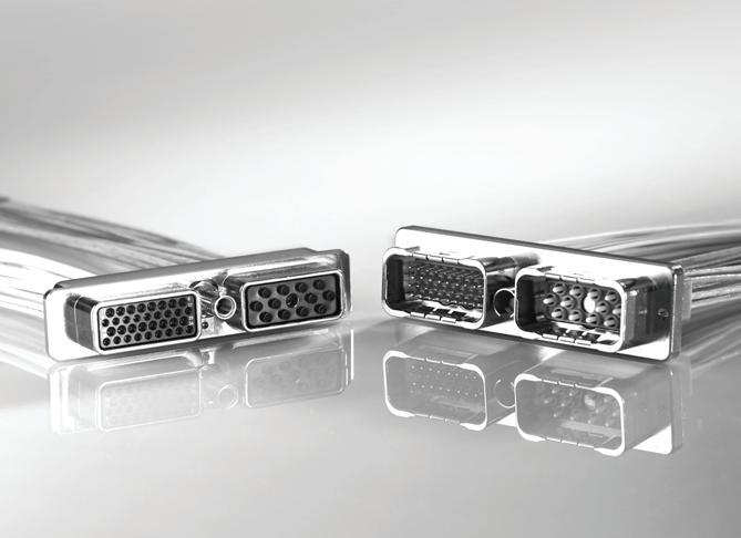
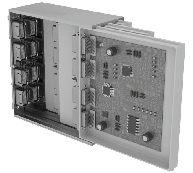
EPX RACK & PANEL FOR LRM
Today, equipment manufacturers look for more costeffective and easy to maintain solutions such as Line Replaceable Module (LRM) As a result, Radiall has developed a new generation of Rack & Panel connectors EPX® Rack & Panel connectors feature a modular, lightweight and high density shell that can be used on standalone PCB architecture�
EPX® Rack & Panel connectors are the perfect solution when equipment needs to combine compactness, weight savings and very high density. They offer:
• A modular range: From size 1 to size 4 using the complete range of EPX® inserts �
• Low mating force contacts from EPX® range that can reach very high density
• A comprehensive range of contacts: Right angle or straight PC tails for signal, coax, quadrax, or power contacts �
EPX SEr IES | 1-5 SIMPLIFICATION IS OUR INNOVATION Visit www.radiall.com for more information Introduction
EPXB2 FOR LRU
EPX RACK & PANEL FOR LRM
EPX® Series
DISCONNECT CONNECTORS
ELECTRICAL CHARACTERISTICS
EMI Shielding Effectiveness EN2591-213
OTHER CHARACTERISTICS
• Shell-to-Shell Conductivity: < 2.5 mΩ
• Operating Voltage: 400 VRMS or 500 VDC at sea level, according to EN2591-205
• Voltage Stability (Ground Block): Maximum variation 4 mV according to SAE AS 81714 (MIL-T-81714)
• Lightning Strike:
- 5 kA - 1,600 V for EPX® connectors in aluminium version
- 3 kA - 1,600 V for EPX® connectors in composite version
MECHANICAL CHARACTERISTICS
MATING/UNMATING
EPXA1/EPXB1/EPXB2 Aluminium
EPXB1/EPXB2 Composite
• EPXB2 mating torque: 1 2N m +/- 0 1
VARIATION & SHOCK
SHELL TYPE MATERIAL
EPXA1 / EPXB1 Aluminium
EPXB1 / EPXB2 Composite
EPXB2 Aluminium
Cycles
Cycles
VIBRATION For 8 hrs on Each of the 3 Axis/Interruption < 1 µs EN2591-403 EIA 364-28 SHOCK 3 Shocks on Each Axis EN2591-402 EIA 364-27
Acceleration 27 8 g (Test Condition 6 Letter G) Shock Amplitude 50 g/Duration 11 ms
Disconnect EPX® with Quadrax ContactsAcceleration 16 �9 g (Test Condition 5 Letter E)
ENVIRONMENTAL CHARACTERISTICS
• Temperature Range: according to EIA364-32 and EN2591-305
- For EPXB2 aluminium, EPXB1 and EPXA1 shells: -65 °C/+175 °C (-85 °F/+347 °F)
- For EPXB2 composite shell: -65 °C/+125 °C (-85 °F/+257 °F)
• Temperature Life: 1,000 hours at maximum temperature
Shock Amplitude 300 g/Duration 3 ms
Shock Amplitude 50 g/Duration 11 ms
• Salt Spray: 96 hours (nickel-plated aluminium and composite) EN2591-307 EIA 364-26 test condition A
• Humidity: 10 days with temperature variation from -10 °C to +65 °C EIA 364-31 Method 4, test condition B
• Altitude Immersion: EN2591-314 EIA 364-03:
- EPXB insert: 3 cycles at 50,000 ft
- EPXB Bulkhead class insert: 3 cycles at 55,000 ft
• Air Leakage for EPXB2 Bulkhead Receptacle: Level from EN3645; test according EN2591-312 method B:
- 4�4 × 10 -3 cm3/s (= 16 × 10-6 m3/h)
1-6 | EPX SEr IES SIMPLIFICATION IS OUR INNOVATION Visit www.radiall.com for more information
FREQUENCY ( MHz) LEAKAGE ATTENUATION (dB) 100 65 200 or 300 63 400 62 500 and 600 60
SHELL
MATERIAL MATING/UNMATING
TYPE
100
100
100
100
EPX® Series
RACK & PANEL CONNECTORS
ELECTRICAL CHARACTERISTICS
EMI Shielding Effectiveness EN2591-213
(MH z)
OTHER CHARACTERISTICS
• Shell-to-Shell Conductivity: < 2.5 mΩ according to EN2591-205
• Lightning Strike: 5 kA - 1,600 V
MECHANICAL CHARACTERISTICS
MATING/UNMATING SHELL TYPE MATERIAL
MATING/UNMATING
EPXB1/EPXB2/EPXB3/EPXB4 Aluminium 500 Cycles
The minimum mating forces are described in the EN4644 standard and depends on the connector size and insert arrangement Consult Radiall for more information
VARIATION & SHOCK
SHELL TYPE MATERIAL
EPXB1/EPXB2/EPXB3/EPXB4 Aluminium
ENVIRONMENTAL CHARACTERISTICS
VIBRATION
For 8 hrs on Each of the 3 Axis/Interruption < 1 µs EN2591-403 EIA 364-28
• Temperature Range: -65 °C/+125 °C (-85 °F/+257 °F)
SHOCK 3 Shocks on Each Axis EN2591-402 EIA 364-27
Acceleration 16 9 g (Test Condition 5 Letter E) Shock Amplitude 50 g/Duration 11 ms
• Temperature Life: 1,000 hours at maximum temperature
• Salt Spray: 96 hours EN2591-307 EIA 364-26 test condition A
• Humidity: 10 days with temperature variation from -10 °C to +65 °C EIA 364-31 Method 4, test condition B
• Altitude Immersion: 3 cycles at 50,000 ft EN2591-314 EIA 364-03
EPX SEr IES | 1-7 SIMPLIFICATION IS OUR INNOVATION Visit www.radiall.com for more information
FREQUENCY
LEAKAGE ATTENUATION (dB) 100 65 200 and 300 63 400 62 500 and 600 60
ELECTRICAL CHARACTERISTICS
Electrical characteristics conform to SAE AS 39029 (MIL-C-39029, type A). Contacts conform to EN3155-076 and EN3155-077.
GROUND BLOCK CONTACT 617221050
DIELECTRIC WITHSTANDING VOLTAGE
EN2591-207 EIA 364-20 with Leakage Current < 1mΩ
INSULATION RESISTANCE
EN2591-206 EIA 364-21
Notes
1. Size 5 contacts are not part of SAE AS 39029 (MIL-C-39029, type A). INSERTS & CONTACT
1-8 | EPX SEr IES SIMPLIFICATION IS OUR INNOVATION Visit www.radiall.com for more information EPX® Series CONTACTS CONTACT SIZE WIRE SIZE MAX CURRENT AMPS 22 AWG22 5 AWG24 3 AWG26 2 20 AWG20 7 5 AWG22 5 AWG24 3 16 AWG16 13 AWG18 10 AWG20 7 5 12 AWG12 23 AWG14 17 AWG16 13 8 AWG8 46 5 AWG8 46 [1] AWG12 23 AWG16 13
CONTACT WITH WIRE SIZE MAX CURRENT AMPS Contact to Contact Contact + AWG20 7 5 Contact to Mounting Surface Contact + AWG20 7 5
LEVEL ENVIRONMENTAL INSERTS VOLTAGE (VRMS) NON-ENVIRONMENTAL INSERT VOLTAGE (VRMS) Sea Level 1,500 1,500 50,000 feet 800 600 70,000 feet 800 300
TEMPERATURE INSULATION RESISTANCE Ambient Temperature > 5,000 mΩ 175 °C (+347 °F) > 200 mΩ
INSERTS & CONTACT
RETENTION CHARACTERISTICS
Retention forces indicated below are valid for terminated contacts (as per EN2591-409 and EIA364-29).
• Insert Retention: 400 N (90 lbs) (EN2591-410 EIA 364-35)
• Maximum Insert Displacement in the Shell Cavity: 0 30 mm (0 012 in )
EPX SEr IES | 1-9 SIMPLIFICATION IS OUR INNOVATION Visit www.radiall.com for more information EPX® Series
CONTACT SIZE RETENTION FORCE MAX DISPLACEMENT Ground Block 88 N (20 lbs) 0 30 mm (0 012 in ) 22 53 4 N (12 lbs) 0 38 mm (0 015 in ) 20 89 N (20 lbs) 0 38 mm (0 015 in ) 16 111 2 N (25 lbs) 0 38 mm (0 015 in ) 12 133 45 N (30 lbs) 0 38 mm (0 015 in ) 8 133 45 N (30 lbs) 0 38 mm (0 015 in ) 5 133 45 N (30 lbs) 0 38 mm (0 015 in )
INSERT SELECTION TABLE
Insert name should be used when ordering EPX® insert
Insert code should be used when ordering EPX® assembly kit
Inserts available in Bulkhead class are identified with the following icon:

1. Only contacts marked with an asterisk (*) are included with EPX® insert kit. All other
fiber optic contacts).
1-10 | EPX SEr IES SIMPLIFICATION IS OUR INNOVATION Visit www.radiall.com for more information
Inserts
contacts must be ordered separately
coax, twinax, quadrax and
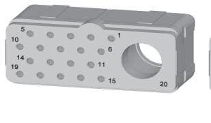
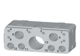
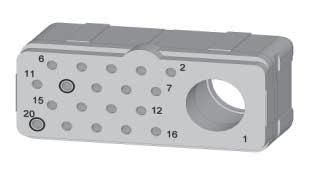
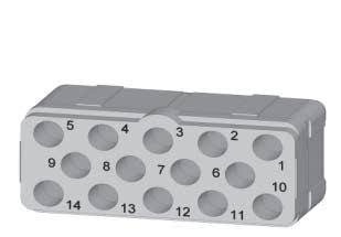
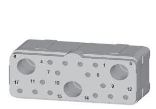
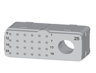
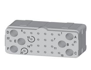
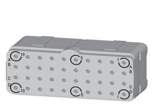
SERIES INSERT NAME INSERT CODE CONTACT SIZE & TYPE TOTAL CONTACTS 22* 20* 15 OR 16* 16 16 12* 8 8 5 5 SIGNAL POWER POWER OR COAX LUXCIS ® FIBER OPTIC POWER IN FIBER OPTIC CAVITY POWER OR COAX POWER QUADRAX OR TWINAX COAX OR TRIAX POWER EPXA 00 0 - - - - - - - - - - 0 1C1 A - - - - - - - - 1 - 1 1P1 B - - - - - - - - - 1 1 04 C - - 2 - - 2 - - - - 4 09 D - 3 6 - - - - - - - 9 14 E - 14 - - - - - - - - 14 14M F 8 3 3 - - - - - - - 14 17 G 12 5 - - - - - - - - 17 20 H 20 - - - - - - - - - 20 0 - - - - - - - - - - 0 A - - - - - - - - 3 - 3 B - - - - - - - - - 3 3 C - - - - - - - 3 - - 3 D - - - - - 6 - - - - 6 E - 8 - - - - - 2 - - 10 F - - - 6 6 - - - - - 12 G - - - 12 - - - - - - 12 H - 6 4 - - 2 - - 1 - 13 J - 6 4 - 2 - - - 1 13 K - - 14 - - - - - - - 14 L - 14 - - - 3 - - - - 17 M - 19 - - - - - - 1 - 20 20P1 N - 19 - - - - - - - 1 20 22 P - 16 6 - - - - - - - 22 Q - 16 6 - - - - - - - 22 R 24 - - - - - 1 - - - 25 S 24 - - - - - - 1 - - 25 T 22 - 6 - - - - - - - 28 U - 30 - - - - - - - - 30 W 18 16 - - - - - - - - 34 X 40 - - - - - - - - - 40 Y 48 - - - - - - - - - 48
(i.e.
Inserts
HOW TO ORDER EPX® INSERTS
Only crimp contacts can be delivered with insert
SERIES PREFIX
INSERT SIZE [1]
A: Insert for EPXA
B: Insert for EPXB1, EPXB2, EPXB3 or EPXB4
CLASS [2]
E: Environmental
N: Non-environmental (no rear grommet, no interfacial seal)
EPX
H: Non-environmental with a rear grommet, available for pin insert only (recommended for crimp contacts)
T: Non-environmental with an interfacial seal, available for pin insert only (recommended for PC tail contacts)
B: Bulkhead insert with interfacial seal and a Bulkhead rear grommet, available for pin insert only
INSERT NAME
Refer to table on page 1-10 for insert arrangements
INSERT TYPE
P: Pin
S: Socket
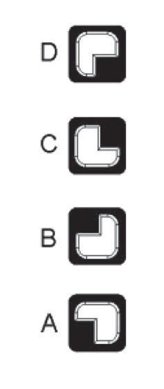
INSERT KEYING [3]
A: Keying A
B: Keying B
CONTACT
Without Code: Insert delivered without contacts
S: Signal and power contacts are delivered with inserts but are uninstalled (refer to page 1-10) Inserts 00, 1C1, 1P1, C3, P3, 3Q3, 12F6, F12C and 3T3 are not available in S contact version
ENVIRONMENTAL INSERT
BULKHEAD INSERT
INSERT KEYING DETAIL
Notes
1. Inserts are designed for rear-release and rear-removable contacts.
2. Pin and socket inserts can be installed in either plug or receptacle shell. F6, F12C and 12F6 are only available in E class. Insert 00 is only available in N class.
3. For EPXA1, EPXB1, EPXB3 and EPXB4 shells, use only insert keyed A. For EPXB2 shells, use one insert keyed A and one insert keyed B.
EPX SEr IES | 1-11 SIMPLIFICATION IS OUR INNOVATION Visit www.radiall.com for more information
Keying A
Keying B
Rear Grommet
Bulkhead Rear Grommet
Socket Insert Rear Grommet
Interfacial Seal
Pin Insert
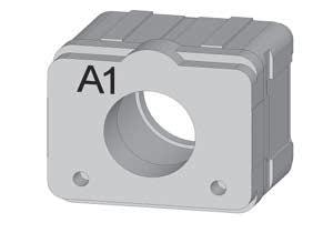
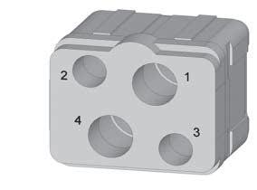
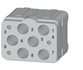
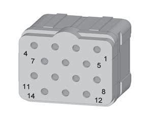
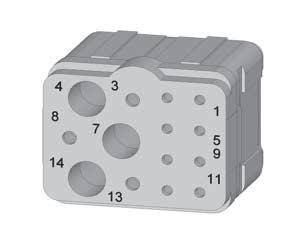
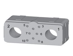
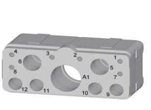
1-12 | EPX SEr IES SIMPLIFICATION IS OUR INNOVATION Visit www.radiall.com for more information Inserts Notes 1. P/N for blank insert is EPXAN00. EPXA INSERT ARRANGEMENTS Insert Name 00 Insert Code 0 Blank Insert [1] Insert Name 1C1 Insert Code A 1 × size 5 Coax Contacts Insert Name 1P1 Insert Code B 1 × Size 5 Power Contacts Insert Name 04 Insert Code C 2 × Size 15 or 16 Contacts 2 × Size 12 Contacts Insert Name 09 Insert Code D 3 × Size 20 Contacts 6 × Size 15 or 16 Contacts Insert Name 14 Insert Code E 14 × Size 20 Contacts Insert Name 14M Insert Code F 8 × Size 22 Contacts 3 × Size 20 Contacts 3 × Size 15 or 16 Contacts Insert Name 17 Insert Code G 12 × Size 22 Contacts 5 × Size 20 Contacts Insert Name 20 Insert Code H 20 × Size 22 Contacts WEIGHTS Average weight per class and type for EPXA inserts without contacts. INSERT CLASS INSERT TYPE PIN SOCKET E 4 10 g (0 14 oz) 5 30 g (0 19 oz) N 2 60 g (0 09 oz) 4 00 g (0 14 oz) H 3 �90 g (0�14 oz) N/A T 2 80 g (0 10 oz) N/A EPX® INSERT ARRANGEMENTS
EPX® INSERT ARRANGEMENTS
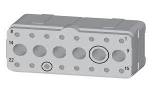
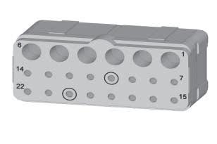
EPXB INSERT ARRANGEMENTS Full size inserts arrangements are compliant with EN4644. Insert Name 00
Insert Name 06
Code D
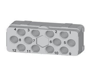
Code E
× Size 12 Medium Power Contacts Insert Name 10Q2
Insert Name 13C1
Code H
× Size 20 Contacts
× Size 15 or 16 Contacts
Insert Name 20C1
Code M
× Size 20 Contacts
Code F
× Size 20 Contacts
Code J
Code N
× Size 5 Coax Contacts Insert Name 20P1
Notes 1. P/N for blank insert is EPXBN00.
Code G
Code P
Code Q
× Size 20 Contacts
× Size 16 Contacts
EPX SEr IES | 1-13 SIMPLIFICATION IS OUR INNOVATION Visit www.radiall.com for more information Inserts
Insert
3
Insert
3
Insert
Insert
3
Insert Code 0 Blank Insert Insert Name C3
Code A
× size 5 Coax Contacts Insert Name P3
Code B
× Size 5 Power Contacts
Name 3Q3
Code C
× Size 8 Quadrax Contacts
Insert
6
Insert
8
2
Insert
6
6
Insert
12
× Size 8 Quadrax Contacts Insert Name 12F6
× Size 16 Optical LuxCis® Termini
× Size 16 Special Electrical Contacts Insert Name F12C
× Size 16 Optical LuxCis® Termini
6
4
2
1
Insert
6
4
2
1
Insert
14
Insert
14
3
Insert
× Size 12 Contacts
× Size 5 Coax Contacts Insert Name 13P1
× Size 20 Contacts
× Size 15 or 16 Contacts
× Size 12 Contacts
× Size 5 Coax Contacts Insert Name 14
Code K
× Size 15 or 16 Contacts Insert Name 17
Code L
× Size 20 Contacts
× Size 12 Contacts
19
1
Insert
19
1
Insert
16
6
Insert
16
6
Insert
× Size 20 Contacts
× Size 5 Coax Contacts Insert Name 22
× Size 20 Contacts
× Size 15 or 16 Contacts Insert Name 22V
Inserts
EPX® INSERT ARRANGEMENTS
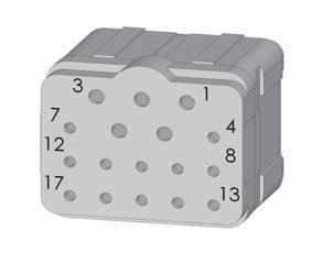
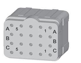
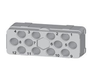
EPXB INSERT ARRANGEMENTS
Full size inserts arrangements are compliant with EN4644.
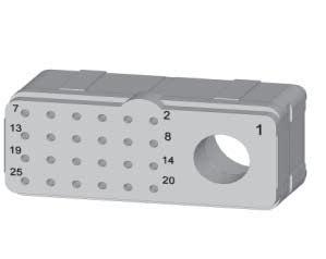
Insert Name 25P1
Insert Code R 24 × Size 22 Contacts 1 × Size 8 Power Contacts
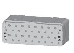
Insert Name 34
Insert Code W 18 × Size 22 Contacts 16 × Size 20 Contacts
WEIGHTS
Insert Name 25Q1
Insert Code S 24 × Size 22 Contacts 1 × Size 8 Quadrax Contacts
Insert Name 40 Insert Code X 40 × Size 22 Contacts
Average weight per class and type for EPXB inserts without contacts.
Insert Name 28 Insert Code T 22 × Size 22 Contacts 6 × Size 15 or 16 Contacts Insert Name 30
Code U 30 × Size 20 Contacts
Insert Name 48 Insert Code Y 48 × Size 22 Contacts
1-14 | EPX SEr IES SIMPLIFICATION IS OUR INNOVATION Visit www.radiall.com for more information
Insert
INSERT
INSERT TYPE PIN SOCKET E 7 90 g (0 28 oz) 10 00 g (0 35 oz) N 5 20 g (0 18 oz) 7 60 g (0 27 oz) H 7 70 g (0 27 oz) N/A T 5 50 g (0 19 oz) N/A B 8 50 g (0 30 oz) N/A
CLASS
SIGNAL & POWER CRIMP CONTACTS
EPX® series offers a wide range of contacts compliant with EN3155 and SAE AS 39029. The available contacts cover aerospace applications for terminating to both cables and printed circuit boards - Signal and power contacts - Ethernet links with Quadrax contacts - High frequency with coax, twinax and triax contacts - Optical links with LuxCis® contacts
Notes
1. Electrical contacts for optical inserts are always pin contacts (hermaphrodite).
2. In order to make these contacts environmental, it is necessary to add a sealing boot. Please contact us for additional information.
3. These power contacts can be used in power inserts only (25P1).
4. These power contacts can be used in power inserts only (P3, 13P1 and 20P1).
EPX SEr IES | 1-15 SIMPLIFICATION IS OUR INNOVATION Visit www.radiall.com for more information Contacts CONTACT SELECTION TABLE CONTACT SIZE WIRE SIZE TYPE ENVIRONMENTAL PART NUMBER NONENVIRONMENTAL PART NUMBER CRIMPING TOOL POSITIONER SELECTION INS/EXT TOOL MATERIAL OF TOOL 22 22 Pin 617200 282281 M22520/2-01 282970 M22520/2-23 4 282522 (M81969/14-01) Plastic 24 3 26 Socket 617300 20 20 Pin 617221 282281 M22520/2-01 282971 M22520/2-08 7 282522001 (M81969/3901) Plastic 22 6 24 Socket 617320 5 16 16 Pin 617240 282291 M22520/1-01 282972 M22520/1-02 6 282515 (M81969/14-03) Plastic 18 Socket 617340 5 20 4 For Ground Block 20 Pin 617221050 282281 M225520/2-01 282581015 M22520/2-11 7 282886 M81969/1-02 Metal Socket N/A For Optical/ Electrical Cavity 16 Pin 617235003 [1] 282291 M22520/1-01 282581013 6 282515 (M81969/14-03) Plastic 18 5 20 4 12 12 Pin 617250 282291 M22520/1-01 282972 M22520/1-02 8 282549004 (M81969/1404) Plastic 14 Socket 617350 7 16 6 8 8 Pin
for AWG8 617291002
R282600000
Die set R282650000 M22520/23-02 282588 N/A 282549001 Metal Socket 617391008 for AWG8 617391002 [2&3] 10 5 8 Pin
10 617280
R282600000
Die set R282650000 M22520/23-02 282557020 N/A 282946
Metal Socket
617390
282557021 10 12 Pin 617260002 617260001 [2&4] 282613 282586003 6 16 Socket 617370005 617370001 [2&4] 282586005 4
617291007
[2&3]
M22520/ 23-01 +
617280003 for Size 8, 617280004 for Size
[2&4]
M22520/ 23-01 +
(M81969/2801)
617390003 for Size 8, 617390004 for Size 10
[2&4]
OVERSIZED & REDUCED CRIMP BARREL CONTACTS
1-16 | EPX SEr IES SIMPLIFICATION IS OUR INNOVATION Visit www.radiall.com for more information Contacts Notes 1. Electrical contacts for optical inserts are always pin
contacts (hermaphrodite).
CONTACT SIZE WIRE SIZE TYPE PART NUMBER FULL PLATED CRIMPING TOOL POSITIONER SELECTION INS/EXT TOOL MATERIAL OF TOOL 22 Reduced Crimp Barrel 28 Pin 617201 282281 M22520/2-01 282970 M22520/2-23 5 282522 (M81969/14-01) Plastic 30 Socket 617301 4 Oversize Crimp Barrel 20 Pin 617200200 282281 M22520/2-01 282970 M22520/2-23 5 22 Socket 617300200 4 24 3 20 Reduced Crimp Barrel 22 Pin 617224001 282281 M22520/2-01 282971 M22520/2-08 4 282522001 (M81969/39-01) Plastic 24 Socket 617324001 3 26 3 Oversize Crimp Barrel 18 Pin 617221200 282281 M22520/2-01 282971 M22520/2-08 5 20 Socket 617320200 5 22 4 16 Reduced
Barrel 20 Pin 617241 282291 M22520/1-01 282972 M22520/1-02 5 282515 (M81969/14-03) Plastic 22 Socket 617341 5 24 4 Reduced Crimp Barrel for Optical Electrical Cavity 20 Pin 617235002 [1] 282291 M22520/1-01 282581013 5 22 5 24 4 Oversize Crimp Barrel 14 Pin 617240200 282291 M22520/1-01 282972 M22520/1-02 6 16 Socket 617340200 5 18 5
Crimp
Contacts
COAXIAL CRIMP CONTACTS
RG188 FILECAF1709/6 F1709/8 RG174-RG179-RG316 ASNE0639XY 75 Ohms
RG178
15-16
GORE/AXON P812817 FILECA F1703-134 FILOTEX SP132868
RG178 DT
12 UT 085-RG405
5 RG58-RG141
RG142 - RG400
RG174-RG316-RG188RG178DS NEXAN 10036442 75 Ohms
617003001 617003
RG178-RG196 Pin 617104001 617104 Socket 617004001 617004
RG180 PAN6422XZ ANSE063WGH 96 Ohms
(M81969/14-03)
(M81969/14-04)
(M81969/28-01)
EPX SEr IES | 1-17 SIMPLIFICATION IS OUR INNOVATION Visit www.radiall.com for more information
TYPE TYPE ENVIRONMENTAL PART NUMBER NON-ENVIRONMENTAL PART NUMBER INS/EXT TOOL MATERIAL OF TOOL
CONTACT SIZE CABLE
Pin 617130 282512
Metal Socket 617030
Pin
617131 Socket 617031
Pin
617132 Socket 617032
Pin
Pin
617133 Socket 617033 UT 047
617135 Socket 617035
Pin 617160 282549004
Plastic Socket
617060
Pin
617101 282946
Metal Socket
617001
617101001
617001001
Pin 617102001 617102 Socket 617002001 617002
Pin
617103001 617103 Socket
Pin
617105001 617105 Socket 617005001 617005
Contacts
TWINAX & TRIAX CRIMP CONTACTS
CONTACT SIZE
12 Triax
8 Triax
8 Twinax
5 Triax
ECS0700 Pin 617190010
282549004 (M81969/14-04) Plastic Socket 617090010
M17/176-00002 Pin 617190012 Socket 617090012
TENSOLITE 24463/9PO25X-2 100 Ohms Pin 617165021
WHITMOR W2675-1575
617165020
Socket 617065021 617065020
617165 617165001 Socket 617065 617065001
282549001 Metal
ABS0386WF24 & TYCO 1726A1424A Pin 617165011 620165010 282549001 Metal Socket 617065011 620065010
PAN6421ZA002 77 Ohms
M17/176-00002 EN3375-003 Raychem 106113 77 Ohms Pin 617150001 617150
282946 (M81969/28-01) Metal Socket 617050001 617050
TENSOLITE 24473/03159X 124 Ohms Pin 617152001 617152
Socket 617052001 617052
1-18 | EPX SEr IES SIMPLIFICATION IS OUR INNOVATION Visit www.radiall.com for more information
CABLE TYPE TYPE ENVIRONMENTAL PART NUMBER NON-ENVIRONMENTAL PART NUMBER INS/EXT TOOL MATERIAL OF TOOL
Pin
Contacts
QUADRAX & BMA CRIMP CONTACTS
QUADRAX CONTACTS
The Quadrax contact offer is compliant with Arinc 600 and EN3155-072 and EN3155-073 standards.
ENVIRONMENTAL QUADRAX
CONTACT
8
Ethernet Cable ABS0972 and ABS1503
TENSOLITE NF24Q100
TENSOLITE NF26Q100/JSF Y18
TENSOLITE NF22Q100
NON-ENVIRONMENTAL QUADRAX
CONTACT
Ethernet Cable ABS0972 and ABS1503
TENSOLITE NF24Q100
TENSOLITE NF26Q100/JSF Y18
TENSOLITE NF22Q100
BMA CONTACTS
CONTACT SIZE
Pin
Socket 617075011
Pin
617175051
Socket 617075051
Pin
617175011 282549001
617175053
Socket 617075053
Pin
617175041
Socket 617075041
Pin 617175012
Socket 620075010
Pin 617175052
Socket 620075050
Pin 617175054
Socket 620075021
Pin 617175040
Socket 620075040
Extraction tool 282549001 is used for size 8 BMA contacts � Environmental BMA contacts are all provided with sealing boots �
617939003
617939005
617939003
282549001
Notes 1. BMA contacts which can accommodate SHF cables require a termination by Radiall.
EPX SEr IES | 1-19 SIMPLIFICATION IS OUR INNOVATION Visit www.radiall.com for more information
EXTRACTION TOOL IN METAL
SIZE CABLE TYPE TYPE NONENVIROMNMENTAL PART NUMBER COMPATIBLE SEALING BOOT PART NUMBER
8
TYPE CONNECTOR TYPE ENVIRONMENTAL PART NUMBER NON-ENVIRONMENTAL PART NUMBER FREQUENCY RANGE MAX VSWR INSERTION LOSS 8 SHF5
Pin 617171011 617171010 DC-18 GHz 1 35 0 13 dB at Max Frequency (18 GHz) RG142 Pin 617171021 617171020 DC-12 4 GHz 1 35 0�11 dB at Max Frequency (12 4 GHz) SHF2 4M
085/
SS405/ Times Tflex405 Pin 617171031 617171030 DC-18 GHz 1 35 0 13 dB at Max Frequency (18 GHz) SHF5
Socket 617071011 617071010 DC-18 GHz 1 35 0 13 dB at Max Frequency (18 GHz) RG142 Socket 617071021 617071020 DC-12 4 GHz 1 35 0 11 dB at Max Frequency (12 4 GHz) SHF3
Socket 617071041 617071040 DC-18 GHz 1� 35 0�13 dB at Max Frequency (18 GHz)
CABLE
- SHF5M [1]
[1] /UT
Harbour
- SHF5M [1]
[1]
TYPE TYPE ENVIRONMENTAL PART NUMBER EXTRACTION TOOL IN METAL
SIZE CABLE
Contacts
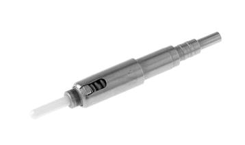
LUXCIS® FIBER OPTIC CONTACTS
The LuxCis® product range is a proven, flexible fiber optic interconnect solution offering high-speed communication in aerospace and other harsh environments �
OPTICAL PERFORMANCE
Insertion Loss (IL) Mean (IEC 61300-3-4 Method B)
Return Loss (RL) (IEC 61300-3-6)
MECHANICAL & ENVIRONMENTAL CHARACTERISTICS
SAE AS 13441 Method 2002 1
Cycles Cable Retention 1 8 mm Diameter 900 µm Diameter SAE AS 13441 Method 2009 1 68 N 7 N Humidity TIA/EIA 455-5
LUXCIS ® CONTACT PA r T NUMBEr ING SYSTEM
LUXCIS ® SERIES
FERRULE TYPE
00: PC ferrule for single-mode fiber
03: PC ferrule for 50/125 or 62.5/125 μm multi-mode fiber
04: PC ferrule for 100/40 um multi-mode fiber
05: PC ferrule for 200/230 um multi-mode fiber
50: APC ferrule for single-mode fiber
CABLE TYPE AND DIAMETER
118: 900 μm cable
318: 1 2 mm cable with strengthening members, tight structure
419: 1�6 to 2 � 2 mm cable, loose structure
519: 1�6 to 2 � 2 mm cable, tight structure
[1]
Cycles/24 h 90% RH -25 °C/+65 °C
F7250
The sealing plug F718 211 200 is specifically designed to fill the unused LuxCis® Arinc 801 cavities
Notes
1. Mating cycles are dependant on the connector series. Radiall can support you with your cable and harness assemblies. Please contact your sales representative.
1-20 | EPX SEr IES SIMPLIFICATION IS OUR INNOVATION Visit www.radiall.com for more information
MULTIMODE
850/1300
SINGLEMODE
1310/1550
(PC)
Nm
(UPC)
Nm
0
dB 0 15 dB
20 dB > 50 dB
1
>
STANDARD PERFORMANCE Thermal Cycling SAE AS
1003 �1 -55 °C/+125 °C (Cable Dependant) Temperature Endurance TIA/EIA 455-4 1,000 h at 125 °C (Cable
Vibration TIA/EIA
27 g Shock TIA/EIA
50 g, 11 ms Durability TIA/EIA
500
13441 Method
Dependant)
455-11
455-14
364-09
Cycles
Maintenance
10
10
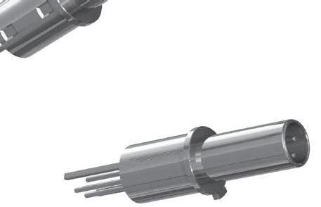
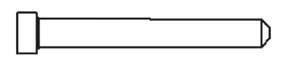
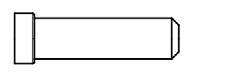
SIGNAL PC TAIL CONTACTS
Selection Table for Straight PC Tail Contacts
Contact termination designations are a combination of 2 letters:
- The first letter characterizes the contact plating R = Pure-tin (RoHS); Z = Tin lead; Y = Gold
- The second letter characterizes the length of the PC tail: A to D The exact lengths can be found on the assembly kit sections
EPX SEr IES | 1-21 SIMPLIFICATION IS OUR INNOVATION Visit www.radiall.com for more information
CONTACT TERMINATION CONTACT TYPE SIZE 22 SIZE 20 SIZE 16 SIZE 12 SIZE 8 SIZE 5 RA Pin 617205510 617222514 617242510 617259505 617291501 617289506 Socket 617305500 617322505 617342510 617359505 617391501 617389506 YA Pin 617205010 617222014 617242010 617259005 617291001 617289006 Socket 617305 617322005 617342010 617359005 617391001 617389006 ZA Pin 617205710 617222714 617242710 617259705 617291701 617289706 Socket 617305700 617322705 617342710 617359705 617391701 617389706 RB Pin 617205501 617222512 617242508 617259506 617291503 617289504 Socket 617305501 617322506 617342511 617359506 617391503 617389504 YB Pin 617205001 617222012 617242008 617259006 617291003 617289004 Socket 617305001 617322006 617342011 617359006 617391003 617389004 ZB Pin 617205701 617222712 617242708 617259706 617291703 617289704 Socket 617305701 617322706 617342711 617359706 617391703 617389704 RC Pin 617205515 617222513 617242517 617259503 617291504 617289503 Socket 617305508 617322507 617342513 617359503 617391504 617389503 YC Pin 617205015 617222013 617242017 617259003 617291004 617289003 Socket 617305008 617322007 617342013 617359003 617391004 617389003 ZC Pin 617205715 617222713 617242717 617259703 617291704 617289703 Socket 617305708 617322707 617342713 617359703 617391704 617389703 RD Pin 617205509 617222510 617242509 617259507 617291505 617289507 Socket 617305502 617322509 617342515 617359507 617391505 617389507 YD Pin 617205009 617222010 617242009 617259007 617291005 617289007 Socket 617305002 617322009 617342015 617359007 617391005 617389007 ZD Pin 617205709 617222710 617242709 617259707 617291705 617289707 Socket 617305702 617322709 617342715 617359707 617391705 617389707 Ins/Ext Tool 282522 M81969/14-01 282522001 M81969/39-01 282515 M81969/14-03 282549004 M81969/14-04 282549001 M81969/28-03 282946 M81969/28-01
Contacts
Contacts
QUADRAX SIZE 8 PC TAIL CONTACTS
Selection Table for Straight PC Tail Contacts
Contact termination designations are a combination of 2 letters:
- The first letter characterizes the contact plating R = Pure-tin (RoHS); Z = Tin lead; Y = Gold
- The second letter characterizes the length: A to D� The exact dimensions of the lengths can be found on the assembly kit sections
CONTACT TERMINATION
RA
YA
ZA
RB
YB
ZB
RC
YC
ZC
RD
YD
ZD
CONTACT
Pin
Socket
Pin
617177512
617077512
617177012
Socket 617077012
Pin 617177712
Socket 617077712
Pin
Socket
617177501
617077502
Pin 617177001
Socket 617077002
Pin 617177701
Socket 617077702
Pin 617177508
Socket 617077508
Pin
617177008
Socket 617077008
Pin 617177708
Socket 617077708
Pin 617177513
Socket 617077513
Pin 617177013
Socket 617077013
Pin
617177713
Socket 617077713
Ext Tool 282549001
1-22 | EPX SEr IES SIMPLIFICATION IS OUR INNOVATION Visit www.radiall.com for more information
TYPE PART NUMBERS
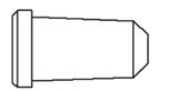
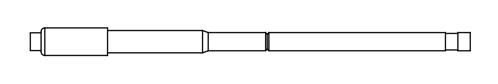
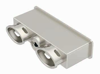
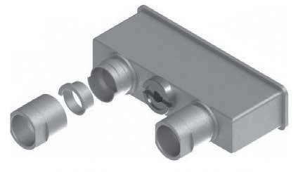
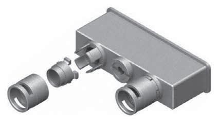
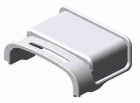
FILLER PLUGS
Filler plugs are dedicated to non-environmental insert cavities. The arrows show the direction which you have to insert the plug.

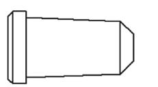
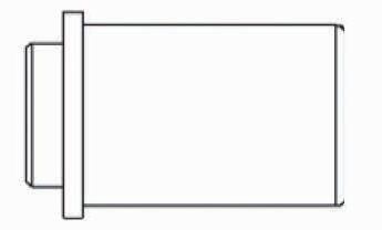
SEALING PLUGS
Sealing plugs are dedicated to environmental insert cavities.
EPX SEr IES | 1-23 SIMPLIFICATION IS OUR INNOVATION Visit www.radiall.com for more information Contacts SIZE CONTACT CAVITY VERSION INS/EXT COLOR PART NUMBER DRAWING 22 For Pin & Socket Rear/Rear Black 620920 20 White 610941 16 For Electrical Cavity Blue 620922 16 For Optical Cavity Green F718211200 12 Yellow 620923 8 Pin Nickel 619953 Socket 619950 5 Pin White 617930 Socket 617931
SIZE CONTACT CAVITY VERSION INS/EXT COLOR PART NUMBER DRAWING 22 For Pin & Socket Rear/ Rear Black 616910 20 Red 616911 16 For Electrical Cavity Green 616912 16 For Optical Cavity F718211200 12 Orange 616913 8 Red 618915 5 616914013
Disconnect Application
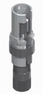
EPXA1 PRODUCT OVERVIEW
Detailed view of receptacle and plug with accessories for the EPXA1 connector:
1-24 | EPX SEr IES SIMPLIFICATION IS OUR INNOVATION Visit www.radiall.com for more information
Insert
Receptacle Shell
Socket Contact
Ground Block
45° Strain Relief
Captive Mounted Screws
Polarization Hardware
Quarter-Turn Locking Device
Straight Strain Relief
Plug Shell
Pin Contact
Disconnect Application
EPXB1 PRODUCT OVERVIEW
Detailed view of receptacle and plug with accessories for the EPXB1 connector:
Receptacle Shell
EPX SEr IES | 1-25 SIMPLIFICATION IS OUR INNOVATION Visit www.radiall.com for more information
Socket Contact
Plug Shell
Insert Quarter-Turn Locking Device
Polarization Hardware
Pin Contact
EMI Backshell
Ground Block
Straight Strain Relief
Disconnect Application
HOW TO ORDER EPXA1 &
EPXB1 SHELL
SERIES PREFIX
SHELL SIZE
A1: Single small cavity shell
B1: Single large cavity shell
SHELL STYLE
P: Plug
R: Receptacle
W: Plug with ground block
Z: Receptacle with ground block
SHELL MOUNTING OPTION [1]
B: Plug without mounting holes
M: Receptacle with two mounting holes, 6-32 UNC for rear panel [2]
LOCKING DEVICE
0: Quarter-turn fastener
POLARIZATION CODE [3]
4: Shell delivered with polarizing hardware unassembled
5: Shell delivered with no polarizing hardware
SHELL CLASS
M: Nickel-plated composite for EPXB1
K: Nickel-plated aluminium for EPXB1 (mateable with version M composite shell)
N: Nickel-plated aluminium for EPXA1
GROUND BLOCK
Radiall provides a unique patented feature by integrating a ground block directly on the shell This option permits very short ground terminations
Notes
M39029/1-101 Contacts Radiall P/N 617221050 Insulator
Shell
Intermediate Plate for Grounding
1. Recommended locking torque: 1.6 Nm (14.16 in.-lb) for metallic shell and 1.1 Nm (9.73 in.-lb) max for composite shell.
2. Self-locking mounting holes are designed for rear panel mounting.
3. Please see page 1-28 on how to use the polarization device.
1-26 | EPX SEr IES SIMPLIFICATION IS OUR INNOVATION Visit www.radiall.com for more information
EPX
Connector
Disconnect Application
HOW TO ORDER EPXA & EPXB1 ASSEMBLY KIT
Assembly kit is delivered fully assembled including shell with insert mounted, with or without contacts, according to the selection.
Tips to help you in your selection:
• You are free to use either pin or socket inserts in EPXA and EPXB1 plug or receptacles
• Crimp contacts can be delivered with a kit; check which contacts would be included on page 1-10
• If PC tail are selected, then all cavities including signal, power and quadrax are populated Size 5 coax cavities are not populated
• If PC tail contacts are needed, remember that they are available as pin straight PC tail contacts in receptacles only
SHELL SELECTION PA r T
SERIES PREFIX
SHELL SIZE
A1: Single small cavity shell
B1: Single large cavity shell
SHELL STYLE
P: Plug
R: Receptacle
W: Plug with ground block
Z: Receptacle with ground block
POLARIZATION CODE
4: Shell delivered with polarizing hardware unassembled
5: Shell delivered with no polarizing hardware
SHELL CLASS
M: Nickel-plated composite for EPXB1
K: Nickel-plated aluminium for EPXB1 (mateable with version M composite shell)
N: Nickel-plated aluminium for EPXA
INSEr T SELECTION PA r T
INSERT CLASS
E: Environmental
N: Non-environmental (no rear grommet, no interfacial seal)
H: Non-environmental insert with a rear grommet, available for pin insert only (recommended for crimp contact)
T: Non-environmental insert with an interfacial seal, available for pin insert only (recommended for PC tail contact)
INSERT CODE
Refer to page 1-10 to select insert code
CONTACTS TERMINATION
XS: Socket insert without contacts [1]
XP: Pin insert without contacts [1]
SS: Socket insert with crimp contacts [1]
SP: Pin insert with crimp contacts [1]
YA: Gold PC tail contacts length A [2]
ZA: Tin-lead PC tail contacts length A [2]
RA: Pure tin (RoHS) PC tail contacts length A [2]
Notes
1. These contacts are delivered uninstalled
2. Refer to page 1-29 to select PC tail contacts for receptacle
EPX SEr IES | 1-27 SIMPLIFICATION IS OUR INNOVATION Visit www.radiall.com for more information
EPX
Disconnect Application
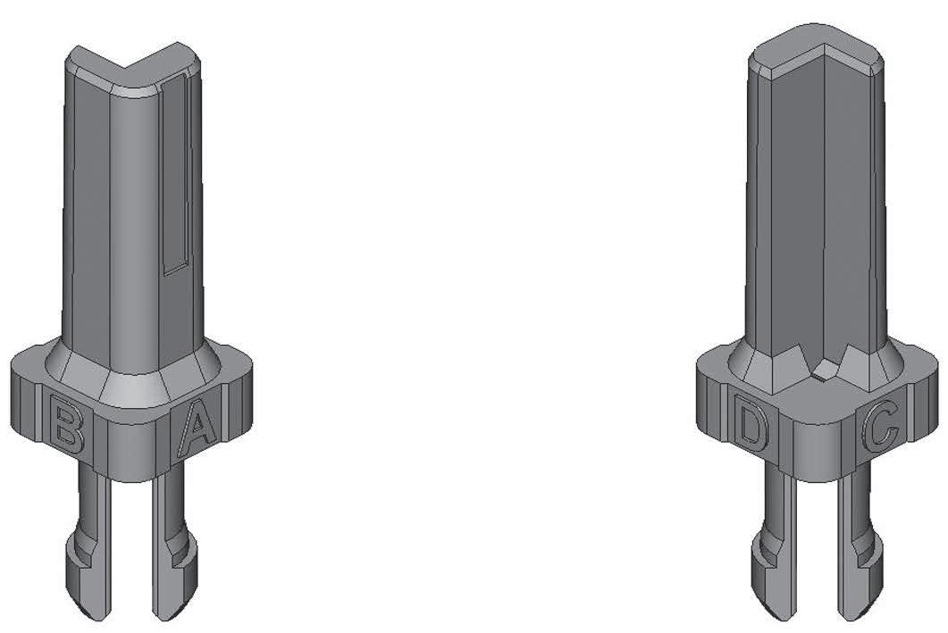
POLARIZATION CODE FOR EPXA1 & B1
Caution: Read the polarization code from left to right, the same way the part number marking can be read on the connector.
PLUG
Coding Device
There are 16 possible codings:
RECEPTACLE
1-28 | EPX SEr IES SIMPLIFICATION IS OUR INNOVATION Visit www.radiall.com for more information
EPXA1
EPXB1
View A and B View C and D
View A and D View C and B
KEY POSITION 1 A A A A B B B B C C C C D D D D KEY POSITION 2 A B C D A B C D A B C D A B C D 1 2 1 2
Disconnect Application
CONTACT TERMINATION FOR EPXB1
E Aluminium and composite shell versions �
STRAIGHT PC TAIL CONTACT TERMINATION MIN LENGTH E MM (INCH)
LENGTH H MM (INCH)
16 � 20 (0 �637) [1] -
19 40 (0 763) [1] - YB
21 25 (0 836) [1] - YC
25 20 (0 992) 5 40 (0 212) YD
Notes
1. These PC tail lengths are not compatible with EPXBE and EPXBH inserts.
EPX SEr IES | 1-29 SIMPLIFICATION IS OUR INNOVATION Visit www.radiall.com for more information
H
MIN
GOLD TIN-LEAD
TIN (ROHS)
PURE
YA ZA RA
ZB RB
ZC RC
ZD RD
Disconnect Application
EPXA1 SHELL DIMENSIONS
Receptacle Plug WITHOUT GROUND BLOCK WITHOUT GROUND BLOCK
Receptacle Plug
SINGLE PANEL CUT-OUT [2]
EPXA1 SHELL WEIGHTS
Weights include the shell with polarization hardware
MULTIPLE PANEL CUT-OUT [2]
Notes
1. Maximum dimension for insert with grommets. For insert without grommet maximum dimensions will be for receptacle 25.55 mm (1.006 in.) and for the plug 23.52 mm (0.926 in.).
2. Rear mounting side view with key post oriented to the upper side.
1-30 | EPX SEr IES SIMPLIFICATION IS OUR INNOVATION Visit www.radiall.com for more information
EPXA1 SHELL STYLE WEIGHT CLASS N P 27 0 g (0 95 oz) R 33 0 g (1 16 oz) W 35 �0 g (1� 23 oz) Z 41 0 g (1 45 oz)
Disconnect Application
EPXB1 SHELL DIMENSIONS
WITHOUT GROUND BLOCK WITHOUT GROUND BLOCK
Receptacle Plug
SINGLE PANEL CUT-OUT [2]
EPXB1 SHELL WEIGHTS
Weights include the shell with polarization hardware
Receptacle Plug
MULTIPLE PANEL CUT-OUT [2]
Notes
1. Maximum dimension for insert with grommet. For insert without grommet: Insert is flush to the shell. Maximum dimension for the receptacle is 25.55 mm (1.006 in.) and for the plug is 23.52 mm (0.926 in.). For insert with optical contacts: the maximum dimension for the receptacle is 38.70 mm (1.524 in.) and the plug is 36.00 mm (1.418 in.).
2. Rear mounting side view with polarization hardware oriented to the upper side.
EPX SEr IES | 1-31 SIMPLIFICATION IS OUR INNOVATION Visit www.radiall.com for more information
2,220 56,39 0,965 24,50
EPXB1 SHELL STYLE WEIGHT CLASS K P 27 0 g (0 95 oz) R 33 0 g (1 16 oz) W 37 0 g (1 31 oz) Z 43 0 g (1 52 oz) CLASS M P 25 0 g (0 88 oz) R 33 0 g (1 16 oz) W 35 0 g (1 23 oz) Z 43 0 g (1 52 oz)
Disconnect Application
EPXA1 & EPXB1 SPARE PARTS
SPARE PARTS & DUST CAPS

617980032
617980033
Polarization Kit for Plug Connector
Polarization Kit for Receptacle Connector
Post
617954006
Key
617954008 Dust Cap for Plug Shell (Pink Color)
617954007 617954009 Dust Cap for Receptacle Shell (Pink Color)
617954044 617954034 ESD Dust Cap for Plug Shell (Black Color)
617954045
617929033
617954028 ESD Dust Cap for Receptacle Shell (Black Color)
Sealing Inserts for Fly Away Applications: Mateable with Pin Insert
617929023
617929032
Sealing Inserts for Fly Away Applications: Mateable with Socket Insert
1-32 | EPX SEr IES SIMPLIFICATION IS OUR INNOVATION Visit www.radiall.com for more information
PART NUMBER
EPXA EPXB1
DESCRIPTION
-
-
-
Polarization
-
Polarization
617980030
617980031
-
-
-
-
617929022
Disconnect Application
EPXA1 & EPXB1 ACCESSORIES
STRAIN RELIEFS & EMI BACKSHELLS
617921030 617921029
DESCRIPTION
Straight Strain Relief (Composite)
617921032 617921031 45° Strain Relief (Composite)
617924016
617928002
Straight EMI Backshell (Nickel-Plated Aluminium)
Notes For mounting instructions, please contact Radiall.
617921044
Straight EMI Backshell (Nickel-Plated Composite)
Fiber Optic Backshell (Composite)
EPX SEr IES | 1-33 SIMPLIFICATION IS OUR INNOVATION Visit www.radiall.com for more information
PART NUMBER
EPXA1
EPXB1
-
-
-
Disconnect Application
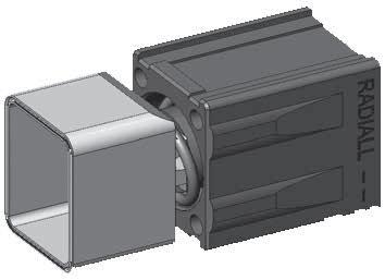
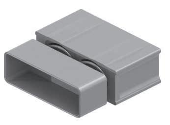
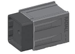
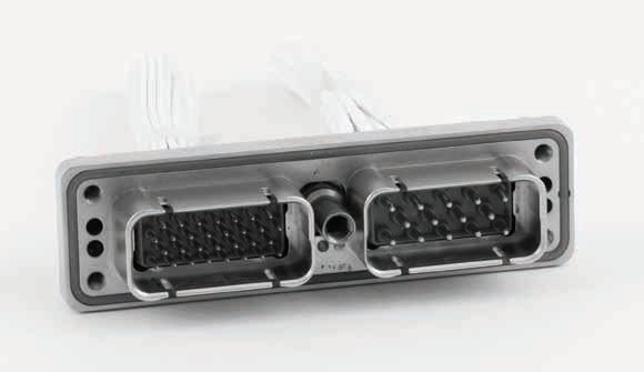
EPXB2 CONNECTORS
Radiall’s EPXB2 disconnect connectors have been widely used in the aerospace industry for more than 10 years � Meant to be used in cable-to-cable and PCB-to-cable applications, EPXB2 connectors exceed civil aerospace market expectations in terms of high density, quick installation, and cost and weight savings �
Standardized by EN4644 European standard, Radiall’s EPX® has been recognized as the leading rectangular modular connector and used in major commercial and business jet aircrafts EPXB2 connectors are designed to cover any applications including:
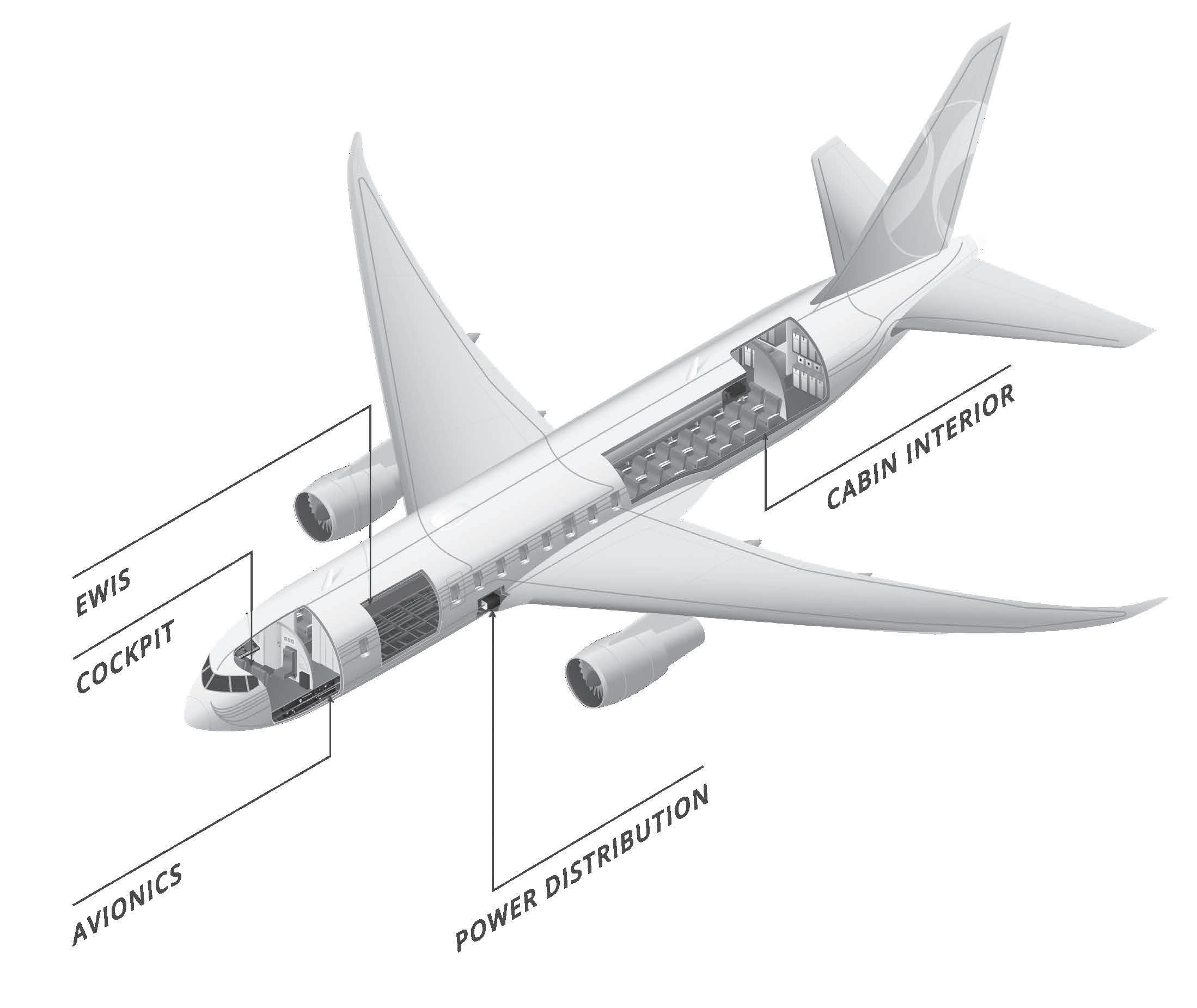
EWIS
EPXB2 provides easy maintenance and high reliability, which are key characteristics of EWIS environments �
AVIONICS
EPXB2's compactness, weight and robust design efficiently support avionics systems needs �
CABIN INTERIOR
EPXB2 combines high speed data with space savings to serve the latest generations of cabin systems �
POWER DISTRIBUTION
EPXB2's stackable and segregated features make it the perfect solution for power distribution�
COCKPIT
EPXB2 offers simplified and intuitive installation for Fiber Optic and signal connections that are critical in cockpit design�
1-34 | EPX SEr IES SIMPLIFICATION IS OUR INNOVATION Visit www.radiall.com for more information
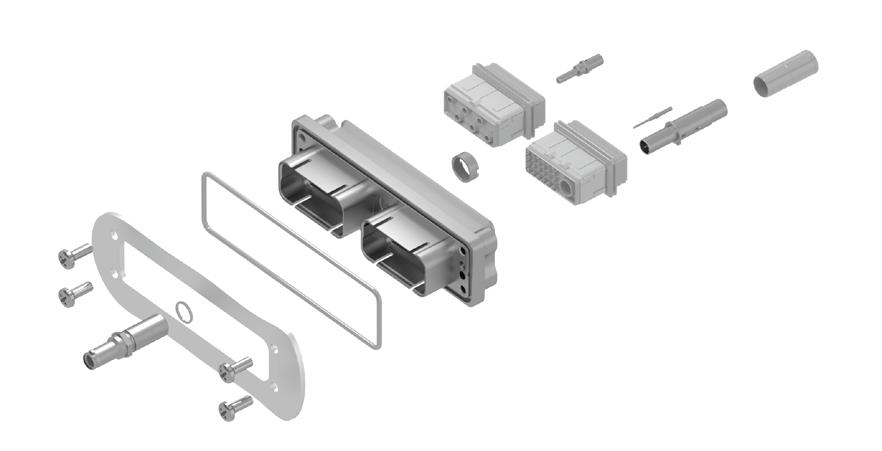
Disconnect Application
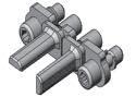
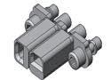
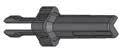
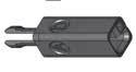
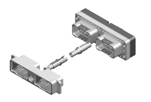
EPXB2 PRODUCT OVERVIEW
Detailed view of receptacle and plug with accessories for the EPXB2 disconnect connector:
Strain Relief
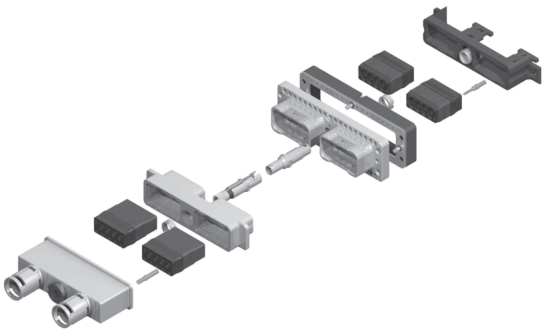
Shell
EPX SEr IES | 1-35 SIMPLIFICATION IS OUR INNOVATION Visit www.radiall.com for more information
Plug Shell
Jackscrew Locking Device Receptacle
Socket Contact
EMI Backshell
Inserts
Jacknut Locking Device
Ground Block Pin Contact
Disconnect Application
EPXB2 RANGE OVERVIEW
Modular and flexible, EPXB2 answers all disconnect connecting needs with the use of a limited number of components With a large variety of shells and one range of inserts, contacts and accessories, EPXB2 range is completely expandable and fits to your exact needs. You can mix and match solutions to build your connector with:


Defining connector types (plug or receptacle) and their key features.
1-36 | EPX SEr IES SIMPLIFICATION IS OUR INNOVATION Visit www.radiall.com for more information
M N N N N J J
M
N J
Aluminium Weight Optimized Aluminium
M N J
Flange Bulkhead Composite SHELL CLASSES - (ALL NICKEL-PLATED)
Receptacles
Plugs
Disconnect Application
EPXB2 LATEST INNOVATIONS
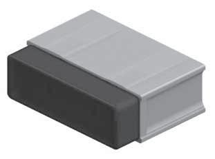
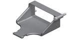
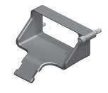
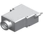
Radiall expands the EPX® series by offering iEPX, a new weight optimized EPXB2 shell designed to be used in disconnect panel applications With an integrated strain relief and EMI backshell to press-in, iEPX provides EMI shielding while reducing cost and weight
�
EPX® BULKHEAD
FEATURES & BENEFITS:
• Quick and easy to terminate
• Lightweight
• Prevents FOD
• Cable-to-cable connection
• Integrated strain relief
MIX & MATCH:
• Fully intermateable with all EPXB2 plugs and receptacles
• Modular and comprehensive range: iEPX uses all contacts and inserts from EPX® range�
Radiall’s EPXB2 Bulkhead receptacle is a perfect solution for disconnect panel sealing applications
� Combining EPX® proven technology with Bulkhead functionality, EPXB2 Bulkhead modular connectors provide effective panel sealing with a user friendly and cost saving approach�
With EPXB Bulkhead pin insert range, Bulkhead receptacle provides permanent sealing between two zones with different environmental conditions.
FEATURES & BENEFITS:
• Modular
• Competitive offer
• Optimized and mature design
• Easy and economical integration in the BOM
• PCB-to-cable or cable-to-cable connection
MIX & MATCH:
• Fully intermateable with all EPXB2 plugs
• Uses EPX® broad range of accessories and contacts including signal, power, quadrax and fiber optics
EPX SEr IES | 1-37 SIMPLIFICATION IS OUR INNOVATION Visit www.radiall.com for more information
iEPX
Disconnect Application
HOW TO ORDER EPXB2 SHELL
SERIES PREFIX
SHELL SIZE
B2: Two cavity shell
SHELL STYLE
For option compatibility, see the table below.
L: Receptacle with flange
H: Classic receptacle
Z: Receptacle with ground block
R: Receptacle without ground fingers
C: iEPX receptacle with integrated strain-relief
P: Classic plug
W: Plug with ground block
D: iEPX plug with integrated strain-relief
SHELL PLATING
N: Nickel-plated aluminium
M: Nickel-plated composite
J: Nickel-plated, weight-optimized aluminium
POLARIZATION CODE [2]
2: Polarizing device A to F delivered unassembled
3: Polarizing device N to Z delivered unassembled
LOCKING & POLARIZATION DEVICE [1]
1: Jackscrew
2: Jacknut
3: Without locking device
SHELL MOUNTING
A: Panel rear mounted connector with 4 ×
6-32 mounting holes
B: No mounting holes
D: Connector with 2 × Ø 3 �10 mm thru holes
F: Panel rear mounted connector with 2 ×
6-32 mounting holes
L: Panel rear mounted connector with 2 × 4-40 mounting holes
AVAILABLE SHELL MOUNTING
Class N (Aluminium)
Class J (Weight-Optimized Aluminium)
M (Composite)
Notes
1. Jackscrew/Jacknut can be mounted on either plug or receptacle shell. However, the standard options are: - Jackscrew for plug shells - Jacknut for receptacle shells
2. Please see page 1-40 for how to use the the polarization coding.
1-38 | EPX SEr IES SIMPLIFICATION IS OUR INNOVATION Visit www.radiall.com for more information
SHELL STYLE A (4 × 6.32 UNC) B (no holes) D (2 × Ø 3.10 mm) F (2 × 6.32 UNC) L (2 × 4.40 UNC)
L - - H - Z - -R - - -P - - W - -B - - -
H - - - - C - - - - P - - -D - - - -
L - - - P - -
Class
EPX
Disconnect Application
HOW TO ORDER EPXB2 ASSEMBLY KIT
Assembly kits are delivered fully assembled including shell with inserts mounted, with or without contacts, according to the selection. When selecting your insert codes, do not forget to place them in the order you want them assembled. Locking and polarizing devices are delivered uninstalled.
Tips to help you in your selection:
• You are free to use either pin or socket inserts in EPXB plug or receptacle
• Crimp contacts can be delivered with a kit Check which contacts will be included on page 1-10
• PC tail contacts can also be delivered with a kit Remember that only straight pin PC tail contacts are available, and in receptacle only
• If PC tail contacts are selected, then all cavities including signal, power and quadrax are populated Size 5 coax cavities are not populated�
All connector inserts will use the same insert class and the same contact termination.
EPX
SHELL SELECTION PA r T
SERIES PREFIX
SHELL SIZE
B2: Two cavity shell
SHELL STYLE
For option compatibly, see table on page 1-38
L: Receptacle with flange
H: Classic receptacle
Z: Receptacle with ground block
R: Receptacle without ground fingers
B: Bulkhead receptacle (bulkhead pin inserts compulsory)
C: iEPX receptacle with integrated strain-relief
P: Classic plug
W: Plug with ground block
D: iEPX plug with integrated strain-relief
SHELL MOUNTING
A: Rear panel mounted connector with 4 × 6-32 mounting holes
B: No mounting holes
D: Connector with 2 × Ø 3 10 mm thru holes
F: Rear panel mounted connector with 2 × 6-32 mounting holes
L: Rear panel mounted connector with 2 × 4-40 mounting holes
POLARIZATION
1: Jackscrew polarizing device A to F
2: Jacknut polarizing device A to F
3: Without locking device
6: Jackscrew polarizing device N to Z
7: Jacknut polarizing device N to Z
SHELL CLASS
N: Nickel-plated aluminium
M: Nickel-plated composite
J: Nickel-plated, weight-optimized aluminium
INSEr T SELECTION PA r T
CONTACTS TERMINATION
XS: Socket insert without contacts
XP: Pin insert without contacts
SS: Socket insert with crimp contacts [1]
SP: Pin insert with crimp contacts [1]
YA: Gold PC tail contacts length A [2] [3]
ZA: Tin-lead PC tail contacts length A [2] [3]
RA: Pure tin (RoHS) PC tail contacts length A [2] [3]
INSERT CODE
Refer to page 1-12 to select insert code
INSERT CLASS
B: Bulkhead insert with interfacial seal and rear grommet, available for pin insert only
E: Environmental
N: Non-environmental
H: Non-environmental insert with a rear grommet, available for pin insert only (recommended for crimp contact)
T: Non-environmental insert with an interfacial seal, available for pin insert only (recommended for PC tail contact)
Notes
1. These contacts are delivered uninstalled
2. Refer to pages 1-41 to select PC tail contacts for receptacle.
3. Not available with iEPX
EPX SEr IES | 1-39 SIMPLIFICATION IS OUR INNOVATION Visit www.radiall.com for more information
Disconnect Application
CODE

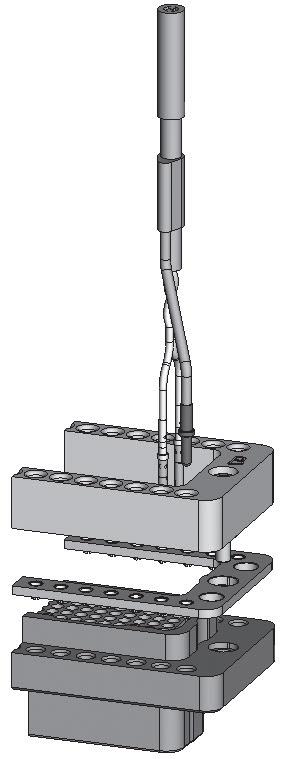
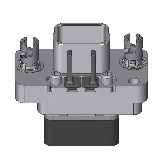
As a standard, jackscrews are installed in plugs, and jacknuts are installed in receptacle shells; however, they both can be installed in either plugs and receptacles. The nut can be fixed with your automatic screwdriver and the tool bit we provide (P/N 282664)�
Avec point de polarization version market
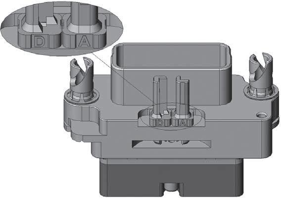
Tip: Use the shell reference mark (located at the top of the locking cavity) to choose keying position.
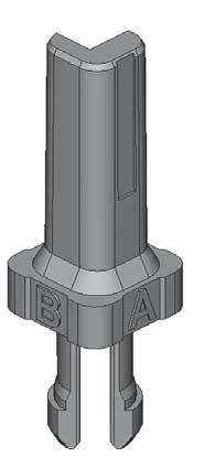
Polarization Devices
CODING DANS BOITIER FEMELLE
Avec point de polarization version market
Shell Reference Mark
CODING DANS BOITIER FEMELLE
CODING DANS BOITIER FEMELLE
Avec point de polarization version market
CODING DANS BOITIER FEMELLE
CODING DANS BOITIER MALE Avec
CODING DANS BOITIER MALE
Avec point de polarization version market
CODING DANS BOITIER FEMELLE
CODING DANS BOITIER MALE
Avec point de polarization version market
CODING DANS BOITIER FEMELLE

CODING DANS BOITIER FEMELLE
CODING DANS BOITIER MALE
CODING DANS BOITIER MALE
Avec point de polarization version market
CODING DANS BOITIER FEMELLE
CODING DANS BOITIER MALE
CODING DANS BOITIER MALE
Shell Reference Mark
CODING DANS BOITIER MALE

1-40 | EPX SEr IES SIMPLIFICATION IS OUR INNOVATION Visit www.radiall.com for more information
STANDARD
From A to F 617980029 617980066 From N to Z 617980028 617980067 Universal 617980022
From A to F 617980012
From N to Z 617980013 N/A Universal 617980023 N/A B C D E F A F E D C B A N R Z Y X W R N Z Y W
EPXB2 POLARIZATION
KEYING POSITION AVAILABLE AS RECEPTACLE PLUG
BULKHEAD Jacknut
N/A Jackscrew
N/A
Avec point
polarization version market B C D E F A F E D C B A N R Z Y X W R N Z Y W
de
polarization
market B C D E F A E D C B N R Z Y X W R N Z Y W X
point de
version
B C D E F A F E D C B A N R Z Y X W R N Z Y W X
B C D E F A F E D C B N R Z Y X W R N Z Y W X
B C D E F A F E D C B A N R Z Y X W R N Z Y W X
B C D E F A F E D C B A N R Z Y X W R N Z Y W X
B C E F A F E D C B A N R Z Y X W R N W X
Disconnect Application
CONTACTS TERMINATION FOR RECEPTACLES
EPXB2 COMPOSITE SHELL
20 (0 755)
EPXB2 WEIGHT OPTIMIZED ALUMINIUM AND ALUMINIUM SHELL
55 (0 572)
75 (0 698)
GROUND BLOCK
Insulator
Connector Shell
Notes
1. These PC tail lengths are not compatible with EPXBE, EPXBH or EPXBB inserts. STRAIGHT PC TAIL
Radiall provides a unique patented feature by integrating a ground block directly on the shell� This option permits very short ground terminations �
M39029/1-101 Contacts Radiall P/N 617221050
Intermediate Plate for Grounding
EPX SEr IES | 1-41 SIMPLIFICATION IS OUR INNOVATION Visit www.radiall.com for more information
TERMINATION MIN
MIN LENGTH
MM
GOLD TIN-LEAD PURE TIN (ROHS) 14
- YA ZA RA 17
- YB ZB RB 19
- YC ZC RC 23
YD ZD RD
CONTACT
LENGTH E MM (INCH)
H
(INCH)
� 20 (0� 559) [1]
35 (0 683) [1]
[1]
10 (0 909) 5 40 (0 212)
STRAIGHT PC TAIL CONTACT TERMINATION MIN LENGTH E MM (INCH) MIN LENGTH H MM (INCH) GOLD TIN-LEAD PURE TIN (ROHS) 14
- YA ZA RA 17
- YB ZB RB 19
YC ZC RC 23
40
212) YD ZD RD H E
[1]
[1]
55 (0 769) [1] -
50 (0 925) 5
(0
Disconnect Application
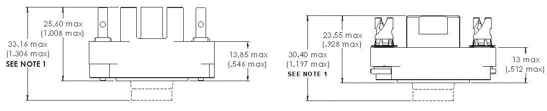
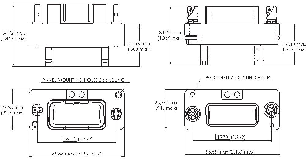
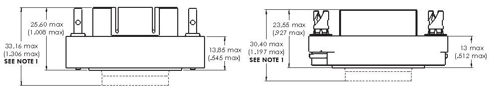
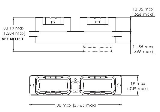
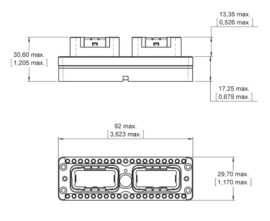
EPXB2 ALUMINIUM SHELL DIMENSIONS
CLASS N&J
CLASSIC GROUND BLOCK
[HL]
CLASS N
[ZA]
BULKHEAD
[BA]
Notes
1. For insert with grommet: maximum dimension is the one shown in the drawing. For insert without grommet: insert is flush to the shell. Maximum dimension for the receptacle is 25.55 mm (1.006 in.) and for the plug is 23.52 mm (0.926 in.) . For insert with optical contacts: the maximum dimension for the receptacle is 38.70 mm (1.524 in.) and for the plug is 36.00 mm (1.418 in.).
1-42 | EPX SEr IES SIMPLIFICATION IS OUR INNOVATION Visit www.radiall.com for more information
1,083 max. 27,50 max. 3,701 max. 94 max. 3,228 82 0,630 16 0,656 max. 16,65 max. 0,526 max. 13,35 max.
max. 33,10 max. NOTE 1
1,304
Receptacle
Plug [PB]
Receptacle
Plug [WA]
Receptacle
Disconnect Application
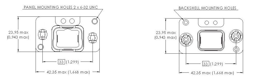
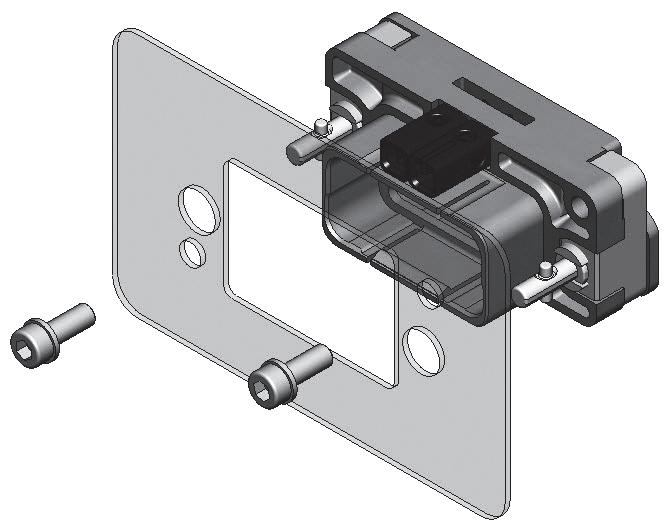
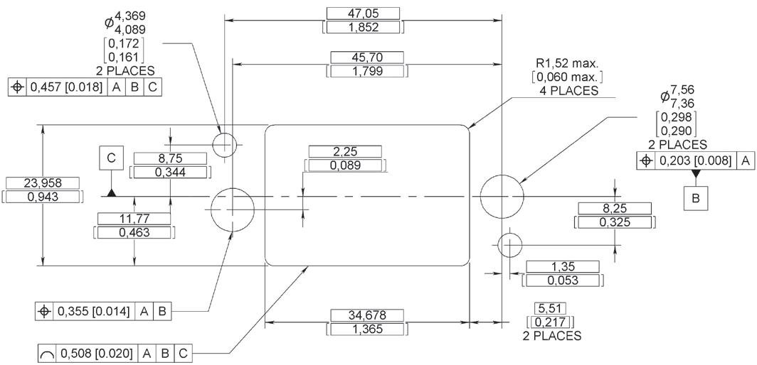
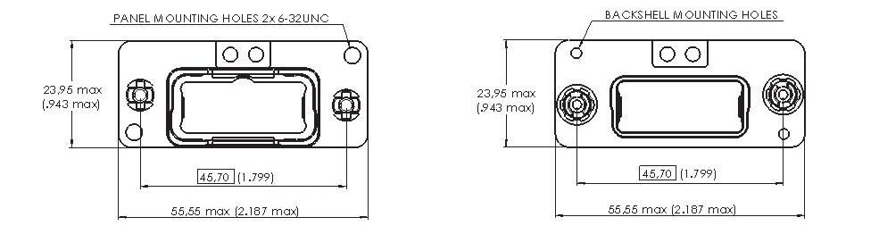
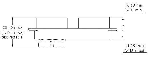
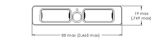
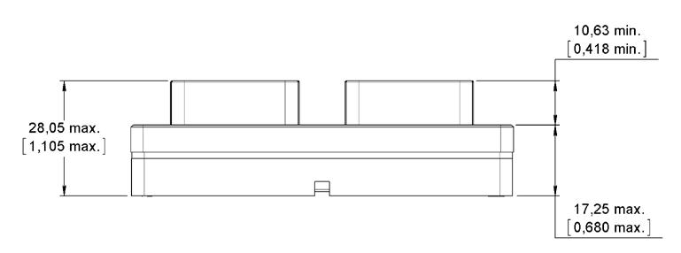
EPXB2 ALUMINIUM SHELL DIMENSIONS
CLASS J
Receptacle [CL]
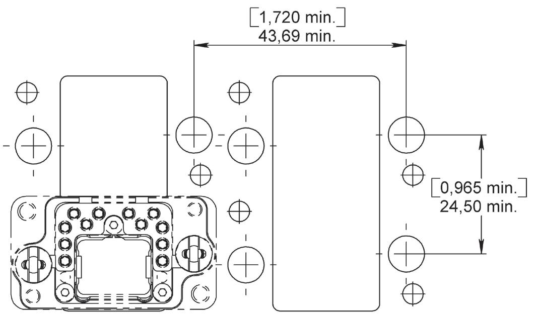
SINGLE PANEL CUT-OUT
CLASS N & J
Shell Mounting Code D, F and L
CLASS N - BULKHEAD RECEPTACLE
Shell Mounting Code A
MULTIPLE PANEL CUT-OUT
Plug [DB]
Shell Mounting Code A
Notes
1. For insert with grommet: maximum dimension is the one shown in the drawing. For insert without grommet: insert is flush to the shell. Maximum dimension for the receptacle is 25.55 mm (1.006
EPX SEr IES | 1-43 SIMPLIFICATION IS OUR INNOVATION Visit www.radiall.com for more information
3.465 max. 88 max. 0.748 max. 19 max. 0.382 max. 9.7 max. 0.526 max. 13.35 max. 0.429 max. 10.90 max. 1.451 max. 36.85 max. 1.304 max. 33,10 max. NOTE 1 3.150 max. 80 max. 0.748 max. 19 max. 0.382 max. 9.70 max. 0.419 min. 10.64 min. 1.451 max. 36.85 max. 0.846 max. 21.50 max. 1.197 max. 30.40 max. NOTE 1 3.150 max. 80 max. 0.748 max. 19 max. 0.382 max. 9.70 max. 0.419 min. 10.64 min. 1.451 max. 36.85 max. 0.846 max. 21.50 max. 1.197 max. 30.40 max. NOTE 1
in.) and for the plug is 23.52 mm (0.926 in.).
contacts:
maximum dimension for
receptacle is 38.70 mm (1.524 in.) and for the plug is 36.00 mm (1.418 in.).
For insert with optical
the
the
0,768 19,50 76.30 ±0.10 3.004 ±0.004 17.35 ±0.10 0.683 ±0.004 41 1.614 41 1.614 8 0.315 8 0.315 4 x R3.50 max. 0.138 max. 4 holes for mounting screws Ø4.50 [0.177] max 0.10 A B P A B 0.8 P - To ensure the sealing performance, the panel has to be dimensioned by the customer in accordance to MI AC 17 00008
iEPX
N
CLASS
& J
Disconnect Application
EPXB2 COMPOSITE SHELL DIMENSIONS CLASS M
SINGLE PANEL CUT-OUT
Shell Mounting Code D and L
MULTIPLE PANEL CUT-OUT
Notes
1. For insert with grommet (EPXBE and EPXBH): maximum dimension is the one shown in the drawing. For insert without grommet (EPXBN): is flush to the shell. Maximum dimension for the receptacle is 25.55 mm (1.006 in.) and for the plug is 23.52 mm (0.926 in.).
For inserts with optical contacts: the maximum dimension for the receptacle is 38.70 mm (1.524 in.) and the plug is 36.00 mm (1.418 in.).
1-44 | EPX SEr IES SIMPLIFICATION IS OUR INNOVATION Visit www.radiall.com for more information
0,768 19,50 1,008 25,60 ClicktoBUYNOW!PDC e d wwe co ClicktoBUYNOW!PDC e d wwe co
Receptacle [LL]
Plug [PB]
Disconnect Application
EPXB2 WEIGHTS
Weights include the shell with no polarization If locking is needed, please add the following weights:
• Jackscrew: 9�0 g
• Jacknut: 7 8 g
• Bulkhead Jacknut: 8 �7 g
EPX SEr IES | 1-45 SIMPLIFICATION IS OUR INNOVATION Visit www.radiall.com for more information
CLASS
A B D F L SHELL
Class N L - - 45 g (1 59 oz) 45 g (1 59 oz) 45 g (1 59 oz) H - 35 g (1 23 oz) 36 g (1 27 oz) 36 g (1 27 oz) 36 g (1 27 oz) Z 80 g (2 � 82 oz) 80 g (2 � 82 oz) - -R 45 g (1 59 oz) - - -P - 30 g (1 06 oz) 30 g (1 06 oz) - 30 g (1 06 oz) W 75 g (2 65 oz) 75 g (2 65 oz) - -B 50 g (1 76 oz) - - -Class J H - - - - 27 g (0 95 oz) C - - - - 35 g (1� 23 oz) P - 25 g (0 88 oz) - -D - 30 g (1 06 oz) - -Class M L - - 35 g (1 23 oz) - 35 g (1 23 oz) P - 24 g (0 85 oz) 25 g (0 88 oz) - 25 g (0 88 oz)
SHELL MOUNTING
STYLE
Rack & Panel Application
PART NUMBER
617922007
617922014
617928100
617925069
617925052
617925054
Notes
1. Not compatible with jackscrew
617922029
DESCRIPTION
Straight Strain Relief (Composite)
Straight Strain Relief for Fiber Optic Cable (Anodized Aluminium)
Straight EMI Backshell (Nickel-Plated Composite)
Short Straight EMI Backshell (Nickel-Plated Composite)
EMI Backshell for Braid Shield Termination (Nickel-Plated Aluminium)
EMI Backshell For Screened Twisted Pair Cables (Nickel-Plated Aluminium)
Backshell for Large Sized Wire Harnesses (Nickel-Plated Aluminium) [1]
EMI Backshell for iEPX Connectors (Composite)
Fiber Optic Backshell (Composite)
1-46 | EPX SEr IES SIMPLIFICATION IS OUR INNOVATION Visit www.radiall.com for more information
EPXB2 ACCESSORIES
Rack & Panel Application
EPXB2 SPARE PARTS
PART NUMBER
617954101
617980029
617980028
DESCRIPTION
Grounding Spring (For EPXB2 Aluminium Only)
Jacknut – A/B/C/D/E/F
Jacknut – N/R/W/X/Y/Z
617980022 Universal Jacknut
617980066
617980067
617980012
617980013
Bulkhead Jacknut – A/B/C/D/E/F
Bulkhead Jacknut – N/R/W/X/Y/Z
Jackscrew – A/B/C/D/E/F
Jackscrew – N/R/W/X/Y/Z
617980023 Universal Jackscrew
617954002
617954003
617954004
617954005
617929023
Dust Cap for Plug Shell (Pink Color)
Dust Cap for Receptacle Shell (Pink Color)
ESD Dust Cap Plug Shell (Black Color)
ESD Dust Cap Receptacle Shell (Black Color)
Sealing Inserts for Fly Away Applications: Mateable with Pin Insert
617929022
Sealing Inserts for Fly Away Applications: Mateable with Socket Insert
EPX SEr IES | 1-47 SIMPLIFICATION IS OUR INNOVATION Visit www.radiall.com for more information
Rack & Panel Application
DISCONNECT TOOLS
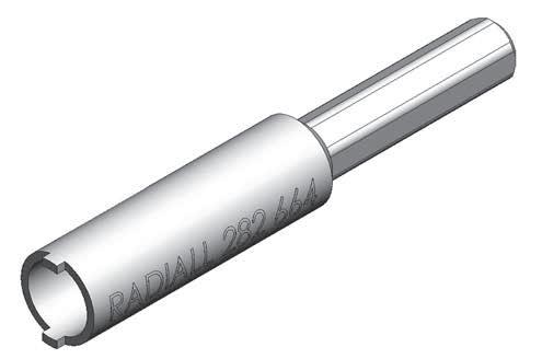

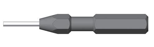
282664
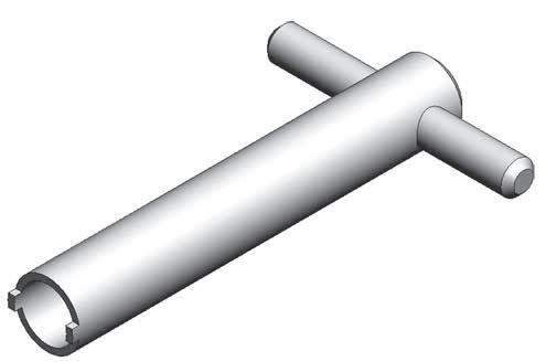
282665
1/4 in Hex Screwdriver Bit to Affix the Nut of the Jackscrew or the Jacknut to the EPXB2 Accessories
Spigot Wrench to Affix the Nut of the Jackscrew or the Jacknut to the EPXB2 Accessories
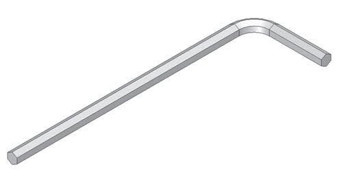
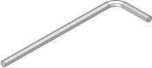
Allen Wrench for 1/4 turn Fasterner (3/32 in �)
282666002 Allen Wrench for Rear Accessories (5/64 in )
Allen Wrench for Jackscrew (9/64 in )
1-48 | EPX SEr IES SIMPLIFICATION IS OUR INNOVATION Visit www.radiall.com for more information
DESCRIPTION TO BE USED WITH EPXA1 EPXB1 EPXB2
PART NUMBER
- -
- -
282666
-
- -
282666001
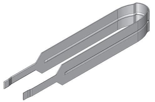
- - 282521002 Insert Extraction Tool - 282521004 Right Angle Insert Extraction Tool - 282521007 Bulkhead Insert Extraction Tool - - 282521005 Insert Extraction Tool -617954020 Plastic Box to Protect Wired Inserts during Handling F780855000 Hexagonal
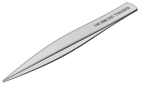
- 282668001 Tweezers
Change Polarizing Posts and Keys - -
Key 2 mm (5/64 in ) Flats for Sleeve Holder Removal
to
Rack & Panel Application
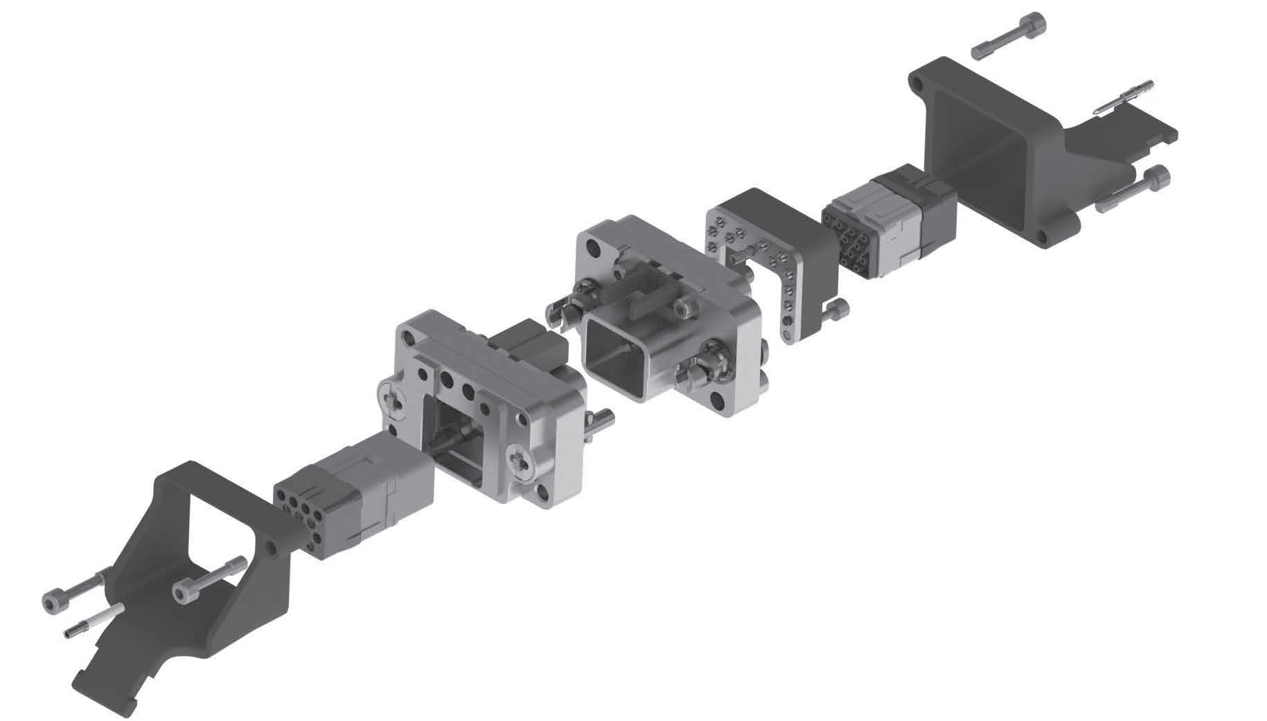
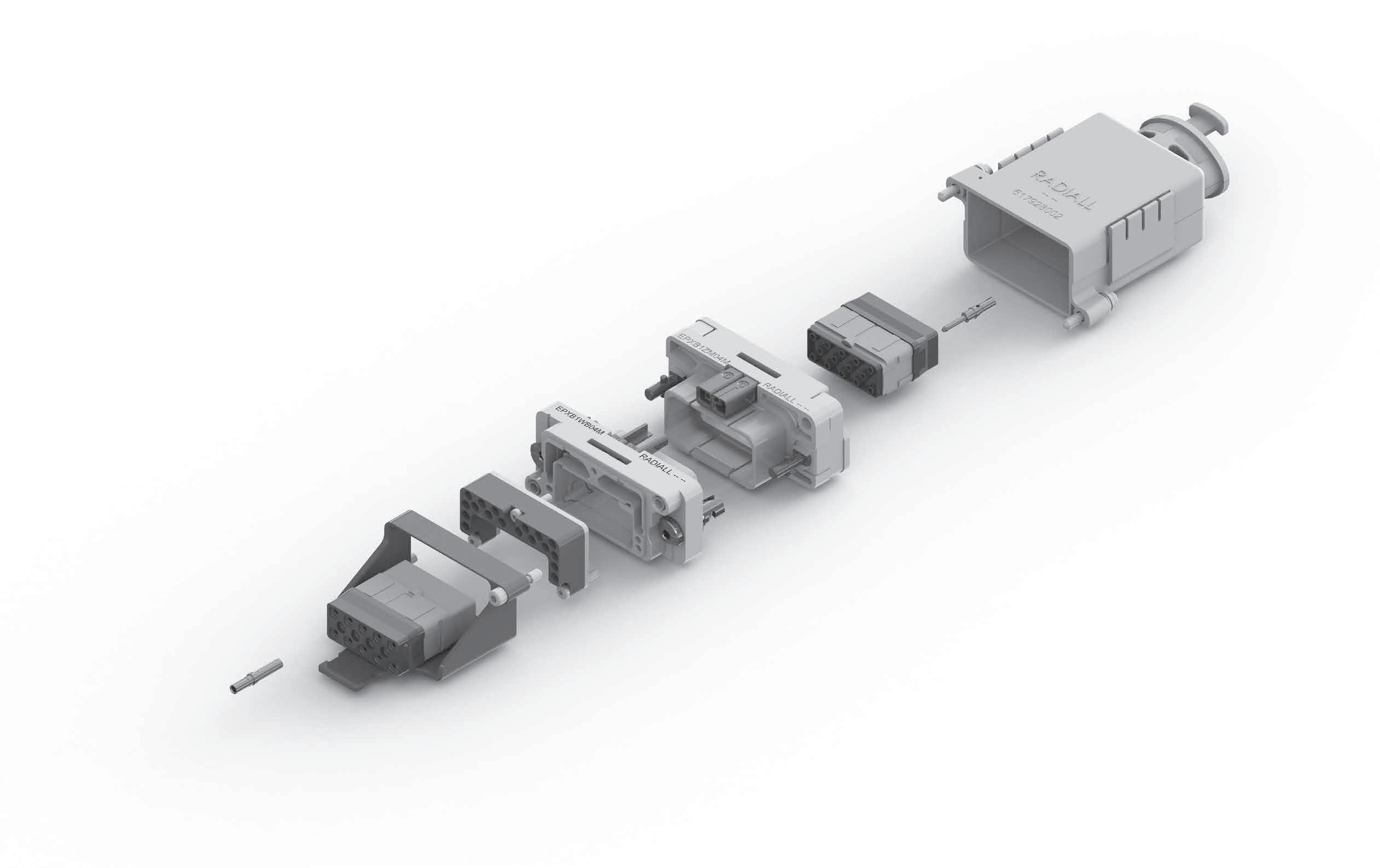
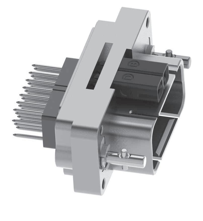
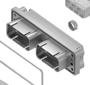
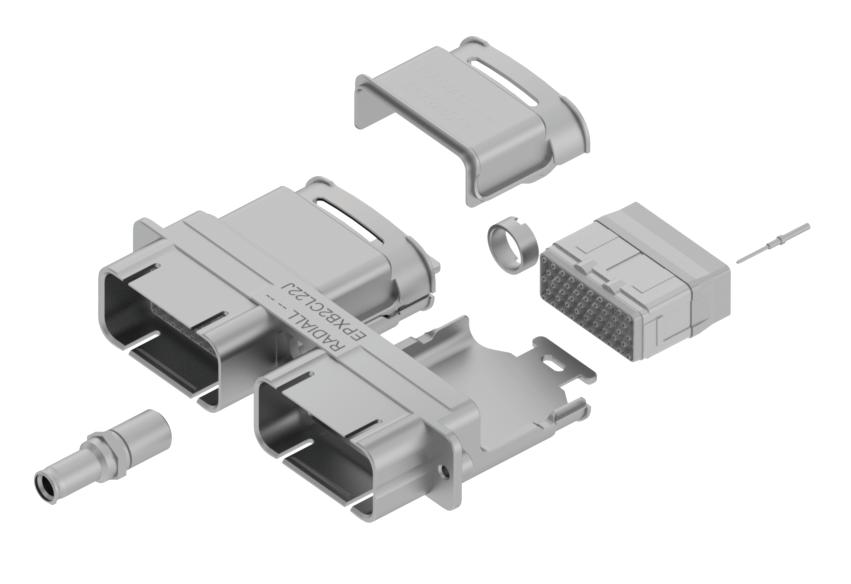
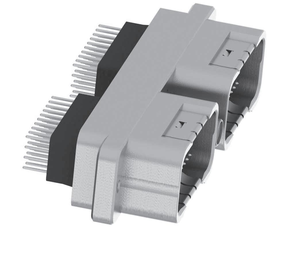
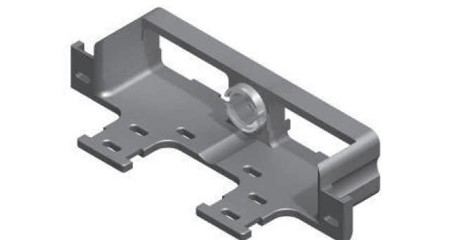
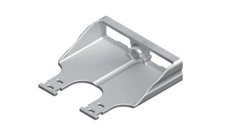
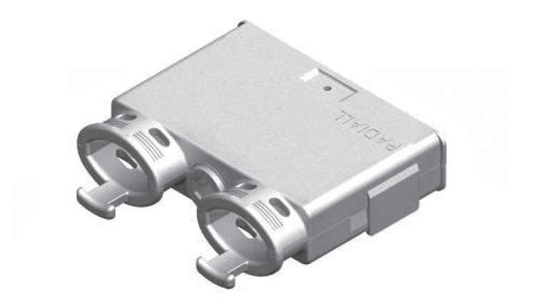
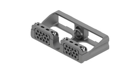
EPXB3 PRODUCT OVERVIEW
Detailed View of Receptacle and Plug with Accessories for the EPXB3 Rack & Panel Connector:
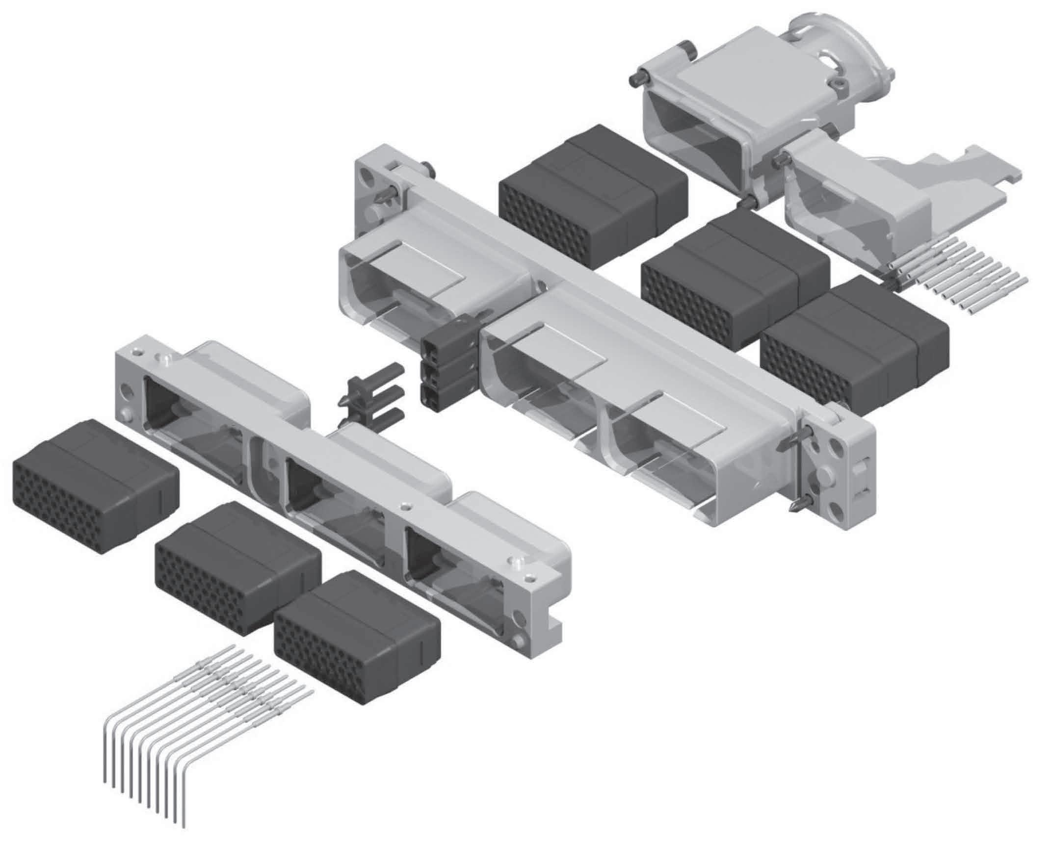
Fixed or Floating Device
EPX SEr IES | 1-49 SIMPLIFICATION IS OUR INNOVATION Visit www.radiall.com for more information
EMI Backshell
Strain Relief
Crimp Contacts
Plug Shell
Right Angle or Straight PC Tail Contacts
Receptacle Shell
Polarization Hardware
Inserts
Rack & Panel Application
HOW TO ORDER EPXB1, B2, B3 & B4 SHELL
SERIES PREFIX
SHELL SIZE
B1: One cavity shell
B2: Two cavity shell
B3: Three cavity shell
B4: Four cavity shell
SHELL STYLE
P: Plug, nickel-plated
R: Receptacle, nickel-plated
SHELL MOUNTING
(refer to page 1-52 for codes)
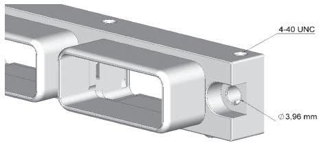
M: Plug, fixed connector with Ø 3 �96 mm holes and 4-40 UNC on side
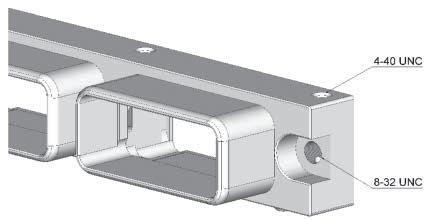
N: Plug, fixed connector with 8-32 UNC and 4-40 UNC on side
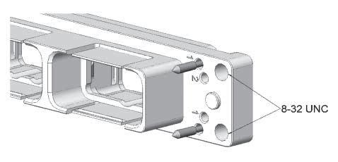
S: Plug or Receptacle, fixed with 4 × 8-32 UNC
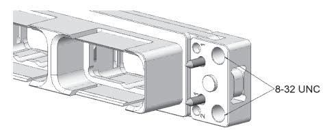
T: Receptacle, floating with 4 × 8-32 UNC (two axes) [1]
POLARIZATION CODE
1: Shell delivered with polarizing keys unassembled
2: Shell delivered with no polarizing keys
PANEL CUT-OUT CODING
A TO Z: Receptacle, refer to page 1-54 for the code selection
0 (ZERO): Plug, no panel cut-out coding
Notes
1. This floating option is not available in EPXB4 version.
1-50 | EPX SEr IES SIMPLIFICATION IS OUR INNOVATION Visit www.radiall.com for more information
EPX
Rack & Panel Application
HOW TO ORDER EPXB1, EPXB2, B3 & B4 ASSEMBLY KIT FOR LRM
Assembly kit is delivered fully assembled including shell with inserts mounted, with or without contacts according to the selection. When selecting your insert codes, do not forget to place them in the order you want them assembled. Polarization hardware are always provided unassembled with assembly kits.
Tips to help you in your selection:
• You are free to use either pin or socket inserts in EPXB plug or receptacle�
• Crimp contacts can be delivered with a kit � Check which contacts will be included on page 1-10�
• If PC tail contacts are selected then all cavities including signal, power and quadrax are populated� Size 5 coax cavities are not populated�
• If PC tail contacts are needed, remember that only straight pin PC tail contacts are available, and in plug only�
All connector inserts will use the same insert class and the same contact termination.
SHELL SELECTION PA r T
SERIES PREFIX
SHELL SIZE
B1: One cavity shell
B2: Two cavity shell
B3: Three cavity shell
B4: Four cavity shell
SHELL STYLE
P: Plug, nickel-plated
R: Receptacle, nickel-plated
SHELL MOUNTING
(refer to page 1-52 for codes)
M: Plug, fixed connector with Ø 3 �96 mm holes and 4-40 UNC on side
N: Plug, fixed connector with 8-32 UNC and 4-40 UNC on side
S: Plug or Receptacle, fixed with 4 × 8-32 UNC
T: Receptacle, floating with 4 × 8-32 UNC (two axes) [1]
PANEL CUT-OUT CODING
A TO Z: For receptacle, refer to page 1-54 for the code selection
0 (ZERO): For plug, no panel cut-out coding
Notes
1. This floating option is not available in EPXB4 version
2. These contacts are delivered uninstalled
3. Refer to page 1-53 to select PC tail contacts for plug
INSEr T SELECTION PA r T
CONTACTS TERMINATION
XS: Female insert without contacts
XP: Male insert without contacts
SS: Female insert with crimp contacts [2]
SP: Male insert with crimp contacts [2]
YA: Gold PC tail contacts length A [3]
ZA: Tin-lead PC tail contacts length A [3]
RA: Pure tin (RoHS) PC tail contacts length A [3]
INSERT CODE
Refer to page 1-10 to select insert code
INSERT CLASS
E: Environmental
N: Non-environmental (no rear grommet, no interfacial seal)
H: Non-environmental insert with a rear grommet (recommended for crimp contact)
T: Non-environmental insert with interfacial seal (recommended for PC tail contact)
EPX SEr IES | 1-51 SIMPLIFICATION IS OUR INNOVATION Visit www.radiall.com for more information
EPX
Rack & Panel Application
EPXB SHELL MOUNTING
Fixed Connector with Ø 3 96 mm Holes and 4-40 UNC Front or Side Mount
Connector with 8-32 UNC and 4-40 UNC Front or Side Mount
Fixed with 4 × 8-32 UNC Panel Rear Mount
Floating with 4 × 8-32 UNC Panel Rear Mount
1-52 | EPX SEr IES SIMPLIFICATION IS OUR INNOVATION Visit www.radiall.com for more information
RECEPTACLE
CODE PLUG
N/A M N/A N S N/A T N/A
SIDE
SIDES
Rack & Panel Application
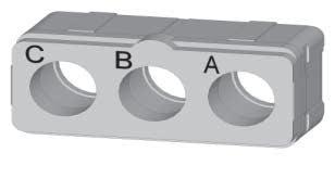
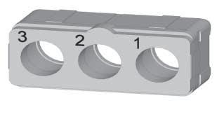
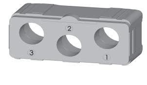
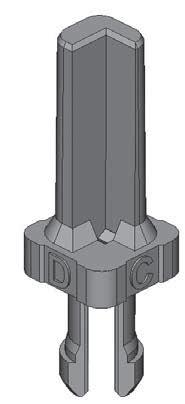
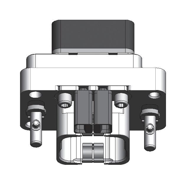
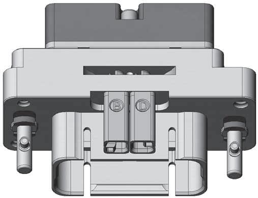
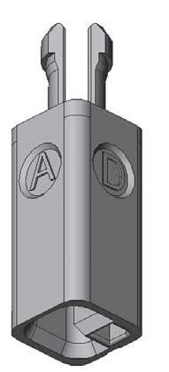
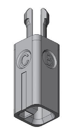
EPXB POLARIZATION CODE
A polarization device is included in the part number and should be installed as shown below Each shell has three polarization hardware, which can be in four different positions. Each polarization hardware can have its own position; this allows a large range of codification.

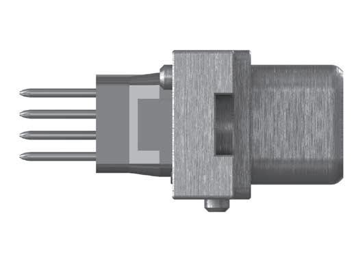
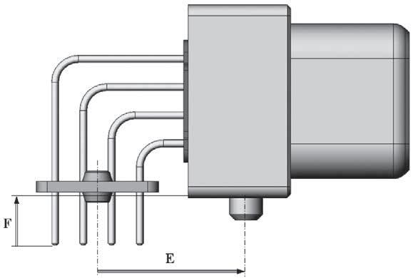
CONTACT TERMINATIONS
2
EPX SEr IES | 1-53 SIMPLIFICATION IS OUR INNOVATION Visit www.radiall.com for more information
STRAIGHT PC TAIL CONTACT TERMINATION MINI LENGTH E MM (INCH) MINI LENGTH H MM (INCH) GOLD TIN-LEAD PURE TIN (ROHS) 10 60 (0 417) [1] - YA ZA RA 13 80 (0 543) [1] - YB ZB RB 15 60 (0 614) [1] - YC ZC RC 19 55 (0 769) 5 40 (0 212) YD ZD RD RIGHT ANGLE PC TAIL CONTACT TERMINATION MINI LENGTH F MM (INCH) MINI LENGTH E MM (INCH) GOLD TIN-LEAD PURE TIN (ROHS)
20 (0 086) 12 85 (0 505) [1] GA LA TA
60 (0 141) 20 10 (0 791) GB LB TB
60 (0 141) 12 85 (0 505) [1] GC LC TC
20 (0 141) 20 10 (0 791) GD LD TD Notes
EPXBE
EPXBH
3
3
2
1. These PC tail lengths are not compatible with
and
inserts
FOR EPXB1, EPXB2, EPXB3 AND EPXB4
H E E F
PLUGS
Polarization
1 1 2 2 3 3
Connectors are shown front side with cavity A upwards. PLUG SIZE 3 Polarization Post RECEPTACLE SIZE 3
Key
Rack & Panel Application
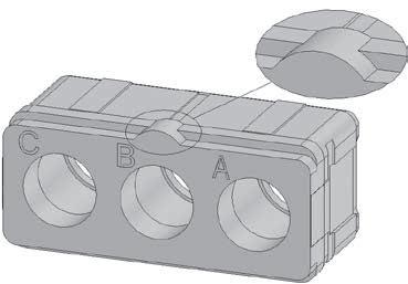
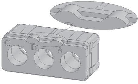
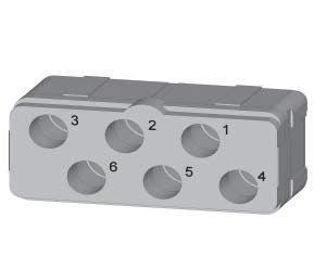
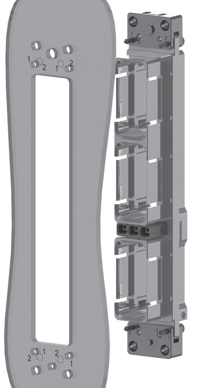
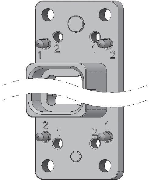
EPXB PANEL CUT-OUT CODING
When several connectors are used with the same equipment, coding is available on the shell to correlate the correct shell with the correct panel cut-out �
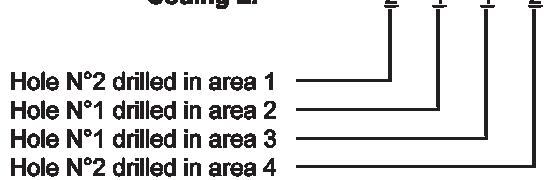
On the panel cut-out, four areas are coded: area 1, 2, 3 and 4 (see figure below). For each area, one of the two holes should be drilled (hole n°1 or hole n°2) Each hole on the panel cut-out corresponds to the use of a coding pin on the shell�
CODING PINS ARE FOR RECEPTACLE ONLY.
Notes
1. Z panel cut-out coding is only available with fix mounting.
1-54 | EPX SEr IES SIMPLIFICATION IS OUR INNOVATION Visit www.radiall.com for more information
CODING PANEL HOLE NUMBER TO DRILL IN AREA 1 PANEL HOLE NUMBER TO DRILL IN AREA 2 PANEL HOLE NUMBER TO DRILL IN AREA 3 PANEL HOLE NUMBER TO DRILL IN AREA 4 A
B 1 1 1 1 C 1 1 1 2 D 1 1 2 1 E 1 1 2 2 F 1 2 1 1 G 1 2 1 2 H 1 2 2 1 J 1 2 2 2 K 2 1 1 1 L 2 1 1 2 M 2 1 2 1 N 2 1 2 2 P 2 2 1 1 R 2 2 1 2 S 2 2 2 1 T 2 2 2 2 Z Connector Delivered Without Coding Pin [1] Area 1 Area 2 Area 3 Area 4 2 1 1 2 Coding L:
PANEL CUT-OUT
Connector Delivered With Coding Device Uninstalled
Rack & Panel Application
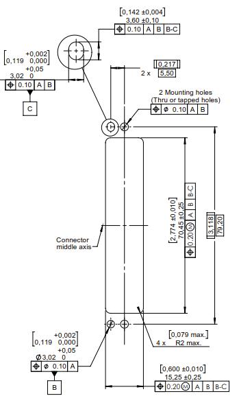
EPXB1 SHELL DIMENSIONS & PANEL CUT-OUTS
RECEPTACLE
Floating Mount Fixed Mount
PANEL CUT-OUTS
Receptacle - Shown from the Rear Side
PLUG
Plug - Shown from the Front Side
EPX SEr IES | 1-55 SIMPLIFICATION IS OUR INNOVATION Visit www.radiall.com for more information
Rack & Panel Application
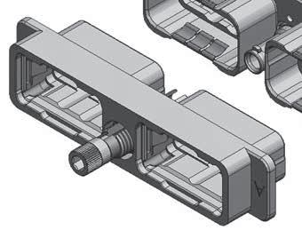
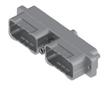
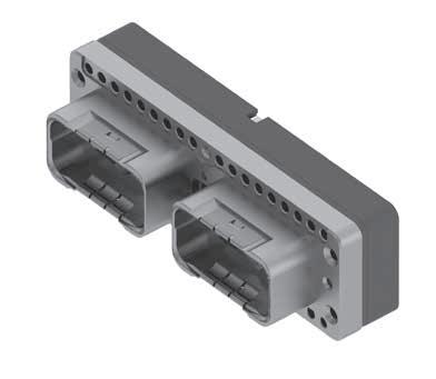
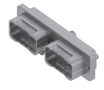
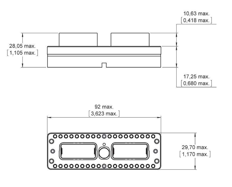
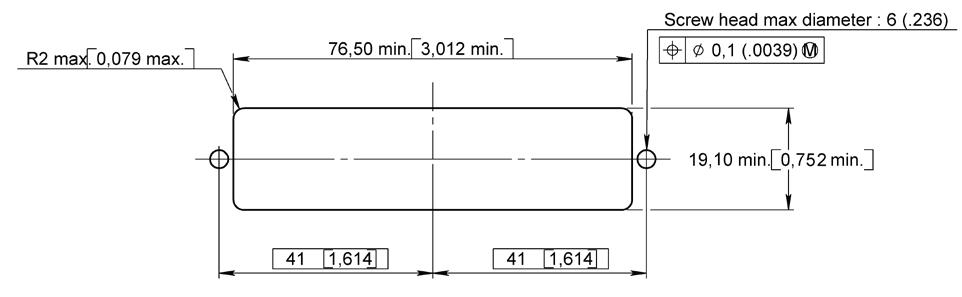
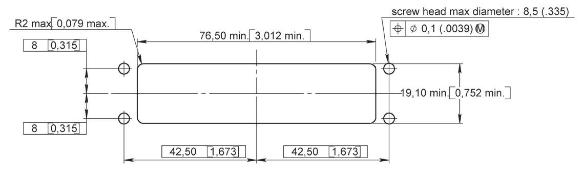
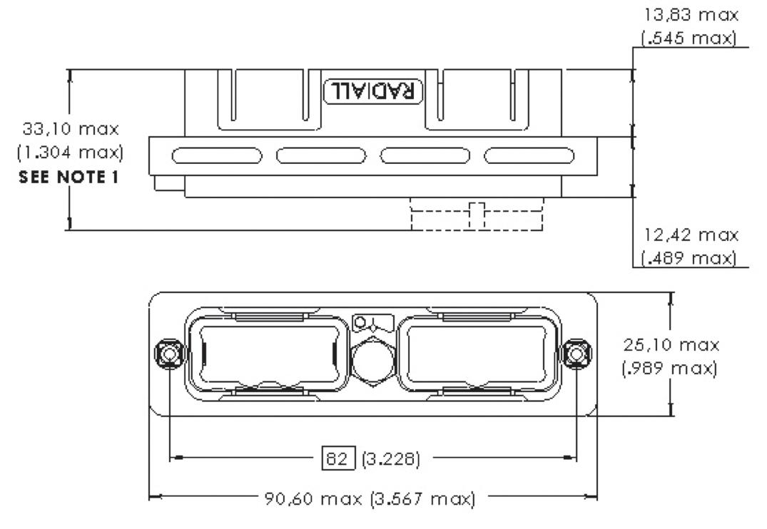
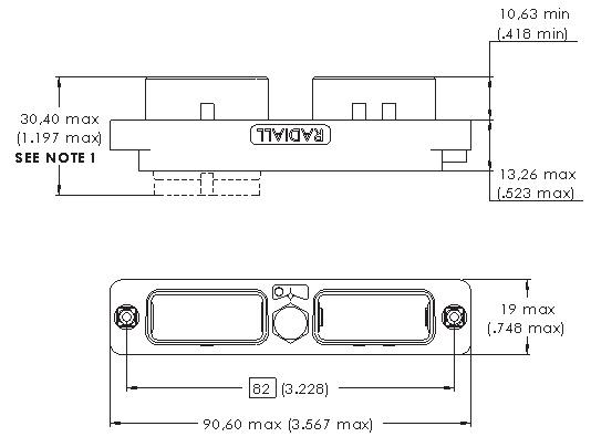
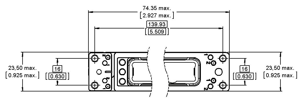
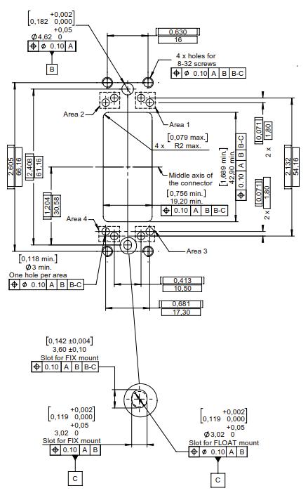
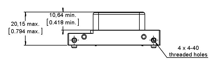
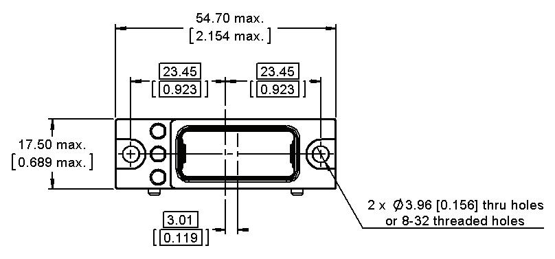
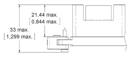
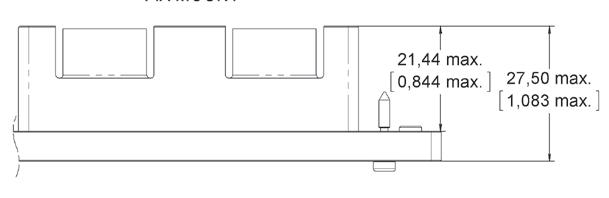
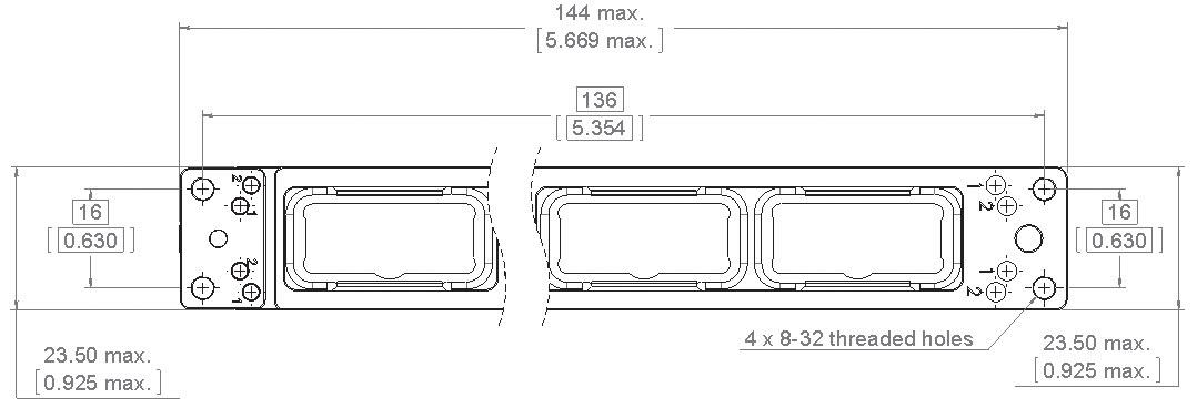
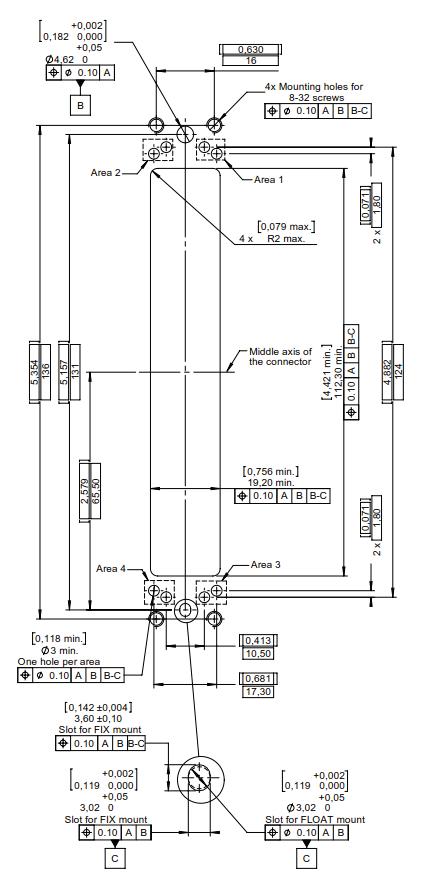
EPXB2 SHELL DIMENSIONS & PANEL CUT-OUTS
RECEPTACLE
PANEL CUT-OUTS
Receptacle - Shown from the Rear Side
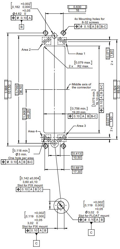
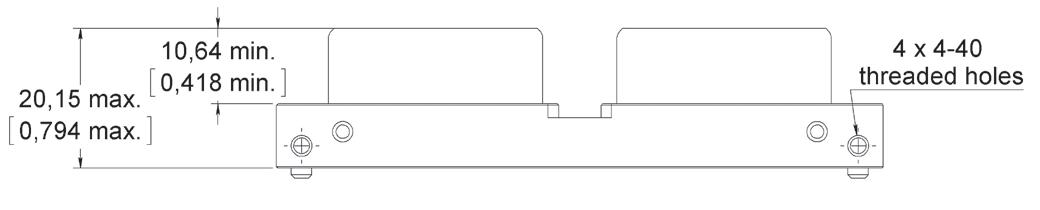
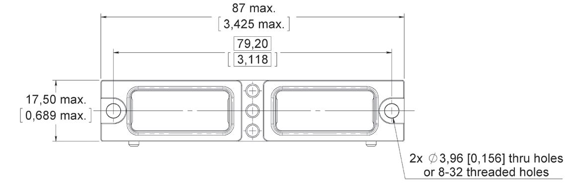
Plug - Shown from the Front Side
1-56 | EPX SEr IES SIMPLIFICATION IS OUR INNOVATION Visit www.radiall.com for more information
Floating Mount
Fixed Mount
PLUG
Rack & Panel Application
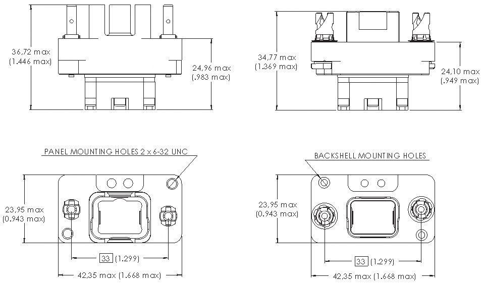
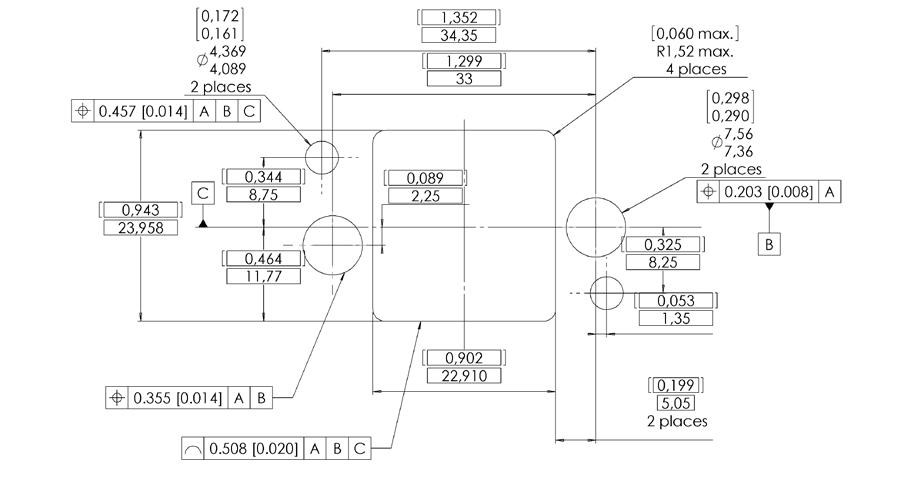
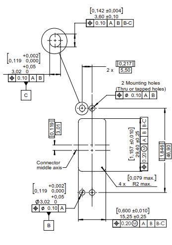
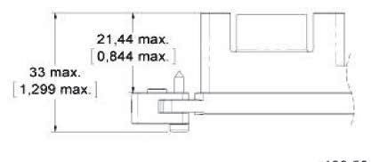
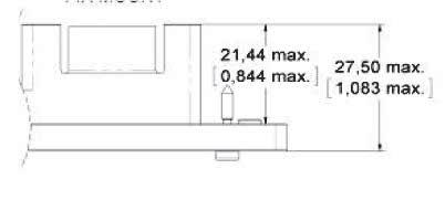
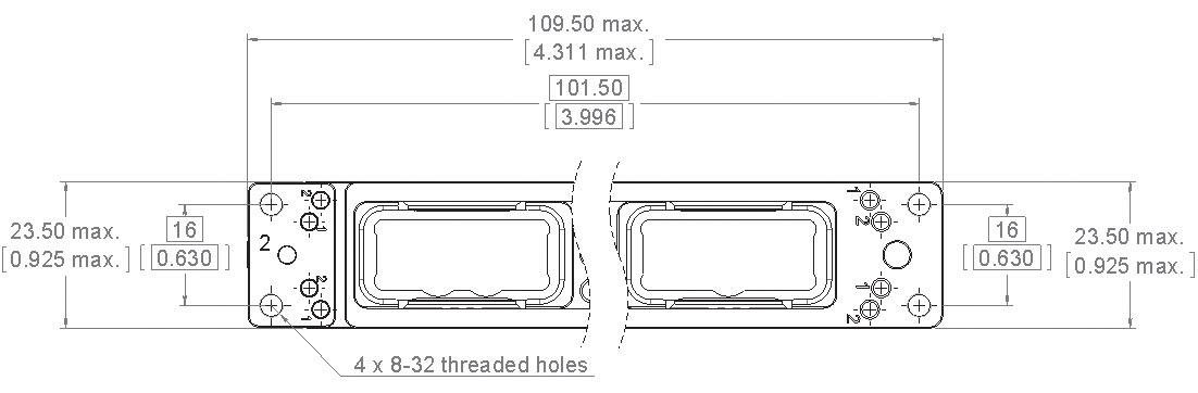
EPXB3 SHELL DIMENSIONS & PANEL CUT-OUTS
RECEPTACLE
PANEL CUT-OUTS
Receptacle - Shown from the Rear Side
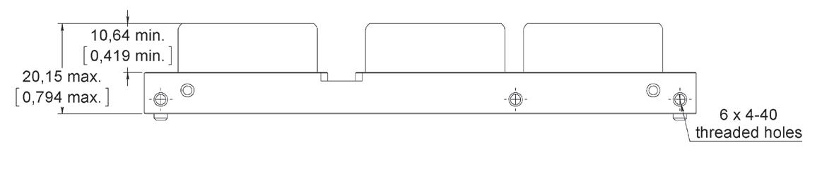
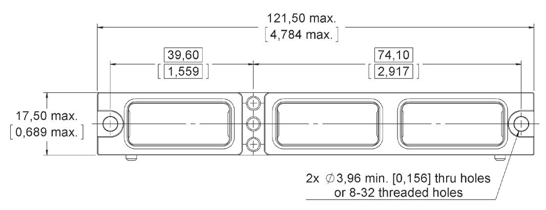
Plug - Shown from the Front Side
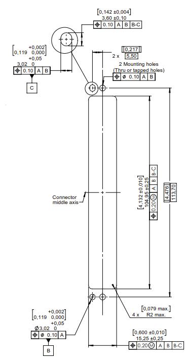
EPX SEr IES | 1-57 SIMPLIFICATION IS OUR INNOVATION Visit www.radiall.com for more information
Fixed
PLUG Floating Mount
Mount
Rack & Panel Application
EPXB4 SHELL DIMENSIONS & PANEL CUT-OUTS
RECEPTACLE
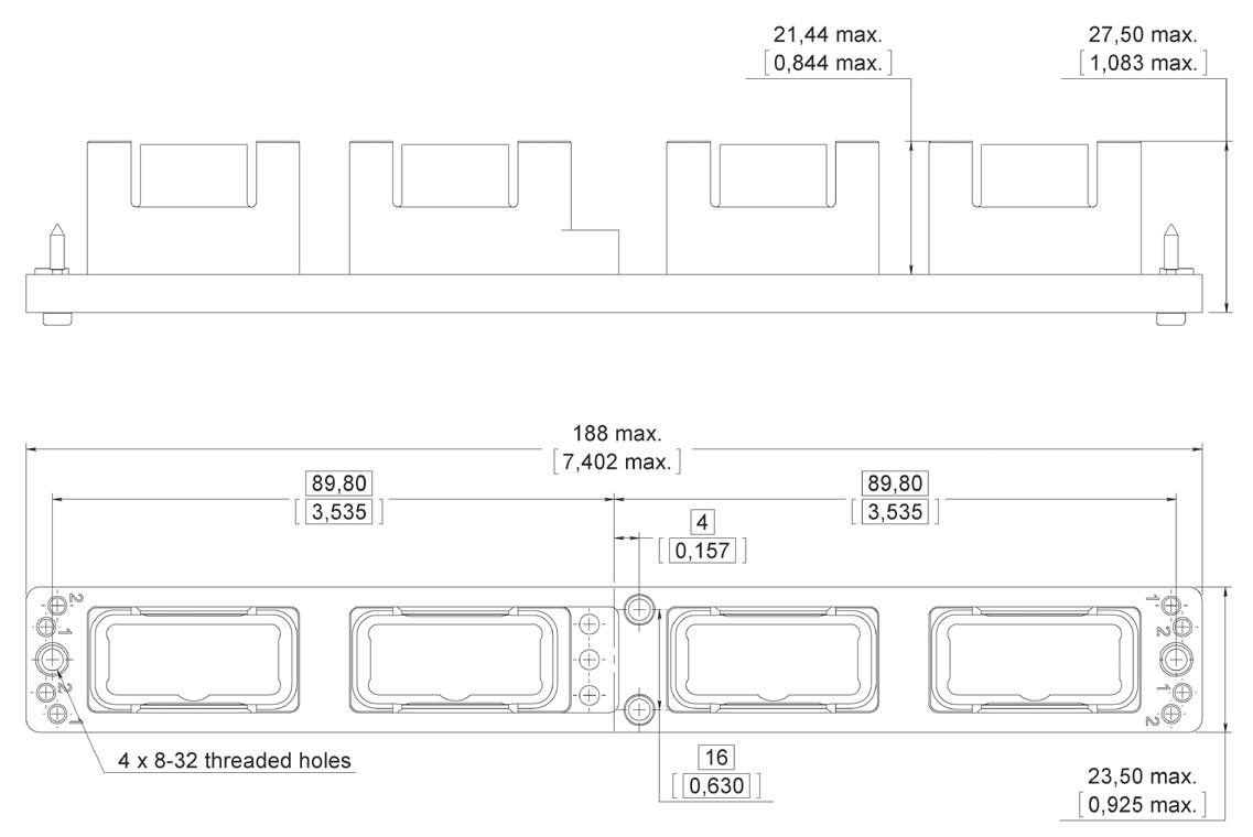
PANEL CUT-OUT
Receptacle - Shown from the Rear Side
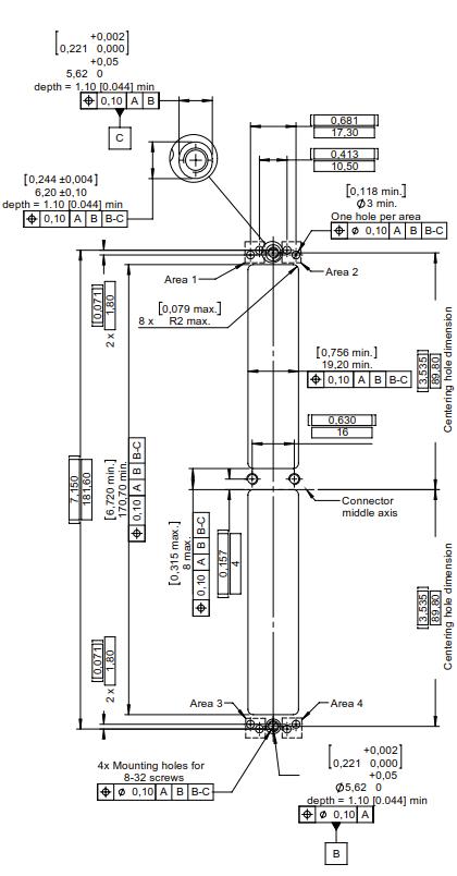
PLUG
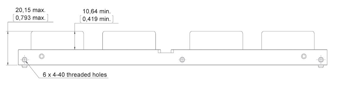
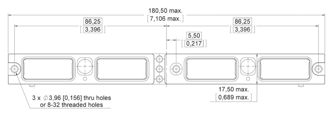
Plug - Shown from the Front Side
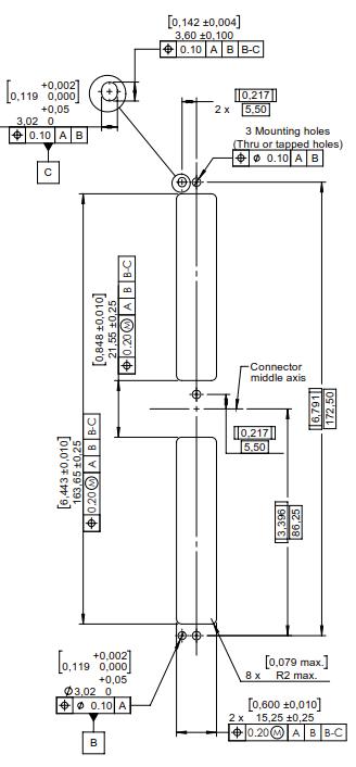
1-58 | EPX SEr IES SIMPLIFICATION IS OUR INNOVATION Visit www.radiall.com for more information
Rack
& Panel Application
RACK & PANEL ACCESSORIES
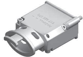
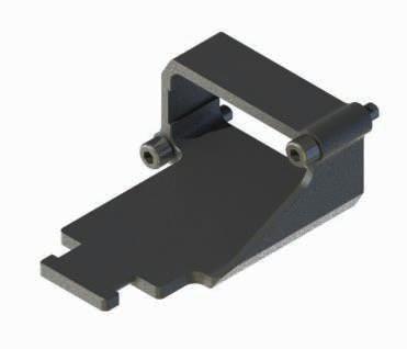
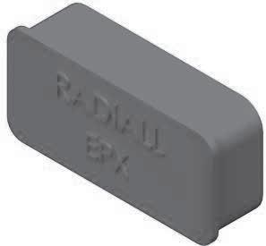
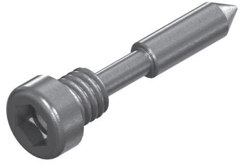
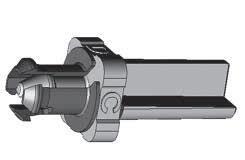
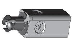
PART NUMBER
617925073
DESCRIPTION
EMI Backshell for Receptacle Only (Aluminium, Nickel-Plated)
617922022
617954002
617954003
617954004
617954005
Straight Strain Relief for Receptacle Only (Composite)
Dust Cap for Plug Shell (Pink Color)
Dust Cap for Receptacle Shell (Pink Color)
ESD Dust Cap Plug Shell (Black Color)
ESD Dust Cap Receptacle Shell (Black Color)
617980052 Coding Pin
617980030 Polarization Post
617980031 Polarization Key
EPX SEr IES | 1-59 SIMPLIFICATION IS OUR INNOVATION Visit www.radiall.com for more information
Rack & Panel Application
RACK & PANEL TOOLS
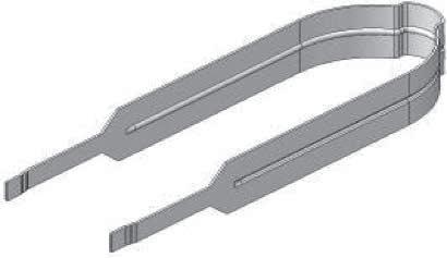
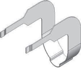
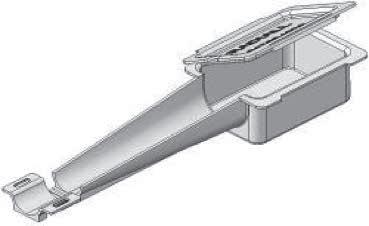
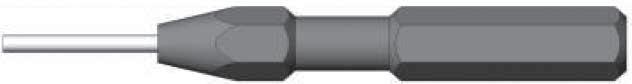
1-60 | EPX SEr IES SIMPLIFICATION IS OUR INNOVATION Visit www.radiall.com for more information
PART NUMBER DESCRIPTION
Insert Extraction
Right
282521002
Tool 282521004
Angle Insert Extraction Tool
617954020 Plastic Box to Protect Wired Inserts During Handling
F780855000
Hexagonal Hey 2 mm (5/64 in ) Flats for Sleeve Holder Removal
Rack & Panel Application
EPXB2 FOR LRU PRODUCT OVERVIEW
Detailed View of a Receptacle and Plug for the EPXB2 LRU Connector:
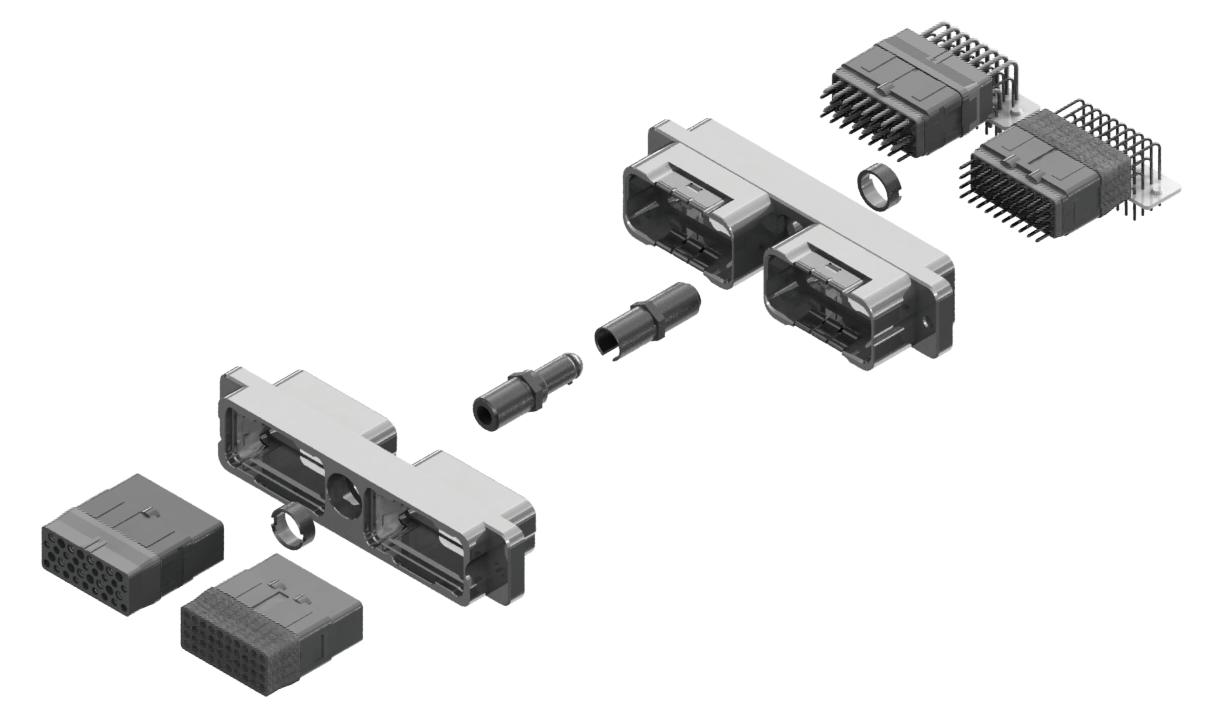
EPX SEr IES | 1-61 SIMPLIFICATION IS OUR INNOVATION Visit www.radiall.com for more information
Inserts
Pin Centering Guide
Plug Shell
Receptacle Shell
Socket Centering Guide
Rack & Panel Application
HOW TO ORDER EPXB2 SHELL FOR LRU
SERIES PREFIX
SHELL SIZE
B2: Two cavity shell
SHELL STYLE
For compatibility options, see the table below
L: Receptacle with flange
H: Classic receptacle
Z: Receptacle with ground block
R: Receptacle without ground fingers
P: Classic plug
W: Plug with ground block
D: iEPX plug with integrated stain-relief
SHELL MOUNTING
A: Panel rear mounted connector with 4 × 6-32 mounting holes
D: Connector with 2 × Ø 3 10 mm thru holes
F: Panel rear mounted connector with 2 × 6-32 mounting holes
L: Panel rear mounted connector with 2 × 4-40 mounting holes
LOCKING & POLARIZATION DEVICE [1]
4: Pin centering guide
5: Socket centering guide
POLARIZATION CODE
2: Polarizing device A to F delivered unassembled
3: Polarizing device N to Z delivered unassembled
SHELL PLATING
N: Nickel-plated aluminium
M: Nickel-plated composite
J: Nickel-plated, weight-optimized aluminium
AVAILABLE SHELL MOUNTING
N (Aluminium)
J (Weight-Optimized Aluminium)
M (Composite)
Notes
1. Pin/Socket centering guides can be mounted on either plug or receptacle shells. However, the standard options are: - Pin centering guide for plug shells - Socket centering guide for receptacle shells
1-62 | EPX SEr IES SIMPLIFICATION IS OUR INNOVATION Visit www.radiall.com for more information
EPX
SHELL STYLE A (4 × 6.32 UNC) B (No Holes) D (2 × Ø 3.10 mm) F (2 × 6.32 UNC) L (2 × 4.40 UNC)
L - - H - Z - -R - - -P - - W - - -
H - - - - P - - - -
L - - P - -
Class
Class
Class
Rack & Panel Application
HOW TO ORDER EPXB2 ASSEMBLY KIT FOR LRU
Assembly kits are delivered fully assembled including shell with inserts mounted, with or without contacts, according to the selection. When selecting your insert codes, do not forget to place them in the order you want them assembled. Locking and polarizing devices are delivered uninstalled.
Tips to help you in your selection:
• You are free to use either pin or socket inserts in EPXB plug or receptacle
• Crimp contacts can be delivered with a kit � Check which contacts will be included on page 1-10�
• PC tail contacts can also delivered with a kit � Remember that only straight pin PC tail contacts are available, and in receptacle only
• If PC tail contacts are selected, then all cavities including signal, power and quadrax are populated Size 5 coax cavities are not populated
All connector inserts will use the same insert class and the same contact termination.
SHELL SELECTION PA r T
SERIES PREFIX
SHELL SIZE
B2: Two cavity shell
SHELL STYLE
For option compatibility, see table on page 1-62
L: Receptacle with flange and ground fingers
H: Classic receptacle
Z: Receptacle with ground block
R: Receptacle without ground fingers
P: Classic plug
W: Plug with ground block
B: Bulkhead receptacle (bulkhead pin inserts compulsory)
SHELL MOUNTING
A: Rear panel mounted connector with 4 × 6-32 mounting holes
B: No mounting holes
D: Connector with 2 × Ø 3 �10 mm thru holes
F: Rear panel mounted connector with 2 × 6-32 mounting holes
L: Rear panel mounted connector with 2 × 4-40 mounting holes
POLARIZATION
1: Jackscrew polarizing device A to F
2: Jacknut polarizing device A to F
3: Without locking device
4: Pin centering guide for plug shell for LRU application only, polarizing device A to F
5: Socket centering guide for receptacle shell for LRU application only, polarizing device A to F
6: Jackscrew polarizing device N to Z
7: Jacknut polarizing device N to Z
SHELL PLATING
N: Nickel-plated aluminium
M: Nickel-plated composite
J: Nickel-plated, weight-optimized aluminium
INSEr T SELECTION PA r T
CONTACTS TERMINATION
XS: Socket insert without contacts
XP: Pin insert without contacts
SS: Socket insert with crimp contacts [1]
SP: Pin insert with crimp contacts [1]
YA: Gold PC tail contacts length A [2] [3]
ZA: Tin-lead PC tail contacts length A [2] [3]
RA: Pure tin (RoHS) PC tail contacts length A [2] [3]
INSERT CODE
Refer to page 1-10 to select insert code
INSERT CLASS
E: Environmental
N: Non-environmental
H: Non-environmental insert with a rear grommet, available for pin insert only (recommended for crimp contact)
T: Non-environmental insert with an interfacial seal, available for pin insert only (recommended for PC tail contact)
Notes
1. These contacts are delivered uninstalled. 2. Refer to pages 1-41 to select PC tail contacts for receptacle. 3. Not available with iEPX
EPX SEr IES | 1-63 SIMPLIFICATION IS OUR INNOVATION Visit www.radiall.com for more information
EPX
Rack & Panel Application
EPX GALLEY ARINC 810 PRODUCT OVERVIEW
The new EPXB2 Galley connector was specially designed for the severe conditions required by galley equipment � A floating mechanism was developed to avoid any risk of jamming and to guarantee a fully sealed connection.
The EPXB2 is used on ovens, beverage makers, refrigerators, microwave ovens and other equipment that fits within the new standardized galley layouts �
The EPXB2 connector is modular and provides extra contact density to add new contacts such as the #8 Twinax CAN data bus contact � Backshell accessories are also available�
Detailed view of receptacle and plug with accessories for the EPXB2 galley connector:
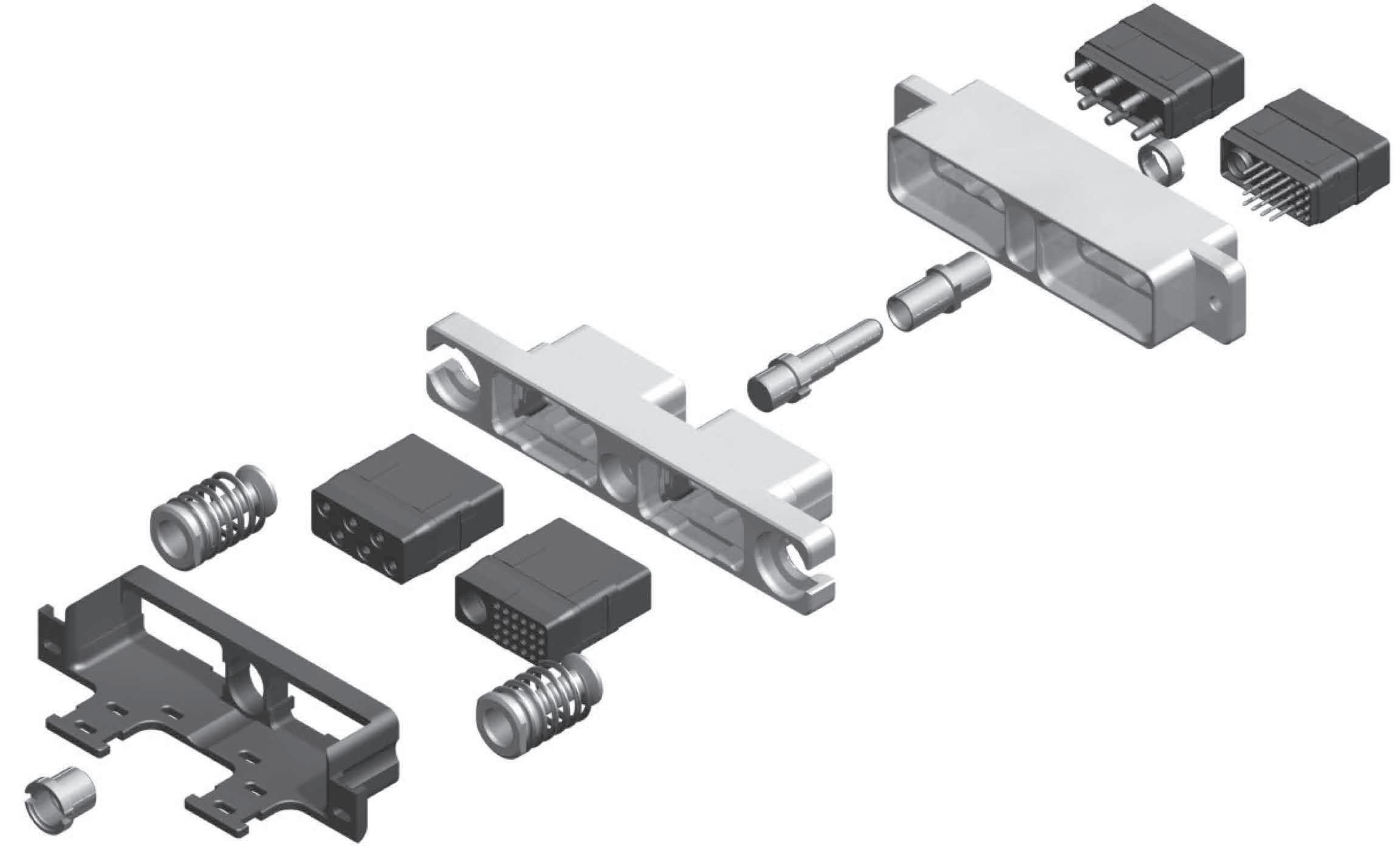
1-64 | EPX SEr IES SIMPLIFICATION IS OUR INNOVATION Visit www.radiall.com for more information
Springs & Fixing Axes
Plug Shell
Receptacle Shell
Guide Pin
Inserts with Contacts
Guide Bush
Screw
Rack & Panel Application
HOW TO ORDER EPX® GALLEY EQUIPMENT CONNECTOR
617610188 or 617610558
Each item included in the kit is indicated in the table below and can also be ordered separately�
r ECEPTACLE KITS
SHELL WITH 2 SELF-LOCKING THr EADED HOLES 617610188
r ECEPTACLE AND PLUG ASSEMBLY KIT PLUG KIT
617610189 contents
CAN DATA BUS CONTACTS
SHELL WITH 2 THrU HOLES
Notes
1. Part numbers
EPX SEr IES | 1-65 SIMPLIFICATION IS OUR INNOVATION Visit www.radiall.com for more information
PART NUMBER DESCRIPTION QUANTITY PER
617610212
EPXBE25Q1PA
for
EPXBE06PB Insert for
Pin Crimp Contacts/Size
15 617250 Pin Crimp Contacts/Size 12 6 616910 Filler Plug 9 617954003 Dust Cap 2
KIT
Receptacle Shell 1
Insert
Cavity A 1
Cavity B 1 617200
22
PART NUMBER DESCRIPTION QUANTITY PER KIT 617610419 Receptacle Shell
EPXBE25Q1PA
for
EPXBE06PB
for
617200
617250 Pin Crimp Contacts/Size
616910 Filler Plug 9 617954003 Dust Cap 2
617610558
1
Insert
Cavity A 1
Insert
Cavity B 1
Pin Crimp Contacts/Size 22 15
12 6
PART NUMBER DESCRIPTION
Receptacle Assembled Kit [1] 617610189 Plug Assembled Kit [1]
for assembly kits include: plug or receptacle shell, inserts, contacts, sealing plugs and dust caps.
PART NUMBER DESCRIPTION QUANTITY PER KIT 617610213 Plug Shell 1 EPXBE25Q1SA Insert for Cavity A 1 EPXBE06SB Insert for Cavity B 1 617300 Socket Crimp Contacts/Size 22 15 617350 Socket Crimp Contacts/Size 12 6 616910 Filler Plug 9 617922007 Strain Relief 1 617954002 Dust Cap 2
NUMBER DESCRIPTION
Size 8 Twinax
617065011 Size 8 Twinax
PART
617165011
Pin Contact
Socket Contact
Rack & Panel Application
DIMENSIONS & PANEL CUT-OUT
EPX® GALLEY EQUIPMENT CONNECTOr PEr A r INC 810
RECEPTACLE
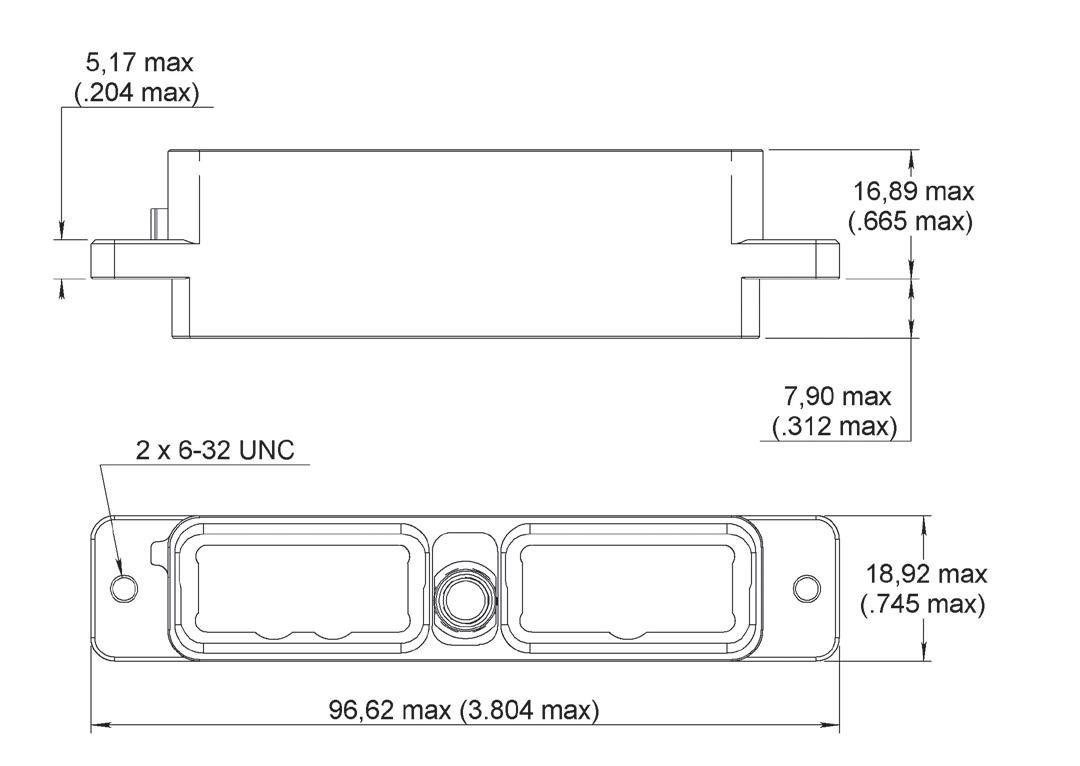
PANEL CUT-OUT
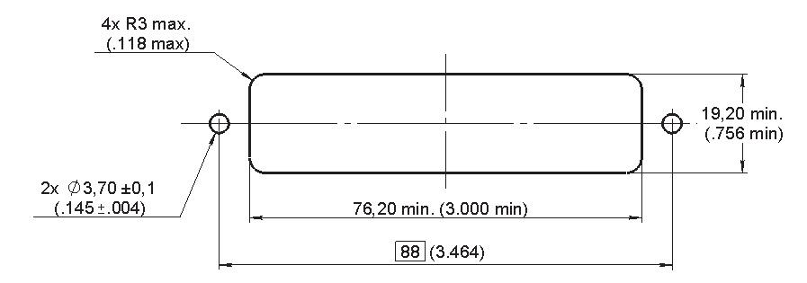
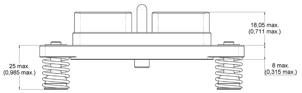
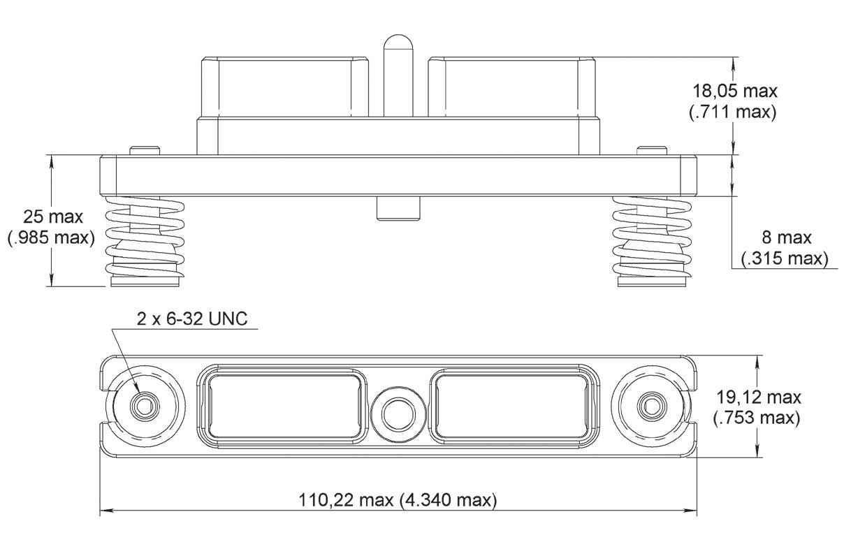
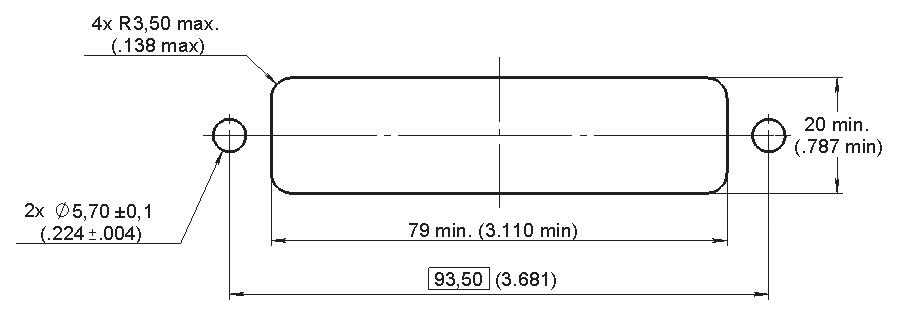
1-66 | EPX SEr IES SIMPLIFICATION IS OUR INNOVATION Visit www.radiall.com for more information
PLUG
Front Mount
Receptacle
Rear Mount
Plug
Rack & Panel Application
MULTI-GANG EPX® CONNECTORS
A whole range of multigang connectors are available for disconnect and Rack & Panel applications
Multigang connectors features and benefits:
• Weight-saving design
• Make installation easier and quicker
• Utilize EPX modularity and its whole range of inserts
• Take advantage of EPX connector functionalities and use EPXB2 standard plug shells with a multigang shell
SPECIFICATIONS
• Several cavities for EPXB inserts (4 to 20 cavities)
• Standard EPX strain reliefs and backshells available
• In accordance with EN4644 performances
Several options are available:
• Grounding block
• Grounding spring fingers
• Float mounting
• Spring-loaded mounting
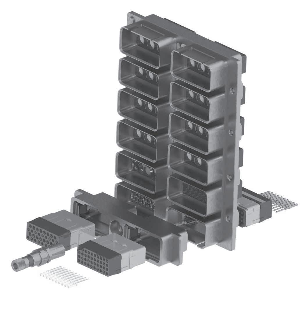
EPX SEr IES | 1-67 SIMPLIFICATION IS OUR INNOVATION Visit www.radiall.com for more information
1-68 | EPX SEr IES SIMPLIFICATION IS OUR INNOVATION Visit www.radiall.com for more information Notes