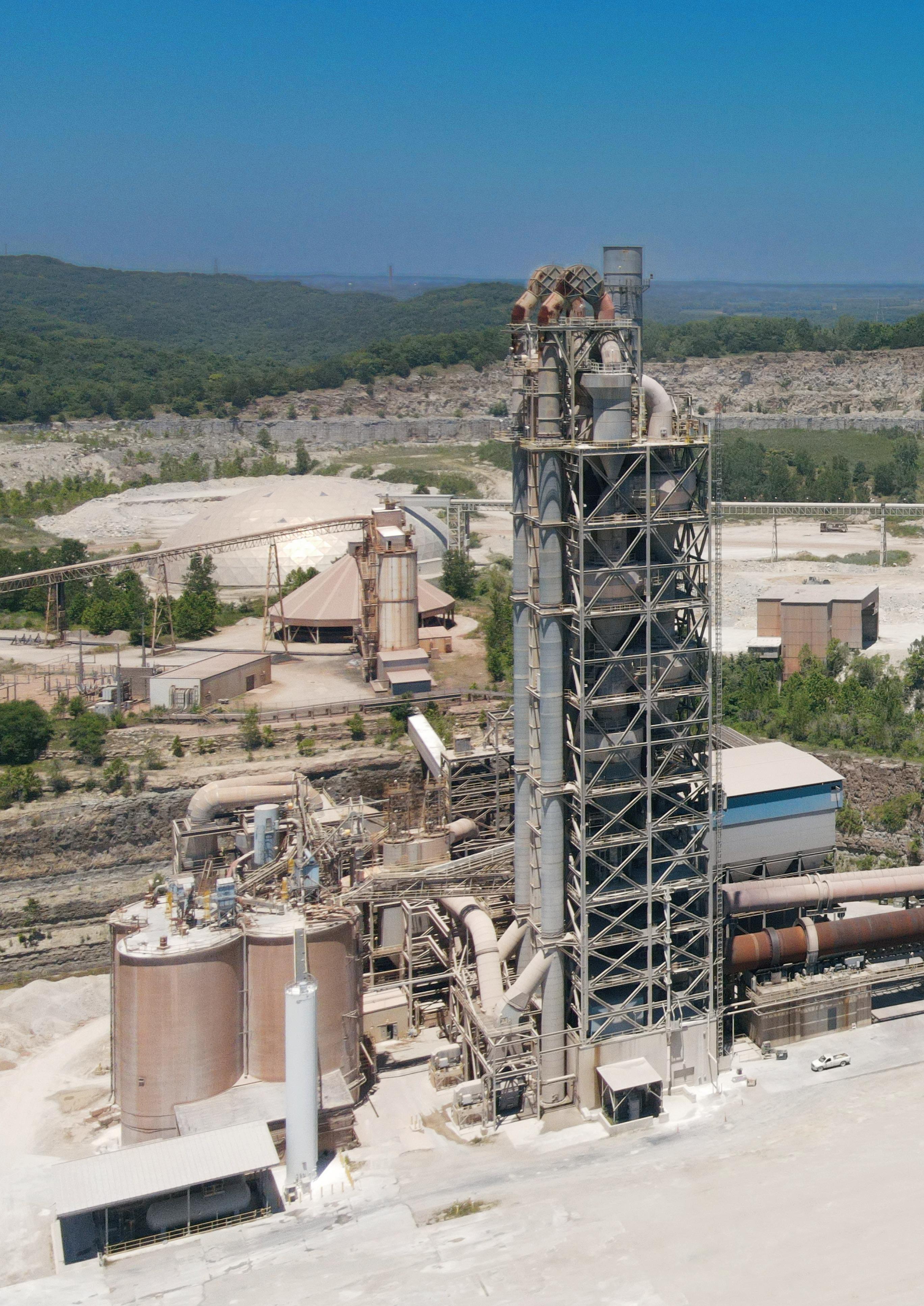
Buzzi Unicem’s Festus Plant with Loadout Powered by PSCL
Post-combustion technology that virtually eliminates CO2 emissions from cement manufacture.
• Captured CO2 is liquefied, purified and available for utilization in the cement manufacturing process, transportation, 3rd party sale or sequestration
• Removes 95 to 99% of carbon dioxide emissions
• Easy retrofit
• Suitable for existing and new plants
• Modular solution scales up to all plant capacities
• Less pre-treatment than alternative technologies
• Amine free
• Handles harmful contaminants, including NOx, SOx and mercury, more robustly than alternative technologies
Technology from:


03 Comment
05 News
REGIONAL REPORT
10 The Sub-Saharan Situation

David Bizley, Senior Editor of World Cement, provides a brief overview of the economic situation in Sub-Saharan Africa’s three largest economies: Nigeria, Ethiopia, and South Africa.
GRINDING & MILLING
14 The Role Of Retrofitting
Michael Lindbichler, CEMTEC, considers the benefits of retrofitting and how it can help cement plants be more sustainable.
PYROPROCESS OPTIMISATION
20 Blazing A Trail
Dr. Robert Pachler, Unitherm Cemcon, provides insight into the factors impacting burner design in the modern cement industry.
28 A Moment For Ammonia
M. Akritopoulos and T. Abbas, Cinar, and Syed Suhail Akhtar, Holcim, explore the advantages of burning green ammonia over hydrogen in a cement kiln.
35 Say ‘Bye’ To Carbon Dioxide
Joel Maia, FCT Combustion, explores the different pathways available for producers to reduce CO2 emissions from cement and clinker production.
CARBON CAPTURE
40 Hurdles To CCUS Adoption
Simon Thomsen, Leilac, explores the reasons for the cement industry’s hesitation to adopt CCUS technology, and explains how these challenges can be overcome.
45 Turning Emissions Into Solutions
Martin Keighley, CarbonFree, answers some of World Cement’s questions regarding carbon capture technology and its potential for application in the cement industry.
GREEN CEMENTS
50 A New ‘It Cement’
Hamed Maraghechi, CalPortland, discusses the development of ternary blended cements in California and considers their contribution to decarbonisation efforts.
56 Going Green
Grant Quasha, Eco Material Technologies, explores the benefits of a green alternative to Portland cement.
MATERIALS HANDLING & LOGISTICS
63 The Mobile App Advantage
Reiner Bachthaler, Axians Industrial Applications, explains how mobile applications can be highly beneficial in bulk goods industries.
69 Conveying Clinker GAMBAROTTA GSCHWENDT reviews different types of conveyors used to transport clinker for the cement production process.
AIR CANNONS & SILO CLEAN-OUT
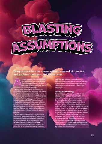
73 Blasting Assumptions
Dracyon considers the common weaknesses of air cannons, and explains how they can be overcome.
GEARS, DRIVES & MOTORS
77 Driving Sustainability with VFDs
Invertek Drives explains how variable frequency drives can help the cement industry to become more energy efficient.
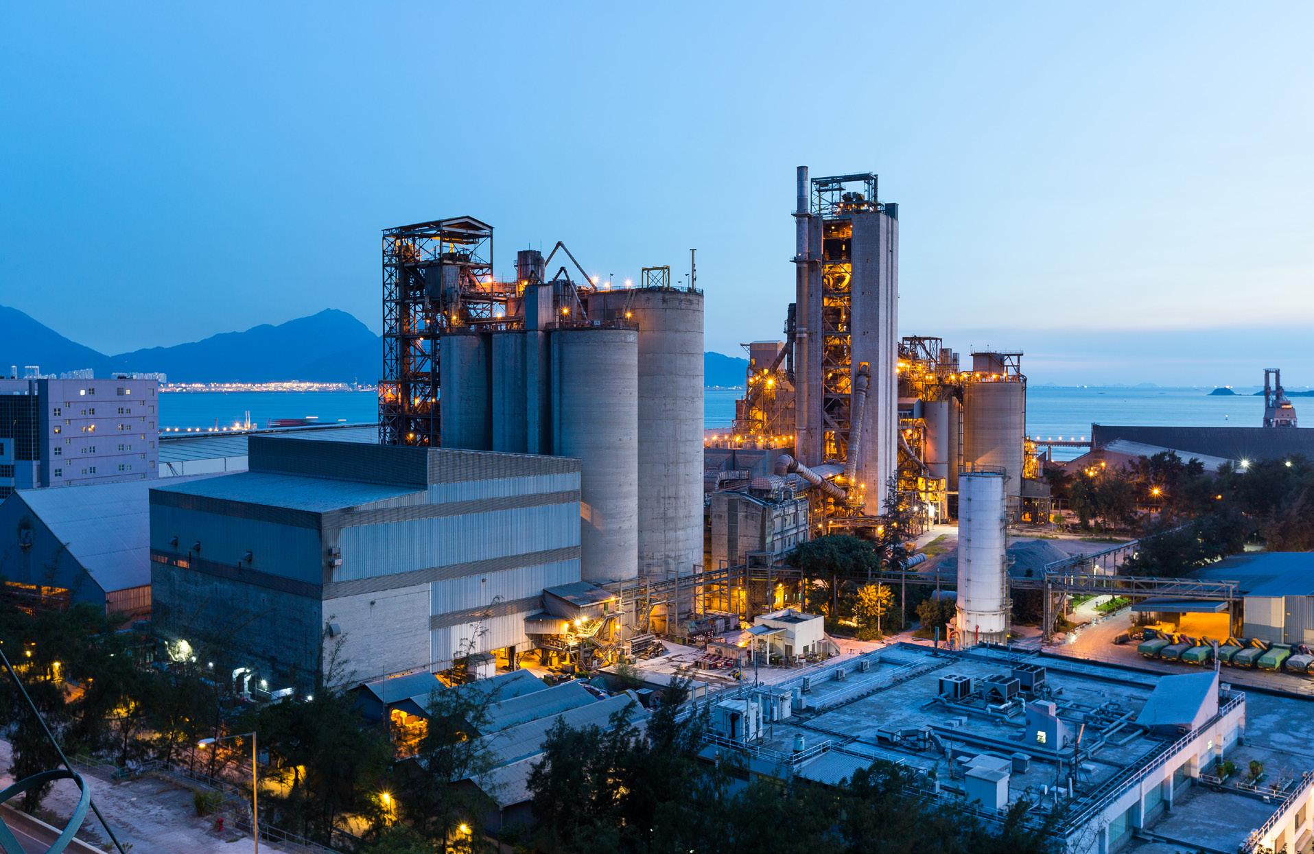
The Buzzi Unicem Festus Plant in Missouri benefits from comprehensive cement loading and quality solutions courtesy of PSCL. Through recent upgrades, PSCL’s Loading Management and Self-Service Loading solution now efficiently oversees all truck loading operations. Furthermore, PSCL handles all rail loading tasks. The plant uses the Raw Mix Control System by PSCL, guaranteeing top-notch product quality.


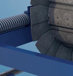


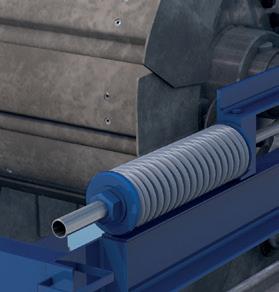
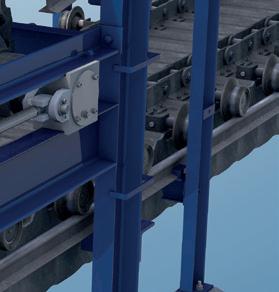

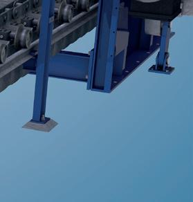


HEKO offers the whole range of chains, rollers, sprockets and scrapers for reclaimers. HEKO products are proven in thousands of bucket elevators and conveyors, worldwide.
Our components for the cement industry: central chains, link chains, reclaimer chains, sprockets, bucket elevators and clinker conveyors.
rod.hardy@palladianpublications.com
Sales Manager: Ian Lewis ian.lewis@palladianpublications.com
Sales Executive: Sophie Birss sophie.birss@palladianpublications.com
Head of Events: Louise Cameron louise.cameron@palladianpublications.com
Digital Events Coordinator: Merili Jurivete merili.jurivete@palladianpublications.com
Digital Administrator: Nicole Harman-Smith nicole.harman-smith@palladianpublications.com
Administration Manager: Laura White laura.white@palladianpublications.com
Reprints reprints@worldcement.com

Annual subscription (published monthly): £160 UK including postage/£175 (€245) overseas (postage airmail)/US$280 USA/Canada (postage airmail). Two year subscription (published monthly): £256 UK including postage/£280 (€392) overseas (postage airmail)/US$448 USA/Canada (postage airmail). Claims for non receipt of issues must be made within 4 months of publication of the issue or they will not be honoured without charge.
Applicable only to USA and Canada: WORLD CEMENT (ISSN No: 0263-6050, USPS No: 020-996) is published monthly by Palladian Publications, GBR and is distributed in the USA by Asendia USA, 17B S Middlesex Ave, Monroe NJ 08831.
Periodicals postage paid at Philadelphia, PA and additional mailing offices. POSTMASTER: send address changes to World Cement, 701C Ashland Ave, Folcroft PA 19032
Copyright © Palladian Publications Ltd 2024. All rights reserved. No part of this publication may be reproduced, stored in a retrieval system, or transmitted in any form or by any means, electronic, mechanical, photocopying, recording or otherwise, without the prior permission of the copyright owner. All views expressed in this journal are those of the respective contributors and are not necessarily the opinions of the publisher, neither do the publishers endorse any of the claims made in the articles or the advertisements. Uncaptioned images courtesy of Adobe Stock. Printed in the UK.
Palladian Publications Ltd 15 South Street, Farnham, Surrey GU9 7QU, UK
Tel +44 (0)1252 718999
Email: mail@worldcement.com Website: www.worldcement.com
DAVID BIZLEY, SENIOR EDITOR
ast month you may recall that I talked about how 2024 was the year of elections, with more than half the world due to visit the polling booth at some point this year. However, another thing that 2024 is likely to be remembered for is being the year that the use of ‘AI’ across business and industry really took off.
You might be wondering about the inverted commas around AI in the previous sentence. Well, allow me to derail the flow of this Comment briefly and explain that that’s because what we’ve come to know as AI isn’t really AI in the true meaning of the name. It’s certainly artificial , but there’s no actual intelligencethere. Tools like ChatGPT, whilst impressive and undeniably useful, remain incapable of actual comprehension, thought, or invention. They’re pattern finding algorithms feeding off data from the internet and reacting to user input, unlike the ‘true’ AI behind fictional entities like C3P0, HAL 9000, or even Skynet, which have their own sense of self.
OK, enough pedantry for now; back to the point – whilst what we know today as AI might not be about to start spouting ‘Cogito, ergo sum’ or develop a sense of existential dread (probably for the best, honestly), it still has huge potential for use across industry, being able to analyse thousands of data points at speeds far beyond human ability. And as much as we might laugh at ChatGPT’s gaffes or habit of ‘hallucinating’ answers, the big players across industry, including cement, are making serious investments into the technology.
Holcim, for example, has announced plans to scale up its use of AI across more than 100 of its plants around the world over the next four years. With AI already deployed at 45 plants to predict and prevent failures before they occur, the company plans to deepen and broaden this application to boost operational resilience. This will involve the further rolling out of a predictive maintenance solution from AI platform software provider C3 AI, as well as piloting generative AI to enhance its capabilities.
Holcim’s CEO, Miljan Gutovic, stated: “AI is a transformative technology that will revolutionise our industry. Already widely embedded across Holcim, AI catalyses operational efficiency and enhances customer service. We will ultimately scale up our use of AI to hundreds of sites worldwide.”
Cemex has also announced its use of a generative AI system to “transform how the salesforce interacts with clients by providing real-time support for a superior customer experience.” The development process involved training a Microsoft AI on Cemex’s product information and expertise in construction regulations. Cemex CEO, Fernando A. González, was equally enthusiastic about the role of AI: “Digital transformation is a top priority at Cemex, as we are continually looking for new digital solutions to innovate and drive more efficient, sustainable, and safer construction projects for our customers.”
Now, if you’d like to hear more about how AI and other cutting-edge technologies are shaping the cement industry, then you’ll be pleased to know that WorldCement’sflagship virtual conference, Optimisation, is coming back for a fifth iteration on 22 October! Featuring Keynote Presentation from Molins’ Chief Technology Officer, Javier Sueiras, this is a fantastic opportunity to learn about the future of cement production. Register today, free of charge: www.worldcement.com/events/optimisation-2024
Convey units
Truck loading
GCCA
UNIDO supports its 172 Member States with economic and industrial development, in line with the UN’s Sustainable Development Goals (SDGs). With its long-standing experience in renewable energy projects and the application of clean energy technologies in industry, UNIDO collaborates with a wide range of partners globally supporting industries on their pathway to net-zero emissions.
The GCCA is the cement and concrete industry’s main membership body, representing 80% of cement production outside of China, as well as a number of leading Chinese manufacturers.
The two organisations have agreed a Memorandum of Understanding (MoU), which will see them working together on key sustainability and decarbonisation issues.
Speaking at the signing ceremony in Austria, Gerd Müller, Director General of UNIDO, said: “Cement and concrete are a vital part of resilient infrastructure development. Decarbonising the cement and concrete sectors worldwide is essential to reducing CO2 emissions and tackling climate change. The GCCA and its members are leading the way on doing so for this important global industry. Our UNIDO Member States face a number of technical, market-related and policy hurdles that make decarbonisation commitments even more challenging. That is why I am very glad to sign this Memorandum of Understanding with the GCCA and start a new phase of closer cooperation that will help our Member States overcome those challenges.”
Thomas Guillot, GCCA CEO, said:
“Through our Net Zero Roadmap and the accelerator programme we have put in place, we are already working with policymakers, governments and industry to overcome procurement and resourcing challenges across the global south. Having this ground-breaking agreement with UNIDO is a natural progression which we hope will fast-track progress in a meaningful way.”
The partnership agreement includes pledges to: f Provide recommendations for decision-makers to create the right market environments for the development of low and near-zero emissions cement and concrete.
f Develop innovative technological solutions to help meet net-zero commitments.
f Organise joint international industry and government events.
f Jointly author and publish documents, recommendations and research tools.
f Identify promising companies and innovative solutions and showcase these at relevant events and in publications.
Vattenfall and Cemvision cooperate to supply near-zero emission cement
Vattenfall and Cemvision have entered an agreement (LOI) for the development and future supply of near-zero emission cement.
The new cement has the potential to reduce carbon dioxide emissions by 95% compared to traditional cement.
It has several potential applications, such as foundations for wind power turbines, power distribution and prefabricated concrete elements. Both Vattenfall and its subcontractors could become important new customers for this new product.
Cemvision develops cement made from recycled residual materials from industries including mining and steel industries manufacturing in a process where Cemvision’s kilns are fuelled by fossil-free energy. Compared to traditional cement production, which emits large amounts of carbon dioxide due to the use of virgin limestone and fossil fuels, Cemvision can reduce the carbon footprint by up to 95%.
“We are delighted to deepen our partnership with Vattenfall and to welcome them to our growing customer base. Already today in our demo production, we are reducing carbon emissions by 80%, and as we optimise processes and supply chain, we will reduce by up to 95% by 2030. Near-zero emission cement is the most efficient way to achieve significant climate benefits without increasing the overall cost of a construction project. It does not have to be difficult to change, but it is important to start in time and help accelerating the transition”, says Oscar Hållén, CEO of Cemvision.
“Vattenfall is very positive about participating in the development of a market for near-zero emission cement by creating demand as a customer. We can also contribute with product verification at our concrete laboratory. The global impact of cement
production makes it necessary to find a way forward with as low carbon emissions as possible, the climate and the future of construction demand it. This is an innovative solution with great potential”, says Annika Ramsköld, Head of Sustainability, Vattenfall.
Cartagena, Colombia www.ficem.org
SOLIDS Dortmund 2024
09 – 10 October, 2024 Dortmund, Germany www.solids-dortmund.de

Virtual Conference: 22 October www.worldcement.com/events/ optimisation-2024
17th TÜRKÇIMENTO Technical Seminar & Exhibition
02 – 05 November, 2024 Antalya, Türkiye teknikseminer.com.tr
AFCM Technical Symposium & Exhibition Malaysia 2024 04 – 07 November, 2024 Kuala Lumpur, Malaysia 26afcm-tse.com
VDZ CONGRESS
06 – 08 November, 2024 Düsseldorf, Germany www.vdz-online.de
AUCBM AICCE27 26 – 28 November, 2024 Tunis, Tunisia www.aucbm.net

09 – 12 March, 2025 Athens, Greece worldcement.com/envirotech2025
As a member and founder of the First Movers Coalition (FMC), Vattenfall has pledged that at least 10% of its cement or concrete purchases will be as close to zero emissions as possible by 2030. The FMC’s overall goal is to take climate action by creating a market for emerging technologies that are crucial to reaching near-zero emissions by 2050.
Heidelberg Materials converts cement plant to a slag grinding facility in Indiana
Heidelberg Materials has announced the successful conversion of its cement plant in Speed, Indiana, USA, to a slag grinding facility to better support the increased demand for sustainable products in the fast-growing Midwest market.
Following last year’s opening of its new state-of-the-art cement plant in Mitchell, Indiana, Heidelberg Materials ceased Portland cement production at its manufacturing site in Speed, Indiana, and invested in modifying the facility to produce slag cement from domestically sourced slag granules. Replacing a portion of conventional Portland cement with slag cement in a concrete mix significantly lowers its environmental impact. The Speed site, which has an annual grinding capacity of more than 400 000 t, also serves as a distribution hub for cement produced at the Mitchell plant as well as a broad range of specialty cementitious products.
The adjustments made at the Speed plant reflect Heidelberg Materials’ strong commitment to achieving net-zero emissions in North America. Recently, the company has been selected for funding of up to US$500 million by the US Department of Energy to advance industrial-scale carbon capture, transport, and storage at its Mitchell cement plant. At the Edmonton cement plant in Alberta, Canada, Heidelberg Materials is currently developing the world’s first full-scale carbon capture, utilisation, and storage solution in the cement industry.
Advancing urbanisation is driving infrastructure demands for residential and industrial space, also spurring increased demand for cement. For cement producers, flexibility and, above all, proximity to the market and speed in logistics are the keys to success and profitability.
In response, HAVER & BOECKER developed the OCTAPLANT®, a new packing concept. The OCTAPLANT, a comparatively compact system for packing and loading cement in bags, consists of a modular design incorporating high quality technology and prefabricated components to allow for quick installation and adaptability.
Significant time saving is the main advantage that OCTAPLANT offers in comparison to conventional systems. With all components on the shelf and many of the assembly tasks completed before the


system ships, the construction phase of the plant is significantly reduced. Less construction needed on site translates to fewer potential errors and reduced labour demands for installation. It also comes into play at the very start of the planning phase. Engineering that is completely planned and finalised down to the last detail accelerates project implementation and ensures the best possible planning security with regard to expected costs, yields, equipping buildings and technology. Moreover, standard delivery of all the tools required for assembly avoids expensive delays that could occur due to missing or incompatible devices and systems. The simple, modular design decreases the need for crane lifts to erect the plant by 80% over the installation of conventional systems. A plug-and-play design, allows for individual elements to simply connect and be operational quickly reducing overall installation time and facilitating quick relocation of the plant based on business potential or demand. The installation time from planning to the start of production is reduced by three and a half months compared to conventional systems, allowing for lower finance costs and a rapid return on investment.
An OCTAPLANT building consists of three segments. The heart is the eponymous octagonal ‘OctaTower’ that houses the HAVER & BOECKER ROTO-PACKER® RVTs packing system, including a foreign body screen, pre-hopper and spillage return system.
These elements are shipped in a simplified and cost-optimised manner in seven standard sea containers, from which the adjacent container building is erected after unloading. It provides space for the bag discharge line, the fully automatic
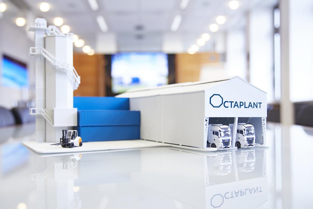
RADIMAT® bag applicator, the system control and the compressor unit. The final section is a lightweight hall where the filled cement bags are loaded onto trucks. The HB 10 system for rear loading and the HB 17 system for loading open trucks are available here. Moreover, a photovoltaic system can be installed on the roof and thus generate sustainable electricity for the plant.
The OCTAPLANT’s efficient design is adapted to the extreme site conditions of the target markets. The containers are reinforced and reliably withstand wind speeds of up to 200 km/h and earthquake loads. The light-colored façade is designed to reflect solar radiation. In addition, the air flow from the packing machine’s dust extraction system not only creates a low-dust environment, but also provides measurable temperature regulation. The OctaTower and container building can also be sufficiently insulated for colder climates.
Thanks to its mobility and space-saving design, the OCTAPLANT saves on resources and materials. Existing system components and high-quality technical equipment can be easily reused at another location.
Space-optimised transport and a high degree of prefabrication also contribute to a reduced ecological footprint. Finally, the integration of QUAT2RO® products and the PROcheck life cycle approach minimise greenhouse gas emissions, energy consumption and the use of materials during plant operation.
In order to control, monitor and optimise all processes, all the workflows are networked using QUAT2RO System Intelligence. With the PROcheck life cycle approach, HAVER & BOECKER enables comprehensive support: from selecting the right equipment with the right empty bags to offering spare parts and comprehensive services.
When developing the space-optimised and relocatable system, the focus was on ease of operation and maintenance. The OCTAPLANT offers maximum efficiency not only in terms of planning and building design, but customers can also count on maximum output and high quality from the packing machines when it comes to technical equipment and efficient operation.
The engineering for the OCTAPLANT concept was completed by HAVER & BOECKER so that project planning and production could take place immediately. Significant time saving is the main advantage that


David Bizley, Senior Editor of World Cement, provides a brief overview of the economic situation in Sub-Saharan Africa’s three largest economies: Nigeria, Ethiopia, and South Africa.
Sub-Saharan Africa is a vast region, comprising the majority of the continent’s 50+ nations and their 1.2 billion citizens, and is spread across 43.3 million km2 (or 15% of the Earth’s land surface). As such, a full review of the region falls well beyond the scope of this article, which will instead limit itself to a brief discussion of the three major economies: Nigeria, Ethiopia, and South Africa.
Nigeria’s economy has undergone a turbulent period as of late – and that might be putting it mildly, with the BBC referring to the disruption earlier this year as the “worst economic crisis in a generation, leading to widespread hardship and anger.” The economic malaise has even seen the country fall to fourth place, down from first in the IMF’s ranking of the largest economies in Africa.
Like many nations around the world, Nigeria has struggled with inflation over recent years, but the problem had become particularly acute by the beginning of 2024. To list just a few figures: annual inflation rose to 30%, food prices have risen by 35%, and the monthly minimum wage of 30 000 naira has not risen since 2019 and is now worth just US$19. So, what has caused this crisis? In addition to the same external factors being felt by much of the rest of the world, the war in Ukraine for example, Nigeria’s President Tinubu has inherited something of a tricky situation from his predecessor. Former President, Muhammadu Buhari, had taken out loans worth US$19 billion from Nigeria’s central bank to cover government spending – the bank duly obliged and printed the money, thus further exacerbating inflation.
Tinubu’s own policies, however, must take some of the blame for the situation as his attempts to reshape the Nigerian economy for the better have had some unintended consequences. One of his first acts upon being sworn in was to end a long-standing fuel subsidy, which had kept prices low for many citizens. Whilst the subsidy was hugely expensive, and it was (quite reasonably) argued that the money would be better spent on healthcare and education, the sudden rise in fuel prices sent shockwaves down the supply chain with increased transportation costs for goods ultimately being passed on to the end consumer.
Tinubu also brought an end to the policy of pegging the naira to the US dollar. Again, this seemed like a reasonable move because maintaining the dollar peg had been exorbitantly expensive for the central bank. However, once the peg was removed, the value of the naira tumbled by more than two-thirds, briefly reaching all-time lows back in February. In May of 2023, 10 000 naira was worth US$22 – at the time of writing, it is only worth US$6.49.
It’s not all gloom, however. The IMF, which is broadly in favour of Tinubu’s economic reforms and sees the current disruption as a short-term pain needed for long-term gain, expects GDP growth of 3.2% for 2024, and welcomes recent improvements in revenue collection and oil production, a targeted safety net programme of cash transfers to vulnerable households, and a tightening of monetary policy.
In terms of cement demand, IA Cement predicts a ‘relatively normal’ recovery of 3 – 4% in 2024. A possible price war between competing producers, which had been ramping up in 2023 and could have boosted demand this year, appears to have been ruled out by the falling value of the naira. Indeed, prices have actually soared, with the average price for a bag of cement rising from ~4000 naira to a peak of 11 000 – 15 000 naira in May, before falling back to lower, but still high, prices around 7000 – 8000 naira at the time of writing.
Investments are also still being made in the cement sector. In May of this year, Finnish manufacturing group, Wärstilä, signed a 10 year operations & maintenance (O&M) agreement for a captive power plant providing the energy to a new cement plant in Kogi State, owned by Mangal Industries.
The power plant is critical to the facility’s cement production since the site is remotely located with only limited access to the electricity grid. It operates with five Wärtsilä 34DF dual-fuel engines delivering an output of 50 MW. The O&M agreement is designed to ensure that the facility can reliably maintain its cement production target of 3 million tpy.
Ethopia, after Nigeria, is the African continent’s second-most populous nation with a population of 126.5 million. Despite having one of the fastest


growing economies in the region (recording GDP growth of 7.2% in 22/23), it also remains one of the poorest, with per capita gross income of just US$1020.
The World Bank reports that the country’s “consistently high economic growth over the last decade resulted in positive trends in poverty reduction in both urban and rural areas. The share of the population living below the national poverty line decreased from 30% in 2011 to 24% in 2016 and human development indicators improved as well.” The country aims to reach lower middle-income status by 2025.
To maintain this growth, the government has implemented a 10-year development plan, which aims to further work from previous similar plans and promote the shift towards greater involvement of the private sector in the economy.
Recent years have been marred by high levels of insecurity, primarily as a result of the so-called Tigray war, which formally ended in November 2022. Each side (the Ethiopian military and the Tigrayan regional forces) has accused the other of crimes against humanity, including arbitrary detentions and even massacres – a UN report in late 2023 found that there was strong evidence that, even despite the truce, war crimes and crimes against humanity continued to be carried out. The Economist Intelligence Unit reports that while the peace remains fragile, with active insurgencies in the Amhara and Oromia regions, the relative improvement in the security situation will drive a gradual increase in GDP growth.
In terms of cement, at the time of writing, the country is on the verge of welcoming a brand new cement plant in the Amhara region, some 130 km north of Addis Ababa. At a cost of US$2.2 billion, the Lemi National Cement Factory is expected to make significant inroads into addressing building materials shortages in the country by almost doubling national production with its output of 4.5 million tpy. Lemi National Cement PLC currently is a member of the joint venture formed between East African Holding and West International Holding (WIH), a Chinese industrial enterprise.
In other local cement news, the Ethiopian Cement Association has been working with local producers to gradually move away from imported coal supplies, which cost businesses US$300 million a year. Despite having 600 million t of domestic coal reserves, local supply has been oversaturated with low-quality coal from small-scale producers. The few industrial-scale producers have failed to reach demand, ever since exploration was opened up in the 1940s.
Low quality coal has been recognised as a key factor behind the country’s lacklustre cement production and the move towards domestic supplies would be gradual and contingent on the improvement of the quality and availability. Adugna Bekele, president of the Ethiopian Cement Association, noted that “quality would be the deciding factor” in bringing the cement producers on board and emphasised the
importance of adopting coal-washing technologies and establishing industrial-scale processing systems.
News regarding South Africa’s economy has been, to quote the FinancialTimes, “unceasingly negative for years, with power outages, chronic unemployment, state corruption, crime, pitiful economic growth and a downward-trending rand as a constant background.” The World Bank broadly agrees and begins its overview of the country by highlighting that the country’s growth has been hampered for years by electricity supply shortages, with rolling scheduled power cuts (known as ‘load shedding’) starting as far back as 2007, and only intensifying since 2022. The total accumulated duration of the outages (each of which lasts 2 – 4 hours), amounted to a staggering 289 days in 2023, increasing from 157 days in 2022 and 48 days in 2021.
The country has made considerable advances in improving the lives of its citizens since the switch to democracy in the mid-1990s, but progress has stagnated for the last decade. According to the World Bank, the percentage of the population living below the upper-middle-income poverty line between 2005 and 2010 fell from 68% to 56%, but the trend has since reversed with the figure rising to 57% in 2015 and could even be as high as 62.7% for 2023.
Some good news may lie ahead, however. The regular power outages, which have served as a considerable obstacle to business could be due to diminish and ultimately stop within the next couple of years. In 2022, President Cyril Ramaphosa removed limits on how much private generators could produce, which should see some 10 GW of cheap, renewable energy enter the market. The beleaguered state transport & logistics enterprise, Eskom, which oversees rail and ports, is under new management and engaging with private businesses to boost productivity after a year when domestic supply chain issues caused coal exports (as just one example) to fall to 50 million t, their lowest level since 1993. So, whilst challenges remain, the tide may be about to turn for the better.
There is also some positive news from the South African cement sector as the country’s largest producer, PPC, was able to pay its first dividend to investors in nine years. Whilst most of the 20.6% revenue growth came from the company’s Zimbabwe operations, revenues from the South African and Botswanan operations still grew by 5.2%. The company is currently going through the process of divesting its ‘rest of Africa’ assets, having just sold its 51% stake in the Rwandan CIMERWA for US$42.5 million. On the back of the positive results, CEO Matias Cardarelli has struck a note of cautious optimism by stating that the company’s “sustained underperformance and decreasing profitability over a number of years [had] revealed internal gaps that are also clear opportunities.”

N+P’s Subcoal ® portfolio is specifically designed to increase alternative fuel substitution rates up to 100%. This can be done using existing (coal) feed and burner systems. Our alternative fuels are manufactured to high demanding specifications so that it is easy to handle, transport and process, whether co-fired with coal or as a 100% fuel substitute.
All you need to know about reducing CO 2 emissions with alternative fuels: www.npgroup.com


Michael Lindbichler, CEMTEC, considers the benefits of retrofitting and how it can help cement plants be more sustainable.
In the cement industry, the focus on decarbonisation is paramount, but it is not the only concern driving daily operations. Closely related to decarbonisation is the concept of sustainability, particularly through retrofitting. Many cement plants worldwide have been operational for decades. As requirements for product fineness and quality evolve – driven by the increasing substitution of clinker – older systems often reach or exceed their operational limits, necessitating optimisation or upgrades. Additionally, wear material fatigue and the end of the useful lifetime of individual machines or entire plants demand predictive and preventive actions to maintain competitiveness and ensure a secure supply chain.
Addressing these requirements can involve significant investments in new processing lines

or, alternatively, the replacement of single items or assembly groups of affected equipment. From a sustainability perspective, the logical solution in many cases is to retrofit plants to state-of-the-art technology, thereby optimising capital expenses (CAPEX), reducing operational costs (OPEX), and achieving the lowest total cost of ownership (TCO). Retrofitting can extend the operational life of existing plants, improve energy efficiency, and reduce emissions, aligning with global environmental goals. This approach not only supports the environment but also ensures that cement plants remain competitive and economically viable in an increasingly challenging market.
Retrofitting involves adapting existing equipment or plants to meet current requirements. This can range from upgrading small components to replacing complete assembly groups and, in some cases, may involve exchanging all plant equipment constrained only by existing foundations or building dimensions. These extensive projects often necessitate customised solutions derived through reverse engineering. Reverse engineering in combination with retrofitting not only replaces insufficient or broken items but also allows for the incorporation of improvements in rigidity, performance, and safety. Safety has become increasingly crucial in every plant, often serving as the impetus for retrofit projects. Enhanced safety
features can reduce the risk of accidents and ensure compliance with the latest regulatory standards, which are constantly evolving to address new challenges and risks.
A significant challenge in executing retrofit projects is the frequent lack of information, such as incomplete documentation or missing drawings. This can stem from various reasons, including never having received proper documentation, loss of documents, or invalidation due to numerous on-site modifications. However, the engineering phase of retrofitting offers the opportunity to include internals, wear and spare parts, simplifying future maintenance. The ability to reverse-engineer components and systems plays a critical role in overcoming these challenges, enabling the creation of accurate and reliable designs based on existing conditions.
In the past, collecting missing information and dimensions was laborious and time-consuming. Today, technologies like 3D laser scanning facilitate this process. Scans can be easily converted into 3D model files compatible with most CAD systems, providing a solid foundation for new engineering. Scanning entire buildings, including installed equipment, steel structures, and foundations, can be accomplished in just a few days, depending on the required accuracy. This innovation significantly reduces the time and cost associated with the initial assessment and planning stages of retrofit projects. The accuracy of 3D scanning ensures that retrofits are precisely tailored to existing structures, minimising the risk of errors and costly modifications during implementation. Moreover, 3D scanning can be used for regular monitoring and maintenance checks, helping to identify wear and tear before they become critical issues.
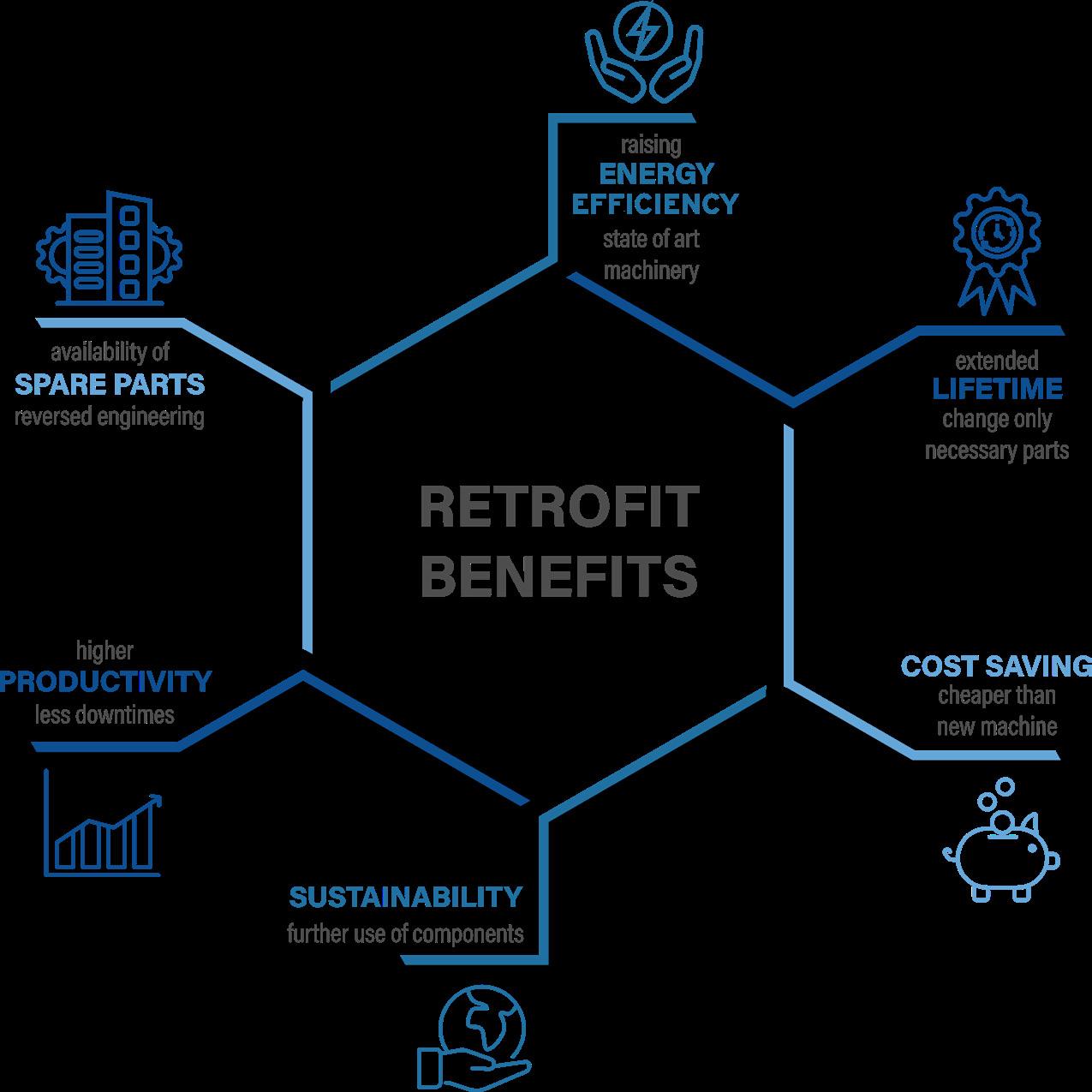
Older machines often lack sufficient condition monitoring or interlocking systems that help extend the lifespan of critical parts such as drives, bearings, and other sensitive components. The cost of investing in such monitoring systems is relatively low when considering the reduced maintenance and Retrofit benefits.
repair costs. Incorporating systems like vibration or temperature monitoring in retrofit projects
ensuring that every minute is effectively utilised to enhance plant performance.

Proper lubrication is essential to minimize wear and lengthen equipment life in high-temperature, high-load applications

Easy Bar® with Almasol® is a patented blend of wear-reducing and extreme pressure lubricants suspended in a solid binder that melts after application. It prevents steel-on-steel contact, without risk of flameups, and takes less time to apply than traditional lubricants.
For more about LE’s high-performance lubricants, contact us or visit our website today.
In addition, the integration of renewable energy sources, such as solar or wind power, into the plant’s energy mix can further reduce carbon footprints and operational costs.
The advantages of retrofitting are not limited to cement plants but extend to other mineral processing plants and mining companies. Effective project planning often requires multiple discussions between customers and potential suppliers to fully understand the requirements. The goal is to collaboratively find and offer the best solutions in terms of functionality, quality, and budget. Success begins with professional consulting requiring years of experience and expertise in various disciplines such as mechanical engineering, electrical and automation engineering, and plant and process engineering. Considering the entire grinding plant with all its interrelations is crucial. Detailed analysis of the interrelations between different plant components can lead to more comprehensive and effective retrofit solutions. This holistic approach ensures that all aspects of the plant are optimised, resulting in more cohesive and efficient operations.
Flexibility is essential for suppliers as most projects demand customised solutions rather than standard equipment deliveries. This flexibility extends from organisational style and decision-making processes to the ability to bypass internal procedures throughout the supply chain, from engineering to commissioning and beyond. Tailored solutions can address specific operational challenges and align with the unique goals of each plant, ensuring maximum benefit from retrofit projects. Suppliers must be agile and responsive, able to adapt to changing project requirements and deliver solutions that meet the precise needs of their clients.
Given the rarity of new plant projects or new grinding terminals for cement in Europe and the USA, the retrofit market offers significant opportunities for companies like CEMTEC. Decades of experience in selling ball mills, dryers, cooling drums, and other process-relevant equipment form the basis for executing tailored retrofit projects. CEMTEC also develops digital products that can be implemented, automated, and visualised to optimise and enhance the efficiency of the cement manufacturing process. Continuous condition monitoring and analysis of collected data enable better predictive and preventive maintenance measures, helping to avoid unplanned plant stops and production interruptions which are critical
during high sales periods when produced cement is often dispatched immediately without storage. CEMTEC refers to this type of operation as ‘Smart Grinding’. This approach, combined with the installed base of each original equipment manufacturer (OEM), boosts the aftersales and spare parts business, strengthening customer loyalty and relationships. The integration of digital technologies in retrofitting projects can lead to smarter and more responsive plant operations, enhancing overall productivity and sustainability. Digital twins, for example, can simulate plant operations and predict outcomes, allowing for optimisation before physical changes are implemented.
In conclusion, the concept of sustainability through retrofitting presents a viable and often preferred path for cement plants facing evolving product requirements and ageing equipment. By leveraging advanced technologies, comprehensive planning, and flexible, customised solutions, the cement industry can achieve significant improvements in efficiency, cost savings, and overall sustainability. The retrofit market, particularly in regions with limited new plant projects, provides substantial opportunities for companies to enhance their offerings and support the industry’s transition towards more sustainable operations. The ongoing innovation in retrofitting techniques and technologies promises a future where cement plants can continually improve and adapt, meeting both economic and environmental goals. The role of retrofitting will only grow in importance as industries worldwide strive to reduce their carbon footprints and enhance their sustainability credentials.
Furthermore, the integration of circular economy principles into retrofitting projects can maximise resource efficiency and minimise waste. By reusing and recycling materials and components, cement plants can reduce their environmental impact and create more sustainable production cycles. Collaboration with other industries to repurpose by-products and waste materials can also contribute to this effort, creating a more interconnected and sustainable industrial ecosystem.
Over the last 20 years, Michael Lindbichler has worked on the supplier side for cement and mineral processing plants in various disciplines like machine and plant engineering, occupied the position of mechanical supervisor, and has worked in the sales department at different management levels. Michael is now trying to implement his experience in the most challenging but always interesting field of customised retrofit solutions at CEMTEC.

PSCL powers cement loadouts across North America.*
No estimations. No guesswork. Up-to-date accounting. Streamlined user interfaces.
Why aren’t your cement alleys using our Cement Distribution Management Suite yet?


Dr. Robert Pachler, Unitherm Cemcon, provides insight into the factors impacting burner design in the modern cement industry.
As the cement industry undergoes an evolution on its journey to a decarbonised future, a whole range of processes and technologies will need to adapt to the new challenges. This article seeks to provide insight into some of the major considerations facing cement plant operators when it comes to selecting the right burner design for their process.
To mitigate the variability in consistency and quality of alternative fuels (AF) for reliable burner operation, several strategies and considerations must be employed.
Rigorous quality control measures should be implemented throughout the supply chain to ensure consistency in the AF composition and properties. There are a range of parameters to take into account in order to enable a successful implementation of AF – they include, but are not limited to, the following:
f Particle size distribution.
f Ratio of 3-dimensional to 2-dimensional particles.
f Moisture content.
Standards and procedures for AF collection, handling and storage should be developed and adhered to, in order to ensure consistent quality across different suppliers and batches.
AF from different suppliers or batches should be blended to provide greater consistency and stabilise combustion characteristics and heating values while improving reliability. Foster partnerships with reliable suppliers who demonstrate consistent quality and are committed to addressing any issues that may arise.
Invest in burners equipped with adaptive technology that can adjust combustion parameters based on fuel properties in real-time, thus optimising performance and reliability. Unitherm offers a wide range of products to fire AF with up to 100% thermal
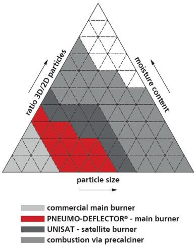
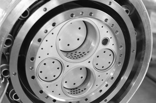
substitution rate (TSR) such as the Pneumo-Deflector or the UNISAT satellite burner. These dynamic burners are equipped with M.A.S. Technology, which provides a reliable and reproducible adjustment option with the highest momentum efficiency over the entire range. This gives operators the opportunity to optimise heat release and emissions according to fluctuating fuel quality.
Provide training for operators and maintenance personnel on the specific requirements and challenges associated with AF, empowering them to identify and address issues effectively.
By implementing these strategies, it is possible to effectively mitigate the challenges presented by the varying consistency and quality of AF, ensuring reliable burner operation while maximising efficiency and sustainability.
Satellite burners can play a significant role in modern cement production, primarily in enhancing the use of biogenic secondary fuel and therefore reducing environmental impact. Especially above a certain TSR (70 – 100%), the satellite burner is the tool for success. The following factors explain why this is the case:
f Temperature control: Together with a flexible main burner, satellite burners can be strategically placed within the kiln to provide localised heat input, allowing for more precise temperature control and uniform heat distribution even with very high substitution rates. This helps optimise the cement clinker formation process, leading to a more stable product quality.
f Fuel flexibility: Satellite burners offer flexibility in fuel selection, enabling cement plants to utilise a variety of AF, including biomass, waste-derived fuels, and other low-carbon alternatives. This diversification reduces reliance on fossil fuels, mitigates environmental impact, and enhances sustainability.
f Emissions reduction: By facilitating more efficient combustion and enabling the use of cleaner fuels, satellite burners contribute to lower emissions of greenhouse gases and pollutants, helping cement plants meet stringent environmental regulations and sustainability targets.
f Cost savings: By improving the TSR of secondary fuels, thereby reducing fossil fuel consumption, and minimising CO2 emissions, satellite burners contribute to cost savings for cement manufacturers in the mid and long term. Additionally, their modular design allows for easier installation, maintenance, and scalability, enhancing overall operational efficiency and profitability.
Overall, satellite burners offer numerous benefits for modern cement production, including enhanced
Finding spare parts like never before.

See what I see
fuel flexibility, emissions reduction, and operational flexibility. Their integration into cement kiln systems can help drive sustainable development and improve competitiveness in the global cement industry.
When looking at ways to decarbonise the cement industry, a diverse range of approaches has to be considered. Green hydrogen is one such approach, as the lack of any carbon involved in hydrogen combustion is well known. Using hydrogen, however,
is not without its technical challenges, particularly when used on a large scale. Focus must be placed on understanding and adapting to hydrogen’s thermodynamic characteristics (Table 1).
Control of flame propagation when using hydrogen is especially important as it has a flame speed eight times greater than methane and a very low density that results in a high nozzle outlet velocity of up to 1300 m/s (depending on pressure difference). This needs to be intelligently controlled in order to avoid double flame formation in combination with other fuels. Unitherm’s dynamic burners with their M.A.S. technology, are well suited to these conditions.
Several additional burner design considerations must be made to ensure safe and efficient combustion when working with hydrogen:
Hydrogen combustion produces high-temperature flames and can lead to increased corrosion rates and embrittlement of materials. Burner components must be made from materials compatible with hydrogen combustion, such as stainless steel or nickel alloys, to ensure durability and longevity.
Flame stability and propagation
Hydrogen has a wide flammability range and burns at a high flame speed. Burner design should prioritise stable flame characteristics to prevent flashback and ensure reliable, efficient and safe combustion over varying operating conditions such as start-up or full operation.
Heat management
To counteract the fast flame propagation which can impact temperature distribution along the kiln, the burner design, ideal with dynamic adjustment possibilities, should incorporate features to manage heat transfer, to obtain a similar heat distribution as with ordinary fuel mixes and maintain equipment integrity. By addressing these burner design considerations, cement plants can effectively leverage green hydrogen as a clean and sustainable fuel source while ensuring safe and efficient combustion processes.
Burner design plays a crucial role in minimising the production of harmful emissions, like NOx, in cement production. This section highlights some ways in which burner design can achieve the goal of reduced emissions:
f Efficient combustion: Proper burner design can optimise combustion efficiency by ensuring that the fuel is thoroughly mixed with the combustion air, resulting in complete combustion of the fuel. This can minimise the production of harmful emissions such as carbon monoxide (CO) and unburned hydrocarbons (UHC). Unitherm Cemcon’s burner designs are
engineered to provide efficient combustion, resulting in reduced emissions.
f Low-NOx technology: NOx emissions in combustion processes are mainly produced through temperature-driven reaction kinetics.
Unitherm Cemcon’s burner designs incorporate low-NOx technology, such as staged combustion, flue gas recirculation (FGR), which can significantly reduce the formation of NOx emissions at the main burner.
f Precise control: Burner design can also enable precise control of combustion parameters, such as temperature, excess air, flame shape and fuel-to-air ratio. This allows for optimal combustion conditions, minimising the formation of emissions.
Unitherm Cemcon’s burner solutions such as the M.A.S. technology incorporate advanced control systems that allow for precise and automated control of combustion parameters, resulting in reduced emissions.
f AF: Cement producers are increasingly using AF, such as biomass, waste-derived fuels, and other low-carbon fuels, to reduce their carbon footprint. Burner design can accommodate the use of AF by providing appropriate fuel injection systems like the Pneumo-Deflector© (Figure 4) when using AF through the main burner only or the UNISAT satellite burner when maximising the TSR between 70 – 100%, that ensure efficient combustion and minimise emissions. The sometimes-high moisture content in AF ‘cools’ the combustion process and thus leads to lower NOx emissions.
In summary, burner design plays a critical role in minimising emissions in cement production.
Unitherm Cemcon’s burner solutions are designed to optimise combustion efficiency, incorporate low-NOx technology, enable precise control, and accommodate AF, all of which contribute to emissions reduction objectives for cement producers.
To reduce maintenance costs and maximise the lifetime of kiln burner, the following steps can be taken:
Regular inspection and maintenance of the burner are essential to identify and address any potential issues before they become major problems. This includes cleaning, checking for wear and tear, and replacing worn-out components as needed. Unitherm Cemcon provides recommended maintenance procedures and schedules for its kiln burners, which should be followed diligently to ensure optimal performance and longevity.
Ensuring that the fuel and air quality meet the specifications recommended by the burner manufacturer is critical for efficient burner


performance and longevity. Poor fuel quality or contaminated combustion air can lead to increased wear and tear on the burner components, reduced combustion efficiency, and higher emissions, which can result in increased maintenance costs and decreased burner lifetime.
Following the recommended operating procedures and guidelines provided for the kiln burners is crucial to ensure optimal performance and extend burner lifetime. This includes proper start-up and shutdown procedures, correct fuel and air settings, and operating within the recommended temperature and pressure ranges.
Proper training of operating and maintenance personnel on the correct operation, maintenance, and troubleshooting procedures for Unitherm Cemcon’s kiln burners is crucial to minimise maintenance costs and maximise burner lifetime. Unitherm Cemcon provides training and technical support to their customers, which should be utilised to ensure that the burner is operated and maintained correctly.
Using genuine spare parts from Unitherm Cemcon for any repairs or replacements is important to ensure that the burner components are of the highest quality and designed specifically for the burner. Genuine spare parts are likely to have better durability and compatibility with the burner, reducing the risk of premature failures and minimising maintenance costs in the long run.
Automation and burner management systems significantly enhance burner operation through precise control, real-time monitoring, and safety features.
These systems enable optimal combustion efficiency, fuel savings, and product quality by controlling parameters like fuel flow rates and air-to-fuel ratios with precision. Real-time monitoring detects deviations from set parameters, allowing prompt corrective actions to maintain
optimal operation. Safety interlocks prevent unsafe conditions like flame failure or overpressure, reducing risks of accidents and environmental hazards.
Remote monitoring and control enable oversight and adjustment of burner performance from a centralised control room or mobile devices, improving efficiency and safety. Data logging and analysis provide insights for performance optimisation, predictive maintenance, and compliance reporting.
Integration with process control systems ensures coordination and optimisation of burner operation with other processes, enhancing energy efficiency and product quality. Energy management features optimise burner operation schedules, load distribution, and fuel switching strategies based on energy pricing and demand, minimising costs and environmental impact.
In summary, automation and burner management systems offer precise control, real-time monitoring, safety features, remote access, data analysis, integration, and energy management capabilities. These contribute to improved efficiency, reliability, safety, and sustainability in industrial burner applications.
Across the cement industry, there is a strong focus on reducing carbon emissions and improving energy efficiency in the cement industry, and this has led to the development of innovative burner designs (e.g. M.A.S. technology, UNISAT) that are able to efficiently combust an extraordinary amount of solid AF and emit fewer greenhouse pollutants.
This path will continue to be followed in the future, but at the same time the variety of fuel specifications is becoming ever wider, as certain fractions will no longer find their way into the combustion process in the pursuit of a functioning circular economy.
Additionally, the trend towards the use of gaseous AF, such as biofuels and green hydrogen, is likely to impact burner design.
These fuels have different combustion characteristics and require specialised burners to achieve optimal performance either under ambient or oxyfuel conditions.
Another trend that is likely to influence burner design is the increasing use of digital technologies, such as artificial intelligence and IoT, in industrial processes.
Burner manufacturers are likely to incorporate these technologies into their products to optimise performance, reduce downtime, and improve safety.


M. Akritopoulos and T. Abbas, Cinar, and Syed Suhail Akhtar, Holcim, explore the advantages of burning green ammonia over hydrogen in a cement kiln.
At cement plants, ammonia (NH3) is considered a pollutant in the flue gases or a reactant to reduce NOx. Its concentration in the atmosphere is monitored, a few parts per million (ppm) being of concern if it escapes without neutralising NOx to N2. A century ago, ammonia was needed to boost the yield of crops so it was produced commercially by combining H2 with N2 to produce NH3-based fertilisers. Used as a fuel, ammonia burns at a moderate rate leaving the combustion products of atmospheric N2 and water vapours.
But one may ask why not burn hydrogen without having to produce ammonia? The rationale behind this approach is the much lower transportation costs and existing infrastructure and transport facilities of ammonia, which do not exist for hydrogen, particularly if it is transported from off-site as a fuel to a plant. Therefore, production of green ammonia, using hydrogen derived from water electrolysis


powered by renewable energy resources cuts down the transportation costs. However, the production of green ammonia will cost up to four times as much to make as conventional ammonia, requiring further developments and ways to reduce green ammonia costs which in turn depend on its utilisation as a fuel other than as a fertiliser.

Ammonia has a higher energy density than hydrogen as a liquid with three hydrogen atoms rather than two. The energy density of liquefied hydrogen is 8491 kJ/l compared to ammonia’s 11 308 kJ/l.1 On a weight basis, ammonia contains 17.65% of hydrogen. As there are three hydrogen atoms attached to a single nitrogen atom, ammonia can contain about 48% more hydrogen by volume than even liquefied hydrogen. From a mass energy density basis, the hydrogen calorific value is 120 MJ/kg, compared to 18.6 MJ/kg for ammonia, which is similar to the calorific value of most green (biomass) solid fuels.1 This makes green ammonia an attractive renewable energy carrier as it has a higher energy density for lower transportation costs. Liquid hydrogen has to be stored at cryogenic conditions of –253˚C, whereas ammonia can be stored in much less energy-intensive vessels maintained at –33˚C. In addition, ammonia, though hazardous to handle, is much less flammable than hydrogen. Hydrogen production and transportation are limited especially when compared to a century-long use of ammonia in agriculture – a vast ammonia infrastructure already exists. Worldwide, some 180 million tpy of ammonia is produced, and 120 ports are equipped with ammonia terminals.
The production of green hydrogen through renewable sources, i.e., solar or wind, is an expensive option but may be justifiable under off-peak power conditions as well as considering CO2 mitigation costs. An alternative approach to the expensive storage and transport issues related with hydrogen, is to combine hydrogen into a compound that preserves the energy value but is easier to transport as a liquid, i.e., methanol (CH3OH) or ammonia. From a CO2 emission reduction perspective, ammonia is the obvious choice, having no carbon molecule.
Under good mixing conditions with oxygen, the only products of the complete oxidation of ammonia are water and nitrogen gas. At standard conditions (298 K, 1 atm), the enthalpy of combustion is 317 kJ/mol or 18.64 MJ/kg as compared with 240 kJ/mol or 120 MJ/kg for hydrogen.
Ammonia is regularly used in cement plants to reduce NOx (SNCR/SCR); however, it has not been used as a fuel. If fired in a kiln, a 100% ammonia flame would have a lower flame speed and a narrower flammability range compared to conventional fuels. It can also be co-fired either with H2 or other biomass-based fuels to reduce combustion generated CO2 emissions. However, it must be questioned whether it is a feasible choice. Ammonia as a fuel has never been fired in a cement kiln so its flame characteristics and
NOx formation potential are unknown, prior to full-scale plant trials. Thus, the use of ammonia as a fuel has been simulated in a cement kiln to evaluate its combustion characteristics as a co-firing fuel, in particular on NOx emissions.
To reduce CO2 emissions, cement plants are replacing carbon rich fuels, i.e., petcoke with

lower C/H ratio fuels as well as modifying the clinker factor to meet with the interim CO2 reduction targets set for 2030. The biomass and biological content in solid and liquid recovered fuels will become less available over the passage of time as other industries have also started competing for these fuels. As a result, the price of these ‘greener’ fuels is expected to rise and may eventually become restrictive and selective, thereby, making it unattractive for co-firing in large proportions. When this happens, green H2 and NH3 firing may be considered as a means to reduce CO2 emissions prior to tackling process generated CO2 emissions, i.e., oxy-combustion and/or CCUS.
A hydrogen flame would be shorter and hotter due to its higher adiabatic flame temperature, hence co-firing with a lower calorific value (CV) NH3, with some modifications in the kiln burner, would overcome biomass-based fuel shortage scenarios as a quick switch-over fuel. A disadvantage would be that, due to air-fuel mixing conditions, NOx formation through NH3 burning would increase. It is significant to highlight this increase, as well as the ways to minimise it – although kiln generated higher NOx emissions can be reduced later in the calciner through fuel reburning and/or using small amounts of NH3 (under selective non-catalytic reduction – SNCR or SCR). Under NH3 and H2 co-firing conditions, CO and NOx formation and destruction reactions rates and regions are expected to be different to those
analysed in one of the first full-scale modelling exercises of a cement kiln.
The limited data for air/ammonia/methane flames, under internal combustion engine or gas turbine combustor conditions for both premixed and non-premixed, shows the significant effect of fuel equivalence ratio on NOx formation. The reported trends show an increase in NOx emissions with a corresponding increase in NH3 content followed by a decrease in the equivalence ratio increases. These conditions are significantly different to those of a kiln flame. In the study presented, NH3 co-firing with H2 and biomass in a kiln burner was simulated and compared with H2 co-firing with biomass. The results are compared regarding the combustion, mineral compositions and NOx emissions.
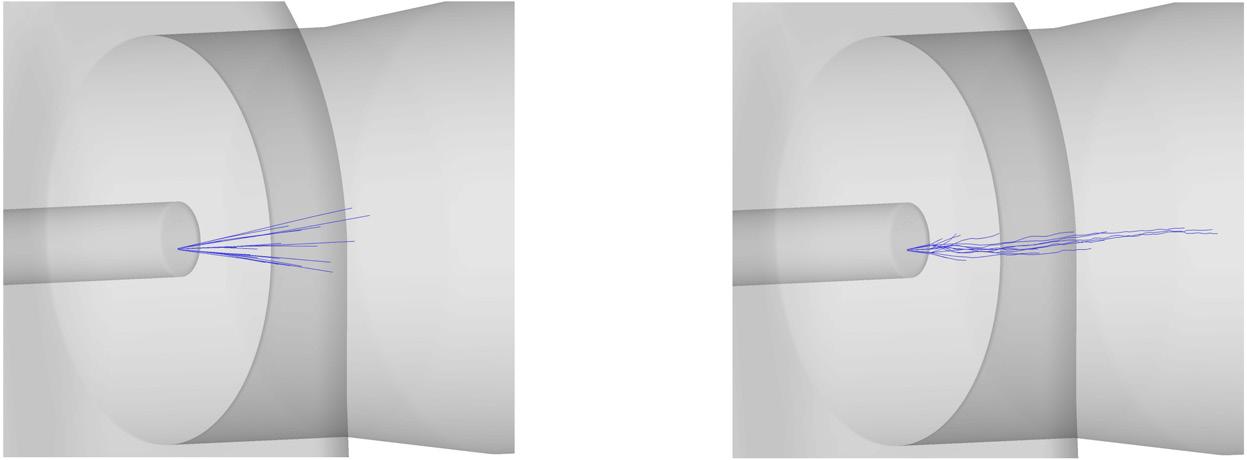
As part of follow-up research and prior to demonstration at full-scale, a sensitivity analysis was carried out for ammonia combustion in a kiln using mathematical modelling, to better understand its combustion and emission behaviour prior to performing expensive plant trials. As part of a recent research campaign, two new simulations are discussed here and compared with the previous H2 and biomass co-firing results which were validated against the plant trial data. Results of ammonia co-firing with hydrogen (Case 1) are compared with the initial simulation of H2 co-firing with biomass – the Base Case (Figure 1). In the Base Case, the biomass (liquid and solid biomass streams) was co-fired with H2 (25% by thermal input) and NH3 was co-fired with H2 with same thermal input ratio.
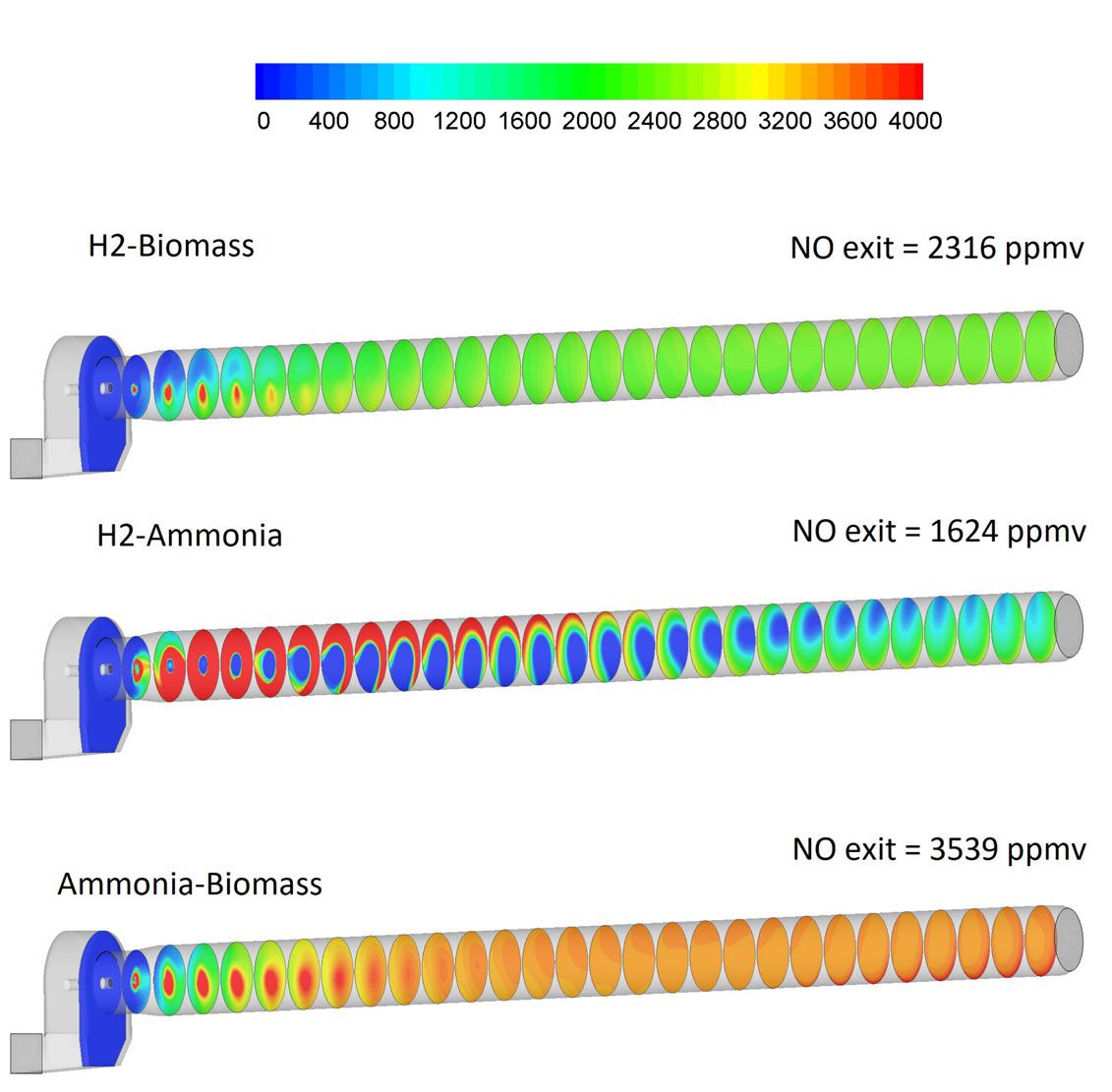
Figure 2 shows an absence of CO2 formation near the kiln front end, as hydrogen (25% by thermal input) co-fired with ammonia (75%) combusts without forming CO2. There was, however, some CO2 formation near the kiln feed-end – this was emitted as a result of calcination reactions of remaining uncalcined hot-meal particles, slowly calcining and releasing CO2. In comparison, three times the amount of CO2 was formed when H2 (25%) was co-fired with biomass corresponding to the carbon content of the biomass.
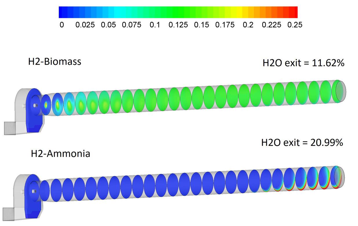
A higher proportion of water vapour formation was also observed (Figure 3) for the hydrogen/ammonia case, reflecting the absence of CO2 formation, as the combustion products were primarily N2 and H2O, seeing as the fired fuels were carbon-free.

Since stoichiometric combustion of 1 kg NH3 requires around 6.14 kg air and produces 1.59 kg H2O and 7.2 kg N2.
Co-firing ammonia with hydrogen also dampened higher gas temperature peaks (Figure 4) due to the higher adiabatic flame temperature of hydrogen as both gaseous fuels, in this case, burnt in close proximity. In the ammonia/hydrogen firing scenario, ammonia off-set the intensity of the hydrogen flame due to its higher substitution ratio and lower calorific values, i.e., less than 1/6 to that of hydrogen. The temperatures obtained in the ammonia/hydrogen flame were lower and the flame was less sharp and longer (hot region remains further) than the Base Case of hydrogen/biomass co-firing. Ammonia burnt fully while biomass fuel fractions burnt slowly and only up to 97% – for several kiln burner diameters distance. This led to an increased temperature at the kiln back end.
It was expected that the presence of ammonia would lead to a significantly higher NOx formation. Conversely, kiln feed-end NOx emissions dropped in the ammonia-hydrogen co-firing case (Figure 5). This was due to the suppression of peak gas temperatures, leading to lower formation of NOx through the thermal-NOx pathway. In addition, hydrogen, due to its higher reactivity, consumed most of the burner primary air, leaving little oxygen to oxide ammonia, which under starved air conditions was reduced to N2. Hence, reduction of NOx formed both thermal and fuel formation pathways.
In the second scenario, when ammonia was co-fired with biomass, NOx concentrations increased significantly due to the earlier ignition of ammonia in the presence of oxygen in the burner primary air stream. The biomass fuel was a mix of meat and bone meal (MBM -19.4 MJ/kg) and glycerin (CV-15 MJ/kg). For fair comparison, it is important to note that the fuel bond nitrogen content of MBM was five times higher than that of coal – since part of the biomass was burnt in oxygen-rich conditions of the flame in regions where secondary air diffused into the flame. In the ammonia/biomass co-firing case (Case 2), NOx contribution from thermal NOx reduced due to overall lower peak flame temperatures. The increase seen in the formation of NOx was therefore entirely down to the fuel NOx formation, as ammonia oxidised to NO upon predominantly reacting with the oxygen from the burner primary air (available in the absence of H2 combustion). Higher nitrogen content MBM particles released higher fuel bond nitrogen.
The results of the hot gases in the heating up of the bed material did show very similar trends for the three cases. In the case of ammonia/hydrogen, one small difference was that it resulted in a longer flame and lower peak temperatures.
However, heated gases remained at higher levels of temperature for a longer distance, while the bed material also heated up at a faster rate, the full calcination and formation of products occurring faster.
The rationale behind considering ammonia as a fuel is the extremely high cost of hydrogen procurement. Until these costs are justifiable, ammonia may be considered as a co-firing fuel either with hydrogen or biomass-based fuels. For example, in the plant trials, the cost of CO2 avoided (CaCO2) was €1559/t of CO2, which was estimated for a 40% hydrogen thermal substitution rate in the main burner, compared to 100% coal firing conditions. Hydrogen was responsible for about 87% of the fuel mix cost at the burner tip.2 It is difficult to quantify the cost savings of firing ammonia as there are multiple factors, i.e., the costs of long-distance transport, the technology used in the production of hydrogen and or ammonia, the green energy utilisation etc. The cost differential will become larger as the scale of projects increases, and as technologies are developed to reduce transport costs. However, in the absence of hydrogen transport infrastructure (and the prospects of energy savings to reconvert NH3 to H2 at the point of utilisation), it is not only energy efficient to burn ammonia directly, but co-firing it with hydrogen will also suppress peak flame temperatures due to its lower energy density.
Considering combustion and emissions, the presented results demonstrate the small-scale ammonia experimental findings, where 30% reductions in the NOx emissions are observed when ammonia as a fuel was fired in natural gas fired gas turbines.1 The mathematical model used in the predictions, has been validated earlier against the kiln trials for a number of hydrogen co-firing ratios with the biomass and coal as well as alternative fuel flames. Presented results demonstrate the effect of ammonia co-firing scenarios on emerging thermo-fluid dynamic conditions and how to tailor ammonia substitution ratio and its firing strategies to minimise its higher NOx formation potential.
1. JULIE et al, ‘The Potential Role of Ammonia as Marine Fuel – Based on Energy Systems Modelling and Multi-Criteria Decision Analysis’, Hansson, Sustainability (April 2020).
2. ‘State of the art fuel mix for UK cement production to test the path for ‘Net Zero’: a technical, environmental and safety demonstration’, chrome-extension:// efaidnbmnnnibpcajpcglclefindmkaj/https://assets.publishing. service.gov.uk/media/637e4d85d3bf7f154955962d/phase_3_ state_of_the_art_fuel_mix_for_UK_cement_production_to_ test_the_path_for_net_zero.pdf

Joel Maia, FCT Combustion, explores the different pathways available for producers to reduce CO2 emissions from cement and clinker production.
According to the Global Cement and Concrete Association (GCCA), the construction sector produces around 2.5 billion tpy of CO2, with the potential to increase to 3.8 billion tpy by 2050 without CO2 mitigation efforts, due to the rising demand for concrete. Approximately 60% of these emissions stem from limestone decarbonisation, with the remaining 40% from the combustion of fuels used in clinker lines. Additionally, electricity consumption contributes indirectly to CO2 emissions, when not produced renewably.
The construction sector’s value chain, encompassing Cembureau’s 5Cs (Clinker, Cement, Concrete, Construction, and Carbonation), holds significant potential to reduce CO2 emissions, striving toward carbon neutrality. Achieving this goal requires a
collective effort from all stakeholders, with clinker and cement production at its core.
The industry has already been moving toward decarbonisation for several years, employing various technologies. However, with numerous options available, plant environmental teams often feel overwhelmed, lacking clear information on the most cost-effective methods to reduce CO2 emissions for their specific circumstances. This article focuses on decarbonising clinker and cement production, exploring different possibilities and proposing scenarios tailored to each plant’s stage on the decarbonisation path.

CO2 emissions in clinker and cement production can be divided into two primary sources: emissions from raw material decarbonisation and emissions from combustion. Several strategies exist to mitigate both, discussed in this article. To facilitate comparison, a hypothetical ‘standard kiln’ with a 4000 tpd capacity, 800 kcal/kg thermal consumption, and a 40 – 60% energy split between the kiln and calciner respectively will be used, operating for 8000 hours per year.
Improving plant efficiency has a very broad meaning and influences all other methods presented as well. CO2 emissions are directly related to the amount of energy (thermal or electric), needed to produce 1 kg of material. Reducing the energy required to produce 1 kg of material lowers the fuel consumption and the volume of gases generated, thereby reducing both the thermal and electrical energy needed.
For instance, in the above-mentioned standard kiln, a 3% efficiency improvement would reduce CO2 emissions by approximately 14 000 tpy. It might not seem much but it is worth considering that a 3% improvement in the plant efficiency can be achieved by simple actions and low investment, through, for example, better process control, reducing false air in the system, optimising raw meal composition to allow for easier cooking, upgrading to a combustion system that allows the operation with lower oxygen content in the kiln while keeping the combustion under control.
Similarly, enhancing the clinker quality can lead to significant CO2 reductions. A better-quality clinker means that
less needs to be used to achieve the same cement strength. A 3% reduction in the clinker factor in FCT’s standard plant scenario would decrease CO2 emissions by around 34 000 tpy. Combining this with a 3% efficiency improvement results in a total reduction of approximately 47 000 tpy.
Methods to improve clinker quality include better process control, raw meal composition optimisation and homogeneity, and investing in advanced combustion systems such as the Turbu-Flex™ from FCT.
These options are often overlooked powerful alternatives, at relatively low costs, which allow plants to contribute to their initial share of CO2 emissions reduction.
Use of alternative fuels
It might sound counterintuitive that the use of alternative fuels (AF) would reduce CO2 emissions, as their combustion also releases CO2 While this is true, AF usage prevents additional fossil fuel consumption and the associated emissions. AF, often
instead of using a brand-new font of carbon taken from fossil fuels.
The use of AF is a mature technology, with plants in Europe being able to achieve up to 90% substitution rates by solid AF, and up to 100% when considering a mix of solid and liquid AF.
The cost of converting a plant to high substitution rates varies based on factors such as plant design,
existing equipment residence times, the quality of AF that can be sourced/prepared, and the technology of the combustion equipment, among others.
For this article’s standard kiln, a 10% increase in the thermal substitution rate replacing coal with RDF could reduce CO2 emissions by around 6000 tpy. Achieving a 90% substitution rate would reduce emissions by approximately 51 000 tpy.
Investments in CFD studies for the calciner and advanced combustion systems like the Turbu-Flex™ kiln burner from FCT are relatively low investments that can facilitate this transition.
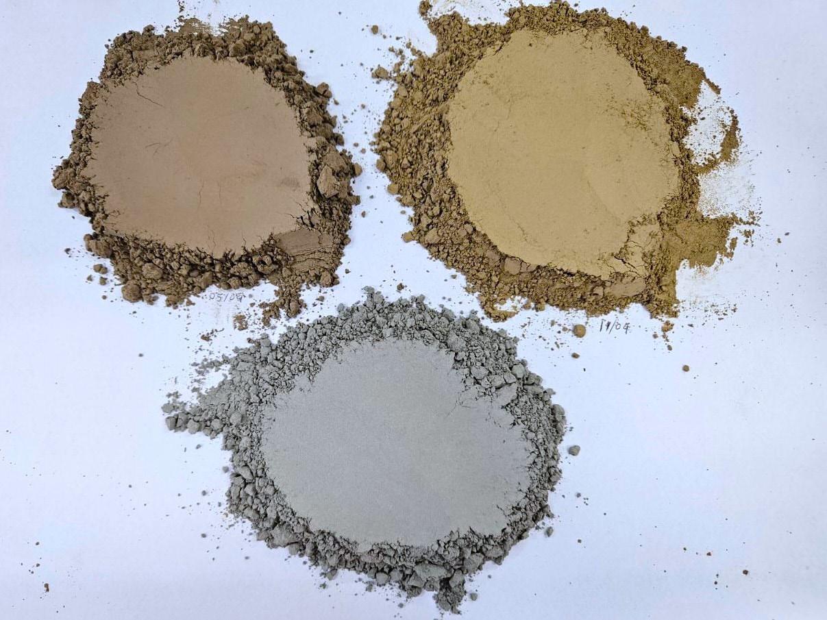
Materials that possess binding characteristics when mixed with water or other materials, known as supplementary cementitious materials (SCMs), have been used for several decades as a clinker replacement. Fly ash from power plants running on coal, slags from steel production and natural pozzolanic material are common examples of SCMs. However, their availability is decreasing, prompting the search for alternatives, with calcined clay being
a prominent option which has been used in cement for over 40 years in some countries like Brazil, for instance.
The clay used for the calcination is an aluminosilicate mineral within certain ratios of alumina and silica, containing hydroxyl in its structure. Once the clay is submitted to thermal treatment at the right temperatures, the hydroxyl is released from the clay structure. When the clay is mixed with cement, the calcium oxide from the clinker reacts with the clay, strengthening it. The right temperature for clay treatment is very particular for each clay, but in all cases, it is below the clinkerisation temperatures. Therefore, two benefits in terms of CO2 reduction can be achieved when replacing clinker with clay: the CO2 emissions from combustion are reduced (there are further benefits if AF are used), and there are virtually no CO2 emissions from the material (except for some organic and limestone traces).
Once more, the investment costs of this option are within a very wide range. On one side, existing clinker kilns can be adapted for clay calcination with minor adjustments, offering a cost-effective solution, although not the most efficient, even with a pendular operation between clinker and clay. On the other side of the scale, new plants using rotary kilns or flash calciner technologies can be built for optimal efficiency, with an array of different configurations. FCT offers the expertise of its engineers with more than 40 years’ experience in clay calcination, and technologies like the RotaCalx™ (rotary kiln) and FlashCalx™ (flash calciner) for clay production including colour control techniques.
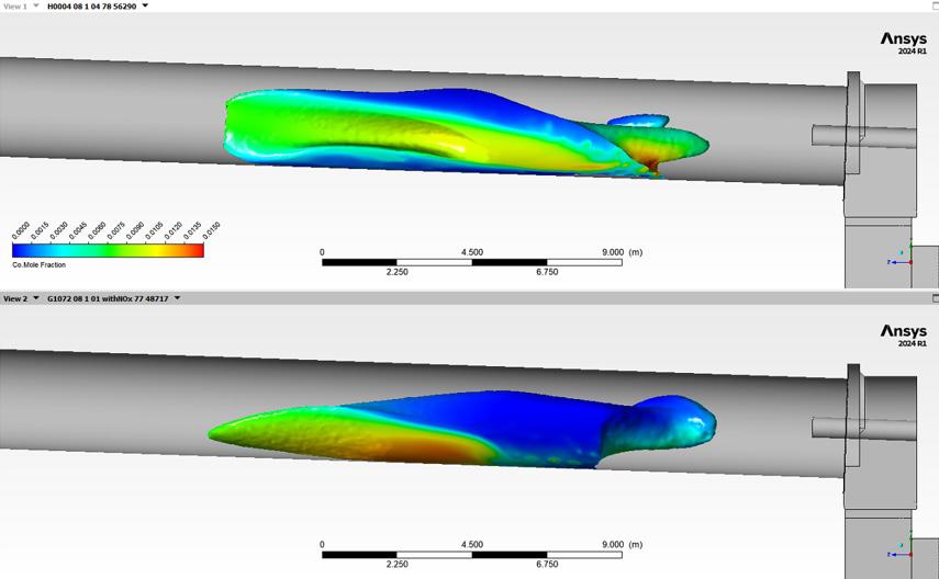
Combustion represented by an isotherm surface coloured by CO molar fraction, on top: oxyfuel combustion, at the bottom: conventional combustion with air. Source: FCT
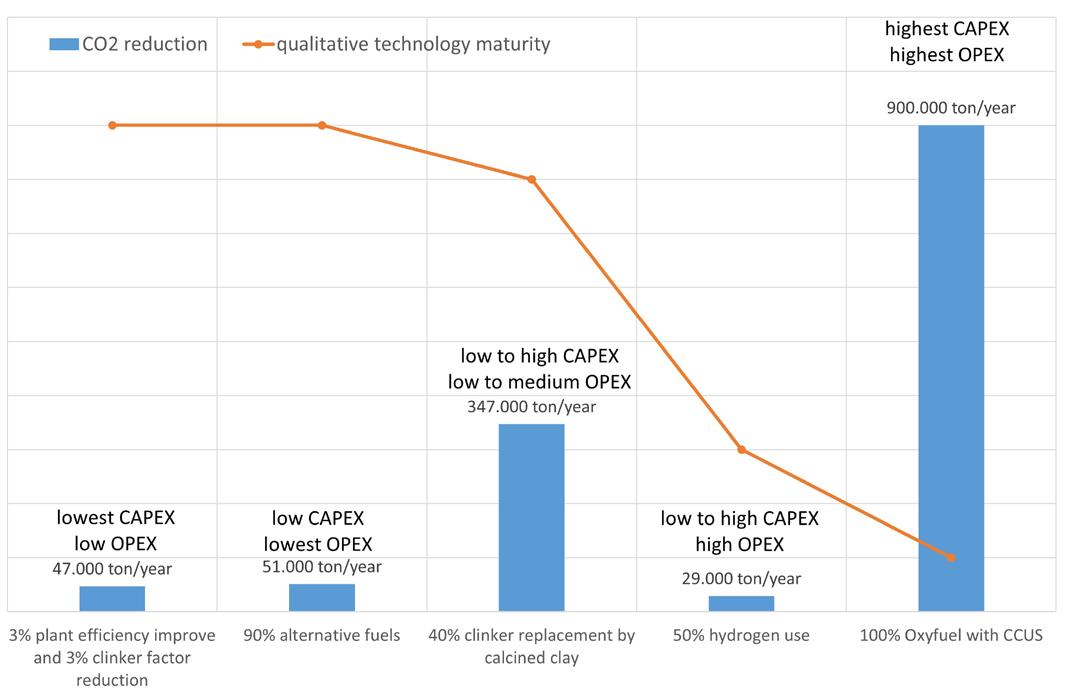
Comparison between different technologies for CO2 emissions reduction. Source: FCT.
For this article’s standard kiln, replacing 40% of clinker with calcined clay could reduce CO2 emissions by around 347 000 tpy.
Considering that hydrogen gas is a fuel that has no carbon, it should be considered ideal to reduce CO2 emissions. So far, the use of hydrogen in cement production has been limited to very small amounts, in the range of single digits of percentage, from 0.2 – 3%. The limitation is more in the production rather than in the combustion, especially when considering an environmentally friendly production of hydrogen.
Nowadays, the vast majority (above 99%) of hydrogen produced, comes from the reforming of natural gas which releases a substantial amount of CO2 into the atmosphere. If this is the case, burning natural gas directly in the kiln has a lower environmental impact. Moreover, hydrogen is still expensive compared to other fuels and is
not widely available to the industry, hence it is not a feasible option at the moment for cement production. If environmentally friendly hydrogen (for example, when produced via electrolysis of water using solar or wind power) became available at affordable prices in the future, there would be some challenges using hydrogen in cement production at a large scale. This would include reduced flame emissivity, increased NOx emissions and distribution infrastructure. However, these hurdles are significant only when achieving a substitution rate with hydrogen above 50%. There are important investments in order to make hydrogen production more affordable, in larger quantities and clean. FCT wrote a comprehensive article in WorldCementin November 2022 discussing the aspects around hydrogen usage in clinker kilns.
FCT’s burners are currently delivered for hydrogen use, ready for when clean and affordable hydrogen becomes available. For this article’s standard kiln, replacing 50% of coal with hydrogen would reduce CO2 emissions by around 29 000 tpy.
Oxyfuel combustion is a technology that can play a crucial role in reducing CO2 emissions in the cement industry. In a traditional cement kiln, fuel is burned in air, which contains about 21% oxygen and 78% nitrogen in volume. The nitrogen in the air does not contribute to the combustion process and instead ends up in the flue gas, diluting the CO2 concentration. Oxyfuel combustion, on the other hand, involves burning fuel with pure oxygen instead of air, recirculating part of the CO2 from the exhaust gases back to the cooler. This method results in a more efficient and intense combustion process and a significant reduction in nitrogen oxide (NOx) emissions. While oxyfuel combustion does not reduce the CO2 emissions, it does produce a flue gas that is rich in CO2, making it easier and more cost-effective to be captured and stored or utilised.
This technology is new and has challenges that need to be addressed, such as pure oxygen availability and costs, retrofit of existing plants as well as adaptations of the operational conditions.
Taking into consideration the standard kiln, implementing oxyfuel combustion could lead to a significant reduction in CO2 emissions. With the ability to capture a high percentage of CO2 from the flue gas using a carbon capture, utilisation and storage (CCUS) system, oxyfuel combustion could potentially allow the easier reduction of CO2 emissions by up to around 900 000 tpy, depending on the specific conditions and capture efficiency.
FCT burners are designed to operate under oxyfuel combustion conditions with minor adjustments.
There are a few initiatives in the field of direct electrification and use of thermal carriers to replace
combustion in clinkerisation processes. However, they are still very incipient when compared to the alternatives discussed here. The main challenges are to build reliable equipment and materials that can ‘deliver’ 1450˚C to the clinker, a reliable source of green energy throughout the year, and the large amount of MWs required for clinkerisation. For a combustion process, 100 MW for instance is easily and inexpensively achievable, while green electrification, from solar energy for example, would require a few square kilometres worth of solar panels, an electrical sub-station and all the maintenance associated with this equipment.
CCUS is seen as a major technology to help mitigate climate change by reducing greenhouse gas emissions from industrial and power generation sources by 2050. Industrial installations with different technologies are already in place, however, the high costs, energy requirements and necessity of practical experience remain significant challenges for its widespread deployment for the moment. The intensive investments in this technology could revert this situation in the next years.
There are several other technologies, still in their infancy, which require substantial research, investments and scaling up to allow for their industrial use. However, this topic is too extensive to cover in this article.
The cement industry faces significant hurdles to reducing its CO2 emissions, but numerous pathways exist to achieve substantial reductions, each one with its challenges, costs and CO2 reduction potential.
It is important to mention that the solution to enable CO2 neutrality is a combination of different methods.
Each plant is currently at a different stage of decarbonisation, each having unique circumstances that require tailored solutions. For instance, it would not make much sense for a plant to invest in calcined clay or hydrogen combustion, when the plant efficiency and use of AF are not maximised.
By improving plant efficiency, utilising AF, replacing clinker with SCMs, and exploring hydrogen use, alongside the new advances and technologies to come, the industry can move toward a sustainable future.
Joel Maia has graduated in Mechanical Engineering with emphasis in thermofluid dynamics and has a Master Degree in Business Administration in a double degree programme. For the past 25 years he has been working with combustion, especially in cement, executing projects in more than 60 different countries. Joel has been working in different positions throughout those years and now he is the CEO of FCT Combustion in their European Headquarters in Vienna, Austria.

Simon Thomsen, Leilac, explores the reasons for the cement industry’s hesitation to adopt CCUS technology, and explains how these challenges can be overcome.

It is no secret that the cement industry is difficult to decarbonise, being hard-to-abate for many reasons. CO2 is an intrinsic feature of cement manufacturing. To capture CO2 successfully, a technology must operate in harmony within a complex set of interrelated systems, each affecting the other. Combustion systems are stabilised against waste heat recovery modules to minimise fuel use. Precise clinker processes ensure industry-standard product compositions. The control room oversees a balance
between these systems. What is more, this balance is unique to each cement plant, and each cement plant is different from the next.
Carbon capture solutions traditionally involve large, rigid, and monolithic facilities. For a host plant, these new technologies can be difficult to integrate without disrupting operations. Some solutions impose a maintenance shutdown, to tie-in the apparatus as

an ‘end-of-pipe’ installation, while others require extensive plant re-configuration and auxiliary equipment. Some CCUS technologies are only feasible for newly built, state-of-the-art plants.
Perhaps the biggest hurdle to adoption, however, is the fact that none of these technologies have been proven beyond pilot scale. Given the challenges outlined above, a plant manager could be forgiven for hesitance – ‘Will this even work at our plant? Can we really afford it? Is any of this worth the commercial risk?’
There has been a sustained and praiseworthy effort from the CCUS research and development sector to adapt conventional CCUS technologies and make them compatible with a cement plant’s process. Innovative design and extensive modelling from a broad pool of technology companies have led to demonstrations in operational environments. These are necessary milestones, and this work has brought CCUS for cement to its critical juncture. Now, the technology must be proven in its intended commercial context; for the host plants tasked with integrating these projects, it could well be a daunting prospect.

The partial retrofit – a de-risked approach to integrating carbon capture
De-risking carbon capture for the host manufacturer should be an industry priority. Operational concerns form a major barrier to CCUS’s acceptance in cement. In order to see an increased uptake in these solutions, and a cleaner environment by proxy, then these technologies must be integrated in a way that is not disruptive to the producers absorbing them. CCUS solutions must be low risk, scalable and adaptable to the features of individual cement plants.
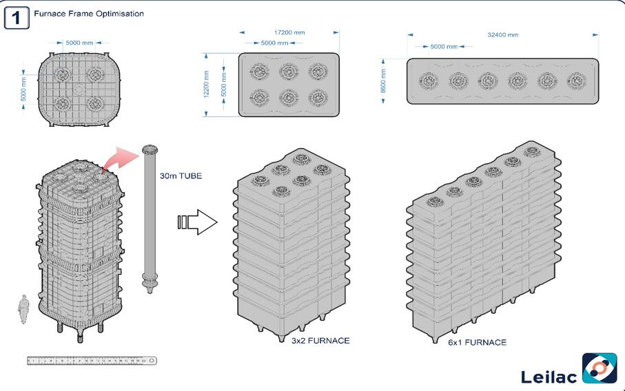
Examples of Leilac’s furnace configuration options.
One way of de-risking this integration process is to develop a technology that can be assimilated to the host plant’s process in incremental steps. By allowing the manufacturer to trial a CCUS solution, they can evaluate its suitability before fully absorbing it into their plant. Leilac’s core technology design facilitates this gradually integrated approach. In a hypothetical case where a mid-sized cement manufacturer wants to decarbonise one of their brownfield installations, given their wariness of undermining production commitments, the plant wants to start by trialling a single Leilac module, containing four calciner tubes. This could equate to just 20% of this plant’s raw meal inventory.
The other 80% would remain in the host plant’s established production stream. If, for any reason, the integration ran into difficulties, the consequences of this setback would be minimised. By lowering CCUS’s potential impact to production capabilities, in turn, the commercial risk of adopting such technologies is lowered.
And what if a CCUS technology could be integrated without extensive plant shutdowns? Commercial concerns aside, shutdown campaigns are a pain for the manufacturer, especially if it is tying in and commissioning a large and inflexible carbon capture facility. The host plant’s apparatus must be isolated, flushed and/or purged, broken into, re-configured, pressure assessed and re-commissioned. The risks associated with these operations to both personnel and equipment are significant in even the safest campaigns. By using a modular, potentially staged approach, Leilac seeks to reduce the operational commitment associated with CCUS. Leilac has designed its integration process to fit within a typical routine
maintenance campaign. A calciner can be built in advance of the shutdown, erected beside the plant’s preheater tower and tied in to pre-selected auxiliaries, to reduce installation time.
The manufacturer should be able decide if or when they scale up their decarbonisation campaign. It is important this decision can be balanced against other operational priorities. Following a successful trial period, scaling up could begin immediately. Alternatively, scaling up can be scheduled to mirror broader decarbonisation ambitions or requirements,
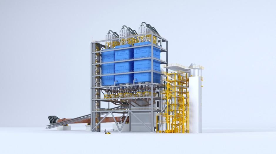
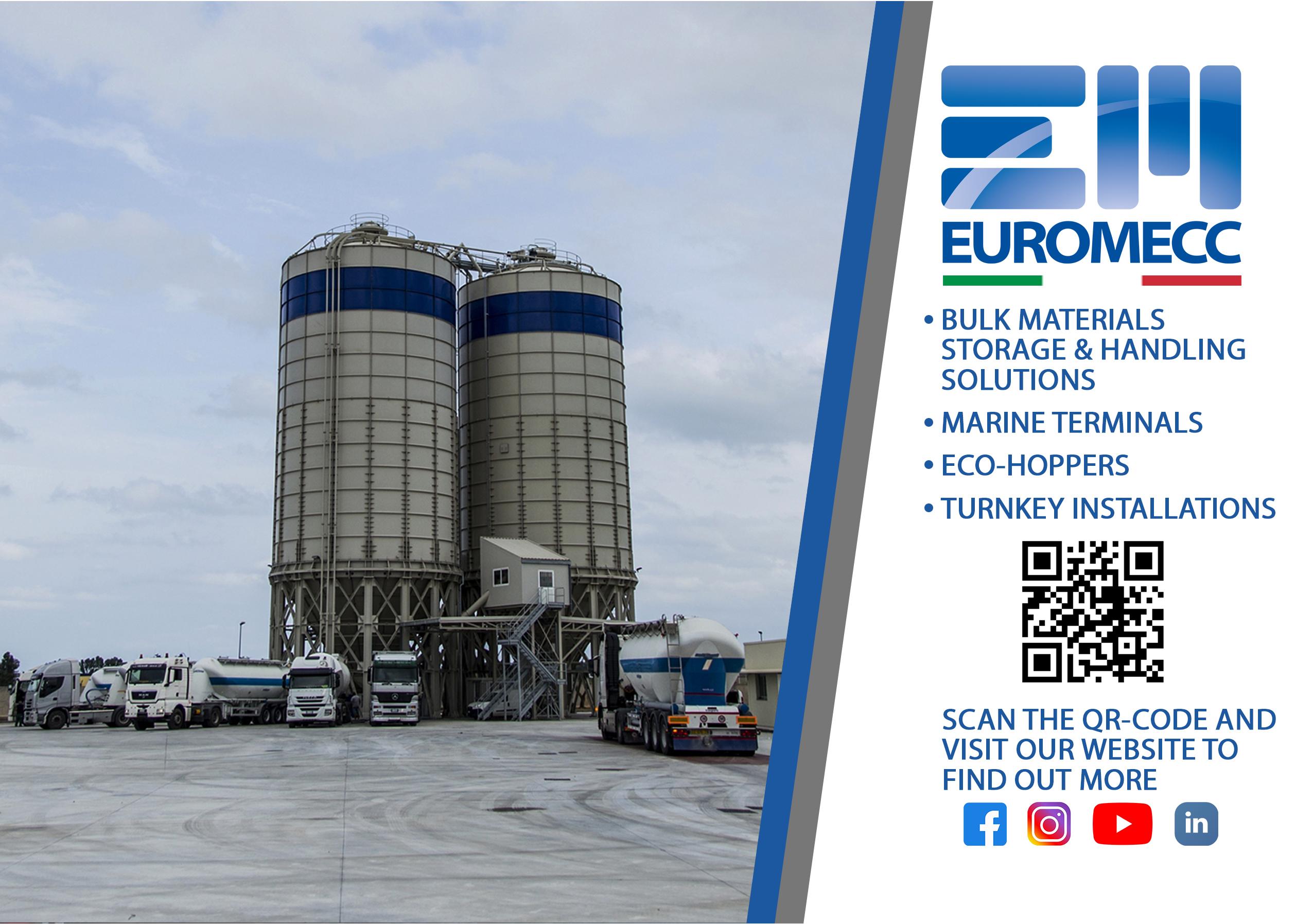
such as the phase out of free allowances under the EU ETS. A plant might balance their schedule against the expected local availability of CO2 transport and storage infrastructure. If this infrastructure is already in place, and the manufacturer wishes to decarbonise quickly, then a full-scale plant could be integrated immediately without a staged integration process. Making CCUS adaptable to the manufacturer’s priorities can help encourage industry-wide adoption.
Returning to the brownfield integration case, in this scenario, a Leilac calciner has successfully decarbonised 20% of the plant’s inventory. The manufacturer can then decide to increase their capture capabilities in further increments. Perhaps the plant wants to de-commission an ageing pre-heater tower, with a view to eventually replacing it with a full-scale Leilac plant. The Leilac plant could be scaled up on a module-by-module basis, increasing its throughput in roughly 20% stages, dependant on plant size. The inventory routed to the pre-heater tower could be gradually dialled back, thus maintaining a stable production train during the integration process.
Each cement plant has a unique site layout. A manufacturer will be concerned about the size and shape of the facility being built, and how that fits within available space.
To address these concerns, the modular nature of the Leilac technology enables calciner tubes to be arranged in highly flexible configurations. Like a game of Tetris, modules can be long and thin, square, clustered together, arranged in an L-shape and constructed around existing equipment, including the rotary kiln. Furthermore, these modules can be stacked or conjoined depending on the hosts plant’s preference. A host plant that wanted to prioritise a smaller footprint could opt for a taller, stacked plant – 13 x 26 m and a 100 m tower height. Or, if the host plant had concerns about height, they could choose a wider, shorter option – 26 m x 26 m and a 60 m tower height.
There is not a proportional relationship between a Leilac plant’s capture capacity and its footprint. As the company goes from one calciner tube at pilot scale, to a four-tube module at demonstration scale, to optimised multi-tube modules at full scale, more tubes can be incorporated into relatively smaller modules. Replicating a module on site to double the capture capacity does not mean duplicating all ancillary systems either. If the Leilac plant was scaled-up from one module to five modules, then the CO2 could still be processed by a singular end-of-pipe compression unit.
Leilac seeks to see its technology integrated worldwide. This is why the company has developed a technology that can run on a variety of energy
sources, including electricity, alternative fuels (AF), natural gas, solid fuels (such as coal & petcoke), biomass, and hydrogen.
The availability, price, and carbon-intensity of a given fuel varies by region and fluctuates over time. When integrating a Leilac plant, fuel options can be customised depending on market conditions, resource constraints and the host plant’s operational priorities.
The industry is trending away from heavy fuels, such as coal and petcoke, towards AF, such as municipal solid waste and biomass.1 Future greenfield plans may look to electrify their processes for a future-proof, low-carbon fuel option. But what if a brownfield installation wants to trial a new fuel source? Perhaps there are concerns about a fuel’s effect on the plant’s flue gas stream. De-risking integration could encourage the adoption of AF as well.
Leilac’s technology can integrate new fuel sources during the scaling up process. Given that the modules are compartmentalised, fuel sources can be trialled in a limited and partially isolated manner. The technology facilitates the calcination reaction through indirect heat. If the tube’s temperature profile remains stable, then the reaction is not affected by fuel choice. Leilac-2, a replicable four-tube module, is designed to run with over 95% AF use. Other Leilac projects are developing full electric multi-tube modules.
Host plants can opt for more than one fuel option to be available. If one of these options is electricity, the prospect of fuel switching based on market conditions opens potential additional revenue streams through load-balancing services to the grid.
Leilac’s technology development continues to support its future vision, including the development of suitable materials handling solutions and combustion solutions that enable 100% AF use at full-scale.
Tortoise beats hare
There is a sense of urgency. The cement industry has pledged to reach net-zero emissions by 2050, and to achieve that, the GCCA expects 1.4 billion tpy of CO2 will need to be captured. This means that over 1 million t of CO2 capture capacity for cement must be brought online, each week, between now and 2050.
This is not the time for industry hesitation. By de-risking integration and providing the manufacturer with customisable options and scalability, the sources of this hesitation can be removed. While it is imperative to act as quickly as possible to reach these targets, paradoxically, a gradual and scalable approach may be the fastest way to decarbonise cement.
References
1. CEMBUREAU, ‘Alternative Fuels’, https:// lowcarboneconomy.cembureau.eu/5-parallel-routes/resourceefficiency/alternative-fuels/

To start things off, tell us about CarbonFree’s background.
CarbonFree is a carbon capture company committed to the decarbonisation of hard-to-abate industries and global supply chains. We have invested more than 17 years into research and development to prepare our SkyCycle technology to capture carbon emitted from large industrial plants anywhere in
Martin Keighley, CarbonFree, answers some of World Cement’s questions regarding carbon capture technology and its potential for application in the cement industry.
the world. Our first plant, SkyMine, is the first and one of the largest industrial-scale carbon mineralisation facilities in the world, and has been operating alongside a cement plant in San Antonio since 2016. It captures up to 50 000 tpy of CO2
We view SkyMine as a ‘proof of concept’ for mineralisation that made the invention of SkyCycle possible. SkyCycle is more scalable and profitable because it produces a
zero-carbon mineral that not only provides a more resilient way to sequester carbon dioxide, but also has

greater market demand, in comparison to SkyMine that produces sodium bicarbonate, or more plainly known as ‘baking soda’.
CarbonFree will deploy its first SkyCycle plant in the next two years. In the next five years, CarbonFree aims to be operating its initial fleet of plants globally, demonstrating that carbon capture can be done effectively and profitably with impact beyond just the carbon emissions captured.
How can you help cement & lime producers reduce their CO2 emissions?
With the cement industry responsible for 8% of global carbon emissions and the expectation that emissions will increase with demand, the industry is poised to evaluate solutions to decarbonise operations in order to continue thriving.
The cement industry in particular is difficult to decarbonise given that 60% of the emissions generated through cement manufacturing are process emissions, which are inherently linked to the chemical reactions involved in cement production and are not easily avoided through energy efficiency or switching to renewables alone. This is why it is necessary to have a mix of pragmatic solutions, including carbon capture.
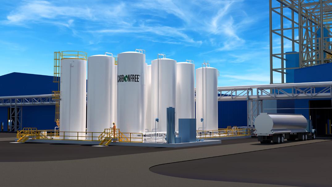

This is where CarbonFree comes into play. Our SkyCycle technology is designed to capture carbon from large industrial emitters that the global supply chain relies heavily on to help them decarbonise. Compared to many decarbonisation technologies, SkyCycle is also commercially available now and can be online within the next two years.
This technology can also help reduce Scope 3 emissions for manufacturers. The captured carbon dioxide from source emitters is converted into high-value, zero carbon chemicals that can be sold into the global chemicals market, driving profitability, and decarbonising the supply chain for a number of materials, including paper, plastics, ceramics and more.
How does the SkyCycle process work? Talk us through the technology involved.
SkyCycle is designed to be co-located on the property of any industrial plant that we partner with. The solution captures untreated flue gas straight from a plant’s chimney, which then comes into contact with magnesium hydroxide. This creates an immediate reaction that produces magnesium bicarbonate.
The magnesium bicarbonate reacts with calcium chloride to produce magnesium chloride and zero carbon calcium carbonate. The calcium carbonate can be used in a variety of manufactured use cases such as papers,


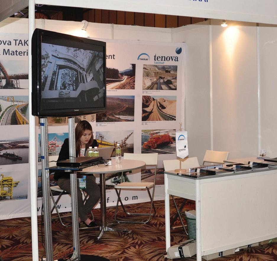


plastics, food products, and paints. Any surplus calcium carbonate can also be stored in resource-depleted locations such as abandoned quarries without releasing any carbon back into the atmosphere. Finally, the magnesium chloride is heated and then decomposes into hydrochloric acid (HCl) and magnesium hydroxide. The HCl is used in the production of calcium chloride and magnesium hydroxide, which are both recycled back into the process to produce more calcium carbonate and magnesium chloride. The entire process takes place without the use of long pipelines or storage wells.
How can this technology be applied to cement & lime plants? Would changes to the production process be required?
The process used to capture carbon alongside cement and lime plants would be the same as what is described above. With that said, SkyCycle can potentially use waste materials produced by cement and lime plants in its process. For instance, CarbonFree will use slag produced by its partner’s US Steel’s blast furnace operation as part of the calcium carbonate production process. Waste lime can also be used as a calcium source for SkyCycle.
The zero-carbon mineral produced via this process can also be useful for the cement industry. Early testing has shown that it can be used as a SCM for creating high-strength concrete.
SkyCycle is the only carbon capture, utilisation and sequestration technology on the market today that combines both carbon capture and utilisation into a single process. Direct air capture (DAC) solutions need an additional solution for carbon utilisation once the carbon is captured, and sustainable aviation fuel (SAF) needs a solution to capture the carbon for utilisation.
Compared to many other scalable technologies, we can help hard-to-abate industries like cement reduce their carbon footprint within the next two years. SkyCycle plants are also easily scalable at a reasonable operating cost and can be applied to a wide range of industrial host sites. Our first plant captures 50 000 tpy of CO2 minimum, and within the next two years will be scaled to 250 000 tpy of CO2.
A major differentiator and benefit of this technology is that it can help reduce waste materials for the plants that use them and reduces Scope 3 emissions for the companies that manufacture with calcium carbonate. For instance, CarbonFree will be using slag produced by the blast furnace process in US Steel’s Gary Works facility as part of the calcium carbonate production process, which would otherwise sit in a landfill. Selling zero-carbon minerals also makes SkyCycle profitable without relying on government subsidies, which is critical for long-term growth and scale of decarbonisation solutions.


What are some milestones that you’re proud of? What are some future plans for the company that you’re excited about?
This April, CarbonFree signed a definitive agreement with US Steel to capture carbon emissions generated from US Steel’s Gary Works Blast Furnaces in a first-of-its-kind project. Projected to begin operations in 2026, the SkyCycle project will capture and mineralise emissions that are equivalent to what is produced by nearly 12 000 passenger cars annually.
Last year, we also announced that bp, which has been a CarbonFree investor for nearly 10 years, entered into a collaboration agreement with CarbonFree to identify and develop carbon capture and utilisation projects around the world to deploy SkyCycle technology.
We are at the point where we are looking for a new partner in cement to do further development with, similar to our partnership with US Steel. We’re currently talking to several small and large global cement players.

Main Theme: Integration of Triple Transformation
Sub-themes:
Cement Sector and Decarbonization
Green Transformation in Energy
Cement and Digital Transformation
Next Generation Cements
Innovation and Advanced Technologies
Other Industry Topics
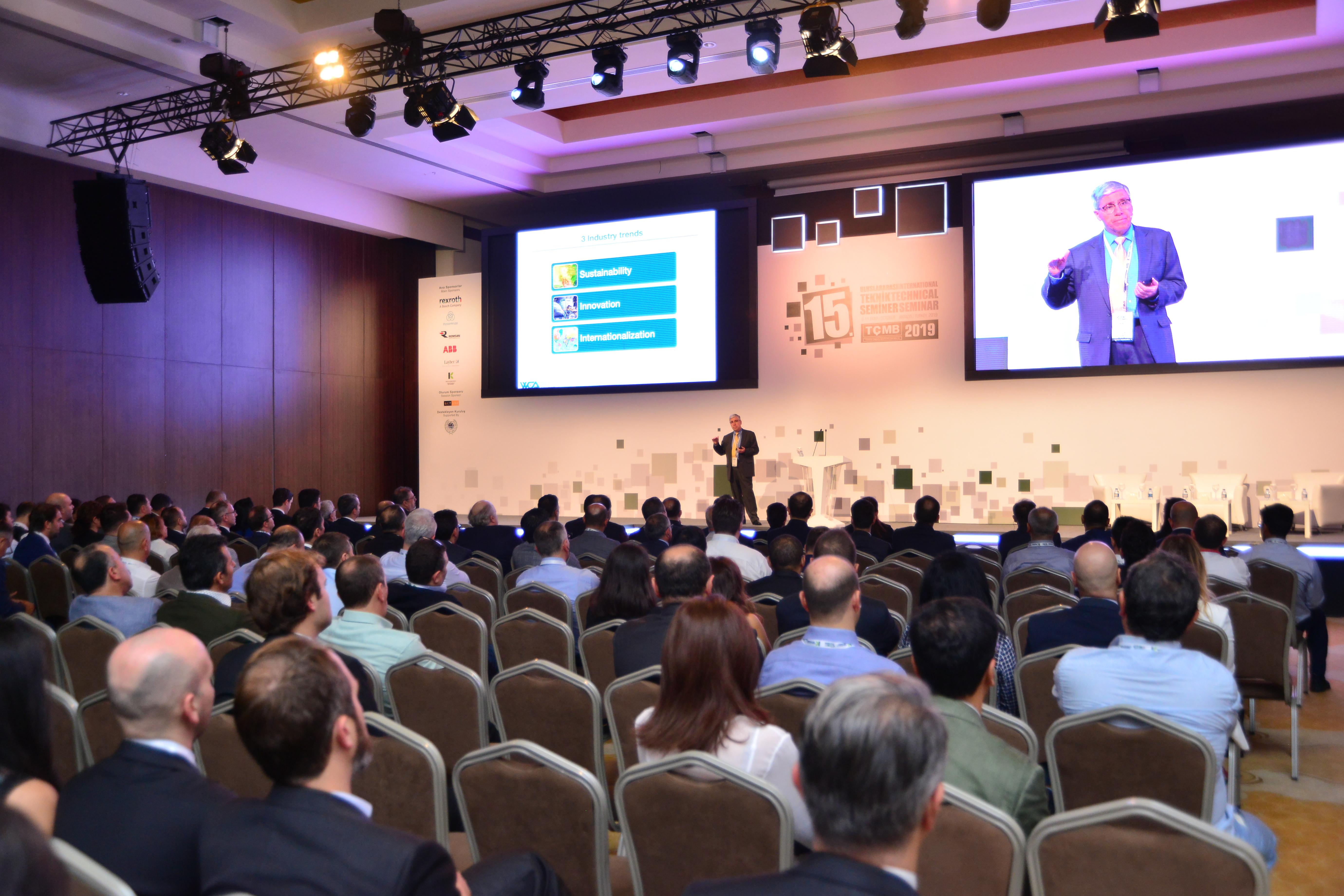


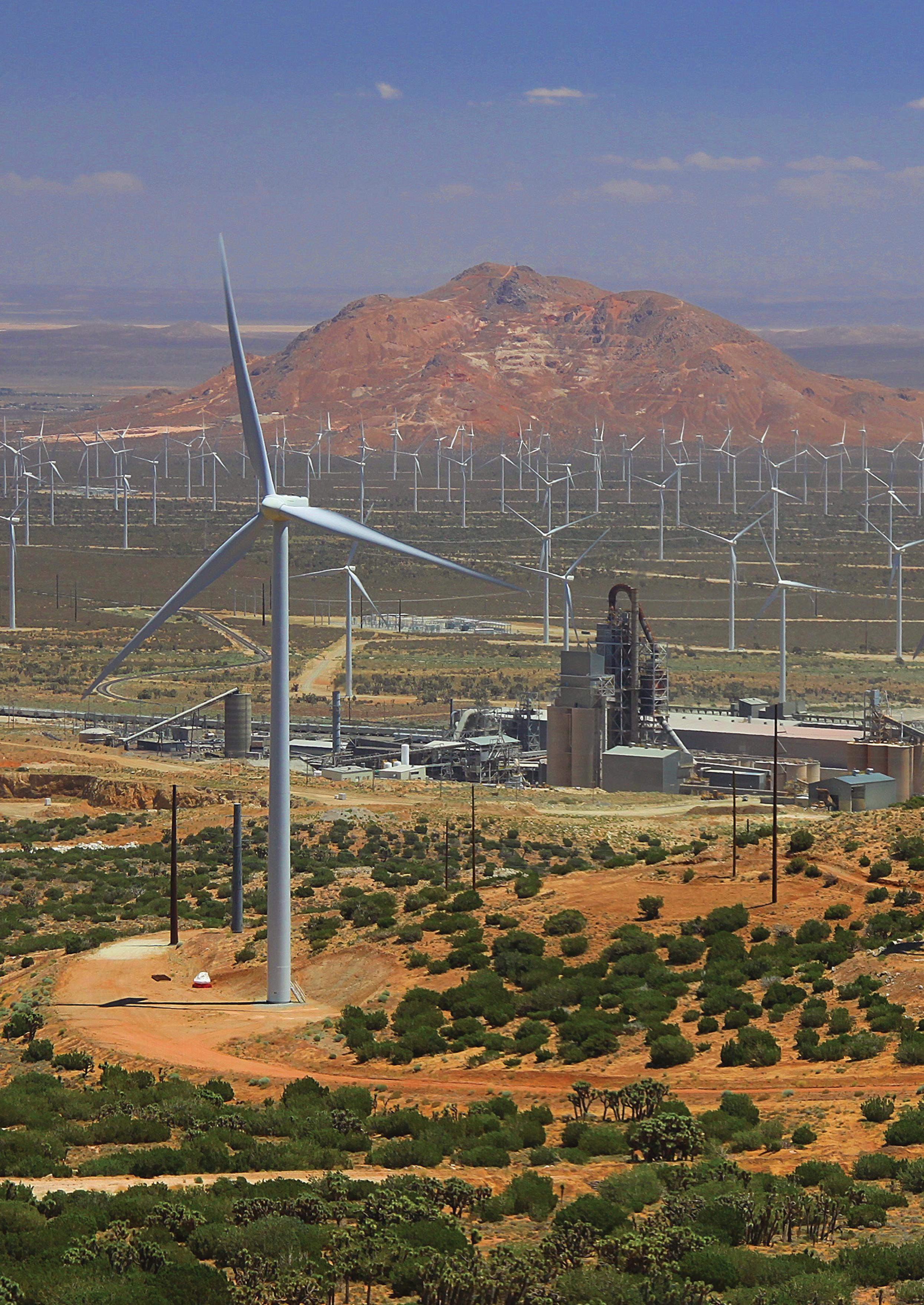

Hamed Maraghechi, CalPortland, discusses the development of ternary blended cements in California, contributing to cement decarbonisation efforts.
To reduce the environmental impact of cement and concrete materials, one of the most effective approaches is the widespread production, adoption, and use of low clinker cement formulations. The production of clinker is the most carbon-intensive part of cement manufacturing. Clinker is produced in high temperature kilns at ~1450˚C, often heated by the burning of fossil fuels. Limestone (a rock rich in calcium carbonate – CaCO3) is a major raw material component, that decomposes to CO2 and CaO in an intermediate step through clinker manufacturing. Clinker is often not hydrated fully in concrete even after many years, and the residue acts as a filler, though it may slowly hydrate, resulting in an increase of compressive strength beyond 28 days. As such, a portion of clinker can be replaced by supplementary cementitious materials (SCM). Portland cement-based concrete has the lowest carbon intensity among industrial materials per unit weight. Due to its excellent performance, and reasonable cost, high demand and the use of cement and concrete materials by the growing world population are key global drivers for the high emissions associated with cement and concrete materials.
In order to achieve its carbon neutrality goals, CalPortland is in the process of developing low

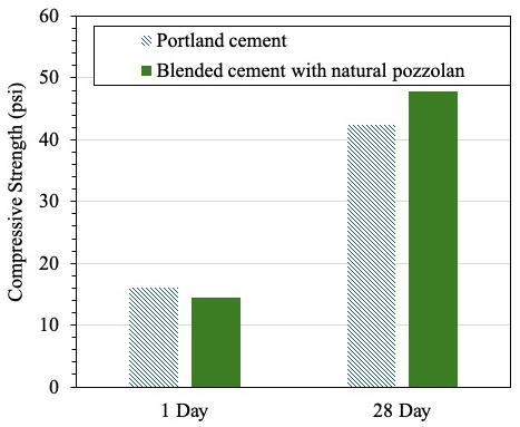

carbon cement and concrete products. CalPortland has already introduced Portland limestone cement (PLC or IL), which has proven success in reducing the carbon footprint of concrete. However, to further reduce the global warming potential of concrete, the current focus is on achieving higher clinker reduction by using natural pozzolans.
After several years of research and development, ADVANCEMENTHPT, a tailor-made low carbon cement formulation designed with four main components: clinker, gypsum, natural pozzolan, and limestone, was created. This blend is designated as an ‘IT’ blended cement (an ASTM C595 specification), which is the dominant standard in the US. Use of natural pozzolans in concrete is not a new practice. In fact, before fly ash became a popular ingredient in concrete, many regions in the Western US, such as California and Nevada, were using natural pozzolans. Use of natural pozzolans expanded during the early-to-mid 1900s, in various public works projects including numerous dams and the Los Angeles Aqueduct.
Main classes of natural pozzolans include volcanic ash, perlite, pumice, zeolite, clay, and shale. There are many decades of proven field performance of concrete, where natural pozzolans were used in their cement formulations. Such a history of excellent performance assures the suitability of IT cements made with natural pozzolans for widespread applications. Larger agencies such as departments of transportation, and state and federal agencies, have accelerated their interests, adoption, and allowance for formulations like this developed by CalPortland.
The presence of natural pozzolans in blended cement (e.g., ADVANCEMENTHPT) results in superior durability characteristics in concrete infrastructure, when compared to Portland cement. This is derived from the refined micro and nano porosity of hardened concrete due to the formation of more, or different phases. Refinement of porosity significantly reduces the rate of diffusion of aggressive ions such as chlorides from sea water or deicing salts, or sulfates from the soil in contact with concrete. Such an improvement will extend the service life of concrete. Unfortunately, such attributes are often neglected when accounting for sustainability indicators of concrete structures and materials. Natural pozzolans can be milled with, or separately from, other cement ingredients. ASTM C618 defines the specifications of pozzolans for use in concrete.
Following Product Category Rules (PCR) derived from ISO standards, the LCA of cement and concrete products provides certified documents known as Environmental Product Declarations (EPD). Currently, EPDs only consider
cradle-to-gate, the production stage (A1-A3) –i.e, extraction of raw materials (cradle) through the manufacture of cement ready for shipment (gate). In other words, they do not encompass increased durability and service life, as well as the CO2 absorption of concrete. Regardless of this, reduction in environmental impacts (CO2 eq.) of ADVANCEMENTHPT compared to Portland cement, is calculated to be 25 – 30% lower. Increased durability of concrete structures, and consequently the sustainability and environmental impacts of concrete structures are important attributes of blended cements with natural pozzolans.
The ADVANCEMENTHPT formulation is also designed to provide similar or better early age and long-term strength and flow characteristics compared to Portland cement-based concrete (Figures 2 & 3). This is linked to the microstructure of the blended cement, and the custom-made ingredients.
There are various methods for evaluation of flow characteristics of cement-based materials. While the slump test is the most conventional one, more advanced tools, such as rheometers are being employed by manufacturers to better design the formulations. An example illustrated in Figure 3 shows a very similar flow curve for an IT cement, as compared with Portland cement. Durability performance of ADVANCEMENTHPT is significantly higher than Portland cement.
Examples include higher sulfate resistance, (an important requirement in California), higher resistance against chloride ion transport (Figure 4) in concrete and increased corrosion resistance, and reduced alkali-silica reaction expansion of reactive aggregate. All these can increase the service life of concrete by several decades.
The suitability of a pozzolan is linked to its reactivity, but also to its location, and consistency in quality. Examples of quality attributes include the extent and rate of reactivity of pozzolan (or SCM), its
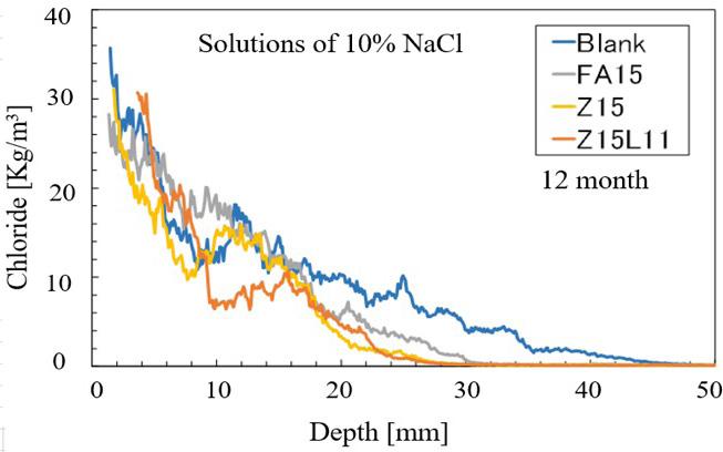
Figure 4. Chloride ion penetration profile in concrete exposed to highly concentrated saline solution. FA: fly ash, Z: natural Pozzolan, and L: limestone. Test results provided by Taiheiyo Cement Corporation.

influence on fresh state, as well as hardened and long-term behaviour. A newly developed test method (ASTM C1897) estimates the contribution of pozzolans in concrete, by measuring the exothermic reaction heat in a model system. CalPortland’s pozzolan shows a higher heat and reactivity than conventional fly ash products (Figure 5).
Natural pozzolans are rich in amorphous and crystalline minerals that are typically rich in alumino-silicates and participate in several hydration reactions in conjunction with clinker, limestone and gypsum. As such, the composition and assemblage of hydrates may include further formation of more (secondary) calcium silicate hydrate C-S-H, which is the primary binding phase in concrete. Natural pozzolans react with calcium hydroxides produced during the hydration of clinker, forming additional C-S-H (pozzolanic reaction). Calcite from limestone can provide carbonates to form AFm phases, and the extent of which depends on sulfate and aluminate content. Increased aluminate content of calcium (aluminate) silicate hydrate C-A-S-H are further chemical attributes of such compositions. Because of such chemical properties, natural pozzolans make a dense and durable concrete.
While the development of blended cements is perceived as a ‘low-hanging fruit’ approach towards carbon neutrality, there are various sorts of technical and non-technical challenges with such developments.
f For a producer of cement, providing consistent quality and quantity is essential. Almost always, capital and operational investment is needed (e.g., in new milling systems, materials process and handling, such as conveying belts, lifts, and storage, etc.).
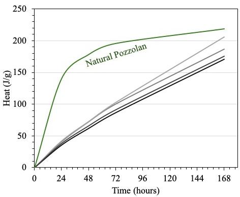
Figure 5. Reactivity of natural pozzolan, tested using isothermal calorimtery method described in ASTM C1897.
f Obtaining the required environmental permit to mine natural pozzolans is a tedious and lengthy process, and can decades, especially in regions with strict regulations, such as California.
f Like almost all other man-made products, new cement formulations have different behaviour than currently used Portland cement. Training, communication, collaboration and engagement of all stakeholders, specifically cement and concrete producers, and contractors are essential for faster adoption. Concrete mixing procedure, heat of hydration, and curing optimisation are examples of possible features that need to be adopted by following scientific guidelines and manufacturer’s recommendations.
Concrete is the second most used material after water which highlights the need for meaningful change, development, and adoption of new technologies.
Efficiency in the use of cement and concrete, regardless of clinker content, is challenging in key regions of the world (e.g., Southeast Asia) where use of bagged cement is a common practice. Often high w/c, high cement content, and improper curing is associated with practices of using bagged cement, all affecting durability and sustainability of the end-use product.
In addition to the development of low carbon cements, CalPortland’s stewardship towards sustainability is recognised through sustained energy conservation and efficiency. CalPortland utilises wind energy at its Mojave cement plant by employing eight wind turbines that can generate up to 24 MW of electricity to support the operations.
Other decarbonisation strategies include shifts to the use of non-fossil-fuel based materials. California is suffering from a huge excess of biomass materials to the extent that CalFire conducts controlled burns in the forest to reduce the wider fire hazard. Rotting and formation of methane is a consequence of compiling biomass, which has a much greater impact on global warming, compared to CO2
In a pilot scale project, CalPortland is exploring pyrolysis to convert biomass into biofuel, to further reduce its CO2 eq. by a further 20%, if fully implemented within its Southern California plants.
Carbon capture utilisation and storage (CCUS) may complement total decarbonisation, however, the technologies are not yet well-established. To capture CO2 in a concentration suitable enough for transport, for the purpose of storage underground, various
technologies are being developed by industries and research centres. The need for availability of a pipeline is a key step and a prerequisite that, when clarified by governmental and regulatory agencies, can help accelerate this approach.
CO2 utilisation encompasses different forms and definitions. Examples include mineralisation of CO2 in recycled cementitious materials, such as demolished or returned concrete. Such construction demolishing waste materials are abundant and provide a unique potential in a circular and low carbon economy. Hydrated cement and anhydrates are rich in phases that can react with a CO2 stream to provide solid products with high reactivity potential.
The products are negative for CO2 and when used in preparation of blended cement can have a significant contribution to reduction of CO2 eq. of cement and concrete materials. CalPortland is currently starting a pilot project at its Mojave cement plant, where recycled concrete fines will be used to mineralise CO2 from stack gas stream. Extensive laboratory research has demonstrated that carbonated products, not only being carbon negative, also provide reactivity and hence can be used as an ingredient in the manufacturing of blended cement.
CalPortland’s commitment towards a sustainable and circular economy has been recognised for 20 consecutive years by the ENERGY STAR® Award programme, and the United States Environmental Protection Agency (EPA). CalPortland is keen to
continue its contribution towards carbon neutrality by pursuing development and implementation of impactful science-based solutions.
1. DOWNEY, CAMERON, and KOHLER, S., ‘Mineral Land Classification of the Long Valley Pozzolan Deposits, Lassen County, California.’, 2003, Special Report 177. Sacramento, CA: Department of Conservation, California Geological Survey – https://www.conservation.ca.gov/cgs/Documents/ Publications/Special-Reports/SR_177-MLC-Report.pdf.
2. ‘Los Angeles Aqueduct’, 2019 – https://www.history. com/topics/landmarks/los-angeles-aqueduct.
About the author
Hamed Maraghechi, PhD, is the Vice President of R&D and Decarbonisation at CalPortland Company. In his role, he leads various decarbonisation levers and projects to support CalPortland’s sustainability goals and commitment to decarbonising cement production. Hamed also oversees CalPortland’s Corporate Central Research Laboratory located in the Southern California.
Hamed holds a PhD in Civil and Environmental Engineering from The Pennsylvania State University and has authored several scientific publications. Hamed has worked in several countries and contributed to the advancement of various companies, developing new materials, products and solutions for the construction industry.


Concrete is the most widely used substance on the planet besides water. It is critical for building roads, dams, bridges, airports and other infrastructure. The downside of this versatile material is manufacturing cement – the binding ingredient in most concrete mixes – accounts for about 8% of all man-made greenhouse gas emissions worldwide.
There is already an innovation in cement that stands to dramatically lower the concrete industry’s carbon footprint.
Eco Material Technologies has developed multiple green cement products that can be manufactured with significantly lower carbon emissions than traditional Portland cement. These green products function as a substitute for cement in the production of concrete in significantly higher proportions than traditional supplementary cementitious materials (SCMs).
Traditional Portland cement is made by mining virgin limestone and clay and heating the material in giant kilns at approximately 2700˚F. The energy-intensive process, which is often powered by fossil fuels, releases almost 1 t of CO2 for each ton of material manufactured. By contrast, Eco’s green cement manufacturing process does not rely on an energy-intensive kiln, eliminating inefficiencies and extreme energy requirements. Since green cement requires significantly less electricity per ton manufactured than Portland cement, its associated carbon emissions are significantly lower. Unlike cement manufacturing, green cement does not generate and release CO2 via the decomposition of calcium carbonate (CaCO3).
Green cement products are manufactured using fly ash – as well as natural pozzolans and other minerals – from multiple sources. However, Eco utilises a reactor system to process the raw materials and ensure a consistent manufactured product. Pre-treatment of fly ash with a chemical additive improves the product’s strength and performance characteristics, after which the material is ground to the ideal size for optimal reactivity.
PozzoSlag® is a highly reactive modified pozzolan that meets both ASTM C989 performance specifications and ASTM C618 performance specifications for Class F fly ash. Comprised primarily of Class C and F fly ash, PozzoSlag is approved by the Texas Department of Transportation and the Federal Highway Administration under a special provision as a Modified Fly Ash allowing for up to 50% Portland cement replacement.
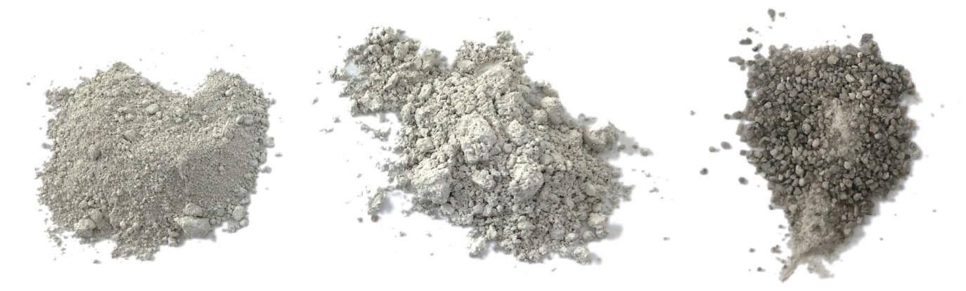

By contrast, most current SCM products typically replace approximately 20% of the ordinary Portland cement used in concrete. PozzoSlag reacts quickly, matching the performance of Portland cement after one day and achieving 20% greater strength after 28 days. This green cement is typically utilised in ready-mixed concrete as a replacement for Portland cement in construction projects such as highways, bridges and concrete products, such as pipes.
Comparing compressive strength trials of PozzoSlag to Portland cement.
PozzoSlag 3.0J is a special-purpose SCM product that is designed for use in fast-setting controlled low-strength material (‘flowable fill’) and similar applications. Comprised of Class C fly ash, the product takes as little as 15 minutes to meet 100 – 250 psi strength requirements. When used in 3-to-4 sack mix designs, PozzoSlag 3.0J attains 50 – 80 psi compressive strength (ASTM C109) in one day and 150 – 250 psi in 28 days, depending on sand quality. It can be designed and formulated
to meet the target strengths for specific project needs.
PozzoCem® and PozzoCem Vite, Eco’s 3D printer cements, achieve 3000 psi in 7 days and 5000+ psi in 28 days. These products can replace up to 100% of the Portland cement that traditionally would be used to manufacture concrete, while avoiding approximately 90% of the carbon emissions associated with Portland cement production.
Concrete made with green cement displays numerous performance benefits compared with that made from Portland cement. These advantages include the following.
f Lower permeability, which improves durability, due to:
» Better particle size distribution/density from improved packing factors.
» Improved chemistry and stoichiometric balance of the concrete binder.
» Reduced alkali-silica reactivity because of its chemistry and densification due to reduction of pore structures.
» Mitigated delayed ettringite formation.
» Reduced chloride intrusion, lowering corrosion of rebar and other metallic components due to density and reduced pore structure.
f Improved sulfate-resistant performance because of:
» The chemistry of pozzolans and high pozzolan replacement of cement.
» Reduced alkali-silica reactivity/improved durability.
» Improved ASR mitigation owing to green cement’s high pozzolanic reactivity and reduced chemical elements and alkalis that contribute to ASR.
» Reduced water-cement ratio and densification, which prevents water intrusion and helps mitigate ASR reactions.
f Reduced shrinkage cracks because of:
» Reduced bleed channels that trap water and slow shrinkage (slow curing).
» Improved early strength.
» Reduction in calcium hydroxide.
» Lower water demand.
f Improved workability, pumpability, and finishing because of:
» Spherical shape of fly ash.
» Decreased water demand.
f Lower set times and improved long-term strength because of:
» Smaller particle size/increased BET surface area for reactivity.
» Greater contact between reactive materials.
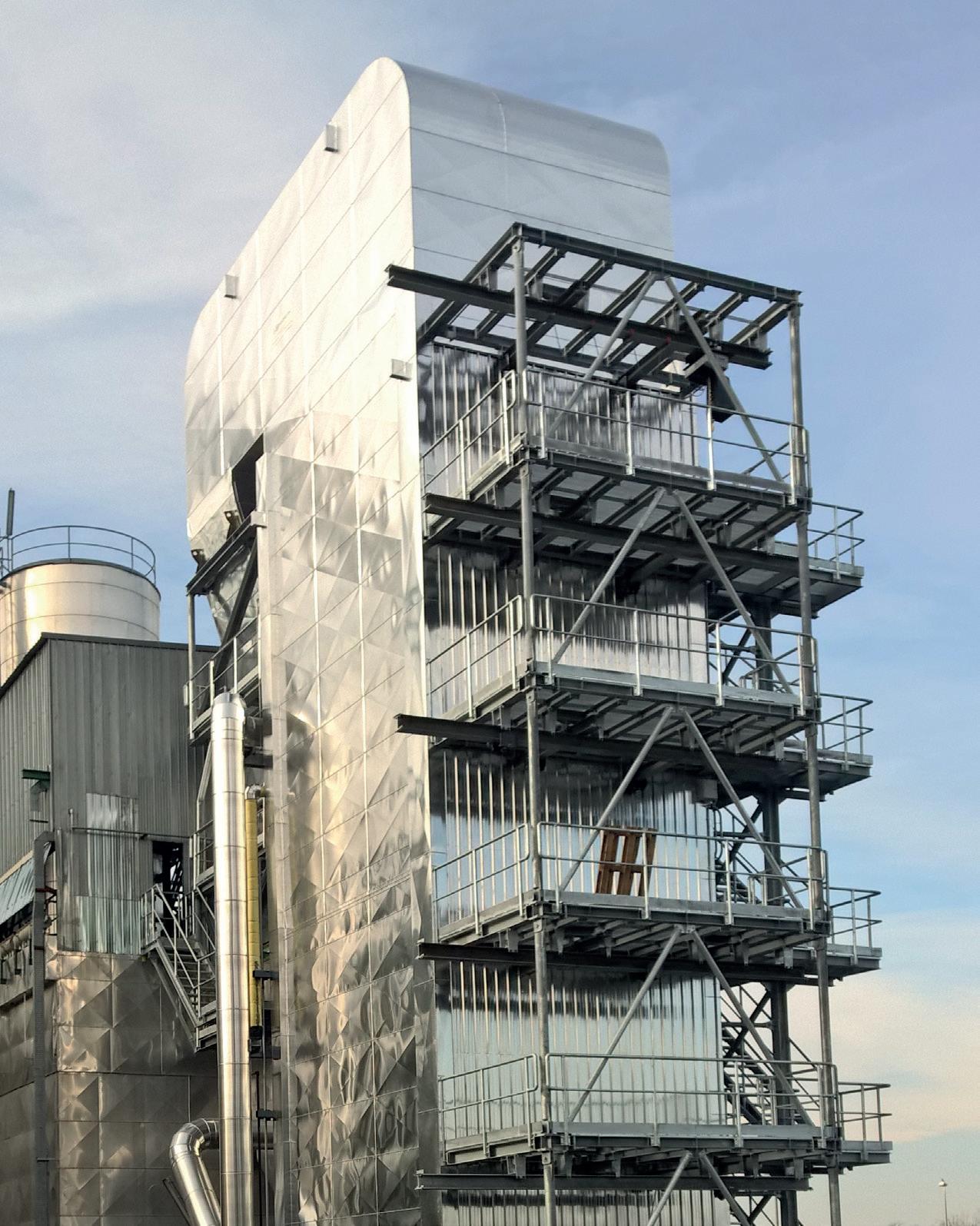
» Faster rate of cement hydration and pozzolanic reactions, which increases long-term strength.
f Fewer surface problems in concrete, such as dusting and delaminating as a result of reduced bleed water.
Beyond these performance benefits, concrete made from Eco Material’s green cement products will typically cost less to produce compared to those made from blended cements because of its ability to be used in higher replacement ratios than most traditional SCMs. Furthermore, concrete made from green cement can reduce contractor labour costs because the concrete will be easier to work with at lower slumps and will set faster, allowing reduced hours for finishing.
Eco Material currently manufactures green cement products at its facility in Jewett, Texas, while a second plant is now under construction
in Lakeview, Oregon. The Lakeview facility will use natural mineral (pozzolan) feedstock to produce PozzoSlag. Set for completion this year, it will have the capacity to produce 300 000 tpy of green cement. The plant will utilise a mill for pre-grinding to produce PozzoSlag that meets ASTM C989 specifications after processing and can be marketed as a stand-alone 50% cement replacement product. The plant will also have the capacity to produce an ASTM C618 quality natural pozzolan in lieu of PozzoSlag, should that product offer economic advantages for specific projects.
Eco Material currently has nine plants that are either operational or under construction. Together, these plants represent more than 4 million tpy of production of novel, beneficiated SCMs and green cement products to help decarbonise the North American concrete market.
More than 1 million t of Eco Material’s green cement products have been used in construction projects throughout the US over the past decade. They require no changes to current industry practices and have been validated by the US Department of Transportation (DOT), Texas DOT and the Pennsylvania DOT. In Texas alone, PozzoSlag has been used in highways, roads, building foundations, airports, down hole cement and precast concrete products.


The company’s green cement products are also now being used to construct 3D-printed houses in Round Top, Texas, southeast of Austin. Eco’s PozzCem Vite, utilised as part of the construction of The Casitas @ The Halles, replaces 100% of the Portland cement traditionally used to produce concrete, has 90% lower emissions associated with its manufacture and sets in as little as 2 – 3 minutes, allowing for rapid printing of sustainable homes. In addition to the environmental advantages of the material, a mobile, small-footprint construction printer and mixing system was developed to dispense Eco Material’s green cement at industry-leading speeds,
allowing the builders to print at lower costs compared to other commercially available 3D printing mortars. In October 2022, a 3150 ft2 home in nearby Burton, Texas was built using PozzoSlag at lower cement replacement levels. The Burton house features several innovations never attempted before in a 3D-printed house, including parametric wall designs, foamcrete wall insulation and pigmented concrete layers.
A 2023 report by Precedence Research has valued the green cement market at US$620 million annually. It is expected to grow to above US$1 billion by 2033, and that growth will be fuelled in part by governmental ‘buy clean’ policies. Under such policies, government agencies at the federal and state levels are required to purchase construction materials that have been shown to reduce carbon emissions. The Federal Buy Clean Task Force, which is comprised of 14 agencies and accounts for 90% of construction materials purchased by the federal government, integrates ‘buy clean’ practices in procurement decisions. Such policies will provide major economic support for low- and no-carbon cement.
As the United States and other governments pursue a lower carbon future, many traditional
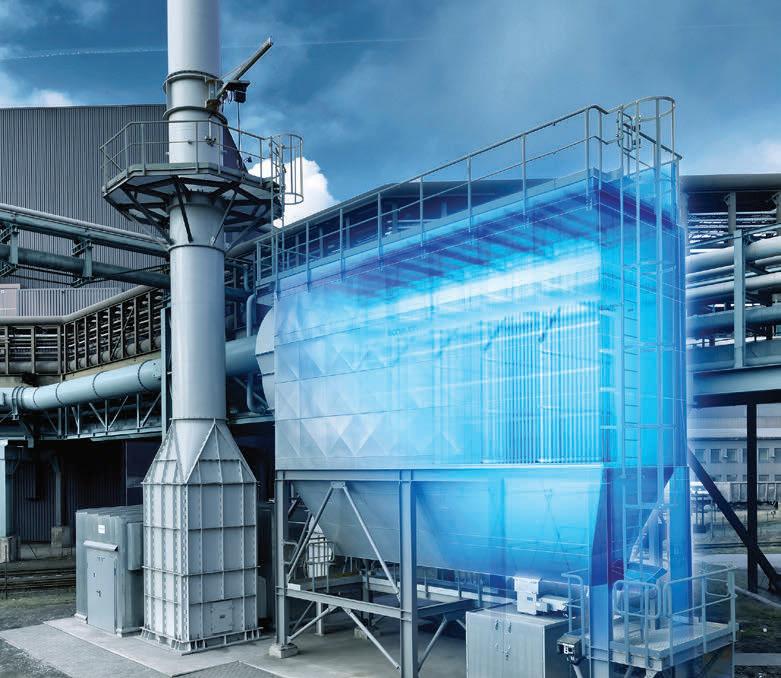
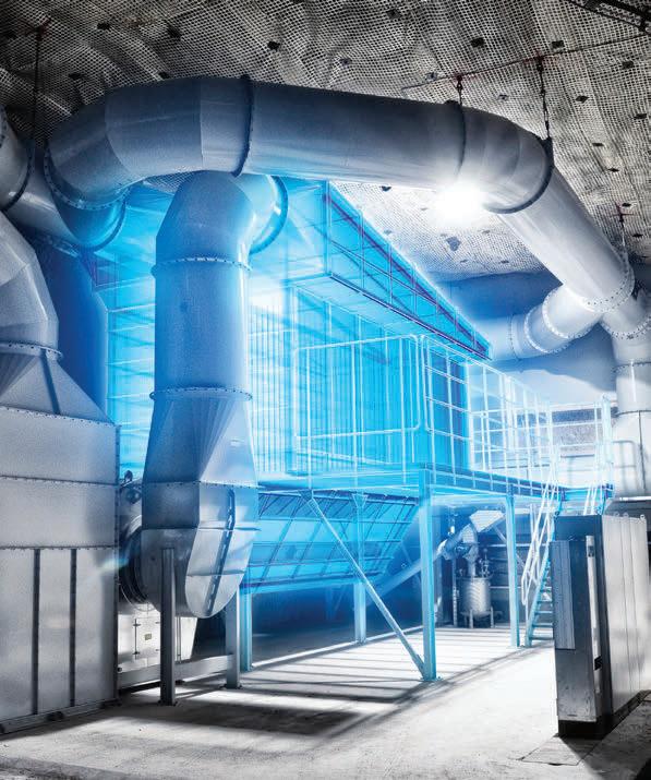
coal-fuelled facilities are being shuttered. As more plants are retired, the availability of fresh fly ash and other coal combustion products decreases.
That is no cause for worry, however.
Eco Material’s sources for harvested ash are set to supply material for its green cement products long into the future, since an estimated 2 billion t of ash is currently stored in about 1000 sites across the country. Eco is bolstering these supplies with additional sources of input material for its green products, including natural pozzolans and minerals, of which many billions of tons are available.
Currently recycling 10 million tpy of material from 100+ sites across 45 states, and with the industry’s only true national footprint of terminals, storage, and distribution channels, Eco Material is well positioned to play a key role in helping decarbonise the construction industry.
Grant Quasha is Chief Executive Officer of Eco Material Technologies, a leading producer and supplier of sustainable cement alternatives in North America.
Formerly, he served as Chief Executive Officer for Green Cement LLC. He received his B.A. from Harvard College and an MBA from Harvard Business School.


Reiner Bachthaler, Axians Industrial Applications, explains how mobile applications can be highly beneficial in bulk goods industries.
Operational requirements in the bulk goods logistics sector are becoming ever more dynamic and the time pressure is increasing. Many different roles and users are involved here, and the integration of individual solutions for sub-areas into an ecosystem is becoming indispensable.
In addition, users of software logistics solutions are no longer just office users for whom desktop software is suitable. Many users are either on the road, in the production plant, or at construction sites and, therefore, need the flexibility to be able to carry out their logistics tasks anywhere,
even without a laptop or desktop PC. Of course, this also applies to truck drivers transporting bulk goods. They too should no longer receive their information only via paper delivery notes, but should become part of the digital logistics workflow. It is clear that the demand for mobile solutions in bulk goods logistics is very high and is constantly growing. This should also be seen in the context of a heightened awareness of sustainability and the demand for a paperless logistics workflow. While this increased demand should not be a problem, as there are plenty of apps on the market, many apps are stand-alone solutions

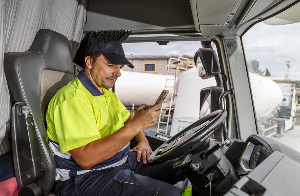
and are not integrated with central, higher-level workflow systems. This leads to manual data entry, a lack of transparency and inconsistent data. In that case, mobile apps are just another tool, but not a real game changer for the above requirements. In other words, if a bad process is digitised, a bad digital process is the result.
The solution is the seamless integration of mobile apps with central logistics workflow systems such as Axians VAS Cloud Logistics, or the online connection to plant logistics solutions such as Axians VAS Yard Management.
This means that the data in the app is always up-to-date and consistent, moreover, data entered in the app can also be transmitted immediately and automatically to central systems and many different users. This means maximum transparency and greater process reliability with significantly reduced costs.
The following is a brief description of typical use cases for mobile apps in bulk goods logistics and the associated solution, as well as the benefits that can be achieved.
f Challenge: To make order entry more secure and flexible compared to current practices (often ordering by phone call or email), i.e. no more restrictions in terms of office hours and flexibility if, for example, a site manager wants to order material for the next morning late at night in the middle of the construction site. Carriers or dealers could also use such an app to place orders on behalf of the customer, so there are many possible applications and roles.
f Solution approach: A mobile app, that enables quick and easy online ordering, based on order contracts between customer and supplier, with a direct connection to a

central, cloud-based order entry and planning system.
f Benefits: A fast and secure ordering process with maximum flexibility, transparency and a low error rate.
f Challenge: Not only should the order process be covered by such an app, but full transparency over the entire lifecycle of an order/delivery and central availability of all relevant documents (e.g. delivery bills, invoices, etc.) should be achieved.
f Solution approach: An order taking app must be significantly expanded to enable the use of relevant data in the app, that is managed in the ERP or plant logistics systems through full integration with a central cloud logistics system.
f Benefits: The customer has all the relevant information available at exactly one point. This leads to improved customer loyalty and less effort for the customer and supplier for any clarification and information procurement.
f Challenge: Mobile loading and unloading vehicles in the delivery plant and also on the construction site (like wheel loaders and forklift trucks) require reliable information on deliveries and the delivery process (customer, material, quantity, order no., license plate number of the truck, etc.) and must also record the data on the actual loading process. Today, this is often done completely manually, e.g. with paper-based pre-delivery notes, that have to be filled in by hand. This is time-consuming, error-prone and unsustainable.
f Solution approach: Wheel loader and forklift truck drivers receive all relevant information from superordinate logistics systems online in the Mobile Loading App and can immediately identify and select the upcoming delivery. The loading data (quantity, time stamp) is also recorded in the app and automatically transferred online to central systems.
f Benefits: Significantly reduced effort for data recording during loading and unloading, as well as greater security (the risk of incorrect loading and incorrect data entry is minimised) and an improved CO2 balance, as no printouts are necessary.
f Challenge: Truck drivers who carry out deliveries in bulk goods logistics often struggle with incomplete information, a multitude of papers (pre-delivery ticket, loading note, delivery note, etc.) and high time pressure. Drivers therefore need reliable, up-to-date

Cement plants all over the world rely on Alimak rack and pinion elevators to provide reliable, efficient vertical access for maintenance and inspection Designed to operate in demanding industrial environments, outdoors and indoors, Alimak elevator s require no expensi ve shafts or machine rooms, and they can easily be installed on new and existing structures Standard capacities range from 30 0 k g to 7,0 0 0 kg, with up to 24-ton capacity available upon request
Contact us at info@alimak.com for further information.
information on their deliveries without having to rummage through paperwork, and a way to record delivery data easily or even completely automatically.
f Solution approach: The journey to the loading plant, check-in and check-out at the plant, the loading process itself, the journey to the recipient and the recipient’s confirmation of receipt of the goods (ePoD) can all be handled in a Driver App. The driver receives all the necessary information about his to-do list (delivery list) in the app, selects the upcoming process and can also check in and out at self-service terminals in the plant or start the loading process using QR codes from the app, e.g. in conjunction with a plant logistics solution such as Axians VAS Yard Management. Status messages (e.g. ‘Arrived at loading plant’) can also be set automatically using existing geolocation data with a GPS connection. Whether the Driver App is connected to a central logistics workflow

solution such as Axians VAS Cloud Logistics, or to a plant logistics solution, must certainly be evaluated individually in different use cases. In general, however, the connection to a central solution certainly allows greater flexibility, especially when used across multiple delivery plants.
f Benefits: Significantly reduced administration effort for truck drivers (but also for the admin in the loading plant), faster deliveries, shorter dwell times in the plant, greater safety and better sustainability thanks to a paperless workflow.
Ticket App
f Challenge: The focus here is on the paperless handling of delivery information (PDF-based delivery ticket + metadata) and can therefore be seen as part of the Driver App, but with possible applications not only for the driver, but also for other roles, such as the goods recipient.
f Solution approach: After loading at the delivery plant, a delivery note is no longer printed out at the check-out at the plant exit, but transmitted electronically to a ticket app. Either fully automated via integration of the ticket app into central logistics workflow systems or a plant logistics solution or, for example, by scanning a QR code at an exit terminal (QR Scan&Go functionality). The recipient of the delivery can also be directly integrated and receive the delivery data electronically via the ticket app. This is also possible in combination with an Electronic Proof of Delivery (ePoD) in the app.
f Benefits: A faster check-out process at the plant, lower CO2 consumption thanks to a paperless delivery data workflow, and less handling effort for truck drivers and material recipients.
f Challenge: For many roles (customer, haulier, recipient, supplier) it is important to get precise real-time info about deliveries, from the current delivery status to the exact position of the truck. This information is often required very flexibly and in a wide variety of places, so a mobile app is ideal for having this data available at all times.

f Solution approach: Either a separate tracking app can be set up here, or this functionality can be integrated into other solutions such as a customer app. The decisive factor in both scenarios is a good connection to central systems, which in turn receive up-to-date data from the truck, e.g. via a driver app and GPS connection.


ARE YOU READY FOR THE MOST IMPORTANT EVENT BETWEEN PRODUCERS AND SUPPLIERS OF THE CEMENT INDUSTRY IN LATIN AMERICA AND THE CARIBBEAN?
Join the cement industry's leading event to discover the latest advances, research, technological trends and innovations that are transforming cement production. Learn how to optimize costs and increase the profitability of your assets with the sector's best experiences and practices.
BOOK THE WEEK FROM SEPTEMBER 16 TO 18 and be part of a technical and technological experience of another level.
5 Technical modules
1 panel discussion
First Symposium on Occupational Health and Safety in the Cement Industry
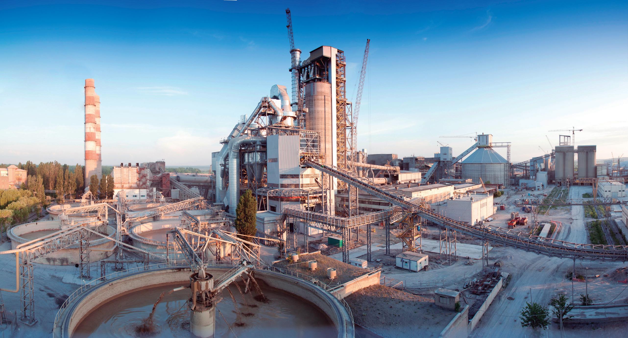


+ 30 short talk slots places technology suppliers

Be part of the only platform in Latin America and the Caribbean dedicated to the exchange of knowledge, success stories and best practices.

+ 39 presentations from industry and technology suppliers
7 key-note speakers

80 booths of more than 60 commercial firms present at the trade show
Technical visit to a cement production plant
This registration fee includes:

Cancellations made before Friday, July 12, 2024, a 20% charge will be applied to the total cost of registration, booth and/or sponsorship.
For cancellations made after Friday, July 12, 2024 and before Friday, August 18, 2024, a 50% charge will be applied to the total cost of registration, booth and/or sponsorship.


For cancellations made after Friday, August 18, 2024, a 100% charge will be applied to the total cost of the registration, booth and/or sponsorship.
f Benefits: This solution can improve customer loyalty and significantly reduce the need for manual inquiries. It also provides better opportunities to intervene quickly if necessary, based on up-to-date information for each delivery.
Various use cases for mobile applications in bulk goods logistics have been discussed. It is now important to question how this can work in practice, without having to maintain and manage a large number of individual solutions and provide them with individual interfaces.
The answer is to use a mobile framework like with the mobile applications from Axians IAS. This means controlling a wide variety of mobile apps via a common backend platform, into which other customer cases can also be flexibly integrated. Full integration with central logistics workflow solutions (such as Axians VAS Cloud Logistics) and connections to plant logistics solutions (such as Axians VAS Yard Management) guarantees, that the apps are provided with the exact data required for the respective area of application by the backend and that data can also be transferred from the app to other workflow systems via these interfaces.
With such a solution, the simultaneous use of mobile apps for a wide range of use cases becomes manageable and the full potential of the apps can be utilised. Of course, this requires a competent partner who, like Axians IAS, has the appropriate framework for mobile solutions as well as a professional innovation and implementation team. This is how mobile apps can really help to gain a competitive advantage.
Many examples of the use of mobile apps in bulk goods logistics have been explained in the previous sections. But this is of course only a selection of the entire service portfolio. Listed below are a few more areas of application for mobile app solutions that are already available at Axians IAS:
f Safety in the loading plant and on the construction site: The Security App can be used to monitor the correct behaviour of truck drivers, especially with regard to protective equipment, to ensure compliance with safety regulations and to ensure that protective equipment is used and worn correctly.
f Lot tracking: The app enables the precise tracking of the material in a delivery directly to the silo of origin, including detailed information on the composition, which is supplemented by laboratory information such as the degree of whiteness and viscosity of the material and linked to the electronic delivery bill.
f Quality information: To ensure the quality of a delivery, it is necessary to scan bags or delivery bills in order to record and document the corresponding proof of quality, such as the
documentation of material samples, using the app.
f Truck sealing: The app is used by suppliers, recipients and customers to scan the seals on the truck’s loading opening. This provides proof that the load has not been tampered with during transportation.
f Truck cleanliness check: The ‘Check 4 Truck Cleanliness’ app includes checking and documenting the cleanliness of the truck to ensure and prove that the delivery has not been contaminated by a dirty truck.
f Train loading: The Train Loading App is a tool for recording, sequencing and assigning wagons when loading bulk goods by rail.
f Hazardous goods check: The Hazardous Goods Check app is used to verifiably manage safety documents for deliveries. It also provides important information and guidelines for implementing the necessary safety measures.
Mobile apps for use on tablets and smartphones are becoming increasingly important in industrial applications such as bulk goods logistics, enabling the flexible and optimised processing of a wide range of tasks outside of an office environment. Time savings, maximum transparency, greater security and a paperless workflow through the use of mobile apps lead to efficiency gains and improved sustainability. Users in many areas including customers, suppliers, carriers, truck drivers and goods recipients can benefit from the use of mobile applications. And the potential applications and demand in the market will certainly continue to grow significantly.
However, a professional overarching mobile framework and integration with leading logistics systems is a prerequisite for optimal use in bulk goods logistics
For optimal deployment, where seamless integration and professionalism are key, the right technological support can make all the difference in avoiding fragmented, isolated solutions with inconsistent data. An experienced partner with a comprehensive mobile framework and mobile applications can help overcome such fragmentation and bring consistency to the data flow. Axians IAS, with its years of experience and successful applications in the digitalisation of bulk logistics, can play a key role in this context by enabling companies to design their processes in an efficient and future-oriented way, even with customised mobile app solutions.
Reiner Bachthaler has roots in industrial software-based automatisation projects and long-term experience in Software Product Management. He is a Senior Product Manager at Axians Industrial Applications GmbH.

GAMBAROTTA GSCHWENDT reviews different types of conveyors used to transport clinker for the cement production process.
Clinker is the ‘blood’ of the cement production process, and from the kiln to the cement mill, it must be carried uninterrupted and in large volumes. In all cement plants there are three main process stages: f Transportation from the cooler at the kiln exit, to the top of the clinker silos to be stored.
f Extraction under the silos and transportation to the cement mill to ground.
f Distribution to multiple silos.
This article will focus on the first two stages. The first will explore the different types of conveyors which can be used for transporting clinker. This will then be followed by a discussion of the different requirements that each of these process areas require from conveying equipment, focussing on the best selection criteria for this machine.
Nowadays multipurpose machines have become a must-have in modern plants, since they lead to a reduction in production costs. For the transportation of a hot, abrasive material such as clinker, different types of conveyors have been developed. These conveyors are very versatile, as they can change the conveying direction from horizontal to inclined and, if necessary, back to horizontal. Therefore, they can be treated as ‘multipurpose machines’ as, in many instances, one of these machines can perform the functions of several conveying machines.
Given the low conveying speed of these machines, the wearing rate of all moving parts is kept down to a minimum. This leads to a much longer working life of GAMBAROTTA conveying systems.
GAMBAROTTA GSCHWENDT has five main clinker apron conveyors, which can be divided into two types:
Type 1: Conveyors with intermediate discharge
These machines transport clinker, and discharge it into multiple outlets, which can be either movable or fixed. Typically, these conveyors are used to distribute clinker over multiple silos.
Type 2: Conveyors without intermediate discharge
These machines convey clinker from one or more loading points to a single discharge point. Three kinds of clinker conveyor belong to this type.
Used to transport clinker on horizontal or slightly inclined slopes (generally up to 45°), apron conveyors are largely employed in modern plants. They often have one or more inlet points, and are loaded directly by an upstream machine or fed through a helmet-gate placed at the bottom of a silo. The key element of these conveyors are the pans, which are designed to ensure the continuity of the metallic belt. When the inclination of the conveyor exceeds the dynamic angle of repose of the transported material, a transverse ledge may be installed on the pans, to prevent backsliding of the material.
GAMBAROTTA GSCHWENDT pans are fixed at the bottom to double chains with flat links and a fixed bush and form a continuous metallic band designed to carry the material. One out of four or five pans is supported by two hardened steel rollers with life lubricated bearings. The pans roll on rails, hence minimising the power absorbed by these machines, which is energy-saving. The height of the pan sides can be suitably adjusted to match the material layer height, so that at low speeds the conveying capacities can be remarkably high (i.e. some GAMBAROTTA GSCHWENDT clinker conveyors currently in operation transport 2000 tph at a speed of 0.3 m/s). The company’s chains are driven by two drive wheels, equipped with replaceable toothed sectors, made of induction-hardened alloyed steel.
Designed to convey clinker on very steep slopes, generally between 40 – 60°, box conveyors are similar to pan conveyors, except that the material is transported into boxes fixed at the bottom to flat-link chains.
GAMBAROTTA GSCHWENDT boxes incline towards the transport direction, in order to increase their capacity on slopes. Every second box is supported by two hardened steel rollers, and overlaps the following box to prevent material from escaping between two adjacent boxes when loaded into the conveyor. Compared to pan conveyors, box conveyors can provide a more efficient transportation at high inclination angles, providing often the same transport capacity with a lower machine width. On the other hand, the vertical dimensions of a box conveyor may be larger than an equivalent pan conveyor. Usual transport capacities range from 90 – 800 tph.
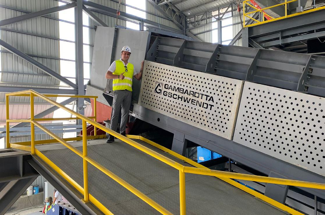
GAMBAROTTA GSCHWENDT bucket conveyors have been specifically developed to be installed under the
clinker cooler at the kiln exit. These bucket conveyors carry the material into buckets, shaped to optimise their capacity at inclination angles between 40 – 65˚. The chains are fixed at buckets sides and support rollers are mounted on every bucket and are integrated into the chain. This GAMBAROTTA machine is designed to transport hot material at high inclination angles with the minimum possible vertical dimensions. The chains fixed at the sides save vertical space (which can be a relevant cost-saving feature, should the conveyor be installed under the clinker cooler); the position of the chains protects them and the rollers from the heat. The rollers can be accessed and replaced, if necessary, without disassembling any component, thus minimising the shut-down time. Usual capacities range from 100 – 1000 tph.
If the conveyor is well built, there will be no material leakage between the pans (or the boxes); however, some dust will remain attached to the conveyor surface and will detach near the drive and idle wheels. This clinker powder will start to increase at the machine bottom, and will need to be removed.
There are essentially three ways to remove the dust from the machine:
For pan conveyors only
f Manual cleaning: Stop the machine and remove the dust from the bottom.
f Automatic cleaning over the entire conveyor’s length by gravity scrapers (possible only for inclination angles below 30˚). A cleaning scraper is hinged to the pan assembly at regular intervals, for example every 20 m or more. The scraper lays on the pans on the transport side, buried in the material flow. When the scraper turns around the drive wheels, the scraper touches the machine bottom and collects the dust, carrying it towards the return station. When the scraper turns around the return wheels, it reverses dust from the machine bottom back into the main upper flow.
For all clinker conveyor types
f GAMBAROTTA GSCHWENDT’s automatic cleaning system through a recycling scraper conveyor: this is the most efficient way to clean a clinker conveyor, and it is applicable to all conveyor types. A C-shaped scraper conveyor collects the dust from below the machine and recycles it into the main clinker flow. A less expensive option is the installation of a straight scraper conveyor under the last 5 m of the conveyor before the drive station. The scraper conveyor collects the dust falling from the reversed pans on the return side and pours it into the main discharge chute.
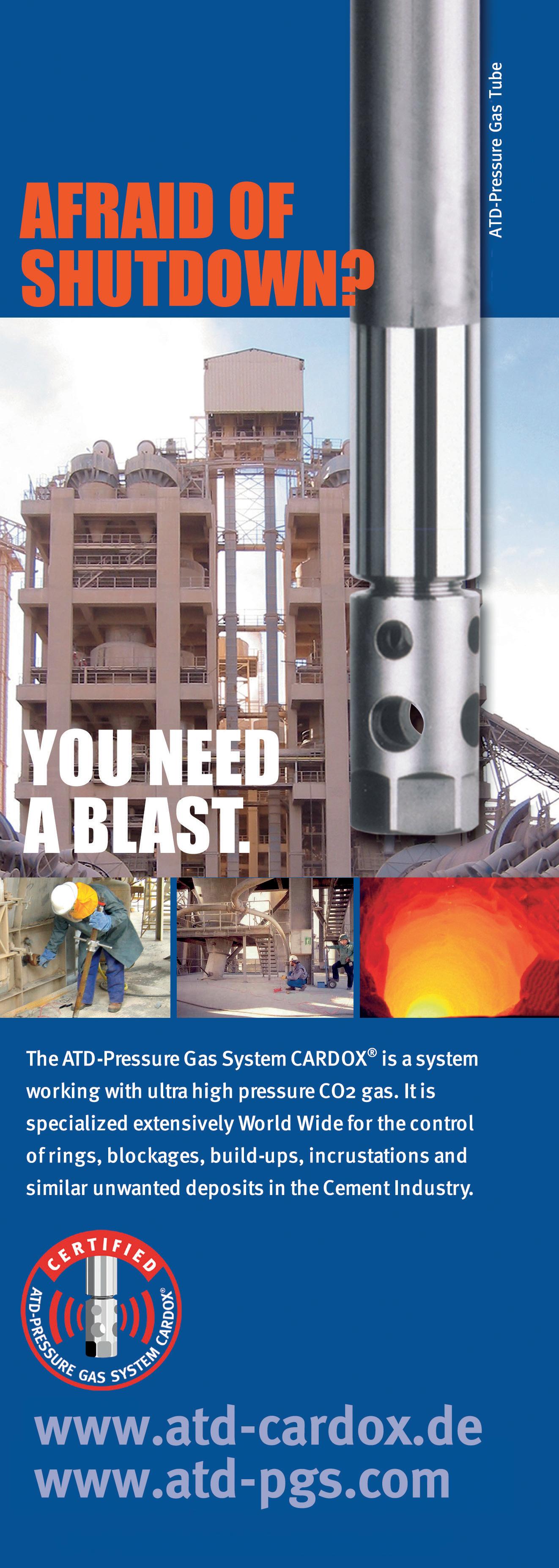
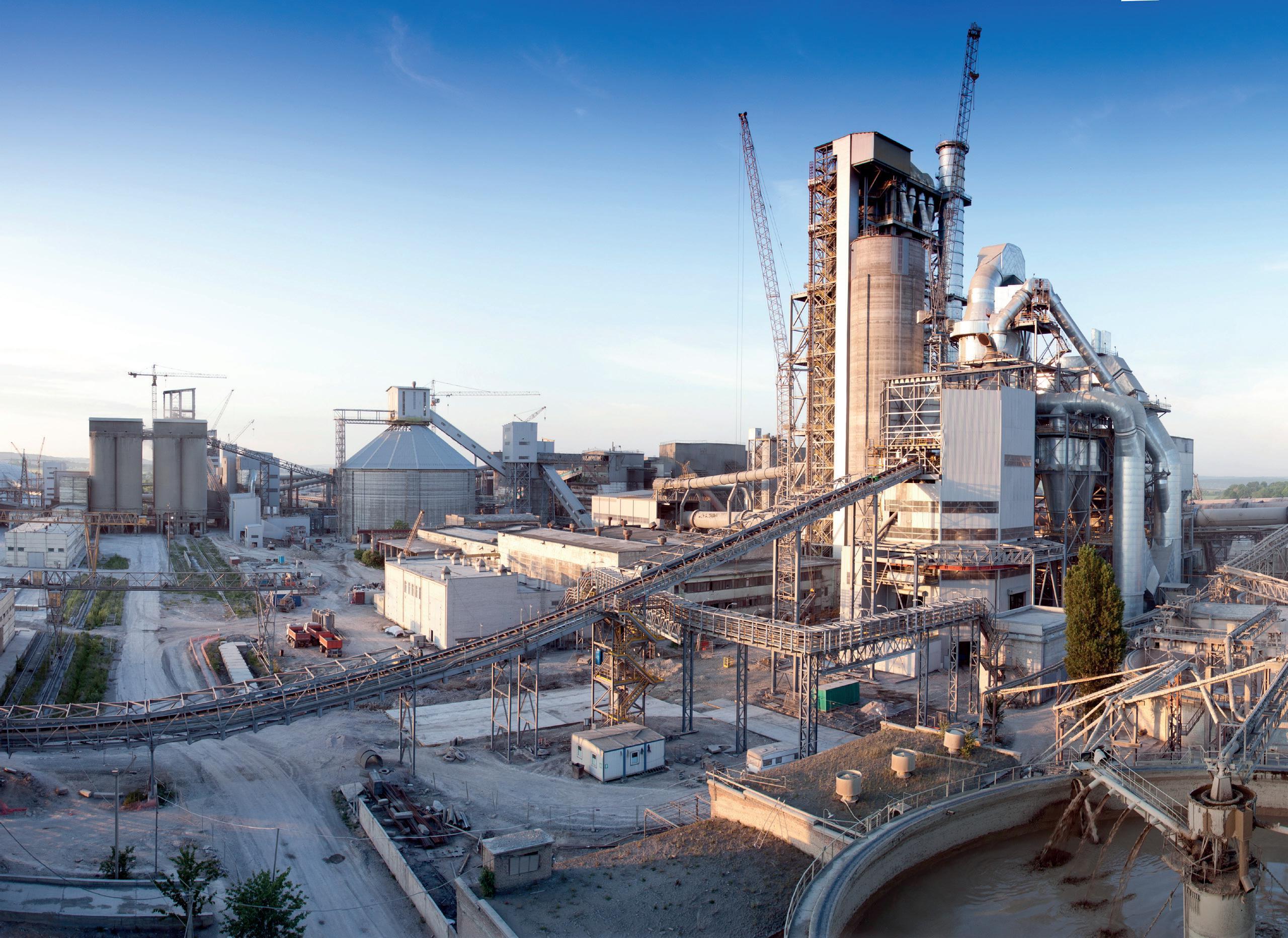
• International cement news
• Regional reports
• Market analysis
• Event previews and reviews
• In-depth technical articles
• In-depth regional analysis by key players in the industry
• Comprehensive technical reviews on all aspects of cement production, from the quarry face to despatch


Dracyon considers the common weaknesses of air cannons, and explains
how they can be overcome.
Accepting widely held assumptions is a great hindrance to productivity. Breakthroughs often occur when assumptions are challenged. This is the case for air cannon technology.
Many plants assume their air cannons are technologically advanced. The reality is that most air cannons were designed around the turn of the century and have experienced little progress since then. Not many people would consider a television designed in 2007 to be advanced.
A plant’s air cannons are also assumed to be effective. Yet most plants provide supplemental cleaning services, such as high-pressure water washing. If a lawn care service required regular supplementation, it would not be considered effective.
A final assumption made is that air cannons are reliable. However, many air cannons are out of order and others require a steady stream of replacement parts. A car requiring the same amount of attention would not be driven.
Dracyon challenged these assumptions and produced an air cannon that is truly advanced,
effective, and reliable. This breakthrough enables plants to save money through reduced maintenance costs and increased productivity. Yesterday’s air cannon will not solve today’s challenges.
What makes a golf swing powerful? At first glance, some might say ‘arm strength’. Arm strength is important, but the torque generated by the midsection is far more important.
Something similar has happened in the air cannon industry. When asked what the most important factor for air cannon cleaning is, many answer ‘peak force’. Like the golf swing analogy, peak force is important but another factor is far more important: momentum and kinetic energy.
The difference described above is crucial because it affects the design of air cannons. If peak force truly is the answer, the best air cannons will be determined by quick release valves. If momentum and kinetic energy are the answer, then the best air cannon will be defined by volume and nozzle design.
Volume is related to kinetic energy (KE=1/2mv2) and momentum (p=mv). When it comes to air cannons, the easiest way to increase volume is to increase the size of the reservoir tank. This is, perhaps, the most recognisable feature of Dracyon’s Big Blue air cannon.
Many plants are supplied with 70 l or 150 l air cannons. By increasing the volume to 300 l, the Big Blue air cannon more than doubles and (nearly) triples the kinetic energy and momentum compared to its competitors. Without volume the cleaning area is limited.
Velocity is also related to kinetic energy and momentum but with one important difference. Velocity is exponentially related to kinetic energy.
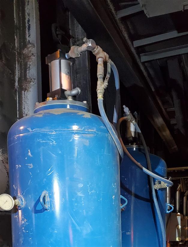
A doubling of velocity will yield a quadrupling of kinetic energy.
The best way to increase velocity is through the design of the nozzle. Air cannons have typically employed a fan jet nozzle designed to produce a wide blast of air over the greatest possible surface area. What it gains in wide surface area, it sacrifices in velocity. A wide blast will accomplish nothing if it does not have the power to move the material. In today’s plants, cleaning only 1 m in front of an air cannon is not enough.
Instead of focusing on surface area, Dracyon’s nozzle is designed to move material. Firstly, it is larger (6 in. versus 4 in.). The larger nozzle generates more air (or volume), therefore, cleans at the time of discharge. Secondly, it increases velocity by choking the outlet opening. This is similar to using a thumb to increase velocity from the garden hose. The result of these design features is simple. A large volume of air is discharged with very high velocity. A nozzle, in other words, that moves material.
With greater kinetic energy and velocity, the Big Blue air cannon moves more material than other air cannons. Plants can generate more cleaning power with fewer air cannons, as Table 1 illustrates.
This technological advancement is a direct result of challenging the prevailing assumption that peak force was the most important factor for air cannon cleaning.
Poorly designed air cannons are the inevitable consequence of having low expectations. Many plants still believe that their air cannons are effective despite the need for regular manual cleaning services. On the one hand, this is reasonable; it would be unfair to expect small air cannons with fan jet nozzles to not require additional manual cleaning. However, this does not have to be accepted as the standard; an effective air cannon should remove the need for manual cleaning. Moreover, it is important to note that manual cleaning is a safety risk.
One reason plants are resigned to manual cleaning is because they underestimate its detrimental impact. Manual cleaning, especially high-pressure water washing should be avoided because:
f It is unsafe. The most common injury is long term damage to the worker’s back and wrist. More acute injuries, such as burns and even sudden death, are also possible.
This table does not consider the impact of increased velocity.
f It is expensive. The introduction of false air into the process wastes fuel. One cement plant estimated that a 1 in. diameter hole in the tower cost US$50/hr. Increasing to scale, an open access door will cost US$3200/hr in wasted fuel costs.
f It is destructive. High pressure water washing destroys the refractory. Not only does this result
in more frequent replacements of the refractory, it also scarifies efficiency due to increased thermal loss.
f It is counterproductive. Regular high-pressure water washing indicates an inefficient tower. While the cleaning method is ‘necessary’ to eliminate buildup, it makes matters worse by introducing moisture into the process. This, in turn, worsens buildup and mandates more frequent manual cleaning.
It is not an exaggeration to suggest that frequent manual cleaning is costing cement plants millions of dollars per year while placing workers’ safety in jeopardy.
What the industry needs most is raised expectations concerning air cannon technology. If a plant spends hours every week manually cleaning, their air cannon installation should be deemed ineffective. Air cannons should be judged by their ability to eliminate supplemental cleaning services.
With the increased technology offered by Big Blue, Dracyon has high expectations for its air cannon installation. An effective installation in the riser duct, for example, must:
f Clean the entire wall.
f Reduce high-pressure water washing by at least 90%.
f Extend refractory life replacement to every three years.
The technology exists to save millions by reducing manual cleaning services. Air cannons should be trusted to do this, just as a lawn care service is expected to keep all your grass trimmed. It is time for cement plants to demand a better cleaning performance.
Even if an air cannon is less effective, it is still better to have one than none at all. Sadly, many plants do not have any because the ones they have are not functioning. In other cases, plants must regularly purchase spare parts to keep their air cannons operational. The industry has accepted this standard for too long. Just as expectations for performance should change so, too, must expectations for reliability.
Many of the problems associated with air cannon failure are entirely avoidable. They often stem from poor installation practices. The most common of which are:
f Installing the air cannon too close to the application. This practice is often related to the notion that peak force is the
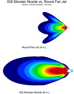
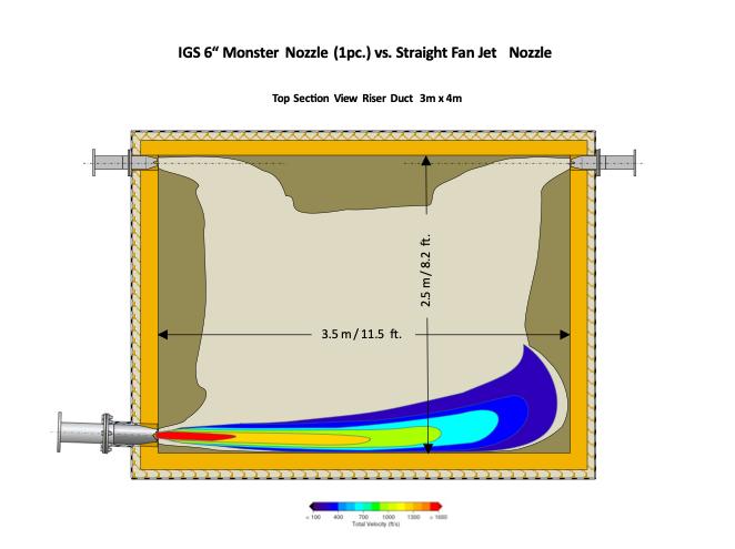
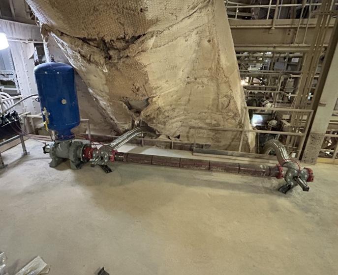
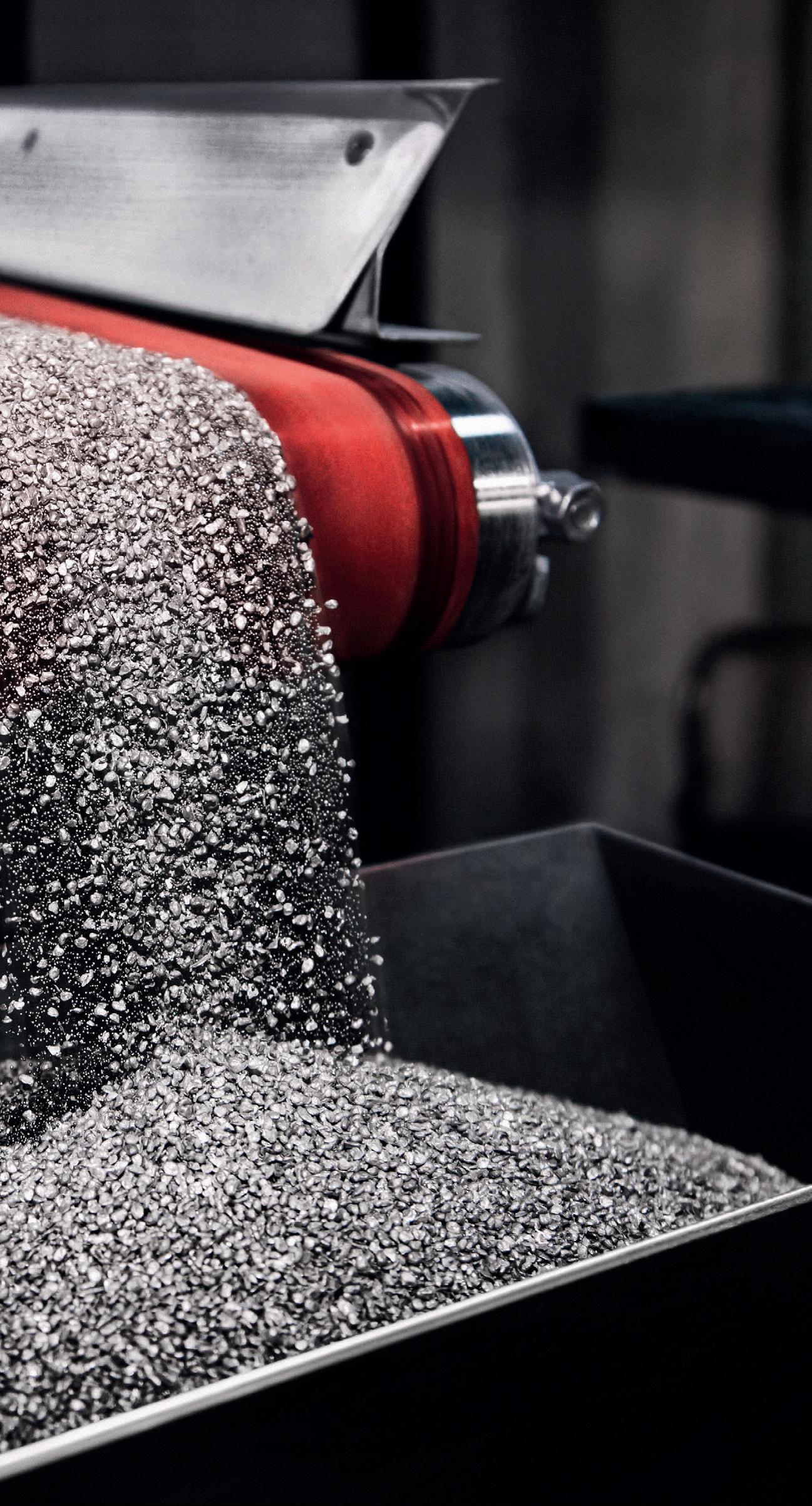

www.solids-recycling-technik.de/en/tickets
most important factor for cleaning (peak force is significantly reduced in long pipe runs). When air cannons are close to the application, they are exposed to the heat, which, in turn negatively affects the air cannon’s internals.
f Installing the air cannon at a negative angle. One of the most irresponsible practices is installing the air cannon facing upward (even slightly). That guarantees that the material from the process will eventually enter the air cannon and cause premature failure. This, too, is often associated with a desire to maintain peak force and avoid long pipe runs.
f Installing the air cannon in an inaccessible location. Air cannon maintenance often require slight adjustments that can be performed online. If the air cannon is inaccessible, however, maintenance cannot be performed, and cleaning is lost.
When air cannons do not work, buildup, manual cleaning, and fuel costs increase. Unreliable air cannons cost plants millions of dollars every year.
All air cannons will fail eventually. The key to reliability is to reduce premature failure as far as possible and provide online maintenance when needed. These objectives can be accomplished by doing the opposite of what is described above. A reliable air cannon must be:
f Installed at a safe distance from the process. By reducing exposure to the heat, premature failure is avoided.
f Installed in an upright position. By reducing process intrusion, the air cannon internals are protected from corrosion.
f Installed in an accessible location. By ensuring access, many small problems can be solved while online.
One of the best ways to ensure these objectives is through longer pipe runs as shown in Figure 3.
It does not matter how advanced an air cannon is if it is not working. The industry has accepted frequent replacement and spare parts for too long. With a few adjustments to installation practices, air cannons should be backed by a 10-year warranty and 3-year nozzle warranty. Dracyon is willing to stand by that guarantee because customers deserve better.
The old assumptions concerning air cannon technology have been weighed, measured, and found wanting. It is past the time for the industry to rethink what it means for an air cannon to be advanced, effective, and reliable. Through reduced maintenance and increased productivity, plants will save millions of dollars annually. Only today’s air cannon will solve today’s challenges.


Invertek Drives explains how variable frequency drives can help the cement industry to become more energy efficient.
The cement and construction industries are the backbone of modern global infrastructure, shaping our cities, roads, and homes.
These sectors, while vital, are also known for their significant energy consumption and environmental impact. Behind the scenes, a technology called variable frequency
drives (VFDs) is quietly revolutionising these industries, driving efficiency, reducing costs, and promoting sustainability.
VFDs, in essence, are sophisticated electronic devices that control the speed and torque of electric motors.
By dynamically adjusting the frequency of the electrical power supplied to the motor, VFDs enable precise matching of the motor’s output to the specific demands of the application. This not only optimises performance but also significantly reduces energy consumption compared to traditional motor control methods.
Kes Beech, Technical Manager at Invertek Drives, explains: “VFDs are the unsung heroes of the cement and construction industries.
They are instrumental in reducing energy consumption and carbon emissions, extending equipment lifespan, and improving overall operational efficiency.”
In Europe, the European Union’s Industrial Emissions Directive (IED) sets stringent limits on emissions of pollutants such as nitrogen oxides (NOx), sulfur dioxide (SO2), and particulate matter (PM) from cement plants. The IED also encourages the use of Best Available Techniques (BAT) to minimise environmental impact, and VFDs are recognised as a BAT for improving energy efficiency and reducing emissions in various processes.
In the United Kingdom, the Climate Change Act sets ambitious targets for reducing greenhouse gas emissions.
The construction sector, being a significant contributor to emissions, is under pressure to adopt energy-efficient technologies and practices.
VFDs are playing a crucial role in helping construction companies meet these targets by optimising energy use in various applications, from powering cranes and hoists to controlling HVAC systems in buildings.
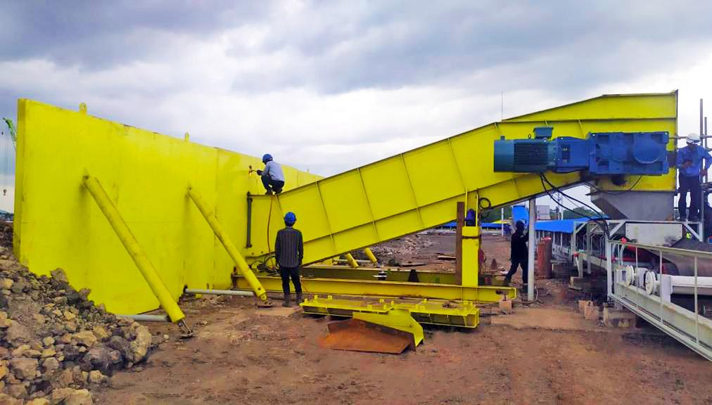

Meanwhile, in the United States, the Environmental Protection Agency (EPA) regulates emissions from cement plants under the Clean Air Act. The EPA’s New Source Performance Standards (NSPS) for Portland Cement Manufacturing set limits on emissions of PM, SO2, and NOx. VFDs can help cement plants comply with these standards by improving the efficiency of motors and fans, reducing emissions, and conserving energy.
Additionally, regional initiatives like the Regional Greenhouse Gas Initiative (RGGI) in the Northeastern United States are incentivising the adoption of energy-efficient technologies like VFDs to reduce carbon emissions.
These regulations, while imposing stricter requirements on the
cement and construction industries, are driving the adoption of VFDs as a means to achieve compliance and improve sustainability.
Cement plants and construction companies are increasingly recognising the multiple benefits of VFDs, including energy savings, reduced emissions, improved equipment lifespan, and enhanced operational efficiency.
Government incentives and subsidies for energy-efficient technologies are further encouraging the adoption of VFDs. For example, the UK’s Enhanced Capital Allowances (ECA) scheme provides tax relief for investments in energy-saving equipment, including VFDs.
As the world moves towards a more sustainable future, the role of VFDs in the cement and construction industries is set to become even more critical. With stricter regulations on emissions and energy use, VFDs will be instrumental in helping these industries reduce their environmental impact and transition towards cleaner and more efficient operations.
Advancements in VFD technology, such as the integration of artificial intelligence and machine learning, are opening up new possibilities for optimising energy use and further reducing emissions.
VFDs equipped with smart sensors and data analytics capabilities can continuously monitor and adjust motor performance in real-time, ensuring optimal efficiency and minimising energy waste.
The cement production process involves numerous stages, from crushing and grinding raw materials to kiln operation and final product handling. Each stage presents unique challenges that VFDs are well-equipped to address.
Take conveyor systems, for instance. They are the arteries of a cement plant, transporting raw materials, clinker, and finished cement. VFDs ensure that conveyors operate at the optimal speed, preventing bottlenecks, minimising wear and tear, and reducing energy waste. By matching the conveyor speed to the actual material flow, VFDs can save up to 30% of the energy consumed by conventional motor starters.
Crushers and mills, the heavy-duty workhorses of cement production, demand immense power to pulverise raw materials. VFDs provide precise control during startup and operation, reducing mechanical stress, improving energy efficiency, and extending equipment lifespan. This translates to substantial cost savings for cement producers.
VFDs, such as Invertek Drives Optidrives, also play a vital role in material handling applications,
optimising the operation of cranes, hoists, and other equipment used to move heavy loads. They ensure safe and efficient operation, minimising the risk of accidents and equipment damage.
In pumping applications, VFDs maintain consistent flow rates, pressure, and temperature, critical for ensuring product quality and preventing equipment damage. This is particularly important in water pumping systems used for cooling and cleaning in cement plants.
Moreover, VFDs are indispensable for controlling fans and ventilation systems. By precisely adjusting airflow, VFDs optimise energy use and maintain a safe and comfortable working environment for plant personnel.
The real-world impact of VFDs is undeniable. An Indonesian plant, for example, achieved a remarkable 20% reduction in energy consumption and a 15% increase in productivity by deploying Invertek’s Optidrive P2 VFDs on its material handling system. The drives’ high performance, robust design, and ease of use proved invaluable in the harsh conditions of the cement industry.
As the construction industry grapples with the growing demand for sustainable building practices, VFDs are emerging as a key enabler of energy-efficient and environmentally friendly construction.
From powering concrete mixers and cranes to controlling HVAC systems in buildings, VFDs are reducing energy consumption and carbon emissions throughout the construction lifecycle.
The latest generation of VFDs, such as Invertek’s Optidrive E3, offers advanced features like integrated energy monitoring, predictive maintenance capabilities, and enhanced communication protocols for seamless integration into plant automation systems. These innovations are further empowering cement producers and construction companies to optimise their processes, reduce costs, and build a more sustainable future.
It is true to say that VFDs are the unsung heroes that are quietly transforming the cement and construction industries. Their ability to optimise motor control, reduce energy consumption, and extend equipment lifespan is invaluable in a world where resource efficiency and sustainability are paramount.
As VFD technology continues to evolve, even greater advancements in energy savings, productivity, and environmental benefits can be expected. VFDs are not merely a technological innovation, they are a catalyst for a greener and more efficient future in the cement and construction sectors.
ABC
www.abc.org.uk
AFCM TS&E 2024 26afcm-tse.com
Alimak www.alimak.com
ATD Abbausysteme GmbH www.atd-cardox.de / www.atd-pgs.com
BOLDROCCHI
www.boldrocchigroup.com
Chart Industries www.chartindustries.com
Christian Pfeiffer christianpfeiffer.com
DCL
www.dclinc.com
Dracyon Corp. www.drayconcorp.com
EnviroTech Athens www.worldcement.com/envirotech2025
Euromecc www.euromecc.com
FICEM Technical Congress 2024 www.congressotecnico2024.ficem.org
Geometrica www.geometrica.com
HEKO www.heko.com
IKN www.ikn.eu
Lubrication Engineers
www.LElubricants.com
MAAG
www.maaggear.com
Maerz
www.maerz.com
N+P
www.npgroup.com
PROMECON
www.promecon.com
PSCL
www.pscl.com
Scheuch www.scheuchna.com
Silobau Thorwesten www.thorwesten.com
SOLIDS Dortmund www.solids-recycling-technik.de
stela Laxhuber GmbH www.stela.de
TÜRKÇIMENTO teknikseminer.com.tr
Van Aalst Bulk Handling www.vanaalstbulkhandling.com
Vortex Valves www.vortexglobal.com
World Cement www.worldcement.com


As the innovative and passionate world leader, we have been setting standards in the design and construction of kilns for the lime industry for more than 60 years. Our wide choice of kiln types combined with our process know-how and advanced technology provides you with all options for future-proof investments in new kilns or upgrading existing lime plants.
maerz.com