


MAGAZINE | SEPTEMBER 2023
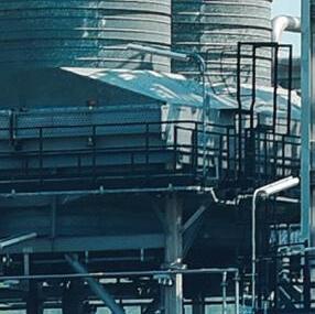
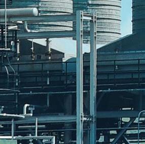
Euromel® Melamine The state-of-the-art HP technology


Euromel® Melamine - the leading and most advanced technology for the production of high-quality melamine used in wood-based products, laminates, moulding compounds and fire-extinguishing foams in the last 40 years.


Delivers high purity, high consistency melamine with total zero pollution (TZP) with extremely lower energy consumption using 30% lesser steam import and 20% lower fuel utilisation than the closest competitor.
Euromel® Melamine Process is now used in 28 plants worldwide, accounting for more than 8 million tonnes of melamine produced cumulatively, making it the most traded and widely used melamine worldwide.

10

The Green Light For Blue Ammonia
Richard Ewing, Profercy Nitrogen, United Kingdom, explains how the low-carbon ammonia revolution is gathering pace as established players and new names look to take advantage of the development of cutting-edge technologies.
16 The Many Faces Of Ammonia
Kevin Rouwenhorst, Proton Ventures, the Netherlands, discusses the many applications for green ammonia, from the fertilizer sector to use as a hydrogen carrier.
22 A Whole New World
Ezio Pasqualon and Manuel Crotta, Maire Tecnimont, Italy, consider how the metaverse is being integrated into fertilizer plant operations.
27 Exploring Bimetallic Tubing
Tony Bugno, Alleima, USA, discusses how corrosion resistance can be maximised in nitric acid plants.
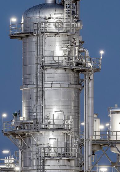
32 Getting The Big Picture With Vertical Pumps
Marwan Karaki, Weir Minerals, USA, outlines the considerations to be made before choosing a vertical chemical pump, and explains the importance of proper selection, installation and maintenance.
36 Reaching Full Potential
Christen Mancini, Hydro Inc., USA, discusses how pump systems can be optimised to reach operational excellence and reduce environmental impact.
41 Playing By The Rules
Brian Rudary, Swagelok Company, USA, discusses the importance of following design practices in order to ensure more effective maintenance and smoother running of critical operations in fertilizer processing plants.
47 Scaling Down
Rajesh Raitani and Steven Paulson, Nalco, USA, provide an overview of phosphoric acid heat exchanger scaling and its impact on productivity in the fertilizer industry.
51
Decarbonisation Acceleration


Igor Makarenko and Gerald Marintsch, Solex Thermal Science, Canada, explore the energy upcycling opportunities available to today’s fertilizer producers.
54
Choosing The Right Additive
Jacco Korver, INSTRAL B.V, the Netherlands, discusses the advantages and disadvantages of numerous additives used by fertilizer manufacturers.
59
Addressing The Root Cause

Ron Porter and Brad Schick, Veolia Water Technologies and Solutions, and Tyler McDowell, Nutrien, Canada, explain how water clarification optimisation can boost plant reliability and reduce water footprints.
63
More Than A Nutrient!
Aviv Bar Tal, OCI Global, the Netherlands, examines the role that nitrogen fertilizers are playing in the global food crisis.
67 Upgrading Urea Technology


Kazuki Kamikubo, TOYO Engineering, Japan, discusses the significance of new urea technologies and outlines the benefits of lowered synthesis pressure for producers.
73 Seeking Synergy

Robert van Spingelen and Chris Thornton, European Sustainable Phosphorus Platform, Belgium, explain how phosphorus recycling could result in a synergy of mineral and organic carbon fertilizers.
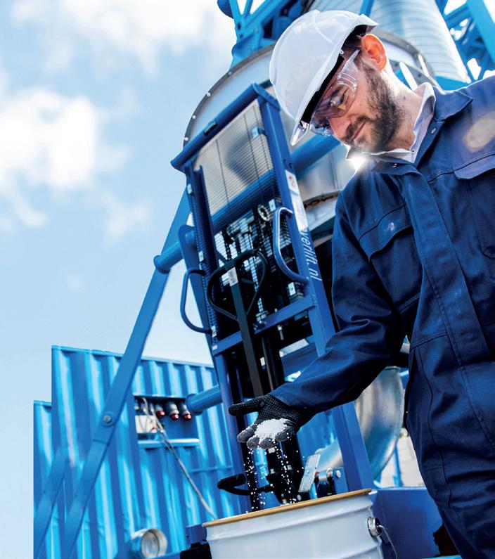
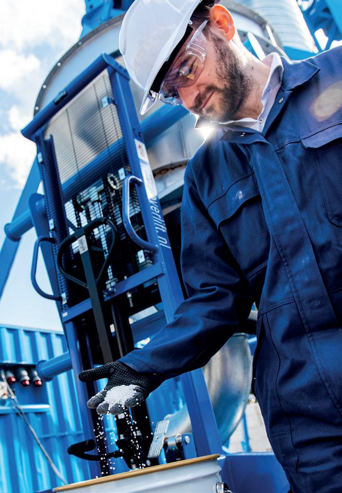
Over the past decades Kreber has built an impressive track record in prilling equipment. With the company’s innovative Kreber Pilot Facility, new products such as compounded fertilizers can be validated and optimised before scaling up. The facility is capable of generating industrial representative samples of new fertlizer products whilst acquiring key data for prilling process optimisation necessary for scaling up production.
ON THE COVER
Comment
News
03
05
follow @WorldFertilizer like World Fertilizer join World Fertilizer Copyright© Palladian Publications Ltd 2023. All rights reserved. No part of this publication may be reproduced, stored in a retrieval system, or transmitted in any form or by any means, electronic, mechanical, photocopying, recording or otherwise, without the prior permission of the copyright owner. All views expressed in this journal are those of the respective contributors and are not necessarily the opinions of the publisher, neither does the publisher endorse any of the claims made in the advertisements. Printed in the UK. CBP019982
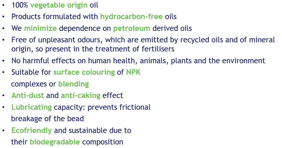
MAGAZINE SEPTEMBER 2023 Jacco Korver, INSTRAL B.V, the Netherlands, discusses the advantages and disadvantages of numerous additives used by fertilizer manufacturers. F ertilizer manufacturers strive to produce the best possible quality fertilizers in the most efficient and responsible way. In order to achieve this, additives have to be used to help processes go more smoothly and to ensure that the fertilizers can be stored, shipped and used without problems. Examples of such additives are: n Binders and granulation additives. n Coatings. Colouring agents. n Solubilising agents. Others such as talcum powders or clays. Besides continuously wanting to improve production and product quality, many factors encourage fertilizer be changes in legislations, composition and prices of raw materials and in the availability and prices of the additives themselves. Within the EU, the biostimulant and fertilizing products regulation (EU) 2019/1009 came into force in July 2022, prohibiting the use of non-biodegradable ingredients in agrochemicals. This has pushed many fertilizer manufacturers to look for bio-based alternatives. Coatings For solid fertilizers, coatings are used for the following To reduce caking and lumping of the fertilizers. To reduce moisture uptake of the fertilizers. To depress the liberation of dust during the handling of the fertilizers. Anticaking coatings prone to caking. To inhibit this, anticaking coatings and by manufacturers. The coatings can be water-based, but the paraffins. When properly selected and blended in CHOOSING THE RIGHT ADDITIVE 54 CONTENTS
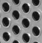
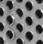
Pop-A-Plug ® Tube Plugs


ASME PCC-2 Compliant Heat Exchanger Tube Plugging System


Trusted by fertilizer plants around the world as their go-to solution for heat exchanger tube leaks, Pop-A-Plug Tube Plugs from CurtissWright are engineered for optimal performance throughout the life cycle of equipment. Controlled hydraulic installation eliminates welding and time-consuming pre-/post-weld heat treatments that can cause damage to tubes, tube sheet ligaments, and joints.

• No Welding Required
• Pressure Ratings Up to 7000 PsiG (483 BarG)


• Simple Hydraulic Installation


• Helium Leak Tight Seal to 1 x 10⁻¹⁰ cc/sec


• 100% Lot Tested to Ensure Unmatched Quality


• ASME PCC-2 Recommended Tube Plugging Repair Methods


• Wide Range of Sizes& ASME/ASTM Certified Materials Available


877.383.1029 l est-sales@curtisswright.com l cw-estgroup.com/wf-23

CONTACT US
MANAGING EDITOR
James Little james.little@palladianpublications.com
SENIOR EDITOR
Callum O’Reilly callum.oreilly@palladianpublications.com
DEPUTY EDITOR
Emily Thomas emily.thomas@palladianpublications.com
EDITORIAL ASSISTANT
Jack Roscoe jack.roscoe@palladianpublications.com
SALES DIRECTOR
Rod Hardy rod.hardy@palladianpublications.com
SALES MANAGER
Ryan Freeman ryan.freeman@palladianpublications.com
PRODUCTION
Kate Wilkerson kate.wilkerson@palladianpublications.com
ADMINISTRATION MANAGER
Laura White laura.white@palladianpublications.com
DIGITAL ADMINISTRATOR
Leah Jones leah.jones@palladianpublications.com
EVENTS MANAGER
Louise Cameron louise.cameron@palladianpublications.com
DIGITAL EVENTS COORDINATOR
Merili Jurivete merili.jurivete@palladianpublications.com
COMMENT
EMILY THOMAS, DEPUTY EDITOR

Sunday 20 th August saw England reach its first football World Cup final since 1966, with the country’s women’s team, the Lionesses, battling to take home the trophy. While the team gave their best efforts, it simply wasn’t to be for England, as the match saw Spain crowned World Cup champions.
This year’s tournament reached record viewership figures, 1 and an outpouring of support and appreciation for women’s football has been felt across the world. Against this backdrop, it is easy to overlook just how far the beautiful game has come over the years; for instance, the last time England were this close to World Cup victory, women were banned from playing the sport at FA-affiliated football grounds. The ban came at the turn of the 1920s, as Dick, Kerr Ladies F.C, a factory team from Preston, gained popularity to rival male football teams. The FA issued the ban, declaring: “The game of football is quite unsuitable for females and ought not to be encouraged.” 2
Astoundingly, the ban stood for 50 years, having only been rescinded in 1970. Thankfully, women’s football has since had a significant resurgence; despite falling at the final hurdle, there is no doubt that the Lionesses have been a source of inspiration for girls across England, with the team proudly representing women in male-dominated industries, and rallying for equal opportunities within the sport. Off the pitch, the squad successfully campaigned for girls in England to receive equal access to school sport, resulting in government funding of around £600 million. 3
The sporting world is not the only sector under pressure to address gender inequality. With women representing 43% of the world’s agricultural workforce, it is crucial to work towards abolishing gender-specific barriers in farming. National Geographic reports that women in this field are faced with gender-specific obstructions, such as lack of financing, training, appropriate working conditions and fair treatment, and discusses how gender bias in the economic system limits a woman’s access to credit; without proper financing, female farmers are unlikely to buy and use fertilizer, or utilise other advantageous farming tools. 4
In terms of representation of women in the fertilizer sector, major producer, Yara International, has launched a successful diversity and inclusion agenda, as well as its ‘Women in Agronomy’ programme, which was developed to encourage more women to join the industry. The company has also published a book highlighting the careers of female influences in the workforce. Svein Tore Holsether, President and CEO of the company, said, “We can’t risk missing out on half the talent, half the knowledge, [and] half the experience. We need all hands on deck, we need all perspectives and we also need to reflect the markets in which we operate.” 5
SUBSCRIPTIONS
The message is clear – to ensure that women are heard, valued, and respected, from the football pitch to the farm and beyond.
1. www.sportspromedia.com/news/matildas-lionesses-2023-womens-world-cup-semi-final-viewers-sevenbbc/?zephr_sso_ott=dTmSe7
2. www.thefa.com/womens-girls-football/heritage/kicking-down-barriers
3. www.gov.uk/government/news/school-sports-given-huge-boost-to-level-the-playing-field-for-nextgeneration-of-lionesses
4. www.nationalgeographic.com/culture/article/partner-content-empowering-female-farmers
5. www.yara.com/contentassets/4f566740584d4488ab53e12b6eae593c/women-in-agronomybook-web.pdf/
SEPTEMBER 2023 | WORLD FERTILIZER | 3 World Fertilizer (ISSN No: 2398-4384) is published 8 times a year by Palladian Publications Ltd, UK. World Fertilizer Subscription rates: Annual subscription: £50 UK including postage £60 overseas (postage airmail) Two year discounted rate: £80 UK including postage £96 (postage airmail). Subscription claims: Claims for non receipt of issues must be made within 3 months of publication of the issue or they will not be honoured without charge.
Palladian Publications Ltd, 15 South Street, Farnham, Surrey GU9 7QU, UK Tel: +44 (0) 1252 718 999 Website: www.worldfertilizer.com


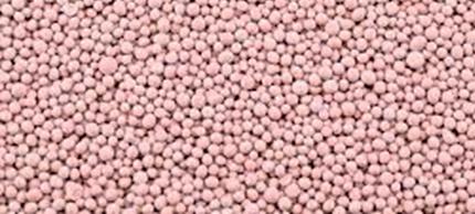


www.luengocolor.com info@luengocolor.com +34 93 736 14 76 AGROSEED ECO "THE MOST NATURAL FOR NATURAL ENVIRONMENT"
WORLD NEWS
POLAND Azoty Group S.A. signs contract with thyssenkrupp Uhde for preparation and supply of ammonium nitrate plant
Azoty Group S.A. has signed a contract with thyssenkrupp Uhde for the preparation of licensing documentation and the supply of all process equipment for a concentrated ammonium nitrate solution plant to be built in Tarnów. The project’s implementation will mark another step towards fulfilling the objectives of the green deal. It will enhance production efficiency by substantially decreasing the energy intensity of the fertilizer manufacturing process, and will help to reduce energy consumption in the production process by over 250 000 GJ per year.
The plant will be built in Tarnów, on the premises of the Fertilizer Business Unit of Grupa Azoty S.A. It will replace the existing more energy-intensive plant and secure raw material for further production of nitrate fertilizers in Tarnów, including Saletrosan and Saletrzak. Its production capacity will be 1500 tpd of concentrated ammonium nitrate solution (100% equivalent) with a concentration of 94% or 86%.
The new plant will contribute towards reducing the consumption rates of basic raw materials, which will lower the plant’s operating costs. It will also mitigate the environmental impact of the fertilizer production process and lower the amount of wastewater generated in the process.
Incorporation of modern solutions in the design of process equipment and instrumentation and control automation will significantly enhance the overall technical safety of the plant.
Tomasz Hinc, President of the Grupa Azoty S.A. Management Board, said: “The construction of a modern, safe and less energy-intensive ammonium nitrate plant in Tarnów also creates opportunities for further development of the company’s product offering. Fertilizer production is one of the key areas of Grupa Azoty’s operations, and Grupa Azoty’s strategic development directions include further strengthening of the group’s position among the leaders in agricultural solutions in Europe.”
Dr. Cord Landsman, CEO thyssenkrupp Uhde, said: “This project for Grupa Azoty marks another milestone for us and will further strengthen our position as a technology provider in the fertilizer industry. We at thyssenkrupp Uhde are proud to be selected as the partner to provide a most efficient ammonium nitrate neutralisation plant. It’s a big step towards a more sustainable chemical industry. We are proud to say that we were the only licensor who could offer a referenced technology which is able to use low-pressure gaseous ammonia as feedstock without requiring an ammonia compressor. This project proves that we can offer advanced ammonium nitrate technologies to the market and deliver the best solutions for our customers.”
The next stage of work is to design the ammonium nitrate production facility and associated facilities, followed by execution of contracts with contractors and the start of construction, which is scheduled for late 1Q24/early 2Q24, with completion due in 4Q25.
BRAZIL Petrobras to resume operations at fertilizer plant in Paraná
Jean Paul Prates, Petrobras CEO, has announced that plans to resume fertilizer production at Araucária Nitrogenados (ANSA), a subsidiary of Petrobras, are in their final stages.
After the completion of technical and financial feasibility studies, the matter must also be reviewed by the Executive Board and the Board of Directors of the company. The plant has been deactivated since 2020 and, after receiving investments and adaptations to meet the regulatory standards, it could begin operating again in the first half of 2024.
According to Jean Paul Prates, the fertilizer industry has strategic importance for Petrobras and the country: “Brazil is a major producer of agricultural commodities, but it depends on foreign fertilizers. This market has been facing many challenges around the world. Petrobras is interested in investing in the reactivation of ANSA due to the unit’s synergy with Repar. In addition to reducing the country’s dependence on foreign imports, with this operation we will generate jobs and income.”
ANSA has the capacity to process around 1900 tpd of urea and 1300 tpd of ammonia, used in the production of agricultural fertilizers, in addition to other industries. The raw material used in this unit is asphalt residue, which can be obtained from the Presidente Getúlio Vargas Refinery (Repar), also located in the city of Araucária.
SEPTEMBER 2023 | WORLD FERTILIZER | 5
SAUDI ARABIA FLSmidth to deliver beneficiation equipment to phosphate mine
FLSmidth has been chosen to supply the key technologies and services for Ma’aden’s Phosphate 3 Phase 1 mine site in the Northern province of Saudi Arabia.
The order is valued at approximately DKK 530 million and was booked in 3Q23. The equipment is expected to be fully integrated during 2025.

FLSmidth has partnered with Ma’aden from the onset of the new phosphate mine operations starting with initial laboratory testing of samples retrieved from the ore body in 2019 through to the development of the flowsheet and pilot scale testing. The focus of the collaboration is to ensure that the integrity of the flowsheet is maintained, while ensuring that the technology is well integrated into the overall plant design to deliver best possible performance from the process plant operations.
With this new order, FLSmidth will supply all the key equipment associated with the phosphate beneficiation plant as well as technical support services through the design, construction, commissioning and ramp-up phases. The order includes both primary and secondary sizers, apron and HAB feeders, cone crushers, screens, cyclone clusters, ball mills, paste and high-rate thickeners, horizontal belt filter, slurry pumps, knife-gate valves and flotation columns.
Mikko Keto, CEO at FLSmidth, commented: “We are pleased to collaborate with Ma’aden on this expansion, as this order sets another strong standard for our MissionZero agenda. In particular the incorporation of our paste thickening and dewatering technology at this important mine site plays a key role in reducing emissions and water spend from the beneficiation process.”
GERMANY Bindewald & Gutting Milling Group partner with Yara Germany to decarbonise cereal cultivation using green fertilizer
Yara Germany, Bindewald & Gutting Milling Group, and Harry-Brot have signed a cooperation agreement aimed at decarbonising cereal cultivation in Germany through the use of green fertilizers. For this purpose, Norwegian ammonia produced with hydropower will be processed in Rostock.
As early as the 2023/24 growing season, contract farmers of the Bindewald & Gutting Milling Group will use Yara’s green fertilizer on an area of around 1600 ha. The fertilizer will be produced from green ammonia at a plant in Rostock, Germany.
Unlike traditional methods that use fossil fuels like natural gas for ammonia extraction, green ammonia is produced using renewable energy sources such as wind, hydropower, or solar energy. This process involves obtaining the necessary hydrogen for ammonia synthesis through electrolysis. The outcome is a fertilizer with up to 90% reduced CO 2 footprint, compared to conventional methods.
Yara Germany, all nine locations of the Bindewald & Gutting Milling Group, and Harry-Brot signed a cooperation agreement with the shared goal of reducing CO 2 emissions in cereal production. The partnership will help reduce the carbon footprint of the entire food value chain, starting from fertilizers, to sales, and ultimately reaching end consumers.
WORLD NEWS 6 | WORLD FERTILIZER | SEPTEMBER 2023 NEWS
Ministry of Mines pledges support for Kola potash project thyssenkrupp Uhde signs contract to develop Han-Ho H2 Hub project Minbos secures site for Capanda green ammonia project South Harz Potash Limited announces new Non-Executive Director Visit our website for more news: www.worldfertilizer.com
HIGHLIGHTS

WORLD NEWS
DIARY DATES
AUSTRALIA thyssenkrupp Uhde and Orica partner to reduce nitric acid plant emissions
Orica and thyssenkrupp Uhde have completed the Kooragang Island Decarbonisation Project in Newcastle, Australia, with the commissioning of thyssenkrupp Uhde’s EnviNOx® technology to reduce greenhouse gas emissions at Orica’s three on-site nitric acid plants. For this project, thyssenkrupp Uhde provided the proprietary equipment, including the reactor vessels and the catalysts. Orica is a leading mining and infrastructure solution provider with a global manufacturing capability.
ANNA 2023
10 – 15 September 2023
Varna, Bulgaria anna-eu.com
Turbomachinery & Pump Symposium
26 – 28 September 2023
Houston, Texas tps.tamu.edu
Sulphur + Sulphuric Acid 2023 Conference & Exhibition
06 – 08 November 2023
New Orleans, USA events.crugroup.com/sulphur/home
Fertilizer Latino Americano 2024
05 – 07 February 2024
Florida, USA events.crugroup.com/ fertilizerlatinoamericano/home
With the EnviNOx technology, it is anticipated that this project will eliminate approximately 567 000 tpy of carbon dioxide equivalents from the site, which equals the annual emissions from 50 000 Australian homes. This reduction in greenhouse gas emissions corresponds to 48% of the site’s total greenhouse gas emissions and 11% of all chemical industry emissions in Australia.
Dr. Cord Landsmann, CEO at thyssenkrupp Uhde, said: “With our proven EnviNOx technology, we at thyssenkrupp Uhde are making a significant contribution to the elimination of greenhouse gas emissions, thus improving the sustainability of manufacturing and reducing the carbon footprint of industries. We are committed to a more sustainable future and therefore support our customers in achieving their sustainability goals using our proven technologies across the value chain.”
In acknowledging a significant decarbonisation milestone, Orica Managing Director and Chief Executive Officer Sanjeev Gandhi said: “This project clearly demonstrates that with the right policy settings and corporate commitments, emissions reduction is possible in hard-to-abate industries of our economy. We will continue to invest across our operations, to ensure Australian manufactured products remain competitive as the world transitions to a lower carbon economy.”
USA Phospholutions raises funds to accelerate commercialisation of higher efficiency fertilizers
Phospholutions Inc. has announced an additional US$10.15 million investment from leading global fertilizer companies and investors to accelerate the commercialisation of RhizoSorb® in the US row crop market. RhizoSorb is a patented technology incorporated upstream into the production process for conventional phosphates that reliably reduces phosphorus applications by up to 50%.
The financing was led by Advantage Capital and includes continued investment from Conti Ventures (a division of Continental Grain Company), Tekfen Ventures, Maumee Ventures, and Ben Franklin Technology Partners. Keytrade, a global fertilizer trader, also joins as a new investor.
“We are pleased to welcome new investors like Advantage and Keytrade supporting our efforts to accelerate commercialisation of our phosphate efficiency technology. Additionally, the continued support from our existing investors really fortifies what we are doing to bring new sustainable fertilizers to the US farmer,” says Jason Burke, Vice President of Finance at Phospholutions.
8 | WORLD FERTILIZER | SEPTEMBER 2023
Protect Assets with Superior Service and Specialty Chemical Expertise
SOLUTIONS TO MAXIMIZE ASSET VALUE
Halliburton Multi-Chem provides specialty water and process treatment chemicals, customized engineering solutions, and services to the industrial sector, including the ammonia/ fertilizer, refining, petrochemical, chemical and power industries.
We successfully serve America’s largest refineries and ammonia plants. As your partner in asset integrity, we are committed to helping you achieve production reliability and preserve capital equipment.
Ensure ammonia/fertilizer production reliability and preserve capital equipment. Effective water and process treating is imperative to successful ammonia and fertilizer plant operations.
Large amounts of high pressure steam and high purity water are required in the production process. Halliburton Multi-Chem has a long and successful track record in the following areas:
» Raw water pretreatment
» Cooling water
» Boiling feedwater
» Steam
» Processor condensate
» CO2 removal
» UAN corrosion inhibition
» Value-add projects

halliburton.com
© 2023 Halliburton. All Rights Reserved.
Multi-Chem
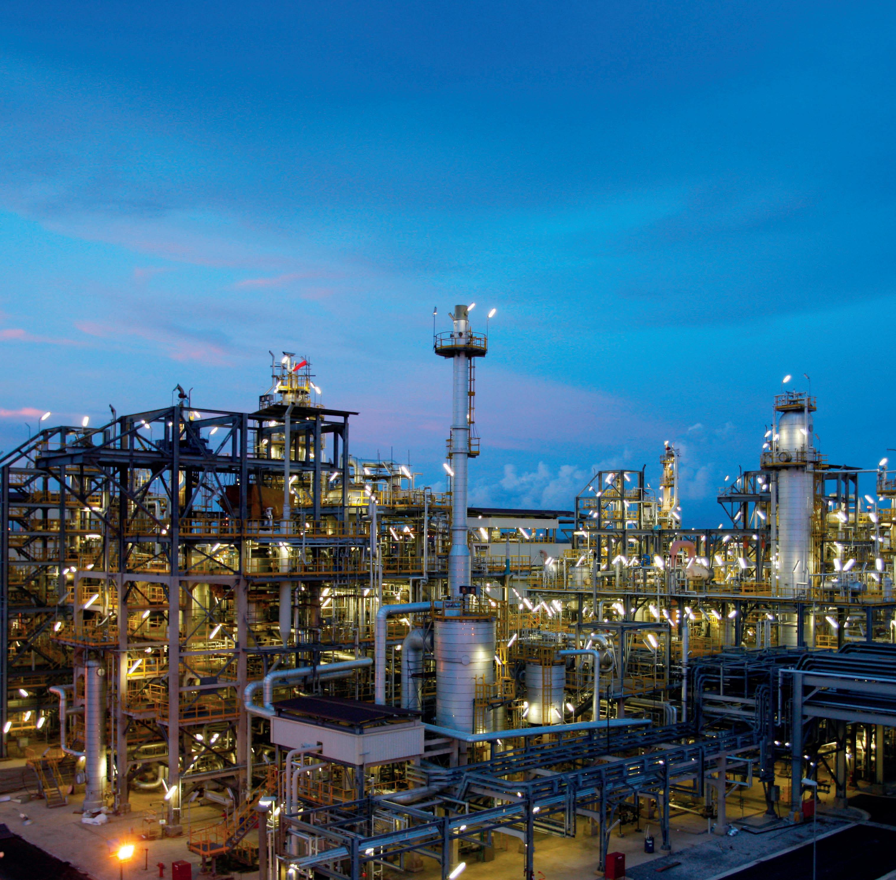
While the major upheaval in global fertilizer, energy and commodity markets triggered by the conflict in Ukraine dissipated to an extent as 2023 progressed, the disruption to natural gas flows and prices continues to reverberate throughout the ammonia industry in particular.
At the height of the turmoil last year, around two thirds of European ammonia production capacity was curtailed as natural gas prices spiked to eye-watering levels and manufacturers idled plants and scrambled to secure import cargos – albeit at hugely elevated prices.
The loss of around 3 million tpy of Russian ammonia due to the closure of the pipeline to the Black Sea port of Yuzhnyy had already prompted a significant period of uncertainty and volatility, while a regular flow of Russian cargoes from Baltic ports also dried up quickly – although limited exports did return to the market in mid-2023 via the port of Ust-Luga.
Those high prices created plenty of lucrative sales opportunities for suppliers with the ability and/or agility to satisfy Europe’s appetite for foreign material, with cargoes moving to the continent from as far afield as Indonesia, Brazil and the Middle East.
The supply squeeze started to ease in the first few months of 2023 as feedstock costs finally fell and many of the European plants that had been idled came back onstream, albeit not at high operating rates, as companies juggled their budgets between domestic production and imported material.

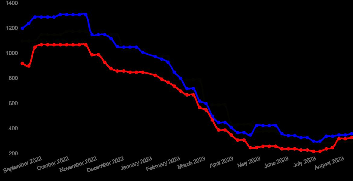
This improved supply/demand balance and a return to market normality was clearly reflected in the downward price trend, which saw leading indices drop back to levels last witnessed in early 2021. As an illustration, the US benchmark – the Tampa cost and freight index – plummeted from over US$1 000/t in January 2023 to below US$300/t just six months later.
With that monthly settlement contract price impacting several other leading indices, falls were also registered in the Trinidad spot FOB (free on board) index, which plummeted by around 75% over the same six-month period.
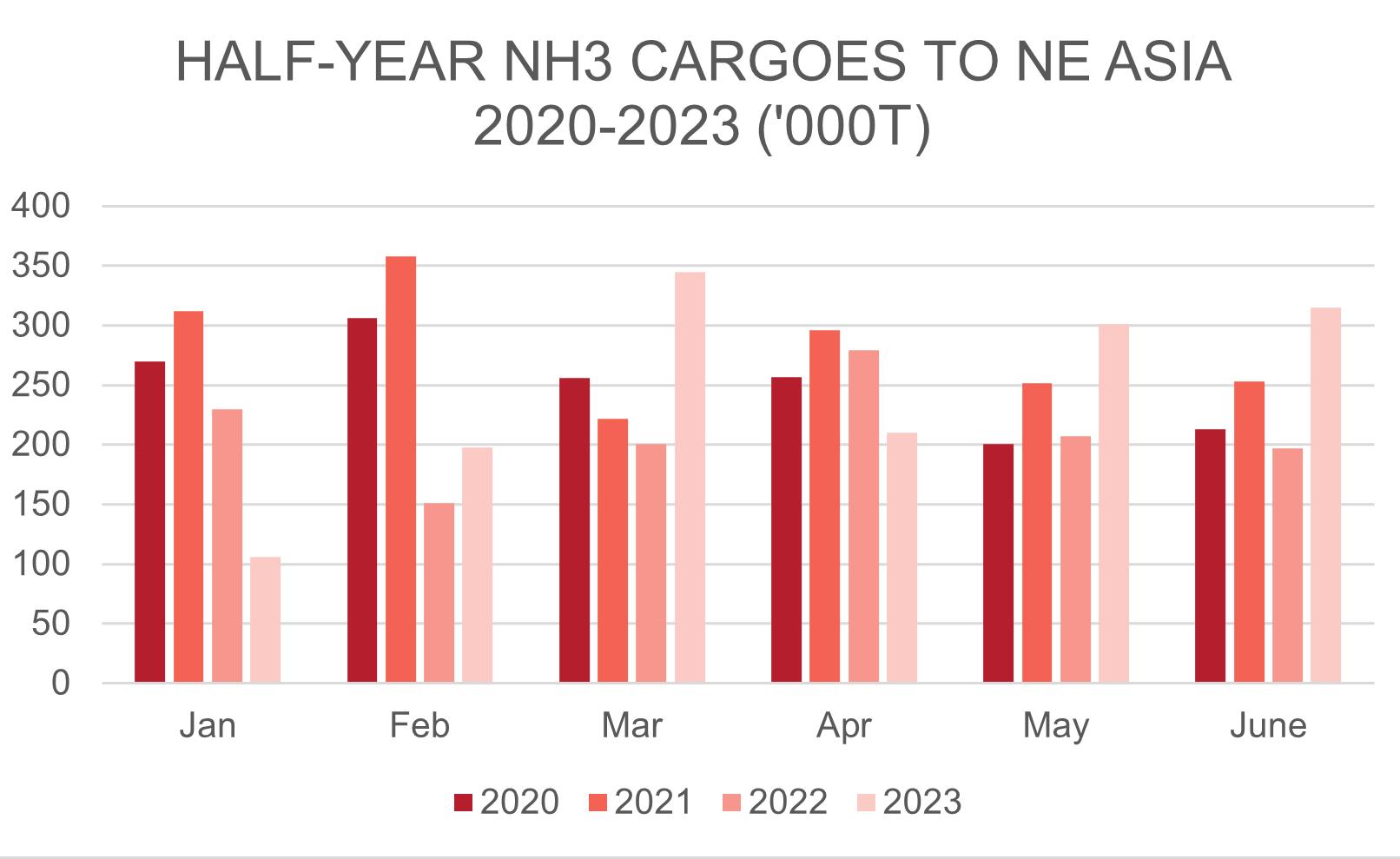
A similar picture emerged east of Suez, with key FOB and CFR indices dropping sharply, particularly those in the Middle East and Asia Pacific. This encouraged buyers back into the market (Figure 1), underlining the relative
10
THE GREEN LIGHT FOR BLUE AMMONIA
Richard Ewing, Profercy Nitrogen, United Kingdom, explains how the low-carbon ammonia revolution is gathering pace as established players and new names look to take advantage of the development of cutting-edge technologies.

11
strength of import demand in China, Taiwan, South Korea and Japan in January – June 2023 compared to recent years.
Total shipments to the quartet in 1H23 were similar to 2020 levels and came in the wake of years of COVID-19 disruption.
While the price falls were welcomed by buyers, it was tempered for those in Europe – who had benefitted from the European Commission’s suspension of import duties (5.5% for product from most origins) for six months – as regulators reimposed the trade levy during the second quarter.
One aspect of the major disruption to traditional trade flows and supply routes that should not be overlooked is the speed at which the market adjusted and how participants overcame the supply shock with an impressive agility and pace.
These successful trading patterns bode well for current players, new investors and future market entrants planning low-carbon (blue) and zero-carbon (green) ammonia production facilities as the nitrogen fertilizer industry seeks to decarbonise its own environmental footprint, as well as those in the crop nutrient, energy and transport sectors.
It is fair to say that the recent market turmoil in the European ammonia market has likely accelerated its long-term demise, with producers that run plants both sides of the Atlantic able to move competitively priced material from the
Americas to their own systems in Europe or those of customers.
Major names like Yara, OCI Global (Fertiglobe) and CF Industries regularly loaded substitute cargoes at ports in Texas and Louisiana for ports ‘across the pond’ and that trend is likely to grow and grow over the coming decade, as world-scale and efficient plants running on low-priced natural gas and benefitting from attractive financial incentives spring up along the US Gulf coastline.

At the same time, as European ammonia capacity is curtailed permanently – BASF and CF Fertilisers UK have both recently announced shutdowns of well-established plants in Germany and the UK, respectively – the pace of new US to Europe trade flows is about to notch up a gear.
In addition, with the ammonia industry responsible for around 2% of global emissions per year and the shipping sector responsible for a further 3% of greenhouse gas emissions, the switch to blue and green ammonia by the maritime industry could effectively kill two birds with one stone.
Many leading players in the shipping sector are investing in dual fuel-powered tankers as they prepare for this new energy chapter, with ammonia considered the frontrunner by many ahead of rival fuels like methanol and LPG.
The green light for blue ammonia projects
Over the past couple of years, tens of billions of dollars of investment in ‘clean’ (green/blue) ammonia plants has been pledged by industry names such as Yara, Nutrien, CF Industries and Copenhagen Infrastructure Partners (CIP) for projects in the US Gulf.
Encouraged by generous financial support from federal and state governments – including lucrative subsidies under the Inflation Reduction Act (IRA) – the companies are set to transform the region into a clean ammonia export hub, serving agricultural and industrial markets across the world. Yara believes IRA tax credits, including US$85/t of CO2 stored, will create an attractive tax credit of close to US$150 of blue ammonia.
Several of the potential projects – which all boast at least 1.1 million tpy of capacity and include facilities in Canada and West Virginia – involve Japanese traders eager to supply clean product to the large industrial markets of Japan and South Korean.
Planned offtakes by Mitsui and Mitsubishi are among the supply chains that will satisfy the appetite for ammonia from energy and chemical makers in Northeast Asia. Japan alone intends to import at least 250 000 tpm of clean ammonia from 2030 as part of its ambitious decarbonisation drive.
Of course, North America is not alone in targeting this exciting new market, with dozens of projects also announced for countries throughout the Middle East, Southeast Asia, Latin America and Africa. While some of those will focus on hydrogen production, the material will be moved as ammonia, given the relative ease of moving it in liquid form.
According to Hassan Badrawi, Chief Financial Officer of Dutch fertilizer company, OCI Global, one of the biggest drivers towards an accelerated move to carbon neutrality remains regulation and financial support from governments.
12 | WORLD FERTILIZER | SEPTEMBER 2023
Figure 1. Imports are flowing freely into NE Asia after several lean years.
Data from Profercy Hub https://profercyhub.com
Ammonia: Arab Gulf $pt fob Spot
Ammonia: NW Europe $pt cfr duty paid
All data is copyright Profercy Ltd. All rights reserved.
Ammonia: Tampa $pt cfr
3
Figure 2. Ammonia price graph.
Invisible. Invaluable.
Black & Veatch has over 80 years of experience executing projects that maximize throughput and uptime on facilities’ operating assets. With minimal disruptions to operations, we work behind-the-scenes to complete projects safely, on time, and to the highest quality standards.
• From front-end project phases to full EPC, Brownfield to Greenfield.
• Plants completed in sizes ranging from 50 to 2,500 metric tons per day.

• Projects include studies, revamps, ammonia storage, and terminal facilities.

Let’s find ways to help you.
While high natural gas prices might encourage people to think more about alternatives, he notes, the reality is that it takes long-term planning and investment to bring these projects online and businesses that want to make the move are doing it anyway.
“Today, making a lower carbon version of methanol or ammonia is more costly, whether this is the cost to capture carbon dioxide (CO2) or to utilise renewable feedstocks that cost much more than fossil fuels,” he says.
“However, with economies of scale and time, the costs will come down as we have seen with so many other new technologies in the past like solar and wind.”
“In the short-medium term, the higher cost would need a green premium to justify it economically, and that is where regulatory support must come in to establish that premium. The IRA in the US, for example, has allowed global distributors and producers of low-carbon fuel alternatives to accelerate decarbonisation projects thanks to the tax credits system supporting carbon sequestration."
“On that basis, organisations like OCI Global [which has already begun construction of a 1.1 million tpy blue ammonia plant in Texas due to launch in 2025] can take the low-hanging fruit and move forward more quickly with less risk.”
This upbeat view was echoed by
Magnus Krogh Ankarstrand, President of
Yara
Clean Ammonia
(YCA), during the Norwegian giant’s late June unveiling of a potential world-scale low-carbon blue ammonia production facility on the US Gulf Coast featuring state-of-the-art carbon capture technology.
Together with German chemicals major BASF, YCA is looking into the feasibility of a huge plant with a total capacity of 1.2 – 1.4 million tpy to serve the growing global demand for low-carbon ammonia.
“We are working systematically to develop asset-backed supply to decarbonise agriculture as well as serving new clean ammonia segments such as shipping fuel, power production and ammonia as a hydrogen carrier,” he said.
So far this year, regular-sized cargoes of verified blue ammonia from the Middle East have been delivered to recipients in nations including Bulgaria, India, South Korea, Taiwan and Thailand, albeit at a price in line with traditional ‘grey’ ammonia. For many of those buyers, the procurement of low-carbon feedstock has allowed them to brand agricultural and industrial derivatives as blue.
With such massive worldwide momentum, the clean ammonia industry presents plenty of openings and opportunities in the upstream and downstream sectors, including in the transportation and storage of the liquid volume.
What is less clear is how buyers can be encouraged to swap grey ammonia for the more environmentally friendly grades given that the latter attracts extra costs, with governments expected to introduce a raft of taxes and duties to speed up the switch to such alternatives.
At present, all eyes are on officials in countries across Europe and Northeast Asia as they seek to maintain the push towards clean ammonia. At the same time, these officials are not being seen to deliver financial punches to buyers who recognise the need to decarbonise.
In Europe, the EU’s Carbon Border Adjustment Mechanism (CBAM) is described as a “landmark tool to put a fair price on the carbon emitted during the production of carbon intensive goods that are entering the EU, and to encourage cleaner industrial production in non-EU countries.”
Due to commence a transitional phase this October before it comes into permanent force from 2026, “importers will need to declare each year the quantity of goods imported into the EU in the preceding year and their embedded greenhouse gas emissions (GHG).”
“They will then surrender the corresponding number of CBAM certificates.” State regulators add that “the price of the certificates will be calculated depending on the weekly average auction price of EU Emissions Trading System (ETS) allowances expressed in €/t of CO2 emitted."
Other national and regional approaches to the shift to clean ammonia have yet to fully emerge, but with global fertilizer, chemical, energy and shipping industries all singing from the same song sheet, the market is set to undergo a lengthy period of fundamental change in which there will be more winners than losers, including future generations.
14 | WORLD FERTILIZER | SEPTEMBER 2023
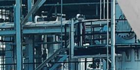
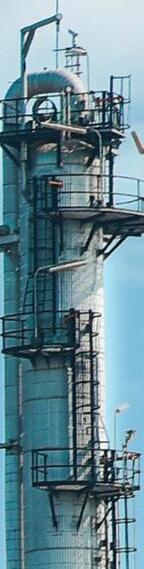
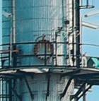
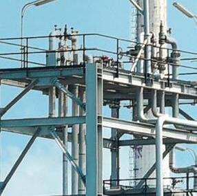
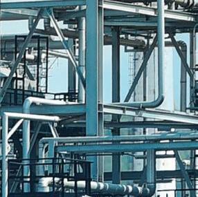
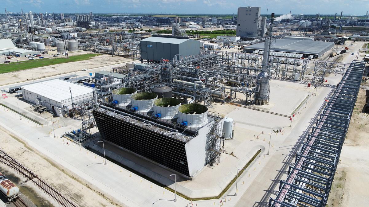
Figure 3. Yara and BASF already operate an ammonia plant JV in Texas. (Image courtesy of BASF SE).
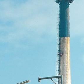
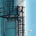
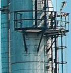
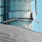
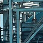
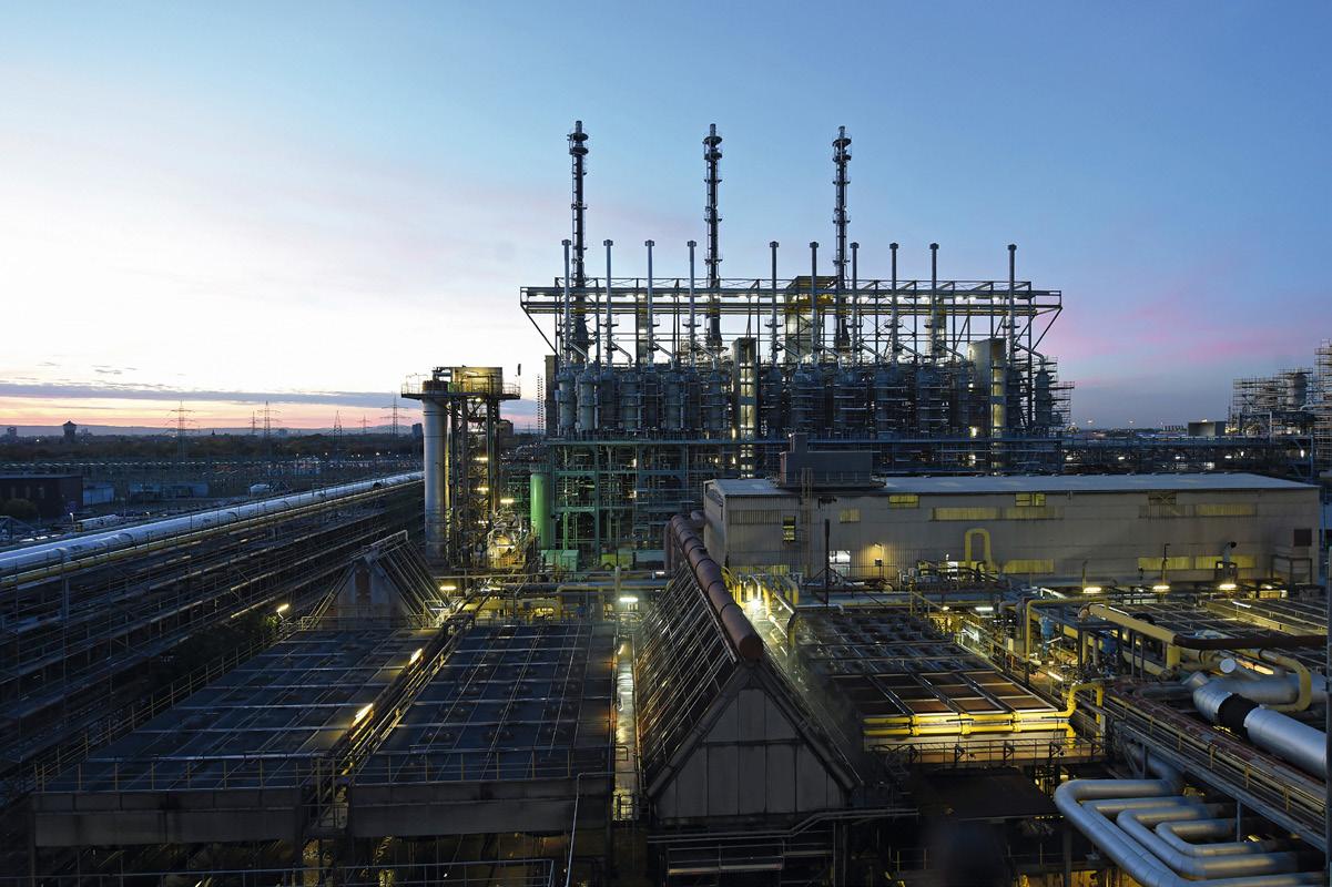
Figure 4. BASF has closed one of its two ammonia plants at Ludwigshafen, Germany. (Image courtesy of BASF SE).


16
Kevin Rouwenhorst, Proton Ventures, the Netherlands, discusses the many applications for green ammonia, from the fertilizer sector to use as a hydrogen carrier.
Ammonia is becoming more commonly used as a zero-carbon fuel and hydrogen carrier, and announcements of new green ammonia production plants are commonplace.
Proton Ventures has been involved in this emerging landscape, through projects such as scoping studies, feasibility studies, FEEDs (front end engineering designs), and EPC (engineering, procurement and construction) projects. The company takes a 'technology agnostic' approach as a

17
system integrator, allowing the most suitable licensors and original equipment suppliers (OEMs) to be selected for the specific project.
Green ammonia production for fertilizer applications
Green ammonia production has been a key focus throughout the last two decades. Instead of focusing on world-scale ammonia plants producing up to 1 million tpy, Proton Ventures has focused on modular ammonia plants with a production capacity in the range of 3 – 60 tpd of ammonia. This allows ammonia plants to be located next to modular electrolysers combined with solar PV and wind capacity. The modular approach also helps improve the flexibility of the plant overall.
The company is currently executing an EPC project for a 4 tpd green ammonia pilot plant (GAPP), to be built
at the OCP Group chemical complex in Jorf Lasfar, Morocco. This pilot facility will consist of both a 2 MW alkaline electrolyser and a 2 MW PEM electrolyser for hydrogen production, compressed hydrogen storage, nitrogen purification, and a Haber-Bosch ammonia synthesis loop. Another key aspect of the project is the emulator that can simulate electricity profiles from anywhere around the world. Thus, this facility will help enable the derisking of large-scale green ammonia facilities. Proton Ventures will initially operate the facility for about a year, after which the facility will be operated by the Mohammed VI Polytechnic University. In this period, future engineers in the green ammonia industry will be trained.
Morocco is currently the third largest ammonia importer after the United States and India, with about 1.8 million t of ammonia imported to the country in 2020. Morocco does not have its own natural gas resources, but it boasts about three quarters of the global phosphate rock reserves. Ammonium phosphate fertilizers such as monoammonium phosphate (MAP) and diammonium phosphate (DAP) are currently produced in Morocco from phosphate and imported ammonia. Local green ammonia production may eliminate imports, while also decarbonising the carbon footprint of Moroccan ammonium phosphate fertilizer production. The GAPP project acts as a first step toward large-scale green ammonia production in Morocco.
Green ammonia for intercontinental trade
Proton Ventures is also active within the TransHydrogen Alliance, which aims to produce ammonia in areas with abundant solar and wind resources, such as Brazil and Morocco, with subsequent transport and cracking of ammonia to hydrogen in Rotterdam, the Netherlands. The aim is to produce ammonia at a larger scale, e.g. up to 1 million tpy. The benefit of the TransHydrogen Alliance is that production and utilisation are coupled, ensuring supply, while keeping the overall system cost low.
18 | WORLD FERTILIZER | SEPTEMBER 2023
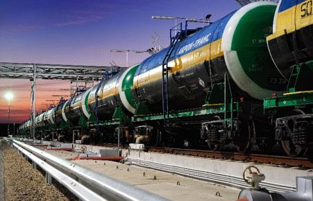
Figure 1. Railcar loading and unloading facility in Sillamäe, Estonia. Copyright: Proton Ventures B.V.
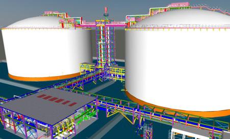
Figure 2. 3D image of an ammonia storage facility (FEED+ engineering package) in the United Arab Emirates. Copyright: Proton Ventures B.V.


A World Leader in Catalyst Support Media KEY PROCESS COMPONENTS FOR NITROGEN AND PHOSPHATE FERTILIZER PRODUCTION FACILITIES Christy Catalytics, LLC Certified ISO 9001:2015 Tel.: +1-314-773-7500 CATCO@christyco.com www.christycatalytics.com
These projects are mainly based on currently available technology, however, Proton Ventures is also working on solutions for ammonia synthesis, such as novel electrolyser technologies, and improving ammonia synthesis technologies.
Improving hydrogen production via electrolysis is key, as the production process typically accounts for at least 90% of the energy input for ammonia production.
Proton Ventures has aided the development of the Battolyser, which is a combination of an iron-nickel battery and an alkaline type electrolyser. Within the EU project ARENHA, the company has also patented a low pressure ammonia synthesis technology that can significantly improve the single pass conversion via a sorbent-enhanced separation step. The demonstration plant is currently under construction.
Ammonia storage and handling
Some of the largest projects executed by the country are its refrigerated storage tanks in Estonia (BCT) and Bulgaria (Agropolychim), which are among the largest operating ammonia storage tanks in Europe. The two tanks in Estonia each have a capacity for 30 000 t of refrigerated ammonia at -33°C. The tanks are double containment storage tanks complying with modern safety standards. The facilities in Estonia also consist of railcar loading and unloading systems, a marine loading arm facility, and four UAN tanks of 20 000 t each.
The global trade of ammonia is set to expand over the coming decade, as the use of ammonia as shipping fuel, as stationary fuel, and as a hydrogen carrier, is taking off. In light of these developments, Proton Ventures and consortium partners have been awarded a turnkey contract by OCP Group for two refrigerated ammonia storage tanks in Jorf Lasfar, Morocco. The company is also currently investigating the revamping of two storage tanks operated by Vesta Terminals in Vlissingen, the Netherlands.
Requirements for new ammonia storage tanks must be complied with, even when located in desert areas with temperatures sometimes measuring in excess of 50°C. Recently, a FEED+ engineering package was completed for a new ammonia export terminal in the United Arab Emirates, and a special main discharge bottom valve was required for inherent safety. Intermittent flaring and an interconnecting bridge between the two storage tanks with a combined staircase optimised the capital investment, spatial utilisation, and simplicity. Furthermore, the refrigeration system design is optimised for hot climate operations and low operational costs.
Nitrogen oxide emissions
When ammonia is utilised as a fuel or for nitric acid production, nitrogen oxide emissions must be mitigated. NO X emissions are mainly a local issue, causing eutrophication. On the other hand, nitrous oxide (N 2 O) has a global warming potential (GWP) equivalent to 298 times that of CO 2 .
Nitrogen oxide emissions can be mitigated by reacting nitrogen oxides with ammonia in a selective
catalytic reduction (SCR) system, resulting in the production of unharmful atmospheric dinitrogen and water. Within the EU, most nitric acid plants are equipped with such SCR systems, nearly eliminating N 2 O emissions from these plants. Around the rest of the world, this is not yet standard practice, and therefore nitrogen oxide is low hanging fruit in the global effort to decarbonise.
Proton Ventures was contracted as EPC contractor by Kavala Fertilizers in Greece for DeNO x and N 2 O reduction with an SCR system at a nitric acid plant. This DeNO X system saves about 20 000 t of CO 2 e emissions annually, while meeting the most stringent nitrogen oxide emission standards. The SCR system has also eliminated the yellow plume from the nitric acid plant.
Such SCR systems can also be used for ammonia conversion for energy applications, such as gas turbines and maritime engines. In fact, various gas turbines – currently fed with hydrocarbons such as natural gas – have already installed an SCR system, thus already handling ammonia onsite.
Hydrogen production
As ammonia becomes more abundant as an energy vector, its use as a hydrogen carrier is set to increase. Ammonia cracker facilities for hydrogen production are currently considered in various northern European ports, such as Rotterdam and Wilhelmshaven. Proton Ventures has performed various studies on ammonia cracking for clients, and remains active within various research consortia. Such centralised ammonia cracker solutions for pure hydrogen production are functionally very similar to natural gas processing plants for hydrogen production. Alternatively, decentralised ammonia cracker solutions are currently being developed, which do not always require full conversion and purification of the hydrogen, thereby improving the energy efficiency of the system and the cost.
To consolidate the solutions for ammonia cracking, Proton Ventures is currently operating a high pressure ammonia cracking testing facility at the high pressure laboratory at the University of Twente, the Netherlands. This is critical to validate the operational performance under industrially relevant conditions, while also allowing novel cracker concepts to be tested.
The next aim is to build a commercial pilot for ammonia cracking, which is an essential intermediate step for the industry to move towards world-scale hydrogen production facilities. A pilot plant is necessary, as performance in terms of ammonia feedstock utilisation is key for the cost of produced hydrogen. The ammonia feedstock cost can account for over 90% of the total levelised cost of hydrogen from ammonia cracking. Thus, ensuring minimal ammonia feedstock utilisation is paramount.
Leading by example
The ammonia economy will likely become a reality soon. Various decarbonisation projects for existing ammonia plants have already been realised, with newly built green ammonia plants under construction.
20 | WORLD FERTILIZER | SEPTEMBER 2023


Lab Scale Test 100 g batch Pilot Scale Test 1000 kg batch Industrial Solution 1 to 100 ton/hr
1.
2.
3.
AWHOLE AWHOLE AWHOLE
Ezio
and Manuel Crotta, Maire Tecnimont, Italy, consider how the metaverse is being integrated into fertilizer plant operations.
The metaverse is an immersive ecosystem in which various virtual worlds, interconnected with each other, emulate and enhance live experiences that users might be able to access, only in part, in the real world.
In the metaverse, users interact with this ecosystem and collaborate with each other, building a new framework of assets made of direct experiments, knowledge sharing and heuristic
 Pasqualon
22
NEWWORLD NEWWORLD NEWWORLD
learning, unlocking unimaginable value acquisition that can then be applied in the real world, with benefits including: increased safety levels, improved performance, and the spread of awareness and familiarity.
Briefly, the metaverse, powered by virtual mirroring of reality, enhances the human mind's extraordinary ability to learn through experience and imagination.

23
This article examines an example of a training simulation environment, based on the metaverse, that was recently designed and tested by MAIRE for fertilizer plants.
The metaverse applied to industrial plants
The digitalisation of MAIRE has enabled the company to develop solutions impacting on the entire plant lifecycle, with a particular focus on plant safety, production efficiency and operators’ upskilling.
The metaverse concept in fertilizer plants has been developed simply by customising the software tools and digital technologies developed and applied in other fields such as aviation, medicine and gaming. This is in response to the increasing demand from plant owners for solutions that improve traditional ways of training board and field operators, in a more efficient, effective and safer way than the traditional operator training simulators (OTS) and on-the-job training approaches.
In addition to this, subsidiaries of MAIRE, Tecnimont and Stamicarbon have created immersive training simulators (ITS) as a solution for meeting plant owners'
expectations of jointly training board and field operators in a realistic scenario as close as possible to the real plant.
ITS, therefore, as a combination of conventional OTS with a 3D model of the plant suitable for immersive navigation through virtual reality (VR) techniques, can help meet the needs of plant owners and industrialise a new methodology to achieve operator upskilling and reskilling, while succeeding in attracting the younger generation who are natively digital.
Today, several development tools are commercially available to make the 3D model immersive, but no immersive training simulators exist that combine the digital twin of the process and the digital twin of the asset customised for specific licensed plants. A collaboration such as the one seen between Stamicarbon and Tecnimont is an example of a mix of factors needed to develop an ITS for a fertilizer plant. By improving on the conventional approach to industrial training with the simulation of real processes and guided operating situations on how best to handle them, ITS enhances safety by:
n Eliminating the hazards of field training and the consequent risks of fatal accidents to people.
n Eliminating damage to the environment or assets in the event of human error during field interventions or plant operation managed by the control room.
ITS is a sustainability tool, since it enables enhanced plant productivity (by effective training of its operators), inclusiveness (by promoting upskilling and reskilling of plant operators to cope with turnover from retirement and trained teams), and safety (by creating a lifelike setting where trainees can gain practical and risk-free experience without facing threats or costs associated with training sessions performed in the real plant).
The potential of the metaverse applied to industrial plants
The metaverse suite industrialised as ITS by MAIRE combines these functionalities in a collaborative user-friendly platform:
n Asset digital twin: Consisting of a realistically rendered 3D model which incorporates the data (like P&IDs, datasheets, vendor O&M handbooks, etc.) typically developed by the EPC contractor during project execution.
n Process digital twin: Consisting of an advanced OTS which incorporates the licensor process knowledge of the physics and chemistry behind an industrial plant, including but not limited to thermo-fluid dynamics and kinetic modelling.
24 | WORLD FERTILIZER | SEPTEMBER 2023
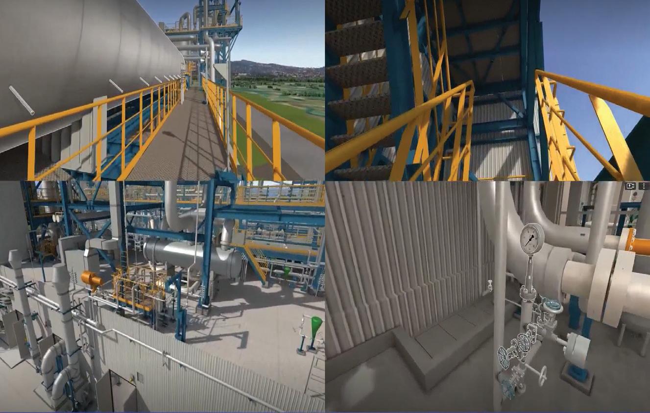
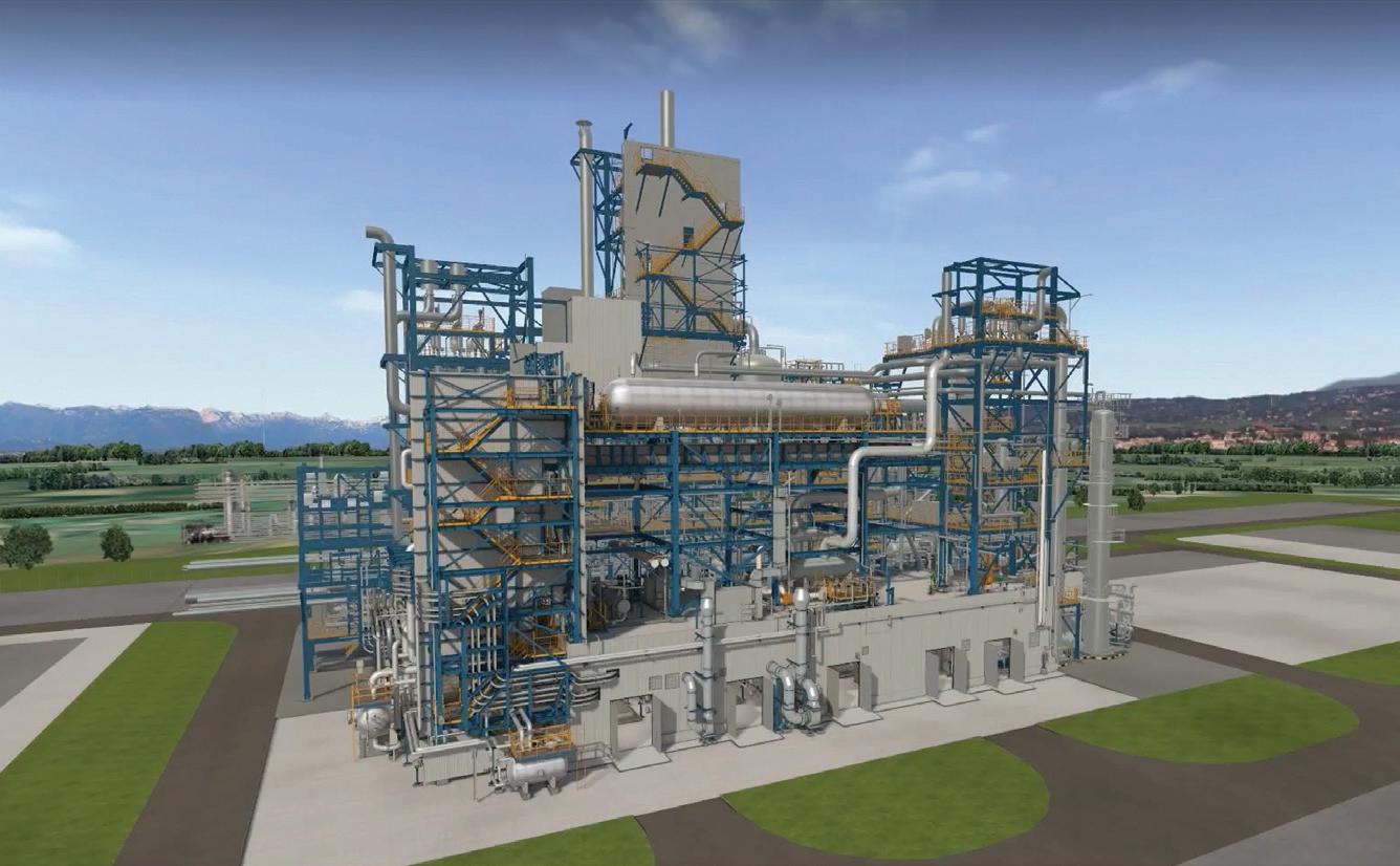
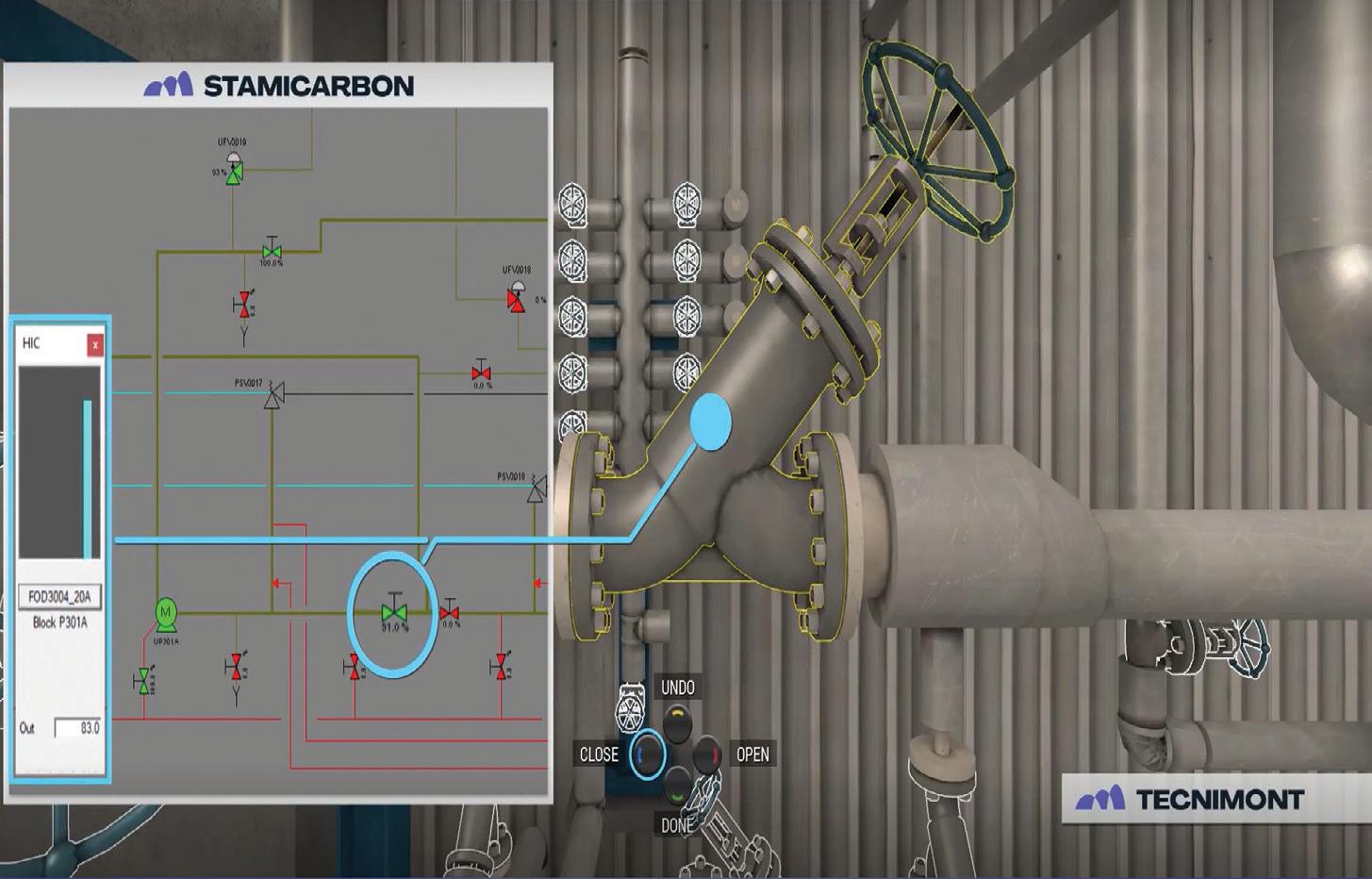
Figure 1. A urea plant licensed by Stamicarbon rendered in high quality.
Figure 2. Snapshots of a urea plant licensed by Stamicarbon suitable for 3D immersive navigation through VR.
SUPPORT SUSTAINABLE NATURAL GROWTH SEPARATION SOLUTIONS FOR AGROCHEMICALS AND FERTILIZERS
Let’s support agrochemical and fertilizer solutions that put nature first. We at ANDRITZ achieve this by providing you with the right separation technology, as well as extensive process experience!
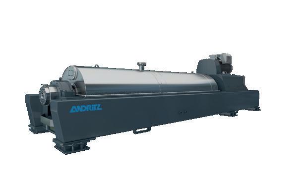
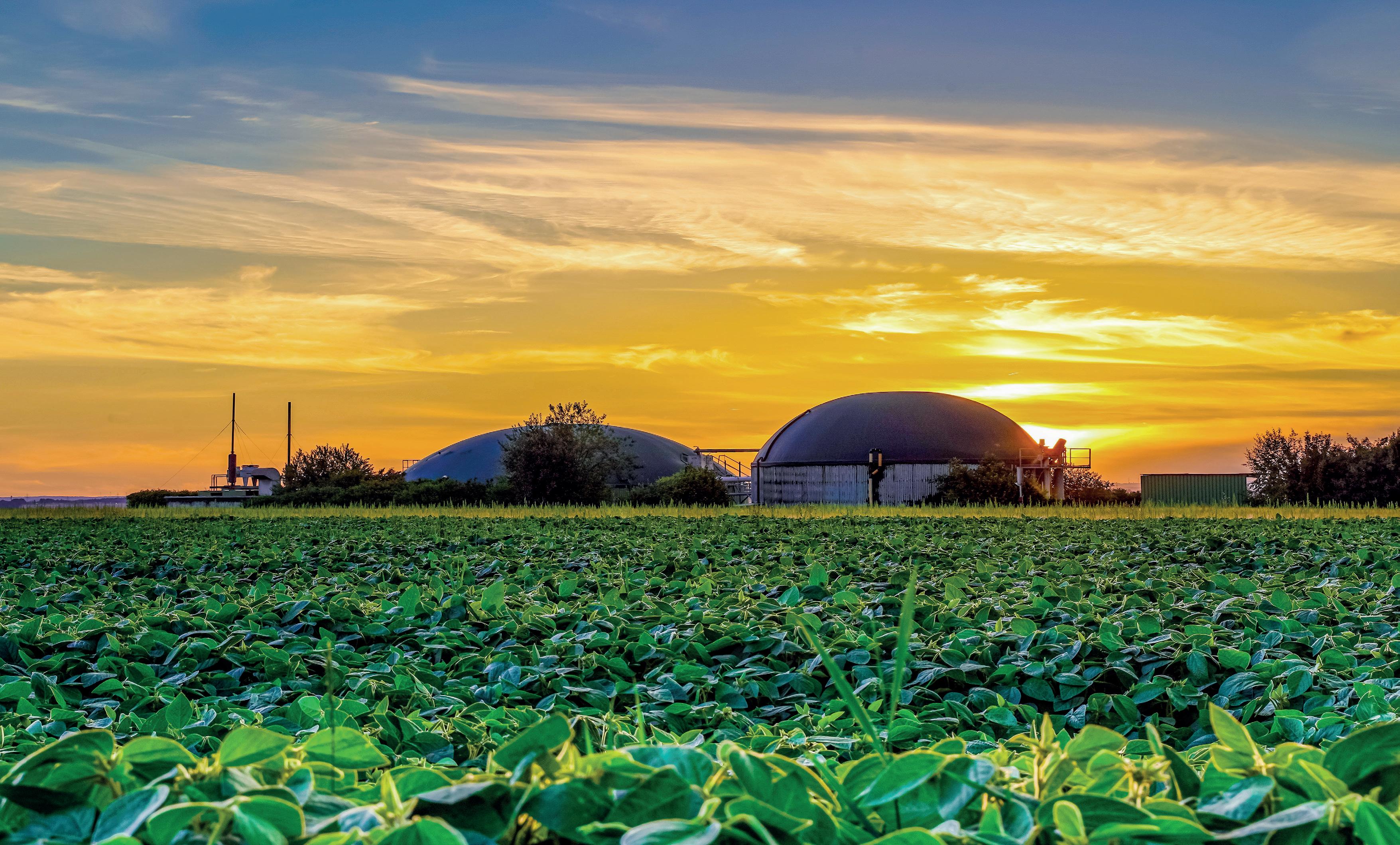
With our extensive portfolio of solid/liquid separation technologies and our team of separation specialists, we have both the capacity and the drive needed to create an environment where nature and humans can flourish and thrive together.
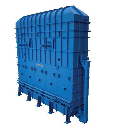
High-capacity drying lines for urea, potash, phosphoric acid, and ammonium sulfate as well as decanter and pusher centrifuges, filter presses, vacuum disc filters, and tilting pan filters – you name it. However your product is created, we most likely have everything you need for production: the technology, the process experts, the experience – all backed by proven service and innovative automation solutions.
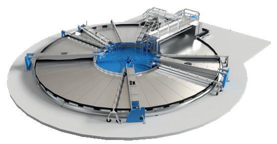
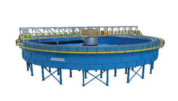
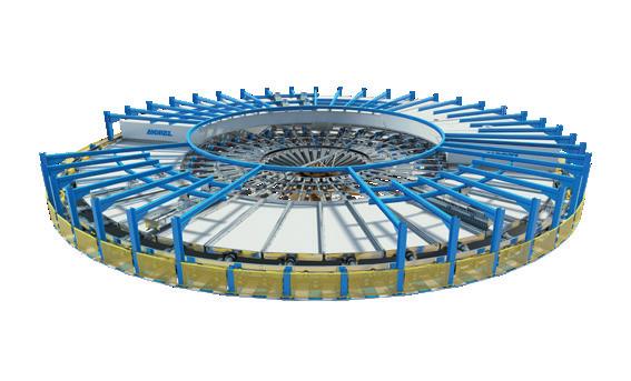
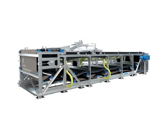
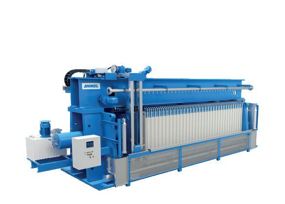
Whether you are a startup with an innovative idea for creating a new biofertilizer or reducing CO2, or a partner looking to improve efficiency in an existing process, our team is eager to support you in getting the most out of your process!
For more information, visit our website.
ANDRITZ AG / Stattegger Strasse 18 / 8045 Graz / Austria / separation@andritz.com / andritz.com/separation
The merging of these two domains assures that whatever action is performed in the virtual field, the same is detected and reflected in the OTS and vice versa, with a process response and reactiveness equivalent to the one experienceable in the real plant.
These two pillars of the ITS are further enhanced by add-ons which supplement its potentialities by connecting tools that are typically handed over to the plant owner as stand-alone solutions like a computerised maintenance management system (CMMS), predictive maintenance suite (PMS), remote assistance by excellence centres, etc.
In such a scenario, the physical model of the plant enriched by EPC-related data, the process model of the plant enriched by licensor know-how, and the live data related to plant maintenance are all merged into a metaverse ecosystem that can amplify the learning capabilities of the plant operator's staff.
This metaverse suite is accessible with a browser or a visor that allow engineers and operators to have
interactions and experiences in a virtual environment that recreates (in a multisensorial 3D space) the ‘real plant’ with a level of perceived accuracy comparable to high quality VR technology, gaming technique, and IoT (Internet of Things) features currently available on the market.
In addition to training applications, the ITS allows designers (from licensor to EPC engineering teams) to test themselves in the environment they are creating 'virtually on paper and on calculations', revealing valuable insights that can be used to improve their design towards greater safety and better performance, before handing it over to the plant owners where chance of return is minimal.
Conclusion
ITS creates an immersive and realistic experience for the users, where any action corresponds to reactions which virtually emulate dynamic behaviours of the real plant.
Whatever action is performed in the virtual field, the same is detected and reflected in the OTS and vice versa, with a process response and reactiveness equivalent to the thermo-fluid-kinetics dynamics of the real process and plant.
In this unique environment, board operators and field personnel are connected together in real time in a realistic, high-fidelity replica of the plant. Operators can safely test and experience operational scenarios, ordinary routine activities and extraordinary emergency situations, as well as learn by practicing how to operate the plant and handle events which they will or may face in the future.
Furthermore, when ITS is used for training purposes, the system automatically tracks errors allowing lesson learning and cold-eye review assessments.
The system allows data to be connected to tagged items displayed in the plant’s virtual replica by providing, at a glance, comprehensive information to trainees, facilitating the handover from the EPC to the O&M phase.
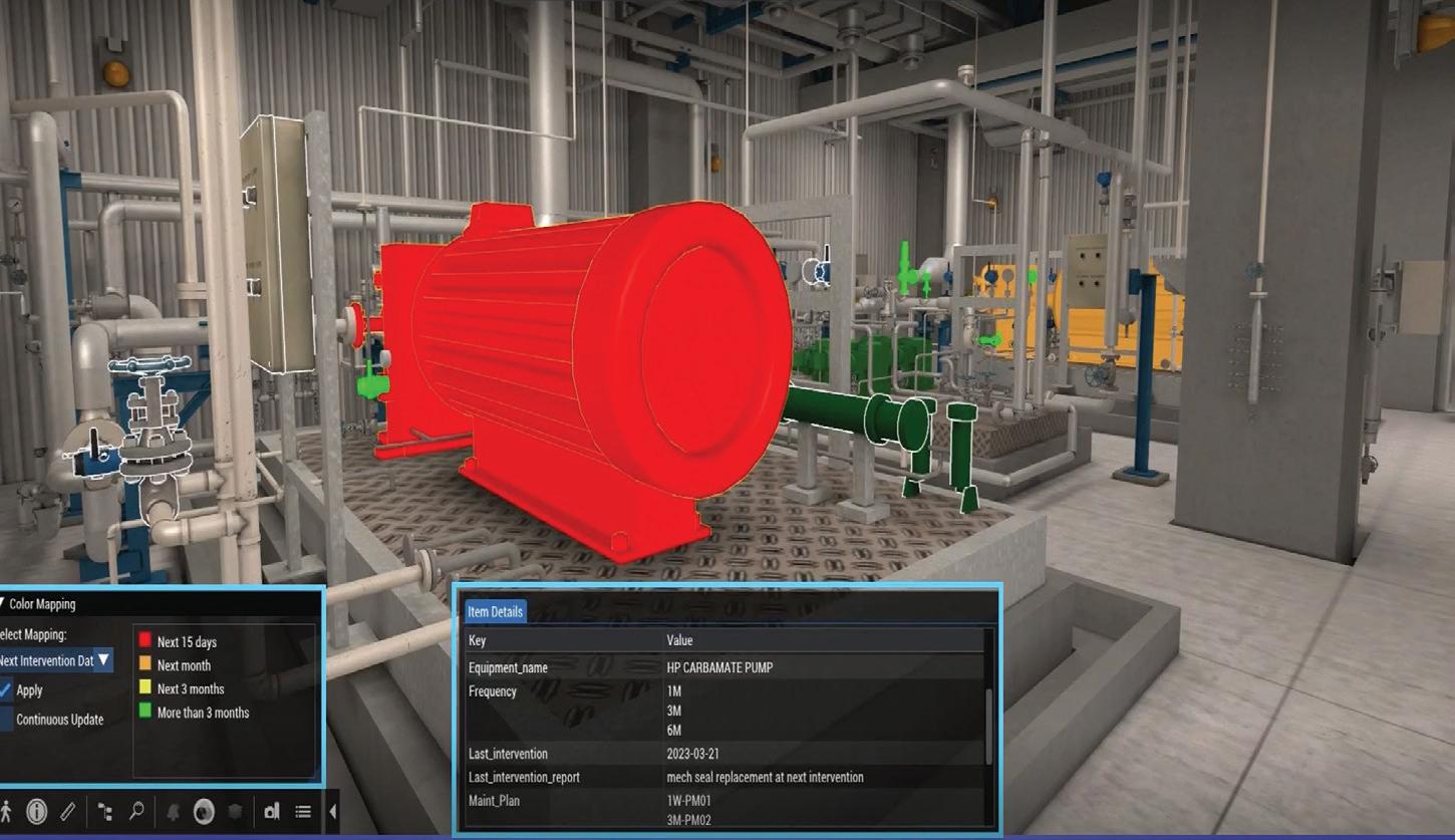
The interoperability with external systems (i.e. CMMS) allows easy linking of online and offline data to tagged objects in the rendered 3D model, displaying, for example, the maintenance activity plan scheduled for a certain asset. The maintenance dataset mirrored in the ITS guides the users to view information by business priority and due date.
26 | WORLD FERTILIZER | SEPTEMBER 2023
Figure 3. Functional correlation between process and asset digital twins.
Figure 4. Asset maintenance priorities shown within the rendered, immersive 3D model.
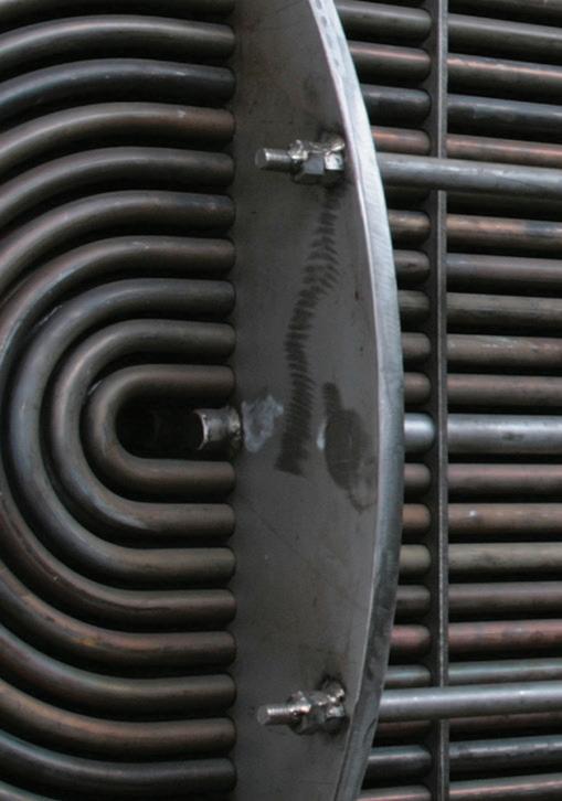
Exploring bimetallic tubing Exploring bimetallic tubing
Corrosion resistance is an essential requirement for applications that utilise nitric acid (HNO 3 ) in all concentrations. Standard austenitic steels of type ASTM 304L are often used in fertilizer and chemical industry manufacturing plants where nitric acid is present. Severe corrosion conditions are normally found in coolers/condensers, tail gas preheaters, and boiler feedwater heaters.
Aggressive conditions are found where condensation and evaporation take place, causing ASTM 304L type materials to corrode rapidly. Additionally, chloride-induced corrosion can occur when the cooling water contains chlorides. When higher corrosion resistance is needed, stainless steel can be used. 1 However, in some highly demanding process conditions, stainless steels might not offer sufficient corrosion resistance, leaving the end user with limited options to minimise
Tony Bugno, Alleima, USA, discusses how corrosion resistance can be maximised in nitric acid plants.
27
unexpected failures and costly repairs. When this is the case, users resort to upgrading whole equipment pieces to
zirconium due to its excellent corrosion resistance in this environment.
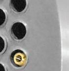
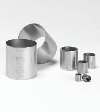
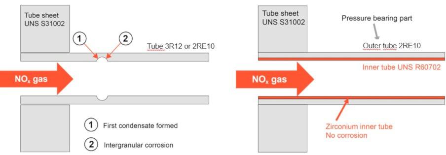
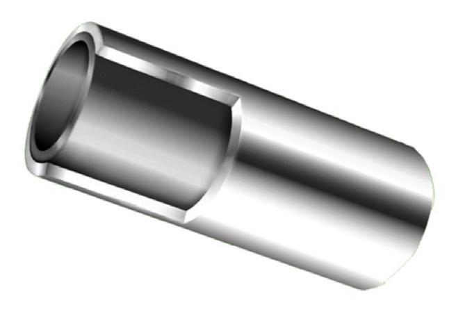
This article demonstrates how corrosion resistance can be maximised: Alleima has developed a bimetallic tube with an inner tube made of zirconium (Alleima Zr-702) and the outer tube made of Alleima® 2RE10 (UNS S31002) as shown in Figure 1. The zirconium inner tube is mechanically bonded to the outer tube. The inner liner prevents corrosion, while the outer tube provides strength and positive welding properties.
Corrosion resistance
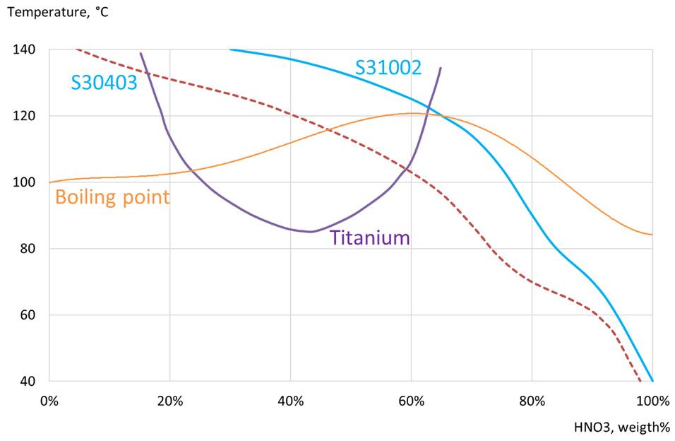
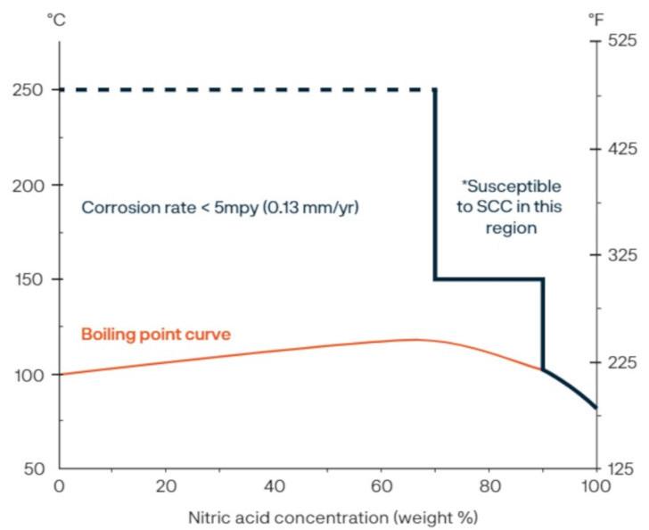
Alloy 304L is one of the most used stainless steels in wetted nitric-acid services. Figure 2 shows the iso-corrosion curves of stainless steels 304L and 2RE10, as well as titanium. The curves indicate a corrosion rate of 0.1 mm/year at the full range of HNO 3 concentrations and different temperatures. 2 If the traditional alloy 304L was chosen for a standard 68% nitric acid, this material would see a corrosion rate above the acceptable 0.1 mm/year at temperatures above 90°C. In comparison, 2RE10 would not see a similar corrosion rate until 115°C, demonstrating a higher corrosion performance in this typical nitric acid concentration. In Figure 3, the corrosion rate of zirconium is shown. Only at elevated temperatures and extreme concentration (>90%) or fuming nitric acid, does zirconium experience increased corrosion. 2,3
In applications where the nitric acid attack is the most severe, like coolers/condensers, tail gas preheaters, and boiler feedwater heaters, the zirconium inner tube provides exceptional corrosion resistance to extend the service life of the equipment. This is most prevalent in nitric acid condensers at the point of condensation. The zirconium inner tube is present to protect against the acid and high temperatures on the tube side of the condenser.
Figure 4 shows a comparison between using an austenitic stainless steel vs bimetallic tubing with an inner tube made of zirconium. At the point of condensation, the zirconium tubing provides the corrosion resistance to prevent the condensate, which is much more corrosive than the liquid bulk, from attacking the material and subsequently causing intergranular corrosion. 4
Ease of fabrication
One of the main challenges of using zirconium in equipment is the difficulty with fabrication.
Welding zirconium is challenging. Fabricators need to set forth significant time and cost to ensure the shielding and cleanliness meets the requirements to achieve a proper weld. If done incorrectly, the likelihood of weld failures increases, which will impact the equipments' performance and could result in leaks or other failures. Additionally, the cost of tube sheets in zirconium can be
28 | WORLD FERTILIZER | SEPTEMBER 2023
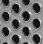
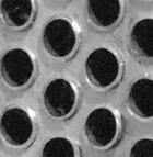
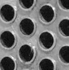
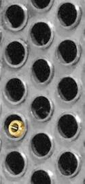
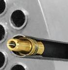
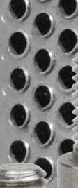
Figure 1. Bimetallic tubing (outer tubes - 2RE10/inner tube - zirconium).
Figure 2. Iso-corrosion diagram - nitric acid (HN03) – 0.1 mm/y.
Figure 3. Zirconium iso-corrosion diagram.
weight
Figure 4. Tubing comparing austenitic SS vs biemetallic in cooler/condenser.

extremely expensive in comparison to austenitic stainless steels.
The bimetallic tubing consisting of 2RE10 on the outer tube allows for an optimal tube to tube sheet welding process of a high alloy austenitic stainless steel. The low carbon and other impurities of this material provide good corrosion resistance for the shell side of the heat exchanger where the acid attack is not as extreme as the tube ID. 1
Alleima has performed trials to evaluate the best fabrication methods for bimetallic tubing. It was known that the inner zirconium tube would need to be removed in the welding zone to prevent melting of the zirconium. A trial was performed with removal of zirconium from the ends of the tubes at four different lengths (5 mm, 8 mm, 10 mm, 20 mm) and three different expansion rates (none, <2%, 3 - 5%).
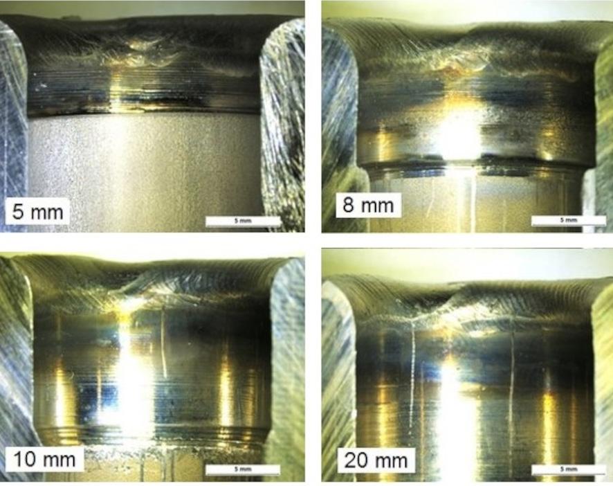
The tubing was welded to AISI type 304L plate with a thickness of 50 mm, and 310L welding wire was used in the automated TIG-welding process. The welding results from the trial can be seen in Figure 5. With a removal of 5 mm, the heat tint reaches the zirconium, and with the 8mm removal, the heat tint almost reaches the zirconium, however no oxidation was observed. For both the 10 mm and 20 mm removal distance, the results showed a safe distance of removal to prevent melting or oxidation. 4
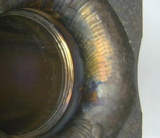

The results from the various expansion rates showed that the tubing was free from disbonding and a variation between the different rates was not apparent. These results indicate that it is possible to perform expansion up to 5% without disbonding or gapping between the two components. These trials were sampled for corrosion testing with the pieces cut so that each contained one tube including the weld and surrounding tube sheet. A modified Huey test (ASTM A262 pr. C) was performed in 65% HNO 3 for five 48-hour periods. Due to the complex and variation of materials in the samples, the corrosion was evaluated by visual inspection. The visual inspection of the corrosion samples showed no severe corrosion of the weld metal, heat affected zone (HAZ), bond zone, or on the zirconium. The worst corrosion was on the tube sheet on the cut and polished locations, which was expected due to the lower corrosion resistance of 304L. The zirconium was unaffected, and no indications were seen on the interface between the zirconium and stainless steel that would suggest a weak spot. Figures 6 and 7 show the results after corrosion testing. 4
Thermal conductivity
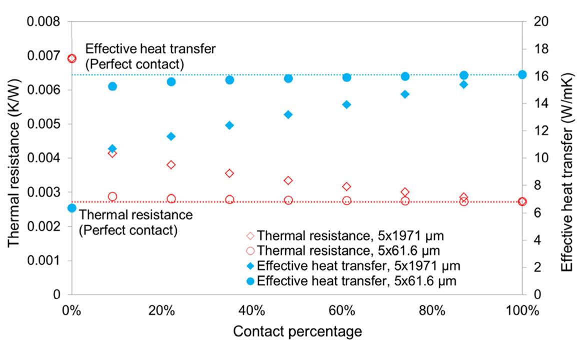
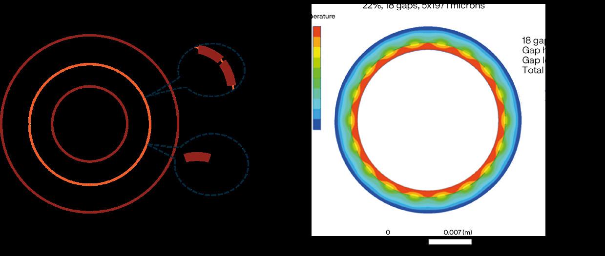
One concern that has been raised about the concept of bimetallic tubing is the heat transfer performance being compromised. Performed trials and finite element analysis modelling have been conducted to understand how heat transfer is affected. Figure 8 shows the model that was created to use small gaps
30 | WORLD FERTILIZER | SEPTEMBER 2023
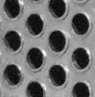
Figure 5. Weld trial results.
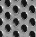
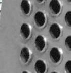
Figure 6 and 7. Weld and HAZ (left) and an inner surface and zirconium interface (right).
Figure 9. Heat transfer model results.
Figure 8. Heat transfer model - bimetallic tubing.
between the material surfaces of each different tube. In the hypothetical model, 18 bond points with a perfect surface to surface match were chosen and then in between those points, there was a gap length of up to 1971 ym where the middle of the gap had a height of 5 ym.4
In Figure 9, the results from the analysis are shown. Small gaps were added into the model to simulate delamination within the bond interface. The number of gaps, gap height, and gap length were simulated based on the modelling shown in Figure 8. Based on the simulations, the size of the gap is more important that the total contact. When the gap size is 5x61.6 µm, the heat transfer is marginally affected even as the total contact is drastically reduced. In the simulation, if the gap size is large with minimised contact, the heat transfer is seen to be impacted. Based on Alleima's examination of the tubes and product, it is considered unlikely that long gaps would exist with the process of the mechanical bond and stress between the two components. Small gaps may form due to surface roughness, but this should have a negligible impact on the relative heat transfer. As confirmation of this analysis, there are many applications of this exact same process produced with Alleima 2RE69 material as the outer tubing. These tubes have been used in the urea industry as stripper tubes where an evenly distributed heat transfer is important.4
Field experience
Besides there being multiple examples of bimetallic tubing being used in the urea industry, there are a few examples of its use in the nitric acid industry. The first installation in the US was in October of 2021 at a nitrogen fertilizer plant. The material has been running without issue since it was installed. The first plant turnaround and inspection also resulted in positive feedback from the Project and Turnaround Superintendent. No distortion or abnormalities were found with the tubes.
Conclusion
Bimetallic tubing is a solution designed for challenging and highly corrosive environments. When there are alternating wet/dry zones which leads to the presence of condensates, the corrosivity is much greater than the liquid nitric acid. The corrosion resistance of zirconium will prevent the start of intergranular corrosion that could form in stainless steels. Bimetallic tubing provides protection in a nitric acid cooler/condenser with acid on the tube side, while still providing an ease of fabrication with an austenitic tube to tubesheet welding process.
References
1. Alleima® 2RE10 Tube and pipe, seamless, Alleima, https://www. alleima.com/en/technical-center/material-datasheets/tube-andpipe-seamless/alleima-2re10/
2. Nitric acid production, Alleima, https://www.alleima.com/en/ products/tube-pipe-fittings-and-flanges/tubular-products/nitricacid-tubes/more-nitric-acid-with-less-risk/nitric-acid-producers/
3. Nitric Acid, The Chemical Company, https://thechemco. com/chemical/nitric-acid/?_vsrefdom=adwords&msclkid=a6 70efb0c94815e91b928b17977f21de&utm_source=bing&utm_ medium=cpc&utm_campaign=**LP%20DSA%20-%20All%20 Pages&utm_term=thechemco&utm_content=All%20Pages
4. D. GULLBERG, J. WALLIN, M. SENATORE, Bimetallic Tubes for Nitric Acid Applications, Nitrogen + Syngas 2016 International Conference (Berlin, 29 February – 3 March 2016)

Maximize SMR Performance with the Powerhouse Partnership of Blasch StaBloxTM and BD Energy Systems’ TOP Technology
With Blasch StaBlox Reformer Flue Gas Tunnel System and BD Energy Systems’ patented Tunnel Optimal Performance (TOP) Technology, you can expect:

Improved temperature uniformity that can significantly increase output with less risk to catalyst tubes
Reduced pressure drop saves energy

Significantly faster installation time can shorten outages
Available for immediate shipment to meet unexpected needs
580 Broadway | Albany, NY 12204 | 518-436-1263 | www.blaschceramics.com Visit Blasch and BD Energy Systems at these upcoming conferences: AIChE Safety in Ammonia, August 20-24 Scan the QR code to learn more about StaBloxTM
Getting the big picture with
vertical pumps 32
There are many benefits to using a vertical pump to transfer molten sulfur, sulfuric acid, and phosphoric acid. These types of pumps promote a safer operational environment as the vertical design eliminates pressurised seal area concerns, and the fluids pumped never touch the shaft stuffing box. However, there are considerations to be made before choosing a vertical chemical pump. To better understand the issues and concerns with vertical chemical pumps, it is important to explore the common concerns with the pump system. While each company extensively tests their pumps prior to shipment, many factors can impact their effectiveness. Such factors may include the type of fluid being pumped, temperature of the fluid, pump speed, operation schedule and maintenance/turnaround schedules. Regardless of the industry, vertical chemical pumps may experience complications as a result of unintentional vibration. The most common causes of pump vibration can be categorised as either mechanical or hydraulic. This article explores these two types of vibrations and their potential causes.
Marwan Karaki, Weir Minerals, USA, outlines the considerations to be made before choosing a vertical chemical pump, and explains the importance of proper selection, installation and maintenance.
33
Mechanical vibration
Pump alignment
It is very important for critical pump components to be aligned properly, particularly the shaft column, discharge pipe and volute. Before installing a pump and after all pump maintenance, a freedom of rotation test should be performed by suspending the pump vertically and manually turning the shaft to determine if any interference exists. After installation, the forces and moments at the flanged connections should be maintained within allowable margins. This eliminates any distortions that may cause rubbing of rotating parts where clearances are reduced or even eliminated.
Shaft straightness
The pump shaft must be as straight as possible at all times. Straightness must be checked at major overhauls or when the shaft assembly is rebuilt, even if there is no vibration. When mounted between centres in a lathe, the run-out at critical points such as the midpoint of shaft bearing assemblies and the impeller location should be within 0.002 in. total indicator runout (TIR).
Vibration frequency owing to the degree of shaft straightness ranges from one-time rotational speed to occasionally two to three times rotational speed. The amplitude is typically 150% of radial vibration in the axial plane.
Unbalanced impeller

The impeller is a major rotating mass in the pump that, if unbalanced, may result in high vibration. Impellers in both sulfur and acid environments may face rough conditions that lead to impeller imbalance. In sulfur environments, a foreign object might hit the impeller at high speed and result in damage that causes imbalance. In an acidic environment, an impeller may suffer from uneven areas of erosion or corrosion that result in imbalance and significant pump vibration. Selecting the appropriate material is critical to avoid such situations. In general, the vibration frequency in this instance
is equal to the rotational speed. Amplitude is greatest in the radial direction with a magnitude that is proportional to the amount of imbalance.
Bearing lubrication
Companies such as Lewis ensure that vertical chemical pumps are supplied with a shielded, double-row ball bearing of maximum capacity design intended to handle the applied hydraulic and mechanical loads properly. It is important to have the bearings replaced with OEM parts and to rigorously follow the pump manufacturer’s lubrication instructions. Proper installation of the bearing to both the shaft and the ball bearing housing is critical. The vibration frequency related to bearings is equal to the rotational speed times the number of rolling elements, and amplitude is proportional to the damage and wear of the bearing. In addition to this, amplitude increases with time.
Motor/driver
The motor/driver may generate some vibration caused by a worn bearing or an imbalanced rotor. When supplying motors, it is recommended to run the motor isolated from the pump to determine if there is any vibration caused by the motor. If the motor is new, it is highly recommended to request a routine test that will lead to testing and certification by the motor manufacturer.
Baseplates
Vertical pump cover plates and sole plates should be levelled and sufficiently robust. The components should be carefully examined after several years of service, since they have the tendency to lose their rigidity and distort. This therefore contributes to major pump vibrations. Misaligned plates prevent the pump from being properly rebuilt and aligned.
Pump motor alignment
In some cases, abnormal vibration and mechanical performance can be derived from a poor alignment between the pump and the motor. The misalignment of the coupling has no direct effect on the motor efficiency, however, correct alignment will ensure a smooth, efficient transmission of power from the motor to the pump. Misalignment takes place when the centrelines of the pump and the pump shaft are not in line with each other. Misalignment can cause the following symptoms: excessive vibration, increased bearing temperature, and shortened bearing or coupling life.
There are three types of misalignments to look for:
n Angular misalignment occurs where the motor is set at an angle to the pump. If both shafts are extended, they will cross each other.
n Parallel misalignment occurs where the motor and pump shafts are parallel to each other.
n Combination misalignment occurs where the pump and motor shaft suffer from an angular and parallel misalignment.
34 | WORLD FERTILIZER | SEPTEMBER 2023
Figure 1. Cavitation damage to an impeller.
Hydraulic vibration
Cavitation
Cavitation occurs when the net positive suction head required (NPSHr) is greater than the net positive suction head available (NPSHa). This causes an implosion of vapour bubbles formed in the liquid being pumped, usually on the low-pressure side of the impeller vanes. Cavitation can result in damage to the impeller by removing particles of metal from the surface with explosive force. This causes several problems, including discernible pump vibration. Most of the time, this condition takes place when there is a change in the system characteristics which alter the pump flow and head conditions for which the pump was originally selected.
Hydraulic imbalance
Suction conditions may exist that cause the flow distribution of liquid entering the pump impeller to be uneven. This can result from vortexing, improper clearances under or around the pump’s suction inlet or gas entrainment. The effect can be much the same as cavitation due to insufficient NPSHa.
Vibration monitoring
Vibration monitoring is fairly common today.
Accelerometer probes are usually installed on the pump’s upper thrust bearing or on a motor bearing. Measurements in at least two horizontal planes, located 90° apart, and in the vertical plane, can be made for vibration amplitude and frequency.
A log of these readings can be useful in both helping to discern the beginning of component wear before failure, and in identifying and remedying an installation problem. It is perhaps less important to focus on the magnitude and exact frequency of
vibration (unless it is extreme) than it is to pay attention to a change in the signature or pattern of the vibration spectrum. It is nearly impossible to completely eliminate all pump installation vibration.
ANSI/HI-9.6.4-2001 edition, 'Centrifugal and Vertical Pumps, Vibration Measurement and Allowable Values,' provides a guideline for the acceptable level of vibration depending on the pump structure. However, with knowledge of vibration sources, a good maintenance programme and installation procedures, and perhaps a monitoring system, pump vibration can be controlled and serious problems can be avoided.

While vertical chemical pumps are an excellent choice for transferring molten sulfur, sulfuric acid and phosphoric acid, important considerations should be made before choosing a vertical chemical pump. Unintentional mechanical or hydraulic vibrations may result in complications and affect the pump’s effectiveness. It is crucial to take preventative measures to ensure the proper alignment of critical pump components, maintain a straight shaft, have a balanced impeller, have OEM bearings with proper lubrication, and have good alignment between the motor and the pump.
Cavitation, a type of hydraulic vibration, can also occur when the NPSHr is greater than the NPHSa, leading to the implosion of vapour bubbles that can damage the pump’s impeller. Therefore, proper pump selection, installation, and maintenance are necessary to achieve the best performance and longevity of vertical chemical pumps.
 Reference
1. KARASSIK, I., Pump Handbook, 2nd edition, copyright 1986, McGraw-Hill Inc.
Reference
1. KARASSIK, I., Pump Handbook, 2nd edition, copyright 1986, McGraw-Hill Inc.
tubes@mst.mannesmann.com www.mannesmann-stainless-tubes.com
SYNGAS AMMONIA UREA NITRATES NITRIC ACID MELAMINE
Austenitic Stainless
Duplex
Nickel Alloys
Reaching full potential

36
Reducing energy usage is a growing concern for many industrial companies. Not only does it fit into wider decarbonisation strategies, but it can also significantly increase plant profitability. In any industry that handles fluids, pumps are a large source of energy consumption; it is estimated that pump systems account for 40% of industrial fluid system energy usage. With such a great portion of usage attributed to pumping systems, it is a key area where energy savings gains can be made.
A lot of discussion related to energy reduction is focused on buying new equipment with a higher energy efficiency rating. This is a factor worth considering when designing new units or systems. However, the gains available in improving efficiency within the pump design are usually dwarfed by the energy savings available by optimising the way the pump operates within its system.
It is estimated that 85% of pumps are not optimised to their systems, costing end users both efficiency and reliability.

Christen Mancini, Hydro Inc., USA, discusses how pump systems can be optimised to reach operational excellence and reduce environmental impact.
37
To achieve operational excellence and reduce environmental impact, assessing and improving systems is essential.
A second, and often overlooked, focus for reducing energy usage is ensuring that equipment maintains its design efficiency for as long as possible. This relates less to equipment design and more to tolerances, assembly and installation practices.
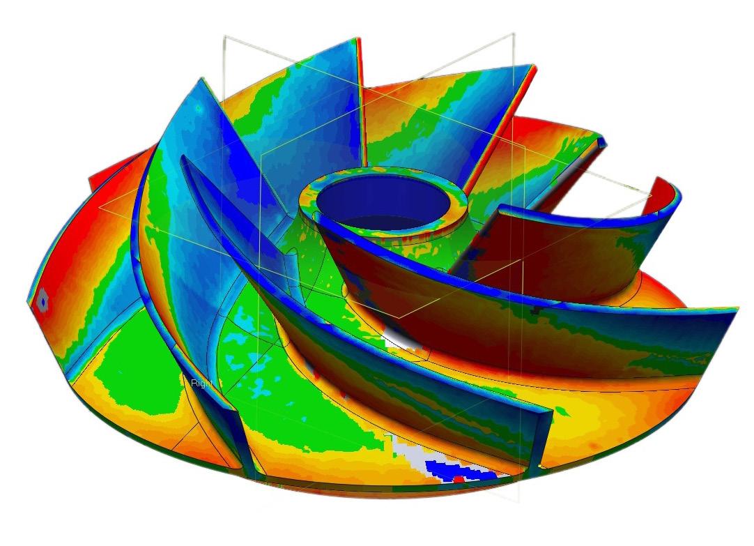
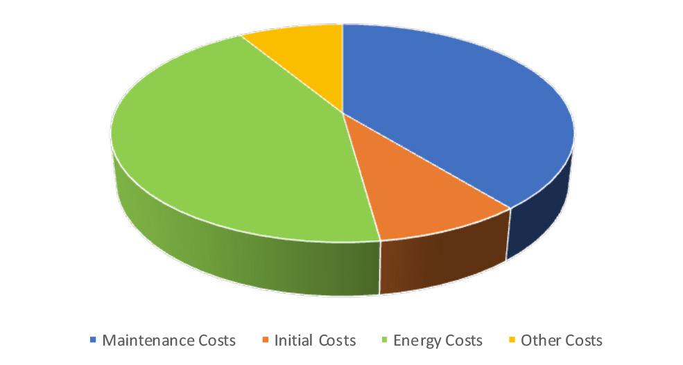
The need for system optimisation
With today’s technology, a pumping system can be optimised with less cost and a greater return on investment. Advancements in testing capabilities and analytical modelling help us to better understand and predict how fluid moves through a system, allowing us to identify more opportunities for improvement.
Most systems have too much pump operating, especially in older plants. When a pump is oversized, it puts more flow out into the unrestrained system than the process requires. To obtain the desired operating flow, a downstream valve needs to be throttled to increase system resistance and force the pump to operate back on its curve at the lower flow rate. The friction added to the system by the throttled valve wastes horsepower across the valve and reduces valve life. This wasted horsepower is energy that could be saved.
There are many reasons why a pump may be oversized for its system. Even in a new plant, design conservatism can result in an oversized pump being specified and delivered. This is usually the result of both the system designer and the pump manufacturer adding margin to their selections to guard against unforeseen factors that could compromise the equipment’s ability to effectively deliver the required system flow.
For older plants, increases in system demand from the original system design can also result in a non-optimised system. While the installed equipment may be capable of delivering the increased flow, this change can negatively affect both its efficiency and its reliability. It is not uncommon to see a system that originally operated with two 100% pumps undergo a system flow increase that requires the operation of both pumps in parallel. In this scenario, it is highly likely that the change in operation will result in lower efficiency and a degradation of performance and life. As shown in Figure 1, changing operations from one 100% pump to two pumps in parallel forces both pumps to operate at a point farther back on their performance curve. In the illustrated case, the x on the right marks the original flow and efficiency and the x on the left marks the new flow and efficiency under parallel operation. To deliver the specified flow, friction must be added to the system; this changes the system curve shape so that it intersects with the two-pump curve at the required flow rate. The throttled head is shown in Figure 1 as the red portion of the uprated flow demand line.
The costs in both wasted energy and decreased mean-time-between-repairs caused by non-optimal operation are not always considered and can be quite large. With the potential drawbacks of making system changes taken into consideration, it is important to take a closer look at pump operation every time a change to system demand is proposed. This evaluation should determine not only if the existing pumps can meet the new demand, but if they should operate at this new flow rate without modification.
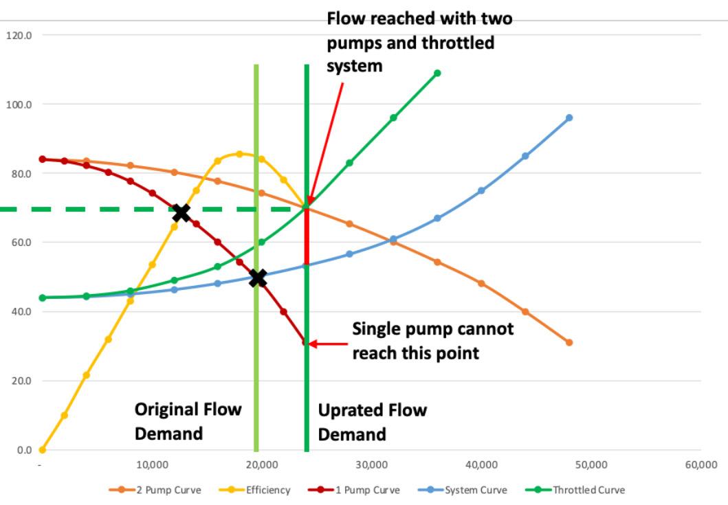
How system optimisation is achieved
Fortunately, optimising the pump to its system is an achievable goal. The first step in optimising a system is understanding its weaknesses and identifying the main
38 | WORLD FERTILIZER | SEPTEMBER 2023
Figure 1. Changing from one pump operation to two pump operation.
Figure 2. Typical lifecycle costs.
Figure 3. Example of impeller study using computational fluid dynamics.
PATHWAY BLUE
MAKE THE ENERGY TRANSITION YOUR BUSINESS.
Meet the fuel of the future today. Produce blue ammonia at the highest capacity with the lowest possible levelized cost. Decarbonize at mega scale while increasing the value of your ammonia product. Integrate blue ammonia solutions today to meet the demand of tomorrow.
Blue Ammonia. Tomorrow’s fuel. Ready today.

NH3
areas of energy savings and cost savings potential. Field testing the equipment and performing a system survey supports better understanding of the actual hydraulic and mechanical performance. Data taken during field testing can later be used when troubleshooting problems and engineering system modifications. Advanced software that supports system analysis can also be useful at this stage to verify the accuracy of the system curve provided at plant construction, predict how changing pipe roughness of aged systems may have altered resistance, and identify areas outside of the pump where energy can be optimised.
Once pump operation and system needs are clearly understood, actions can be taken to alter pump performance to meet the actual system demand. In most cases, a pump can be optimised by using the affinity laws. The affinity laws state that a change in flow is directly proportional to a change in pump speed or impeller outside diameter, the head is directly proportional to the square of the speed or diameter change, and horsepower is directly proportional to the cube of the speed or diameter change:
to the system decreases. System resistance needs to be decreased to allow the pump to operate at a higher flow rate; the increased flow is needed to make up for the recirculated fluid and deliver the required total output.
Internal recirculation is controlled by close clearance areas, such as wear rings or bushings, that separate neighbouring regions of differential pressure. Maintaining the design clearance of these components is essential for limiting internal recirculation. The greatest influences on clearance degradation are large tolerances and poor assembly practices.
Stringent tolerances are critical for maintaining efficiency because rotating and stationary components that are not on a common centreline will wear at an accelerated rate. To ensure centreline compatibility, stationary components must have concentric, circular bores and registers, and bolting faces must be perpendicular to these bores. Rotor TIR must be limited and adjoining shafts must be in parallel and angular alignment. Fit-ups cannot be excessive to limit any offset of the component inside its fit. Multistage elements must be assembled vertically; if this is not possible, measures must be taken to avoid a stack up of fit tolerances.
For systems with a single required operating point, a change in diameter is usually made because it requires the least amount of investment. This modification should be made with an experienced engineering partner, as there are additional considerations that need to be made based on the specific speed of the pump to determine the final diameter dimension. Computational fluid dynamics (CFD) can be used to support this determination. Testing modified pumps in a laboratory environment is recommended to both verify performance and produce a new certified performance curve.
For systems with multiple operating points, a variable frequency drive (VFD) can be employed to achieve operation at peak efficiency for any required flow. Beyond the higher investment cost, using a VFD carries the risk that one of the speeds within the operating range may excite a natural frequency in the rotor or stator. For this reason, an engineering study is recommended when considering upgrading to a VFD so that all resonant modes that may be excited within the proposed speed range are identified.
A third option is to provide a custom impeller design developed specifically for the application. Designing custom hydraulics contrasts with the much more common practice of choosing the ‘best fit’ hydraulics from a range of existing designs. As such, custom designs can lead to a more accurate match of system needs and a higher peak efficiency.
Maintaining efficiency
After equipment is optimised to its system, the next consideration is maintaining design efficiency after installation. Reductions in efficiency over the life of equipment is related to increased internal recirculation. As internal recirculation increases, the total fluid discharged
Outside of some small design choices, such as upgraded wear ring materials that allow for closer clearances, the above is not a function of pump design. Attention to detail, strict acceptance criteria, and experienced personnel are all part of the blocking and tackling that must be done to maintain efficiency. This requires choosing a qualified partner for equipment refurbishment and training internal maintenance crews to best-in-class standards. Understanding that a low first cost is dwarfed by the unavailability, maintenance, and energy costs associated with the 'cheap fix' is a critical first step for reducing total cost of equipment ownership.
The last key thing to consider when implementing a system modification is educating the people who interact with the pump system. Optimising a system and then operating it in a way that compromises the investment made will negate any progress being made. Providing an understanding of how pump operation effects reliability and efficiency supports more informed operation and maintenance of the equipment.
Occasions where changes are a win-win situation are rare, but system optimisation is one of them. Optimising pumping systems contributes to the sustainability of the environment and the long-term profitability of the site enacting the change. Part of the positive environmental impact can be measured in the reduction of energy consumption by the system. Other impacts are less directly measurable, but just as real. Extended maintenance cycles result in reductions of raw material usage and reduction in greenhouse gas emissions related to the transport of those materials. Improved mechanical performance reduces the risk of seal failure that can release process fluid to the environment; it also reduces the risks for catastrophic failures that jeopardise worker safety. Best of all, reductions in the cost of equipment operation quickly recover the costs for the initial modification, making this an endeavour that pays for itself.
40 | WORLD FERTILIZER | SEPTEMBER 2023
Brian Rudary, Swagelok Company, USA, discusses the importance of following design practices in order to ensure more effective maintenance and smoother running of critical operations in fertilizer processing plants.
In the 1980s, mechanical seals became the dominant sealing technology in a variety of processing plant environments. In response, the American Petroleum Institute (API) established a standing committee charged with creating standards for these components. By 1994, the committee had issued the first edition of its standard, 'API 682 Shaft Sealing
Systems for Centrifugal and Rotary Pumps.' It announced the development with the following statement: 1
"This standard is designed to default to the equipment types most commonly supplied that have a high probability of meeting the objective of at least three years of uninterrupted service while complying with emissions regulations."
Playing by the rules

41
A close reading of the standard reveals recommendations that processing plants should default to proven technology unless otherwise specified. Now in its fourth edition, API 682 is still considered the correct standard for mechanical seals and their support systems in a multitude of processing plant situations.
Though most of the standard focuses on mechanical seals, it is important to understand that it also includes significant discussion around seal support systems. Ensuring the peak performance of seal and pump systems relies on the proper interplay between the physical seal and its supports (Figure 1). Therefore, working with a seal support manufacturer that adheres to the fourth edition API 682 rules is essential.
In addition, it is critical for processing plant operators to understand the best practices involved in marrying seals and supports, and why implementing the fourth edition API 682 standard on the ground is so important. Following these rules may improve the reliability and safety of processing plants while also reducing costs.
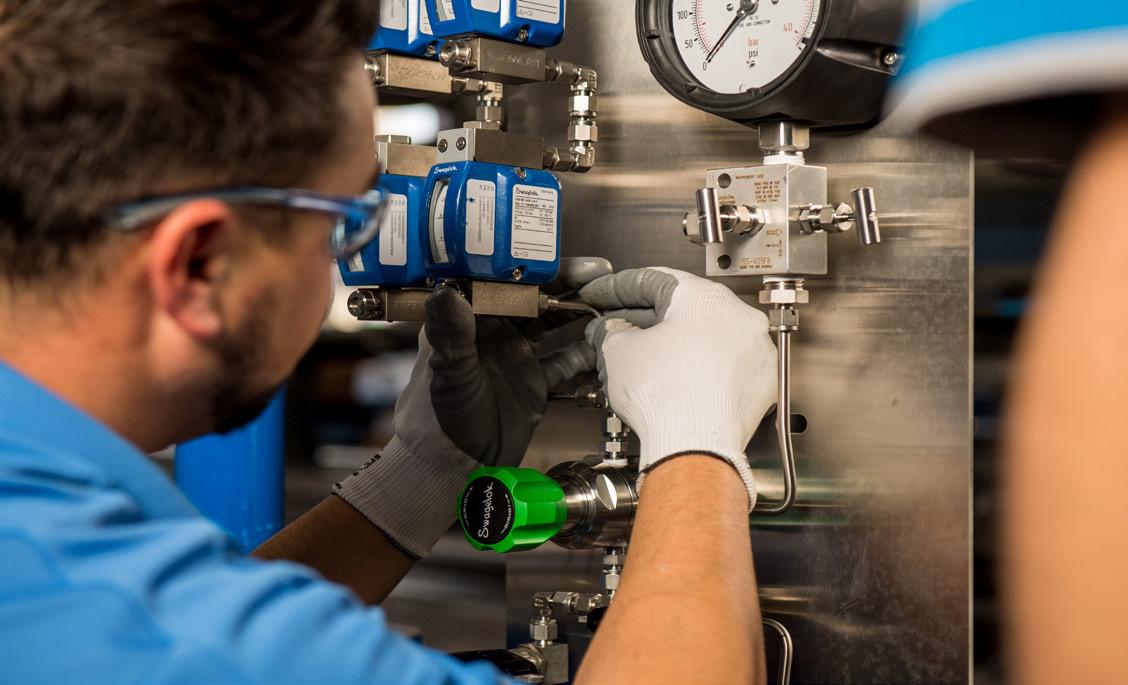
Reducing potential leak points
Threaded connections increase the possibility of leaks, which is why the fourth edition API 682 suggests reducing the overall number of connections within systems. It does not matter if the system is comprised of welded pipe or tubing – each connection is a potential leak point, increasing the potential danger for employees and the environment. If the seal support system is leaking near the pumps, it can cause damage to the equipment or increase downtime.
Historically, pipe was the material of choice in most seal support systems. In recent years, however, tubing has replaced pipe as the preferred material. Seal manufacturers, end users, and pump original equipment manufacturers (OEMs) have realised that tubing is a better solution because it contains fewer connections and has been used successfully in other critical applications across industries.
The fourth edition API 682 specifies tubing and pipe almost interchangeably when it comes to specifying seal support system connections, but some operators have not adapted to the new rules. 2 More education is necessary to urge plant operators to change their practices and move away from hard pipes in favour of tubing.
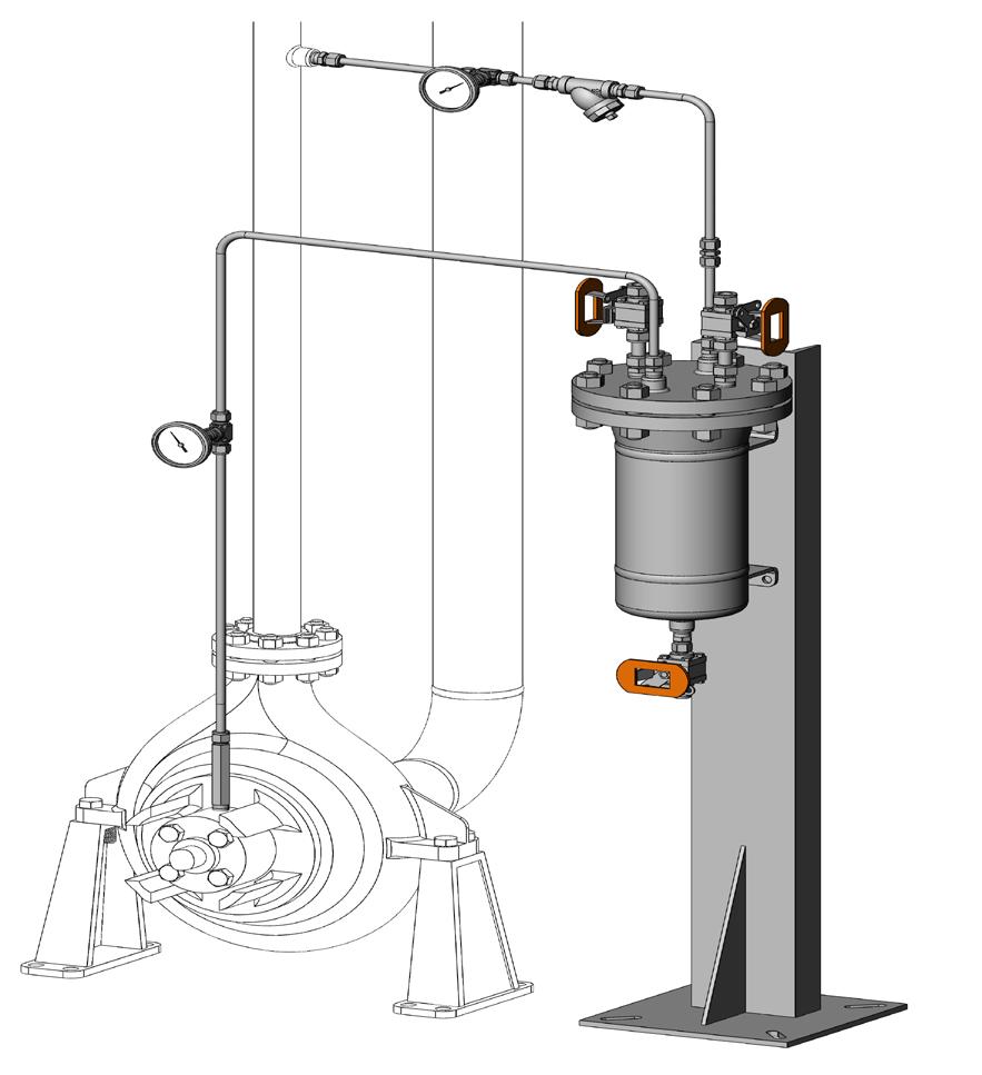
Using tubing instead of pipe reduces the number of connections by bending lines and using appropriate adapter fittings. The connection points are often limited to the seal and the sealing system (Figure 2). Since tubing is annealed, bending the tubing hardens the metal, increasing the strength of the tube at the bend. Additionally, connector technology continues to improve. Flange adapters and extended male connectors make even fewer connections possible from threaded ports on the seal and seal pots. These
eliminate
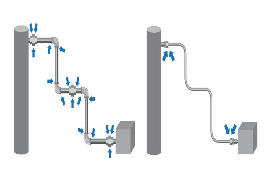
42 | WORLD FERTILIZER | SEPTEMBER 2023
innovative connectors
Figure 1. Not all seal support system components are created equal. It is crucial to use high quality components like those in this API Plan 22 cooled flush system with a strainer. Using high quality components will maximise uptime and minimise maintenance.
Figure 2. One way to lower the risk of leaks is minimising connection points. One option is the transition from a threaded pipe assembly (left) to a tubing run (right), which lowers the number of connections from 17 in the piping setup to just four with the tubing run.
Figure 3. Putting seal support systems on panels makes it easier for technicians to identify components, ensure they are working correctly, and maintain them seamlessly.
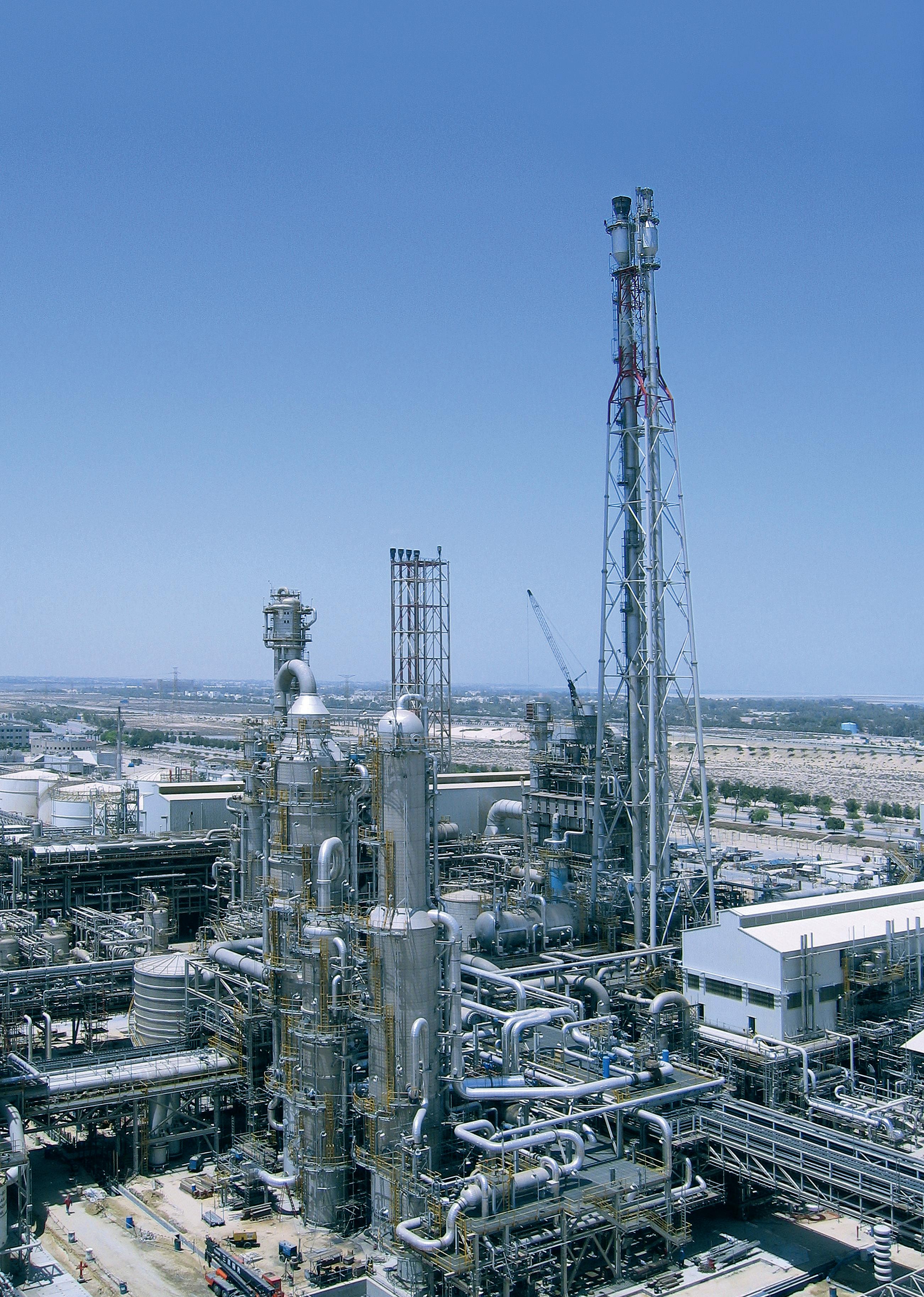
unnecessary fittings. Using tubing instead of pipe also lowers the maintenance, repair, and operational (MRO)
costs involved with pumps, seals, and support systems. When maintenance is necessary around pumps, tubing eliminates costly on-site welding associated with traditional pipes. Finally, tubing is easier to install, which reduces potential downtime.
Making operations and maintenance simpler
Without seal support systems, a variety of issues may be introduced to seals and pumps. This may include incorrect operation, premature failure, inadequate performance, and an overall higher cost of ownership. The importance of seal support systems means regular visual inspections are critical. Simplifying the process of visual inspection improves system reliability and safety. When seal support systems are being designed, these best practice design principles allow the system and its performance to be maximised.
System function and design
Mechanical seals commonly fail because of the damage done by stopping and starting pumps regularly, which can be the result of improper seal support system operation. Designing the seal support system to make it easier to operate can eliminate some common errors that occur when pumps are commissioned.
Plan 32, a detailed section of the fourth edition API 682, provides guidance on how to install multiple instruments on piping or tubing. If the system is designed according to these rules, it will work, but it will provide no information to operators about how the system operates, which information they should concentrate on, or why they should concentrate on it. For example, operators should bend down to read the instrument information on a pump if it is near the pump seal. It is important to make sure trouble signals will be spotted early, so it is incumbent on the designer to minimise obstacles for operators. The smallest obstacle can lead to reduced reliability. Systems should be intuitive to ensure they will consistently operate at peak performance (Figure 3).
For example, putting a Plan 32 piping system on a panel allows for easier identification and operation (Figure 4), which offers the following advantages:
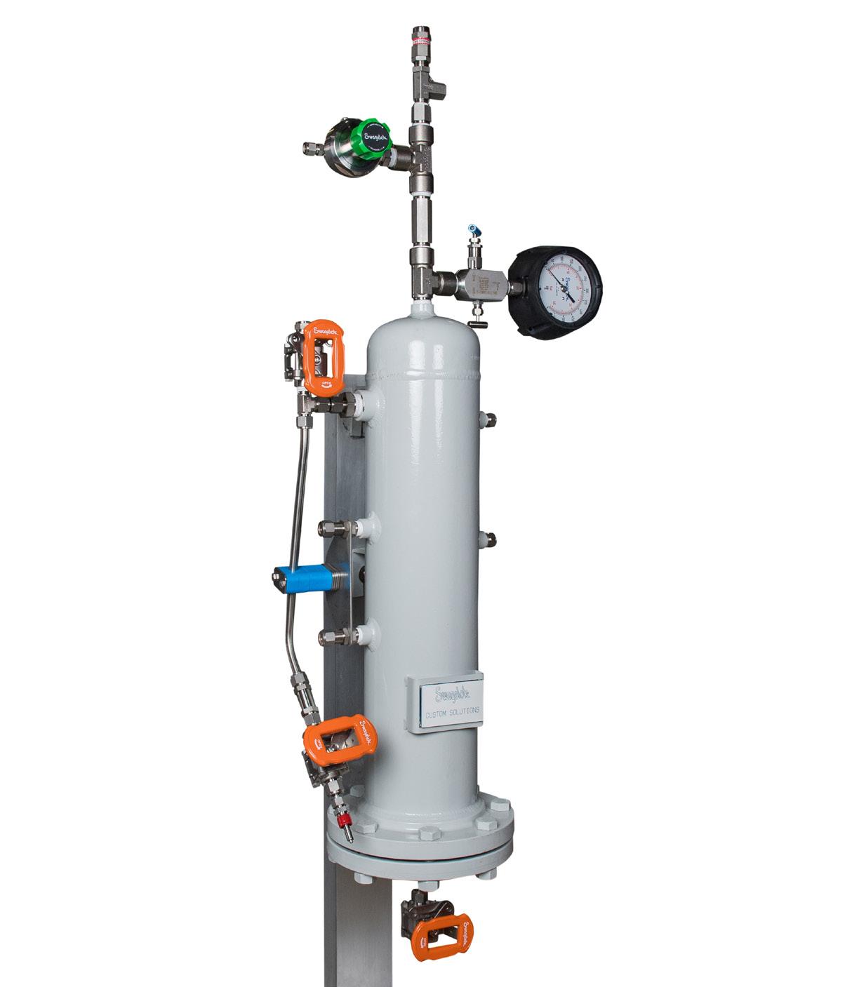
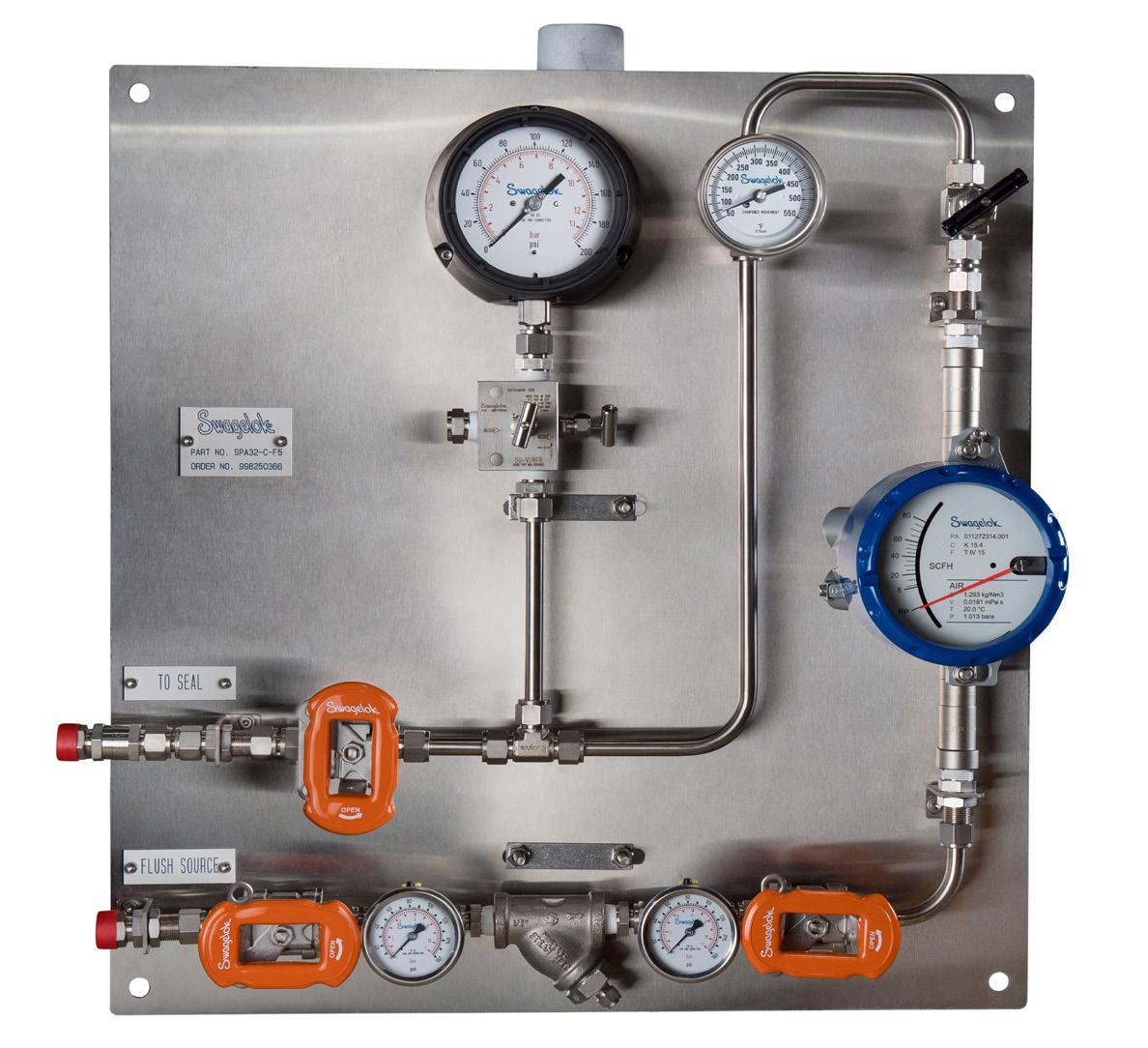
n Plan 32 now looks like a distinct system. Instead of only having components located on a pipe or tube run, they are laid out on a panel on which the flow path can be identified, and all instruments are available at eye level.
n The fourth edition API 682 supports these design considerations, stating: “All controls and instruments shall be located and arranged to permit easy visibility by the operators, as well as accessibility for tests, adjustments, and maintenance.” 2
44 | WORLD FERTILIZER | SEPTEMBER 2023
Figure 4. Arranging piping, such as a Plan 32, on a panel incorporates two critical design principles. It allows operators to easily identify system components and processes and also streamlines operations.
Figure 5. Block and bleed configurations on gauges are encouraged by the fourth edition API 682. This arrangement allows for easy gauge replacements without shutting down the entire pump and support system.
n Panels can include part numbering information, flow path indication, and operator instructions. These improvements help ensure safe and reliable startup and shutdown of pumps and seal support systems.
Ease of maintenance
Not only should proper operation of seal support systems be considered, but designers should also take ease of maintenance into account. Seal support systems are complex, containing many components that may need to be serviced. Flowmeters, strainers, and other visual instruments are just a few of the components that may require maintenance on a regular basis. It is important to implement a preventive maintenance (PM) plan for these systems, and that plan must be easy for operators to understand and safe for them to execute.
One example of equipment that must be conveniently positioned and available for blowdown is the strainer. Making sure the strainers are easily accessible means PM is more likely to be performed regularly so the components can achieve their desired intent.
In addition, fourth edition API 682 suggests block-bleed configurations for all system gauges (Figure 5). Without this precautionary element, gauges are likely to fail and leave operators without crucial information to prevent the problem from occurring again. Instead, the information will not become available until the pump and support system are decommissioned and the gauge is replaced.
Finally, different tubing connections and design options exist to ensure each serviceable component on a seal support can be easily removed and replaced without shutting down the system completely. For seal pots, the fourth edition API 682 stipulates that: "unless otherwise specified, systems that require the use of a ladder or step or that require climbing on the baseplate or piping are not acceptable”. 2
Many plants have older seal pots with just a pipe plug at the top. Having operators climb a ladder to top off the pot can expose them to process vapours and is a generally unsafe practice. Designing Plan 52s or Plan 53s with fill systems is a simple design consideration and best practice that promotes safe maintenance.
Constructing better seal support systems
Employing best practice design principles for mechanical seal support systems improves reliability and lowers costs. Better results within systems can be achieved by taking these steps:
n Consider using tubing instead of welded pipe to reduce installation and maintenance costs. This will promote reliability through the reduction of potential leak points.

n Keep pumps online to fix minor instrumentation issues or fill seal pots. Locating these systems on panels with proper labelling and designing for easy maintenance reduces the chance of operator error which can damage seals.
Conclusion
All processing plants that use rotating equipment should be concerned about the cost of replacing failed seals. Using fourth edition API 682 as a guide, safer and more reliable systems can be designed.
Fortunately, systems never have to be designed alone. Working with a reliable seal support systems supplier allows experts to be called on to design systems to meet specific needs. The goal is to find a partner who offers configurable, local, and reliable systems that help reduce costs, save time, and improve the safety of rotating equipment. Fertilizer processing plants will run more smoothly than ever with the proper seal support systems in place.
References
1. API Standard 682, First Edition, 1994, “Shaft Sealing Systems for Centrifugal and Rotary Pumps,” American Petroleum Institute , Washington, D.C.
2. API Standard 682, Fourth Edition, 2014, “Shaft Sealing Systems for Centrifugal and Rotary Pumps,” American Petroleum Institute , Washington, D.C.
vessels and heat exchangers.
BORSIG solutions for the ammonia industry.

→ waste heat recovery systems
→ waste heat boilers for ammonia, methanol
a nd hydrogren plants
→ synloop waste heat boilers for ammonia plants
→ synthesis gas coolers
d ownstream of partial oxidation of oil or natural gas
To learn more about our products please visit www.borsig.de/pro or contact BORSIG Process Heat Exchanger GmbH

E-mail: info.bphe@borsig.de Pressure
Sulphur + Sulphuric Acid 2023 Conference & Exhibition


November 6-8, 2023 • Sheraton New Orleans, Louisiana
Understand the key market and technical developments shaping the industry


RETURNINGTO THE UNITED STATES

Now in it’s 39th year, the event continues to be an essential annual forum for the global sulphur and acid community to learn, connect and do business.


You can expect an expanded market outlooks agenda, including expert insights from CRU’s analysis teams on major supply and demand markets, including sulphur, sulphuric acid and phosphates, plus additional industry updates from key players from across the supply chain.


Sponsors:


Supporters:
For more information or to book your place, please visit: www.sulphurconference.com
Minerals

39th Oil | Gas | Fertilizers | Metallurgy | Industrial
Register Today
S C A L I N G D O W N
S C A L I N G D O W N

Rajesh Raitani and Steven Paulson, Nalco, USA, provide an overview of phosphoric acid heat exchanger scaling and its impact on productivity in the fertilizer industry.
Scale formation is a persistent concern across a wide range of mineral processing operations, significantly influencing productivity and the overall cost of operations. In phosphate and phosphoric acid production, a variety of scale deposits can negatively impact productivity and efficiency. Hard and tenacious scale can form in:
n Flotation cells.
n Digestion tanks.
n Vacuum filtration sections.
n Phosphoric acid clarifiers and storage tanks.
n Evaporators and heat exchangers.
n Transfer lines for rock slurry and acid and gypsum slurry lines.
Fertilizer manufacturing plants with integrated beneficiation, utilities and water recovery, and treatment units, suffer from additional scale deposits on equipment and within material transfer lines. Plant process engineers are challenged with the cleaning schedules of numerous assets while maintaining production and quality targets. Operation shutdowns to clean the scale deposits and deteriorating production rate between cleaning times are lost opportunities, which can be realised if scale can be prevented.
This article provides an overview of phosphoric acid heat exchanger scaling and its impact on operational productivity through a series of case studies.
Scale and its impact on phosphoric acid production
Scale is formed in phosphate fertilizer plants due to mineral deposition in vessels, transfer lines, and equipment as a result of precipitation when saturation occurs in the process solution. Changes in temperature, concentration of dissolved species, pH, pressure, turbulence, and flow rates are the most common drivers of scale formation. Phosphoric acid is produced by digesting phosphate rock with an acid (generally concentrated sulfuric acid). Both phosphate and non-phosphate minerals react with the acid, resulting in a variety of chemical species in solution. These solutes in the weak phosphoric acid interact with each other to form a myriad of minerals with varying solubilities in water. A typical composition of weak phosphoric acid produced in a fertilizer plant is presented in Table 1.
In a phosphoric acid plant, weak phosphoric acid with 28% P2O5 is usually concentrated to 52% P2O5 or above, in a single or multi-stage evaporation process (Figure 1).
Weak phosphoric acid is fed to the evaporator which is primarily comprised of concentrated acid being recirculated through the heat exchanger, a recirculation pump, and the evaporator under vacuum. Evaporation of acid not only increases the concentration of phosphoric acid, but also leads to its cooling from evaporation under vacuum, putting thermal and concentration stress on the solution in recirculation. This results in precipitation of
47
minerals and scaling on the heat transfer surface of heat exchanger tubes, evaporator walls and other parts of the acid concentration unit. Scaling in the concentration section causes several issues:
n Loss of evaporator efficiency throughout the entire production campaign.
Aluminium (Al): 410 mg/kg
Barium (Ba): >0.8mg/kg
Boron (B): 9 mg/kg
Cadmium: (Cd): 1.3 mg/kg
Calcium (Ca): 280 mg/kg
Phosphorus (P): 120 000 mg/kg
Potassium (K): 130 mg/kg
Silicon (Si): 2500 mg/kg
Silica (SiO2): 5300 mg/kg
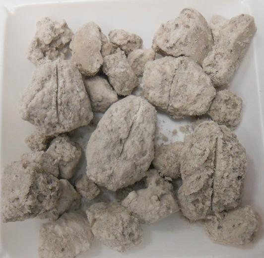
Sodium (Na): 110 mg/kg
Chromium (Cr): 45 mg/kg Strontium (Sr): <0.8 mg/kg
Copper (Cu): 9 mg/kg Vanadium (V): 38 mg/kg
Iron (Fe): 740 mg/kg Zinc (Zn): 30 mg/kg
Lead (Pb): <16 mg/kg Fluoride (F): 16 000 mg/kg
Lithium (Li): 1.6 mg/kg Chloride (Cl): <1900 mg/kg
Magnesium (Mg): 6700 mg/kg Nitrite (NO2): <1900 mg/kg
Manganese (Mn): 15.6 mg/kg Bromide (Br) <1900 mg/kg
Molybdenum (Mo): <6 mg/kg Nitrate (NO3) <1900 mg/kg
Nickel (Ni): 4 mg/kg Sulfate (SO4) 22 000 mg/kg
n Operational shutdowns for cleaning (time that could have been used for production).
n Increased cleaning expense.
n Risk to employee safety and assets from pressurised water or chemical cleaning, which can injure employees and damage equipment.
As a result, inhibiting scale formation in the process would reduce the losses and dangers connected with scale formation and cleaning.
Scale formation in mineral processing operations typically occurs in three distinct stages: nucleation, crystal growth, and deposition. If one or more of these mechanisms can be impacted or disrupted, then scale formation can be reduced or even eliminated. A range of scale inhibitors has been formulated by Nalco Water to function under a wide range of chemical and physical conditions. These products reduce scale formation by disrupting nucleation and crystal growth, as well as dispersing crystals that have formed in solution, thereby reducing attachment to equipment and heat transfer surfaces.
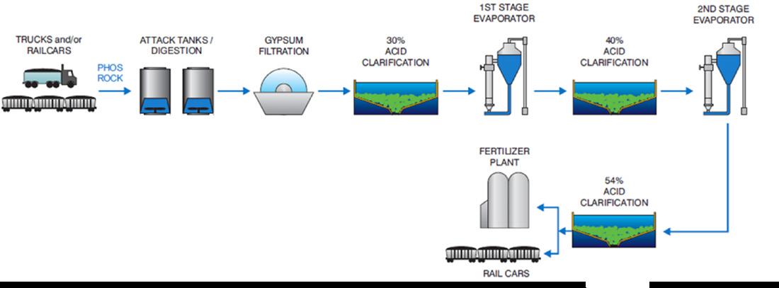
Approach to scale inhibition
A comprehensive approach to assessing scaling issues in phosphoric acid operations should be taken to develop an optimised solution. This entails detailed understanding of the problem and quantifying its impact on the process, broadening the scope of discovery to include beneficiation, reaction, filtration, clarification and storage, phosphoric acid concentration, transportation, and fertilizer production.
Using information obtained during the comprehensive discovery process along with chemical analysis of the scale and solution samples, technical specialists can determine the main factors impacting scale formation. Following that, multiple scenarios can be developed based on existing conditions and potential enhancements to the evaporator section from the scale inhibition programme, and potential bottlenecks – both upstream and downstream – and can be identified. Cost-benefit evaluations for these scenarios can then be pinpointed. This benchmarking exercise with chemistry diagnostics, is utilised to recommend the best available solution for scale control for exponential return on investment (eROI).
Programme for scale inhibition
Nalco Water provides a SCALE-GUARD programme for evaporator scale-inhibition in phosphoric acid plants which provides increased production cycle length, reduced cleaning time and frequency, and easier and safer heat exchanger cleaning, resulting in increased productivity. The scale inhibitor formulation dose requirements and application points vary from plant to plant and depend on scaling intensity, chemistry, and desired outcomes. The following are case studies involving use of the programme at various customer locations:
Cleaning time and productivity improvement
A North African fertilizer plant suffered from intense scaling in the heat exchanger tubes in a phosphoric acid plant (Figure 2). Tenacious, hard-to-clean scale in the tubes
48 | WORLD FERTILIZER | SEPTEMBER 2023
Figure 1. A simplified flow sheet for phosphoric acid production.
Table 1. A typical composition of weak phosphoric acid produced in a fertilizer plant.
Figure 2. Plugged heat exchanger tubes and tenacious, hard-to-clean scale.
Figure 3. Heat exchanger scale transformation with use of the scale inhibitor.
A global industry requires a global publication


Register at www.worldfertilizer.com
Global publication
forced operations to shut the plant down for high-pressure water jet cleaning, resulting in production downtime, cleaning expenses, and exposure to unsafe conditions.
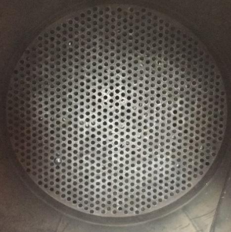
A mineralogical analysis of scale indicated anhydrite, malladrite and magnesium aluminum fluoride hydrate as major minerals present. There was a need to find a solution as the customers requested a reduction in cleaning time and productivity improvement.

As a result, Nalco Water implemented the SCALE-GUARD programme at the site after a detailed operations survey and chemistry diagnostics. After one month of trial and optimisation, and continued use of the solution at a 150 ppm dose in weak phosphoric acid, the number of plugged
tubes were reduced from 125 to 25 with the use of a scale-inhibitor. The cleaning time was thereby reduced from 10 hr to 2 hr. The cleaning job, which was earlier performed by three operators working for 12 hr per plant, with the use of the scale-inhibitor, now could be accomplished by one operator in 2 hr per plant. Change in scale morphology upon use of the scale-inhibitor, facilitated faster and easier cleaning (Figure 3). The scale-inhibitor enabled added production of 28 800 t P2O5/yr (3.3% increase) due to a cleaner heat exchanger tubes and faster cleaning.
Production cycle extension and productivity improvement
A major phosphoric acid manufacturing plant in the Middle East lost significant production time due to scale formation in heat exchanger tubes. In a multi-line operation, where the lost production opportunity was multiplied, production campaigns lasted, on average, 15 days. Moreover, high-pressure water jet cleaning was deployed every month to clean the hard scale formed within the heat exchanger tubes.
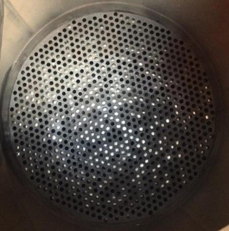
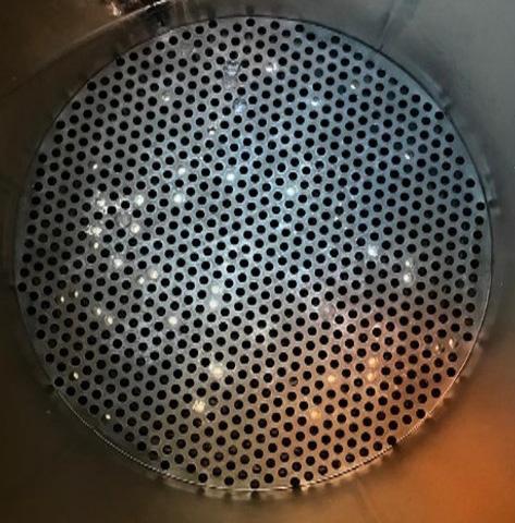
A mineralogical analysis of scale indicated gypsum, anhydrite and malladrite as major minerals present. Again, there was a need to find a solution as customers requested production cycle extension and productivity improvement. Following a meticulous operations survey and chemistry diagnostics, Nalco Water conducted an extensive industrial scale trial (six months) with the SCALE-GUARD programme at the site.
The outcome was that multiple heat exchangers were trialled and dosed with the same phosphoric acid feed, and the results were compared to an untreated evaporator. The continued use of the solution at a dose of 200 ppm in weak phosphoric acid increased the average production cycle duration from 18 to 30 days, with the longest production cycle lasting 52 days. Phosphoric acid production from the treated evaporator was 8.4% higher than the untreated evaporator during the six month trial period. Average production per operating day also increased by 5.7% indicating a cleaner heat exchanger when using Nalco's scale inhibitor. Because of the change in morphology, the scale was also found to be easier to clean.
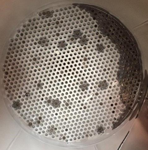
Conclusion
Scaling in a phosphoric acid plant's heat exchanger is a recurring issue that has a significant detrimental impact on productivity and operating costs. Unfortunately, the industry has recognised the problem by factoring in production time loss and cleaning costs in project design and planning. As the scope of these projects expands, the opportunity cost associated with plant downtime for cleaning and declining performance within the production cycle due to scaling cannot be disregarded. Personnel safety concerns posed by harsh, environmentally hazardous chemicals or high-pressure water jets capable of damaging critical plant assets should no longer be permitted today. Scale inhibitor programmes can be successful in controlling scale in the heat exchanger tubes of a phosphoric acid plant. Various fertilizer manufacturers across the world have reaped the benefits of its use in their plants, such as reduced scaling, increased production cycle time, increased productivity and safety, and faster scale cleaning.
50 | WORLD FERTILIZER | SEPTEMBER 2023
Figure 4. Tenacious, hard-to-clean scale from untreated heat exchanger tubes.
Figure 5. Scaling in heat exchanger tubes, with and without the scale inhibitor.
Igor Makarenko and Gerald Marintsch, Solex Thermal Science, Canada, explore the energy upcycling opportunities available to today’s fertilizer producers.
The fertilizer industry is playing an active role in pursuing a net zero future. In its 2023 Sustainability Report, the International Fertilizer Association (IFA) singled out
Decarbonisation acceleration

51
continued efforts by its global membership of more than 450 members to contribute to the sustainability of the earth, and leave the ecosystems from which they draw natural resources as healthy as when they found them.
This has included many members taking cooperative efforts to accelerate the decarbonisation of their production processes – from reducing Scope 1, 2 and 3 emissions to water stewardship and more.
The IFA states in its report that, “the conclusions are clear – to reach the Paris Agreement's goal of limiting global warming to 1.5°C, the industry must transition to new technologies.”
Much of this transition today is represented through IFA’s Protect & Sustain Certification. Currently carried by producers, distributors, traders and transporters from more than 60 countries, it includes six evaluation areas ranging from sourcing and contractor management to manufacturing techniques. This is hoped to drive processes and technologies to do more – to help produce a better product at less expense to producers and the environment.
This is already being evidenced at many stages of the production process, notably the cooling stage where the combination of different technologies is unlocking many new sustainability-focused opportunities.
Fertilizer cooling
One of the more important process steps in fertilizer production is product cooling, which is required for proper storage and transport. Elevated fertilizer temperatures result in product caking during storage and transport, leading to breakage and a lower-valued end product.
Several different technologies have traditionally been used to handle the cooling responsibilities, each with their distinct advantages.
Rotary drums are a common method for cooling fertilizer given their ability to process different grades and operate with variable feed inlet conditions. In a typical rotary drum, material is first introduced at one end of the equipment, and then lifted and dropped numerous times. As the material moves through the drum, it is exposed to cooling air that flows countercurrent to the fertilizer flow.
Fluidised bed coolers are also commonly used to cool fertilizer. In this process, large volumes of air or gases are used to directly fluidise the material. The fluidisation air not only cools the fertilizer but also provides the motive force that enables the fertilizer to flow from the inlet to the outlet of the fluidised bed.
Fluidised beds and rotary drums are effective at cooling the fertilizer, but have the disadvantage of requiring large energy inputs, and high horsepower fans to ensure the job is completed. They also tend to create dust and fines due to mechanical abrasion of the particles during the cooling process, and require a significant equipment and operating cost investment for gas-cleaning systems. These are all challenges for fertilizer producers who are already face high energy costs at other stages of the production process.
Plate-based moving bed heat exchangers (MBHEs), designed to handle various fertilizer grades and sizes, offer fertilizer producers the opportunity to significantly improve the energy efficiency of their existing processes, improve the quality of the final product produced, and offer the added benefit of being able to recover and reuse waste heat that is generated from the cooling water.
MBHEs
In contrast to the direct-contact cooling methods used in rotary drums and fluid beds, plate-based MBHEs allow indirect heat transfer between solids and fluids. They accomplish this through the product entering the unit – in most cases at around 120°C or higher – and then allowing it to flow by gravity through banks of parallel vertical stainless-steel plates.
During this process, a heat transfer fluid passes through the plates to cool the material by conduction, typically to temperatures between 30°C and 70°C. The fluid is commonly circulated through the plates in a counter-flow for enhanced thermal efficiency.
A mass flow discharge feeder controls the rate of flow through the unit while providing uniform product drawdown. Gravity is the mechanism that slowly moves the product through the heat exchanger.
One of the keys to effectiveness of plate-based MBHEs is the complex thermal modelling calculations using proprietary material property data that guarantee precise discharge temperature control. This ensures the product temperature to storage and transport is optimal, which is key in industries like the fertilizer sector.
Energy upcycling
As different grades of fertilizer are cooled, plate-based MBHEs produce a hot working fluid – typically water or a glycol-water mixture of 70°C or higher. Currently, this energy is often wasted and sent to the cooling tower where all the energy is rejected to the ambient air. However, this energy can be used in other locations of the plant as useful thermal energy.
For example, the recovered heat can be used upstream in the production process to pre-heat air for combustion systems that are used to generate the needed heat to operate equipment such as a fluid bed or rotary drum dryer. This can materially reduce the amount of natural gas needed for drying, while also helping to reduce overall CO 2 emissions.
Alternatively, the recovered heat can be used to pre-heat air that is used to ‘trim dry’ the fertilizer in an MBHE. The trim drying stage occurs after the fertilizer has been largely dried in a rotary drum or fluid bed and some additional drying is needed. This is accomplished within the upper part of the MBHE, allowing producers to meet moisture targets more efficiently and improving product quality while cooling in the lower part of the unit.
Another opportunity to utilise otherwise wasted energy is to combine the units with industrial heat pumps. The technology is based on a basic thermodynamic cycle process that can be found in many aspects of our daily lives such as in air conditioners and refrigerators. It can
52 | WORLD FERTILIZER | SEPTEMBER 2023
bring a waste heat source to higher temperature levels where it can then be used. This allows users to ‘upcycle’ the energy from ‘waste’ to a ‘heat source.’ Because heat pumps are electrically driven, they also do not create any additional CO 2 emissions.
In a fertilizer cooling application, plate-based MBHEs can be used as a heat source for the heat pump. By using a heat pump, the temperature of the cooling water can be increased to the desired temperature levels where the plant can then use this thermal energy in the process. Temperatures between 110°C and 150°C are easily achievable, with the ability to reach around 180°C in some cases.
For example, depending on the process needs in the plant, the energy can be supplied as pressurised hot water or as saturated steam in the respective temperature and pressure range. The MBHE-heat pump combination can even be used to enhance the temperature and then preheat air for fluid bed or drum dryers similar to the process explained earlier.
By combining an MBHE and industrial heat pump, fertilizer producers can easily mitigate the wasteful practice of sending cooling water to the cooling tower and ‘blowing’ it to ambient, instead, upcycling the heat from that water to be used in that or another process.
Conclusion
Fertilizers will continue to play a crucial role in global food production systems. Yet, production and usage
needs to be properly managed to ensure they align and complement the world’s sustainability goals.
In its 2023 Sustainability Report, the IFA acknowledged that a key pathway to accelerating the sustainability transformation of the fertilizer industry is by accelerating innovation, including the adoption of new technologies and processes.
Plate-based MBHEs exemplify how these changes are already happening. For years, this technology has been vital in the fertilizer production process, offering a near-zero-emissions, low-energy solution that reduces the carbon and environmental footprint.
Recently, plate-based MBHEs have evolved to further contribute to producers’ decarbonisation efforts. Introducing a waste heat recovery process after the cooling stage enables fertilizer producers to reduce natural gas consumption during drying. Additionally, energy upcycling through the combination of industrial heat pumps further provides producers with opportunities to put otherwise wasted heat to work and, at the same time, reduce their carbon footprint.
The collective pursuit of a sustainable future through technologies such as plate-based MBHEs will have a profound impact on the entire fertilizer production chain. By investing in versatile technological solutions, fertilizer producers can achieve their decarbonisation objectives while continuing to meet future food demands.
The Doyle and EMT Alliance

Weighcont Blender
* Capacity of 20 to 200 ton per hour.
* Unlimited number of hoppers.
* Computer controlled.
* Custom built.
Fertilizer Inhibitor Treating Unit
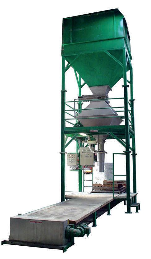
* Portable.
* Stainless steel.
* Computer controlled.
* High Capacity120 m³ per hour.
EMT
Molenpad 10, 1756 EE ‘t Zand
The Nederlands.
Tel.+31 (0) 224 591213
email: emt@emt.tech
www.emt.tech
High Speed Bagging Line

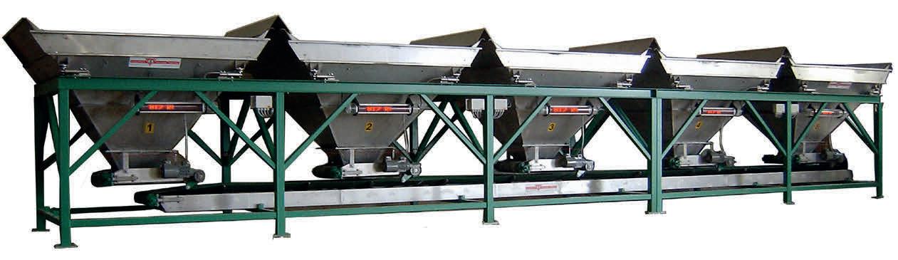
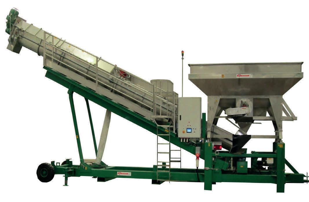
* For big bags - jumbo bags.
* Capacity 50 to 70 ton m³ per hour.
* 120 kg to 1250 kg bags.
* Suitable for granular and powder materials.
* Available with dust reducing system.
Shamrock Blender
* Capacity of 25 to 70 ton/m³ per hour.
* Machine size 4,5-5,4-7-9-11,5-14 ton.
* Easy and gentle blending process.
* Blending and weighing are separated.
Blending,
you need. Doyle Equipment Manufacturing 1 Jack Doyle Industrial Drive, Palmyra, MO. 63461 USA. Tel. +1(217) 222-1592 & +1(573) 300-4009
www.doylemfg.com
Can provide you with all the
Bagging and Transport equipment
doyle@doylemfg.com,
CHOOSING THE RIGHT ADDITIVE
54
Fertilizer manufacturers strive to produce the best possible quality fertilizers in the most efficient and responsible way. In order to achieve this, additives have to be used to help processes go more smoothly and to ensure that the fertilizers can be stored, shipped and used without problems. Examples of such additives are:
n Corrosion inhibitors.
n Binders and granulation additives.
n Defoamers.
n Coatings.
n Colouring agents.
n Solubilising agents.
n Others such as talcum powders or clays.
Besides continuously wanting to improve production and product quality, many factors encourage fertilizer manufacturers to look for alternative additives. These can be changes in legislations, composition and prices of raw materials and in the availability and prices of the additives themselves. Within the EU, the biostimulant and fertilizing products regulation (EU) 2019/1009 came into force in July 2022, prohibiting the use of non-biodegradable ingredients in agrochemicals. This has pushed many fertilizer manufacturers to look for bio-based alternatives.
Coatings
For solid fertilizers, coatings are used for the following reasons:
n To reduce caking and lumping of the fertilizers.
n To reduce moisture uptake of the fertilizers.
n To depress the liberation of dust during the handling of the fertilizers.
n To obtain a slow-release action of the fertilizer salts in the soil.
n To colour or mark the fertilizers.
Anticaking coatings
Nearly every fertilizer which is stored and handled in bulk is prone to caking. To inhibit this, anticaking coatings and sometimes inert powders such as talcum powder are applied by manufacturers. The coatings can be water-based, but the vast majority of coatings are still based on mineral oils and paraffins. When properly selected and blended in a
Jacco Korver, INSTRAL B.V, the Netherlands, discusses the advantages and disadvantages of numerous additives used by fertilizer manufacturers.
55
formulation, the latter can offer excellent anticaking performance. Prices and availability of these raw materials are coupled with the oil price, which means they can fluctuate unpredictably.
Although refined and purified mineral oils and paraffins are harmless and inherently biodegradable, their use is viewed poorly by the public. In the past, unscrupulous additive suppliers marketed anticaking coatings based on heavy fuel oils that contained high concentrations of mutagenic polycyclic aromates (PCAs), therefore giving all products based on oils and paraffins a suspicious reputation.
Other components of paraffin-based anticaking coatings are fatty (usually tallow) amines and polymers. The use of these components improves the anticaking performance from 80% to 100%.
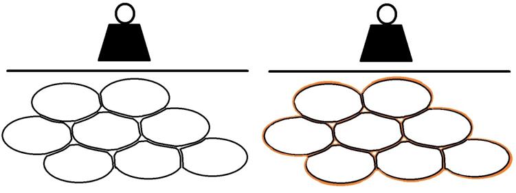
Their use does however have downsides. A side effect is that the fatty amines often give rise to dust problems when handling fertilizer.
Furthermore, tallow amines have toxicological properties, endangering factory workers and the aquatic environment. According to the harmonised classification and labelling (ATP05) approved by the EU, this substance may be fatal if it has been swallowed or has entered the airways, causing severe skin burns and eye damage, and potential damage to organs through prolonged or repeated exposure.
The particles of some fertilizer types (especially NPKs and ASNs) have the tendency to deform, even with a very low moisture content. Deformation of the granules under pressure will increase their contact surface area (and possibly rupture an applied coating) with their neighbours, causing severe caking (Figure 1). The caking tendency of fertilizer will become that much higher that even the performance of a good anticaking coating will not provide enough relief to bring the resulting caking tendency to a level that the fertilizer can straightforwardly be stored in bulk. In this case, a fertilizer producer will have to use vast amounts of anticaking coating.
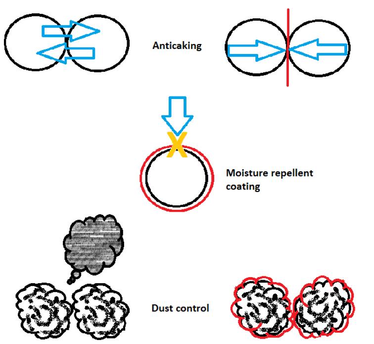
Slow release coatings
Controlled release fertilizers (CRF) are coated with a tiny layer of polymer which allows for nutrients to be released in a very timely and targeted way to various crops (trees, flowers, some cash crops). This type of fertilizer is used in closed environments such as potting plants or greenhouses. This means that nutrients (such as nitrogen, phosphorus and potassium) are released to the plants in a more targeted way, and that there are less losses to air or water. Early in 2018, the European Commission adopted a 'Strategy for Plastics in a Circular Economy', with reduction in microplastics as part of this scheme. Within its framework, the European Commission has put forward a proposal to restrict (according to Annex XIIII of REACH) some microplastics that are intentionally added to products, including polymers used in fertilizers. The ‘classic’ CRFs (and polymers in anticaking coatings) are regarded as microplastics and have to be replaced before 2026.
Dust control coatings
Poor granulation, low granule strength, rough granule surface, humidity cycles and wrong anticaking agents can give
56 | WORLD FERTILIZER | SEPTEMBER 2023
Figure 1. Deformation of fertilizer particles without coating and with coating.
Figure 2. Schematic representation of the function of coatings.
Feeding the planet starts with trouble-free fertilizer production
Together we can find new ways to advance the industry


Feeding our growing planet demands reliable operation in the production of fertilizers. Yet unexpected production downtime due to acid condensation, fouling, tube plugging and buildup in the heat exchangers, evaporators and strippers can be a roadblock to safe, efficient, and sustainable production. This is where Alleima can help. We are a leading manufacturer of high value-added products in advanced stainless steels and special alloys, titanium, zirconium and other materials.
Our roots go back to 1862 in Sandviken, Sweden and we’ve served this industry for over 60 years. We offer a wide range of trouble-free solutions – like our Sanicro® 28 for phosphoric acid evaporator, Alleima® 2RE10 or Zirconium/2RE10 bimetallic solution for nitric acid production. Sound interesting?
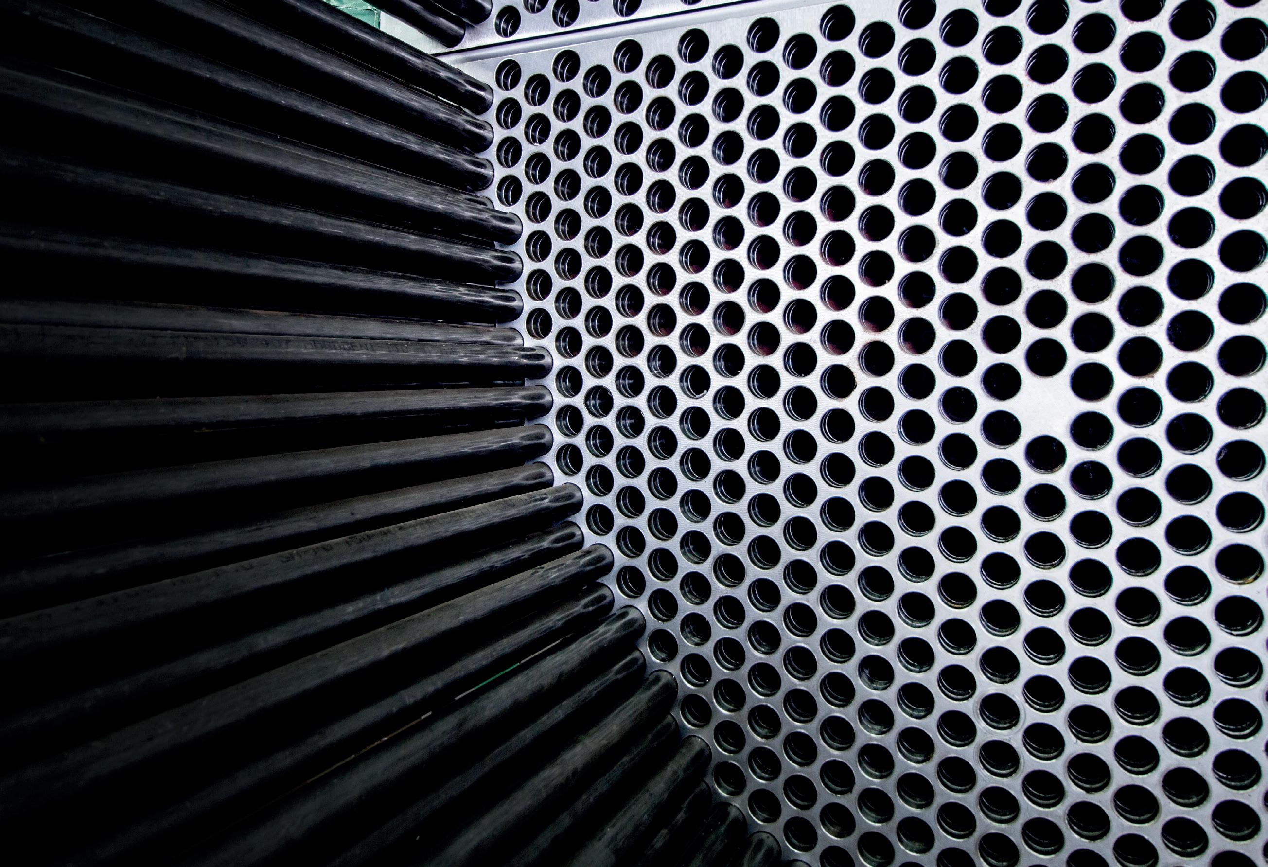
alleima.com Learn More Contact us
rise to excessive dust liberation when fertilizers are handled after storage. A proper anticaking coating should also bind dust and/or additionally talcum powder. Dust control coatings often are water-based, paraffin-based or based on natural oils.
Moisture repellent coatings
Most fertilizers are hygroscopic and several (e.g. ammonium nitrate and calcium nitrate) to such an extent that they can only be stored and shipped after applying a moisture repellent coating. These are usually paraffin based, as other types of coatings do not yet match the price/performance level that the paraffin-based coatings can.
Bio-based coatings
A lot of effort has been spent to develop suitable coatings that are bio-based, biodegradable and non-toxic. The most obvious choice would appear to be using natural oils and fats, as they appear similar to mineral oils in physical properties at first glance.
Natural oils have a lot of other useful purposes and their availability depends on harvest, which makes them expensive. Most of them possess a strong odour when applied as a coating. Chemically, natural oils are not as stable as paraffins, as they oxidise easily and become rancid. The oxidation products are gel-like sticky components that cannot be dissolved in water or other obvious solvents. What happens is similar to what happens to an ageing deep fryer at home: sticky surfaces and equipment that are nearly impossible to clean, and blockages of pipes and nozzles. Their low resistance to oxidation makes the use of natural oils also unsuitable for treating ammonium nitrate (containing) fertilizers, as ammonium nitrate is a strong oxidiser.
Other bio-based coatings are water-based and have their own restrictions. Adding extra water to carefully dried fertilizer, for one, is a bridge that many producers find difficult to cross.
Several bio-based coatings have been successfully implemented by producers for some fertilizer types. In general, bio-based coatings are still far behind the ‘classic’ coatings when it comes to price/performance level. There is also no one-size-fits-all coating on the market that can be used for a wide variety of fertilizer types.
Coatings as a cover up
The actual functions of a coating are to form a protective layer around the particles and therefore reduce the interaction between them, prevent them from taking up moisture or to dissolve in water, to reduce abrasion, or to bind dust (Figure 2). All of these are actions to patch up something that could possibly have been prevented in the first place. Coatings can also present problems during later uses of the fertilizers, such as coatings on potash in granulation of NPKs, bulk blending, or when the fertilizer is used for chemical processes or cattle feed. Implementing the use of granulation additives could help reduce the amount of coatings needed, and even make some redundant.
Granulation additives/binders
Binders are predominantly used to help agglomerate salts such as potash. They are generally dosed in 0.5 – 5 m/m% dosage. Surfactants/wetting agents, clays, several salts and urea-formaldehyde resins are other granulation additives that are used to improve the production of several fertilizer types.
Advantages of granulation additives
Companies such as Instral have developed 'classic' chemical additives, but have recently shifted to bio-based additives, reducing the ecological impact even further. Such companies strongly believe that using granulation additives is the key to further improving the quality of fertilizers and to meeting new, stricter upcoming regulations. With a couple of base formulas to start from, granulation additives can be tailored to meet unique requirements, and are specifically formulated to optimise the production process and improve the overall quality of the final fertilizer products.
Granulation additives improve the granules from the inside out, resulting in narrow particle size distribution (higher yield), round, smooth, uniform, large and hard particles and stabilised granules (no post-reactions). Granulation additives that inhibit the tendency of the fertilizer to deform will produce a fertilizer that is easier to handle and that will require no – or a far lower dosage of – anticaking coating.
Last but not least, granulation additives should offer fertilizer manufacturers more flexibility in switching between raw materials from different sources, which is often a necessity, but can give rise to problems in granulation.
When improved from the inside out, most fertilizers will require fewer coatings or no coatings at all. The treatment with bio-based coatings will also become more viable when the base quality of the fertilizer improves.
A new-generation prilling additive has already been developed, designed specifically for urea and urea-containing fertilizers. The additive can replace urea formaldehyde at similar treatment costs and – in contrast to urea formaldehyde – still works when the prills have a relative high moisture content. The prilling additive is non-hazardous and non-carcinogenic, and the urea produced can still be utilised for cattle feed, technical and DEF/AdBlue grade urea products.
Together with ICL Fertilizers Amsterdam, a binder for the difficult to granulate polysulphate was developed and successfully tested in the Amsterdam manufacturing plant in the Netherlands, producing granules that meet the market quality standard.
Conclusion
Fertilizer granules can be improved significantly from the 'inside out' additives, tackling problems like caking, lumping, moist absorption and formation of dust. With the development of bio-based additives, this opens up a world of possibilities to meet both quality and environmental standards, using coatings only as a last resort.
58 | WORLD FERTILIZER | SEPTEMBER 2023
Ron Porter and Brad Schick, Veolia Water Technologies and Solutions, and Tyler McDowell, Nutrien, Canada, explain how water clarification optimisation can boost plant reliability and reduce water footprints.
Ammonia producers require large volumes of water for their production processes, as well as for heating and cooling utility systems. Many ammonia plants meet their high raw water needs by drawing from local rivers or lakes. Due to seasonal changes, the water quality of these surface water systems can experience significant fluctuations. For this reason, ammonia facilities are required to use pretreatment systems to remove contaminants and meet the operational requirements of high-pressure steam generators.
This article examines a case study outlining how plants can evaluate, diagnose, and troubleshoot the source of operational challenges, in order to have greater water clarification optimisation, boost plant reliability and reduce water footprint.
Case study
Headquartered in Canada, Nutrien is the world’s third largest ammonia producer with an annual production capacity of approximately 7.1 million t. Among its nine nitrogen production facilities throughout Canada, the US and Trinidad is the Nutrien Redwater Nitrogen Plant. Located in Alberta, Canada, the plant has a capacity of close to 1.4 million tpy of nitrogen-based fertilizer, including other nitrogen products like nitric acid.

59
Redwater’s raw water needs are supplied by the North Saskatchewan river which originates from the Canadian Rockies and flows generally east to central Saskatchewan. For much of the year, the quality of the river water is consistently clean, but during the annual spring runoff, the composition of the water changes dramatically, as snowmelt introduces large amounts of sediment, increasing turbidity loading from contaminants such as silts, clays, and organic material.
When the river’s water quality declines, raw water intake to the plant is pretreated with cold lime softening before it is sent downstream to gravity filters and then onward to a demineralisation plant, which in turn produces high purity water for use in the steam boilers. The cold lime softener is essential for reducing raw water hardness associated with alkalinity (temporary hardness) to allow the demineralisation trains to run for longer with fewer regenerations. Since the cold lime softener is not as effective at removing physical contaminants, organics, and suspended solids due to the unique design at this facility, raw water during spring runoff is first diverted to the clarifier as the initial pretreatment step ahead of the cold lime softener and the remaining treatment stages.
Separately, another conveyance line from the clarifier transports pretreated water for use as make-up water to the plant’s cooling towers.
The basis for troubleshooting
When Veolia partnered with Nutrien Redwater in 2017 to become its water treatment solution provider, the plant had been experiencing operational difficulties coinciding with spring runoff. When these seasonal events took place, the plant historically managed the high influx of contaminant concentrations by feeding large quantities of commodity aluminium-sulfate-based chemistry to the primary clarifier. Because the raw water supply was so dynamic during these periods, it had always been assumed that the plant’s operational issues were caused by the extreme water quality fluctuations in the river.
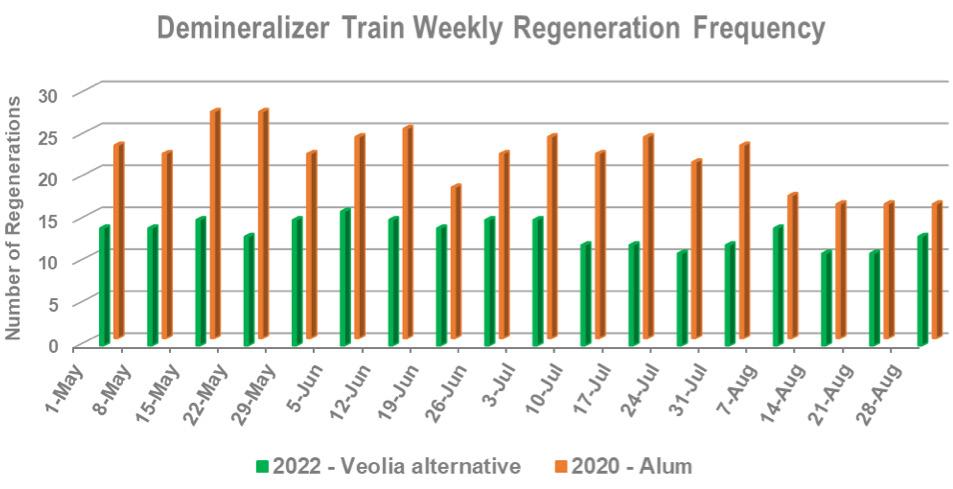
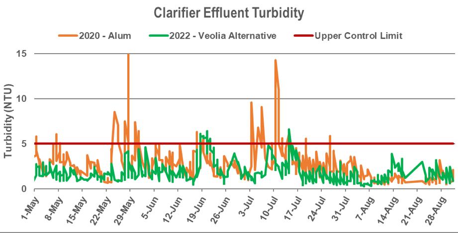
However, once Veolia’s local team familiarised themselves with the site’s operation, they could recognise that the plant’s issues – which included ion exchange demineraliser short-runs, cooling exchanger deposition and challenges in maintaining discharge quality within set limits — all pointed to the aluminium clarification chemistry.
With a clear case to troubleshoot, Veolia partnered with the plant’s operations team on a comprehensive evaluation, working collaboratively on extensive testing and analytical work over a three-year period to drill down and fully capture the consequences of the aluminium sulfate (alum) chemistry on the plant’s downstream water users. Key insights uncovered by data analytics demonstrated that the increased use of alum during spring runoff was having a negative effect on the cold lime softener outlet water quality. The aluminium sulfate was neutralising and replaced a portion of the alkalinity in the incoming water with sulfate, converting temporary hardness into permanent hardness. This limited the reduction in hardness through the cold lime softener and increased the turbidity at the clarifier outlet.
Further compounding this issue was the additional ionic loading that was being contributed from the aluminium sulfate to the treated water chemistry.
Further downstream, the increased hardness of the water, combined with the addition of sulfate species, were impacting the performance of the plant’s three ion exchange demineralisation trains. With higher levels of both dissolved and suspended solids causing an increased demand, the plant was forced to take the demineralisation units offline more frequently to be regenerated.
The demineralisation process includes cation vessels and anion vessels. Regeneration involves backwashing ion exchange resin with water to remove
60 | WORLD FERTILIZER | SEPTEMBER 2023
Figure 1. Comparison of the primary clarifier effluent turbidity during the spring and summer months of 2020 with Alum treatment and 2022 with Veolia’s alternative treatment as the primary coagulant.
Figure 2. Comparison of the frequency of demineraliser train regenerations on a weekly basis during the spring and summer of 2020 with Alum treatment and 2022 with Veolia’s alternative treatment as the primary coagulant.

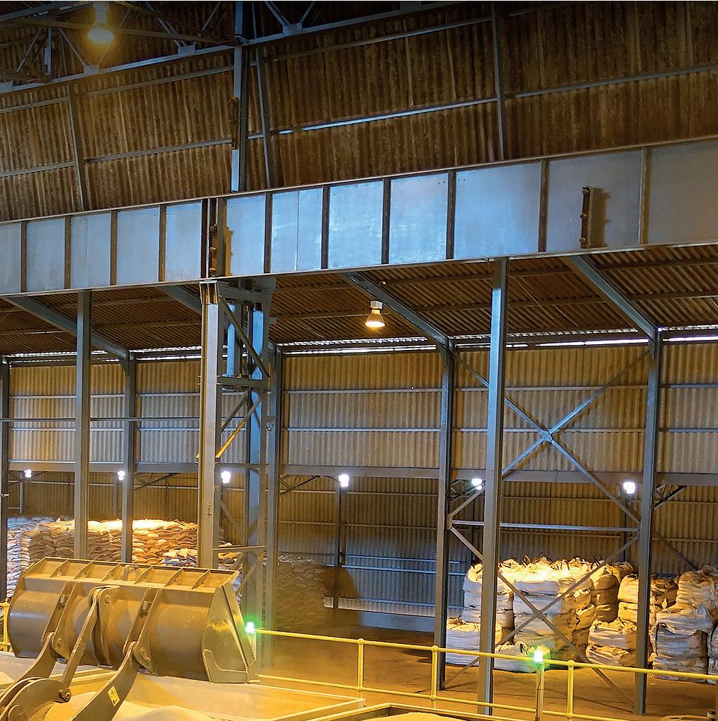
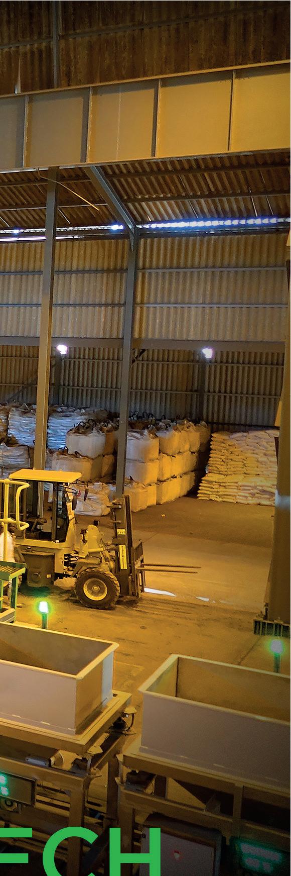


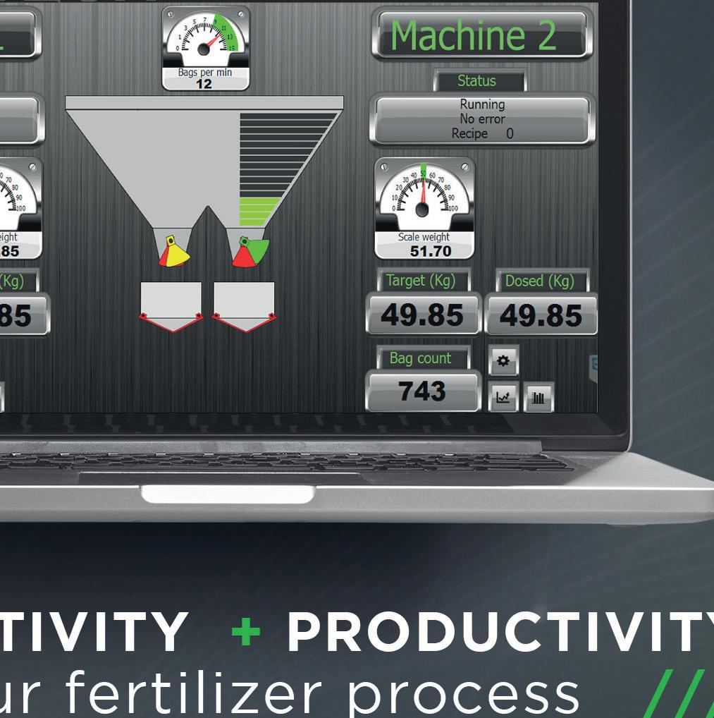


suspended matter, then applying dilute concentrations of sulfuric acid (cation unit) or sodium hydroxide (anion unit) to restore the resin to its regenerated form. Finally, the vessels are rinsed with treated water to remove traces of acid or caustic. When inlet suspended solids and organics are high, backwashes and rinses may need to be extended to restore desired demineralised outlet quality.
During a regeneration, only two of three demineralisation trains operate, which reduces the volume of water that can be supplied to sustain plant operations. More frequent or extended demineraliser regenerations might thus limit plant production rates.
Optimising the clarification chemistry
Once all parties had a clear understanding of the root causes of the operational difficulties and the implications to the plant, they explored how changing the existing chemistry could eliminate the prevailing negative downstream effects and prevent demineralisation of water supply from acting as a production bottleneck.
After a large scale trial to test and validate an alternative coagulant chemistry from Veolia’s product suite, the Redwater plant subsequently moved into full time operation. The resulting process and operational benefits included:
n Significantly less amounts of chemistry treatment needed in the primary clarifier.
n Immediately downstream, the expected performance of the cold lime softener was greatly improved.

n Loading on the demineralisation trains was reduced, decreasing the frequency and duration of regenerations.
Worldwide Coverage
n With the demineralisation trains able to operate for much longer periods, the total time of maximum water availability was increased, optimising ammonia plant production.
n Chemical (sulfuric acid and sodium hydroxide) and water usage for regenerations was substantially lowered, reducing the volume of wastewater generated.
n The plant now operates with tighter control of the desired KPI limits.
Comparing the plant’s new operational parameters under the optimised chemistry solution against the previous five years, the benefits included:
n Approximately 30 million gal./y of average water savings from reducing the frequency of regenerations.
n Average annual cost savings of over US$1 million from improved plant productivity and chemical cost savings.


Conclusion
The optimised chemistry solution and the multifaceted plant benefits present in the case study are the result of a holistic, problem-solving approach, to evaluate, diagnose, and troubleshoot the source of the plant’s operational challenges. This example shows how a customer can be supported to operate more efficiently and sustainably, leading to water and chemical savings, increased production, and cost reductions. It also demonstrates the connectivity of water across ammonia plants and how an improvement at the front end of a water treatment chain can have a cascading effect downstream, positively impacting nearly all water users across a site.
Subscribe online at www.hydrocarbonengineering.com/subscribe For in-depth coverage of the
global hydrocarbon processing sector
MORE THAN A NUTRIENT!
Aviv Bar Tal, OCI Global, the Netherlands, examines the role that nitrogen fertilizers are playing in the global food crisis.
The world faces an immense challenge: the need to produce approximately 70% more food by 2050 to sustain a projected population of 9 billion. This is only exacerbated by
agriculture’s extreme vulnerability to climate change. Rising temperatures, shifting agroecosystems, invasive pests and crops, and more frequent extreme weather events threaten the planet's entire food system.
63
These climate impacts result in reduced crop yields, diminished nutritional quality of major grains, and decreased livestock productivity.
In the pursuit to meet rising food demands while safeguarding our fragile ecosystems, nitrogen fertilizers emerge as allies in achieving the delicate balance between maximising yields and minimising soil degradation. Food cannot be produced without nitrogen fertilizer, which today accounts for 50% of food production and is essential to maximising yields and minimising soil degradation. Nitrogen fertilizers are the key nutrient for crop growth and development, as high quality nutrient-rich soil maximises farm yields and ensures healthy crops. Mineral fertilizers in general can provide substantially higher nitrogen use efficiency (NUE) than organic fertilizers – up to tenfold more depending on the type of organic fertilizer – meaning that a shift to organic fertilizers and keeping up with global food production demand is not currently feasible.
The reliance on conventional organic fertilizers presents significant challenges that extend beyond food security. These fertilizers can fall short in delivering sufficient yields, and also contribute to approximately 30% of global GHG emissions, primarily through nitrous oxide (N 2 O) emissions. This impact on climate change exacerbates the already delicate state of global food security, especially for the most vulnerable populations.
The use of synthetic fertilizers provides a much more effective source of essential nutrients for crops, but incorrect application can result in negative environmental impacts including water contamination, soil degradation, and loss of biodiversity. The effects will be seen globally without an appropriate transition to more sustainable practices.
The need for a transition to a more resource-efficient, environmentally-friendly, and low-carbon agricultural system is evident. Fundamentally, the world needs to produce more food and in a better way, while utilising fewer resources. However, this can only be achieved through meaningful partnerships between the agricultural and food industries, the employment of sustainable farming techniques, and the adoption of digital and technological innovations. The nitrogen fertilizer industry supports this transition through multiple tools that address fertilizer climate impacts along its life cycle, while ensuring food security and preventing the allocation of more land for farming.
Case study: Reducing carbon footprints of nitrogen fertilizers via low-carbon/renewable feedstocks
Ammonia is the basis of nitrogen fertilizers, and its production accounts for approximately 2% of total final energy consumption, virtually all of which comes from fossil fuels today. In 2021, the IEA published the Ammonia Technology Roadmap, which outlines technological pathways to significantly reduce GHG emissions from ammonia production, including electrolysis, pyrolysis, using biomass, and carbon capture and storage (CCS).
By decarbonising the ammonia production process, downstream nitrogen fertilizers become lower-carbon-produced products. OCI Global is an ISCC Plus certified low-carbon and renewable ammonia producer, and produces low-carbon calcium ammonium nitrate (known as Nutramon) and urea ammonia nitrate.
In addition to having globally certified low carbon footprints, these products can also be utilised in the production of everyday household goods, such as bread. Applying lower-carbon nutramon to produce lower-carbon wheat and flour results in a significant reduction of about 14% of the carbon footprint of a baguette at an insignificant incremental cost of €0.0028 to the consumer. 1
There is promising momentum and scalability in a more large-scale ammonia transition to low-carbon and renewable feedstocks. Examples include the company's 1.1 million tpy blue ammonia greenfield project in Texas, USA, and its green ammonia project in Egypt, which has successfully produced and sold commercial green ammonia.
However, these pathways require significant capital investment and still result in higher cost of production compared to the status quo. Without collaboration throughout the ammonia and nitrogen fertilizer value chain, and without crucial regulatory and financial incentives, the transition to low-carbon and renewable ammonia and nitrogen fertilizers will remain out of reach for many producers.
Developing nutrient efficient products to reduce losses and increase yield
There is clear evidence that inhibitors (nitrification inhibitors and urase inhibitors) are indispensable means on the road to net zero Scope 3 emissions to decarbonise the nitrogen fertilizer industry.
These inhibitors have been recognised in recent years by scholars as having numerous positive effects, including:
n Enhanced nitrogen management: urease inhibitors regulate the conversion of urea into ammonia, reducing nitrogen losses through volatilisation.
Nitrification inhibitors slow down the conversion of ammonium to nitrate by inhibiting nitrifying bacteria. This delay reduces nitrogen leaching, as nitrate is more susceptible to leaching. By preserving ammonium forms, nitrification inhibitors increase the availability of nitrogen for plant uptake, improving crop productivity.
n Minimised GHG emissions: the excessive release of GHG, particularly N 2 O, from agricultural activities contributes to climate change. Urease inhibitors and nitrification inhibitors effectively mitigate these emissions. Urease inhibitors reduce ammonia volatilisation, a significant source of N 2 O emissions. Nitrification inhibitors inhibit the production of nitrate, a precursor of N 2 O, and minimise the availability of nitrogen compounds for denitrification, thereby reducing N 2 O emissions. Consequently, the use of these inhibitors helps
64 | WORLD FERTILIZER | SEPTEMBER 2023
farmers in their efforts to mitigate climate change and meet sustainability targets.
n Improved water quality: urease inhibitors play a critical role in reducing nutrient losses and protecting water quality. The inhibitors reduce the volatilisation of ammonia, preventing its deposition in water bodies. By preserving ammonium forms, nitrification inhibitors reduce nitrogen losses through leaching, thereby safeguarding water quality and minimising the impact on aquatic ecosystems.
n Improved farm economics: implementing urease and nitrification inhibitors within farming is straightforward and does not require investments in specialised equipment. The slowed conversion of the nitrogen form in soils enables more temporal flexibility in nitrogen fertilizer application, easing the farm management in tight spring season. Increased nitrogen use efficacy and smoother nitrogen supply enables a reduction of fertilizer application rates, with gains in productivity. Using urease and nitrification inhibitors can help elevate the farming economy and help farmers to remain compliant with rules and regulations.
Accordingly, inhibitors applied to nitrogen fertilizers positively impact the nitrogen metabolism in soils. This directly reduces GHG emissions, reduces the risk of nitrate leaching and ammonia emissions, results in improved nutrient use efficiency (NUE) to lower environmental burden, and in turn stabilises food supply at high productivity levels. This technique also protects natural areas against change to agriculture, and protects marginal areas against intensification.
Collaborating across the value chain to promote sustainable intensification
The former can not be achieved without the right regulatory support and incentives for low carbon fertilizers and sustainable fertilizers, and without collaboration across the value chain. Firstly, farmers should be incentivised and supported with the right tools and education programmes to apply sustainable intensification practices to maximise the use of existing farmland. Measures include:
n The use of harmonised standards and indicators such as the NUE Indicator. This was developed by
the EU Nitrogen Expert Panel, and provides information about resource use efficiency.
n The use of precision farming tools and techniques that can help farmers to effectively assess crop nutrient requirements.
n An increase in the replacement of conventional mineral fertilizers with inhibited fertilizers, which improve fertilizer use efficiency, mitigate climate change, and reduce nitrogen losses to the environment significantly.
n The adoption of ‘4R’ principles: using the right fertilizer source at the right rate, at the right time and in the right place.
n The use of targeted fertigation techniques.
n The use of low-carbon and renewable ammonia in fertilizer production, helping to reduce overall Scope 1 GHG emissions.
Secondly, public policy must evolve, given its crucial influence on farmers’ business decisions. Some established policies, having achieved their initial objectives, now create perverse incentives for inefficient fertilizer use and should be reformed. In other areas, new regulations, payments or emissions pricing schemes are needed to incentivise more sustainable practices. The appropriate controls will vary by geography and farm type, and those making reforms should carefully consider the impacts on farmers. Finally, the economics must make sense for both the farmers, and the producers. Accordingly, governments should also provide incentives and funding opportunities to ammonia and nitrogen fertilizer producers who carry the burden of having to invest in technologies and alternative feedstocks without commensurate economics to support the transition.
Conclusion

Together, food security and net zero can be acheived, but currently, there are too many obstacles preventing this necessary goal from becoming a reality. In order for this to be realised, collaboration is needed across the value chain from governments, producers and farmers.
Notes
1. Calculation by OCI Global of cradle-to-retail incremental cost to the consumer of using lower-carbon Nutramon compared to grey Nutramon, all else equal.
BELIEVING SEEING IS
Take a look at our ABC Certificate. It shows our circulation has been independently verified to industry agreed standards. So our advertisers know they’re getting what they paid for.
ABC. See it. Believe it. Trust it.

www.abc.org.uk 2018_seeing is beliving house ad_full A4.indd 4 10/12/2019 16:40:23
Kazuki Kamikubo, TOYO Engineering, Japan, discusses the significance of new urea technologies and outlines the benefits of lowered synthesis pressure for producers.
he fertilizer industry is set to reap the rewards of new and improved urea technologies, which will impact upon the sustainable growth of the global community.
Ater establishing the ACES21 ® urea technology in the late 1990s, TOYO Engineering has recently been working on further improvements and innovations for an updated urea process. The new process realises further energy savings and plant cost savings, while maintaining the salient features of the previous technology. This is achieved by lowering its synthesis pressure, based on the knowledge accumulated from pilot plant testing, and the design study for material selection and corrosion prevention of ACES21 commercial plants.
The updated technology, ACES21-LP®, 1,2 lowers synthesis pressure to 136 barG from 152 barG, through the application of DP28W TM duplex stainless steel and 316L stainless steel in the urea
67
synthesis section. This material selection enhances corrosion resistance and enables a reduction of the passivation air required. As a result, less inert gas
(passivation air) enters the synthesis section. The new technology further reduces energy consumption, as a product of reduced power consumption of rotating machines for pressurising feedstock, improved stripping efficiency, and a reduced cost and weight of high-pressure synthesis equipment.
Technological innovations in lowering urea synthesis pressure
The development of the urea process has led to the lowering of synthesis pressure step-by-step from 245 barG to 152 barG, thanks to technological advancements over time (Figure 1). The new technology reduces the urea synthesis pressure to 136 barG, owing to optimised materials selection and process conditions in urea synthesis. The application of DP28W duplex stainless steel and 316L stainless steel in the synthesis section can reduce passivation air significantly, and as a result, the performance of the carbamate condenser can be greatly improved, as the partial pressure of inert gas (O 2 and N 2 ) for urea synthesis is substantially reduced. Thus, the same operating temperature of the vertical submerged carbamate condenser and reactor at 136 barG is maintained.
Passivation property of material for urea synthesis section
Oxygen concentration becomes the lowest at the stripper and stripper outlet gas stream. Since DP28W is normally applied to the stripper as proprietary equipment, the passivation requirement of the stripper outlet piping determines the required oxygen content in the CO 2 fed to synthesis section. Figure 2 shows the minimum required oxygen concentration for passivation in the gas phase to prevent active corrosion of the duplex stainless steel and 316L UG identified by TOYO’s intensive R&D and electrochemical studies. Figure 3 shows a correlation between the oxygen concentration in the stripper outlet gas, and oxygen concentration in CO 2 fed to the synthesis section, with the required oxygen concentration to passivate each material. This indicates that passivation air can be reduced by applying duplex stainless steel or DP28W to the stripper top outlet piping in comparison with 316L piping.
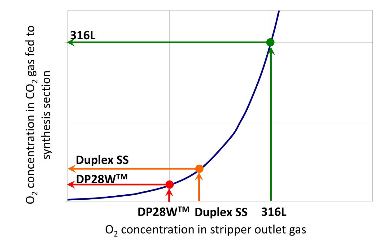
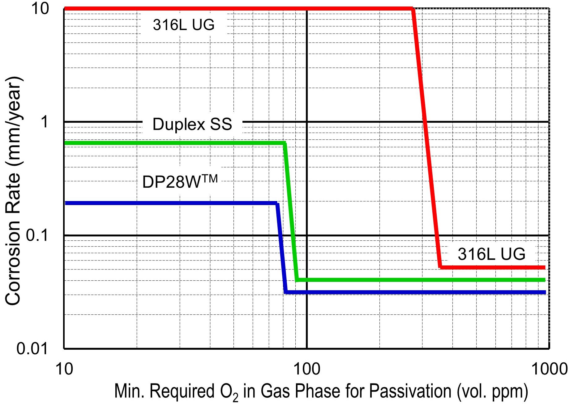
Material selection of the synthesis section
Figure 4 shows a schematic process flow diagram of ACES21-LP synthesis section with construction materials. TOYO’s approach is to tailor the selection of suitable and reliable materials for equipment and piping according
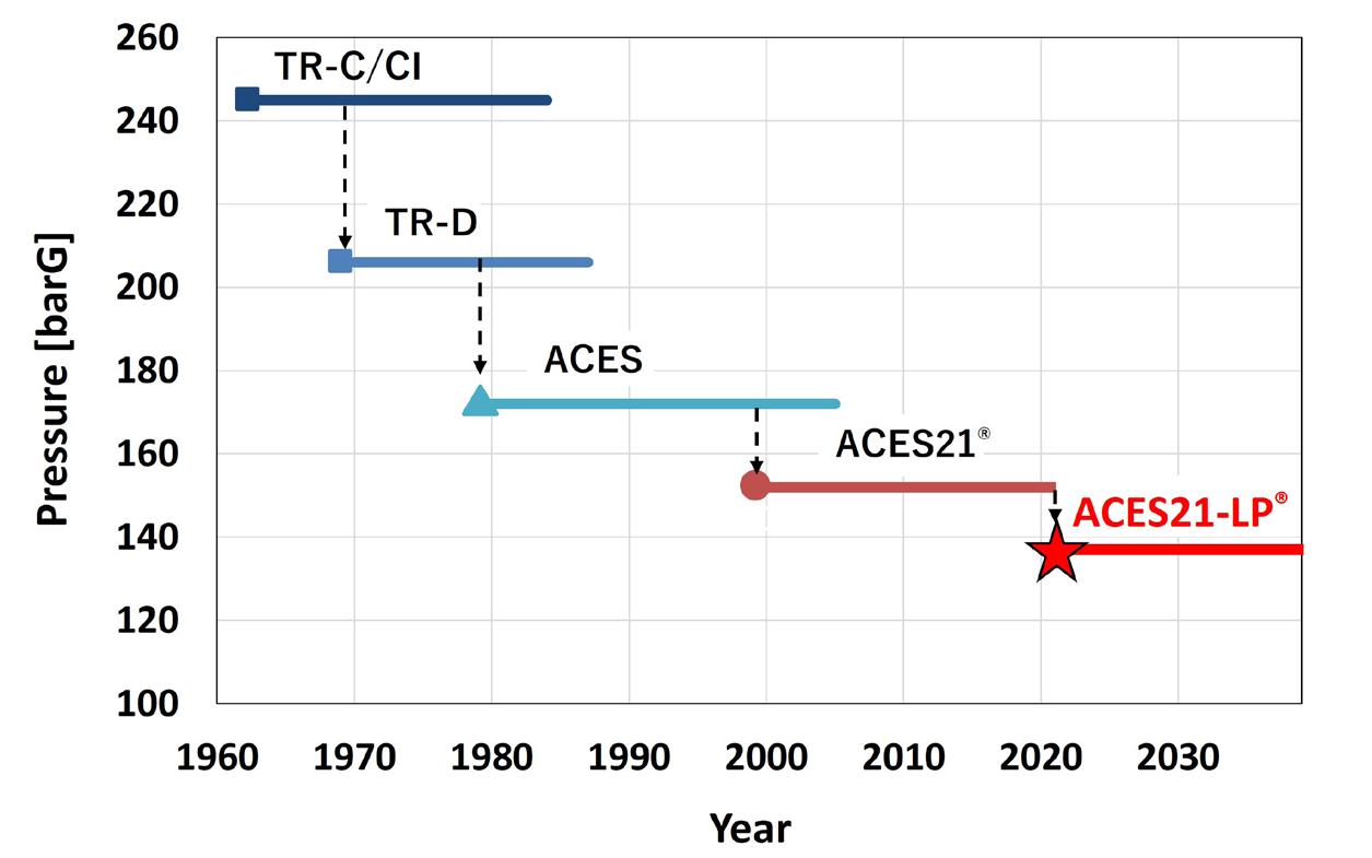
68 | WORLD FERTILIZER | SEPTEMBER 2023
Figure 1. A history of lowering urea synthesis pressure.
Figure 2. Minimum required oxygen concentration for passivation.
Figure 3. O2 concentration in stripper outlet gas and O2 concentration in CO2 gas fed to the synthesis section.

to the service conditions, specifically considering the corrosiveness of the environment, and avoid the use of costly material where necessary. The upgraded duplex stainless steel or DP28W piping is typically shorter than 10 m, thus extra expenses to upgrade the materials are minimal.
Synthesis pressure as low as 136 barG provides multiple benefits, such as enhanced reliability and safety by relaxing mechanical design conditions, a lighter weight of high-pressure equipment and machineries, a significant reduction of power requirements in the CO 2 compressor, ammonia and carbamate pumps, and improved stripping efficiency.
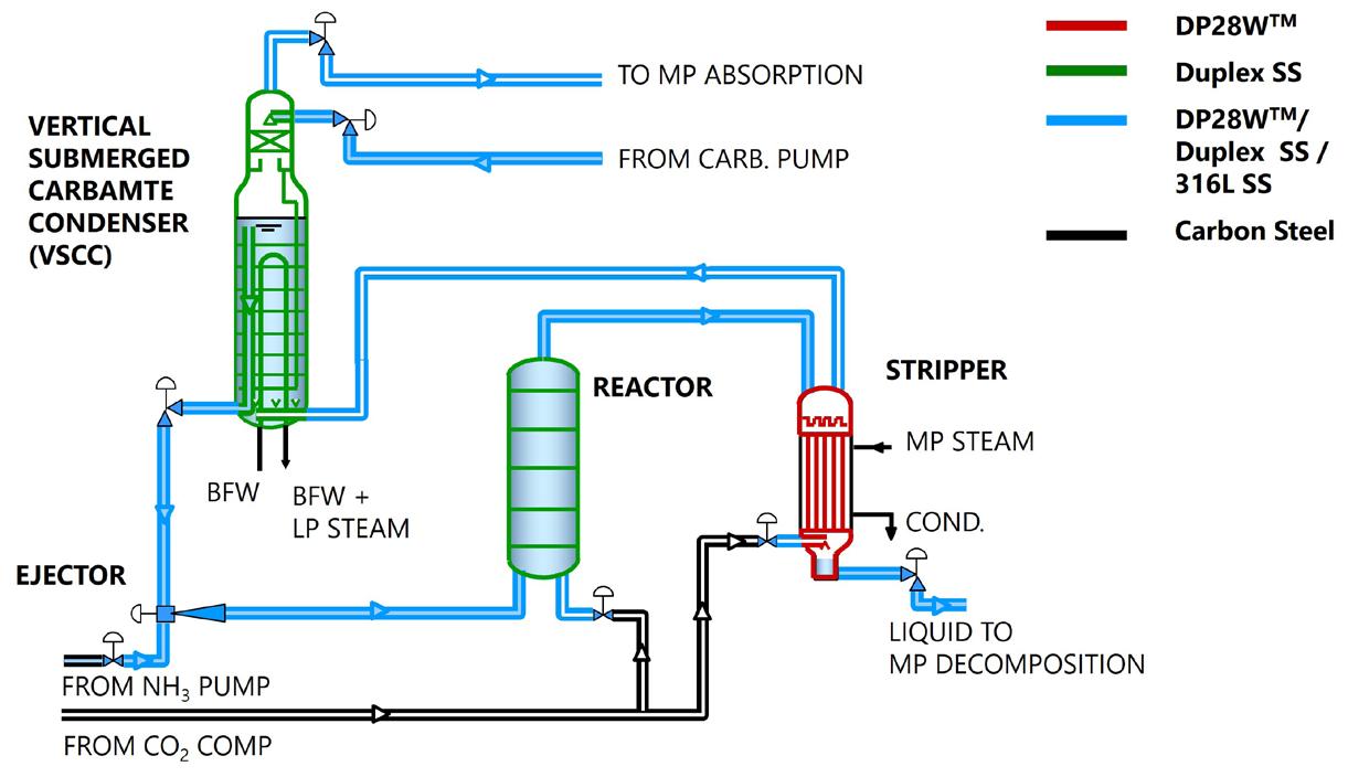
The new generation of the technology enhances features of the original version:
n 10% lower synthesis pressure than ACES21 owing to the uniquely optimised synthesis conditions and reduced passivation air requirement.
n Higher CO 2 conversion.
n Further energy savings (and less OPEX) owing to reduced power requirements of the CO 2 compressor, ammonia and carbamate pumps.
n Lighter weight of HP equipment in the synthesis section by 5 – 10%.
Figure 5 shows expected OPEX reduction by ACES21-LP in comparison with ACES21 for a new plant application. Annual OPEX can be reduced, saving approximately US$0.4 – 1.2 million depending on natural gas price. This amount is enough to compensate the additional expense of upgrading some piping in the synthesis section within a year, thus plant owners can reap the benefits of saving approximately US$8 – 23 million cumulatively across 20 years of operation.
Upgrading urea plants
Existing plants utilising TOYO’s original technology can be upgraded by replacing some existing stainless steel piping in most corrosive areas with DP28W or duplex stainless steel, fully re-utilising existing HP synthesis equipment and machineries in-situ without modifications.
Thanks to the lowered operating pressure, energy consumption is reduced by 3 – 5% and urea production can be increased by 3%, by utilising extra capacities created through the reduced compression ratio of the CO 2 compressor and reduced head of the NH 3 pump and carbamate pump. Accordingly, specific GHG emissions per ton of urea decrease in accordance with the reduction of specific energy consumption.
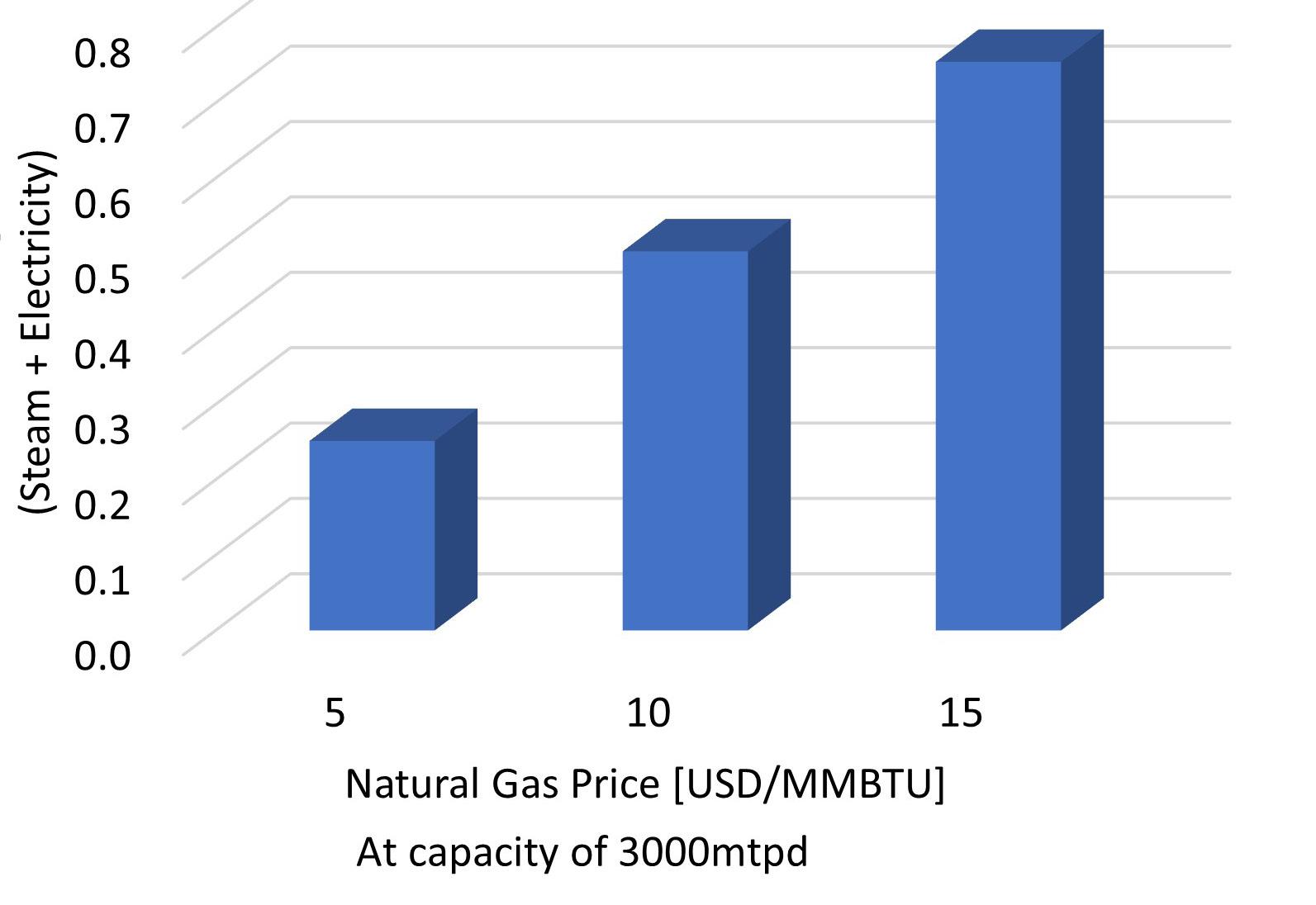
Figure 6 shows the OPEX savings by power reduction of high-pressure pumps (for NH 3 and carbamate) after converting an existing ACES21 plant to ACES21-LP without production increase. Savings in OPEX can be seen to account for US$0.2 – 0.7 million annually depending on natural gas price. Thus, the expense for upgrading a urea plant could be recovered within a few years, even in the case of cheap natural gas at US$5/MMBtu, and needless to say, higher natural gas prices would shorten this payout time.
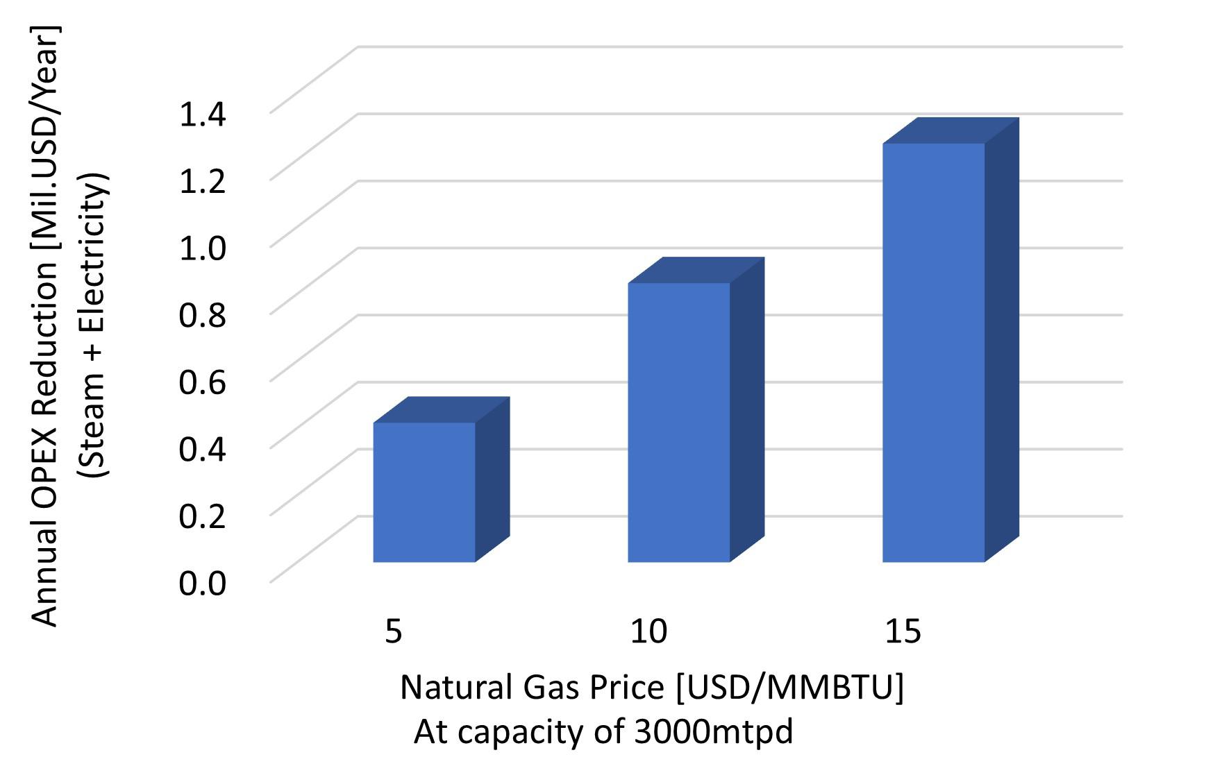
70 | WORLD FERTILIZER | SEPTEMBER 2023
Figure 4. Standard material selection in the ACES21-LP synthesis section.
Figure 5. OPEX reduction by ACES21-LP.
Figure 6. OPEX savings after conversion to ACES21-LP.

Figure 7 shows an expected rise of gross profits in the case that production is increased, utilising extra capacities created by a reduced compression ratio in the CO 2 compressor and a reduced head of the NH 3 pump and carbamate pump. The production rate could be increased by approximately 3%, whilst maintaining energy consumption, and generating an additional gross profit of approximately US$0.8 – 18 million annually depending on prices of natural gas and urea. A rather conservative case of US$10/MMBtu natural gas and US$500/t urea provides
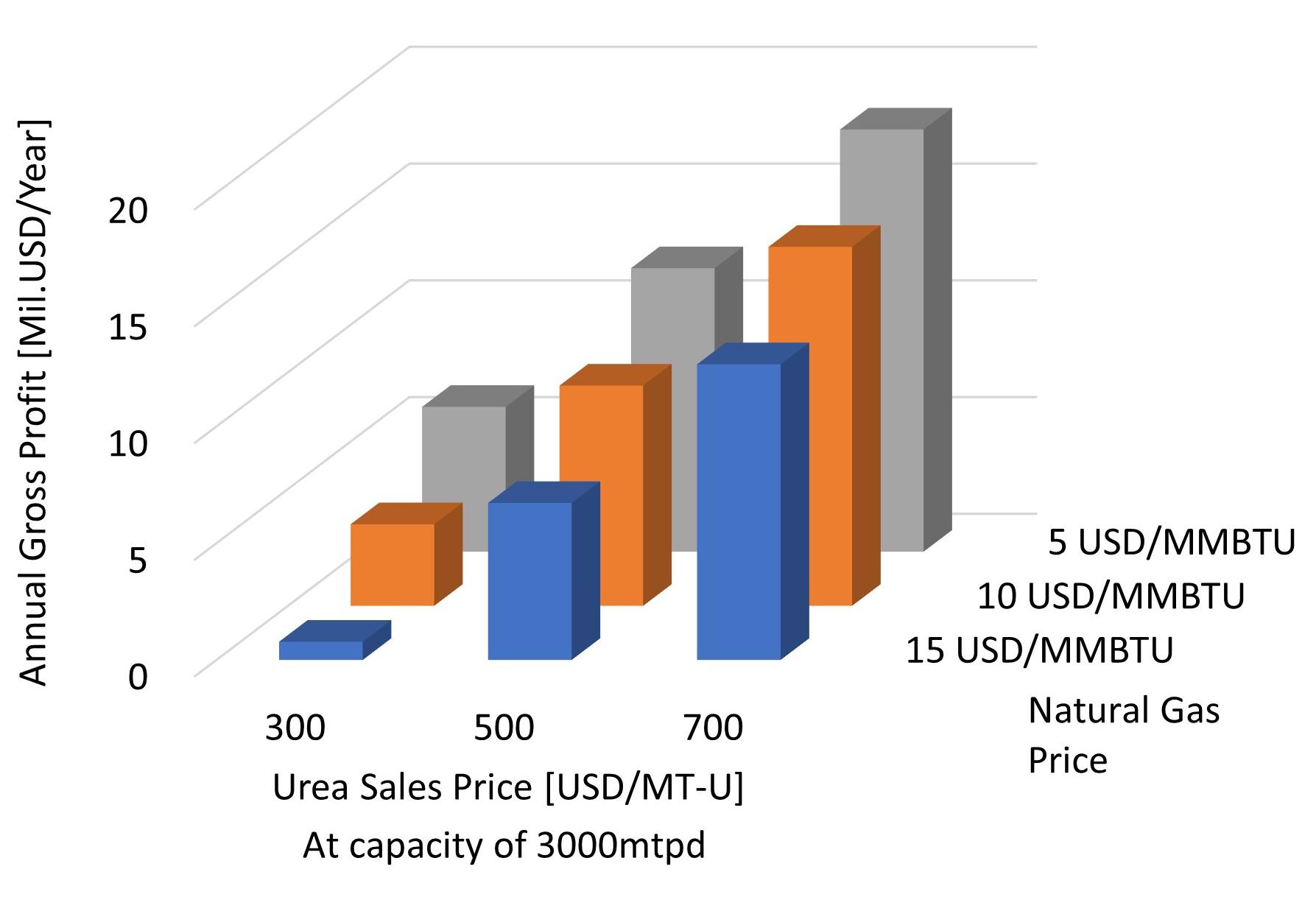
Stay informed
additional gross profit of approximately US$9 million annually. In this case, expenses for conversion to ACES21-LP could be recovered within a month.
Conclusion

The new urea process realises a synthesis pressure of 136 barG through a combination of DP28W duplex stainless steel and 316L stainless steel piping, as well as reduced passivation air in the synthesis section. The low-pressure synthesis achieved through the updated technology realises further energy savings, owing to reduced power requirements of the CO 2 compressor, ammonia and carbamate pumps, and reduced weight of HP equipment in the synthesis section, owing to the milder mechanical design conditions.
The fertilizer industry will reap the rewards of improved urea technologies, which will impact upon the sustainable growth of the global community.
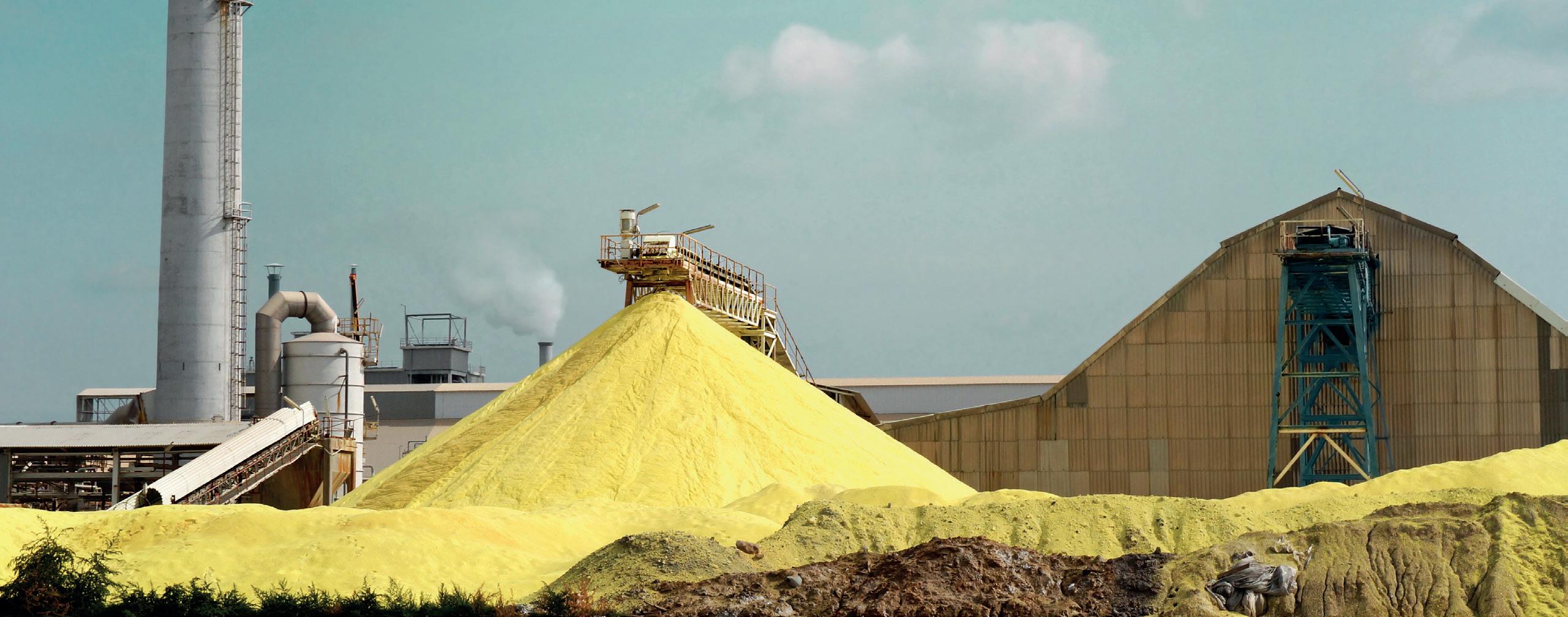
References
1. YANAGAWA, T., “Toyo’s latest innovation in urea synthesis technology and sustainable urea production”, Nitrogen + Syngas 2022
2. YANAGAWA, T., “Toyo’s New Urea Process “ACES21-LP®” Provides Great Benefits to Urea Plant Owners in Cost and Energy Savings”, Nitrogen + Syngas 2023, International Conference & Exhibition.
Figure 7. Gross profit increase after conversion to updated urea technology.
Follow us to stay up to date and hear the latest World Fertilizer News Register at www.worldfertilizer.com
Robert van Spingelen and Chris Thornton, European Sustainable Phosphorus Platform, Belgium, explain how phosphorus recycling could result in a synergy of mineral and organic carbon fertilizers.
Geopolitics and public policies are increasingly pushing towards phosphorus recycling in Europe, and the new EU Fertilizing Products Regulations are opening doors for such opportunities.
Russia’s war against Ukraine, and the resulting sanctions, have caused a price and supply crisis for phosphate fertilizers in Europe, albeit less acute than for ammonia. In response to this, the European Commission have advocated for “better access to organic fertilizers and nutrients from recycled waste-streams”. 1
Policy in Europe is led by The EU Green Deal (2019), and a circular economy action plan and biodiversity and farm-to-fork strategies are in place to reduce nutrient losses by at least 50%, without soil fertility deteriorating. These strategies are set to result in a reduction in fertilizer use of at least 20%. 2 Phosphate rock remains on the proposed updated list of EU Critical Raw Materials. 3

73
Phosphorus recycling requirements from sewage are already part of the law in Germany and Switzerland, and will be implemented over the coming years, and similar legislation has also been notified to the EU by Austria.
EU policy continues to push nutrient recycling
The revision of the EU Urban Waste Water Treatment Directive that is under discussion will enable the commission to fix phosphorus and nitrogen recycling requirements from sewage. Phosphorus recovery from sewage is included in the EU taxonomy proposals. Recovered precipitated phosphates (including struvite) have been authorised in certified organic farming in Europe since January 4 and ESPP is proposing the authorisation of other recycled nutrient products within the organic farming movement.
These developments provide opportunities for the fertilizer industry, but are not without logistical and market challenges. A very wide range of technologies and approaches for recycling phosphorus (and other nutrients) are available today, with a number that have been technically proven full-scale, despite questions outstanding on cost. Around 40 technologies are presented in the catalogue developed online by ESPP, which centres around practical information, such as limits to input material, the nature and quality of products, and the number and size of installations operational today. 5
Different and disparate recycling routes
Some of these technologies produce high quality chemicals, such as phosphoric acid extraction from sewage sludge ashes, and recovery of potassium salts from municipal solid waste.

Another approach is to integrate ashes directly into fertilizer production, an idea that is currently being developed by ICL and Borealis, rendering the phosphorus in the ash more plant available, or to improve ashes by thermochemical treatment, as currently being developed by Outotec AshDec.
Kemira/ViviMag have also been able to recover pure iron phosphate from sewage, but the agronomic value is unclear except in specific cases of iron-deficient soils.
Struvite recovery (magnesium ammonium phosphate) is today a known technology, with around 50 installations operational in Europe (e.g. from Ostara, NuReSys, Veolia, and Suez). The product is recognised as a suitable fertilizer, with nutrient release according to plant needs, and quality producers have seen higher demand than production. Struvite recovery is a recognised BAT (best available technology) under the EU industrial emissions directive for the food, drink and milk industries and is being tested in the abattoir industry. Scale is however small compared to the fertilizer market, with around 5000 tpy P 2 O 5 equivalent total struvite production in Europe today. 6
Synergy of mineral and organic-carbon fertilizers
A range of processes enable phosphorus and other nutrient recovery in organic forms. These include feeding algae with wastewater, then processing the biomass, enrichment and stabilisation of manure or digestate, pyrolysis/biochars, CCm CO 2 fixation and N stabilisation in
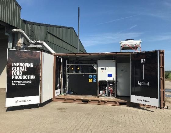
74 | WORLD FERTILIZER | SEPTEMBER 2023
Figure 1. Phosphorus recycling from municipal sewage: EnDEv Paku, Finland.
Figure 2. Nitrogen valorisation in manure: N2 Applied.
organics, fixing of nutrients into secondary organic materials, and processed digestates. These will accelerate with the expected considerable increases in production of digestate and compost in Europe, resulting from EU biogas production policy – a ten times increase in anaerobic digestion by 2030, in particular from manure – and the obligation to separately collect municipal ‘biowaste’, which is expected to double quantities. Combined with existing streams from the food and beverage industry, animal feed and biofuel processing, these flows offer major opportunities to develop organo-mineral fertilizers, offering soil organic carbon benefits for farmers. This is now eligible for the CE-mark under the EU Fertilizing Products Regulation. These opportunities were discussed at the second SOFIE (Summit of the Organic Fertilisers Industry in Europe), involving Yara, UNIMER, TEMA Ferm O Feed, Protix, and DCM.
Challenges to markets and logistics of decentralised recycling
As shown by the prior examples, recycling is a small-scale and decentralised industry. Even large sewage works or food processing sites or biogas plants have throughflows of only hundreds or one or two thousand tpy of phosphorus and nitrogen. Challenges to the mineral fertilizer industry today include how to integrate these local, small-scale streams of secondary nutrients into logistics and marketing. The recycled products can offer agronomic benefits (organic carbon and adapted nutrient release) as well as ‘green’ credentials, but logistics may be prohibitive to intake into a centralised manufacturing, distribution and marketing system, meaning that regional re-processing, distribution and sales are required.
The EU Fertilizing Products Regulation enables access to the CE-mark for organic and inorganic fertilizers with inputs including digestates, composts, animal by-products (not yet today possible with first authorisations underway), sewage sludge ashes and other ashes, pyrolysis and gasification materials, struvite and precipitated phosphates, and recovered ammonia salts from gas stripping. However, certification may prove complex and expensive for products derived from secondary materials from different, local suppliers.
Nitrogen recovery: Looking for ammonia gas solutions
For nitrogen recovery, the situation is similar. An increasing number of sites are ‘stripping’ ammonia from digestate or wastewater, as well as many sites already scrubbing NO x from offgases, and proposing ‘recovered’ nitrogen as dilute ammonia salts or ammonia water aqueous solutions. These can be used locally on fields, or possibly to feed algae or microbial protein production, but transport over any distance is prohibitive. Case studies have been presented in the conclusions of a first workshop on nitrogen recovery (white ammonia). It seems that there is a
need to develop technologies which can recover ammonia as a high-nitrogen solid (e.g. as urea) or as a compressed gas (ammonia gas can be released from adsorbents). As for phosphorus recycling, a challenge for the fertilizer industry is logistics and marketing to intake the distribute recovered nitrogen products.
Bringing together different industries
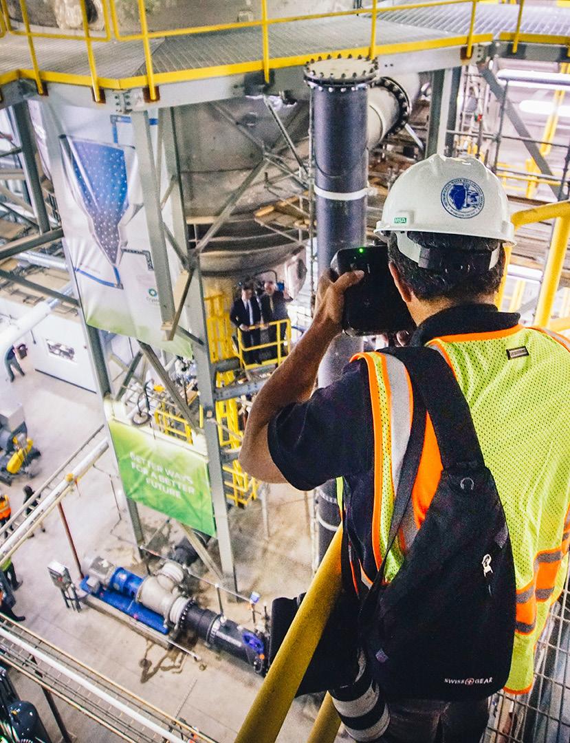
ESPP is working to help move nutrient recycling forward, by bringing together the fertilizer industry, waste and water management companies, recycling technology providers and research expertise centres and projects. Meetings, information exchange and dialogue between members in different sectors, and with policy makers, aims to improve understanding, build links and progressively enable value-chain solutions to logistics challenges.
References
1. www.ec.europa.eu/commission/presscorner/detail/en/ ip_22_6564
2. www.eur-lex.europa.eu/legal-content/EN/TXT/?qid=1590 404602495&uri=CELEX%3A52020DC0381Phosphate
3. www.ec.europa.eu/info/law/better-regulation/haveyour-say/initiatives/13597-European-Critical-RawMaterials-Act_en
4. www.eur-lex.europa.eu/legal-content/EN/ TXT/?uri=CELEX:32023R0121
5. www.phosphorusplatform.eu/techcatalogue
6. www.phosphorusplatform.eu/images/download/ Kabbe_P-recovery_tech_implementation%20Table_202301-04.pdf
SEPTEMBER 2023 | WORLD FERTILIZER | 75
Figure 3. Phosphorus recovery as struvite: Ostara Crystal Green.
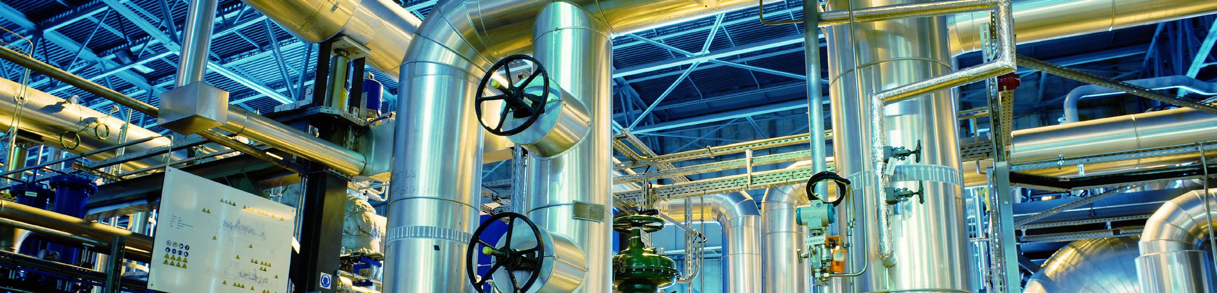

25 | Andritz AG 61 | Bagtech 13 | Black & Veatch 31 | Blasch Precision Ceramics Inc./ BD Energy Systems 15 | Boldrocchi Group 45 | BORSIG Gmbh OBC | Casale SA 19 | Christy Catalytics 46 | CRU Group 02 | Curtiss-Wright EST Group 29 | ECS Catalyst, LLC. 76 | WORLD FERTILIZER | SEPTEMBER 2023 AD INDEX 53 | EMT/Doyle Equipment Manufacturing IFC | Eurotecnica 09 | Halliburton Multi-Chem 71 | Hitard Engineering 62 | Hydrocarbon Engineering 69 | J&H Equipment Inc. OFC, 21 | Kreber B.V. 04 | Luengo Color S.L.U 35 | Mannesmann Stainless Tubes GmbH IBC | Neelam Aqua and Specialty Chem (P) Ltd. 07 | Sabin Metal Corporation 65 | Sohar Sulphur Fertilizers LLC 43 | thyssenkrupp 39 | Topsoe 49, 72, 76 | World Fertilizer The home for the latest fertilizer manufacturing news, analysis, comments, and events Visit our website today www.worldfertilizer.com World Fertilizer online

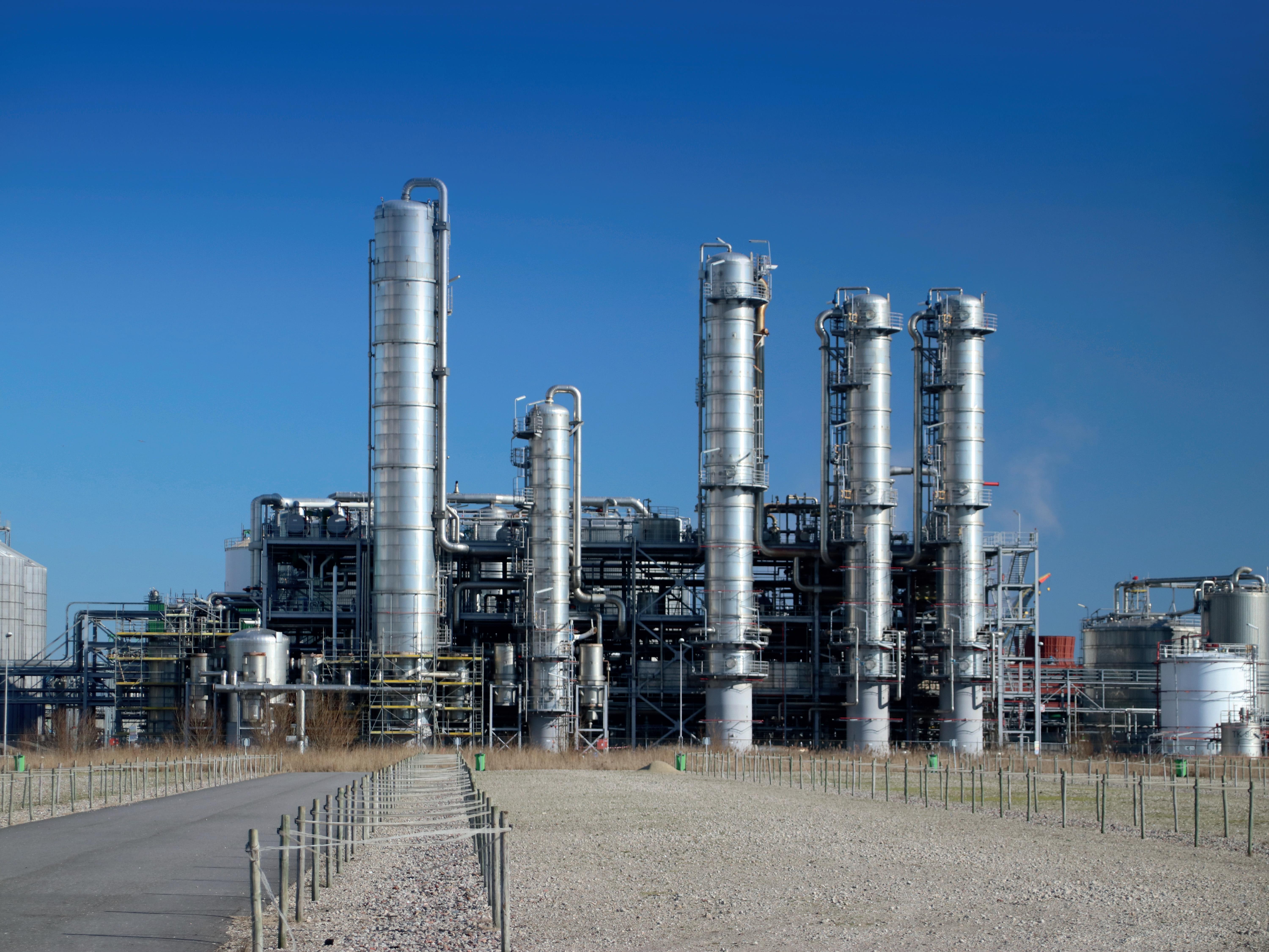
www.casale.ch | info@casale.ch
