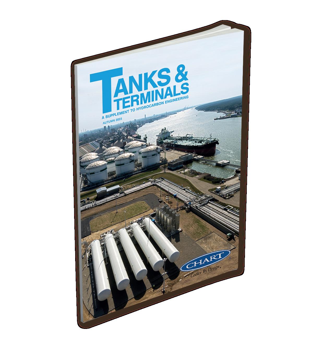
AUTUMN 2 023

BREEZE ESP+ is the leading cloud-based software (using AP-42 Ch.7 methods) that enables terminal customers to easily calculate, track, store, and report on air emissions from tanks and other sources commonly found at their facilities, such as:

f Catch pans
f Combustion units
f Control devices
f Equipment leaks
f Line/vessel openings
f Sumps/oil-water separators
f Tanks
f Trucks
In addition, we offer our customers a wide range of EHS services to help ensure compliance with applicable environmental rules and regulations, including:
f Permitting and compliance assistance
f Environmental Justice assessments and assistance
f NSPS and NESHAP/MACT support
f Transportation fuel compliance
Contact us today!
Ng

Neil Wragg, Joao Vasques and Joe Nichols, DNV, UK, discuss how digitalisation is vital to ensuring that FSRUs are operating as efficiently as possible.
Kevin
drive dramatic improvement
As artificial intelligence (AI) brings unparalleled change to the storage sector, Danny Constantinis, EM&I Group, Malta, outlines the importance of accountability at all levels within the sector.
27
Chris Platt, Re-Gen Robotics, UK, discusses how terminal operators are profiting from the use of robotic cleaning in their storage tanks.
Craig Senych, Eddyfi Technologies, Canada, outlines how the integration of robotic inspection crawlers in the tanks and terminals industry offers advantages in safety, efficiency, and cost-effectiveness.
Borja Maestro, Tecam, Spain, explains how the tank storage industry is tackling environmental issues, particularly the treatment of venting gas emissions.
Dr. Alexander Zelck, Timm Technology, Germany, provides a case study of a bottom loading overfill incident and explains what can be learnt from the experience.
Jente Quintens, Owens Corning, explains why storage tank owners should adopt the practice of insulating tank bases and the criteria that should be considered when designing insulation systems for such purposes.
Tony Collins, EonCoat, USA, discusses how the tank industry is evolving to implement more effective corrosion prevention techniques.
Geoff VanLeeuwen, Blackmer, USA, explains how the liquid terminal industry can save time by ensuring that the right pump is selected.

Tanks & Terminals talks to Edward J. Cass, Technology Manager, Paratherm Heat Transfer Fluids.
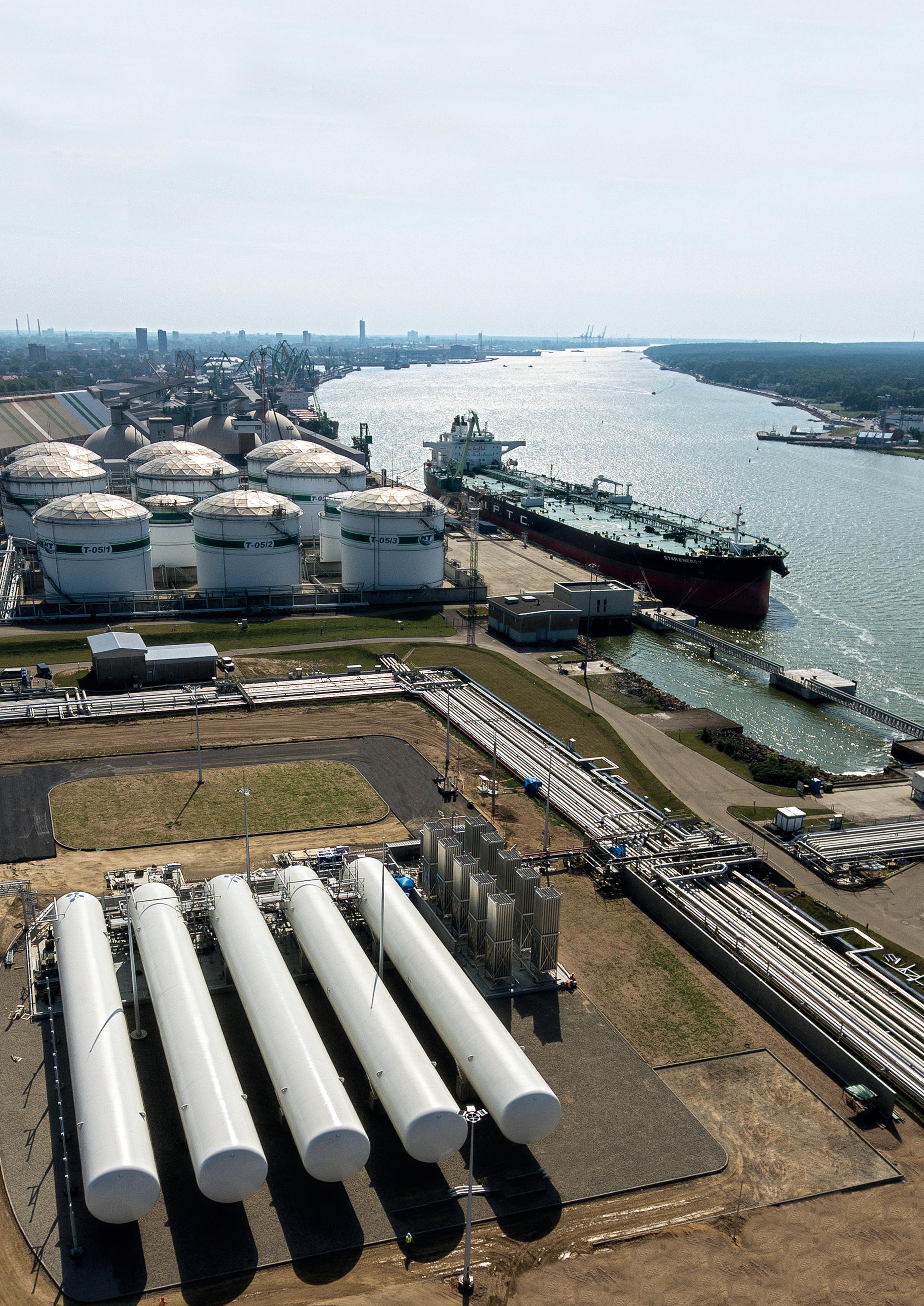
Chart provides a complete range of bulk cryogenic storage tanks and solutions delivering proven reliability, reduced maintenance, and lowest cost of ownership for the full spectrum of liquefied gases, including hydrogen and LNG. Chart Vacuum Technology guarantees highest thermal performance and extended hold times. All tanks are shop built and total storage capacities can be modularised, which significantly reduces civil engineering, installation costs and schedule.

MANAGING EDITOR James Little james.little@palladianpublications.com
SENIOR EDITOR Callum O’Reilly callum.oreilly@palladianpublications.com
EDITORIAL ASSISTANT Jack Roscoe jack.roscoe@palladianpublications.com
SALES DIRECTOR Rod Hardy rod.hardy@palladianpublications.com
SALES MANAGER Chris Atkin chris.atkin@palladianpublications.com

SALES EXECUTIVE Sophie Barrett sophie.barrett@palladianpublications.com
PRODUCTION MANAGER Kyla Waller kyla.waller@palladianpublications.com
EVENTS MANAGER Louise Cameron louise.cameron@palladianpublications.com
DIGITAL EVENTS COORDINATOR Merili Jurivete merili.jurivete@palladianpublications.com
DIGITAL ADMINISTRATOR Leah Jones leah.jones@palladianpublications.com
ADMIN MANAGER Laura White laura.white@palladianpublications.com
CONTRIBUTING EDITOR
Gordon Cope
SUBSCRIPTION RATES
Annual subscription £110 UK including postage /£125 overseas (postage airmail).
Two year discounted rate £176 UK including postage/£200 overseas (postage airmail).
SUBSCRIPTION CLAIMS
Claims for non receipt of issues must be made within 3 months of publication of the issue or they will not be honoured without charge.
APPLICABLE ONLY TO USA & CANADA
Hydrocarbon Engineering (ISSN No: 1468-9340, USPS No: 020-998) is published monthly by Palladian Publications Ltd GBR and distributed in the USA by Asendia USA, 17B S Middlesex Ave, Monroe NJ 08831. Periodicals postage paid New Brunswick, NJ and additional mailing offices. POSTMASTER: send address changes to HYDROCARBON ENGINEERING, 701C Ashland Ave, Folcroft PA 19032
15 South Street, Farnham, Surrey
GU9 7QU, UK
Tel: +44 (0) 1252 718 999
Fax: +44 (0) 1252 718 992
Last winter, LNG was Europe’s knight in shining armour; swooping into its terminals from far flung destinations and saving the continent from the threat of mass energy shortages.
Europe imported over 66% more LNG in 2022 than it did in 2021, bolstering its storage reserves and ensuring that the lights (and heating) stayed on throughout the dark, cold months. In its latest ‘World LNG Report’, the International Gas Union (IGU) noted that during the most turbulent year in the history of gas markets, LNG “demonstrated its essential value as a flexible, reliable and available energy resource for a secure energy transition.”
However, if Europe was under any illusion that LNG provided a cosy (although cryogenically chilled) comfort blanket for its energy needs, it was recently given a nasty shock.
Europe’s newfound dependence on LNG imports has left it susceptible to supply disruptions from around the world, even as far afield as Australia. Despite the fact that Australian LNG rarely makes its way directly into European regasification terminals, the recent threat of strike action at three LNG terminals in Western Australia started a chain of events that saw a dramatic surge in European gas prices. The fear is that if production is halted at the LNG terminals operated by Woodside Energy and Chevron, then their regular buyers from Asia may be forced to look for alternative supplies from elsewhere, putting them into direct competition with Europe.
Kaushal Ramesh, Head of LNG analytics at Rystad Energy, explains: “A lot of US volume […] which [is] currently being sent to Europe, could be taken to Asia, raising the risk of an inter-regional bidding war.”1
We live in incredibly sensitive times, and the markets are easily spooked. The mere whisper of industrial action can lead to significant price volatility. This is the new reality for Europe as it continues to wean itself off Russian gas and increases its reliance upon LNG – a truly global commodity. And although Europe currently sits on a comfortable level of storage reserves, said to be close to 90% full, “the market remains unstable as this winter could still turn out severe and rapidly deplete storage”, according to Ramesh. Even if winter is mild, the continent will need to continue importing huge quantities of LNG throughout the coming months, as storage alone cannot meet demand.
Interestingly, in a bid to bolster its storage reserves, Europe’s energy industry has also started to ship large volumes of natural gas into war-torn Ukraine. The country has more gas storage capacity than any country in the EU, and has the potential to provide an additional 10 billion m3 worth of storage to foreign customers, according to state-owned Naftogaz Group.2 Brussels-based think tank, Bruegel, recently said that Ukraine could increase Europe’s storage capacity by approximately 10%.
Ukraine’s storage tanks are located deep underground in the west of the country, which is far from the front lines. And although traders were initially cautious about using the facilities, there are signs that this is beginning to change. Naftogaz said that the number of non-Ukrainian companies injecting gas into the country had hit 19 this year, up from four in 2021. It seems that Ukraine is offering an unexpected option to help stabilise the market and ensure security of supply throughout winter.
1. TANI, S., ‘Gas price spike underscores Europe’s vulnerability to global energy shocks’, Financial Times, (10 August 2023). 2. TANI, S., SHEPPARD, D., and HANCOCK, A., ‘EU increases gas storage in Ukraine to ease winter shortage’, Financial Times, (8 August 2023).


Stanlow Terminals Ltd has signed a Memorandum of Understanding (MoU) with Eni UK Ltd to explore the development of carbon dioxide (CO2) collection, transportation, and storage.
The plant is expected to fabricate the largest shop-built cryogenic tanks ever manufactured globally, with manufacturing production set to begin in 1Q24.
Gate terminal and its shareholders Gasunie and Vopak have announced that the final investment decision has been taken to expand Gate terminal’s storage and regasification capacity. The expansion consists of a new LNG storage tank of 180 000 m3. The new capacity is already rented out under long-term commercial agreements and is expected to be ready for operation by 2H26.
Tanks & Terminals recently sat down with Ryan Thompson, Senior Manager for Midstream Marketing & Sustainability, as well as Dieter Sticht, Product Owner for Liquids Scheduling Applications at Emerson, about their recent article that featured in the Summer 2023 issue of Tanks & Terminals magazine. Watch the full interview here: bit.ly/3qy7CQR
To keep up-to-date with the latest news and developments in the storage sector, visit www.tanksterminals.com and follow us on our social media platforms

26 28 September 2023
Turbomachinery & Pump Symposia Houston, Texas, USA tps.tamu.edu
02 05 October 2023 ADIPEC Abu Dhabi, UAE www.adipec.com
09 12 October 2023
API Storage Tank Conference & Expo Denver, Colorado, USA events.api.org/2023-api-storage-tank-conference-expo
05 07 December 2023
16th Annual National Aboveground Storage Tank Conference & Trade Show The Woodlands, Texas, USA www.nistm.org
12 13 March 2024 StocExpo Rotterdam, the Netherlands www.stocexpo.com
03 05 April 2024
26th Annual International Aboveground Storage Tank Conference & Trade Show Orlando, Florida, USA www.nistm.org
06 08 May 2024
ILTA International Operating Conference & Trade Show Houston, Texas, USA www.ilta.org

Asia’s oil storage sector is taking on greater geopolitical importance amid rising tensions between the region’s military powers.
The US and China are eyeing each other with increased suspicion, drawing the rest of Asia into their superpower rivalry.

China has been building its oil infrastructure of refineries, pipelines, storage and tankers at a rapid rate, and with increasing secrecy. It has triggered a response from Australia and India, two of the US’ three main allies in the region. Australia has announced the establishment of a fuel council that will jumpstart the country’s oil stockpiling programme. India too has been under pressure to expand its stockpiling programme to improve energy security. Indian officials realise that their inadequate storage facilities are limiting the country’s ability to increase the import of cheap Russian oil. China, Singapore and Malaysia have seen an increase in tanker traffic outside their waters not just for oil delivery, but for stockpiling.
Fuel stockpiling and logistics will play a key role in the military’s protection of Australia’s territories and trade routes in the event of war in Asia, according to a sweeping review of the country’s defence strategy. The Defence Strategic Review (DSR) has recommended that Australia immediately establish a national council to ensure the country’s defence forces are well supplied with fuel owing to “the prospect of major conflict in the region that directly threatens our national interest.”
The government of Prime Minister Anthony Albanese has accepted this and several other recommendations in the DSR jointly written by a former Defence Minister, Stephen Smith, and a former Australian Defence Force (ADF) Chief Angus Houston. Released in April 2023, the report provides a roadmap for Australia’s biggest overhaul of its strategic and military planning in decades. Much of that is in response to China’s growing challenge to the geopolitical status quo in Asia
Ng Weng Hoong, Contributing Editor, discusses the growing importance of the oil storage sector in Asia in light of rising tensions between global superpowers.
and the expansion of its military reach in the region and beyond. “A whole-of-government Fuel Council should be established as soon as possible with representatives from relevant departments and industry to deliver resilient national fuel supply, distribution and storage,” said the report.
With the region’s radically changed security landscape from China’s emergence as a global political and military force, the report said the ADF must have the fuels and logistical support to engage in undersea and maritime warfare, long-range air strikes, integrated amphibious water-land activities, and all-round air operations. Fuel supplies and stockpiles have long been identified as one of Australia’s security vulnerabilities. While the country is blessed with enormous primary energy reserves such as crude oil, natural gas, coal and uranium, it is significantly short on refined fuels that are needed to run engines. For years, the International Energy Agency (IEA) and Australian analysts have been telling Canberra to boost the country’s fuel stockpiles, but to no avail. Writing for the Sydney-based think tank Lowy Institute in September 2022, Security Analyst Victor Abramowicz commented: “Aside from potential future nuclear-powered submarines, every ADF aircraft, vehicle and vessel is useless without fuel.” Citing poor economics, Australia’s oil industry has shut down five refineries over the past decade, leaving the country with just two that supply only a fraction of its 985 000 bpd of liquid fuels demand. As a result, Australia is increasingly reliant on fuel imports from refineries in Asia. “Australia imports 91% of its fuel requirements, supplied by inherently vulnerable oil tankers, and holds only 64% of the recommended 90 days’ worth of reserves – so any war disrupting supply best be conveniently short, or the nation is left defenceless,” said Abramowicz. According to the Australia Institute, the country relies on imports for 71% of its fuels. Australia’s two remaining refineries, Ampol’s 108 000 bpd plant in Lytton, and Viva’s 129 000 bpd Geelong plant, are being kept alive by government subsidies. At more than 50 years old, both are well past their shelf lives. What makes the situation so alarming is that Australia’s fuel stockpiles can only meet about a third of daily consumption, the institute said in a 2022 report. The public policy think tank criticised Canberra for previously understating the dire state of the country’s fuel supply by including in its count of strategic reserves “some 21 days of fuel in transit to Australia or onboard ships in foreign ports.” As many of the ships are foreign owned, the institute warned: “There is no guarantee that this fuel would reach Australia in the event of a crisis. Our strategic fuel supply is particularly vulnerable as our two remaining refineries are set up to produce largely (gasoline) rather than aviation fuel and diesel.”
Canberra is completing a AU$1.6 billion upgrade of the Royal Australian Air Force (RAAF) base in Tindal in Northern Territory state. The upgrade includes the design and construction of bulk liquid fuel storage tanks in Katherine, including two that can each hold up to 4 million l of aviation fuel. The project started in 2020 under then Prime Minister Scott Morrison who said the enhanced base will be integral to Australia’s military alliance with the US. It will also increase the
reach of RAAF fighter planes in the Indo-Pacific region.
“As part of these upgrades, RAAF Base Tindal will be able to deliver enhanced air-to-air refuelling and air support capabilities, ensuring we can support critical ADF operations […] both at home and throughout our region,” he said.
The Australian government has ordered oil companies to raise their minimum fuel stockpile levels from 1 July 2023. The refineries in Ampol and Geelong will have to hold stockpiles to meet the national demand for at least 24 days of gasoline, 20 days of diesel, and 24 days of jet fuel. Importers will have to maintain stockpiles for at least 27 days of gasoline, 32 days of diesel, and 27 days of jet fuel.
Energy Minister, Chris Bowen, said: “The guaranteed minimum stock levels of traditional transport fuels will improve domestic fuel reserves to protect motorists, businesses and industries from future market turmoil.” The industry will also have to report stock levels fortnightly from July 2024. Bowen said these ‘transitional arrangements’ will give industry enough time to prepare for the full implementation of the minimum stockholding obligation scheme in 2024.
China’s economy is rapidly slowing but there has been no let-up in its drive to import as well as produce more oil, gas and coal, the country’s main energy sources. Unlike in the past when the country needed increased energy consumption to sustain its breakneck pace of economic growth, the current phase of supply expansion is driven mostly by strategic and military considerations. Much of the additional crude import will likely be stockpiled into the country’s strategic petroleum reserves. Some of it is being refined and exported as finished products. According to Italian shipbroker, Banchero Costa, China accounted for 22.4% of the world’s imported crude oil at the start of 2023, giving it the top spot ahead of the EU, which had a 22.1% share.
While the Middle East remains China’s main crude supplier, Russia’s sales to its Asian neighbour surged 30.7% to 42.2 million in 2022. Partly to continue taking advantage of Russia’s heavily discounted oil, China recently raised the crude import quotas for its private refiners by 20%. According to Reuters, Beijing permitted the refiners to import a total of 194.1 million t of crude oil for 1H23, up from 161.75 million t for the same period in 2022. Bloomberg counted some 125 supertankers with the capacity to deliver 250 million bbl entering China in April, the most in over two years.
China’s rush to buy oil is starting to have an effect on its macro-economic picture. In its June 2023 report, OPEC forecast China’s oil consumption to rise by a hefty 5.69% in 2023, significantly higher than the country’s projected economic growth of 5.2%.
But China is unlikely to be consuming that much oil. Its famed export machinery has slowed down rapidly, while its real estate, construction, tourism, and technology sectors

have slumped. In fact, for the first time in more than five decades, the Chinese economy has become one of Asia’s worst performers. Its economic growth of 3% in 2022 and 2.2% in 2020 were the slowest recorded since 1976. Growth could rebound to a modest 5% this year, and to 4.5% in 2024, according to the Asian Development Bank.
For China, these numbers represent a new era of slow growth that contrasts with the golden period between 1980 – 2020 when its economy powered ahead by an average annual rate of 11.4%, according to the World Bank. In 1980, China opened to the world when it adopted economic reforms, while COVID-19 forced a near three-year closure from early 2020.
China’s increased stockpiling of both crude and products are likely driven by its worsening bilateral ties with the US.
In June, members of the US House of Representatives began openly discussing a naval blockade against China. This was contained in a proposed amendment to the next US defence budget submitted by Republican congressman, Ronny Jackson. In a statement, the Texas representative said his submission for increased defence priorities under the National Defense Authorisation Act (NDAA) for FY24 was approved 58 - 1 by the House Armed Services Committee’s (HASC). His foreign policy priorities included developing “a concrete plan to create a naval blockade for fossil fuel shipments to China”, and an evacuation plan for Taiwan. So far, China has not commented, but there are concerns about how the US’ actions may be perceived.
Human rights campaigners have raised concerns that Myanmar’s military government is using the country’s largest and most modern oil products terminal to support its operations in the civil war.
Amnesty International, Global Witness and Burma Campaign UK are jointly demanding oil companies, especially in nearby Asian countries, to stop shipping fuels to the storage terminal at the port of Thilawa, located 16 km south of Yangon, the country’s main city. Jet fuel imported and stored in Thilawa has increased the regime’s ability to fuel fighter planes.
Myanmar has been wracked by violent ethnic conflicts for decades. Despite their control of the government, the dominant Burmans, who comprise two-thirds of the population of the resource-rich country, have been unable to live peacefully with the Kachin, Kayah, Karen, Chin, Mon, Rakhine and Shan groups. The country has plunged into civil war over the past two years. In December 2022, the government gained an upper hand when it took full control of the Thilawa terminal following the exit of owner Puma Energy Asia Sun (PEAS). The company is a wholly-owned subsidiary of Puma Energy, which is majority-owned by the Singapore-based Swiss commodity trader, Trafigura.
In 2017, PEAS said it invested US$92 million to develop the terminal to store and supply aviation fuel, gasoline, diesel, heavy fuel oil and bitumen with an eye to supporting the country’s long-term economic growth.
Myanmar’s Asia Sun Energy (ASE) took a minority stake in the project, which Chairman Win Kyaw said would set the standard for fuels logistics and distribution in his country.
At the terminal’s start-up in May 2017, he said: “We are proud to set a standard in the industry with our infrastructure, modern quality control processes and independent onsite lab. We are confident that these unique features will establish Puma Energy Asia Sun as a reliable provider of high-quality fuels in Myanmar.”
Instead of economic progress, the project has become a symbol of the country’s descent into failed statehood.
Montse Ferrer, an Amnesty International Researcher, said: “We have traced new shipments of aviation fuel that have likely ended up in the hands of Myanmar’s military, which has consistently conducted unlawful air strikes. These attacks regularly kill civilians, including children, and destroy civilian property, yet planes can only take off if they have fuel. Since the military’s coup in 2021, it has brutally suppressed its critics and attacked civilians from the ground and the air. Supplies of aviation fuel reaching the military enable these war crimes. These shipments must stop now.” He also criticised Puma Energy for selling the terminal and other assets to the Myanmar company. According to the Myanmar Institute for Peace and Security, the military conducted 104 air strikes in 2021, and 243 in 2022. That number is expected to increase now that the government fully controls the Thilawa terminal.
In response to the Amnesty and Global Witness report, Wilhelmsen and Korean Pan Ocean said they would cease providing shipping services and vessels delivering aviation fuel to Myanmar. Thailand’s refining company, Thai Oil, said it would also join the boycott.
With the help of its new German alliance partner, state-owned Engineers India Ltd (EIL) is looking to build India’s fourth official crude oil storage site in Rajasthan state.
The rocky geology of India’s hilly arid northwestern state provides for natural caverns to be carved out to store petroleum crude and products. While the idea of storing oil in man-made caverns has been around for decades, India does not have the technology to extract the salts embedded in the rocks to eliminate the risk of fuel contamination. At the same time, engineers must ensure the caverns are stabilised after the salts are removed. EIL announced its intention to build the cavern in landlocked Rajasthan after recently signing a Memorandum of Agreement with German engineering firm DEEP.KBB. In a joint statement, the companies announced: “The alliance shall jointly pursue basic design, detail engineering, project management and construction supervision services for underground and aboveground salt cavern storage facilities for hydrocarbons and other products like hydrogen and CO2.” DEEP.KBB’s expertise is in building deep underground oil storage tanks and extracting brine and salt from rock formations. EIL is currently working on two terminals for storing LPG for Hindustan Petroleum Corp. Ltd. Rajasthan will need storage terminals to serve the new integrated Barmer refinery-petrochemical complex that is due for completion in 2024. Jointly owned by

Hindustan Petroleum and the Rajasthan state government, it has the annual capacities to refine 9 million t of crude and produce 2 million t of petrochemical products. India’s existing three state-owned storage terminals are all granite rock caverns located near the seaports of Mangalore in the western state of Karnataka, Padur in the eastern state of Tamil Nadu, and Visakhapatnam in eastern Andhra Pradesh.
As part of its plan to improve the country’s energy security, the Indian government is encouraging private companies to expand their oil storage and logistical infrastructure. Earlier in 2022, Adani Ports became the sole owner of Indian Oiltanking Ltd (IOTL) when it acquired the 49.38% stake that it did not previously own. Subsidiary Adani Ports and Special Economic Zone Ltd (APSEZ) said it bought out its partner Oiltanking India GmbH. IOTL owns and operates a network of six terminals in India with a total storage capacity of 2.4 million kl for crude and petroleum products. India’s oil storage sector will also be boosted by the development of a new deep-sea port on Nicobar Island located at the junction of the Bay of Bengal and the Andaman Seas off the southern coast of Myanmar. The island has a front row view of the Straits of Malacca through which oil, gas and other goods flow from the Middle East to East Asia. With China in mind, India is proceeding with plans to invest US$9 billion to build a new city port with a container trans-shipment terminal, an
airport, power plant and oil storage facilities. The port is expected to also support India’s naval operations in that region as the government of Prime Minister Narendra Modi prepares for further escalation in tensions with China.
Finland’s leading energy firm, Neste Corp., has bought a minority stake in a firm specialising in the storage and distribution of aviation jet fuel at Singapore’s Changi international airport. Neste said it bought into Changi Airport Fuel Hydrant Installation Co. Pte Ltd (CAFHI) as part of an expansion of its Singapore sustainable fuels refinery at a total cost of €1.6 billion. The plant, which started up in November 2010, now has the capacity to produce 2.6 million tpy of fuel. Neste did not disclose the value of its investment or the size of its stake in CAFHI, a private company jointly owned by the main oil companies in Singapore that has the lucrative monopoly of supplying fuel and fuelling services to the country’s bustling airport.

Neste’s stake in CAFHI marks its admission into the elite club of Singapore’s oil industry, which includes ExxonMobil, Shell, Chevron, PetroChina and BP. Neste said 38% of its plant’s capacity is dedicated to producing sustainable aviation fuel (SAF) from recycled waste products. Finland became NATO’s newest member when it joined the western military organisation in April. NATO is looking to expand into Asia with the proposed opening of an office in Japan.

Consolidating on the historical increase in worldwide energy demand, which is forecast to continue until 2050, natural gas has played and will continue to play an essential role in meeting the world’s energy requirements.

DNV’s 2022 ‘Energy Transition Outlook’ estimates that natural gas will be the single largest energy source by 2048. LNG, due to its storage and portability characteristics, in addition to its lower environmental impacts in relation to coal or oil, is an attractive long-term solution in providing a proportion of the world’s heating and electricity generation requirements.
As the LNG market continues to grow, ensuring that new and existing storage and transport facilities are fit for purpose will be key. With energy security now a priority for many nations, floating storage and regasification units (FSRUs) are seen as a rapid response strategy. In the European Union (EU) in particular, where security of supply is high on the agenda following the Russian invasion of Ukraine, several projects have been accelerated to ensure a diversified supply of gas from different sources. This year alone, policymakers are determined to slash the bloc’s dependence on Russian gas by two-thirds.
Neil Wragg, Joao Vasques and Joe Nichols, DNV, UK, discuss how digitalisation is vital to ensuring that FSRUs are operating as efficiently as possible.
As such, to achieve a secure and greener future, ensuring the robustness of LNG supply chains is essential. For that to happen, digitalisation in support of the FSRU market can play a key role in streamlining efficiencies across both design and operational phases of new and existing LNG assets.
While FSRUs may be situated offshore, countries are increasingly seeing the benefits of essentially constructing/retrofitting them for use as permanent floating facilities as an alternative to land-based terminals. They are quicker to build/implement than onshore facilities and with the demand for energy security being so immediate, expediency is a priority.
However, for the successful deployment of FSRUs, there are several operational parameters that need to be considered, which include the following examples:
n Wind levels, wave height, weather conditions and visibility, including seasonal variations.
n Equipment reliability.
n Sea water temperature.
n LNG tanker size, demurrage conditions, sloshing potential and berthing restrictions.
Through statistical analysis, the risk associated with each of the individual factors can begin to be understood.
However, effective risk management of FSRU operations can only be fully achieved when both the stochastic variation of all risk factors and their potential interdependencies are jointly considered. At DNV, the RAM (Reliability Availability and Maintainability) analysis software TARO (Total Asset Review and Optimisation) uses Monte-Carlo simulation-based tools in support of the LNG sector. More specifically, TARO is used to produce fully dynamic probabilistic models of FSRU operations to substantiate the robustness of proposed commercial operating model(s). This highlights risks associated to production, reliability and demurrage to the selected model and alternative options.
As a quantitative digital forecasting tool, TARO enables the creation of a true risk profile. Tangible benefits include being able to support LNG tanker delivery schedule design and aiding in pre-FEED and FEED stages from a process design perspective. This can be achieved through optimisation of berthing design and operation, buffer storage provision and/or quantification of the effect of different equipment and process system configurations via sensitivity cases. In addition, TARO can also be used to de-risk any changes/updates that operating assets might be considering in relation to their current operations, which is of particular relevance within the ongoing LNG market movements that seek to address security of supply concerns.
On the northern coast of Germany, the Wilhelmshaven LNG terminal is an example of the benefits that digital RAM tools provide to the sector. Opened in December 2022, it is the country’s first facility of its kind, with its introduction accelerated due to geopolitical issues.
Rather than an onshore terminal, an FSRU was chosen as it can be quickly built and there is low impact from construction operations and noise. Its space saving characteristics and its location in Germany’s only deep-water port allows for it to be approached at any time by LNG transport ships of any size.
A study was undertaken to assess the risk and benefits of possible operating models for the FSRU terminal to ensure a viable model that provided sufficient flexibility to the shippers and an efficient terminal operation.
The dynamic model assessed various scenarios to determine operating conditions. It considered, amongst other factors:
n Reliability of FSRU equipment.
n Variable number of shippers and shipper entitlement.
n Planned maintenance days on the terminal.
This allowed for the development of a detailed understanding of the drivers for terminal performance and the optimisation of inventory management rules. It mitigated the impact of delays in cargo arrivals as it provided
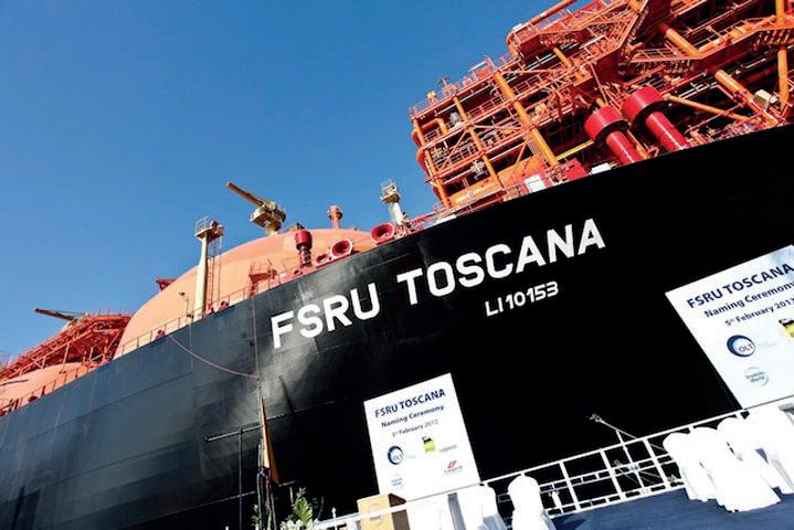
Figure 1. OLT’s FSRU Toscana.
Ammonia storage systems carry significant consequences, making thorough inspections crucial. Determining the right inspection strategy for a particular tank can be difficult when balancing inspection techniques with any identified damage to date and potential damage mechanism propagation. With E²G | The Equity Engineering Group, Inc., you can gain confidence in your ammonia tank inspection strategy and frequency. Our comprehensive approach enhances confidence in inspection results, empowering you to make informed decisions.
E²G delivers a multi-disciplinary approach that leverages API 581 risk-based inspection (RBI), European Fertilizer Manufacturer’s Association (EFMA) qualitative RBI, advanced probabilistic analysis, and finite element analysis (FEA) to offer a better understanding of the expected probability of failure.
Choose E²G for an optimized ammonia tank inspection strategy that is focused on safety and reliability.
SERVICE AREAS
⊲ Risk-Based Inspection (RBI)
⊲ Tank Fitness-for-Service (FFS)
⊲ Damage Mechanism Reviews
⊲ Finite Element Analysis (FEA)
⊲ Structural Analysis
REDUCE RISK OF UNEXPECTED FAILURE INCREASE
an understanding of how best to handle them. Other benefits included determining the operating rules for small-scale LNG.
Another example of an FSRU where digital RAM tools have been introduced is Offshore LNG Toscana’s (OLT) development in Italy. In April, it was announced that the facility would be at 100% capacity until 2027. The regasification capacity of 3.75 billion m3/y, which is currently authorised, was offered in LNG slots of 155 000 m3 (per cargo).
For the Italian energy system, it is one of the country’s most important infrastructure developments for the import of LNG. It is permanently moored around 22 km from Tuscany, on the coast between Livorno and Pisa.
To assess the risks and challenges faced by OLT’s FSRU, a range of parameters that have an impact on the overall system performance over its lifetime were assessed. This enabled all stakeholders to agree on terminal performance guidelines and associated contingency plans.
The relationship between terminal send-out efficiency and gas import volumes was quantified, where it was demonstrated that efficiency is heavily reduced with increasing import requirements, mainly due to lower levels of equipment sparing at the FSRU as throughput increases. The design configuration of the LNG topside facilities was optimised and overall performance improved as key
performance drivers and bottlenecks in the terminal were identified and addressed.
The TARO models were also used to identify the significant operational and financial risk posed by LNG delivery schedule congestion, as a result of berthing slot disruption and tanker delays. As mitigation, the proposed ship sizes and storage volumes on the terminal were optimised to find acceptable trade-offs between demurrage hours, zero send-out time and efficiency.

In the last 12 months, DNV has applied its digital RAM tools in support of numerous FSRU projects, working with vessel designers, owners and grid operators to improve performance and maximise the value of their LNG assets. These essential projects are expected to contribute significantly towards their nations’ future energy needs: 8.5% of Germany’s future gas requirements will be met via the Wilhelmshaven import terminal, whereas the regasification capacity provided by multiple FSRU developments in Italy will represent around 20% of their demand.
Security of supply is the overarching aim but to get there, challenges must be understood and de-risked.
LNG supply chains are subjected to numerous potential hurdles, including terminal accessibility, coordination between shippers, equipment reliability issues, etc. However, RAM digital tools enable risk management decisions to be taken to foster a sustainable and resilient energy future.
The liquid commodities market is in a state of rapid growth. Exporters are expanding their operations to send LNG, as well as new types of low-carbon refined products and biofuels, from countries such as the US and Europe into South America and Asia.
Simultaneously, crude oils are being imported to and exported from the US, while other critical feedstocks are imported to the US, Europe, and many other countries. As the market increases, the demand for terminals is growing. Large companies are acquiring existing terminal facilities, and venture capitalists are supporting greenfield projects by building new facilities around the globe.
Rapid growth and expansion can bring massive returns, but it can also present problems if organisations are not prepared. As companies introduce new products into their terminals and acquire new assets – or even attempt to do more with what they already have – they must find ways to optimise those assets to expand operations without needing to grow or overtax their workforce. To accomplish this, forward-thinking organisations are turning to digitalisation by using software to increase throughput and efficiency –ultimately increasing standardisation, safety, and performance while simultaneously delivering higher profitability.

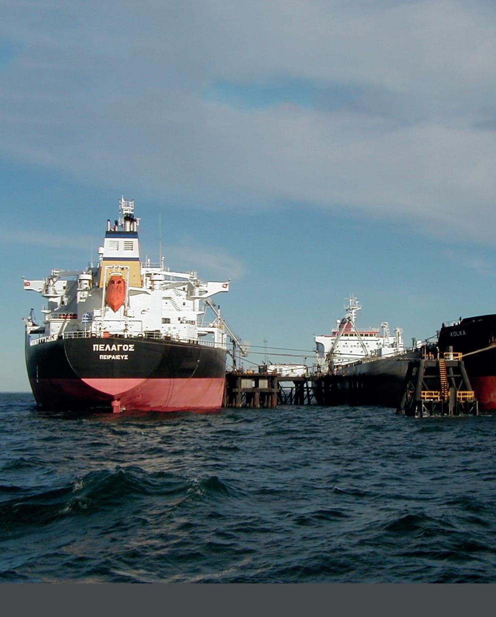
In large ports around the world, the many vessels coming and going can choose a wide variety of terminals. The companies operating those vessels make decisions based on their own business objectives. They will select facilities that have a reputation for efficiently offloading their product, protecting it, and moving it through the terminal as quickly as possible. Doing so means more sales for their product, whether it comes from their own refineries, pumping stations, or other sources.
If one terminal can turn a vessel around in 12 hours and another takes 18, this time difference will be a significant factor in facility choice, as customers can use the extra time to turn their vessel around, get more product into it, and send it elsewhere. Increasing business often means capturing that time deficit, because terminal efficiency helps customers meet their own objectives.
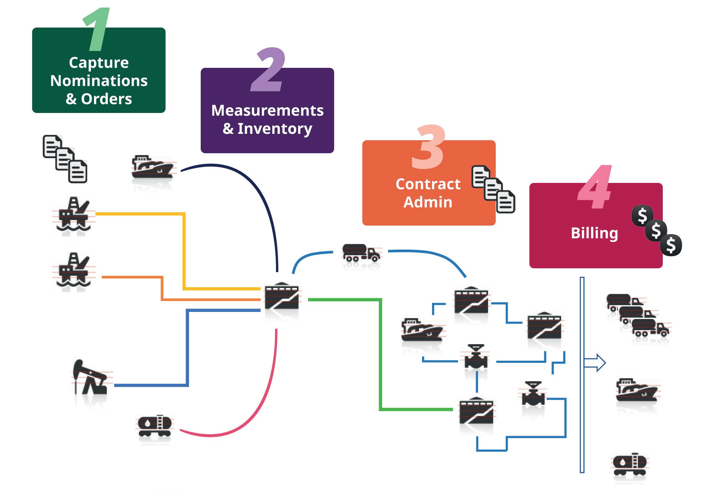
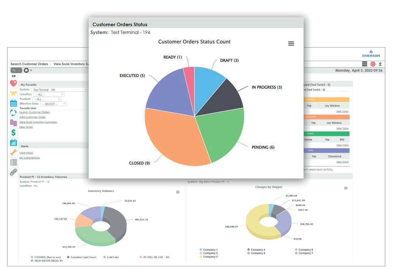
To capture that difference, a facility needs to maximise its known throughput capacity. Downtime or slow time in operations leads to decreased throughput, making a facility far less competitive. Today, many organisations are eliminating downtime and slow time by implementing order-to-cash software, which digitalises operations by collecting the information surrounding a customer’s order for the movement of product into, out of, or within the facility.
As the movements occur, the software automatically creates a movement ticket, providing visibility of the entire process, while tracking customer inventory by terminal, tank, or product. Following the completion of the movement, the software updates the contractual service charges, including leasing of tanks, the throughput itself, and even ancillary services, such as heating tanks and line flushes (Figure 1).
Kevin Niles and Sandy Tiu, Emerson, USA, explain how choosing the right software can drive dramatic improvement in terminal operations, increasing efficiency and delivering return on investment.
Although software tools, such as order-to-cash applications, have existed for some time, many organisations are just getting started on their digitalisation journey. The value of traditional investments, such as those into hardware and safety equipment, are easy to understand, as they are necessary to move product and protect personnel and the environment.
However, software investment is just as important. Once a team has a vision and an automation software solution in place, the terminal – or even a series of terminals - can operate as a cohesive, interconnected ecosystem for increased efficiency. With order-to-cash software in place, teams know what to move, where to move it, and how to do so, while minimising contamination and time-consuming line flushes. The terminal will increase throughput and optimise facility operations so that product moves faster for customers.
Embracing such a digitalisation vision leads to dramatic improvements across the facility and, potentially, across the enterprise.
At its most basic level, order-to-cash software helps an organisation improve visibility across the facility. A complex network of pipes, valves, and tanks dominates any terminal, and finding a way to navigate that web takes time and expertise –two things that are often in short supply. In fact, scheduling these transactions is one of the leading causes of excessive downtime and slow time in terminal facilities. Teams scheduling transactions manually often take too long to stop one process and start the next.
For example, teams often must flush lines to facilitate product movement without contamination. The flushing process can easily take hours, which is downtime where the terminal is not generating revenue.
Order-to-cash software can automatically plan movements so that they pass through the most efficient routes without mixing products. Built-in algorithms track the products, bringing in a batch, splitting it into different pieces, and moving those pieces through different tanks – avoiding mixing where necessary, and automatically mixing where desirable. Movements are optimised to make the most of every hour of each day, and they are automatically tracked all the way back to the original batch, so that operators have a complete, reliable paper trail for auditing.
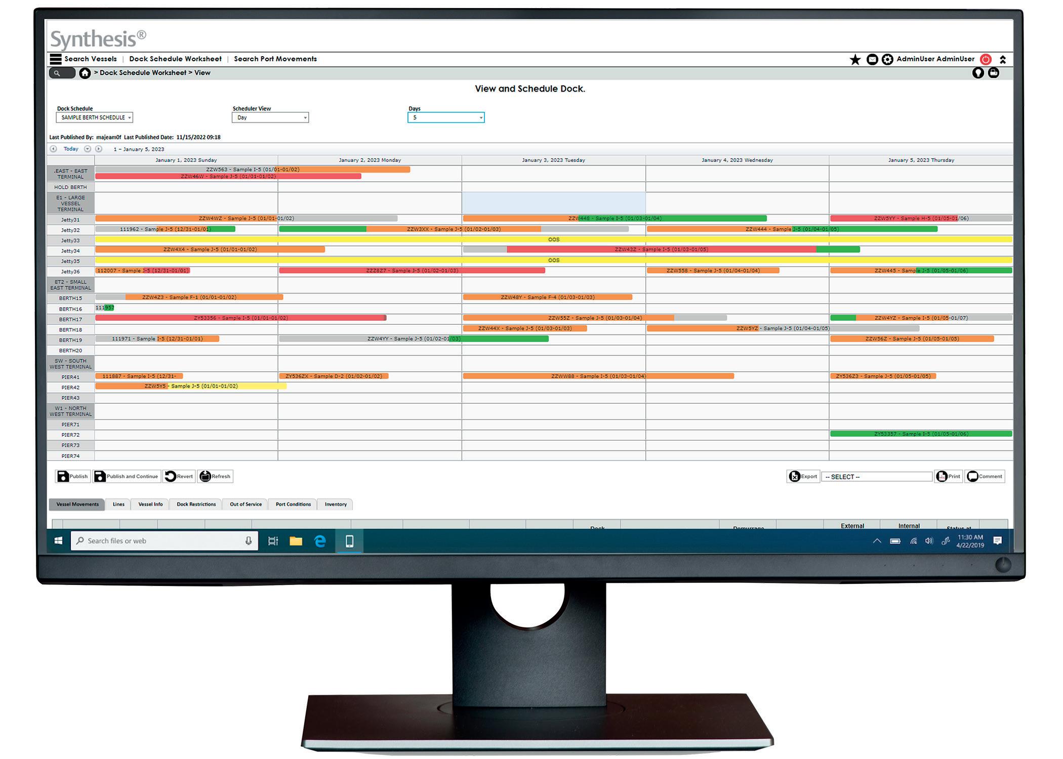
Because actions are recorded in near real-time, operators have continuous visibility of what is happening across the facility, helping them to make better decisions. With cloud connectivity, these reports can be made available securely and remotely, helping members of a lean staff monitor their critical activities from anywhere, empowering them with more mobility and easier collaboration (Figure 2).
However, improved visibility does not stop at the facility level. Easy scalability enables an organisation owning a series of terminals in different parts of the world to still view them within a single instance, hosted in the cloud or on premises. Digitalisation tools support a boundless automation vision where teams eliminate data siloes and enterprise personnel can see everything that is happening across their fleet from a single view, from anywhere. Enterprise teams can monitor inventory or follow up on problems as they occur. Transactions are updated in real time in the system, from ordering and processing, all the way to invoicing, and everywhere in between.
With the most advanced order-to-cash software and the required connectivity, organisations can even extend visibility to their customers’ customers. A customer can instantly see how much inventory it has and where it is, so that business decisions can be made about how and where to ship product.
Every region has unique elements to its operations, and fit-for-purpose digitalisation solutions will take these nuances into account. For example, European operations must navigate the complexity of customs clearance as products are exported and imported between countries.
Using manual processes, customs delays are a common occurrence. Between phone calls, faxing and emailing,
Chart’s LNG power generation solutions provide natural gas to hundreds of thousands of homes. This is one way Chart facilitates LNG as a safe, clean-burning fuel for energy, transportation and industry.

documents can easily get lost, thus causing delays. If customs processes are delayed, vessels are stranded. Those stranded vessels block other vessels trying to move in or perform operations, ultimately creating a chain reaction that leads to missed deadlines and confused schedules for both the terminal and its customers. In the worst scenarios, that chaos can lead to demurrage that can generate tens of thousands of dollars in fees.
Order-to-cash solutions streamline the customs process through business-to-business connections with the customs authority. As a batch is processed through a terminal, order-to-cash software can process the customs application and automatically submit the data to the proper customs authority.
Customs can then digitally return clearance, at which point the order-to-cash software automatically updates status and documentation, allowing the vessel to depart whether clearance was granted in the middle of the afternoon or the dead of night.
Other complexities can be tied to product types. For example, transporters of LNG need the flexibility to track product in different ways, including both volume and calorific value. The most advanced software solutions can convert from mass to volume to British thermal units in support of liquefaction and regasification.
In any terminal, when product is moving from tank to tank, or moving out of the facility, teams need to follow essential safety precautions. In fact, any time the team operates a pump or opens a valve, a series of safety protocols must be followed. Safety procedures typically consist of a checklist of operations to perform critical tasks safely, and those checklists must be monitored by supervisory personnel, often needing sign-off. Many operators are still performing these tasks on paper, which not only leads to inefficiencies in the process, but also risks creating safety hazards due to oversights.
Terminals can dramatically improve their safety and efficiency through digitalisation, taking advantage of the automated safety tools built into order-to-cash software.
Using a supported and intrinsically safe handheld device, operators and technicians can perform safety checks in real time, and those checks – and their results – will be instantly available to others in the facility.
Supervisors can oversee operations from anywhere, and they can sign off digitally to ensure operations are not interrupted because a critical person is off duty or hard to find, for example. Moreover, those same safety reports can be instantly and automatically transferred to the enterprise, where personnel can use the data to track and trend safety and reliability issues across the whole fleet.
One terminal operator needed to improve visibility and efficiency for servicing a customer that was sending hundreds of trucks into the terminal each day to lift petrochemical products. The company only had two customer service representatives, and needed a way to streamline the transaction process to move product more efficiently and effectively.
Using its order-to-cash software, the terminal was able to use application programming interfaces to connect directly to the customer’s enterprise resource planning software to create a round-trip business-to-business software system for faster transaction processing. Today, the customer simply submits hundreds of truck lifting orders electronically on a daily basis.
The automation software at the terminal then schedules and executes the process. Once the operation is complete, an invoice automatically goes back to the customer to let them know what was moved and how much it cost. The entire process is hands-off, and the terminal operator can easily complete all operations with their lean staff.
Such an automation configuration is advanced but is also entirely possible – especially when terminal organisations work closely with a trusted automation partner to select and implement order-to-cash solutions. Even after the software is live, a trusted partner can continue to support customers, for example by helping a terminal operator set up new contracts, along with automation that has never been attempted before, helping customers to stay nimble and efficient, even as operations change (Figure 3).
Moreover, software and cybersecurity continuously evolve. The best automation suppliers will regularly update their order-to-cash software with new features to improve cybersecurity and functionality.
Digitalisation of a terminal’s processes is about more than simply implementing software and technology; it requires a mindset change. A terminal can continue to run the traditional way –emailing records, manually scheduling transactions, and keeping individual terminals siloed from each other. However, the organisations that will best compete as the industry evolves with newer products and increased economic pressures will be those that implement software solutions to help them better manage efficiency and maximise throughput.
Just as with operational and safety equipment, software is an investment, but it is one that will pay significant returns in the decades that a terminal operates, not only through increased revenue, but also in improved goodwill and loyalty from customers.
Automation and control systems used in terminal facilities have evolved to keep up with asset owner and operator requirements to ensure facilities operate reliably and at full capacity. Over the years, systems have migrated from pneumatic control to single loop control, to vendor proprietary systems, to current systems running standard off-the-shelf hardware and operating systems that resemble information technology (IT) systems yet have a completely different mission. Current operational technology (OT) systems are now susceptible to cybersecurity attacks. Data sharing between IT and OT has increased as companies have strived to optimise their systems and increase profit. A strong dependency now exists between IT and OT, where pipelines, tank farms, and terminals rely upon business IT applications for inventory and accounting to ensure molecules are tracked and billed accordingly. When IT is impacted, the business may not have the capability to fall back to manual tracking methods to operate their OT systems. A recent example of these dependencies was highlighted in February 2022, when OilTanking in Germany, SEA-Invest in Belgium, and Evos in the Netherlands all suffered a cybersecurity attack on IT systems
that impacted their ability to operate their OT systems at a normal capacity.1
Cybersecurity events can devastate corporate profits, especially when organisations are unprepared to react. The public perception of a company that falls victim to an attack can be impacted, but more importantly, it is the loss of revenue, impact to employee safety, and damage to the environment that are of the utmost concern. As an example, the shipping company Maersk lost an estimated US$200 - 300 million in the NotPetya ransomware attack alone, not including unknown upstream and downstream supply chain losses.2
Colonial Pipeline suffered a ransomware attack in 2021 on its IT systems. To save its OT environment from a similar fate, it performed an IT to OT disconnect, isolating the pipeline SCADA from the business accounting systems. This decision eventually led the company to stop its US east coast pipeline operation due to the inability to account for product ownership along the pipeline and in tank farm inventories and customer billing. To resume operations, Colonial paid nearly US$5 million to the threat actors to recover its ransomed IT systems, but the effects could be felt nationwide with finished product prices increasing.

Mike Hoffman, Dragos, USA, examines the different cybersecurity threats that face the tank industry, and what actions can be taken to mitigate this.
However, this was felt the most on the eastern seaboard as fuel stations quickly ran out of supply.
Governmental response to these cybersecurity attacks has brought about regulation and cybersecurity baseline practices, such as the US Transportation Security Administration’s Pipeline Security Directive (SD02C), requiring pipeline owners and operators to establish a cybersecurity implementation plan, assessment plan, and develop and test an incident response plan.3 Similarly, asset owners and operators of essential services in EU Member states under the NIS2 Directive have several baseline security controls and policies, including incident reporting requirements.4
Resources, budgets, and outage time constraints are universal limitations at terminal facilities. Therefore, security controls cannot be applied to all systems in the same way or at the same frequency. Given an increase in cyber threat to the landscape, cybersecurity should be viewed as a business enabler to ensure safe, reliable, and optimised operations. Therefore, critical systems that need security controls include but are not limited to:
n Inventory tracking.
n Distributed control systems (DCS) or programmable logic controllers (PLC).
n Terminal management systems.
n Tank measurement and tank strapping tables.
n Custody transfer flow meters and meter factor numbers.
n Online/offline analytical measurement (methods and calibration data).
n Electrical switchgear and motor variable frequency drive (VFD) controllers.
Whether organisations are just starting on their cybersecurity journey or have a mature cybersecurity posture, knowing how to focus efforts and monies appropriately is the topic of many leadership conversations. SANS, an IT and OT security training provider, recently outlined the five critical controls that organisations should focus on to secure their OT environments.5
The controls are:
n Incident response plan.
n Defensible architecture.
n OT network monitoring.
n Secure remote access.
n Risk-based vulnerability management.
The first and most important thing that organisations can do is to be ready for cyber-attacks against their company’s critical automation and control systems. When ransomware strikes, or equipment begins to misoperate, operations, engineering, and technicians often struggle to understand what is happening. In today’s adversarial cyber landscape, companies must have a documented incident response (IR) plan. This should be the first call to action if an organisation does not have an IR plan in place. To start, a documented plan for a ransomware attack scenario should be included. Focus should be placed on when an IT/OT disconnect would take place, understanding what systems would be affected, who would need to respond, who would need to be notified, could the OT systems work while IT systems are
disconnected, etc. The IR plan should answer these questions and be a guiding light in the dark hour if the company does fall victim to an attack.
The next area that a tank farm/terminal facility should focus on is ensuring that the network architecture is designed to protect critical OT assets from IT networks and then further segment the OT systems into areas of trust or security zones. If a system does not need to communicate with another system, then technical controls (e.g., firewalls) should be in place to prevent those communications from occurring. OT systems are commonly classified based on the type and relative process data timing needs from real-time to aggregated time, and then the systems are segmented according to zones. Sitting between the OT and IT networks is a demilitarised zone (DMZ) construct that acts as a traffic gateway to ensure that user-to-system and system-to-system communication crossing the OT to the IT environment, or cloud, is brokered and tightly controlled. The DMZ also provides a logical area to isolate the automation systems in the event of a cybersecurity event on the IT side. DCS and PLC systems logically reside within the OT environment. Still, terminal management systems and quality measurement systems (online and laboratory analysers) are often overlooked and reside on IT networks in many organisations. These systems are critical and should be in a secure zone on the OT side.
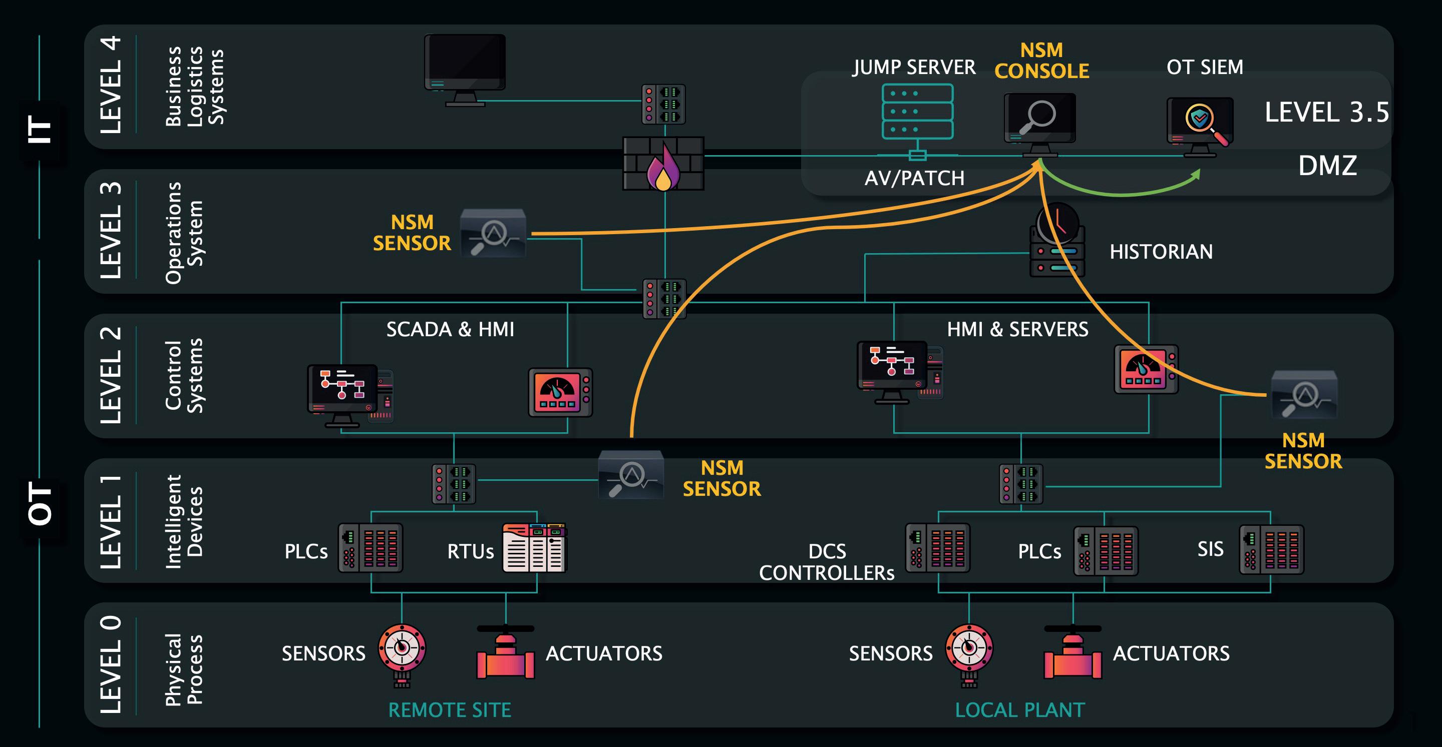
Setting up a well-architected network not only prevents cybersecurity attacks from occurring but allows for security monitoring solutions to be leveraged in the environment. Unlike IT systems, where software agents can be deployed on all workstations and servers, OT systems are engineered and often restricted by vendors as to what security software solutions can be deployed. OT systems have many devices, such as DCS controllers, PLCs, remote terminal units (RTUs), flow computers, analysers, and instrumentation, that cannot run conventional security software. Nevertheless, asset owners and operators must understand the activities that are occurring on the networks. Deploying continuous network security monitoring (NSM) solutions provides valuable insights into the overall operation of automation and control systems. For example, NSM can detect workstation-to-server or server-to-controller traffic and further see commands being sent to devices, such as when a variable frequency drive (VFD) motor driving a product pump is commanded to increase flow into a pipeline. They will also be able to detect malicious behaviours, such as an adversary trying to jump the IT to OT boundary to move down into the OT environment further to compromise systems with the end goal of system disruption or damage. Detecting at the IT/OT boundary and near PLC or DCS traffic is critical to a holistic security programme. NSM also dramatically assists with identifying device and network misconfigurations or leading indicators to failures, thereby simultaneously providing operational reliability and security benefits. Figure 1 shows a high level NSM deployment diagram.
Many terminal facilities do not have sufficient size or complexity to warrant onsite control systems engineers, instrumentation and
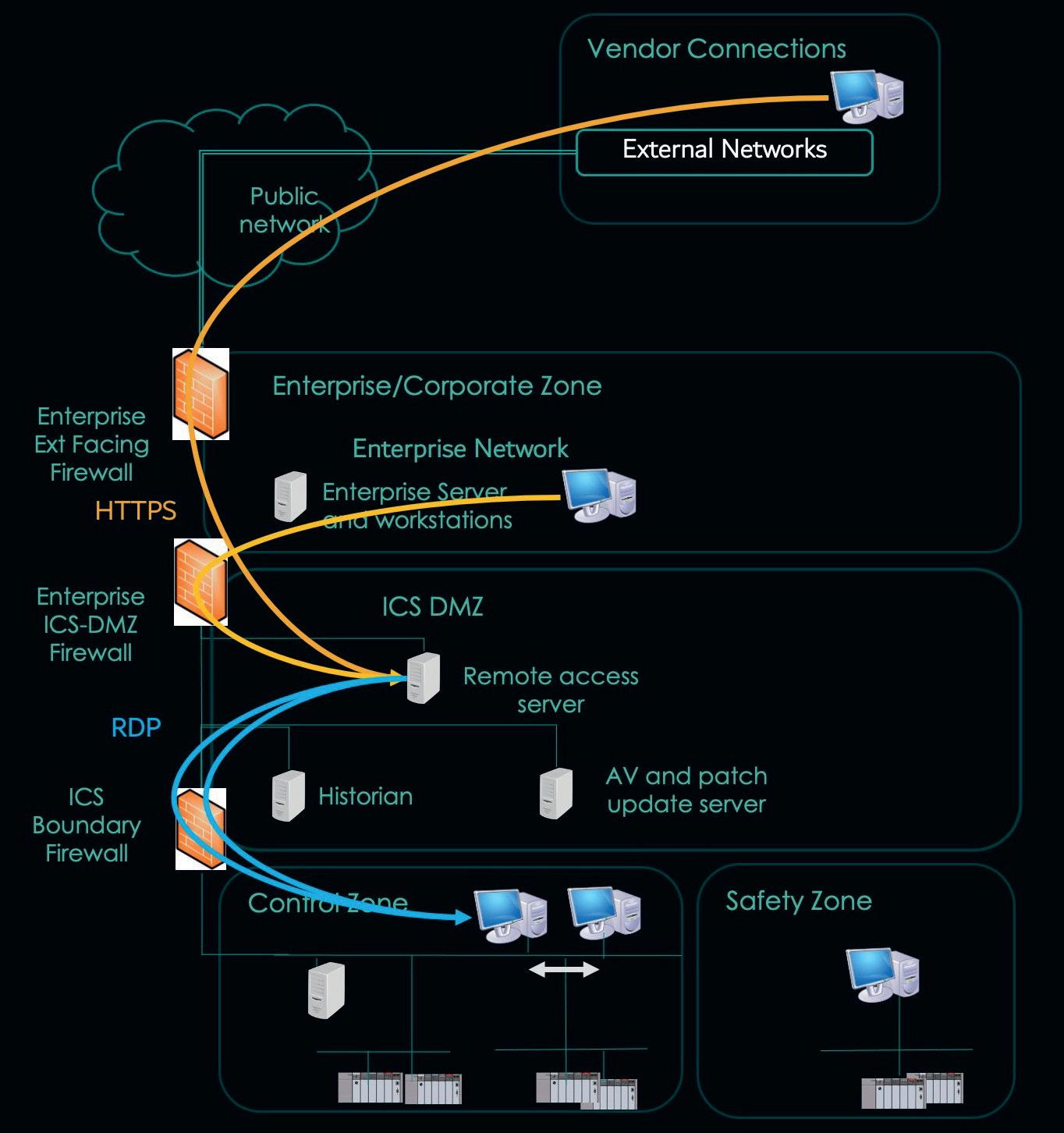
electrical (I&E) technicians, or OT security staff. Often these individuals cover a region encompassing many terminal facilities. However, these distributed roles still need access to the automation and control systems to support operational troubleshooting and even make small changes in logic or control strategy (onsite presence is still advised or required to make process impactful control system changes). Remote access solutions provide the necessary technical means to allow these workers to access the plant. These solutions must reside within a secure zone between the IT/OT DMZ and ensure a network protocol break occurs between network communications coming into and out of the remote access server to the facility system being accessed. As Figure 2 shows, an initial connection occurs over HTTPS to the remote access server from the IT side. Then the remote access server establishes a remote desktop protocol (RDP) connection to a terminal OT server or workstation.
The remote access solution should enforce a second form of authentication, often called 2FA, that leverages a token or one-time password. 2FA drastically raises the difficulty bar for an adversary to break in and should always be used in remote access solutions. This solution can be used for both in-house and vendor-supported remote access.
Automation and control systems are comprised of firmware, operating systems, and applications. Unfortunately, they are susceptible to many of the same vulnerabilities on IT systems. For OT servers and workstations running Windows, these devices need to be patched on a determined frequency. Other systems, such as the DCS or PLCs, also need to be kept updated, but often less regularly due to the operational impact of applying a patch or firmware that requires rebooting the systems. A recommended approach is to inventory systems to know what you have and to understand what needs attention. The NSM solution mentioned previously will significantly help this effort. It is also important to apply patches and firmware based on factors such as the interconnectedness to the IT environment, operational risk, and operational impact of the patch itself. Other mitigating controls also play a part here, such as restricted network access through segmentation or disabling vulnerable functionality. For example, if a PLC sits alone on a skid with no network connection, it will fall into a very low-risk category. Increasingly, however, automation systems are networked to support remote monitoring and control. Requirements for increased patching frequencies grow for remote access, data, and file transfer servers or those interacting with the IT and business systems.
In the current heightened cybersecurity threat landscape, terminal facilities and tank farm operators can fall victim to ransomware or even worse. Organisations must prioritise
protecting their critical assets with attacks focused on damaging equipment, employees, and the environment. This includes having a plan that allows OT systems to operate and generate revenue when IT systems are taken offline. Critical systems need to be defended, and by applying five critical controls, owners and operators will be in a much better position to take the higher ground against adversaries trying to bring the company down and stop the transfer of molecules.
1. TIDY, J., 'European oil facilities hit by cyber-attacks', BBC, (3 February 2022), https://www.bbc.com/news/technology-60250956
2. LORD, N., 'The Cost of a Malware Infection? For Maersk, $300 Million', Digital Guardian, (7 August 2020), https://www.digitalguardian.com/ blog/cost-malware-infection-maersk-300-million
3. https://www.tsa.gov/sites/default/files/tsa_sd_pipeline-2021-02july-21_2022.pdf
4. https://eur-lex.europa.eu/eli/dir/2022/2555/oj
5. LEE, R. M., and CONWAY, T., 'The Five ICS Cybersecurity Critical Controls', SANS Institute, (7 November 2022) https://www.sans.org/whitepapers/five-ics-cybersecurity-critical-controls/
Figure 1. OT network security monitoring deployment.
It is unlikely that Tacitus, one of the great Roman historians, had the future ‘inspectability’ of production hydrocarbon tanks in mind when in 110 AD he stated: “Truth is confirmed by inspection and delay; falsehood by haste and uncertainty.”
But his comment is just as apposite in 2023. And just as this article is focused on the floating offshore production environment, and the inspection of tanks, then so too is its applicability to other safety-critical asset integrity areas of operation.
In many ways the disruptive technology environment in which regulators and inspection companies operate today exacerbates rather than solves the challenges faced by those interested in ‘inspection’, seeking the ‘truth’ and reducing both ‘falsehood’ and ‘uncertainty’.
Artificial intelligence (AI) brings, and will continue to confer, truly game-changing and welcome technology benefits. It does, however, have the demonstrable propensity to be used unethically to project fake information, to promote inaccurate data, and to amplify false insights. The wise must pause to reflect on its application, especially where safety and the integrity of assets might be at stake. Ironically, the rise of autonomous and thinking robots may undermine the crucial human interface; where trusted human teams underpin the integrity of data and where the strong and binding relationships between clients, suppliers and the regulators assumes an even greater importance than it does today.

The COVID-19 pandemic was a truly terrible period for humankind, in which the ripples extended way beyond the suffering, death and disruption. As industry sought to find ways to continue to trade and to be productive, remote working and associated technologies came to the fore, providing a key boost to innovation in so many areas including remote inspection technology (RIT).
The changes also had unwelcome and unintended consequences. For many, remote working brought positive changes to the balance between work and life. But many employees now appear reluctant to change or to return to the former status quo. ‘Quiet quitting’, where staff do just enough to retain their jobs, is on the rise. ‘Overemployed’ workers secretly maintain two remote jobs at the same time, ensuring their employers remain unaware. These phenomena are on the rise, and evidenced by the plethora of support groups and online apps that support this new way of working.
All of this has increased the notion of ‘distance’, added uncertainty, and consequently made true accountability and responsibility all the more opaque. Workplace remoteness appears to have brought with it increased managerial remoteness with many seemingly reluctant to take accountability for the integrity and safety of the assets for which they are responsible.
Assemble these factors and influences and a picture begins to emerge. Paradoxically, RIT and all that it does and can do to dramatically improve safety, reduce risk, and reduce human exposure in dangerous confined spaces, may increasingly have its effectiveness reduced by the enabling technologies that are underpinned by AI.
As artificial intelligence (AI) brings unparalleled change to the storage sector, Danny Constantinis, EM&I Group, Malta, outlines the importance of accountability at all levels within the sector.
The presence of ‘trust’ could be eroded by a growing lack of accountability arising from the pernicious effects of remote working and the growing distance between those accountable for safety and those responsible for it.
If the tanks and terminals industry is to realise its desire to reduce accidents and improve safety, especially in dangerous confined spaces, it might appear there are four options:
This would reduce the challenge faced by those seeking to deploy RIT systems. One obvious way to achieve this is to design-in ‘inspectability’ early in an asset’s design life cycle where it is practically possible to do so, and where significant cost benefits may accrue. It is becoming ever easier to design and develop high performance components with little regard for their inspectability. As an example, EM&I has worked with a number of clients seeking to realise the cost and safety benefits of installing its ODIN access ports during FPSO conversion projects. These access ports are fitted inside the hull during operations (without disrupting operations) to perform a range of tasks that previously required a risky, expensive and time-consuming intervention by dive teams. The ODIN access ports permit valve inspection and, frequently, valve isolation and repair, as well as sea chest inspection.
There are self-evident benefits to using an ODIN access port to facilitate diverless inspection and repair scopes of mission-critical valves and sea chests. Inspections are carried out from inside the hull so there is no dependency on weather or sea state and associated costly downtime. It is significantly safer than using divers and a far lower cost than using either divers or remotely operated vehicle operations. The high-definition video and still imagery provides excellent inspection output for Classification Society (class) approval,
including close-up inspection of the valve sealing faces. The benefits are amplified significantly when the ports are designed-in early, and installed in the shipyard; rather than retrospectively and while on station.
The advent of reliable sensors that are capable of seeing through the sludge and dirt inherent in a production oil tank remains a vital aspiration. Until that time, RIT will continue to require that tanks are prepared for inspection. It is crucial that tanks are cleaned to the standard defined by the Classification Societies if RIT or a Class Inspector is to be able to effectivley inspect bottom plating. It must be incumbent on those Classification Societies to insist that the cleaning standard is maintained.
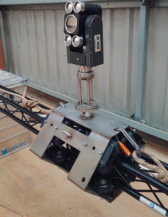
Owners and operators should embrace the possibilities offered by RIT from the outset. Companies that pride themselves on understanding the needs of their clients, and seeking innovative solutions to those challenges, depend crucially on the willingness of owners, operators and regulators to adapt. Recently, for example, EM&I has extended its RIT capability within the dangerous confines of offshore cargo oil tanks. Early versions of EM&I’s high-definition camera systems for general and close visual inspection, and its laser sensor for assessing deformation coating condition, and corrosion, depended on the use of robotic quadpods to be delivered vertically through small deck openings such as Butterworth hatches. Its recent deployment of an innovative ‘bridge system,’ delivered through the same small openings, now permits robotic lateral movement of sensors inside the tank so that the spread of the inspection footprint now fully matches that which a Classification Society might want inspected, including the vulnerable under deck area.
AI is being seen in some quarters as one of the most significant global threats to national security and global stability through its unethical use to portray situations that in reality do not exist. Those promoting this theory believe the solution lies in trusted teams of humans in each country that know each other well and trust equivalent teams in other nation states to broker stability between nations. There may be a parallel in our industry where there will be merit in promoting and providing organisational structure to the human interface at key levels in clients, owners, operators and regulators to promote the reliable passage of reliable, accurate and timely asset integrity data.
Rightly, advances in AI will and should prevail; they will bring unparalleled and welcome change. For those whose responsibility includes safety, inspection and asset integrity of high-risk assets in challenging environments, AI does bring a raft of concerns which need to be addressed sooner rather than later. Before that, a return to insisting on true accountability at all levels in the industry will go a long way to providing the safe environment that we all see.
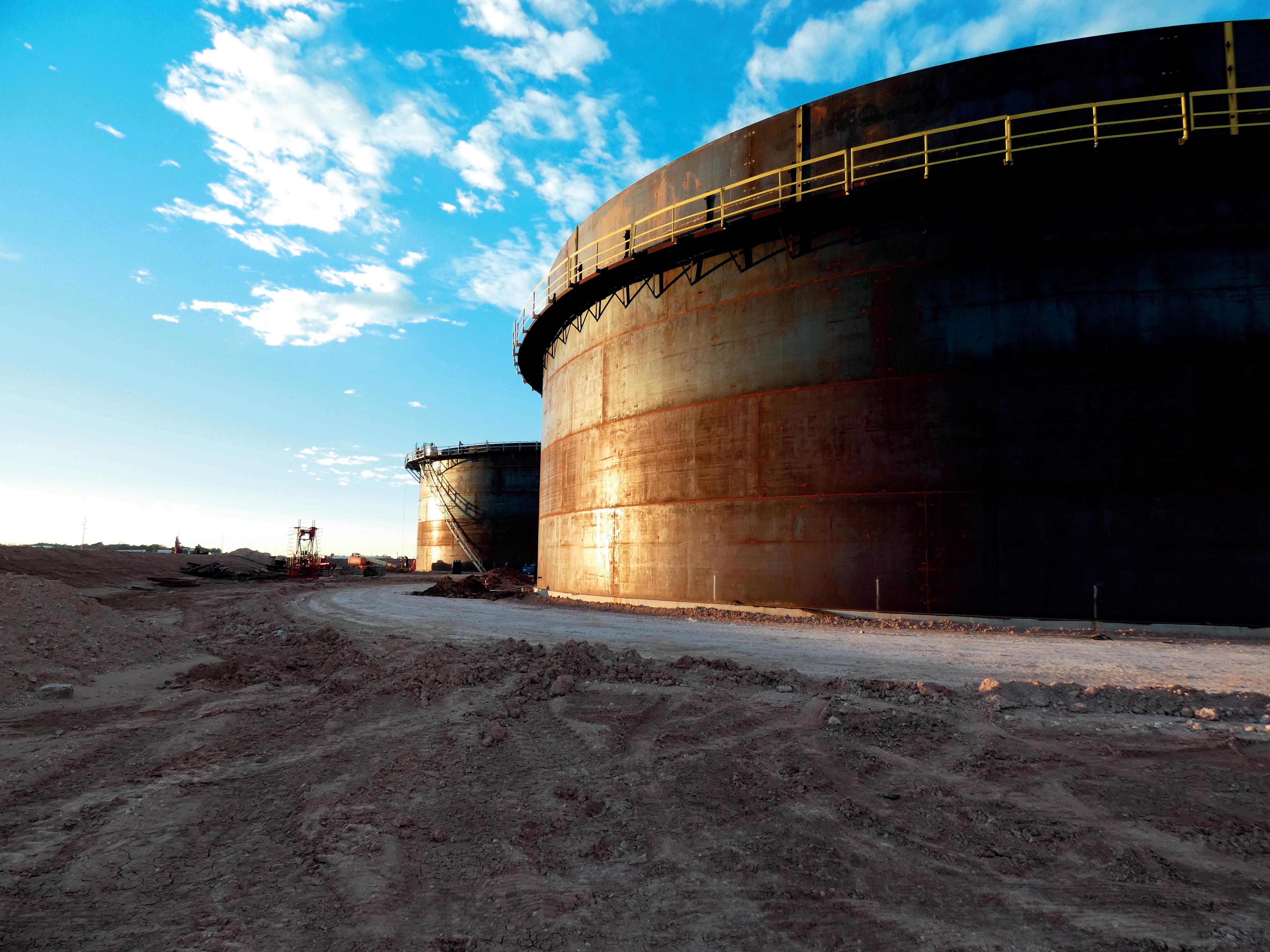
Tanks are built to operate for many years and need to be inspected, maintained and repaired periodically to be safe and efficient. Every storage tank will accumulate sludge over time and this is especially true for petroleum storage tanks at terminal facilities. Contaminants such as wax residues, organic matter, shells, aggregates, and water can affect the quality of the product in the tank and can corrode its floor and inner walls. It can also cause damage to floating roofs and prevent them from providing a tight seal. If residues or sludges are not removed for a considerable period, they can occupy significant space in the tanks, therefore reducing capacity

within the tank and altering the quality of the product stored within the tank.
The solution to this issue is the extraction of this sludge and the cleaning of the tank itself.
When deciding on the cleaning method to be applied, terminal operators will take into consideration the most efficient, safe, economical and environmentally friendly cleaning process available to them.
Up until recently this process would have involved personnel manually cleaning the interior of the tank. Manual tank cleaning involves a team physically scrubbing the contaminants from the surface of the tank. These workers are exposed to a multitude of hazards that have historically led to injury and even death when control of activities has been lost.
With the advance of remotely-operated, explosion proof robotic cleaning equipment, the presence of people inside the tank is unnecessary.
In terms of cleaning cost and environmental impact, ATEX Zone 0 robots are economical and environmentally friendly because of their closed loop cleaning circuit, leading to the potential to reclaim precious oil from the sludge.
Robotic cleaning methods are highly efficient as tank downtime can potentially be reduced by 40% up to 70%, due to the short time it takes to assemble the equipment and the fact that staff are not required to enter the confined space of the tank.
As the industry embraces change and introduces innovative technology onto sites to replace dated methods, terminal operators are profiting from major operational benefits in safety and a significant reduction in the downtime of the tanks. There is a focus on employing cleaning methods that consider personnel safety, cleaning efficiency, time and money savings, as well as the protection of the environment.
Oil terminal operators are focusing on recovering the oil contained in the sludge residue as the revenue generated from the recovered oil could go some way to
cover the cost of the cleaning operation, and robotic sludge removal promotes this.
Before cleaning a tank, the composition of the sludge must be considered, to determine the cleaning process required. It is important to understand the composition for the recovery of oil, the treatment of the wastewater, and the solid residues and toxic substances to be removed and disposed of.
When a tank is scheduled to be cleaned, terminal managers create a planned schedule for the scope of work. The main parts of the plan relate to the safety of staff, the environment and the terminal assets. The project, cost, scope of work and execution time is planned and agreed before any activity occurs so that the safest, most efficient process can be adopted.
Should a terminal manager choose to have the tank cleaned manually, there is a major body of work to be completed before anyone enters the tank. Tasks including confined space entry plans, updates on the methodology of the project, safety lessons for personnel, and the organisation of construction around the tank all must be completed.
Prior to a manual clean, the tank must be gas free, for the safe entry of staff. Gas must be extracted from the tank and all manholes, cleaning doors and apertures on the roof are opened. The process can be accelerated using fans which are fitted to increase the supply of fresh air.
Manual tank cleaning can be criticised because of a multitude of disadvantages, including the following:
n Tank downtime is significant.
n System installation time and auxiliary cleaning equipment is required, such as water jetting, pumps, vacuum trucks, shovels, cranes, tool warehouses, containers, portable dressing rooms, toilets, restaurants, and offices.
n Time taken to ventilate the interior complicates the job further, thereby adding to the cost and the demad of resources.
n Time taken to be certified by the appropriate department can also be significant.
n A large water supply is required.
n Quality of the cleaning is low.
n Cleaning efficiency is low.
n Open circuit to the environment, which presents a high risk of petroleum wastes contamination.
n Cost due to the number of cleaning staff, observers, rescue teams and safety officers.
n Workers must wear heavy personal protective equipment (PPE) with breathing apparatus.
n The job requires the manual removal of toxic sludge.
n High amounts of waste (water, oil, and sludge) are generated and need to be disposed of.
n Significant use of equipment and manpower is required.
Health and safety regulators’ concerns also apply during the execution of manual tank cleaning, downtime can be considerable, and skilled workers for the job are limited
and difficult to find due to the ageing of the workforce in this sector.
All of these components can add to the cost impact, making it more expensive than the mechanical cleaning cost.
The demand for a safer method of cleaning for humans, the environment, and the terminal facility itself has given rise to robotic tank cleaning services with a mission to eliminate human entry in hazardous confined spaces and avoid exhausting manual labour.
Robotic tank cleaning does not require the presence of humans inside tanks as the robot is controlled from an independent control unit outside the tank. The robotic equipment is housed inside a truck and is easily transported on site.
The remote-controlled robot enters the tank using a hydraulic ramp and breaks up and removes tank bottom sludge using an auger system located at the front of the robot which breaks down heavy sludge. This is all without the requirement to use water. All equipment is explosion proof with cameras and LED lights fitted onto a collapsible arm, allowing it to fold when entering the 600 mm tank manyway.
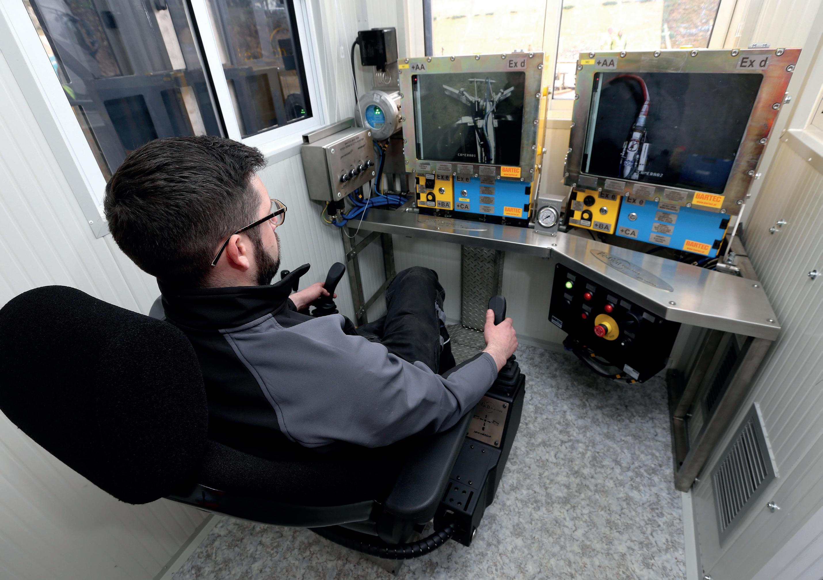
The robotic operator manages all aspects of the tank clean from a dedicated, air-conditioned control room through the series of cameras and gas monitoring equipment. This ensures every clean, no matter what category of tank, is uncomplicated as the operation is remotely controlled with permanent visual connection.
Only three people are required for installation, and this can take as little as four hours without the need to hire cranes, as cranage is contained within the unit.
The vehicle enters the tank manhole and moves across the bottom of the tank, breaking up and pumping the sludge out of the tank. Heavy crude, which is difficult to pump, can be heated and liquified using steam injection heads. This ensures the material is pumpable and will further increase the efficiency of the de-sludge process.
Using this method does not require the tank to be gas-free. Therefore, to eliminate any possibility of
explosion or fire, all components fitted to the robot are anti-explosive and hydraulically driven.
Robotic tank cleaning companies have experience that encompasses every tank design and type of material, including black oil and white oil. Facility owners are hiring these companies to finish projects where other tank cleaning service providers have failed. The turnkey solutions they can provide focus on minimising project costs, downtime, risk and residual waste. Any type of tank can be cleaned, including complex, high-volume projects, and if a client is under pressure to get a tank back into action, two robots can simply be put into the tank to work in tandem.
Benefits of no-man entry robotic tank cleaning include the following:
n The cleaning of the tank can be started immediately.
n Blanketing the tank with nitrogen is not necessary.
n All-in-one mobile vacuum tanker and apparatus, integrated cranage system.
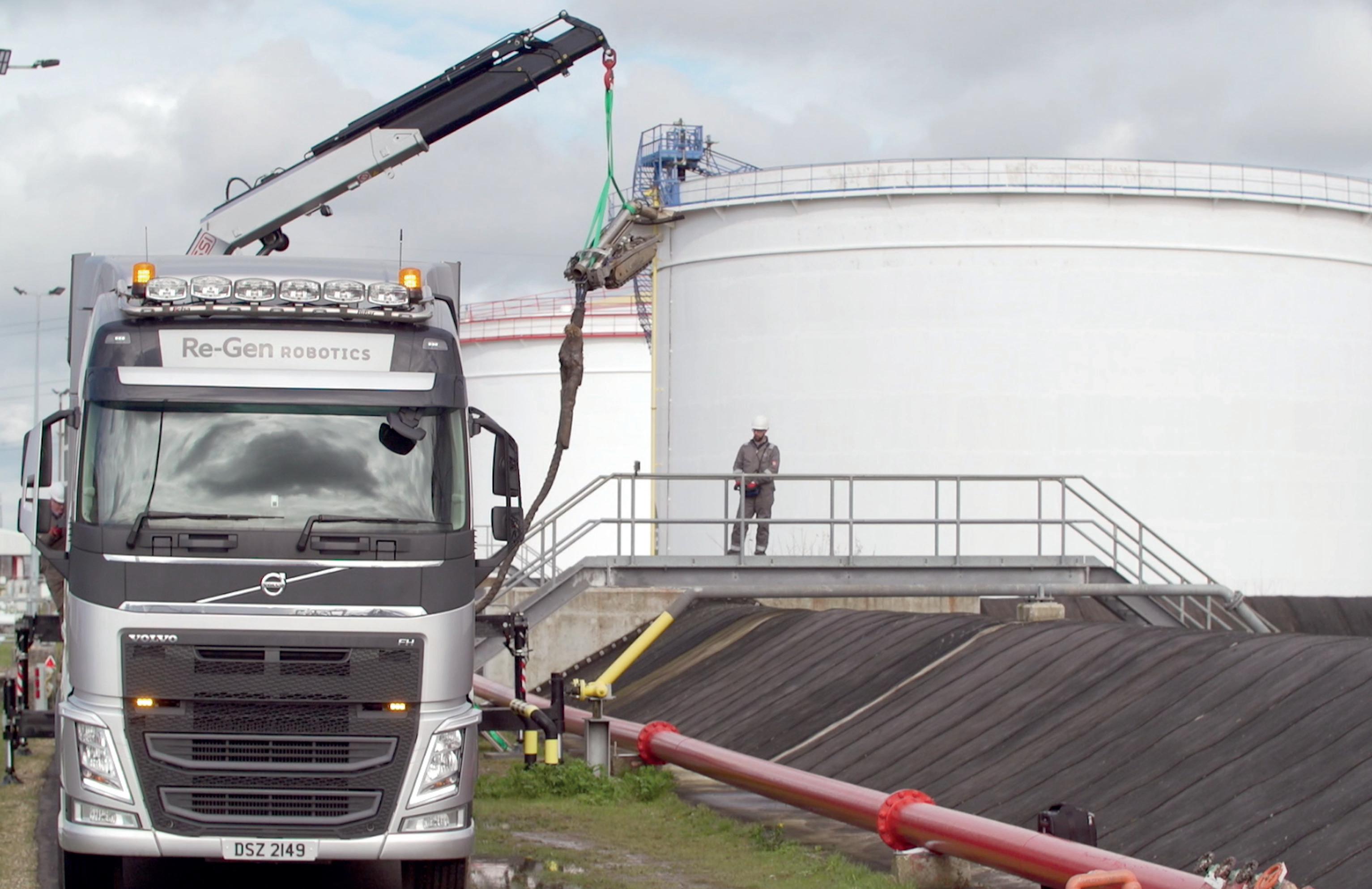
n Custom-designed external and internal adjustable hydraulic ramps, and ancillary equipment for its robots.
n The transportation costs are less as the system is fully contained.
n Cranes are designed to lift the robot over bunds and into position, therefore removing the need for scaffolding construction.
n No-man entry robots eliminate the need to spade the tanks.
n The robot is submersible and can work below the level of the sludge.
n The robot does not need to rest.
n The robot can operate in any temperature.
n No permanent changes are made to the tank.
n The most difficult parts inside the tank can be cleaned.
n Clients receive CCTV recording and intelligent performance reporting produced by telemetry equipment.
n Robotic cleaning meets all of the safety requirements in line with current regulations.
n All equipment is hydraulically driven.
n There are no electrical components inside the tank – LED lighting and surveillance cameras.
n The robot is installed up to 100 m away from the tank.
n The control unit is insulated and airconditioned, protecting staff from low and high temperatures.
n The closed loop circuit removes the sludge, and the waste deposited is negligible.
In the field of tank cleaning, the focus is on investing in methods that clean in a short time, with no-man entry robotic systems that do not require personnel to enter the interior of the tank and with the ability to recover hydrocarbons from the sludge, hence lowering the cleaning cost.
Robotic tank cleaning systems offer benefits including safety, performance, environmental protection, and cost savings.
Craig Senych, Eddyfi Technologies, Canada, outlines how the integration of robotic inspection crawlers in the tanks and terminals industry offers advantages in safety, efficiency, and cost-effectiveness.

The concept of using robots for inspection and maintenance of storage tanks and terminals is certainly not new. Innovative robotic technology plays a crucial role in replacing traditional and inefficient methods for cleaning, maintenance, and tooling applications. These outdated methods often involve manual labour, which can be time-consuming, labour-intensive, and prone to human error. By introducing robotic platforms, these tasks can be automated and streamlined, resulting in improved operational efficiency.
Yet in today’s rapidly evolving landscape of robotics, the term ‘robot’ has become increasingly diluted, encompassing a wide range of automated systems. Therefore, it is crucial
to distinguish the specific capabilities and characteristics required for industrial operations, especially when it comes to the inspection crawlers designed to withstand hazardous environments, overcome restricted access areas, and travel long distances often encountered in large storage tanks and terminals.
How are standard off-the-shelf inspection crawlers helping to address the various needs of tank owners and operators? These robotic platforms are equipped with advanced capabilities that enable them to perform a wide range of tasks with precision and accuracy. They can navigate complex environments, access hard-to-reach areas, and carry out intricate operations that would otherwise be
challenging or impossible for humans to accomplish. This level of automation reduces the time required for completing tasks, minimises the need for direct human intervention, and allows for increased productivity.
Tank integrity assessments performed by robotic crawlers is the perfect example of overcoming industry challenges. They work continuously in confined spaces, hazardous areas, and underwater environments where direct human intervention is too dangerous. The reliability and ease of use of these inspection crawlers ensure maximised productivity, improved overall quality, reduced risks, and lowered costs compared to traditional methods.
Shell has deployed Eddyfi Technologies’ robotic solutions for unmanned tank inspection to help ensure the integrity assessment of 11 000 underground storage tanks while prioritising personnel safety1. The use of inspection crawlers reduces health, safety, and environmental risks, saves time and travel costs, and enables better decision-making based on accurate recordings. Shell has observed significant cost savings and improved its safety culture by implementing these rugged robots. The future of inspection technology in the industry lies in integrating robotics with unmanned entry methods, eliminating the need for direct human intervention, and enhancing overall efficiency.
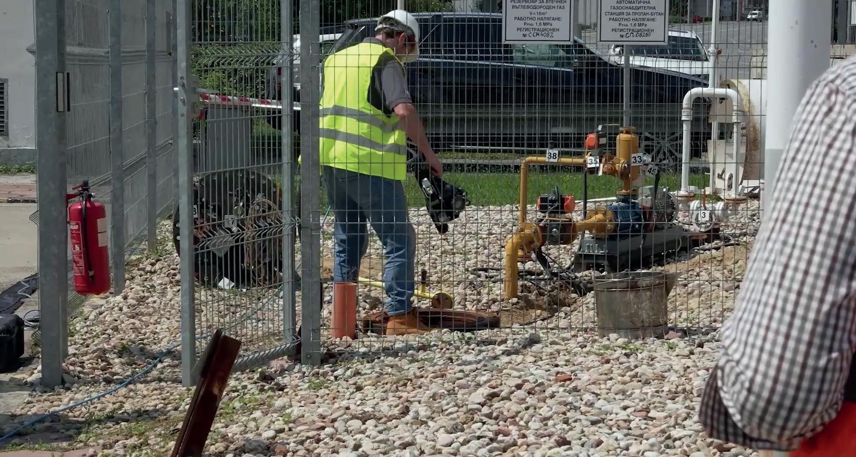
While inspection crawler robotic platforms primarily serve as carriers for non-destructive testing sensors, they can also transport maintenance and repair tools that need to be delivered to remote locations that are difficult for humans to access. This capability is particularly valuable in industries where infrastructure is spread over large areas or where hazardous conditions pose risks to human workers. By deploying robotic platforms to perform these tasks, asset owners can enhance safety by minimising human exposure to dangerous environments.
Robotic solutions can also be optimised to ensure efficiency and effectiveness where it matters the most.

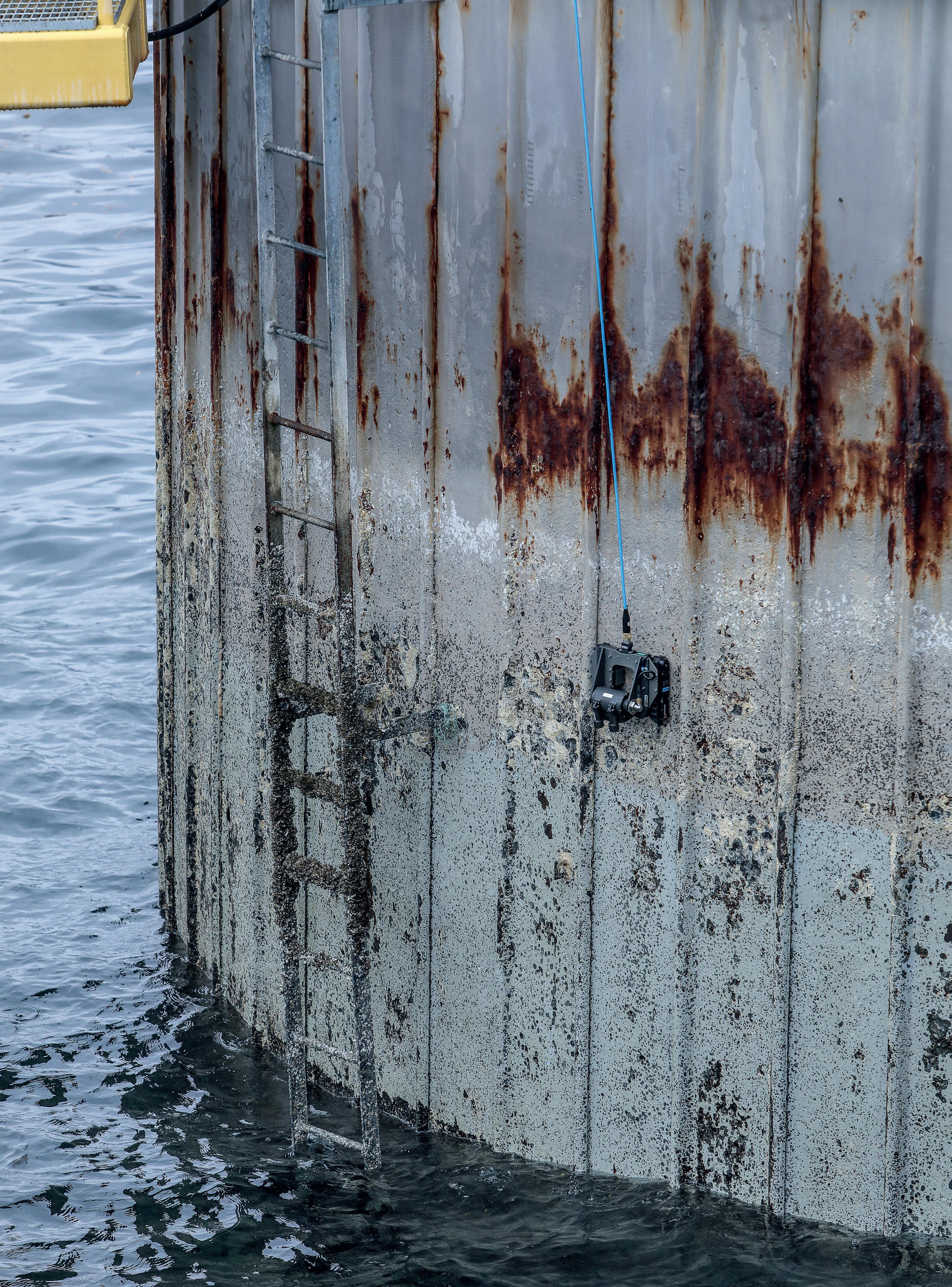
A multi-mission modular design approach to robotic systems offers customisable and adaptable solutions for a wide range of remote tooling requirements. By utilising proven engineering principles and design techniques, this methodology saves time, reduces costs, and mitigates risks associated with compatibility issues or having to start from scratch. The end result is the delivery of robust and compliant robots capable of performing various remote operations beyond inspection.
The benefits of these adaptable robots for remote tank operations are significant. As industries evolve and adjust to changing demands and technological advancements, a flexible workforce becomes crucial. With a priority on performance, reliability, efficiency, quality, and cost-effectiveness, these robotic platforms can be readily reprogrammed and reconfigured to accommodate new tasks and requirements, eliminating the need for major infrastructure or workflow changes. This flexibility ensures efficient and effective operations in the face of evolving industry standards and customer demands. Versatile inspection crawlers bring further advantages, reducing CAPEX, minimising downtime, and decreasing exposure to hazardous environments and associated risks. Customer-centric adaptable designs provide increased value and efficiency through expanded capabilities.
Figure 1. Non-intrusive inspection of tank exterior with inspection crawler. Figure 2. Forecourt fuel cell inspection.Custom robotic solutions offer versatility that has been applied to common applications across various sectors, including oil and gas, nuclear power generation, petrochemical, mining and heavy industry, public infrastructure and utilities, construction, and more. The mutual goal across these industries is improved safety, asset lifetime extension, cost-effectiveness, and reduced downtime, all of which can be achieved through the implementation of purpose-built robotic solutions. With applications ranging from tank inspection to fabric maintenance, asset remediation, foreign object search and retrieval, adaptable robotic technology opens the door to addressing a wide range of remote challenges.

The industrial needs for tank cleaning are represented within fabric maintenance as another critical area that robots are routinely deployed for remote asset maintenance in the chemical and energy sectors. Systems equipped with paint sprayers and multi-function arms ensure even application of paint in challenging environments found on offshore oil platform risers and other demanding locations.
Biofouling on offshore structures is a common challenge that can be effectively addressed with adaptable robotic technology. By integrating various cleaning mechanisms such as heavy-duty brushes and cavijet sprayers, these robotic platforms can remove marine growth and unwanted coatings from both offshore and land-based assets, maximising crew autonomy and optimising time and budget. Robotic solutions have been utilised for varying remote operations including recovery for many years. They can retrieve dropped tools, respond to natural disasters, and address counterterrorism needs. These custom crawlers and robots navigate constraints to recover objects that would otherwise cause problems or damage.
For industrial operations, the integration of inspection crawlers offers significant advantages in safety, efficiency, and cost-effectiveness. Specifically, tank inspection and tooling applications benefit from custom robotic solutions. These robots overcome challenges in hazardous environments, restricted access areas, and long-distance travel. Modular systems can be adapted to meet specific requirements, resulting in time and cost savings, improved productivity, and reduced risks. The future outlook for the industry is promising. Robotics continue to revolutionise remote operations, opening up new possibilities. As technology advances and industry requirements evolve, robotic solutions will remain at the forefront, delivering innovative and tailored solutions to meet the growing demands of industries all around the world.
1. https://blog.eddyfi.com/en/interview-series-brett-hovland-onwhy-shell-chooses-eddyfi-robotics.
Ideally arranged, the proper amount of Jet Mixers produces a three-dimensional flow that mixes the entire contents without creating a rotating motion in the tank. Delivering high efficiency, operational safety, resistance to fouling and little wear & tear thanks to its simple and robust construction Download
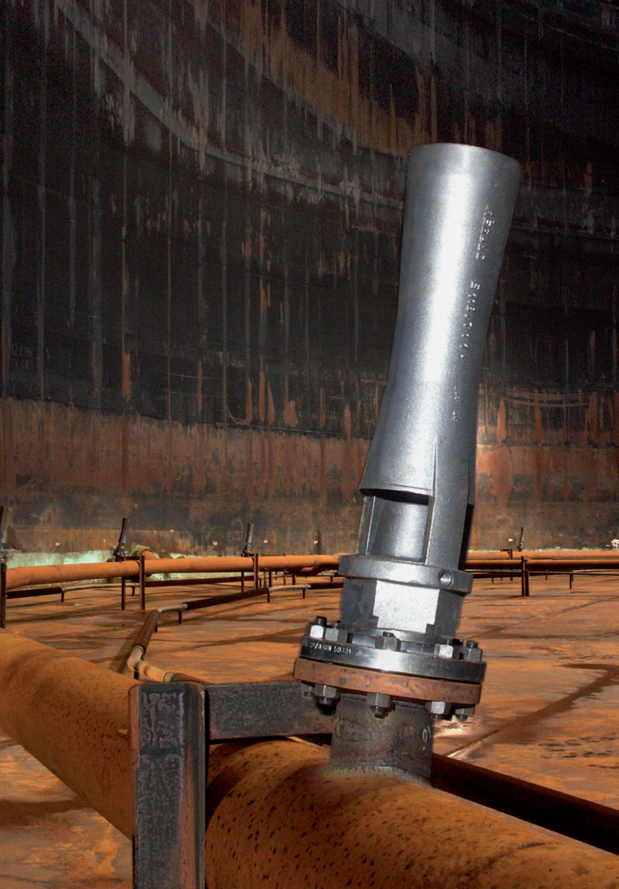


Currently, the bulk liquid storage industry is facing numerous challenges related to the environmental management of tank terminals. Environmental sustainability is the only viable path for the future of the tank storage industry. The implementation of technologies that combine the maximum efficiency in the elimination of gas venting emissions as well as in the recovery of vapours, with the highest energy efficiency in implementation and operation, will be of high importance. The goal of all these environmental solutions is to keep tank terminals operations running smoothly and safely, to avoid damaging productivity, and to protect people and the environment.
It is vital to reduce polluting emissions in all sectors. This becomes key at tank terminals, where there are significant hydrocarbon emissions, especially from venting during filling and emptying tanks, breathing, cleaning, draining, purging, connecting and disconnecting, etc.
The tank storage industry faces its greatest air emission problems whilst product is stored in tank farms. Changes in ambient temperature and pressure cause expansion and compression within the tank, resulting in the emission of polluting gases. They are called respiratory emissions – gases that become fugitive emissions.
Storage tanks also emit pollutants during loading and unloading of the product, transportation (loss through valves, ventilation holes, pumps to move the product), cleaning of the tank itself, and the mandatory prior inertisation for repair or dismantling of the tanks.
Regardless of the content, the characteristics of the warehouse (colour, fixed roof, floating roof, etc.) or the type of loss that occurs (permanent losses [breathing/standing losses], working loss), solutions that are personalised in each situation and in each project are required.
Technology that combines maximum environmental efficiency and resource optimisation to ensure maximum productivity is needed. It is necessary to eliminate polluting emissions from storage (tank breathing), loading and unloading of products, transportation, cleaning and inerting of tanks.
The following substances must be treated and removed: volatile organic compounds (VOC), carbon monoxide (CO), sulfur oxides (SOx), nitrogen oxides (NOx), particulate matter 10 micrometers (PM10), hydrochloric acid (HCL), petroleum hydrocarbons, gasoline, diesel, chlorinated hydrocarbons, oxygen-free waste gases, humid and corrosive waste gases, odours, halogenated particles and aerosols, hydrocarbons and CO, dioxins and furans, particulate matter and alkaline compounds.
Recently, the evaporation of hydrocarbons and their products in aboveground storage tanks has been a particular concern. Emissions from storage tanks are responsible not only for product supply depletion, but also for contributions to atmospheric air pollution.
Hydrocarbon storage tanks are a major source of evaporation of VOCs and non-organic gases such as CO and hydrogen sulfide, etc.
The operations of filling and emptying tanks cause emissions whose origin is in the variation of the level of the liquid and the expansion of the vapours.
Changes in ambient temperature and pressure can cause expansion and compression inside the tank, which causes the expulsion of polluting vapours. These are called respiratory losses – vapours that become fugitive emissions. In fixed-roof tanks, the more that empties, the more polluting vapours and emissions there are. On floating roof tanks, vapours can seep through edge seals, fittings and deck seams, etc.
During transportation, leakage may occur in equipment such as open and closed surface pipelines or underground pipelines, valves and accessories, loading arms for connection to boats, pumps to move the product through ducts and ventilation holes, etc.
During cleaning, vapours are generated by forced ventilation, at which point the emissions exit the tank.
During the previous and obligatory process of repairing or lowering the tanks, blanketing and emissions leaks can occur.
Especially at tank terminals, it is essential to have a correct, safe exhaust air management system to eliminate the VOC emissions generated during gas venting. These emissions happen during daily operations at tank terminals and require specific treatment, such as with regenerative thermal oxidation (RTO) technology.
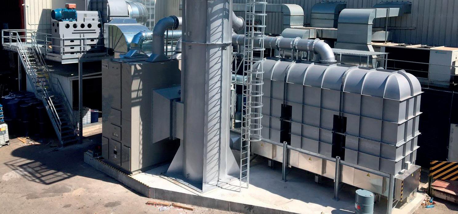
RTO systems usually work with burners that use gas or fuel to heat up the oxidation chamber during start-up so that oxidation of VOCs can take place. In the case of the electrically-heated RTO, there is no burner and therefore no flame and no NO x emissions generated. The oxidation chamber is heated up via some electrical resistances placed inside the oxidation chamber.
During start-up, the electric resistances will work at 100% to be able to heat the RTO oxidation chamber up to 1100˚C.
During operation, the consumption of electricity will depend on the VOC concentration at the inlet and its calorific value. If the concentration is above the autothermal point, resistances will turn off. Otherwise, if the concentration is lower than this point, the thyristors will modulate the resistances power to maintain the oxidation chamber temperature at 1100˚C to guarantee the oxidation of VOCs.
Vapour recovery units (VRUs) collect vapours from storage and loading facilities, liquefy them again, and return them as liquid hydrocarbons to storage tanks.
Methods to recover vapours include absorption, condensation, adsorption, and simple cooling.
VRUs can be combined with the RTO solution, an effective answer with significant cost savings. The integration of VRU and RTO equipment achieves the recovery of the product (through adsorption, absorption, separation by
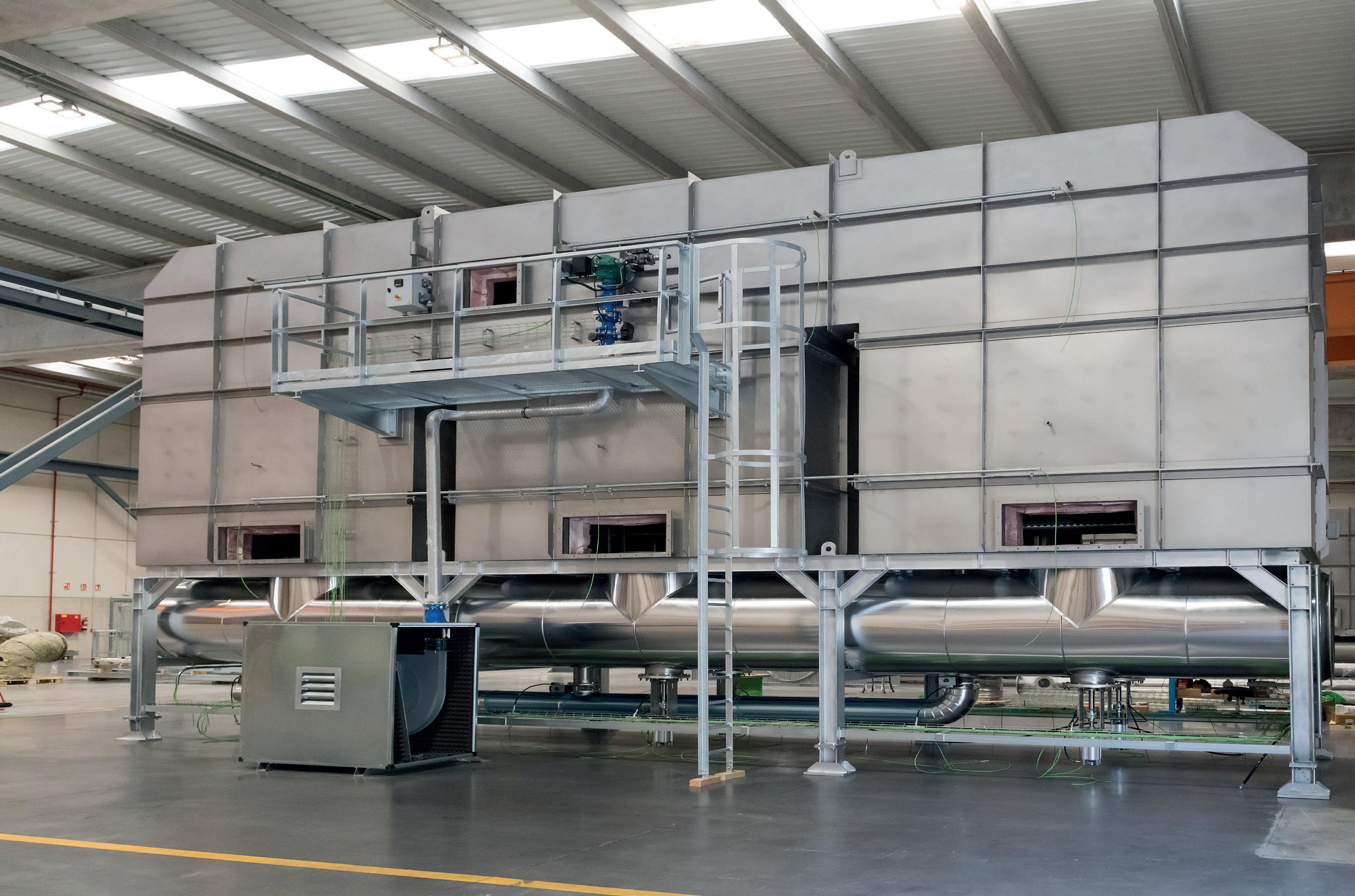 Figure 1. RTO equipment being assembled.
membranes and condensation) and the elimination of polluting emissions in a single installation that works in a coordinated manner, making it simpler and more efficient.

Gasoline contains VOCs that evaporate easily. Evaporated vapours, in addition to their effects on human health, are also harmful to the environment.
Thanks to VRUs, petrochemical plants and tank storage terminals will be able to collect vapours from hydrocarbon storage and loading facilities, re-liquefy that fuel and return it in the form of liquid hydrocarbons to storage tanks, thus recovering product, as well as taking care of the environment and people’s health and safety. The advantages of VRUs are as follows:
n Increasing safety and mitigating health risk.
n Recovering valuable resources (hydrocarbons, fuel, gasoline) for further use.
n Eliminating emissions of hazardous substances into the atmosphere and the environment.

RTO technology can provide an even more attractive performance for the tank storage sector if it is combined with VRU, as this technology allows for significant loads of hydrocarbons to be recovered from vents and used for processes, or stored. This means significant savings and efficiency from a production and operation perspective.
The combination of both RTO and VRU results in an optimised strategy to achieve the highest standards in
terms of cost savings, performance efficiency and adequate environmental management practices, and all under extremely safe conditions.
RTO is currently the most suitable technology for gas venting emissions abatement, and is one of the solutions recommended for that goal by the European Commission in its reference document on best available techniques on emissions from storage. RTO should be used together with technologies such as adsorption, absorption, condensation and membrane separation.

The tank storage industry faces several environmental challenges. The main challenge that the sector must tackle is the treatment of venting gas emissions, in order to preserve the health and safety of people and facilities, as well as to protect the environment. This can only be achieved with the most efficient solutions, and a reliable technology partner.
Companies in all industrial sectors – above all tank terminals – have to ensure that they carry out and guarantee good practices. As far as emissions treatment is concerned, exceptions and excuses cannot be accepted in today’s demanding world. We all need to be part of the circular economy and participate in environmental protection actions, for a cleaner and safer tank storage sector.
We can tailor to your requirements, produce 1 - 12 page formats, print colour or mono and more
provides a case study of a bottom loading overfill incident and explains what can be learnt from the experience.
Overfills when loading fuel into bottom loading tank vehicles happen more often than we hear of. Fortunately, there are good technical solutions and organisational procedures to protect loading terminals from dangerous overfill situations if applied correctly. The following case study details an overfilling incident, giving practical advice on how dangerous situations can be prevented. The incident occurred in 2023 at a European fuel terminal.

Almost without exception, petrol/gasoline is loaded through the bottom valves into tank vehicles in industrialised nations. This often also applies to diesel/fuel, heating oil and JET, although top loading is still allowed for these products. The advantages of bottom loading are as follows:
n Simpler loading facilities.
n Safer working environment.
n Simultaneous loading into multiple tank compartments.
n No environmental impact due to vapour collection and recovery.
US and European standards of applied technology are used or serve as the basis for national rules: US API RP 1004 describes the functional and technical design of bottom loading terminals and vehicle equipment; the European standard EN13922 defines the electrical specifications of the overfill prevention system. These standards aim to ensure interoperability between terminals and tank vehicle fleets from different operators, companies or countries.
The loading equipment at terminal loading bays or islands is typically skid-mounted. These skids contain the fluid transfer, metering and blending equipment, a mechanical quantity preset or a loading computer, the overfill prevention controller, an emergency stop, and associated control equipment. Multiple loading hoses/arms with API couplers and a vapour recovery hose/arm are connected to the skid.
Tank vehicles are equipped to fit with the terminal equipment. They provide API adapters for each tank compartment, a joint vapour recovery connector, overfill prevention sensors at the top of each tank compartment, and the socket for connection of overfill prevention and grounding. The overfill prevention sensors are wired to this standard socket and monitored by the overfill prevention controller during loading. If the liquid level inside the tank compartment touches the overfill sensor, which indicates that the compartment is filled above the allowed level, the overfill prevention controller will trigger an immediate stop of further fluid transfer into the tank
vehicle. Subsequent flow shutdown takes place within 2 – 4 seconds via independent secondary shut-off valve.
The overfill prevention controller at the loading skid is the central safety device. It only permits loading if the overfill sensors are functioning properly and have no contact with the liquid, electrostatic grounding is detected, and vapour recovery is connected. In the event of an unsafe situation, the loading process will not be permitted. The controller has a status light (green/red) to provide clear indication to the operator, and is wired through its dry contacts (relay outputs) to the loading control system.
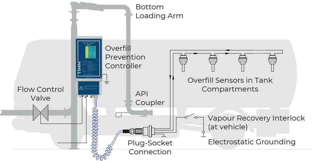
The incident described took place in Central Europe at a fuel storage terminal. A bottom loading tank vehicle entered the terminal and drove to the assigned loading bay. The multi-chamber vehicle was supposed to load 32 000 l of fuel. The driver positioned the vehicle and connected the overfill prevention cable to the standard socket on the vehicle. However, the overfill prevention controller refused to issue loading permissive. This was most likely because of a defective overfill sensor. However, instead of leaving the terminal and having the vehicle repaired, the driver decided to violate the applicable rules: a self-made adapter was taken from their driver’s cab and connected to the overfill prevention cable. This adapter imitated correct sensor signals and deceived the overfill prevention system. The driver set the desired loading quantity for each compartment at the preset and started the loading.
At this point, the first dangerous situation arose. Since the overfill prevention connection to the vehicle was not established, electrostatic charges could no longer be dissipated safely. With each passing second of loading, the vehicle was charged with static electricity, posing an immediate risk of explosion due to electrostatic discharge.
During the loading process, fuel suddenly spilled out of one of the compartments. Gasoline fuel being pumped into an overfilled tank compartment at a rate of 2300 l/min was spilling at the same rate onto the loading bay floor. A highly explosive atmosphere formed immediately above the spilled liquid (gasoline has a flash point of -25°C). At any moment, the electrostatically charged tank vehicle could have caused a spark discharge.
With a lot of luck, the tanker driver was able to interrupt the fluid transfer after a short reaction time. The driver disconnected the overfill prevention cable from the adapter and connected it to the socket on the truck. By doing so, the fluid transfer stopped. The driver promptly hid the adapter and informed the supervisor that an overfill incident had occurred. As is standard in fuel terminals, a post-incident procedure was initiated, and an investigation into the circumstances was launched.
The driver’s wrongdoing only came to light during a subsequent detailed examination of video recordings and

through insistent questioning. However, by this time, the driver had already left the site. The illegal adapter could not be secured. The overfilling and spillage happened because the driver mistakenly confused the capacities of the tank compartments while setting the loading quantities.
The causes for overfilling can be attributed to the actions of individuals as well technical equipment. The case explored in this article is particularly unique. Generally, minor carelessness, undetected defects, or a combination of circumstances lead to overfill situations. Fortunately, the vast majority of overfills are reliably prevented by the overfill prevention controller before a hazard arises.
Bottom loading is a highly safe loading technique. Nonetheless it is essential to address the various dangers and raise awareness about them. The following measures can help reduce the probability of overfill incidents:
Overfill prevention and electrostatic grounding are crucial and must be in place. These systems can be separated, particularly in the case of top loading of fuels. In such applications, an overfill sensor is attached at a designated height at the top loading cone, which is inserted into the vehicle dome opening together with the drop pipe. Electrostatic grounding is realised by using a grounding control device via grounding clamp and cable. The operator attaches the grounding clamp to the grounding point of the vehicle. The grounding control device must have a truck detection function since, unlike bottom loading, a standard plug and socket connection does not establish the grounding.
For fuel bottom loading, an additional grounding control device is usually not necessary. The overfill prevention controller can establish and monitor the electrostatic grounding, as stated in the European VOC-Directive 94/63/EC, for instance. An appropriate overfill controller for fuel bottom loading should include the following functions:
n Electrostatic grounding as an integral function and permissive criterion.
n Indication of the overfilled tank compartment number.
n A readable text display for operators and supervisors to simplify error/fault diagnosis.
n Configurable control signals for grounding, overfill alarm, or plug stored, enabling a sophisticated process control.
n Intelligent explosion protection with continuous monitoring of all safety-related device functions.
Any bypassing of existing safety technology must be avoided. However, it is possible to override the safety functions of some overfill prevention controllers with a bypass key. A bypass function is always problematic
because if it exists, it will most likely be used, either by a persuaded supervisor, a deputy using the bypass key on their own authority, or during night shift.
Thus, the obvious solution is to only use control devices that do not compromise saftey. It is strongly recommended that only equipment that actually delivers what it is supposed to provide is used: reliable overfill prevention and electrostatic grounding without the possibility of bypassing these essential safety functions.
As demonstrated in this incident, technical aspects are only one side of the coin. Intentional, almost criminal behaviour or carelessness regarding safety practices can lead to hazardous situations. To counteract this, soft factors should be taken into account and procedural regulations be implemented. Here are some examples:
n Testing equipment, sensor dummies or other elements that could be used for safety bridging purposes must be kept under lock and key, and drivers should not be allowed to take them to the terminals.
n Educate about dangers, including tanker drivers and transport companies, to establish a common understanding of safety.
n Conduct operator and driver training regularly with explicit consideration of correct usage of overfill prevention and electrostatic grounding equipment.
n Implement sanctions, such as terminal bans, for individuals who disregard safety regulations. For truck drivers, for instance, this should be a joint understanding with the freight forwarders who employ them.
Terminal operators must ensure that the established rules are followed at their facilities. Various monitoring options can uncover misconduct and manipulation:
n Plausibility check between the number of tank compartments displayed at the overfill prevention controller, and the visible vehicle compartments. A modern overfill prevention controller can transmit the number of detected compartments to a host computer system, allowing for automatic matching with a database (truck data submitted by a terminal management system).
n Video surveillance with simulations in the presence of technical data coming from a loading control system, so that the supervisors can compare what they see with what is going on according to the instruments.
n Random inspection of tankers to check for irregularities in the technical installation.
Bottom loading is a highly safe, economically-efficient and environmentally-friendly technique. The suggestions provided in this article aim to prevent potential hazards and ensure that flammable liquids are safely handled at all times.
As companies strive to reduce the carbon footprint of their operations and optimise energy efficiency, properly insulating industrial assets can help businesses achieve both goals. Storage tanks operating at above ambient temperatures typically hold a variety of liquids that require insulation capable of maintaining thermal conditions. Getting the insulating system right at the base of the asset – literally at the tank base – can help conserve energy usage, protect both the

Jente Quintens, Owens Corning, explains why storage tank owners should adopt the practice of insulating tank bases and the criteria that should be considered when designing insulation systems for such purposes.
quality of stored contents and the storage tank itself, and support worker safety on the jobsite.
Typically placed at the top of a concrete substrate, the hot tank base is a location where an appropriate insulating strategy can help support optimal thermal performance. As concrete is not a particularly effective insulator, installing an insulating material between the concrete and the tanks’ base can help reduce thermal loss. In turn, as thermal loss declines, a related drop in CO2 emissions may contribute to improved performance. Throughout its service life, properly installed insulation can also help safeguard the tank. As hot tanks store hazardous chemicals and solutions, the contents can damage the tank base, leak through the concrete and pose a safety and environmental concern.
This article makes a case for why storage tank owners should adopt the practice of insulating the tank base. This area is often overlooked when it comes to insulating industrial infrastructure. It will also present a scorecard of criteria for assessing an insulating material’s ability to deliver different properties to meet the needs of hot tank base applications. Finally, this article examines a practical example of how a high-load bearing cellular glass insulation installed in storage tank bases in Europe’s busiest port is helping to ensure consistent thermal performance.
The conventional insulating practice for hot tanks in North America has been to insulate the roof and sides of a tank but leave the base uninsulated. This approach does not consider that the base is the one part of the tank that is constantly exposed to the weight and chemistry of stored contents. Unless the tank is filled to capacity, the bottom of the storage tank presents a major source of energy loss. While hot liquids may not be in constant contact with tank walls as storage levels fluctuate, hot tank bases are exposed to constant contact with hot liquids stored inside. As such, the base represents an area where the threat of heat transfer and energy loss is sustained. Additionally, liquid stored in a hot tank can lose its viscosity and solidify, thus damaging its contents.
Insulation can play an important role in defending against such risks and safeguarding thermal appearance. However, insulating materials vary widely in their thermal performance and it is important to consider how material science and the composition of an insulating material informs its mode of action. Selecting a closed-cell insulation that does not permit moisture to infiltrate into the material is essential. Used in hot tank base applications, cellular glass (high-load bearing FOAMGLAS®) insulation acts to help prevent moisture from rising up from the soil. This keeps the liquid moisture from passing through the concrete where it can come into contact with the steel tank bottom and allow corrosion to occur. Beyond damaging the asset, corrosion also can diminish thermal performance. For this reason, an insulating material should be impermeable to moisture.
As the environmental attributes of different insulating materials are considered, a material’s composition should be assessed. In today’s business climate, companies are seeking not only to reduce thermal heat loss, but also carbon emissions. Cellular glass insulation can help to support reduced carbon emissions as it conserves thermal energy. Unlike insulating materials that deliver reduced thermal performance over time, cellular glass insulation provides constant thermal performance over the lifetime of the tank.
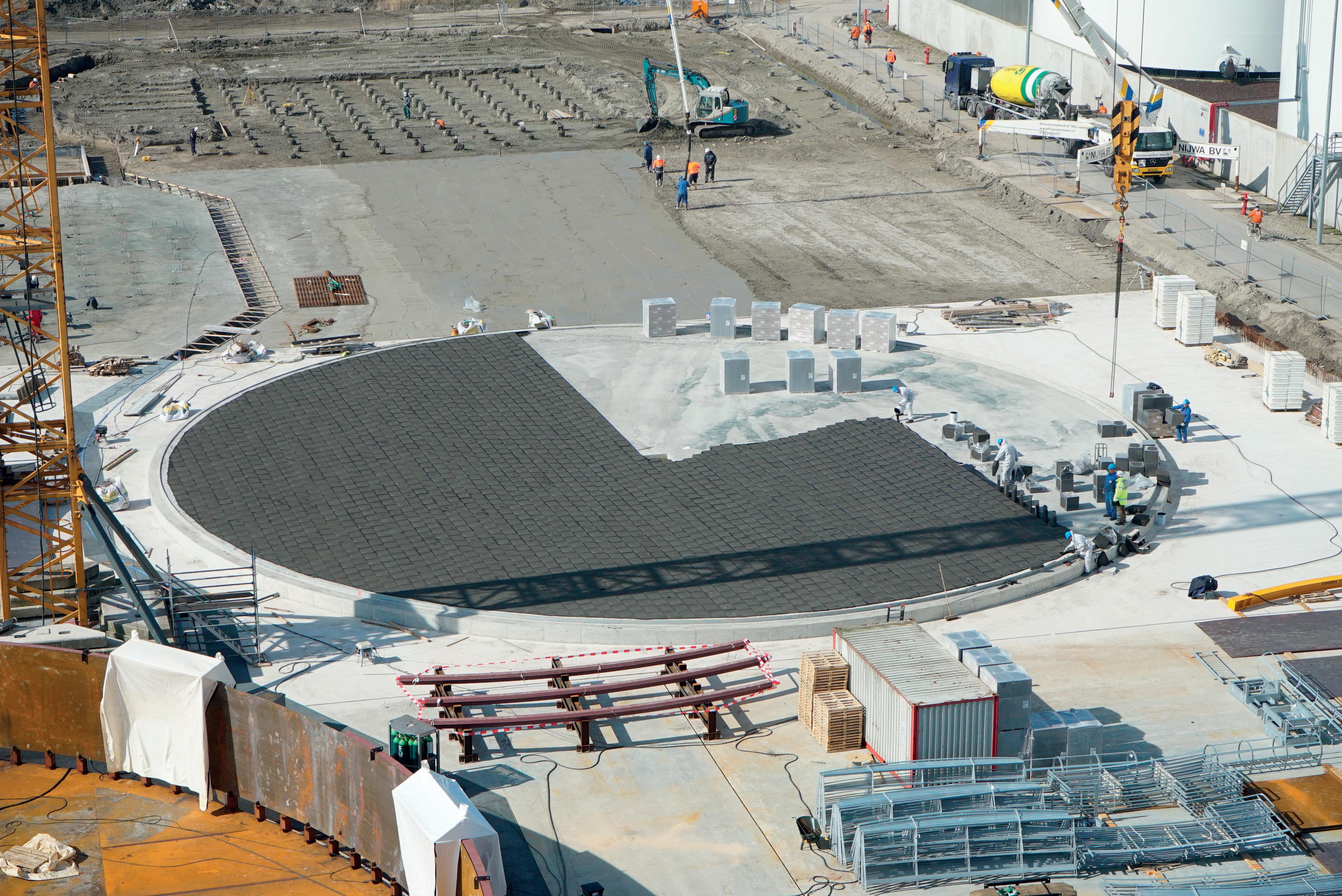
Several other factors should also be considered. The scorecard below lists seven additional criteria that should be considered when designing an insulating system for hot tank bases.
The weight of storage tanks, as well as the contents that they house, present an immense weight load on the base. As such, any insulating material must be able to withstand the compressive load. An insulating system without sufficient strength can lead to failure, potentially allowing hazardous tank contents to escape and pose a safety risk.
The performance behind cellular glass is influenced by its compressive strength and related to the geometry of its cell size. When it comes to industrial tanks, FOAMGLAS high-load bearing (HLB) cellular glass insulation can withstand up to 2400 kPa/340 psi. Third-party compression testing has shown that blocks available in high load bearing grades specially designed for tank base applications can deliver a compressive strength up to 160 t/m2 without any compression.
Many hot storage tanks hold contents that require a constant temperature to maintain the properties they deliver in various applications. Asphalt, bitumen and sulfur are just some products used in industrial applications that can degrade if the proper temperature is not maintained. Solidification and increased viscosity are just a few quality issues that can affect stored contents. Similar problems can

happen with some oils. For example, certain biofuel storage providers (stored at 65˚C to 75˚C) are choosing to insulate tank bases to save on energy costs. Beyond the cost of lost energy, reduced quality of contents may mean price reductions in the marketplace. With this in mind, thermal performance also plays a role in protecting product quality.
Cyclical tanks are not classified as tanks that store a particular product and such tanks may store different contents across their service life. For example, a tank that holds fuel today may be used to store feedstock in five years under ambient conditions. Insulating the bottom of the tank can allow it to be used for hot as well as ambient storage. Higher energy prices have led to some situations where it is economical to lift an existing tank and install a new base. While the return on investment is longer, this can be a cost-effective option.
An insulation system for tank bases should last the life of the asset. The normal service life of a tank is 15 - 20 years. With such a long service life, it can be expected that the insulation will outlive the life of the asset. As economics are always a consideration, the payback period for insulating the bottom of a storage tank bottom can be as short as just a few months and often within a few years. Installed as a core component of more than 90% of the world’s LNG tank base insulation systems, FOAMGLAS HLB insulation helps support and sustain long-term performance.
Hot tanks often store potent and combustible materials such as LNG and petroleum products. In addition, hazardous chemicals used in industrial applications can potentially corrode metals at the base of the tank. Selecting a non-combustible material helps support worker safety. Selecting a material that defends against degradation at the base can help protect against the risk of contents leaking into the external environment. Considering material properties, the closed-cell nature of cellular glass makes it impermeable to liquid or vapour moisture. As liquid cannot permeate the insulation, cellular glass insulation helps defend against corrosion damage at the tank base.
Lightweight rigid cellular glass blocks are easy to handle and install on the jobsite. However, start-up technical support on-site provides an added level of confidence that the material is installed according to specification.
Any investment to improve performance must be considered in context with the cost. Calculating the amount of insulation, load of the tank, energy costs and temperature can inform an expected return on investment for insulation. Installed in Europe, where energy prices have traditionally been high and sustainability has been prioritised, cellular glass insulation provides an impressive track record from an economic and performance
perspective. Every tank situation is different and calculations can help determine the payback period. Tank builders and terminal owners can rely on technical service teams to assist with the calculation of payback periods and annual yields of the investment in a FOAMGLAS HLB insulation tank base insulation system. The calculations consider relevant factors such as temperatures and local energy prices. For each project, the heat lost through the base without insulation is calculated and compared with the total investment cost, providing an expected payback period of the investment in a FOAMGLAS tank base insulation system. This period can be as short as merely months depending on the storage temperature of the contained liquid.
A major terminal operator located in the port of Rotterdam, the Netherlands, sought an insulating strategy for a 24/7 terminal with a storage capacity of 625 000 m3. In 2017, the terminal operator completed construction of new 30 m high oil storage tanks with an individual capacity of 30 000 m3. Each tank was insulated with FOAMGLAS HLB insulation. When selecting an insulation for the base, consistent thermal performance was an essential consideration and longevity was also an important criteria in the decision.
Managing a significant pressure load was a core challenge for the team designing the insulating system. The steel weight of 8 t/m3, combined with the weight of the tank roof and pressure place an immense load on the tank wall. As contents fill the tank, the total pressure on the FOAMGLAS tank base insulation system will increase up to 30 t/m2. With this load in mind, specifiers opted to install FOAMGLAS HLB 1600 insulation blocks. The product data sheet report indicates the insulation can withstand five times the amount of pressure placed on the tanks.
When it came time to plan the installation, the appropriate insulation thickness to achieve optimal efficiency was calculated. A single layer comprised of 100 mm FOAMGLAS HLB 1600 insulation blocks was installed at the base above the concrete slab.
When considering the economics of the investment, calculations performed by the engineering team assigned to the projects in Rotterdam indicated an average payback period of 12 to 18 months based on the contents stored, local energy prices and variables specific to the project. For specifiers considering the economics, as well as the strength of an insulating material, the compressive strength of FOAMGLAS HLB may even make it possible to reduce the amount of rebar required to support the tanks’ weight, reducing operational costs.
Energy efficiency and sustainability are in the spotlight. Supporting the hot tank base with an insulating material that can reduce the operational costs of a tank, and support safety as well as ease of use on the jobsite can help satisfy the economics and objectives of hot storage tank owners.
Corrosion prevention has been a longstanding challenge in the storage tank industry, as leaks and environmental hazards were once considered an inevitable cost of doing business. However, industry concerns and rising oil prices during the 1960s led to a shift in mindset, prompting the development of solutions to address tank leakage. Tank linings and cathodic protection systems emerged as effective measures to combat steel corrosion. While these methods brought significant improvements, protecting the tank bottom remained a persistent problem, especially during welding processes.
This article explores the historical evolution of corrosion prevention techniques and highlights the limitations associated with traditional methods. It then introduces a chemically bonded phosphate ceramic coating as a case study which presents a solution for protecting tank bottoms. By examining the coating’s properties, its compatibility with high
temperatures and ability to improve over time, this article examines its potential to increase corrosion prevention in the industry.

Between the 1970s and 1990s, a notable change in society’s attitude toward environmental hazards associated with leaking tanks occurred, triggering a revolution in the industry’s approach to corrosion prevention. Significant progress was made in developing effective tank linings and coatings that could protect tank exteriors and roofs. Cathodic protection systems gained prominence, particularly for tanks that could be electrically isolated using coatings or barriers. Despite these advancements, the challenge of protecting tank bottoms persisted. Traditional coatings were impractical for the soil-facing side of tank bottom plates due to the burning off of the coating during welding, which compromised the effectiveness of cathodic protection and exacerbated localised corrosion.
Recognising the need for a corrosion protection solution that would withstand the thermal shock of welding without degradation, EonCoat approached the problem from a thermodynamics perspective. The company looked for a way to enable the steel to protect itself by forming a multi-metal phosphate alloy layer. Its scientists conducted extensive research to identify a non-toxic mineral capable of withstanding high temperatures, ultimately selecting olivine due to its exceptional properties.
The chemically bonded phosphate ceramic coating is an inorganic material renowned for its ability to withstand high temperatures, including the intense heat generated during welding (up to 1700°F) for short periods. This sets it apart from traditional polymer-based coatings that often burn-off or degrade under similar conditions. To validate its effectiveness, the coating has undergone rigorous testing and validation by NASA and EWI, demonstrating exceptional corrosion protection capabilities over long periods of time.
The coating has the ability to provide uniform corrosion resistance across both bare steel surfaces and welded areas. This ensures comprehensive protection for the entire tank bottom structure, eliminating localised vulnerability. As the coating reacts with the metal over time, it forms a passivation layer comprising magnesium, iron, and phosphate. Notably, this passivation layer continues to strengthen and improve as the coating ages, offering long-term durability that surpasses the life expectancy of the tank asset itself.
The implementation of this chemically bonded phosphate ceramic coating offers several advantages and opens up a range of applications within the storage tank industry. Firstly, the coating’s ability to withstand the heat of welding without burning off ensures uninterrupted corrosion protection during tank construction and maintenance activities. This eliminates the need for post-weld touch-ups and reduces costs and downtime associated with reapplication of coatings.
Furthermore, the coating offers long-lasting protection. Unlike conventional coatings that may require periodic maintenance and reapplication, chemically bonded phosphate coatings are believed to provide permanent corrosion protection. The ongoing reaction between the coating and the metal promotes the formation of a robust passivation layer, which improves with time and enhances the coating’s durability. This longevity offers significant benefits, reducing maintenance needs and associated costs throughout the lifespan of the tank asset.
Environmental sustainability is another significant advantage offered by this solution. The coating is non-toxic, ensuring the safety of workers and preventing damage to the surrounding environment. By minimising the reliance on temporary plastic barriers and enabling steel to protect itself, the coating’s enironmental impact is reduced.
The successful implementation of chemically bonded phosphate ceramic coatings by notable industrial customers, including Honeywell and several oil and gas companies, demonstrates its effectiveness and reliability. The adoption of this innovation by industry leaders has paved the way for wider acceptance and showcases its potential to enhance corrosion prevention practices.
Recently, Charter Labs presented its findings from a study commissioned by one of the leading major oil and gas companies during AAMP 2023. It conducted both salt fog, immersion testing, ageing, open circuit and polarisation testing. Pull-off testing revealed an interesting finding – the bond gets better over time and with stress.
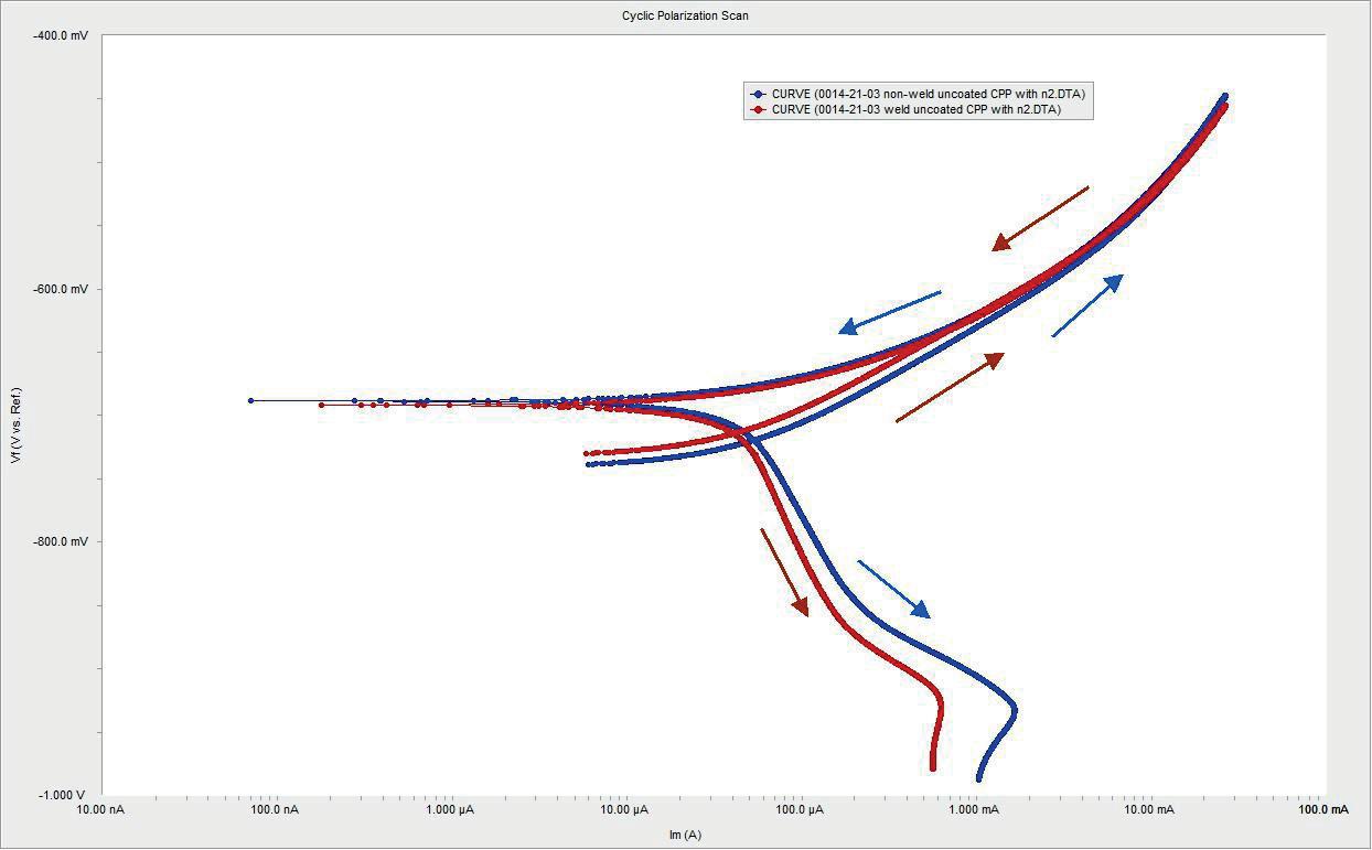
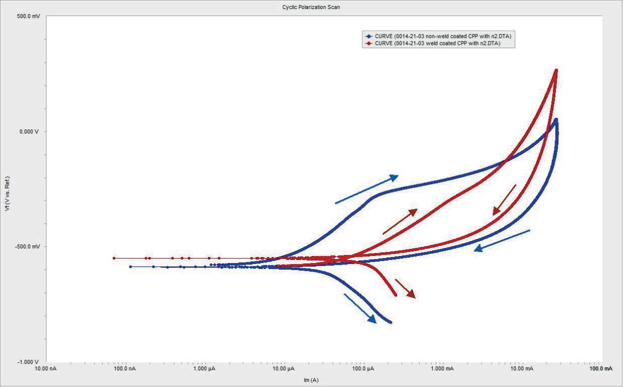 Figure 1. Welded and unwelded cyclic polarisation (measurement of corrosion rate) are nearly the same for welded and unwelded coated plates. Welded is slightly better.

Below is a summary of the key findings:
n Open circuit potential: the welded and coated sample showed a decrease in potential, indicating the presence of a passive layer for corrosion protection. The open circuit potential did not significantly differ between welded and non-welded samples.
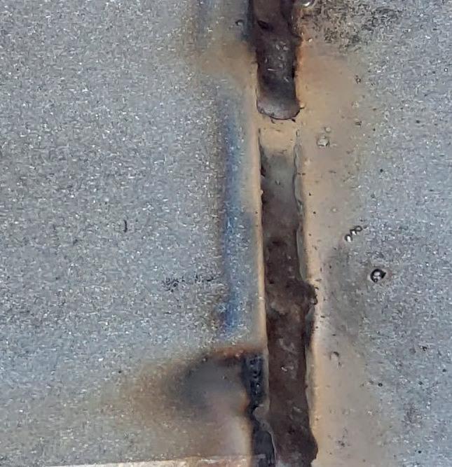
n Linear polarisation: initially, the welded and coated sample exhibited a lower polarisation potential, indicating a higher
corrosion rate compared to the non-welded and coated sample. However, after two weeks, both samples showed similar behaviour, suggesting that the ceramic layer provided the phosphate to restore protection.

n Cycling polarisation: the non-coated samples showed typical passivation behaviour with increasing pitting potential and subsequent repassivation. However, the welded and coated samples did not exhibit the same increase in pitting potential.
n Immersion testing: the welded and coated samples, as well as the non-welded and coated samples, showed no signs of blistering, cracking, swelling, rusting, or coating degradation after one to three months of testing.
n The pull-off adhesion strength increased over time for the welded and coated sample, with the mode of failure shifting from adhesion to steel to cohesive failure within the ceramic layer.
n Ageing resistance testing: the welded and coated samples, as well as the non-welded and coated samples, exhibited no blistering, colour change, or signs of degradation during the ageing cycles. The pull-off adhesion strength increased for the welded and coated sample, while the non-welded and coated sample remained relatively constant. Artificial scribes on the weld and non-weld samples showed similar performance after the third cycle.
These results suggest that the welded and coated samples, despite some initial differences, performed comparably to the non-welded and coated samples in terms of corrosion protection. The ceramic layer of the coating system played a crucial role in mitigating corrosion. The performance of the coating showed improved adhesion and resistance to degradation observed over time.

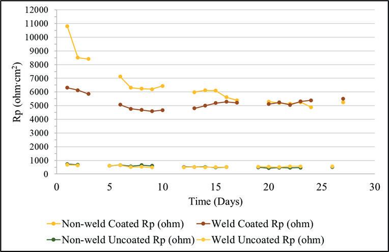
The storage tank industry has made remarkable progress in addressing corrosion and leakage challenges over the years. While tank linings, coatings, and cathodic protection systems have significantly improved corrosion prevention, protecting tank bottoms during welding operations has remained a persistent problem. Chemically bonded phosphate ceramic coatings present a solution to this challenge.
With its ability to withstand high temperatures, including welding heat, and its capacity to improve and strengthen corrosion protection over time, this coating offers promise. Its application ensures comprehensive and long-lasting protection for tank bottoms, surpassing the limitations of traditional methods.
As more industrial customers embrace this innovation and independent studies validate its effectiveness, chemically bonded phosphate ceramic coatings are poised to transform corrosion prevention in the storage tank industry. Most importantly, the technology can help to solve corrosion issues without exposing employees to toxins and putting them in confined spaces with flammable materials, and there will no longer be a need to atomise pollutants and spray them into our environment.
Figure 3. The electrical resistance (resistance to corrosion) of the coated panels is much greater than bare panels. More significantly, the resistance of both welded and unwelded coated panels is roughly equal after 15 days. Figure 4. A decrease in the open circuit potential (OCP) of the coated panels verifies the presence of the passivation layer.Every day, the liquid-storage industry provides billions of gallons of crucial raw materials and end products. From common to niche chemicals, the industry plays a pivotal role in providing valuable liquid commodities that the world depends on.
Regardless of the commodity, whether it be refined fuels, chemical-based, or food-based, every liquid must be transferred through storage tanks and terminals. The process involves ensuring that the liquid is quickly and safely transported throughout the entire supply chain, from ship, barge, railcar or tank truck into the terminal. This process is only made possible with an efficient and reliable pump as
every second in the operation is as valuable as the liquid being transferred.

Pump selection directly impacts the effectiveness of a terminal’s entire operation because time is a liquid-terminal’s most valuable resource. Profitability relies on transferring liquids as quickly and effectively as possible and a versatile and effective pump is key to that.
As mentioned, the purpose of the liquid-terminal industry is to turn over raw materials and end products safely and efficiently until the liquid commodity reaches its
Geoff VanLeeuwen, Blackmer, USA, explains how the liquid terminal industry can save time by ensuring that the right pump is selected.
final destination. Transferring and storing with streamlined pump technology and minimal human interaction can drastically improve the loading and unloading process, ensuring operational safety, compliance with federal regulations, and conservation of valuable time. However, there are a number of extremely challenging problems that can arise for pumps at any moment throughout the supply chain.
This article will detail a number of circumstances that can affect the effectiveness of pump selection, whether it be a centrifugal pump or a positive displacement pump, such as vane, screw, and gear. Poor pump selection can prove detrimental to a liquid-terminal operation, increasing transfer times, equipment downtime, and maintenance.
Liquid-terminals often have numerous tanks with complex interconnecting pipe networks. Each flow path has varying adjustments to the length, fittings and valves that can impact the flow rate (i.e. transfer times) of the pumps. Pumps that are optimised for a single operating point, such as centrifugal pumps, are unable to accommodate a wide array of pipe networks. When flow rate is dependent on backpressure (centrifugal pumps), operational issues like runout, cavitation, and dead head are common, causing leaks, material damage, and the overload of motor trips.
By design, liquid-terminals expect frequent changes to tank liquid levels. As liquid levels change, the system curve shifts accordingly. Most engineers specify a single operating point, typically at the maximum differential head or ‘worst case scenario.’ This is when the supply tank is at the lowest level and the destination tank is at its highest level. A centrifugal pump sized for this condition will runout when the supply tank level is higher or destination tank level is lower. This runout condition often causes cavitation, overloading of rotating components, and overload trips of the motor.
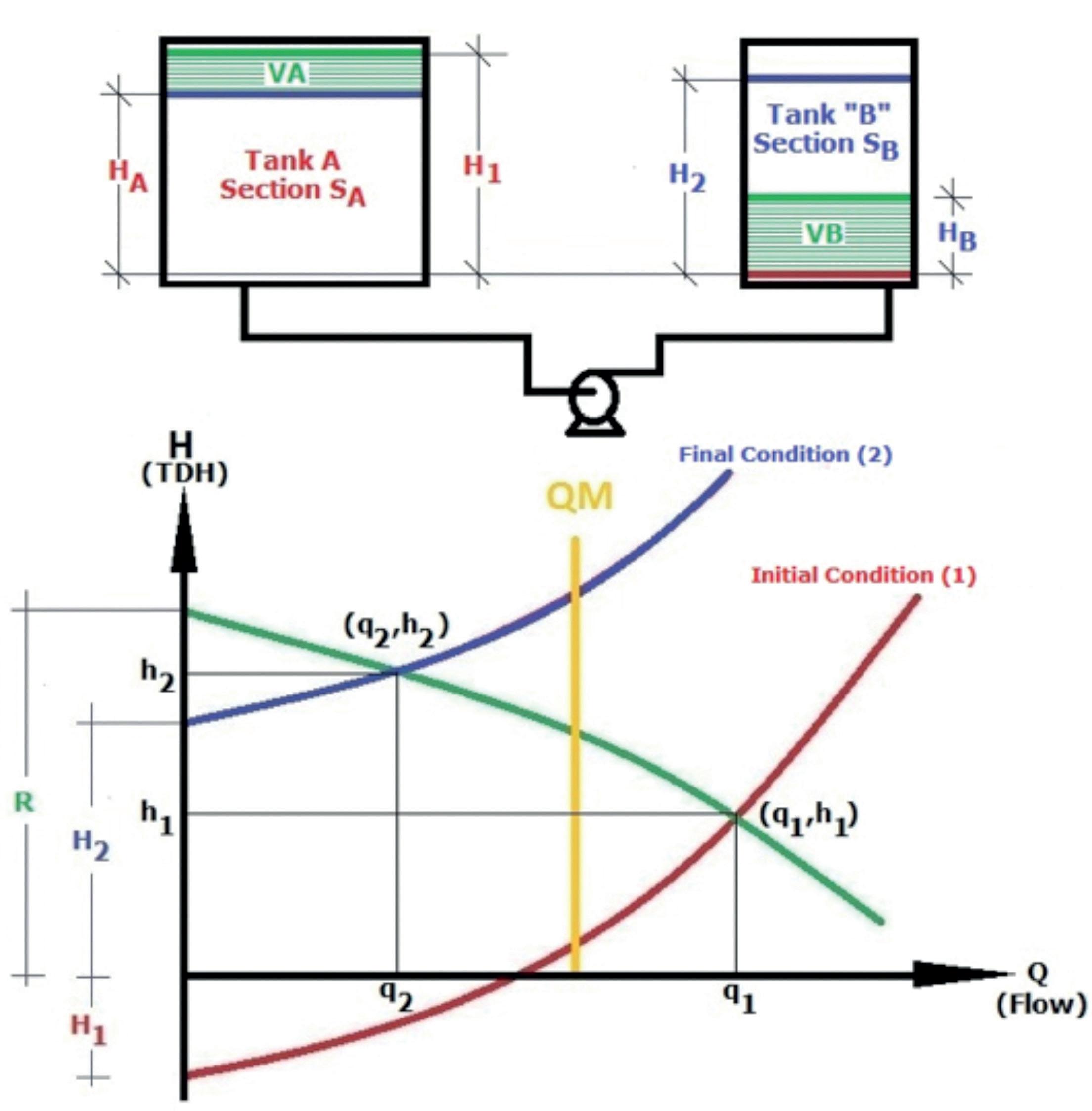
Seasonal changes can seriously threaten a pump’s effectiveness at a liquid-terminal, especially if viscosity is impacted by changing seasonal temperatures.
Further, terminal leases may change over time and new arriving liquids might be different viscosities than those originally anticipated. In either of these scenarios, varying viscosity impacts certain pumps negatively, leaving them ineffective to transfer liquids. Expensive fluid heating and circulation systems are often added to control viscosity. These auxiliary systems add additional operational and maintenance challenges to the terminal as well as overall costs to accommodate a particular pump’s weaknesses.
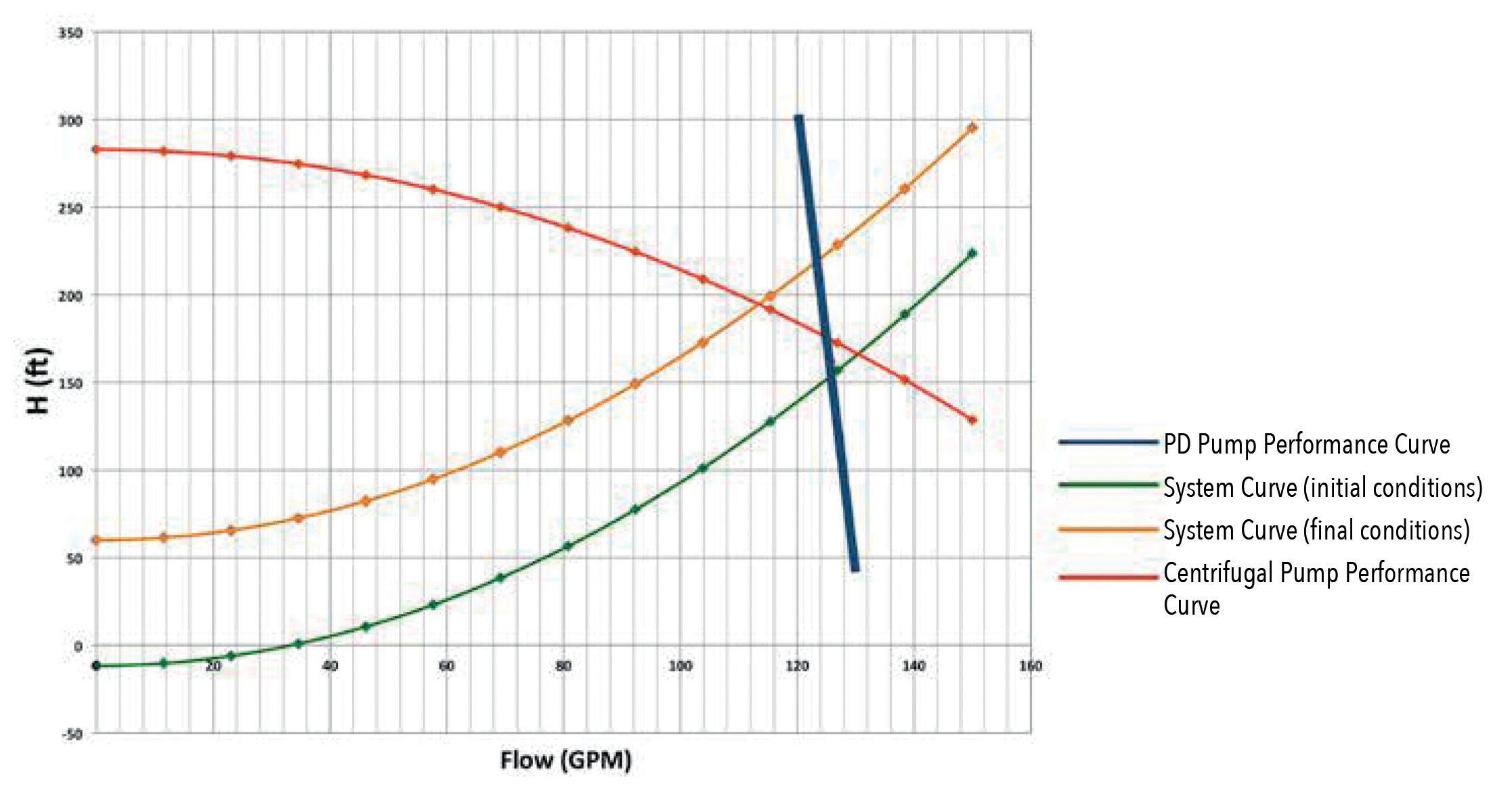
Startup problems can occur when a pump is not flooded. Whenever a supply pipe segment is empty, its air must be evacuated and compressed downstream to draw a full liquid column from the supply source to the pump. In this situation, a self-priming pump is needed. Self-priming centrifugal pumps are actually not self-priming because they require pre-priming of the pump casing. Positive displacement pumps, which are inherently self-priming, also sometimes require pre-priming in cases that the pump cannot dry run (i.e. screw, progressive cavity). Expensive vacuum and external priming systems can be added to augment weaknesses of particular pumps, but these auxiliary systems add unnecessary cost and complexity to a system.
Figure 1. For a fair and quantifiable comparison between different pumping technologies, the range of operation of the centrifugal pump and the equivalent PD pump must be fully defined.
The 2023 API Storage Tank Conference will give attendees an opportunity to learn about new and existing industry codes and standards, and to hear about emerging trends from industry experts. This conference offers over 25 sessions addressing the needs of individuals involved in production systems, pipelines, terminals, refining, and storage facilities. Each day focuses on presentations relevant to upstream, midstream and downstream.

When liquids have settled in a tank for long durations, viscosity and density differences can develop and stratify into liquid layers. It is also common for solids and sediment to settle at the bottom of the tank – or the liquid heel. A pump that cannot accommodate solids or a range of viscosity and density is ineffective at a terminal, because it will reduce in capacity and may fail prematurely. Further, most pumps are unable to withdraw the complete storage volume, leaving behind a liquid heel and residual fluid throughout the pipe network. Operators solve this problem by supplementing the process with pigging systems and portable submersible pumps, adding unnecessary cost and complexity to their operations.
The ultimate waste of time is equipment downtime, like a barge parked along a river dock awaiting a pump that is out of service for reliability reasons. In any of the aforementioned categories, a terminal’s operating conditions can negatively impact certain pump types, and reduce a pump’s mean time between maintenance (MTBM) and mean time between failure (MTBF). If pump selection does not consider the expected dynamic environment at a liquid-terminal, the terminal will have higher total cost of ownership, decreased reliability and less profitable operations. A poorly applied pump will cost time and profitability.
All of these challenges can be solved with a streamlined and reliable pump that keeps tanks, hoses and piping functioning properly, avoiding costly spillage, delays and cross-contamination during unloading, transferring and transporting.
Because the pump acts as a link in the supply chain for the liquid-terminal industry, when a pump cannot effectively function, the entire operation suffers, negatively impacting many other industries that heavily rely on liquid commodities. This adverse effect trickles down the supply chain until billions of people who depend on the various liquid resources become affected. A drastic outcome like this can be avoided by applying advanced pump technology.
While many pump technologies are installed within liquid-terminal applications, positive displacement sliding vane pump technology can meet strict federal regulations and solve the many challenges of the liquid-terminal industry.
Positive displacement sliding vane pump technology was invented in 1899 by Robert Blackmer as an enhancement to the existing gear technology that was available at the time. Since then, sliding vane pump technology has provided unique functional advantages, such as suction lift, self-prime, line stripping, product recovery, viscosity, and vapour flexibility, as well as bi-directional flow. Vane technology sets the standard for the world’s most complex and crucial operations, offering solutions for the liquid-terminal industry.
Sliding vane pump technology is designed for reduced energy consumption, operation and maintenance costs, as well as easy optimisation. Maintenance parts are low cost and accessible, allowing for easy replacement without needing to
remove the pump from the piping system. Sliding vane pumps are designed for dry-run and self-priming capabilities, eliminating the need for expensive priming systems, fluid conditioning systems, tank circulation systems, and pump monitoring systems.
Offering flow rates that are proportional to the pump’s speed – up to 2000 gal./min (7580 L/min) – sliding vane pumps can generate high pressure in low-flow applications without the need for multiple stages or pump sets.
Vane pumps are also unaffected by variances in pressure. Designed for viscosity flexibility, sliding vane pumps can handle thin liquids, such as gasoline, ammonia, solvents and more, along with liquids with viscosities up to 25 000 cSt without requiring expensive heating systems.
The unique sliding vane design prevents vane pumps from wearing in or derating in flow rate. Instead, vane pumps sustain ‘new pump’ flow capacity throughout the life of the pump. This means that an old pump will not take a longer time to transfer liquids. Instead, the time it takes a vane pump to transfer liquids at a terminal will be reliable and consistent seasonally and throughout a pump’s lifespan.
Vane pumps allow for expected dry run and have excellent vacuum, allowing for priming of long pipe networks (+100 m length / +300 ft length). They have high-suction lift that exceeds 25 ft (7.6 m), which provides for both top and bottom offloading, below ground storage, line stripping of product between batches, and recovery of liquid heel. Both tanks and piping systems can be cleared of liquids, solids and residual product. Vane pumps are bi-directional, allowing users to return liquid to the supply tank before disconnecting hoses.
Simply put, sliding vane pumps provide operational functions and benefits that other pump technologies cannot provide. This is especially beneficial within the dynamic environment of a liquid-terminal. Vane pumps reduce the time it takes to transfer liquids between tanks, accommodate changing system dynamics, and make liquid-terminals more profitable.
With nearly 1600 terminals in the US responsible for storing and transferring liquid commodities, the importance of versatile pump technology cannot be stressed enough. Time is critical for the demanding liquid-terminal industry. Storing and transferring raw materials and end products involves complying with strict federal regulations that demand modernised and streamlined technology. Increasing the speed and accuracy of loading and unloading while minimising the amount of wasted product is the key to their success. When terminal operators outfit their terminals and tanks with effective and reliable pump technology, they create a significant competitive advantage that allows them to strengthen customer relationships and uphold their reputation as a reliable operation in the industry.
Positive displacement sliding vane pumps provide a safe, reliable and effective technology that solves costly and hazardous challenges, while also helping to protect their most important commodity – time.


Edward Cass is a chemicals and engineering professional with more than a decade of experience in specialty chemical processing and applications. Edward holds a B.Sc. in chemistry from Bloomsburg University of Pennsylvania, US, and is currently Technology Manager at Paratherm Heat Transfer Fluids. Edward’s experience includes reactive and hazardous chemistries, pyrophoric gas processing, and formulation of synthetic lubricants. Edward has authored several articles and webinars on heat transfer fluid maintenance and performance and holds a patent for a specialised lubricant composition.
0 1 What are heat transfer fluids and how do they work?
Heat transfer fluids (HTFs) may also be referred to as hot oils, thermal fluids, thermic or thermal oils. Regardless of what they are called, the technology and working principles are the same. Heat transfer fluids are specialised fluid media designed to indirectly transfer thermal energy, by virtue of heating or cooling, to or from a manufacturing process.
The major advantages of thermal fluids is that they enable precision temperature control, and are capable of high operating temperatures at low system pressures.
02 When should heat transfer fluid be analysed?
As part of a preventative maintenance programme, it is standard practice to analyse the fluid at least once per year to ensure critical properties are within optimal ranges.
It is also recommended that the fluid be tested any time that an operating anomaly is experienced, or any time that fluid is replaced or topped off.
03 What are the main challenges for the industry when analysing fluid technology and performance across the workflow?
There are a lot of options to choose from when shopping for a heat transfer fluid. One challenge is selecting a fluid that is properly matched to the application requirements to meet or exceed performance expectations. Other challenges include knowing how to maintain and operate the system, and how to analyse and resolve performance issues when they arise.
04 How do heat transfer fluids degrade?
Heat transfer fluids can degrade in two ways.
First, if a hot fluid is exposed to air for a longer period of time, oxidation takes place. The resultant
acids have poor thermal stability and get further degraded at comparatively lower operating temperatures, e.g. 400°F. Acute oxidation results in heater buildups, sludge, and exceptionally high viscosity, i.e. fluid becoming thicker, at atmospheric temperature.
Second, overheating takes place as a result of heating a fluid above the maximum film temperature specified by the fluid manufacturer. The maximum film temperature is the fluid temperature on the inner wall of the heater tube or on the surface of the electric element. Such extreme temperatures result in breaking apart or cracking of the fluid molecules, thereby decreasing the viscosity, i.e. thinner fluid. Cracking may also lead to pump cavitation. Solid carbon particles are formed as a result of extreme overheating. There are three primary degradation modes for heat transfer fluids.
n Oxidation occurs when warm or hot fluid reacts with oxygen in atmospherically vented expansion tanks. Oxidation leads to sludges, tars and solids accumulation that can have significant impacts on system performance and reliability.
n Thermal degradation occurs when fluid is overheated beyond its maximum recommended temperatures. Excessive thermal stress can cleave or ‘crack’ molecules into smaller fragments called low boilers, which can also recombine into higher molecular weight species known as high boilers. Accumulated low and high boilers can lead to loss of performance and efficiency, pump cavitation, as well as operational safety concerns due to lowered flash point and autoignition temperature.
n Contamination may also lead to premature fluid degradation. Contaminants may be inadvertently introduced by user error, environmental ingress, or process leaks. The effects of contamination may be minor or significant, depending on the nature of the contaminant.