SUMMER 2 023


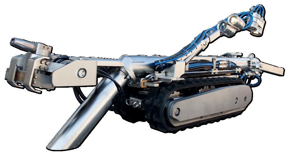
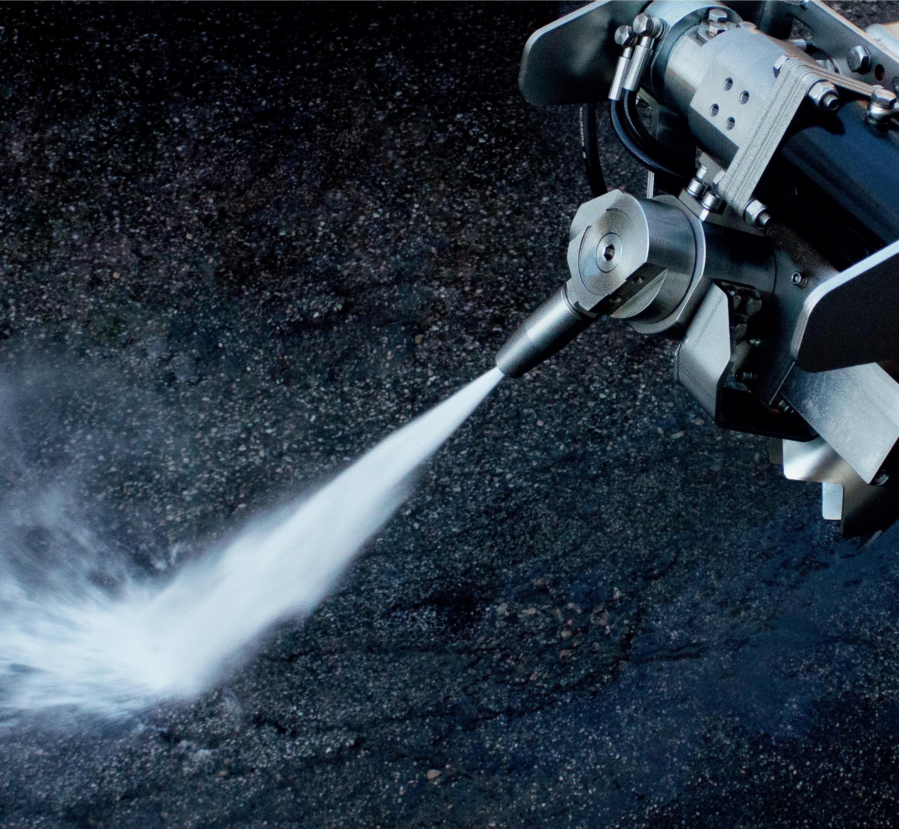
Gerotto has been a pioneer in engineering and manufacturing robotic tank cleaning solutions since 2002. A cutting-edge range of no-man entry robots that helps contractors and asset owner to reach the most demanding performances in explosive environments.
John

Ryan Thompson, Emerson, USA, explains how even the most experienced terminal schedulers can increase peak operational efficiency with the help of digital twin-based scheduling and optimisation software.
Aidan Doherty, Re-Gen Robotics, UK, details how terminal operators can improve safety and cut maintenance costs by applying smart tank cleaning solutions.
Edoardo Marangoni, Alberto Feletto, Daniel Devò and Alessandro Gerotto, Gerotto Federico Srl, Italy, analyse the genesis of robotic technologies for tank cleaning, and consider various options that are available to the market.
Bottoms
Danny Constantinis, EM&I Group, Malta, discusses some innovative solutions to the challenge of safe tank inspection.
39 Bunkering
Tariq Boussouara, TÜV SÜD National Engineering Laboratory, explains why the use of mass flow meters for fuel bunkering is likely to become increasingly widespread in the future.
Dandee Bacani, Endress+Hauser, Japan, examines how efficient instrumentation can help predict rollover events and minimise potential damage.
45 Leak detection for LNG tanks
Julian Yeo, United Electric Controls, USA, considers how it is possible to learn lessons from past incidents in the LNG sector to create a systematic approach towards leak detection.
49 The tank breather valve conundrum
Ewart Cox, Assentech, UK, outlines the importance of accurately measuring and reporting on the volume of leakage from tank breather valves.
53 Battery powered
Anthony Vangasse, Rotork, UK, explores how modern battery technology improvements within electric valve actuation can help a site to maintain an optimum level of operations.
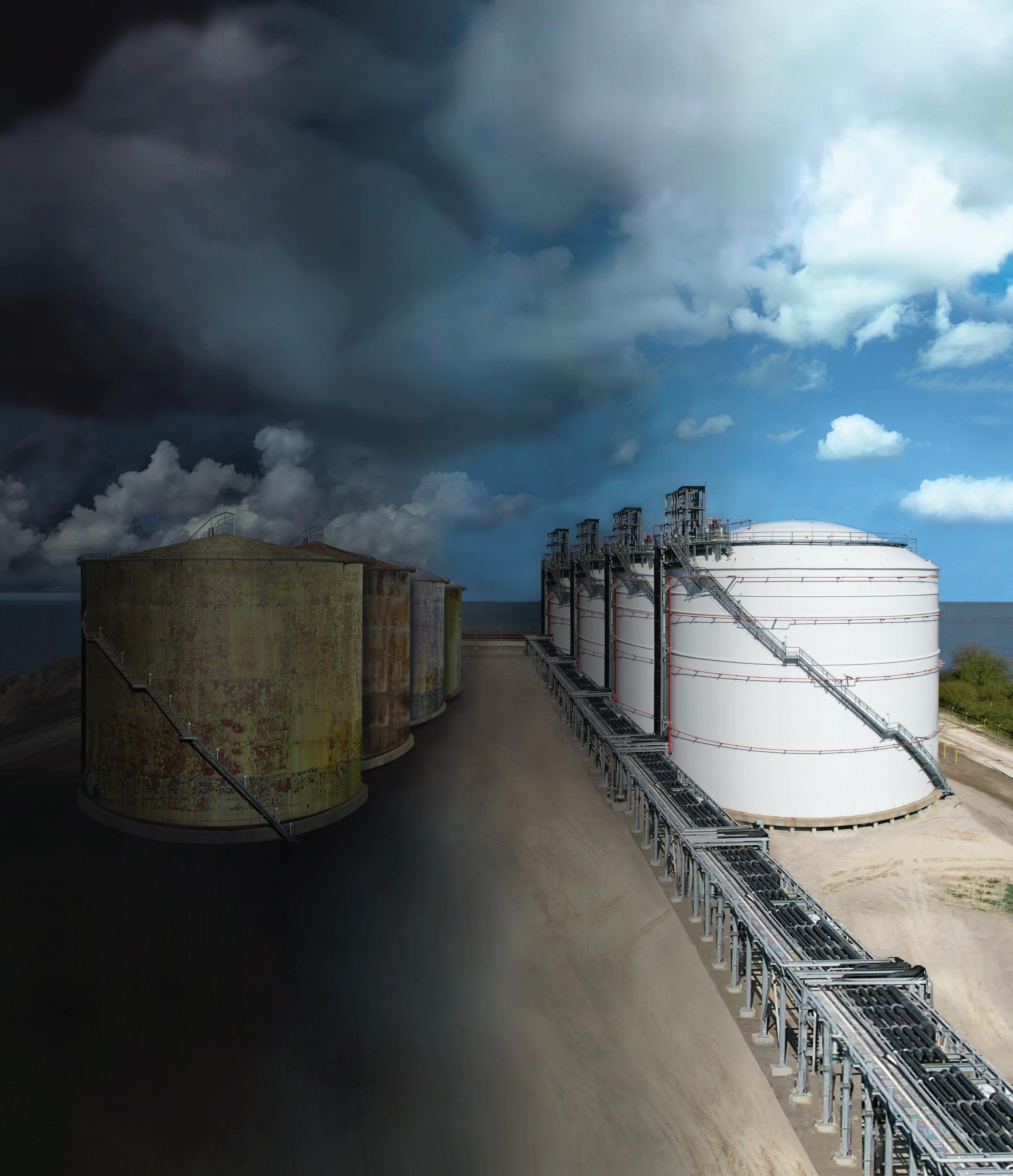
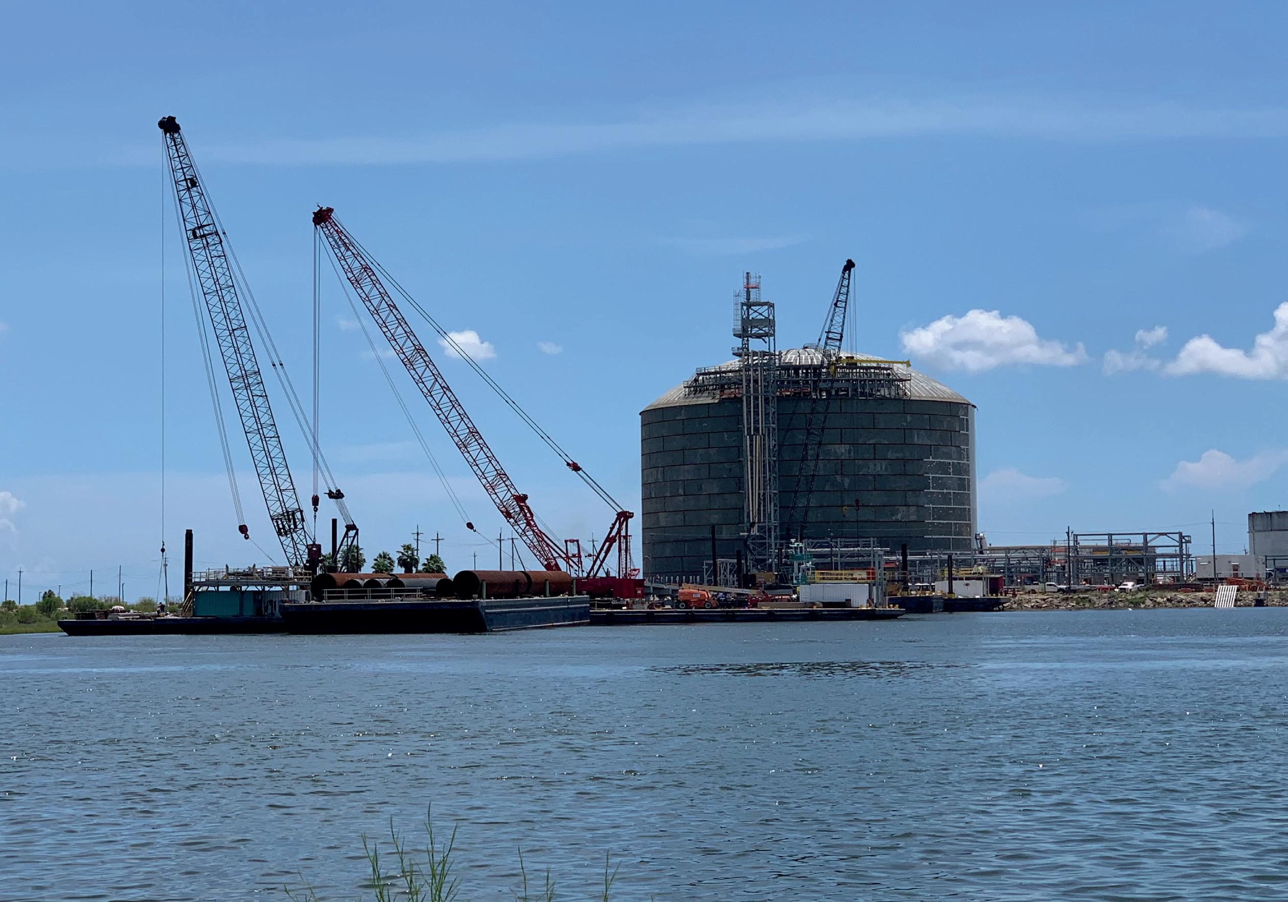
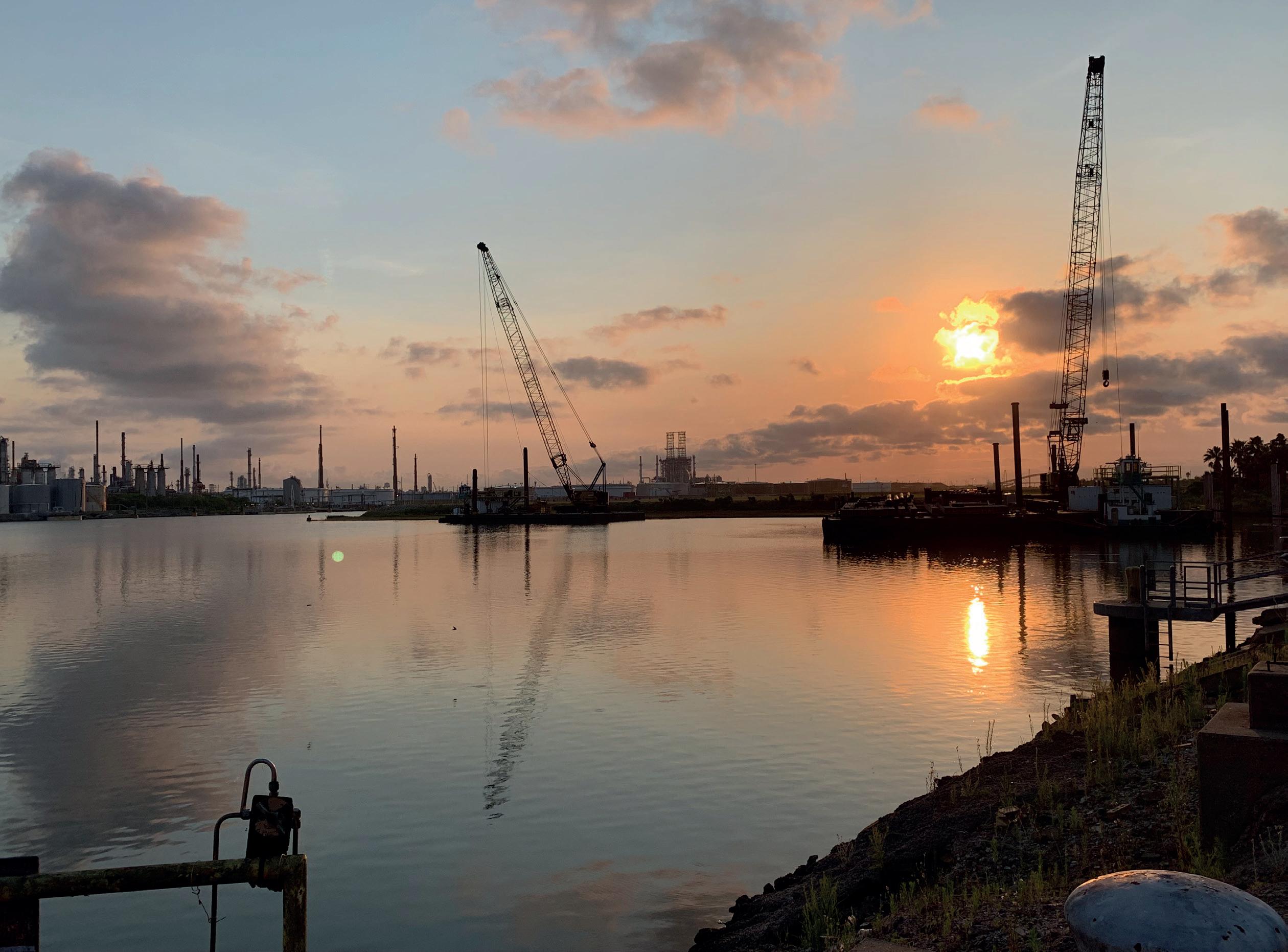
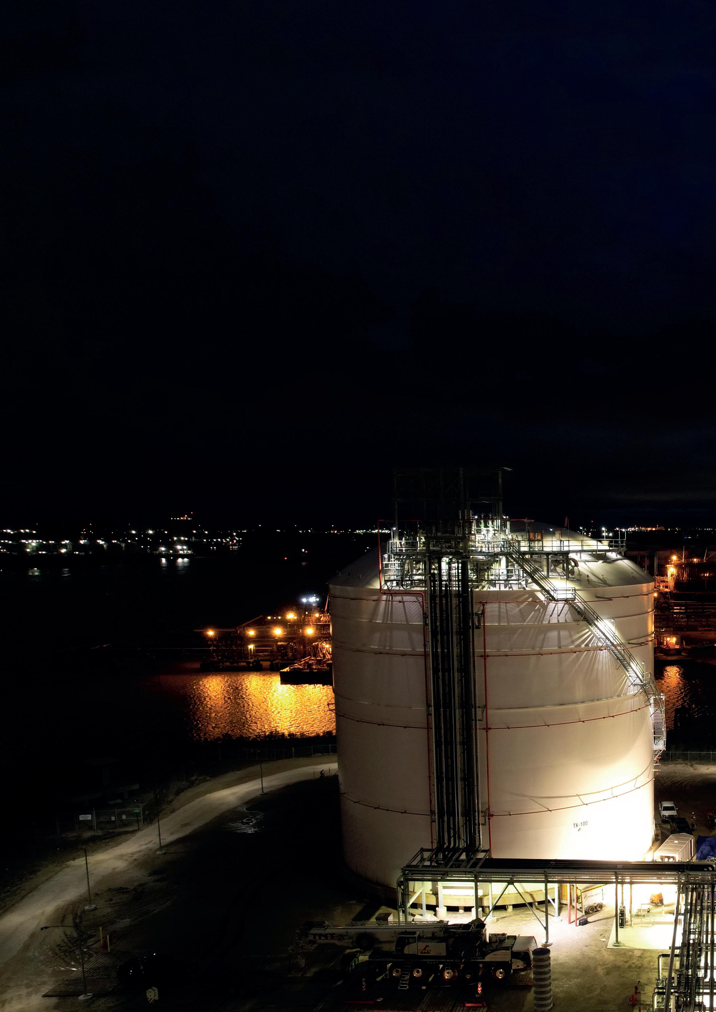
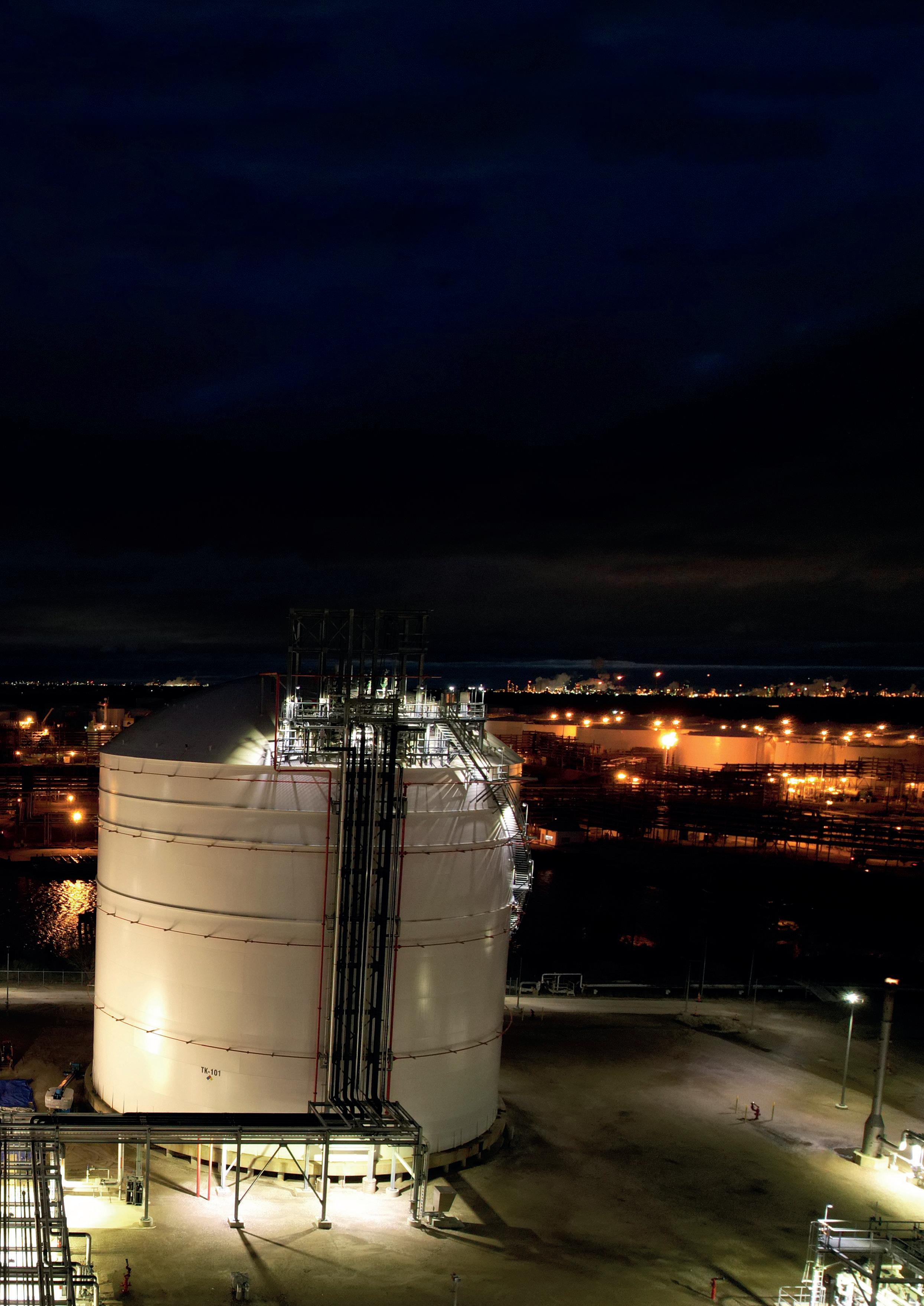
Gale force winds from the energy trilemma are bearing down on the liquid hydrocarbon terminal industry. American Tank & Vessel Inc. (AT&V) believes these winds possess the energy to propel the industry into a profitable transition. For more information, please refer to the article ‘A clean energy future for liquid terminals’ on p. 14 of this issue.


MANAGING EDITOR James Little james.little@palladianpublications.com
SENIOR EDITOR Callum O’Reilly callum.oreilly@palladianpublications.com
ASSISTANT EDITOR Bella Weetch bella.weetch@palladianpublications.com
SALES DIRECTOR Rod Hardy rod.hardy@palladianpublications.com
SALES MANAGER Chris Atkin chris.atkin@palladianpublications.com
SALES EXECUTIVE Sophie Birss sophie.birss@palladianpublications.com
PRODUCTION MANAGER Kyla Waller kyla.waller@palladianpublications.com
EVENTS MANAGER Louise Cameron louise.cameron@palladianpublications.com
EVENTS COORDINATOR Stirling Viljoen stirling.viljoen@palladianpublications.com
DIGITAL CONTENT ASSISTANT Merili Jurivete merili.jurivete@palladianpublications.com
DIGITAL ADMINISTRATOR Leah Jones leah.jones@palladianpublications.com
ADMIN MANAGER Laura White laura.white@palladianpublications.com
CONTRIBUTING EDITORS
Nancy Yamaguchi Gordon Cope

SUBSCRIPTION RATES
Annual subscription £110 UK including postage /£125 overseas (postage airmail).
Two year discounted rate £176 UK including postage/£200 overseas (postage airmail).
SUBSCRIPTION CLAIMS
Claims for non receipt of issues must be made within 3 months of publication of the issue or they will not be honoured without charge.
APPLICABLE ONLY TO USA & CANADA
Tanks & Terminals is a supplement of Hydrocarbon Engineering. Hydrocarbon Engineering (ISSN No: 1468-9340, USPS No: 020-998) is published monthly by Palladian Publications Ltd GBR and distributed in the USA by Asendia USA, 17B S Middlesex Ave, Monroe NJ 08831.
Periodicals postage paid New Brunswick, NJ and additional mailing offices. POSTMASTER: send address changes to HYDROCARBON ENGINEERING, 701C Ashland Ave, Folcroft PA 19032
15 South Street, Farnham, Surrey
GU9 7QU, UK
Tel: +44 (0) 1252 718 999
Fax: +44 (0) 1252 718 992
Many of the bulk liquid products handled by ILTA member companies demand special precautions due to their flammable properties. While significant fire events at terminals are rare, responsible facility management demands that terminal operators maintain capabilities to respond quickly and effectively to fire events when they do occur. For decades, the tank storage industry has relied upon aqueous film-forming foams (AFFF) to protect communities, workers, commodities, and infrastructure from potentially dangerous fire hazards and environmental risks from fire events or spills, such as air pollution. The effectiveness of these foams was attributable to the unique characteristics of the perfluoroalkyl and polyfluoroalkyl substances (PFAS) they contained.
ILTA firmly supports a safe, strategic, well-managed transition to fluorine-free, or PFAS-free, firefighting foams, while ensuring public and worker safety. We also recognise that significant barriers must be addressed before we can achieve a complete, industry-wide transition to safer alternatives.
Transitioning the liquid terminal industry’s existing stocks of firefighting foam to fluorine-free foams will require collaboration between regulators and industry stakeholders, including terminal owners and operators, firefighters, foam manufacturers, and disposal vendors. Alternative foams are not a drop-in substitute for AFFF. There are important research, development, deployment, training, disposal, and other activities that should be strategically thought through in developing a transition timeline. For example, to be effective, the replacement foams may require higher foam volumes, additional labour, and different application techniques and equipment. And we must allow time for coordination between these stakeholders for testing, training, equipment replacement, disposal, and other critical activities.
Terminal operators rely on the principle of mutual aid to ensure that they can provide adequate responses to incidents. During an event, neighbouring facilities may provide foam, equipment, or fire-fighting personnel. Importantly, due to the foam flow rates and potential contamination concerns, equipment prepared to deliver PFAS-containing foams cannot be used to deliver fluorine-free foams, and vice versa. For the largest fires, foam may be provided from other facilities across the region or even from across the country. This interdependence of terminals means more time is needed to eliminate PFAS-containing foams from our sector.
There are still challenges. We must ensure we do not introduce regrettable substitutes. Certification programmes, such as Green Screen, provide vital information about new alternatives. Moreover, there is no universally accepted method of safe disposal of PFAS-based firefighting foams. Incineration of PFAS chemicals is banned in several states, and a moratorium on PFAS incineration is in place at Department of Defense facilities. While new technologies to destroy PFAS in firefighting foams have recently entered the marketplace, more work is needed to validate these technologies for all legacy foams.
A coordinated transition to fluorine-free firefighting foams is essential to safe incident response across the liquid terminal industry. ILTA will continue working with a coalition of industry, firefighters, and environmental stakeholders to advocate for a national phase-out of fluorine-free foams on a practical, achievable timeline. It is vital that we avoid a piecemeal approach across different states.


Royal Vopak and AltaGas Ltd have announced the execution of definitive agreements for a new 50/50 joint venture (JV) to further evaluate development of the Ridley Island Energy Export Facility (REEF), a large-scale LPG and bulk liquids terminal with marine infrastructure on Ridley Island, British Columbia, Canada. REEF will have the capability to facilitate the export of LPGs, methanol, and other bulk liquids that are vital for everyday life.
TotalEnergies has announced the delivery of the first LNG cargo to the Dhamra LNG terminal, located in Odisha, India. The terminal is owned and operated by Adani Total Private Ltd (ATPL), a 50/50 joint venture (JV) between TotalEnergies and Adani.
Hyphen Hydrogen Energy has signed a Letter of Intent (LOI) with Koole Terminals, covering the proposed import of green ammonia into northwestern Europe. Hyphen plans to supply its customers using the import terminal being developed by Koole Terminals, which is located in the Port of Rotterdam, the Netherlands.
Sacyr Proyecta has been confirmed as the engineering company for a new liquified gases terminal that is currently being developed by Hanseatic Energy Hub (HEH) in Stade, Germany. The terminal will have a regasification capacity of 13.3 billion m3, and two LNG storage tanks with a capacity of 240 000 m3.
To keep up-to-date with the latest news and developments in the storage sector, visit www.tanksterminals.com and follow us on our social media platforms

10 13 July 2023
LNG2023
Vancouver, British Columbia, Canada www.lng2023.org
05 08 September 2023
Gastech Singapore www.gastechevent.com
26 28 September 2023
Turbomachinery & Pump Symposia Houston, Texas, USA tps.tamu.edu
02 05 October 2023
ADIPEC Abu Dhabi, UAE www.adipec.com
09 12 October 2023
API Storage Tank Conference & Expo Denver, Colorado, USA events.api.org/2023-api-storage-tank-conference-expo
05 07 December 2023
16th Annual National Aboveground Storage Tank Conference & Trade Show
The Woodlands, Texas, USA www.nistm.org
12 14 March 2024
StocExpo Rotterdam, the Netherlands www.stocexpo.com
Contributing Editor, Gordon Cope, considers how recent geopolitical events have opened up a range of opportunities for the tanks and terminals sector in North America.

Although the Ukraine conflict is thousands of kilometers away from North America, its consequences are reverberating throughout the continent. Traditional international markets for crude and refined products are being upended, and LNG has been given a new lease of life. Investments in renewable fuels, such as green hydrogen and ammonia, are also experiencing exponential growth. And the consumption of energy in major markets such as China has fully recovered from the COVID-19 pandemic. All of this spells new opportunities for the tanks and terminals sector.

Canada’s total crude production exceeds 5 million bpd. The oil sands of Alberta are the largest single source, with 3.3 million bpd, and output is expected to rise to 3.6 million bpd over the next decade.
Several major crude terminals exist in Alberta to store production that is destined for
export to the US. The largest is in Hardisty, which sits astride several major crude pipelines. Crude producers, pipeline companies, and infrastructure firms operate at the site, including Enbridge (16 million bbl), Husky (4.9 million bbl) and Gibson Energy (13.5 million bbl). Gibson alone is looking to spend up to CAN$125 million on tank-related expansions in 2023, and CAN$150 million – 200 million/yr for the foreseeable future.
Canada exports approximately 4 million bpd to the US, which is expected to rise to 4.2 – 4.4 million bpd by 2026. Pipeline expansions that are in progress will add almost 1 million bpd capacity by 2025, and crude-by-rail capacity is continually growing. In order to develop alternate export markets in Asia, the Trans Mountain pipeline, which runs from Alberta to tidewater in Burnaby, British Columbia (B.C.), is being expanded from 350 000 bpd to 890 000 bpd, with completion expected in 2024. The Burnaby tank terminal and nearby Westridge marine terminal are also undergoing expansion. Formerly, the Burnaby terminal had 13 tanks with a capacity of 1.6 million bbl; the expansion will add 13 more tanks, and double capacity. The Westridge marine terminal was able to handle one Aframax tanker (approximately 600 000 bbl); a new dock complex will allow the facility to load up to three Aframax tankers. When completed in 2024, the new infrastructure will be able to handle around three dozen vessels per month.
For over a decade, various developers have been promoting LNG projects in B.C., which is thousands of kilometers closer to Asia than the Gulf of Mexico. LNG Canada, led by Shell, is building a plant in Kitimat. The first phase of 14 million tpy is scheduled for completion in 2025. Construction of the 2.1 million tpy Woodfibre LNG plant near Squamish is set to begin in late 2023, with a completion date in 2027. In March 2023, the B.C. government approved the construction of the Cedar LNG project, also near Kitimat. The CAN$2.4 billion floating LNG (FLNG) facility, which is majority-owned by the Haisla First Nations, is expected to produce up to 4 million tpy.
Energy infrastructure in the US Gulf Coast (USGC) is undergoing a transformation. During the latter half of the 20th century, an immense refinery/petrochemical complex arose, stretching from Texas to Louisiana. Oil tankers delivered crude from Mexico and Venezuela via Aframax tankers; refined products were then shipped by tankers, rail and dedicated pipeline systems to consumers on the Eastern Seaboard.
All of that changed with the advent of unconventional oil and gas. Operators began to pump millions of barrels of crude and billions of cubic feet of natural gas from the shale formations in Texas and Louisiana, upending traditional supply and demand. The Ukraine conflict has also spurred changes. According to the US Energy Information Administration (EIA), USGC (PADD 3) exports averaged 2.48 million bpd in 2021; by late 2022, that number had grown to over 4 million bpd, with the majority of the increase going to Europe to offset the ban on Russian seaborne crude.
The need for new infrastructure in the USGC can be roughly broken into three aspects. First, the light, low-sulfur crude being produced from the Permian Basin is unsuited to the heavier slates being used by domestic refineries, but is in demand in other jurisdictions, including China. Normally, US crude travelling to China is loaded aboard 2 million bbl very large crude carriers (VLCCs), which then take a seven-week journey around the Cape of Good Hope. Due to the fact that USGC ports are configured for Aframax, they cannot load VLCCs at dockside, and must rely on ‘reverse lightering’, in which smaller tankers top up VLCC cargoes offshore. As a result, exporters have been angling for new port infrastructure to handle VLCCs.
In November 2022, the Biden Administration approved the development of the Enterprise Products Partners’ Sea Port Oil Terminal (SPOT) in Freeport, Texas, approximately 30 km south of Houston. The new 2 million bpd offshore terminal will be able to accommodate VLCCs. Enbridge subsequently announced that it was proceeding with the Enbridge Houston Oil Terminal (EHOT) at the southern end of its Seaway Pipeline. The first phase of the new facility will have up to 2.5 million bbl of crude storage, with the potential to expand to 15 million bbl. Plans are underway to connect EHOT to SPOT.
Second, finished petroleum products from the USGC are growing in demand worldwide. According to the EIA, in 2021, prior to the Ukraine war, gasoline, diesel and jet fuel exports
from the region averaged 2.34 million bpd. By late 2022, they had exceeded 3 million bpd, and are expected to increase further this year as ExxonMobil’s 250 000 bpd expansion of its Beaumont, Texas refinery ramps up to full production of 619 000 bpd.
The majority of the refined product export increases are going to Mexico, Argentina and Brazil, which do not have sufficient refining capacity to meet increased domestic demand. Most of the exports are handled by mid-size tankers which fit into current USGC terminals, but the increased traffic requires greater clean tank capacity dockside.
Third, the immense quantities of natural gas being produced in association with unconventional crude became an inexpensive feedstock and energy source for the development of LNG. USGC-area LNG projects are currently consuming over 13 billion ft3/d, placing the US in the running as the world’s top LNG exporter. The Ukraine war has motivated European utilities to seek long-term LNG contracts, sparking North American firms to announce new projects. Over the next three years, capacity is expected to increase by a combined 5.7 billion ft3/d as new major capacity comes onstream. Projects that are underway or planned include the following:
n Sempra is developing the Port Arthur LNG project, located on the Sabine-Naches ship channel (which marks the border between Texas and Louisiana). Phase 1 foresees two trains with a capacity of 10 million tpy (1.3 billion ft3/d). ConocoPhillips has taken a 30% stake in the project and a commitment to take 5 million tpy, as well as supply feed gas through its regional pipeline system.
n Qatar Energy and ExxonMobil are currently constructing the Golden Pass LNG project, located at an existing LNG import terminal at Sabine Pass, Texas. The US$10 billion complex could eventually have up to 18 million tpy capacity. Start-up is expected in 2024.
n Energy Transfer plans to build the Lake Charles LNG project at its current LNG import site in Louisiana. The company intends to build three LNG trains with a total capacity of 6.45 short tpy.
n Venture Global has announced plans to build the Plaquemines LNG terminal in Louisiana, 30 km south of New Orleans. Phase 1 will include 18 modular mini-trains with a total of 11.3 million short tpy capacity. Phase 2 will almost double capacity to 20 million t. The total cost of both phases is estimated at US$20 billion.
Greenfield LNG projects typically require extensive tank and terminal infrastructure. The Plaquemines project, for instance, envisions two 200 000 m3 LNG storage tanks and berthing facilities capable of handling three tankers simultaneously. New demand in the projects cited above will cost several billion dollars. While most existing terminals can handle standard 150 000 m3 LNG tankers, a new generation of 250 000 m3 tankers (similar in size to VLCCs) is on the drawing boards; ports will have to make extensive draft and pier improvements to accommodate them.
In addition, regional storage infrastructure needs to be added to handle the billions of cubic feet of additional
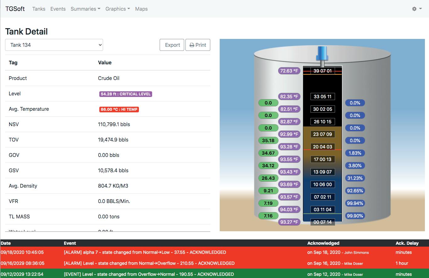
Emerson’s inventory management software provides instant insight to tank operations worldwide. No matter the time or place, management can always stay on top of critical assets, leading to better and faster decision making.
Learn more at www.emerson.com/rosemounttankmastermobile

gas requirements. In March 2023, Enbridge announced that it was purchasing the Tres Palacios gas storage facility, located 50 km southwest of Houston, for US$335 million. The facility currently has the capacity to store up to 35 billion ft3 of gas in three salt caverns, with a request before the US Federal Energy Regulatory Commission (FERC) to expand capacity by a further 6.5 billion ft3 by building a fourth cavern. In a statement, Enbridge said the purchase would aid its customer’s LNG exports.
While critics warn that US LNG facilities might find themselves stranded in the coming decades as the world converts to renewables, staunch environmental proponents are investing heavily in the sector, regardless. For instance, Germany, which is highly vulnerable to dependence on Russian gas, is busy commissioning FLNG regasification terminals and signing long-term contracts that allow LNG companies to finance construction. “Energy supply will no longer be taken for granted,” said Simon Flowers, Chairman and Chief Analyst at Wood Mackenzie, a consultancy. “No country can ever again allow itself to become reliant on imported energy from a single supplier. In future, energy security will be about the diversity of fuels and sources, and the primacy of domestic resources.”1
Net zero regulations in Canada and the US are also incentivising companies to invest in environmentally-friendly projects that create renewable fuels in North America. In February 2023, German-based RWE formed an alliance with LOTTE Chemical, of South Korea, and Japan’s Mitsubishi, to build a clean ammonia production and export facility in the Port of Corpus Christi, Texas. The plan is to build a series of units with a final capacity approaching 10 million tpy by 2030. Output will be in the form of both blue and green ammonia, and will be exported to Asia and Europe for use as both fuel and a source of renewable hydrogen.
In February 2023, EverWind, based in Nova Scotia, Canada, received approval from the provincial government to build a 300 MW hydrogen electrolysis and green ammonia plant in Port Hawkesbury. The CAN$6 billion project is intended to supply the German market by 2025.
Nutrien, a Canadian fertilizer company, is working in collaboration with Belgian shipping company EXMAR to develop an ammonia-powered shipping vessel. In late 2022, the company announced that it has plans to build the world’s largest clean ammonia facility at its existing complex in Geismar, Louisiana, near tidewater ports in New Orleans. Currently undergoing FEED, the 1.2 million tpy plant would permanently remove up to 90% of CO2 emissions using carbon capture and sequestration (CCS) technology. A final investment decision (FID) is expected by 2023; full production could commence by 2027.
ExxonMobil is advancing plans for a massive, low-carbon hydrogen and ammonia production facility, located in its Baytown, Texas complex. In January 2023, it contracted with Technip Energies to conduct FEED in order to make an FID by 2024. When construction is finished in 2028, the new facility will produce up to 1 billion ft3/d of blue hydrogen by capturing and sequestering up to 98% of CO2 emissions.
The output allows ExxonMobil and third-party customers to produce low-carbon fuels and products.
Cresta Fund Management, a private equity firm, purchased the idled Come-by-Chance refinery in Newfoundland, Canada. The 135 000 bpd refinery, to be called Braya Renewable Fuels, will focus initially on producing 14 000 bpd of sustainable aviation fuel (SAF). Further plans include doubling capacity to 27 000 bpd. Braya is currently in discussions with ABO Wind to supply 35 000 tpy of green hydrogen.
Yara, a fertilizer company based in Norway, is teaming up with Enbridge to build a blue ammonia plant in Corpus Christi. The US$2.9 billion facility will produce up to 1.4 million tpy using carbon capture. The output will be used for low-carbon fertilizers, shipping fuel and utility power. Salt dome structures are widespread throughout sedimentary formations in Texas. Researchers at the University of Texas have determined that the large underground caverns are suitable for both temporarily storing hydrogen and permanently storing CO2 captured during blue hydrogen production.
Environmental complications surrounding energy terminals remain an issue. In early 2021, Phillips 66 and Trafigura received a permit to build the Bluewater Texas Terminal (BWTX) in the Port of Corpus Christi. The proposed terminal would be located 20 miles offshore from the Corpus Christi Ship Channel in water deep enough to allow up to 21 VLCCs to be loaded each month, with a total annual capacity of almost 400 million bbl. As part of the development, the US Environmental Protection Agency (EPA) issued a Clean Air Act permit allowing BWTX to emit approximately 19 000 short tpy of pollutants – primarily volatile organic compounds (VOCs). Environmental groups protested, arguing that the project should fall under National Emission Standards for Hazardous Air Pollutants (NESHAP) for marine tank vessel loading operations, which calls for a 95% reduction in VOC emissions. The EPA agreed, and in September 2022 it revoked the permit and instructed Phillips 66 to withdraw and resubmit its application. Phillips 66 complied, including new equipment to reduce VOCs. The revised application is currently under review.
The future of the energy sector in North America is difficult to predict; one only has to see how an unexpected event such as the war in Ukraine can significantly impact plans. The conflict has, however, accelerated many of the energy-related changes already underway in North America, including growth in exports and new markets. When the potential for new renewable fuels is added into the mix, significant opportunities for tanks and terminals will abound through the coming decade.
Reference
1.
Global ammonia production is being affected by surges in natural gas feedstock prices and the halt of ammonia supply shipments due to the war in Ukraine. On the other hand, demand continues to grow to support food production, along with an increasing number of applications that can use ammonia to meet decarbonisation goals.
In 2022, the worldwide ammonia market was US$78 billion, with expected growth to almost US$130 billion by 2030.1 The US ammonia market is tracking this growth, with more than 621 000 t exported in the last six months of 2022 alone.2 This market growth presents a unique opportunity for terminal operators to explore the development of ammonia export terminals. However, balancing capital investment with the logistical factors of ammonia handling will be essential for export terminal project success.

Upfront planning and decision making are critical to terminal project development, and can directly shape project efficiency while lowering risk.
At the start of a project, operators should evaluate the location of upstream assets, existing terminal facilities, pipeline location, and water access. Whether planning for a new terminal or revamping an existing facility, deciding plant capacity and vessel class early will serve to guide the site selection strategy.
Export terminals also require an assessment of site topography, storm surge risks from hurricanes and flooding, levees, terminal equipment elevation requirements, and more. There are many different stakeholders interested in export terminal development. It is important to consider the required environmental, wildlife, water, safety and security rules and permits at the start of a project in order to help guide the scope and schedule.
The operating infrastructure, energy needs, and export volumes of an ammonia terminal are enormous. Refrigeration systems will commonly require tens of thousands of horsepower, with ships typically loading 40 – 55 million t of product at a time. Therefore, an ammonia export terminal must be engineered to precise
ChrisNiemeyer
andCaitlin
Geisinger, Burns & McDonnell, USA, explain how growth in the ammonia market presents a unique opportunity for terminal operators.
standards in the upfront design phase in order to safely and cost-effectively handle this toxic and highly flammable chemical.
Once the decisions have been made on plant capacity and vessel types, operators and designers must focus on essential operational requirements. These must be determined early due to the large volumes of energy, water and refrigeration that ammonia demands. In this conceptual design phase, each decision aims to strike a balance among the total installed cost of assets, operational efficiency, and safety.
Ammonia must be transported and stored in refrigerated environments. Therefore, at the outset, the terminal design must identify the availability, location and reliability of power and water needed for industrial refrigeration.
As part of the cooling system, operators must determine whether wet surface air coolers, cooling water condensers, or air coolers will be used. Considerations include evaluating efficiency, process temperatures achieved, space for assets, and energy requirements. For example, using condensed air instead of water for cooling could require up to 20% more electrical energy.
Ammonia export terminals demand consistent, round-the-clock electrical power. Evaluation of the site should consider proximity of grid interconnections and available voltage capacity. It is important to determine options to tap into the grid, as well as the potential for a full loop tap for higher reliability. If the site is remote, operators must determine the available energy sources, and whether onsite electrical power generation may be required. A holistic approach with the design firm and service provider is essential for an effective outcome.
Determining whether a terminal will use tank storage or direct load will have a cascading effect on decisions, cost and efficiency. Tank storage presents a large upfront investment but can help a terminal to manage inventory and cope with scheduling uncertainties. With steady ammonia supply into the tank, load swings can be better managed, and the set-up needs smaller supply pipelines and lower refrigeration requirements.
Direct load is limited by pipeline and refrigeration capacity, which can slow loading and increase dock time. A direct load design simplifies terminal design but requires large-diameter pipelines and higher horsepower refrigeration.
For projects that use tank storage, full containment tanks are preferred for ammonia storage. Although this will require a larger capital investment than for single-wall tanks, full-containment tanks take up less plot space and meet safety considerations and permitting regulations. This double-walled tank design, however, requires submersible loading pumps, which present certain considerations for engineering and maintenance. For example, tanks with capacities in the range of 300 000 – 900 000 bbl must be drained and inspected every 5 – 10 years.
Due to the critical nature of refrigeration for terminals, several design decisions must be made. Open-loop refrigeration (without heat exchangers) using the ammonia as the cooling medium allows for simpler design and lower power consumption. Closed-loop refrigeration can also be used with multiple refrigerant options; the process requires more equipment than an open-loop approach but can often better handle light ends or contaminants that end up at the terminal. An experienced design contractor can evaluate refrigeration options as well as compressor types, configuration and boil-off gas (BOG) management in order to identify the optimum solution.
With its high oxygen concentration, ammonia is a flammable gas that can create a jet flame if released. There is flexibility in many terminal design decisions, but the safe handling, storage and containment of ammonia must be the catalyst upon which design decisions are made.
Safety and site layout planning can go hand-in-hand. Because of the size of assets, power requirements, and safety mandates of ammonia export facilities, the layout of a terminal is critical.
The relative location of equipment, tanks, docks and thermal oxidisers should be based on spacing guidelines and project-specific operability and maintenance analysis. Refrigeration terminal decisions should use consequence-based modelling for toxic releases, fire, radiation, and potential blast contours.
Site layout options should be considered as process design and equipment decisions are made. Deciding on asset placement, electrical power, water access and dock unloading will adversely affect the efficiency of the terminal and unnecessarily drive up cost.

Early decisions on process choices, equipment preferences, safety strategies, and plot plan will greatly determine the project cost. Engaging with field-proven engineering resources that offer planning and design best practices and deliver credible cost estimates will help drive good decisions and, ultimately, savings. Not unlike a large tank ship, once an ammonia terminal project gets going, any course changes are complex and expensive.
1. 'Ammonia Market (By Product Form: Liquid, Gas, Powder; By Application: Fertilizers, Refrigerants, Pharmaceuticals, Textile, Others) - Global Industry Analysis, Size, Share, Growth, Trends, Regional Outlook, and Forecast 2022-2030', Precedence Research, (November 2022).
2. MULLINS, C., 'Viewpoint: EU demand to bolster US ammonia exports', Argus Media, (3 January 2023).
3. TULLO, A. H., 'Is ammonia the fuel of the future?', Chemical & Engineering News

As ammonia processes and technologies change, so does the carbon intensity of production. An informal colour scheme has been adopted for ammonia (and also applies to hydrogen) to communicate both the process used and the environmental impact.3
Conventional ammonia production, known as grey ammonia, uses the traditional Haber-Bosch process, and currently accounts for almost all ammonia output today. The method reacts atmospheric nitrogen and hydrogen, which is often generated from steam reformation of methane.
Conventionally-produced ammonia, where the carbon dioxide (CO2) byproduct is captured and stored, is called blue ammonia. While its carbon intensity is reduced, a range of opinions exist concerning the overall environmental benefit of blue ammonia.

Green ammonia is produced with hydrogen from water electrolysis that is powered by renewable or alternative energy. Investment and improvements in the technique for ammonia production are beginning to be widely adopted.
Not as well known, turquoise ammonia is produced by converting methane into pure carbon and hydrogen that then reacts with nitrogen.
can tailor to your requirements, produce 1 - 12 page formats, print colour or mono and more
Almost everyone in the liquid terminal industry would agree that resolving the energy trilemma (affordability, energy security, and environmental sustainability) may take up to 20 years. At the same time, investors are starting to distance themselves from the hydrocarbon industry, and publicly traded companies are faced with the challenge of satisfying a broad range of investors on the path forward. Therefore, the liquid terminal industry needs a plan to support positive economic results during the energy transition.
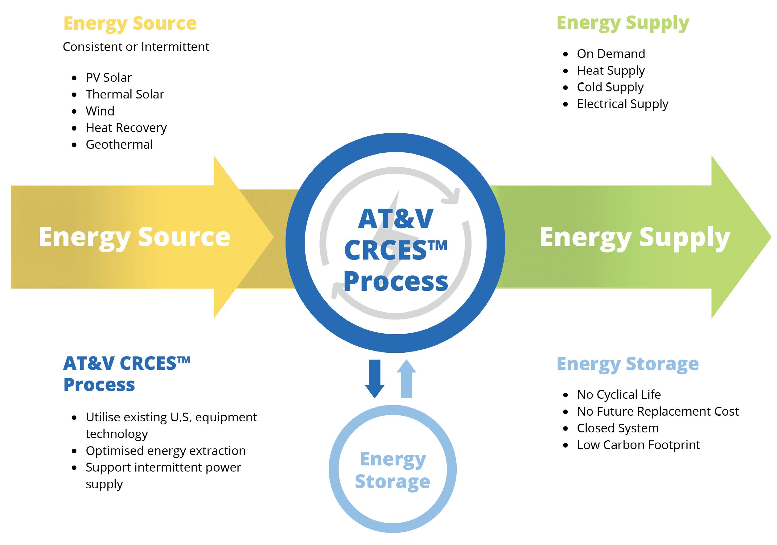
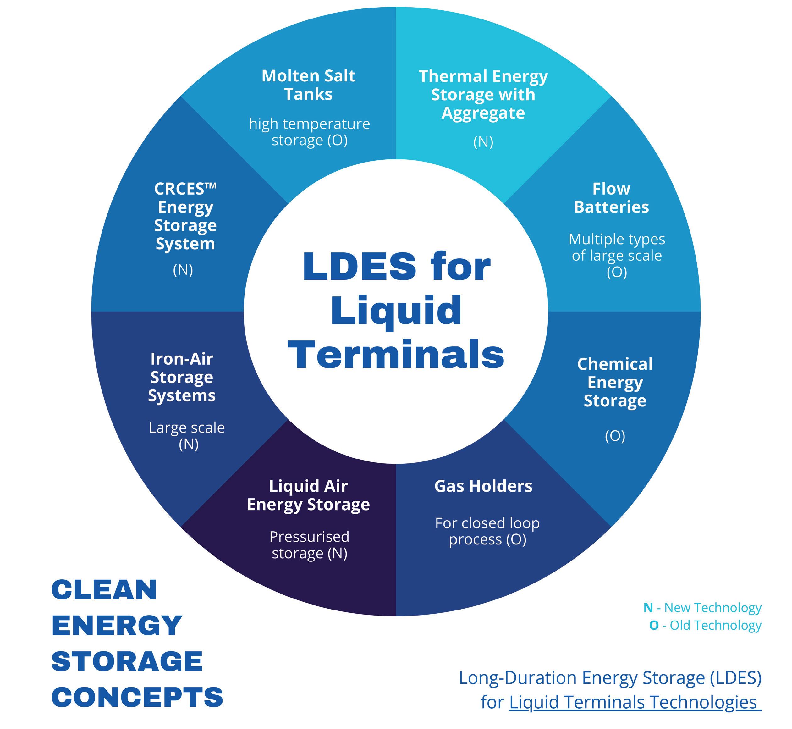
The good news is that there are many opportunities to reformulate existing hydrocarbon liquid storage terminals in order to profit from a clean energy future. The solutions incorporate emission reductions, storage of products generated through renewable efforts, optimisation, and new technologies that take advantage of existing terminal infrastructure, systems, and locations. The top eight technologies are listed in Figure 1, but the most obvious technology for liquid terminals to embrace is flow batteries, utilising bulk storage with low or no emissions, and supporting electrical energy storage (EES). Flow batteries would truly be a windfall for the tanks and terminals industry if they were economical today. However, even with an efficient flow battery solution, the equation is not complete without energy
generation. The complete solution needs to harness the terminal assets that are already in place, store energy, and at the same time capture a renewable means of power generation. The combination of these efforts paints a picture of transition success accepted by the industry and the most aggressive investors.
As a reference point for terminal storage competition, one need not look any further than lithium-ion batteries for EES. When it comes to power generation, solar and wind are the systems to beat. The liquid terminal industry can surpass the use of photovoltaic (PV) solar with batteries for reasons such as long-duration energy storage (LDES), lower EES cost, lower carbon footprint, etc.
From an investor perspective, there are plenty of selling points, but the big challenge is favourable economics. The solution lies in relatively new technology formulated to fit the liquid terminal industry. Taking advantage of the location of many terminals and their proximity to industry and power grids are key elements of success.
American Tank & Vessel Inc.’s Carbon Reduction Clean Energy Storage (CRCESTM) technology is as simple as waste heat recovery and clean bulk energy storage, and can compete with
W.T. Cutts, American Tank & Vessel Inc. (AT&V), USA, outlines the opportunities available for existing liquid storage terminals to benefit from the energy transition.
solar, wind and batteries. It offers unlimited life cycles, no cost of future battery replacement, a smaller area requirement for energy storage, and efficient LDES. The technology also has faster project timelines, and provides more local jobs compared to deploying batteries. The unit also has a lifespan of 20+ years.
The realisation of these benefits requires a commitment to working with the power community and industries in the vicinity of the existing liquid terminal. One source of energy is low-quality waste heat. Most industries have already utilised waste heat in a variety of manners but still have low-quality waste heat within their operations. Typical operations consume water, power, chemicals and land area to expel this low-quality waste heat. Technologies are available today to utilise low-quality waste heat, as well as convert tanks and systems to act as energy storage. A level one front end engineering design (FEED) study can identify the resources that can be utilised for energy acquisition, storage and distribution. Terminal companies that embrace the concept are underwriting their future by:
n Promoting a path to clean energy storage with investors.
n Adding long-term sources of revenue.
n Reducing local industries’ consumption of water.
n Expanding relationships with local industries.
n Stabilising the power grid with clean energy.
Storage of clean energy in liquid hydrocarbon terminals can be accomplished through a number of applications that incorporate technology that has been around for 30 years, and others which promote technology that is still incomplete. A review of these applications shows that many do not take advantage of the traditional hydrocarbon terminal’s assets. For applications to have a good fit, the projects need to utilise current physical assets, support deployment, leverage existing staff and systems, acquire low-cost energy, incorporate good economics, show flexibility for future transitions, and minimise the land required for new equipment.
Most clean energy storage is either burdened with incomplete technology or limited by rare materials. The CRCES technology is available for commercialisation, and has the benefit of storing energy from low-quality waste heat sources. CRCES storage technology can utilise the traditional storage tanks found in liquid terminals with modifications, while full utilisation of most tanks can be realised. Not only are the assets of the liquid terminal utilised, but the terminal’s current management systems are appropriate to operate the facilities described. Many liquid terminals operate propane facilities or blending, which is of similar complexity to operating the facility supported by CRCES. In addition, most liquid terminals are located in areas where it is easy to tie into the electrical grid, support a substation, generate behind the meter, or work through an electrical broker to sell power.
Transitioning liquid terminals to support clean energy will start with aggregating low-quality waste heat from local operators for clean energy generation, storage of energy from renewable sources for grid stabilisation, and storage of electricity from the grid to support peak shaving and/or back-up systems. Other key factors will include supporting ammonia for bunker fuel demand, and establishing a path to the hydrogen economy.
Whether the terminal is driven to have a green initiative or generate additional revenue streams, the solution is at hand.
CRCES™ supports:


• 100% US materials and labor
• Lower cost versus Li-ion batteries
• Smaller carbon footprint versus Li-ion batteries
• Long Duration Energy Storage (LDES)
John Colpo and Sudhakar Bhooramoorthy, Honeywell, discuss how an enterprise-wide approach to managing multiple oil products terminals offers a number of benefits to companies.

Oil products terminals are essential infrastructures that serve as storage and transfer hubs for petroleum products such as gasoline, diesel and jet fuel, as well as midstream and upstream products. Companies that operate multiple terminals often face the challenge of marginal economics and resistance to efficiency improvements, while also needing to ensure compliance with ever-growing health, safety and environment (HSE) regulations. One way to address these challenges is company adoption of an enterprise-wide approach that integrates all terminals into a cohesive system, rather than operating each terminal based on its individual legacy.
Today, there are fewer terminals than in previous decades. Early terminals handled logistics in localised precincts, dealt with fewer and simpler products, and pre-dated third-party access (TPA) or
Figure 1. An integrated and enterprise-wide approach provides significant value at each level of terminal operations and business processes, and covers all aspects of custody transfer, including safety, security, operational excellence and regulatory compliance. Once a holistic system is implemented, all sectors of the business will benefit.

other modes of sharing terminal and product capacity. Workflows involved several manual procedures and paper-based order and audit trails. Gate-to-gate times were typically over an hour, and tank turns were low.
Today’s terminals are fewer, but larger and more complex and costly to operate; increasingly tightly regulated for HSE protocols; and must respond to the needs of a number of stakeholders and customers. Bottom-line impact for today’s complex oil and gas terminals is driven by load-out efficiency and the ability to quickly react to market dynamics and trends in order to capture market and overdrive on tank turns.
Any lack of visibility into terminal performance adds to the day-to-day challenge of optimising the asset’s investment. The uncertainty associated with forecasting demand or identifying where the next interruption will occur – whether it is an equipment malfunction, safety incident, or out-of-spec product – can also reduce the opportunity to operate at maximum efficiency.
Constantly evolving fiscal and HSE regulations challenges terminals owners to invest capital, implement additional sub-systems, and interrupt operations. Additional challenges for terminal owners and operators include:

n A fractured view of inventory and operations across multiple terminals.
n Difficulty benchmarking performance of each terminal.
n Fewer qualified personnel due to an aged workforce set to retire.
n Geographical distribution of terminals.
n Increasing complexity needed to handle multiple-product mixes and rebranding.
n Limited collaboration across the supply chain.
Now more than ever, all categories of multi-terminal owners need to combine the operations of multiple storage terminals, applying consistent and standardised work practices across facilities to lower IT, OPEX and maintenance costs. This is true for national oil companies (NOCs), independent bulk storage operators, and all other owners.
An enterprise-wide approach provides several benefits to companies that operate multiple oil products terminals. Firstly, it allows for centralised management of all terminals, enabling better coordination of skilled activities and scarce
resources across different locations. This approach also facilitates real-time monitoring of operations, such as tank levels, temperature and pressure, which enables better decision making and reduces the risk of accidents or product loss.
Secondly, it enables the standardisation of processes and procedures across all terminals, which simplifies training, improves consistency, and enhances compliance with regulations. This standardisation also enables companies to implement best practices and continuous improvement programmes across all terminals, improving overall operational efficiency, and reducing costs and dependence on individual staff.
Thirdly, the approach enables the use of advanced technologies such as automation, artificial intelligence (AI) and predictive analytics, which can improve operational efficiency, reduce downtime, and enhance safety. These technologies can be used to optimise inventory management, predict maintenance needs, and improve energy efficiency across all terminals, providing a competitive advantage for the company.
Lastly, an enterprise-wide approach provides a holistic view of the company's performance, enabling better decision making and resource allocation. This approach allows companies to identify trends and patterns across all terminals, providing insights into areas that require improvement or investment. It also facilitates benchmarking against industry standards, enabling companies to identify areas where they can improve their competitiveness.
An enterprise-wide approach will integrate disparate inventory management, blending and loading systems to provide a complete picture of performance. It also manages the paper stream associated with operations. It is important to see how each terminal is performing relative to other sites, and to determine which terminals have spare capacity, experience bottlenecks, or have room for improvement.
It is important to employ a holistic and integrated solution across the enterprise, from the field to the control room, and up to the business level – all delivered by a single trusted supplier. Merely finding solutions for individual sub-systems will hinder the terminal from working efficiently as a whole. An integrated approach seamlessly integrates processes, assets and people, and helps turn data into actionable insight so that a business can optimise operations, predict asset performance, and reduce unplanned downtime.
Terminals can benefit from solutions that track batches of product being transported through pipelines or transferred between tanks, and provide movement monitoring so that product moved from one location can be accounted for at its destination. These solutions also offer a range of leak detection options to monitor product as it flows through pipelines.
Control and supervisory software combined with work stations can be used to automate all operations at a bulk liquid terminal, including all key monitoring and controlling functions such as product receipt, gate access control, and loading. This approach also controls the flow of information from inventory management systems, and delivers detailed process insights via an intuitive analytics dashboard.
Cloud hosting for enterprise-wide visualisation and analysis makes it possible to leverage insights found at one terminal across all terminals, which allows for more informed decision making. This solution reduces IT costs while guaranteeing high reliability, flexibility and scalability. Furthermore, faster turnaround for troubleshooting and applying fixes can be achieved, and new applications can be more easily developed, tested and deployed. Cloud-based solutions also enable business process outsourcing (BPO) of both non-core and core work functions.
Terminals have often been targets of organised crime. Cyber is the new frontier, and if not fully implemented, there can be devasting results. Fallout from a cyber incident can result in operational disruption, loss of product, non-compliance, ransom payments, or fines. An industrial-grade cybersecurity system defends the availability, reliability and safety of control systems and terminal operations to protect the entire enterprise.
Maintenance departments often have one of the largest payrolls, but they can reduce costs and increase equipment availability by switching to preventative maintenance regimes. EHM applications allow operators to build an asset-centric model of their terminal equipment that can predict outages of reliability and availability. Standard models for common equipment such as tanks and pipelines are readily available, while various terminal-specific models can also be developed.
With a precision tank monitoring solution, multiple standard tank views are available for each terminal. Personnel can be alerted by audible and visual alarms based on the inventory position in each tank.
Terminal control systems can be integrated into a wide range of servo, radar tank gauges, and associated field instruments. The gauges are tied into tank inventory systems, which perform advanced monitoring and alarming of storage inventories.
An integrated system of loading, additive and blending controllers can be utilised to optimise loading automation capabilities. Not only do controllers manage straight
loading, but they can also handle ratio and side stream blending.
Advanced systems are essential in tank and storage areas, where protection is the highest priority. Gas detection technologies can be combined with terminal control systems to ensure better situational awareness and improved response times, helping to save lives in an emergency.
Site security, including perimeter-intrusion detection, video surveillance, and access control can be integrated with the terminal control system. Security systems can be augmented with an advanced wireless network, which enables better operator efficiency and improved situational awareness.
This solution enables wireless applications such as tank gauging, overfill alarming and floating roof monitoring to be natively integrated into the control platform. A wireless solution could reduce costs by up to 50% compared to traditional wiring, while expediting project execution.
An integrated and enterprise-wide approach provides significant value at each level of terminal operations and business processes, and covers all aspects of custody transfer, including safety, security, operational excellence, and regulatory compliance. Once a holistic system is implemented, all sectors of the business will benefit.
Senior staff can accurately compare terminal performance across multiple, geographically-dispersed locations, and implement company-wide strategies to keep operations safe, quality high, and customers satisfied.
Planners can precisely determine terminal consumption and inventory distribution patterns, identify and predict product allocation for different stakeholders, monitor inventory availability at individual or multiple facilities, and plan shipments and orders from a centralised location.
Terminal managers can minimise project risk, maintain on-time production schedules, and drive business performance with scalable solutions that improve safety, efficiency and profitability.
Terminal operators can accurately monitor and maintain bay efficiency, manage terminal inventory, respond to alarms and alerts, and track and execute loading plans and shipments.
In conclusion, an enterprise-wide approach to managing multiple oil products terminals offers a number of benefits to companies, including centralised management, standardisation of processes, adoption of advanced technologies, and a holistic view of the company's performance. By adopting this strategy, companies can improve their operational efficiency, reduce costs, enhance safety, and gain a competitive advantage in the industry.
Ryan Thompson, Emerson, USA, explains how even the most experienced terminal schedulers can increase peak operational efficiency with the help of digital twin-based scheduling and optimisation software.

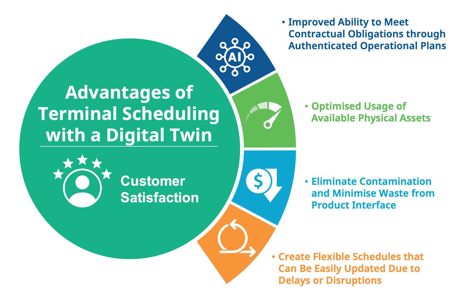
In the increasingly competitive liquid storage business, high customer satisfaction is paramount. A seemingly small delay can have multiple cascading impacts, as terminals frequently run very tight schedules to satisfy the needs of their customers. Therefore, terminal operators poised to deliver outstanding service are well-positioned to increase market share while retaining their existing customer base.
Traditionally, good service simply meant a deep bench of expert personnel who could effectively manage the tank farm with its spider webs of pipe, complex vessel schedules, and vehicle loading. Today, however, these highly skilled employees are becoming hard to find, and even harder to retain, as many of the most experienced operators are retiring. New personnel, while potentially easier to find, do not have the expansive knowledge or skill set that comes from years of experience at a specific facility.
Furthermore, even experienced human schedulers tend to be conservative in their use and operational deployment of the terminal’s physical assets. Tried-and-true asset line ups are preferred, which means that the full operational capacity of the
existing assets may remain unexplored. The ability to squeeze in one or two additional tankers a month, for example, would represent a significant increase in revenue and profit margin, but this would require running closer to constraints.
Without a paradigm shift, basic terminal operation in the future will become increasingly difficult, and possibly non-competitive against more efficiently run terminals.
Closing the inevitable skill gap while simultaneously improving customer satisfaction will require the employment of advanced technology. One of the most impactful new pieces of terminal-centric technology is digital twin-based terminal scheduling and optimisation software. Implementing scheduling software moves specialised data and esoteric scheduling processes onto a standardised and easy to use platform.
Unsurprisingly, the more complex a terminal, the more difficult it becomes to schedule the product movements, define movement interdependencies, and plan related operational activities efficiently and accurately. Operators are trying to satisfy the competing requests of multiple customers to ensure that they receive the level of service dictated by their contracts, without unexpected delays, all while avoiding unintentional transmix or contaminations.
Consider the complexity of a large multi-modal terminal facility: many dozens of tanks, scores of products, complex spaghetti webs of interconnected pipes, vessels of varying sizes whose arrival is highly dependent on weather, connections to major international pipelines, fleets of trucks moving through the terminal daily, railcar loading and storage, and inter-tank transfers. Creating a schedule for such an intricate orchestration is no simple task.
Additionally, routing a movement through the terminal’s complex of pipe headers is just the beginning, because the product portions already in those pipes must also be displaced or flushed in many cases. Each one of these displacements becomes a scheduling concern in its own right. Even after a schedule is set, circumstances can change the plan, sometimes leading to all-hands-on-deck scrambles, resulting in losses in efficiency at best, and mistakes or safety incidents at worst. Even the best prepared operators can fall victim to changes that are out of their hands. For example, operators often attempt to expedite operations by prefilling lines going to a certain jetty. But when a ship is late, operations can become complicated very quickly.
Necessity is the mother of invention, and some incredibly complex scheduling spreadsheets have been created to support this statement. Typically, scheduling spreadsheets were built by a small group of experienced users, or, in some cases, even a single expert engineer. Many terminals pin their entire operations on spreadsheets to track and schedule product movements in granular detail.
While these spreadsheets are often powerful, the inherent risk lies in the ability to maintain and adjust them when a terminal no longer has a deep bench of

expert personnel to support such bespoke solutions. If nobody else on staff understands the macros and the programming of that complex spreadsheet, the terminals quickly find themselves in a bind. Moreover, even the best, most well-supported spreadsheets are subject to human error. Improper data entry, unverified changes, and security gaps also pose a serious risk to the long-term viability of these well intended solutions. Finally, spreadsheets are simply not designed for this type of task, and are hard to create, maintain and change as a result.
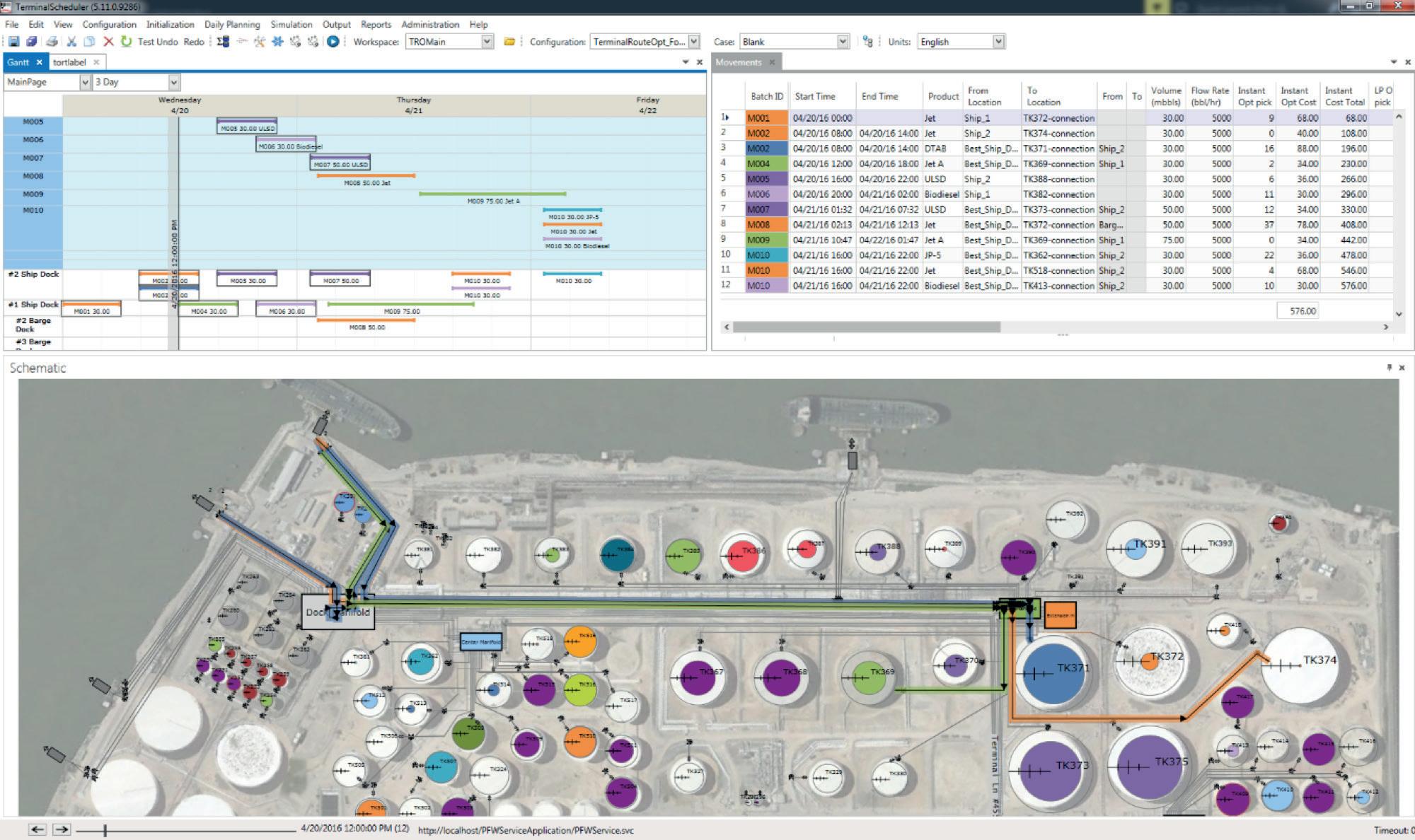
To avoid these and other problems, forward-thinking terminals are employing standardised fit-for-purpose terminal scheduling software. The leading solutions rely on simulation based on a digital twin – an exceptionally detailed replica of the facility, with digital representations of the critical physical elements needed to create an actionable schedule, including all the tanks, lines, valves, pumps, interconnections, manifolds, jetties, gantries, and more (Figure 1).

Prior to any new simulation, a few precursor activities are required:
n The period of the simulation must be set. Due to the fluid nature of terminal operations, most simulations are
run for a period of two to three days, but the length of time can vary from terminal to terminal.
n All relevant movement requests (orders or nominations for product entering, leaving or moving within the terminal, etc.) must be captured in the scheduling tool.
n The digital twin starting point needs to match the physical reality, i.e., tank levels, line fill status, equipment status, etc.
Once precursor activities are complete, the simulation can begin. The first stage is a general inventory check to ensure that the terminal will either have enough pumpable volume to go out, or will have enough ullage to bring product in. For smaller terminals with simple path routing, this may be all that is required to schedule the terminal adequately.
In more complex operations, the simulation should employ a customer-driven weighting system to determine the optimal path for movements from origins to destinations. Given that a typical terminal’s profit is heavily based on throughput, path routing cannot be left to chance.
Weight-driven optimised routing automates the process of deciding which routes products must not take, as some may be out of service, a pump on one route might not be big enough to provide the right flow rate, or some other constraint may be in place.
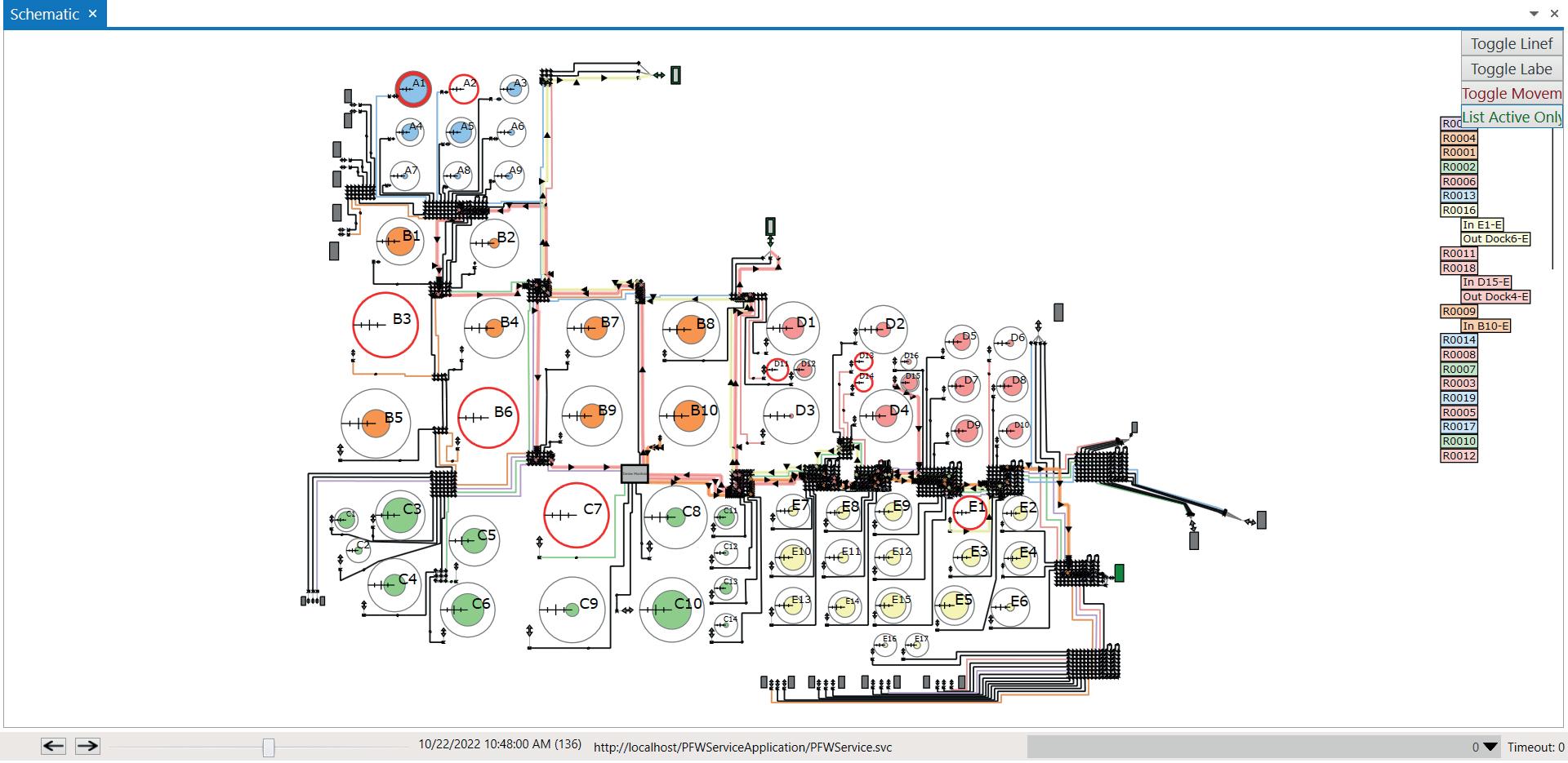
What seems like a small difference becomes a critical variable when that flow rate could mean filling a holding vessel in two days rather than three. Scheduling software tracks and incorporates all of these variables so that humans do not need to perform this complex task. This type of software application will avoid line conflicts, pipeline/tank contamination, and other scheduling complications (Figure 2).
Once complete, the simulation will either successfully pass, or produce errors. With the right software, all product movements (tank, pipeline, marine and truck/rail) can be displayed in graphical, tabular, and Gantt-style views. Using these and other tools, a passing simulation can then be approved, with the software creating a schedule and supporting line-ups.
The schedule can be sent to internal and external (connecting carrier) parties, and the line-ups can be used by operators to carry out the product movements. With the appropriate level of automation within the terminal, scheduling software can send line-ups directly to the automation systems for digital execution.
At the end of the scheduled period, or sooner if off schedule, the plan and actual movements must be reconciled in the scheduling software before a new schedule can be created.
Operators using terminal scheduling software create a schedule, including all product movement activities, for the desired length of time. The software then runs the simulation to see whether the plan is feasible. If a problem is predicted in the physical world, such as an overfilled tank, the software will return an error, letting the user know what would happen and why. Armed with that knowledge, the schedule can be easily adjusted and run through the simulation again, without the risk of real-world safety or efficiency impacts. Once the
Figure 1. Digital twins provide terminal operators with the necessary insight to deliver outstanding service, leading to more satisfied customers and increased market share.
simulation runs without error, the schedule can be published to interested parties, including external parties such as connecting pipeline operators (Figure 3).
However, whilst having a perfect plan is the ideal scenario, what happens when a ship reports that it will be coming in eight hours early or late? It does not matter how good a model looks or how detailed the schedule is if it cannot easily accommodate minor or major changes. With scheduling software, an operator can easily modify the ship movement and re-run the simulation to identify new conflicts, see how any changes will cascade down the line, and identify which elements – such as truck and rail loads – may need to be rescheduled. Schedule upsets will still need to be remedied, but scheduling software makes it far faster and easier to get the terminal back on track.
Flexibility in handling real-world situations also benefits the planning stage. Terminal schedulers can use the power of digital twin technology to test an infinite number of scheduling ‘what-ifs’ against their operations strategies. What if a supplying refinery ramps up production? What if a tank or line segment needs to go out of operation for service? With a few adjustments, the simulation can report back the outcome of the change in a matter of minutes. The options to tweak and optimise the schedule are truly endless.
In today’s competitive landscape, companies are running leaner, and terminals are no exception. The challenges of reduced staff are compounded by a general decline in overall experience due to the retirement of more experienced workers. Terminal scheduling software can help ease the burden on these small teams while simultaneously closing the knowledge gap, making it easier for less experienced operators to perform their work, and with more confidence.
Traditionally, setting a terminal schedule could easily take hundreds of clicks in a spreadsheet or other software program, each one essential to getting the process right. Data entry throughout the process leaves room for errors, as critical information is manually transcribed from multiple source systems.
Today’s terminal scheduling software solutions automate most of the process. Operators can typically complete a schedule in far fewer clicks, cutting time out of the scheduling
process. Additionally, scheduling software can connect directly to external systems such as enterprise resource planning packages and order-to-cash software. Data from these systems can be automatically pushed down to the scheduling software, simplifying the process of defining and creating movements, while eliminating the risk of human error in data entry from source systems.
The personnel benefits of automated scheduling go well beyond simple time savings. Partial automation and support of the asset line up validation lends a higher level of certainty to that process. The software can also provide close to real-time capabilities to monitor and verify that the schedule is being executed as planned.
Time saved leads to opportunities to work on other high-value tasks, such as reviewing data trends for additional efficiency gains.
Adopting terminal scheduling software will provide immediate benefits to the day-to-day operations of the facility, and it is also a critical step in securing future success.
Traditional scheduling methods only provide the terminal’s owners with general knowledge and inexact certainty as to what was in each pipe, and what the exact state of the terminal is at any particular time. In contrast, a digital twin can exactly identify the state and content of all assets and volumes in the terminal.
Companies in every industry are realising the massive value of their data, and are looking to a more connected and data-centric future where granular field-level data is aggregated to make key business decisions – both for individual facilities and for the enterprise. Analytics can be applied to this data, with the insights used to find trends in deltas between the terminal’s schedule and actual results.
For example, a diverging trend may only be seen on one segment of pipe within the terminal. It could be that a valve is not opening completely, causing a reduction in actual vs expected flow rate. Quickly identifying and resolving such issues is critical for a fully optimised terminal operation.
Today’s sophisticated terminal customers expect more than a functioning terminal; they want an efficient terminal that provides insights that help them to manage and optimise their own businesses. Terminal scheduling software can provide these capabilities through the easy and automated transfer of data, forecasting at different levels – such as inventory and individual tank levels – and notifications of delays as early as possible, whether due to product movement disruptions or equipment downtime. Operators are finding that scheduling software not only helps them operate more efficiently and effectively, but also gives their personnel more time to focus on facility safety, gain competitive advantage through customer service, and achieve top performance among their competitors.
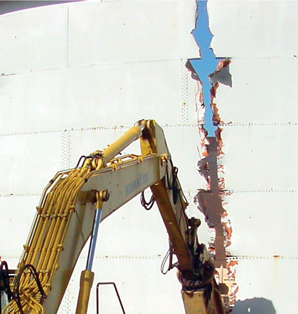
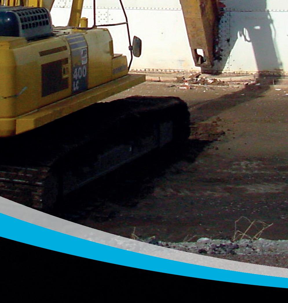
Oil and gas terminal operators are looking for the safest, most cost-effective and ecologically-friendly tank cleaning service to maintain their storage tanks. There are several key requirements when carrying out internal cleaning of tanks. In addition to removing hazardous products for safe disposal and ensuring that the risk to personnel during tank inspection procedures is reduced, it is also important to ensure that there is no cross-contamination of product, should the tank usage change.
Sediment and sludge residue take up considerable volume in the bottom of oil tanks, limiting their storage and affecting the quality of the products held within. Contaminants can corrode the floor and inner walls of the tank, and the residue can add stress to the integrity of the structure of the tank, as the weight of the sludge and sediment is sporadically dispersed across the tank floor. This can also cause damage to floating roofs and prevent them from providing a tight seal.
Terminal operators have the primary responsibility of ensuring operational and process safety, and the personal health of the operating staff. Safety guidelines have mandated periodic inspections and operating standards, with the purpose of protecting people and the environment against industrial accidents. These are devised to help prevent accidents from happening, to reduce the frequency and severity of incidents, and to mitigate their effects – should they occur.
Incidents can have major consequences on the environment and workers’ health, and can lead to oil terminal facilities paying dearly in terms of repairs, loss of share value, cost of closure, remediation, and claims.

Tank cleaning methods that focus on safety procedures, cleaning effectiveness, time and money reduction, and ecological preservation have all been highlighted by oil majors in recent years. Additionally, the desire to cut maintenance costs while still improving safety has shifted the focus to automated systems. This involves no man entry that can replace an entire human crew and can run on continuous shifts without downtime. This solution also allows oil majors to get their asset back up and running up to 60% faster than if conventional cleaning processes were being used.
The gauntlet has been thrown down to tank cleaning companies to employ the latest health and safety standards and environmental guidelines while planning, managing and administering a faster, smarter, no man entry service.
Oil industry bodies are signalling an end to confined space entry by 2025. In response,
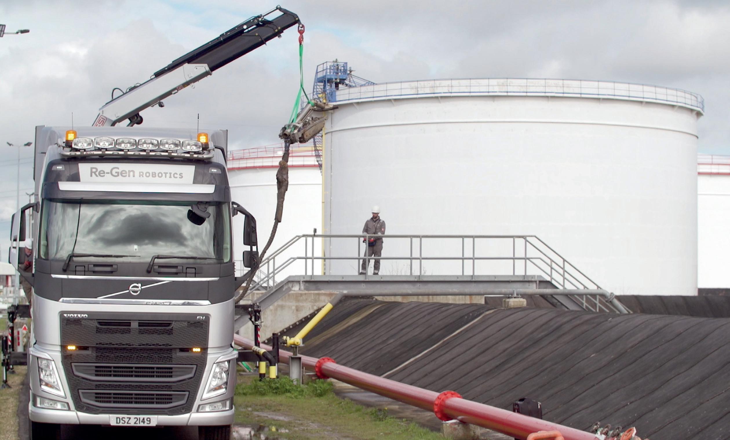
Aidan Doherty, Re-Gen Robotics, UK, details how terminal operators can improve safety and cut maintenance costs by applying smart tank cleaning solutions.
no man entry robotic tank cleaning systems can eliminate the risk to human safety in hazardous environments and confined spaces. Re-Gen Robotics has developed a Zone 0, Ex certified, remote controlled cleaning system. The cleaning systems were created to tackle crude oil, black oil, white oil and distillate tanks, and feature closed looped cleaning circuits and a highly-efficient hydrocarbon recovery system to protect the environment.
When conducting no man entry robotic tank cleaning, it is important to begin by compiling detailed information on the tank(s) to be cleaned, including size, type, location, contents, volume, and nature of material contained within. A formal assessment of the risks associated with the cleaning task should then be performed, and the operational history of the tank, with information on the products that have been stored within the tank, established.
A proposed cleaning methodology should then be presented to the clients, who should be given the opportunity to ask any questions regarding equipment and processes. At this stage, a timeline and next steps can be completed, and a sample proposal on timings and costs of the proposed tank clean should be provided. This will be indicative if exact details of the volume of the tank material is unknown; otherwise, a final proposal can be prepared if all elements are up to date.
This is followed by a site visit to assess the tank(s) and meet the team to gain a comprehensive understanding of the scope of work. Once all of the details have been specified, a final proposal outlining method, timeframe and cost can be
submitted, and the detailed responsibilities of everyone involved throughout all stages of the cleaning and reinstatement process are agreed. The highest levels of health and safety and environmental and quality procedures must be observed at all times.
Re-Gen Robotics’ self-contained system is comprised of robotics, vacuum, jetting and cranage, so there is no capital outlay for terminal operators. The clean begins with the mobilisation and installation of equipment, according to a thorough installation plan that has been approved by the tank owner.
The ADR tanker is stationed alongside the tank bund, and the self-contained cranage system lifts the robot over the bund wall and positions it in front of the tank manhole. This is particularly useful for tank farms and terminals situated in remote locations.
The certified robotic operator manages all aspects of the tank clean from a dedicated, air-conditioned control room through a series of ATEX cameras and gas monitoring equipment. This ensures that every clean, no matter what category of tank, is uncomplicated, as the operation is remotely controlled with permanent visual connection.
The tank does not need to be gas-free to enter when using no man entry robots. As a result, all equipment installed on the robot is anti-explosive and hydraulically propelled to remove any danger of fire or explosion. Paperwork and permits are also reduced, and there is no requirement for capital outlay or spading of tanks.
The tank cleaning robotic system has been designed to fit through a standard 600 mm manway, using externally fitted hydraulic ramps, and begins the process of extracting sludge from the internals of the tank. Each robot is fitted with an auger system capable of breaking down heavy sludge without using water, meaning that it produces less waste. Sludge and sediment are extracted by the ADR-certified jet vac tanker, which has a vacuum capacity of 4800 cm3/hr, using high-pressure, low flow jetting systems, and the powerful vacuum.
The system has an offset suction head to allow for precise cleaning underneath heating coils, and the low-profile tool can access underneath pipes and remove waste from below the heating coils. It can also operate offset on the left, right, and straight-ahead positions. This tool can decrease tank cleaning time by approximately 10 – 12%.
The self-contained system simplifies the entire tank cleaning process. Productivity is enhanced, and tanks are brought into operation more quickly.
Robotic tank cleaning systems can be set up by two workers in two hours, which saves time in comparison to that taken for human crews to prepare to enter a tank.
Clients can also be provided with a recording of the tank cleaning operation, and the truck telemetry system provides real-time information to clients so that they can monitor energy consumption and waste generation.
Re-Gen Robotics was commissioned to clean three 15 m tanks at Vermilion Energy’s gas terminal, which refines and purifies gas from a gas field on the west coast of Ireland.
The first tank scheduled to be cleaned contained methanol, and the remaining tanks contained condensate,
a low-density mixture of hydrocarbon liquids present as gaseous components in raw natural gas.
The tanks were resin lined and contained a large amount of internal furniture including aluminium legs, skim arms and floating pontoons. The entry manholes were raised slightly higher than standard tanks, and there was manifold piping situated on the ground around the tanks’ exteriors.
Upon initial inspection, it was discerned that a portable raised platform would be required to allow the robot to pass freely over the exterior pipework, in order to meet the manhole entry ramp. The platform was supplied by the client and was also used for the other tank cleans.
It was also noted that the height of the tank was considerably lower than most tanks and that it would therefore be necessary to restrict the height of the telescopic camera bracket attached to the tank cleaning robot. Rubber stoppers were fitted around the ATEX camera that would restrict the height of the camera bracket with a length of chain.
The ADR tanker was stationed 10 m from the tanks and the robotic equipment was craned into position. Scaffolding
equipment was not required as Re-Gen Robotics supplied the crane system to lift the robot into position. Full magnetic tracks were fitted to the robot in order to maintain the integrity of the resin lined floor.
At no time during the entire cleaning process was there a requirement for human presence in the confined space. The operator remained in the Zone 1 control unit where they could monitor activity through a series of ATEX cameras and gas monitoring equipment fixed to the robot.
The unique features of the large robot made it ideal for cleaning the storage tanks. The combination of specially designed 3500 psi jetting water nozzles, powered by a high-pressure low flow pump, were critical to the cleaning process.

Sludge was then extracted by the ADR certified jet/vac tanker, and by using a fully-contained waste removal and a 360˚ cleaning process, the waste material was transported offsite with an ADR tanker and safely treated in an authorised, licensed facility.
The entire tank cleaning operation was recorded on CCTV by the ATEX cameras, and was made available to the client upon completion of the works. All files are date and time stamped to ensure that the process is traceable for auditing purposes.
On completion of each vessel cleaning, final readings were confirmed, the tanks were handed back to the client, and the robots were demobilised.
By engaging Re-Gen Robotics’ team, who meticulously planned the project, the tanks were cleaned faster than anticipated (reducing tank shutdown duration by half).
Re-Gen Robotics has maintained an exceptional work record throughout every tank cleaning contract. To date, all jobs tendered have been accepted and completed on time and to budget.
The speed and efficiency of the tank cleans exceeded the client's expectations, by finishing ahead of schedule and by significantly reducing the amount of tank downtime.
Demand for autonomous tank cleaning has soared in recent years. In 2020, a global survey was commissioned by Re-Gen Robotics that asked engineers, managers and senior executives with responsibility for hazardous area operations their preferred option for cleaning oil terminal tanks. It also asked those more generally involved in the safe installation and operation of the plant and equipment within potentially explosive atmospheres to disclose their main industry concerns. An overwhelming 86% of survey respondents expressed a preference for 100% no man entry tank cleaning at their terminal. Their main concerns were risk of death or injury (76%), followed by an environmental incident (61%) leading to their tanks being out of commission for longer than scheduled. The survey confirmed that the desire to take workers out of tanks has always existed but up until then, there was no tried and trusted method of doing so. Autonomous robots, drones and AI for tank maintenance and cleaning have entered a growth super cycle, and the companies that can translate new intelligence into working technology at pace, and constantly improve their products and service, will grow aggressively in this sector.
Edoardo Marangoni, Alberto
Daniel
and Alessandro
Srl, Italy, analyse the genesis of robotic technologies for tank cleaning, and consider various options that are available to the market.
The removal of sediment inside storage tanks is a necessary maintenance activity to preserve the integrity of storage tanks and ensure operational continuity of the facilities in which they are applied. The presence of liquid or solid sediments can compromise the productivity and capacity of the tanks. Furthermore, in the event that the material contained inside the tank is changed, each tank needs to be completely cleaned. Historically, these maintenance activities have always been carried out through

the use of specialised workers sent inside the tanks. However, this approach poses a high risk to workers who, despite being equipped with approved personal protective equipment (PPE), have to operat e in hazardous environments. In addition, the various regulations on safety methods and procedures for working in high-risk spaces require that a large number of personnel are employed to ensure that each operator has at least one rescuer in case of illness or accident.
Two alternative no man entry technologies are available: recirculation and separation systems, and systems using remotely-controlled robots.
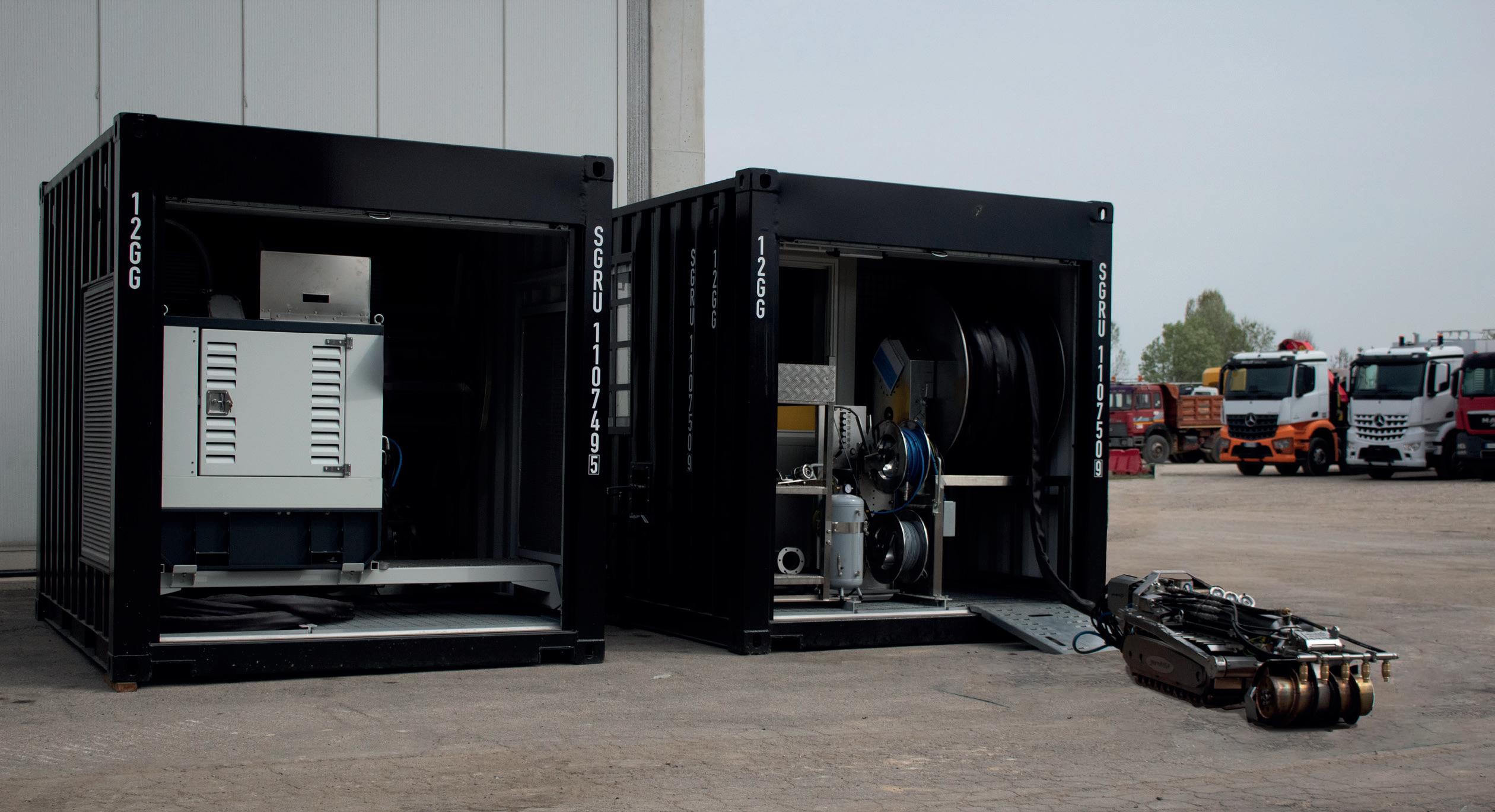
‘Closed-loop’ systems for the removal of sediment through continuous recirculation of sludge inside tanks have been in operation for many years. They use different processing steps guaranteed by different modules: a suction module, separation module, recirculation module, and skimming module. These are usually set up inside containers. Thanks to these processing steps, tank cleaning takes place through a continuous recirculation process: once the material has been fluidised and sucked in, it undergoes a mechanical separation process to separate the solid part from the liquid part and, subsequently, to separate the water from the hydrocarbons. The latter are then recirculated back into the tank. This process, which involves an initial inertisation of the environment to avoid explosion risks, aims to ensure effective cleaning while recovering as much material as possible, which is then returned to the plant.
Remote operated vehicles (ROVs) are alternative solutions that allow for more punctual and faster cleaning. The ROVs enter the tanks and are connected to a remote vacuum unit (vacuum truck).

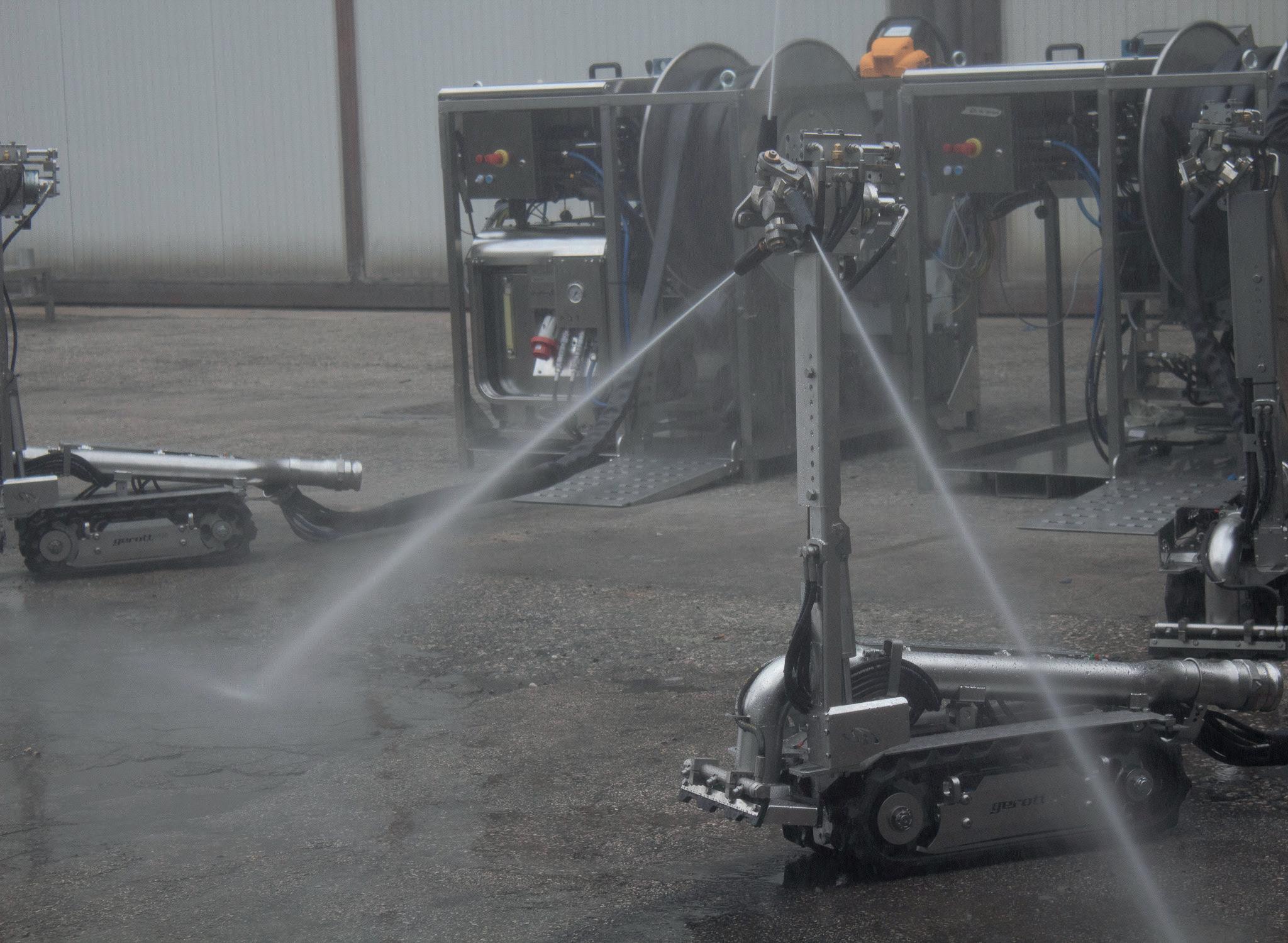
If one had to point to a date that kickstarted the development of no man entry robotic solutions, it is certainly 2003. This year saw the birth of the ATEX directive regulating products and processes in hazardous areas. This made it possible to have the same regulations for all EU countries, consistent with the principle of free movement of goods, thus leading to an increasingly receptive market. The ATEX certification not only covers electrical components, but also encompasses all other mechanical parts of the machine. This has led to a considerable engineering evolution and greater product safety. The certification – alongside increased awareness of worker safety throughout the early part of the decade – provided an impetus to the sector. In industrial plants and refineries, there was an increasing focus on procedures, prohibitions, methodologies and precautions to keep people out of the 'line of fire'. The synergy between ATEX certification and safety has therefore created increased demand for robots from contractors and asset owners. However, technological development has had to come to terms with unavoidable operational constraints. The most important of these is the manhole, which, as standard, has a diameter of 600 mm. This means that every functional aspect and moving part of the machine (hydraulic arms, front attachments, umbilical connections, etc) must be built to pass through the tank access opening.
The two large families of no man entry technologies leave a third option open: intrinsically safe robots with an onboard pump. From a technological point of view, this fits between robot technologies and recirculation systems. The solution is easy to set up, avoids tank
Strategically located petroleum bulk storage facility. e only deep water platform (64’ operating dra ) on the U.S. East Coast
• 20 storage tanks 80 miles East of New York Harbor.


• The only deep-water loading/unloading platform on the U.S East Coast.
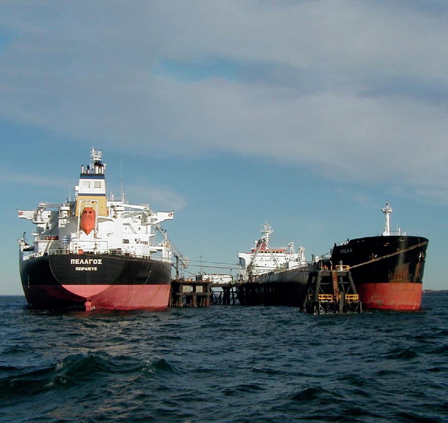
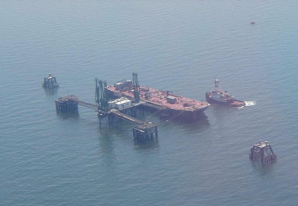
• Total Storage Capacity of 5 Million Barrels.
• Easy reloading for distributi on of product to U.S., Canada and Europe.
United Riverhead Terminal, Inc. (631) 284-2010
blanketing, and the removal of material takes place continuously, without the need to depend on the emptying times of the vacuum truck tank. The fact that the pump is onboard means that the robot can work without needing to be connected to an external suction unit (vacuum truck).
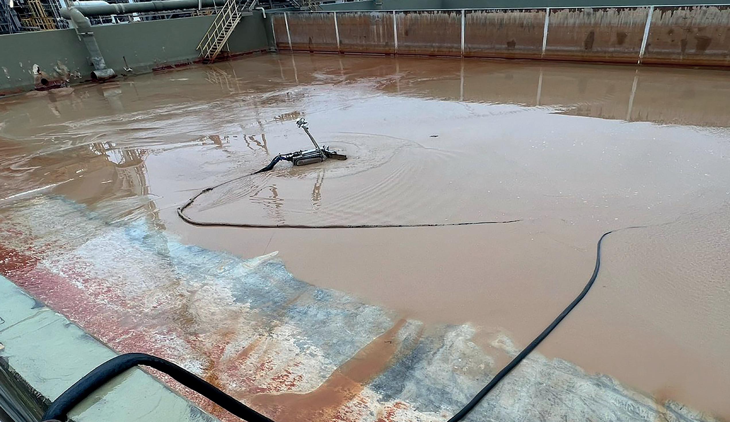
The type of pump can vary according to operational requirements, fields of application, and the material that needs to be pumped. Centrifugal and dredge pump models, for example, are applied for cleaning water purification tanks and cooling towers. Other models, such as lobe and progressive cavity pumps, are suitable for sludge removal and are therefore applicable for tank cleaning. Obviously, each pumping system – lobe, progressive cavity or other – has structural limitations that make it more or less suitable for the physical and chemical characteristics of the materials to be pumped (viscosity, presence of sand, solids, moisture, etc). These solutions offer the possibility for a narrower 2.5 in. suction hose as opposed to a 4 in. (and possibly even 6 in.) suction hose typical of a robot that is attached to a vacuum truck. The constraint for these applications is the 24 in. dia. manhole. However, the possibility of fitting a narrower suction hose than necessary (2.5 in. instead of 4 in.) allows for less heavy, more agile, and more manoeuvrable machines.
In terms of productivity and performance, the technologies behave differently. For example, vacuum systems allow the passage of solids that can be as wide as the diameter of the suction hose. In contrast, lobe pumps (for instance) allow the passage of non-compressible solids of up to 4 mm. Furthermore, pump systems work with a high productivity in the case of white oil and a medium productivity in the case of black oil, while vacuum systems guarantee a lower hourly productivity for both black oil and white oil (largely due the time it takes to empty the truck tank). Furthermore, in terms of environmental footprint, the consumption of diesel and energy are different. On the one hand, there is the truck, which is an energy-consuming vehicle. On the other hand,
there is a system that works autonomously – without a vacuum truck – and continuously. One system consumes more energy but for less time, while the other system consumes less energy but for longer time intervals. Another element to be considered is the consumption of solvents or water used to fluidise the material to be removed. In the case of black oil sediments, in particular, the high compactness of the material forces it to be diluted to a greater or lesser extent, depending on the case. With a vacuum truck, pneumatic transport is carried out (i.e. the material is dragged through the pipe by the speed of the air until the maximum vacuum limit of 0.8 bar is not reached). With viscous fluids, the material tends to stick and stop in the pipeline, so vacuum technology needs to transform the slurry into liquid in order to be transferred. However, this runs into the obvious problem of waste generation. Even for robots with an onboard pump, there are available solutions that can mount material recirculation systems that, by diverting the flow of the pump delivery, allow the sucked material to be remixed with the least possible volume of water or solvents, in order to decrease the solids content until the compound is pumpable.
Finally, there is the issue of sensors, which clearly distinguishes between solutions with an onboard pump and those connected to a vacuum truck, and which intersects with the requirements of the ATEX standards. If it is possible to certify all elements for ATEX Zone 0 with a robot connected to the vacuum, this certification is very problematic for the onboard pump. For example, if a progressive cavity pump sucks in material that is too dry or runs on vacuum for too long, there is a risk of overheating that must be taken into account when working inside storage tanks. This implies that the robot with an onboard pump must include electrical sensors (temperature and pressure) that are capable of monitoring pump operation and any anomalies in real time. While this aspect is fundamental in terms of safety and compliance with ATEX directives, it can also open up some interesting opportunities in terms of developing a telemetry system that, in addition to providing data on possible anomalies, can also provide elements for analysing performance, productivity data, and activity reports, for example.
The impetus provided by the ATEX directive and safety regulations has certainly opened up the field to important technological developments. The various options can basically be grouped into three categories: vacuum robots, robots with an onboard pump, and recirculation solutions. All of these options have advantages and disadvantages, and can fulfil different functions in tank cleaning. However, the goal is common: to offer contractors and asset owners a system that eliminates the need for workers to enter tanks.
Danny Constantinis, EM&I Group, Malta, discusses some innovative solutions to the challenge of safe tank inspection.
Assuring the condition and integrity of the bottom plating of floating hydrocarbon production tanks such as the cargo oil tanks of an FPSO on station, in operation, remains one of the significant challenges for those engaged in their safe operation. Self-evidently, a
defect leading to a failure is potentially catastrophic. Resolving this challenge has obvious benefits for the integrity of other forms of offshore and production tanks such as the gas storage tanks of a floating LNG (FLNG) facility, FSRU or LNG tanks; notwithstanding initiatives by

classification societies to extend LNG carrier inspection intervals for those vessels located near shore, where sloshing forces are minimal.
Despite strenuous efforts to improve safety, offshore fatalities continue, as testified by numerous safety reports. One such report, recently commissioned by EM&I, sought to better understand and mitigate the risk that its staff faced offshore, especially when working in dangerous confined spaces. 1 In this report, entitled ‘Safety in Confined Spaces with Reference to Floating Production Storage and Offloading Units (FPSOs) and other Marine Vessels’, Professor Andy Woods of the University of Cambridge stressed the inherent dangers of confined space entry (CSE) and working at height.

The report empirically quantified the risk and the associated monetary cost of a fatality before drawing an important observation “that the current level of risk of a fatality is higher than industry guidelines would wish and that the consequences of these incidents although relatively rare are very substantial in terms of both the fatality and also collateral impacts of lost production and corporate reputation.”
The bottom line is that injuries and fatalities are still occurring in the industry. This is preventable in many ways, and its continuation is simply unacceptable at every level.
The industry recognises the need to improve safety. As an example, the work of the global FPSO Research Forum
and the Hull Inspection Techniques and Strategy (HITS) joint industry project (JIP) provides an important illustration of what can be done, and signposts a future in which owners, operators, classification societies, service providers and academic bodies collaborate to seek technical solutions to offshore challenges. To date, their work has successfully focused on limiting dependence on diving operations and reducing the need for people to enter dangerous confined spaces. There are a number of important examples of this success.
In addition to special optical cameras for general, close and visual inspection, the NoMan Plus® system embodies laser measurement to detect hull distortion and to measure steel. Beyond Visual Line of Sight (BVLOS) tethered drones equipped with ultrasonic thickness (UT) probes enable close visual inspections and complement the laser thickness measurements. This is all delivered remotely, in an approved, safe and carbon-reducing way.
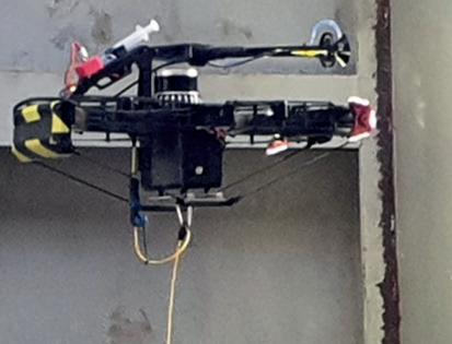
EM&I’s LIMPET® system is an intrinsically safe diverless method for blanking sea chests without the use of divers, using an ‘intelligent’ motorised wire guided blanking plate. The solution is delivered remotely, and without resorting to a diving spread and dive support vessel, thus saving on valuable headcount and on carbon emissions as a consequence of the reduced footprint due to lower headcount. All of this can be done without impacting production operations.
The third remaining challenge is to investigate how to safely examine and identify defects on the bottom plating of cargo oil tanks (COTs), without manned entry. One hopes for perfect conditions: the tank being out of operation, clean, warmed for manned entry, dry, free of external marine growth, gas-free, and with safe and simple access for technicians. In this perfect situation, some 1.2 million ultrasonic readings over a typical surface area of 3000 m 2 might be necessary to satisfy the requirements of the regulators. However, extended out-of-service periods for COTs are commercially unpopular, and it is rare to achieve perfect conditions for inspection, with operators frequently reluctant to clean the oil residue from the tanks because of the financial cost. As such, it may be possible to use external non-intrusive techniques to provide an equivalent inspection.
There are a range of innovative solutions either on the market and being adapted to this requirement, or that exist but have not yet been tested under stringent representative conditions, such as the following:
n Magnetic flux leakage (MFL) can identify the presence of corrosion, pitting, and wall loss. This is a

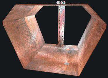
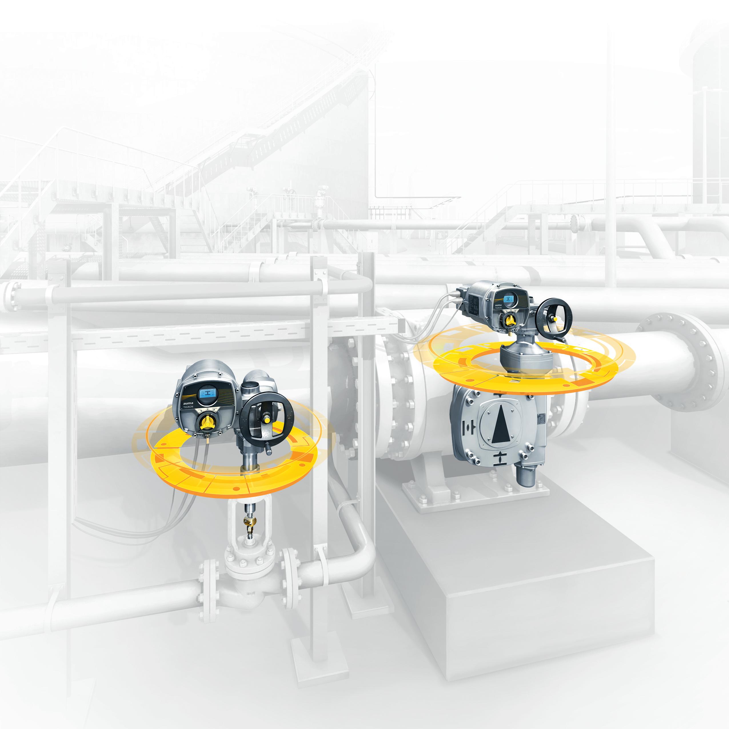
portable and effective technique for detecting subsurface cracks, though the sensor is limited to approximately 15 mm wall thickness, where bottom plating is usually 20 – 25 mm thick.
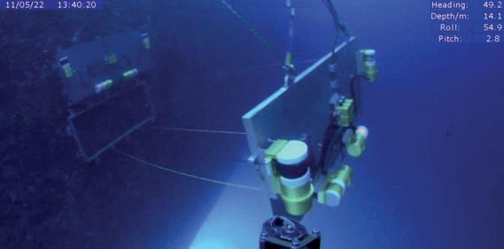
n Pulsed eddy current (PEC) is an established technique and provides a relative volumetric analysis. It is very effective under certain conditions.
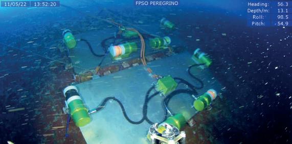
n Electro magnetic acoustic transducers (EMAT) can inspect through coatings and are generally not affected by pollutants, oxidation, or roughness. EMAT transducers are easy to control and deploy.
n Acoustic resonance technology (ART) is a patented, ultra-wideband acoustic inspection technology.
n Magnetic eddy current (MEC) is a variation of eddy current testing that allows for the identification of flaws in the volume of thick ferritic steel components.
EM&I has witnessed two of these promising sensor technologies under representative conditions: ART and MEC. The results are very encouraging, although more work is required to fully validate the application for bottom plate inspection in the field.
For both sensor technologies, a trial, sponsored by the FPSO Research Forum and the HITS JIP, was established at EM&I’s Technology Development Centre using a representative and approved test piece that permitted inspection on both internal and external surfaces of a steel plate. Trial defects included pitting, grooves, acid damage, and cracks of different dimensions. The trial included wet and dry scenarios, and simulated marine growth.
ART uses a transducer that shoots a broadband (multiple-frequency) sound signal towards a target. The signal duration is sufficiently long enough to generate oscillations in the target. As the oscillating target continues to be struck by the sound signal, the resonance greatly amplifies the oscillations. The resonating frequencies (frequency domain) are characteristic of the thickness and material of the target, and are measured. The trial outcomes were judged a success: the smallest defect, a 20 mm dia. pit on a clean plate, was readily found and quantified, although further evaluation will be necessary to fully evaluate the performance of the ART sensor.
MEC testing finds flaws in the volume of thick ferritic steel components. The eddy currents penetrate deeper into the material, and potentially other types of defects are picked up as a result. Wherever a wall cross section is reduced due to corrosion or other material flaws, the magnetic flux lines will concentrate. This leads to higher magnetisation and lower permeability. The change in permeability changes the impedance of the coil and thus creates a signal. The trial outcomes were positive, and both surface and subsurface defects were identified in 20 mm thick plating when the sensitivity of the MEC equipment was calibrated against this thickness.
Remote inspection technology is all about getting the right sensor to the right place at the right time. The choice of sensor crucially depends on what anomalies you might expect to find when you get there; the choice of vehicle to get the sensor is of course important, but the choice of sensor remains paramount.
Notwithstanding this advice, access for remote inspection sensors is a challenge, and so the choice of deployment vehicle is important: sensors may be deployed through the narrowest of available openings; they must be capable of operating under demanding electromagnetic constraints; must cope with the payload weight; and must have the power to be capable of operating for extended periods of time. Both the ART and MEC sensor trials demonstrated that a range of deployment options were viable, including the use of crawlers.
Innovative companies are hurrying to deliver exciting ‘delivery systems’ to the market. This is unfinished business at present, but innovative and effective solutions to the vexed challenge of remote bottom plate inspection are just around the corner.
Fuel bunkering refers to the transfer of fuel for use by ships. It is a critical aspect of the shipping industry, as vessels require a reliable source of fuel to operate efficiently and safely. However, the bunkering process does not solely involve marine vessels. Storage terminals also play an important role in the overall process.
At the initial stages of the bunkering supply chain, raw product (e.g., crude oil) is refined into marine fuel and stored in large tanks at refineries or storage terminals. When required, fuel is transferred to an intermediary vessel, such as a bunkering barge or tanker. Fuel can be loaded onto the vessel either through a dedicated pipeline or via a truck, depending on the infrastructure and equipment available at the terminal. In some cases, ships or bunkering barges can be fuelled directly from the storage facility where the fuel is held if they are close to a port or shore (known as shore-to-ship bunkering). Ships usually sail to a dedicated bunkering port (such as Singapore or Rotterdam, the Netherlands) to perform bunkering, and this can also be performed offshore at sea between two vessels (ship-to-ship). Regardless of the method used, storage terminals play a key role in ensuring a reliable source of fuel for bunkering purposes.

Accurate measurement is therefore critical in every step of the bunkering process due to the enormous volume and value of fluids stored in bulk storage tanks worldwide. In 2022, for example, the volume of bunker sales in the Port of Singapore alone reached 47.9 million t. This is just one port, and the amount and value of fluids involved on a global scale are significant. Accurate measurement of fluid quantity plays a key role in maintaining trust amongst all stakeholders. For both inventory control and bunkering purposes, measurement of fluid quantity in storage tanks has traditionally been carried out through tank gauging.
Accurate tank gauging is a critical component of the bunkering process, serving several purposes in both storage terminals and ship-to-ship bunkering. In storage terminals, tank gauging is necessary for assessing tank contents, managing tank inventory, and controlling the tank farm. Precise levels of inventory are essential to ascertain whether demands for a particular product can be fulfilled. Similarly, tank gauging (sometimes referred to as tank sounding) is still commonly used for measuring fuel
Tariq Boussouara, TÜV SÜD National Engineering Laboratory, explains why the use of mass flow meters for fuel bunkering is likely to become increasingly widespread in the future.Figure 1. Bunkering a tanker container ship.
quantity transferred during bunkering operations. An important aspect of tank gauging is determining liquid level.
Manual level gauging is measurement using a graduated dip-tape or dipstick, and this approach is still commonly used. It can be a challenging technique to use during periods of adverse weather, hours of darkness, or when staff are using personal protective equipment (PPE), and it has a higher uncertainty than automatic methods.
Float and tape level gauges use a large heavy tape with a float connected via a cable to a balance weight. This is combined with a scale and pointer along the tank shell, indicating the level. The weighted float and indicator are connected to the counterweight by separate cords, each cord running over a pair of pulleys. When the float is half immersed, everything is balanced. Rising liquid levels lift the float up, the counterweight moves down, and the indicator keeps pace with the float. Falling liquid levels cause the weighted float to pull the counterweight up. This method is inexpensive but can be prone to errors due to corrosion and mechanical issues.
With servo type level gauges, the float is replaced with a small displacer suspended by a flexible measuring wire. The displacer is raised and lowered using an electrical servo motor. A weighing system continuously measures the weight and buoyancy of the displacer and controls the servo system. Typical uncertainties in level using this method are considerably lower than float gauges.
Radar level gauges involve a ‘downward looking’ measurement system installed on a tank roof. They use a time-of-flight method to measure the depth. In this method, radar impulses from an antenna reflect off the liquid surface and are received again by the radar system. These signals can be sent through the air (‘non-contact radar’) or guided using a probe towards the process fluid (‘guided wave radar’). The distance to the liquid surface is proportional to the travel time of the impulse. Radar gauges can be more accurate than other methods and have no moving parts. However, they can be expensive to install.
Storage terminals often employ level sensors that are connected to a control system in order to continuously monitor the fuel level in the tank. On the other hand, tank gauging (or tank sounding) on board marine vessels tends to make use of portable equipment and is typically more manual in nature. Regardless of the application, the selection of a tank gauging method will impact the overall uncertainty of the process.
Uncertainty is a range of numbers either side of a measurement result within which the true value is expected to lie (within a given confidence). In the oil and gas industry, the confidence level is typically 95%. Accounting for all sources of uncertainty in tank volume or mass measurement is important, particularly when custody transfer of fluids is taking place. Level measurement is only one aspect of the tank gauging process. There are other sources of uncertainty that contribute significantly to the volume or mass of fluid being measured. These need to be combined with the uncertainty in level in order to provide an overall uncertainty. Some of these sources include (but are not limited to) the following:
The uncertainty due to tank deformation is caused primarily by the weight of the product against the side of the tank wall, which can cause the walls to bow. In addition, the capacity of the tank will drift over time. This necessitates recalibration of the tank every 5 – 10 years, usually. This process creates a set of tank capacity tables (often called strapping tables) that are used to give an accurate value of the volume between two levels, and there are uncertainties in these strapping tables that must be accounted for.
To accurately measure the mass or the standard volume of the oil, a precise value of the density of the fluid must be used, which is dependent on temperature. It is common for warmer fluids (less dense) to rise to the top of tanks. To minimise this effect, mixing devices are installed in the tanks at different heights. However, this can still contribute a significant source of uncertainty in the mass or standard volume.

The capacity of the tank may change due to thermal expansion. The impact of thermal expansion on the tank shell can vary and is dependent on the temperature and type of product being stored.
The wind blowing on the surface of the tank can also cause temporary changes in the level measurement, and if the wind is strong enough this can make the uncertainty significant.
The sources of uncertainty in tank gauging are similar between storage terminals and ships, however the challenges of measuring and accounting for these sources of uncertainty can be greater on marine vessels. Tanks on ships are subject to constant movement and vibration, which can make it more difficult to obtain accurate measurement of liquid level. In addition to this, these tanks are typically smaller and less stable than those in storage terminals, which can further increase the potential for errors in measurement. However, smaller tanks tend to limit the effects of temperature stratification and thermal expansion of the fluid compared to larger storage tanks.
Another factor that can affect the uncertainty of tank gauging is the condition of the tank. In ship-to-ship bunkering, the tanks on the vessels may be subject to more wear and tear due to the vessel's motion and exposure to the elements, which may necessitate more frequent recalibration of the tank capacity.
Tank gauging remains a crucial tool for inventory management in storage terminals. However, the challenges associated with performing tank gauging on ships have led to the use of mass flow meters for bunkering applications.


As previously mentioned, tank gauging has conventionally been utilised for custody transfer in bunkering applications. Nevertheless, there is now a shift toward the use of mass flow meters for measuring the quantity of fluid transferred.
Mass flow meters can offer higher accuracy than traditional tank gauging systems (particularly for small batch transfers), which can be affected by factors previously discussed such as temperature, pressure, and tank geometry. Mass flow meters measure the flow of fuel directly, which eliminates the need to measure tank volume and account for the factors that can affect the accuracy of tank gauging. They can also reduce the time and effort required for tank gauging and calibration, which can help to reduce downtime and maintenance costs.
Although they offer benefits, there are some key considerations associated with the use of mass flow meters. For instance, the high initial installation cost is a significant barrier for many operators. Furthermore, the meters require regular maintenance and calibration in an accredited flow laboratory such as the TÜV SÜD National Engineering Laboratory to ensure accurate measurement. Despite these challenges, the use of mass flow meters for bunkering is expected to increase.
Fuel bunkering is a critical process in the shipping industry that requires accurate measurement of fuel quantities to ensure a safe and efficient transfer, and to maintain trust between all parties involved. Storage terminals play a crucial role in this process, often at the earliest stages of the bunkering supply chain. Although traditional tank gauging methods have been effective and remain essential for operational and inventory control in storage terminals, the emergence of mass flow meters for bunkering offers several advantages. These include improved accuracy, increased transparency, and reduced uncertainty.
The shipping industry is continuously evolving, and the use of mass flow meters for bunkering is likely to become increasingly widespread in the future. In fact, mass flow meters are already mandatory for bunkering applications in the world's largest bunkering port, Singapore, with Rotterdam also planning to follow suit. It is common for disputes to arise during the bunkering process, and the adoption of mass flow meters is expected to address this issue. For product transfers at storage terminals, mass flow meters can also provide a secondary verification for existing tank gauging systems.
As bunkering uncertainty continues to reduce further down the measurement chain, and the industry moves towards using mass flow meters, storage terminals must invest in equipment and maintenance to keep uncertainty levels low and meet the demands of the changing industry.
Ideally arranged, the proper amount of Jet Mixers produces a three-dimensional flow that mixes the entire contents without creating a rotating motion in the tank. Delivering high efficiency, operational safety, resistance to fouling and little wear & tear thanks to its simple and robust construction Download

In light of current world events leading to a period of irregularity in the global LNG market, it is much more likely that receiving terminals will obtain supplies from different sources around the world at present – as opposed to their usual singular source. With this irregularity of supply comes the potential for a diversity of LNG compositions to be stored in each tank. This combining of sources leads to a higher likelihood of stratification occurring and, with that, an increased risk of a damaging rollover event.
Due to the costly and potentially fatal nature of rollover events, it is vital that plants have the solutions necessary to accurately predict these events and minimise their impact.
A rollover event can result in a rapid and significant release of vapour, causing overpressure and physical failure of the storage tank. When more than one LNG composition is stored in a tank, the LNG products do not easily mix due to LNG having a very low viscosity. The different compositions form layers in the tank, like oil and vinegar in a French salad dressing, with the denser material at the bottom of the tank and the lighter layer on top. When such stratification occurs, a barrier is formed that prevents the movement of heat from the base of the tank to the liquid surface. The heat becomes trapped in the bottom layer, causing its temperature to gradually rise and, as a consequence, expand – it will become less dense.
If the density of the lower layer of the product changes so that it is the same as that of the upper layers, rollover can occur. The trapped heat causes the liquid layers to evaporate more quickly, resulting in the release of excessive vapour and subsequent overpressure. If the tank cannot withstand the increase in pressure, it may physically fail, causing it to rupture and release harmful and potentially flammable gases and vapours into the environment.
The first documented incident of this kind occurred in 1971 at the La Spezia receiving terminal in Italy. The LNG cargo delivered by ship was held in port for about a month. During this waiting period at sea, the product increasingly heated up in the Italian sun, causing its density to change. Some of the methane boiled off, which meant that the LNG now had a high ethane content and a higher boiling point. When the ship was finally able to deliver its cargo, the tank was bottom filled for 13 hours, which
created stratification as the lighter and colder heel of the tank was displaced upward by the ship’s cargo. Whilst there was boil-off, it did not appear to be excessive, and for the first 18 hours the tank's boil-off rate and pressure were within normal limits. Unexpectedly, the boil-off rate then increased to 120 times the normal rate for a duration of around 90 minutes.
In this instance, the vapours were safely expelled through the safety valves and vents, and the tank roof only sustained minor damage. Whilst the outcome could have been worse, the incident was serious enough to prompt widespread research into the causes and effects of rollover events, with the La Spezia incident being the basis for future modelling and protocols.
Fundamental to models based on the La Spezia research are the heat and mass transfer coefficients, which are used to estimate how much heat and mass can travel up through each layer of product, and therefore at what point density equalisation occurs. These coefficients are determined by the design of the tank and the type of LNG being stored. In 2011 and 2012, MHT Technology/Endress+Hauser, in collaboration with the University of Sheffield (UK), developed the ‘Inverse Model’, which estimates the heat and mass transfer coefficients using real-time level, temperature and density information provided by an LTD gauge. While this model is easier for site operators to use, the necessary calculations for the model to work require a detailed initial composition of the LNG products being stored. Since the composition must be manually entered by site managers, this would mean that operators estimate the composition as a ‘best guess’ upon reception of LNG.
As rollover events are time-sensitive, the most accurate forecast possible is essential to determine the timing of the event as precisely as possible. This requires accurate composition information. To improve this, the LNG Automatic Composition feature has been developed for the Tankvision LMS software, which provides a more accurate and less user-dependent forecasting model.

Added in 2020, the Automatic LNG Composition selection feature allows for detailed composition information to be obtained autonomously from LTD gauges and gas chromatographs. When taking the composition from an LTD gauge, the composition is determined using the
Dandee Bacani, Endress+Hauser, Japan, examines how efficient instrumentation can help predict rollover events and minimise potential damage.
‘known source’ method. This method requires site managers to first enter a list of probable compositions based on the sources that they expect to receive. Before running the rollover forecast calculations, the software selects the composition whose temperature and density are closest to that recorded by the LTD gauge as the initial composition. Alternatively, if sites are using a gas chromatograph on the export line (these devices measure the composition of the discharged gas to ensure it is within specification), this data can then be used as the initial composition for the forecast. Thanks to this feature, rollover forecasts can now be performed automatically, without the need for operator intervention after the initial configuration.
Since the composition of the LNG products is expected to change over time due to the mixing of the layers and preferential
boil-off of the lighter species from the upper layer, the model used by the software will continuously ‘tune’ the input composition to ensure that it is accurate and up-to-date, providing the most accurate forecast possible. This means that operator involvement is kept to a minimum. When updates to the necessary information are required, such as when a new source is imported into the terminal, the information for the new gas fields can be easily entered into Tankvision LMS through the implementation of a web user interface. This web interface also provides easy feedback on the current status of the storage tank. In addition, operators can visualise whether a tank is homogenous or stratified, and whether or not rollover is predicted.
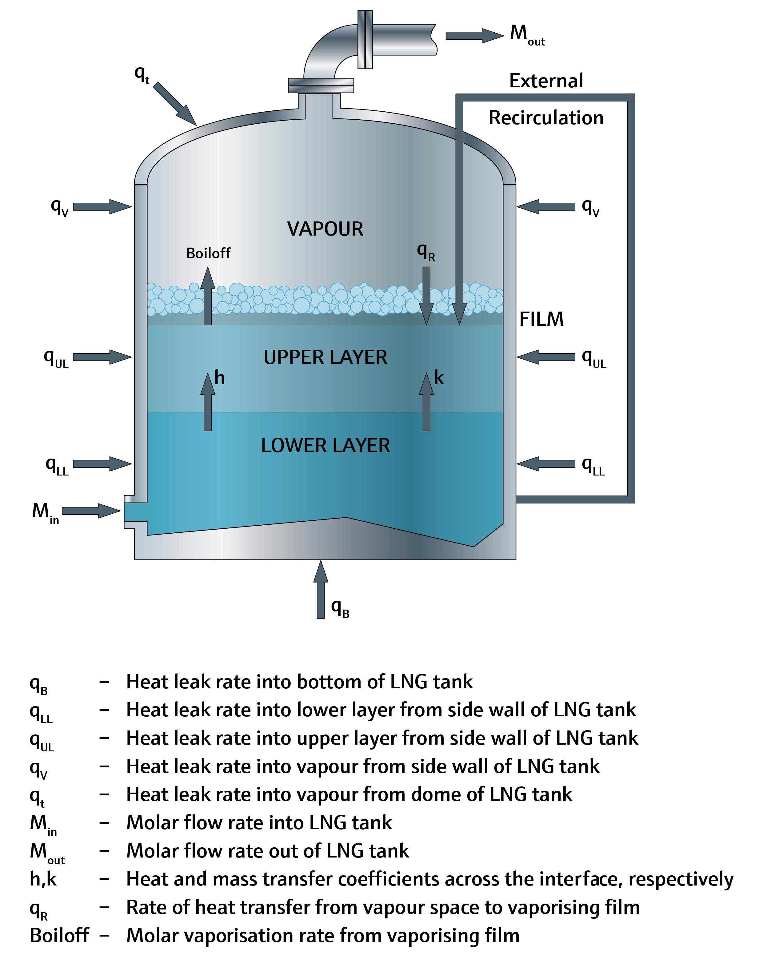
In December 2022, MHT Technology/Endress+Hauser's Tankvision LMS software was deployed at a customer site in Virginia, US. The deployment took place as part of an upgrade of the existing software and included the scheduled rollover feature as well as the new associated automatic composition facility.
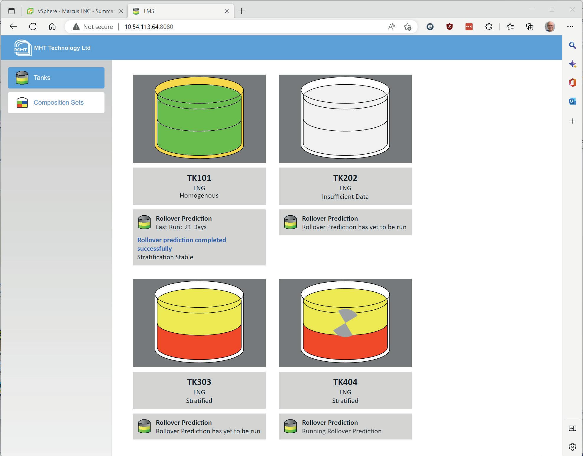
The plant operators were already monitoring the stratification of their LNG storage tank, but decided to upgrade their software following a training programme focusing on LNG rollover. The peak shaving plant in Virginia stores excess natural gas during the summer months when demand is low, to feed back to the national grid in the winter. In the changeover from exporting to importing gas, the tank contents can weather, leaving a dense heel in the tank, and setting up the conditions for stratification and eventual rollover.
The automation starts with a scheduled profile of the tank. The LTD gauge is sent a command by Tankvision LMS to complete a full profile of the tank contents. The second stage of the analysis takes place after the profile is completed; a rollover calculation takes the last two profiles and analyses them for stratification. If both are stratified, the system is then able to compute the rate of change between the two, and estimate from that the time taken for the stratification to break down and result in a rollover event.
Alarms are used to alert operators to the tanks’ status and keep them informed of tank stratification and any forecasted rollover events. In addition to this, the simplified user interface graphically summarises the status of the tanks. Fully automated rollover monitoring helps to ensure safer operations than before. As the pipeline system is currently being upgraded to provide a reliable and abundant supply of natural gas for the region's current and future needs, the investment in safety and rollover prediction is also an investment in the long-term supply of the surrounding area.
Effective instrumentation is vital to a plant’s safe and efficient operation. The new LNG Automatic Composition feature provides plant managers with an easy-to-use and accurate method for predicting rollover, offering users all of the information and tools that they need in order to properly monitor and predict rollover events. By being clearly and accurately informed, they can take the necessary steps to contain and manage the event, preventing product loss, site and equipment damage, and potential injuries to personnel.
Many years ago, oil and chemical operators began adopting a systematic approach to process safety and risk management, guided by two international functional safety standards: IEC 61508 ‘Functional safety of Electrical/Electronic/Programmable Electronic Safety-related Systems’ and IEC 61511 ‘Functional safety - Safety Instrumented Systems for the Process Industry Sector.’
Both of these standards use a safety life cycle approach consisting of an ‘analysis’ phase where hazards are identified, including likelihood and consequences. This is then followed by a ‘design and implementation’ phase, where example calculations of performance and risk reduction that have been achieved are quantified. Finally, the process folds into an ‘operation and maintenance’ phase, where the performance of the plant-wide system is measured against predetermined safety integrity levels and reliability standards.
LNG facilities are adopting similar functional safety principles, especially in the area of leak detection. With demand for LNG
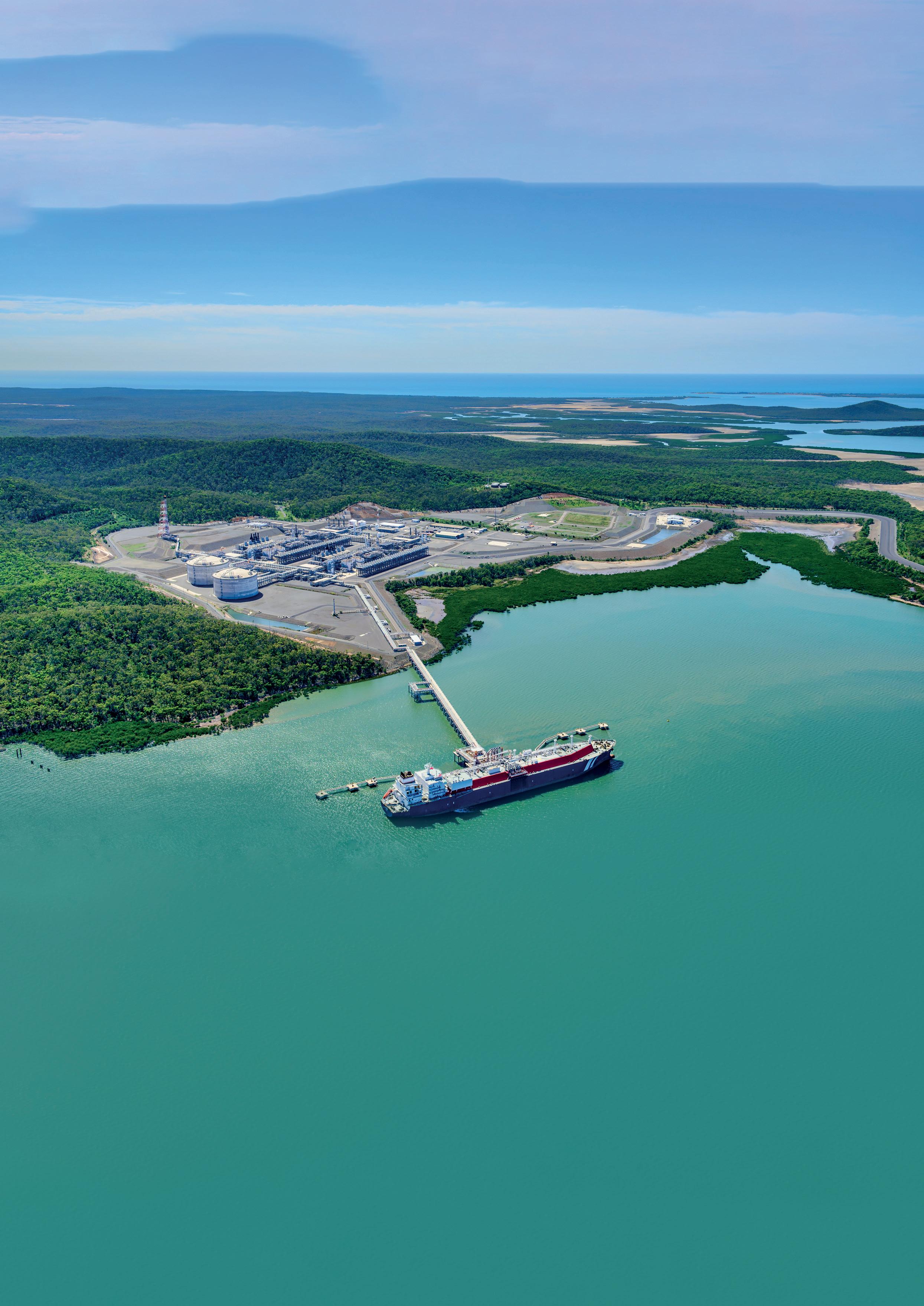
growing, operators need a scalable way of safely processing and storing product, detecting a loss of containment, deploying fire and gas systems reliably where needed, and providing interlocking devices for de-energising equipment. In fact, operators require a whole gamut of preventative and mitigative measures for the protection of personnel, plants and the community.
Process safety experts have learned many lessons from analysing past accidents in the LNG sector. Two experts, whose work will be cited in this article, have studied no fewer than five events over a 50 year period between 1966 and 2016, recording key details and lessons that point to specific considerations, such as designing around safety instrumented systems (SIS).
At the spring meeting of the American Institute of Chemical Engineers (AIChE) in April 2020 (16th Global Congress on Process Safety), a paper entitled ‘Application of Safety Instrumented
Julian Yeo, United Electric Controls, USA, considers how it is possible to learn lessons from past incidents in the LNG sector to create a systematic approach towards leak detection.
Systems in Liquefied Natural Gas (LNG) Processes’ was presented by two functional safety experts from exida –Denise Chastain-Knight and Patrick O’Brien.1 They began their presentation by examining five incidents at LNG plants that resulted in multiple fatalities and enormous destruction. Here are the key takeaways, quoting directly from the paper:
n Leaking LNG will create ice or hydrate as it vaporises. Final element valves must be specified to function in the presence of these solids.
n On loss of containment, LNG will vaporise, and has the potential to spread over a large area, where it can encounter an ignition source. The SIS must rapidly detect the leak and perform system isolation to reduce the size of the release.
n Process operations, such as filling, must have redundant systems that act to halt operations before loss of containment occurs. Processed conditions can change rapidly, so field elements must have a rapid response time.
n Once loss of containment occurs, it is desirable to stop equipment, such as compressors that add energy to the
system. This equipment must be stopped quickly and reliably while minimising the potential for false trips.
From observable lessons to the work of standards committees, a growing body of knowledge is available that informs functional safety approaches for LNG facilities including the identification and improvement of safety instrumented functions (SIFs), and the design of SISs to address those functions.
Prescriptive and other worldwide standards relating to LNG design, construction, equipment and processes support a systematic approach expressed in the IEC’s functional safety standards. For example, EN 1473 – the European standard for ‘Installation and Equipment for Liquefied Natural Gas - Design of Onshore Installations’ references both IEC 61508 and IEC 6151 standards. Accordingly, these references constitute a requirement of the EN standard in whole or in part. The same linking paragraphs and references are stated in EN 50495 ‘Safety Devices Required for the Safe Functioning of Equipment with Respect to Explosion Risks.’
The US standard NFPA 59A ‘Production, Storage, and Handling of Liquefied Natural Gas (LNG)’ empowers alternative approaches to addressing the safety of processes and equipment, as long as these designs are approved by the authority that has jurisdiction. The standard includes an annex with explanatory material including risk criteria, hazard identification, risk assessment and risk management. This applies to the plant as a whole, and to individual systems, subsystems, and components.
Manufacturers of discrete equipment are contributing to the overall effort by designing certified products and safety systems in compliance with IEC 61508, often referred to as the umbrella standard from which derivative, sector-functional safety standards have emerged.
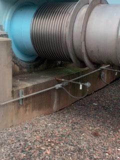
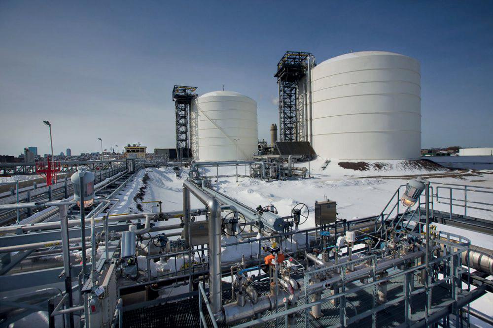
In their paper, Chastain-Knight and O’Brien touch on some key principles and considerations, including developing a functional safety management plan (FSMP). Many LNG projects have multiple vendors with different safety approaches and unique products. According to these experts, this can lead to an inconsistent risk profile for the facility. LNG operators must first align technology providers early in the design phase. Missing this step can lead to “costly redesign, start-up delays and unmitigated risk exposure.”1
Secondly, it is recommended that the LNG operator methodically selects the appropriate sensors and final elements for the application and the environment, including meeting the defined safety integrity level (SIL) for a given function. Functional safety standards equate the SIL with how much risk reduction is expected and achieved. The user should build a safety case, calculating probability of failure (PFD) in an example SIF in order to establish SIL capability, and consider other limits including fault tolerance, architectural constraints, proof testing and system restoration requirements. Sensors and final elements are no longer an arbitrary selection, but systematically evaluated to fulfil the required SIL.

On the supply side, manufacturers of sensors, logic solvers and final elements used in LNG facilities should invest in product certification to bolster their reliability claims and help quantify the level of risk reduction achieved. Product certification is a clear way of proving that equipment satisfies the applicable functional safety standards, making it easier for the LNG operator to evaluate as part of the FSMP and equipment selection. An example of such a certification database is exida’s Safety/Security Automation Equipment List (SAEL), a repository of certification documents, functional safety assessments (FSAs) and information on a range of certified automation products.2 The certificates on this database include failure-in-time (FIT) data, which designers use to calculate PFD for both low demand and high demand safety functions.
LNG facilities are equipped with temperature sensors to detect leaks in wells and spillways within the dike containment area. A sudden drop in temperature detected by the temperature sensor indicates a loss of containment. This SIF is designed to initiate a plant-wide fire and gas (F&G) system to lay a blanket of foam in containment areas. In this hazard scenario, the SIF or SIFs would also de-energise equipment (e.g. compressors or pumps) so that no trace of LNG is pumped out of the containment area into neighbouring municipal septic tank systems, as well as to minimise the likelihood of a vapour cloud finding an ignition source.
Sometimes, during the colder winter months, these temperature sensors can become prone to failure due to snow and ice build-up (Figure 1). Often, these are standalone temperature sensors that require a wire run to a remote distributed control system (DCS) or programmable logic controller (PLC) (Figure 2). As part of a plant improvement effort, one particular LNG operator decided to adopt a systematic approach towards LNG tank safety by implementing safety loops and deploying SIL-certified integrated devices as an upgrade to many of its instruments, including temperature sensors.
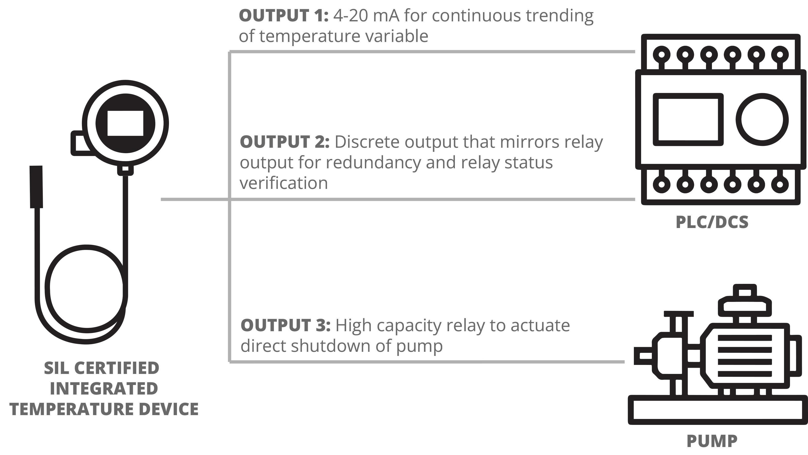
By deploying an integrated SIL-certified sensor-transmitter-switch (e.g. United Electric Control’s One Series Safety Transmitter, Figure 3), the LNG operator now has three safety variable outputs to detect an LNG leak and execute a safety action: a 4 – 20 mA signal, a programmable high-capacity solid state relay, and a discrete output. This type of standalone SIS is a cost-efficient upgrade compared to an individual temperature sensor, and offers more flexibility in terms of functions and data reporting, while minimising sensor failures.
If there is an LNG leak, the sensor-transmitter-switch detects the change in temperature and initiates a direct emergency shutdown of the sump pump while simultaneously signalling the DCS to fill the dike containment area with foam to prevent the ignition of fugitive natural gas. By acting directly to shut down pumps, the LNG operator achieves faster system response times and greater risk reduction. A voting mechanism of these safety devices could be employed to maximise availability.
Examples of these solutions can be found within the SAEL. In the first example, the discrete temperature sensor is a Type A (electromechanical) device with no logic or automatic self-diagnostics. In the example of the solution upgrade, the integrated device is considered a Type B (programmable electronic) product by virtue of its programmable electronic design and its self-diagnostics. Failure rate data is compiled and categorised differently for each of these Type A and B products.
The steady adoption of functional safety standards, beginning with the oil and gas industry, has influenced the process and energy sectors – including the growing LNG industry. Driving this adoption are lessons learned from prior incidents, together with expert analysis that informs a systematic approach to functional safety design for LNG facilities. Long-standing normative and prescriptive standards support this growing functional safety science aided by Certified Functional Safety Experts (CFSEs). Takeaways for LNG operators include having an FSMP for aligning safety philosophies across multiple vendors, and evaluating sensors and final elements based on factors such as its PFD. Equipment manufacturers should consider SIL certification to substantiate reliability claims. Public repositories such as exida’s SAEL offer operators access to functional safety assessments and FIT data for certified equipment such as sensors, logic solvers and final elements. Leak detection for LNG facilities can now be approached systematically instead of arbitrarily.
The author would like to thank Chan Reis, freelance technical writer.
1. CHASTAIN-KNIGHT, D., and O’BRIEN, P., 'Application of Safety Instrumented Systems in Liquefied Natural Gas (LNG) Processes', exida, (April 2020), https://www.exida.com/Resources/Whitepapers/application-of-safetyinstrumented-systems-in-liquified-natural-gas-lng-pro
2. ‘The Safety/Security Automation Equipment List’, exida, https://www.exida.com/sael
Ewart Cox, Assentech, UK, outlines the importance of accurately measuring and reporting on the volume of leakage from tank breather valves.
Storage tank and biogas digester operators are facing a conundrum as they seek to comply with new legislation such as the Industrial Emissions Directive. Tank breather valves enable storage tanks to ‘breathe’ during liquid level or temperature changes, such as heat from the sun or the cooling effect of a rain shower. They are also used for emergency relief as a consequence of rapid heating during a tank farm fire, or as the last layer of pressure protection on a biogas digester.
However, tank breather valves have been increasingly recognised as a principal source of fugitive emissions of volatile organic compounds (VOCs) that drive global warming and can damage the health of people, wildlife and plants. The Technical University of Denmark recently named these valves as key drivers of emissions from biogas storage. Biogas is
60% methane – a principal greenhouse gas that governments across the globe are aiming to reduce.
Innovative technology that can measure and report on the volume of leakage from tank breather valves at a chosen operating pressure relative to the set point is available. Prior to the invention of Assentech's Vent-Less test benches – which automatically measure a valve’s functional efficiency according to international standards API 2000 and ISO 28300 – this was only possible by estimation.
In addition to comparing a valve’s function according to the standards, the Vent-Less device can also measure and document the volume leak rate at a predetermined pressure defined as a percentage of the set point.
The set point for a breather valve is defined in the standards as the point at which an increase in flow does not

correspond with an increase in retained pressure. As such, a breather valve is not closed at the set point, but is actually partially open. Many tank farm operators do not understand this. The test protocol does include a test for the leak rate, which is vital for defining the valve set point. The volume leak rate is defined in a table that defines three flow increments: 0.5, 5 and 20 ft3/hr, depending on the valves' connection size ranging from 2 in. to over 20 in. In order to pass the test, the valve must retain at least 75% of its set point pressure.
Unlike safety relief valves that operate at pressures of over 0.5 barg, a breather valve set point is often in the region of 10 – 20 mbarg – the equivalent pressure of a party balloon. Surprisingly, this small amount of pressure creates immense forces measured in tonnes on large-volume, fixed roof storage tanks that can hold many thousands of tonnes of volatile liquid.
It is important to note that with tank breather valves, tiny increments in pressure will correspond to huge flow rates once the valve has been opened.
Testing tank breather valves is more challenging than other types of pressure relief devices because they operate proportionally rather than in a simple open/closed snap action way. Proportional operation means that the valve starts to open between 75 – 90% of the valve set point and continues to open between 10 – 100% overpressure (over set point).
The criteria for a leak rate pass according to standards involves the valve retaining more than 75% of the set point at a
specified flow according to Table 10 in the standard. For example, a DN100 (4 in.) valve set to 20 mbarg will need to retain more than 15 mbarg with a fixed flow of 0.5 ft3/hr that is 14 l of air.
This involves observing the retained pressure under the valve while controlling the air feed rate. The set point is found when an increase in air flow does not correspond with an increase in retained pressure. At this point, the valve is open and controlling pressure in the tank or digester.
Guidance on valve testing has been a part of the American Petroleum Institute (API) guidelines since the early 1960s, which is a long time before environmental concerns were part of daily discourse. It was originally a technical bulletin, and was finally introduced into the main body of API 2000 in 2008 when it was co-branded with ISO 28300. This test has a critical safety function and is a minimum requirement for each individual valve manufactured prior to dispatch to the customer.
The intention of the test is to confirm that the valve has been assembled correctly and works as intended. There have been cases where the pressure/vacuum valves have been assembled by the manufacturer or service provider incorrectly, leading to structural damage to the tank. The pressure/vacuum pallets are interchangeable in most designs. If the operating pressure is higher than vacuum, in most cases an incorrectly assembled valve will not open at the desired setting when product is pumped out, or when the tank cools.
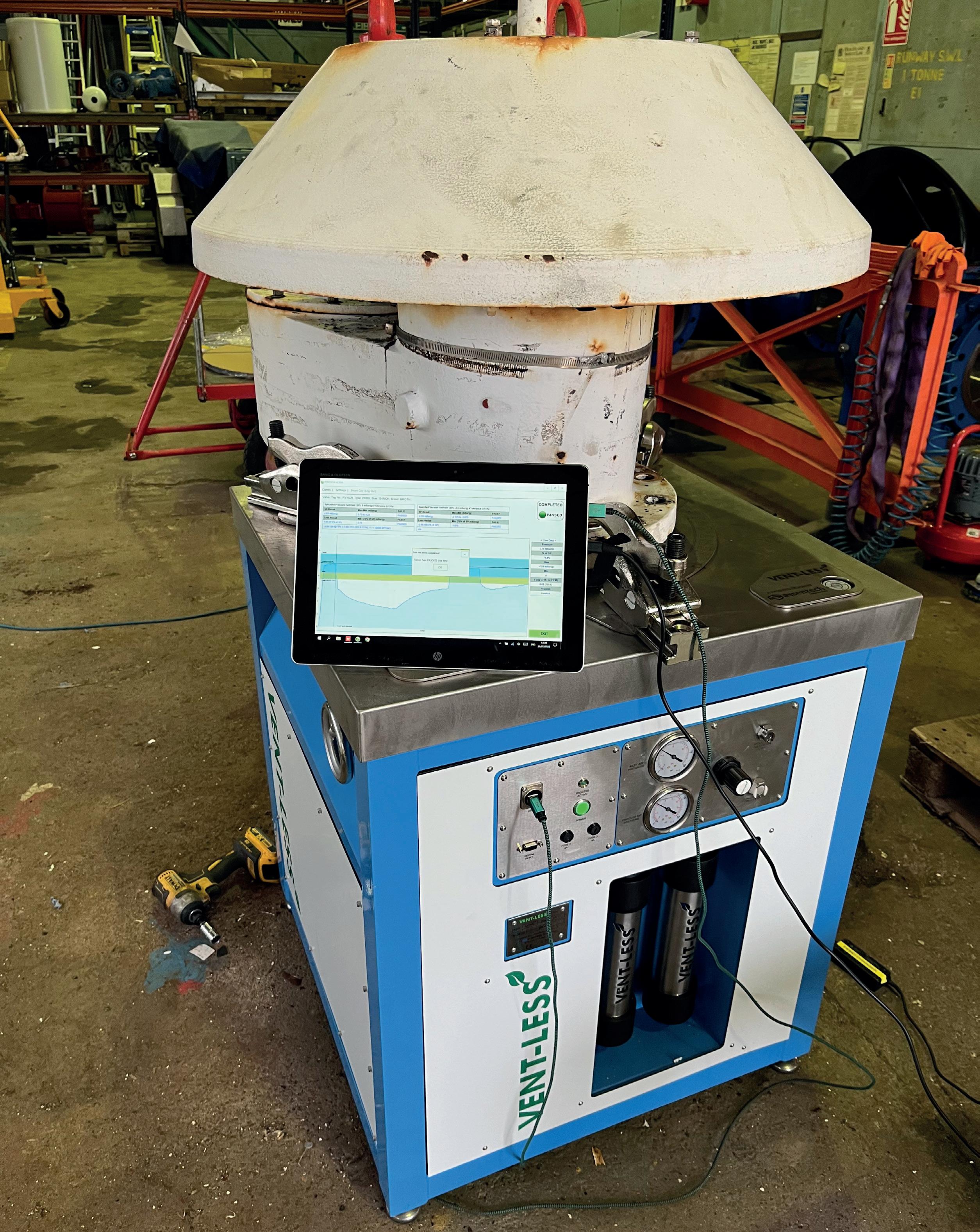
It is a shocking indictment of the oil and gas industry that the majority of valve manufacturers still do not test and certify production valves prior to shipment, in accordance with standards. This is a consequence of cost cutting in order to drive prices down to improve competitiveness and speed up production. Until the introduction of automatic valve testing, an individual valve test could take up to 20 minutes and could result in a failure on leakage. Failed valve tests require that the valve be inspected, reworked and tested again. Thankfully, this procedure now only takes 2 – 3 minutes using computerised testing.
Unfortunately, a large percentage of buyers decide to buy valves based on price alone, and are not aware of the risk that they are taking with their highly-valuable assets. A typical storage tank with associated process piping, control system and pumps often exceeds £1 million, but all too often the untested, cheapest available valves are purchased to protect them. Valve manufacturers often hide lack of testing behind certificates of conformance, but a deep dig and a request for individual valve test certificates will reveal that none are available.
Breather valves are operated by weights, springs, or a pilot mechanism. Approximately 90% of installed valves are weight-loaded, operating below 50 mbarg. It is possible to calculate the setting of a valve by measuring the seat ring diameter and weighing the pallet assembly. This technique is used as a starting point in the assembly of a valve. It is
highly reliant on pallet sealing integrity, which is why this method is not defined in standards due to the many variables that can affect a valve’s efficiency, such as pallet design, sealing integrity of the casing, and cover seals.
Breather valve design is guided by international standards that have evolved since the 1960s. Industry experts meet regularly to discuss experiences in tank storage and how the standards can be improved to support both manufacturers and users.
API 2000 was last revised as Edition 7 in 2014, and is currently being reviewed for Edition 8. The technology has not evolved very quickly over the decades, with the majority of manufacturers copying simple, early designs to keep pricing low. For many manufacturers, this leaves little cash or incentive for research and development.
However, there are rays of light from within the industry. A handful of manufacturers have adhered diligently to the standards and only manufacture quality, compliant devices that are designed to offer years of reliable service, and perform as intended. These manufacturers innovate and develop products that benefit customers in terms of compliance with the regulators; improve profitability; and protect employees and the environment.
Low-pressure relief valves tend to operate proportionately, and require significant overpressure in order to be fully open. A benefit of this type of functionality is that they re-seat at only just under the set point. However, this valve design requires a set point that is low enough to ensure that the
full flow is obtained before the maximum allowable working pressure (MAWP) is achieved in the tank. A consequence of this feature is that the valves can leak at the normal operating pressure as it is close to the valve set point and possibly higher than the 75% defined in Table 10 in API 2000.
One recent innovation in breather valve design is the ability to achieve fully open status at 10% overpressure. This is quite an achievement given the low forces inside the low-pressure valve that is involved in the process. This feature allows the set point to be higher, meaning that the tank is leak tight at normal operating pressures. A downside is that the reseat pressure can be significantly lower than the valve set point, but if this feature is fully utilised then the set point can be set closer to the MAWP.
Environmental considerations are raising the importance of measuring and reducing fugitive emissions from storage facilities. This is stimulating innovation within the tank valve industry. At last, the companies that have previously hidden the fact that they do not leak test production valves are now looking at how to meet the expectations of a more informed customer community.

Demonstrating the following best practices when managing ageing assets is essential for the environment, facilities, and stakeholder confidence:
n Traceability of individual assets.
n Definition of specific maintenance tasks and test objectives.
n Service frequency.
n Asset suitability for intended use.
n Familiarisation of the applicable international standards.
n Competence of all stakeholders involved in procurement, engineering, maintenance and recycling.
n Suitability of test equipment, including calibration accuracy.
n Certification detail and accuracy, with reference to a relevant international standard (from new and at service).
The decision to buy a breather valve should not be based on price, but rather should consider the following life cycle costs and risk analysis:
n Maintenance frequency and technician labour costs.
n Life span of unit.
n Cost of lost media due to poor sealing.
n Potential litigation and environmental fines.
n Unit reliability or how plant downtime impacts cost.
n Availability and price of spares.
Demonstrating compliance to regulators is essential for all operators who store volatile liquids and gases. This activity is all about demonstrating best practice with management of ageing assets for the benefit of staff, neighbours, the business and the environment. Compliant operators should be able to demonstrate the following aspects:
Competence in all aspects of valve sizing, procurement, installation, operation and maintenance. These are likely to involve more than one person, and demand the following:
n Independence from management on safety critical issues.
n Following a preventative maintenance schedule for all assets.
n Consideration of the sustainability aspects of the whole storage operation, including cost of stored media, i.e., quantification of fugitive emissions.
n Alignment with environmental management standard ISO 14001.
n Compliance with the Industrial Emissions Directive, including aspects of leak detection and repair (LDAR) planning.
n Consideration of circular economy aspects, i.e., recycling procedures for assets that are beyond economic repair.
Asset records must include:
n Tag number/location/serial number/size/MoC/set point, etc.
n Calculations demonstrating suitability for use.
n Media stored in tank.
n Written scheme of examination for interim inspections and full service.
n Individual leak rate and calibration certificate less than three years old for each asset on both pressure and vacuum ports.
n Service and inspection history.
Buying decisions are now shifting away from low-cost devices and towards efficiency and documented leak tightness. This is a timely move that aligns with the spirit of best intentions of international standards; a move that will improve profitability and reliability. The big winner is the environment, which currently has no value on the stock exchange but is priceless to future generations.
The test bench requires that the valve be removed from the tank or digester and placed onto the test bench. This can be done at the operator’s site using a mobile bench, or if the tank is to be out of service for a while then the valve can be sent to a valve service company.
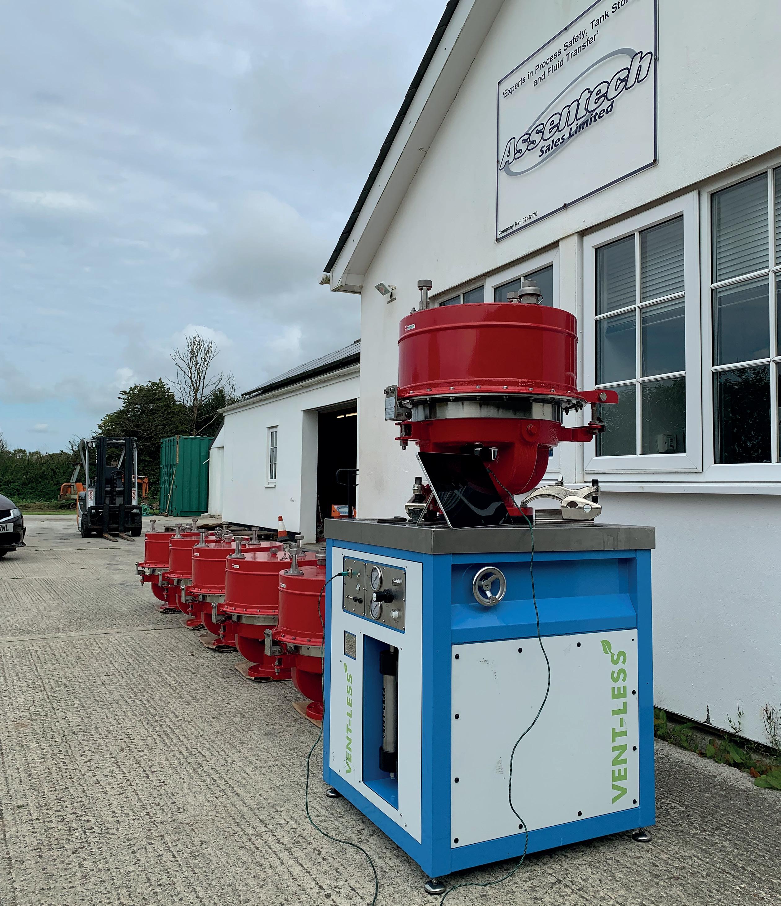
It is essential that a written scheme of examination is followed in order to benchmark valve condition and suitability for the application as time passes. Currently, there is not a wealth of information available to the operator or service company detailing how to service tank breather valves outside of individual manufacturers’ installation and operation manuals. As previously mentioned, with so many manufacturers skipping individual leak and calibration testing of new valves to API or ISO standards, they are unlikely to recommend this in the management of their devices as they age.
There is some guidance from API 576, but at this point in time it makes no reference to leak or calibration testing. The development of international standards relies on voluntary input by industry specialists, many of whom are employed by valve manufacturers. Preventing bias in the development of standards is therefore a significant challenge faced by the standards authorities. At present, this is still evident in API 576, as reference is made only to visual inspection of low-pressure devices, with no reference back to leak testing and calibration checks despite it being in API 2000 for design, manufacture and test of these devices when new.
It is therefore essential that more end users from refining and tank storage operators get involved in the development of standards to bring balance and a wider range of experience.
In order for a site to be productive, profitable and efficient, the assets that operate within it must be continually available, even if power is lost.
Flow control assets are often key pieces of equipment at a plant, providing essential duties for safe operation. Unplanned downtime can be costly and disruptive, affecting output yield, quality, and a company’s reputation.
Battery technology can provide solutions to a key problem that all operators and manufacturers face: how to ensure that production at a plant can continue even if a central power supply fails. The technology can help manufacturers to operate at peak efficiency and productivity.

The value of battery technology within valve actuation is substantial. In the event of mains power loss, a shutdown battery can continue to function automatically to a site-configurable end of travel safe position, providing fail-to-position functionality on critical valves within oil and gas applications.
Specific examples include valves that require emergency shutdown (ESD) and partial stroke testing (PST); plants dependent on unreliable power supplies; remote solar-powered sites; wellheads; diverter valves; or sites that require replacement for remote, process gas-powered pneumatic actuators.
Any downtime that has not been planned in advance, that is brought on by power supply issues, can have severe implications. If there is a loss of power, the process will typically fail-to-position right away (to guarantee safety and prevent product loss), but often operators want their applications to run as long as they can without power.
Safety is a key element to consider; if power is lost in the middle of an actuator’s action, the continued flow of a product may be dangerous. Flow control technology must provide a solution to ensure that, if desired, the process fails in a safe and controlled state.
Site uptime is essential, and battery technology can address power supply issues at critical locations, enabling flow control to continue to operate with the aid of a battery. A lithium-ion battery supplies back-up power from within the actuator enclosure, therefore maintaining benefits such as non-intrusive capability, hazardous area classification, and IP68 protection.
Lithium-ion batteries are small, light, efficient and dependable, and offer an operating life of up to 20 years. The battery charges automatically from the actuator mains (when mains power is on), saving time and improving efficiency. As the battery is charged, it has no impact on normal operations and its health can be monitored both locally and remotely, by way of intelligent actuators.
Actuators controlling the valve can either continue to run in the absence of electricity or safely cease the operation. Rotork’s intelligent electric IQT part-turn Shutdown Battery provides fail-to-position functionality in explosion-proof applications. The failure mode can be easily configured through the advanced set-up menu, depending on customer requirements. This fail-to-position can be fail-closed, open, stay put or go-to-a-percent position, depending on what fail-to-position action is needed to ensure that the process fails to a safe operating state. This means that the process concludes in a known and dependable state, preventing potential safety issues and avoiding monetary consequences due to loss of process control. With the shutdown battery, there is no need for additional back-up systems, such as compressors, to provide this functionality.
Another important function of a shutdown battery is its uninterruptible power supply (UPS) mode, providing power when the primary power supply is lost. The shutdown battery’s UPS allows for continued use of the actuator until battery charge is depleted, extending operation and control when power is lost or temporarily cuts out. Normal actuator service can be automatically restored on return of power, but it can also continue operating until the charge runs out. This mitigates the clear risks of lost revenue and interrupted action of flow control assets.
Site operators require a shutdown battery that is suitable for use in hazardous and EX areas. While other solutions, such as spring-return and hydraulic actuators, can provide some functionality, such as opening or closing the valve and therefore providing a fast-acting fail-safe action, they can be large and heavy.
The traditional method of storing energy for an actuator is through a spring. The mechanical nature of springs means that it
has to be 2.5 – 3 times the size needed for the valve, in order to generate sufficient torque.
The advantage of battery technology within an electric actuator is that the energy required to compress the spring is not needed. As such, it requires the size, torque and, ultimately, weight of the complete system.
Springs can also waste up to 5 – 10 W of electrical power. In order to be effective, the spring needs to be compressed and, in certain circumstances, held by a strong electromagnet, which constantly uses energy to remain on standby waiting for a potential power failure. This can also cause significant wear, as the actuator drives compression into the spring, through day-to-day operation.
Control is another significant advantage that battery-powered shutdown has over springs. Speed and torque cannot be controlled by a spring, but a shutdown battery can be programmed to fulfil the specific requirements of the operator.
The adjustable battery technology is significantly more flexible than spring-based alternatives. A shutdown battery can be programmed and given controlled logic to meet the needs of the user, while a spring is a single function, either open or closed.
Springs are adequate if the application requires a simple one-time closing, fast action fail-safe. However, batteries provide an extra level of control that enables the end user to be more flexible in their operation and make adjustments that are relevant to their specific needs.
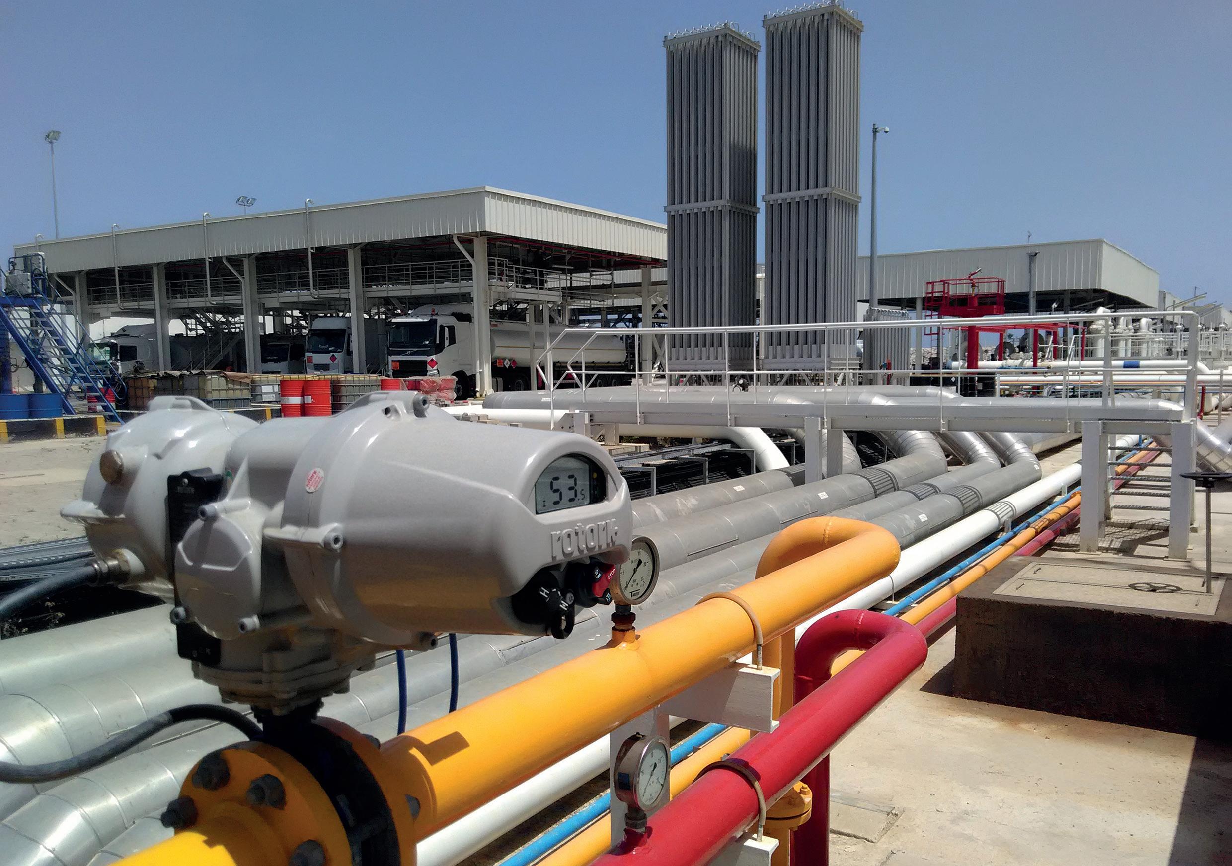
On tank farms, uptime is of critical importance. Any unplanned downtime through interruption of the power supply can significantly detract from operational goals and cause major financial and reputational damage. Intelligent actuation, combined with modern shutdown battery technology, presents a solution to the biggest obstacles to efficient tank farm site management.
An example of where a shutdown battery can mitigate the issue of downtime would be when an operator is trying to reach optimal mass balance and accuracy in the blending of the product constituents. In normal operation, valves open/close or move to a position on the loss of power, regardless of the site’s current blending status.
In the case of a power failure here, the previously mentioned UPS mode of the shutdown battery would take communicated instructions and allow the actuator to complete the correct process, even though the mains power was down.
Another area where a shutdown battery can make a difference is on truck-to-tank fuel loading bays. When transferring products such as gasoline or diesel to a tanker, there is a requirement to have one or two valves that are fail-close to avoid overfill. Flow begins with a connection to the tank and stops on disconnection. Usually, spring fail-safe close (FSC) actuators are used to ensure closure of the ball valve on disconnection of the fuel supply. However, the user will only know if a spring is broken through PST or after the failure.
A battery-powered intelligent actuator such as Rotork’s IQT3 can provide continuous diagnostics of its health and ability to close, reducing the risk of overspill situations and associated fines.
SHORT COURSES: SEPTEMBER 25, 2023


SYMPOSIA: SEPTEMBER 26 – 28, 2023

GEORGE R. BROWN CONVENTION CENTER • HOUSTON, TX
The Turbomachinery & Pump Symposia is recognized worldwide as the industry’s must-attend event. Connect with more than 4,750 delegates, meet with leading suppliers, observe product demos, and get answers to your technical questions. We look forward to seeing you in Houston!

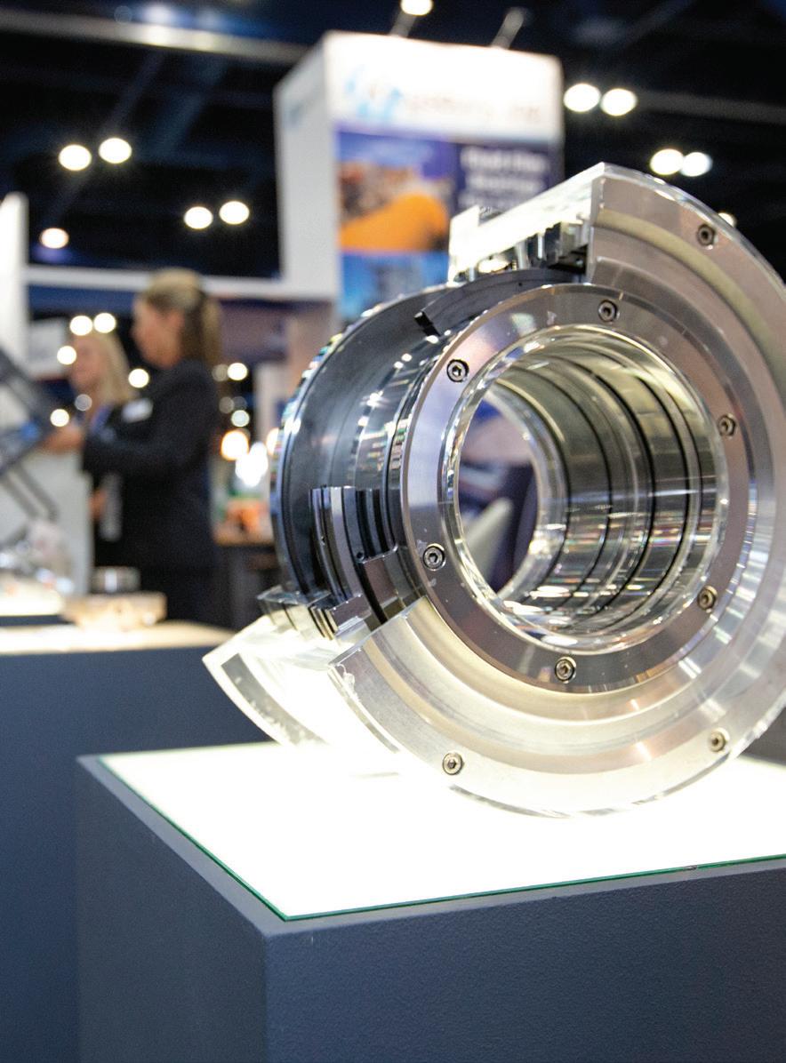
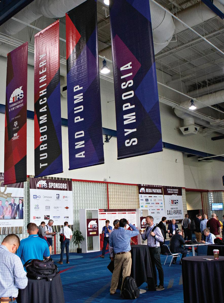
4,750 ATTENDEES
365 EXHIBITING COMPANIES


45 COUNTRIES
TPS.TAMU.EDU


#TPS2023
HOSTED BY
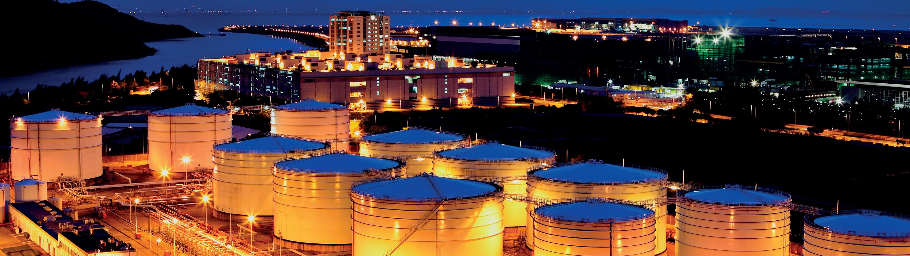
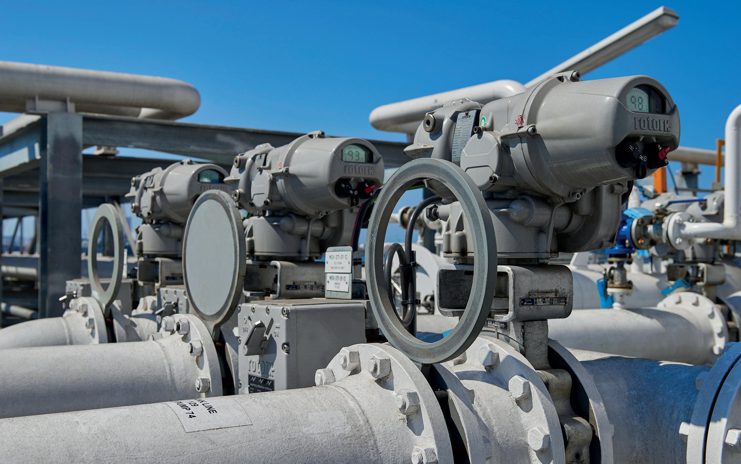
Oil and gas applications often feature lease automatic custody transfer (LACT) skids on the wellhead or terminals, which manage the transfer of products between companies. The role of the skid is to sample and measure oil quality. If there is too much sediment and water in the oil, then a diverter will route the oil to a separate oil tank. If the sediment levels are acceptable, then a valve will open and send the oil to the receiving company via a measuring demonstration such as a Coriolis meter.
A shutdown battery actuator has stored energy, which gives assurance that it will revert to a fail-to-position if the diverter
valve loses power. This means that there is no risk to oil quality, and reduced costs of reworking any contaminated oil. Additionally, as the majority of these skids are in remote locations, an intelligent actuator with a performance data logger allows for monitoring.
In the case of upstream production, ball valves are needed to prevent flow and isolate pressure if there is a loss of power and communications, which is usually managed through FSC actuation. This can lead to a wellhead shut-in, regardless of the duration of the power loss, and even in the case of a false alarm.
An intelligent actuator with programmable logic and shutdown battery integration, such as Rotork’s IQT, can allow for a delay before the fail-close operation occurs. In the event that power or communication systems temporarily drop out through an unreliable supply, the operation can still continue.
Flow control powered by battery technology is increasingly seen on various sites, across different markets. All sites that require flow control need these assets to provide reliable, safe and efficient operation. Actuators that can be powered by battery technology play a key role in ensuring the critical process uptime and production availability that is at the heart of a site’s success. Downtime can be costly and disruptive, especially for oil and gas production and tank farms/terminals. Battery-powered flow control technology can both extend operation where appropriate, and assist in bringing production to a safe halt if power supply is interrupted.


• From a tank gauge (It’s not Radar, Servo, Magnetostrictive, etc.) Bottom referenced (Innage)
• Provides the most accurate product volume (Inventory) (Transfer Ticketing)
• Provides Overfill Protection beyond API 2350 Standard, 5th Edition
• Provides Rupture Protection for Over Pressure & Vacuum on CRT’s
• Provides Leak Detection (Tank tightness, Historical) and Unauthorized Movement
• Provides Vapor Monitoring (Optional ambient vapor monitoring)
• Provides Product Quality by continuous monitoring of product stratification over the height of the liquid (Water, Density, & Temperature) (Blending, De-watering, Sampling Top-Middle-Bottom in real-time, etc.)
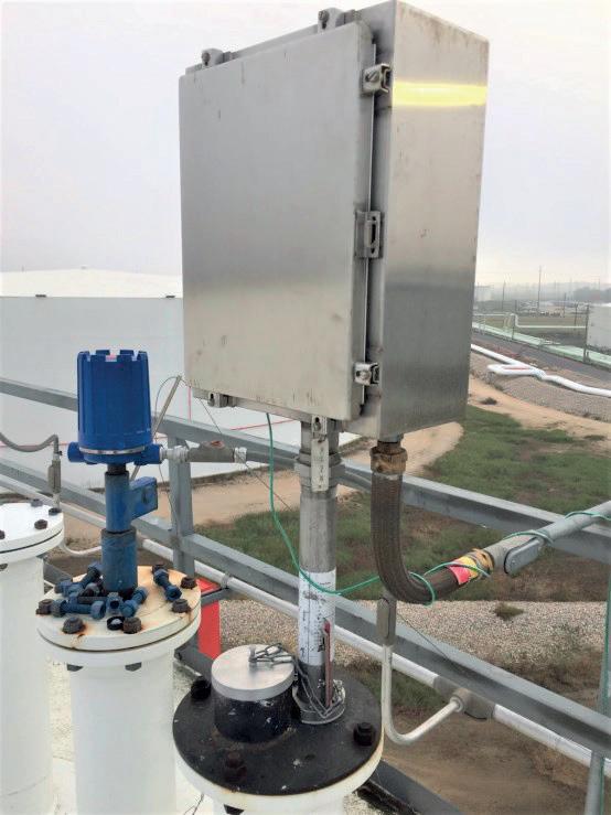
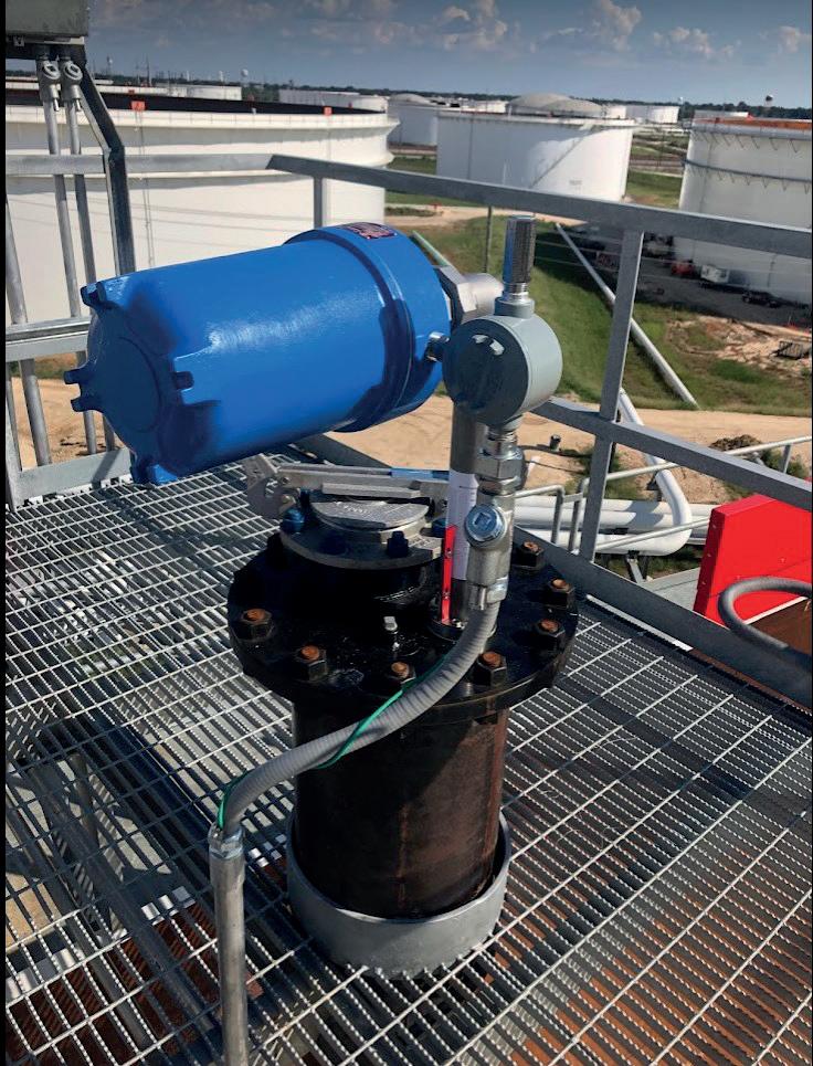
• And provides this data to any system via a closed server with OPC/UA, PI, SAP, MQTT, Back Office, etc. connectivity (Real-time or Scheduled)
• TG Soft Server supports multiple applications that are tailored to providing a payback and profit from your gauging technology. What data do you need?