

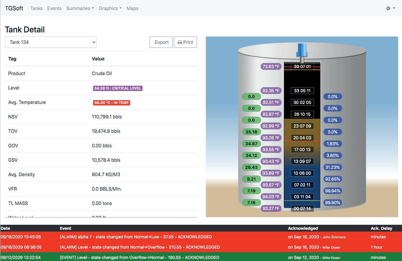
• From a tank gauge (It’s not Radar, Servo, Magnetostrictive, etc.) Bottom referenced (Innage)
• Provides the most accurate product volume (Inventory) (Transfer Ticketing)
• Provides Overfill Protection beyond API 2350 Standard, 5th Edition
• Provides Rupture Protection for Over Pressure & Vacuum on CRT’s
• Provides Leak Detection (Tank tightness, Historical) and Unauthorized Movement
• Provides Vapor Monitoring (Optional ambient vapor monitoring)
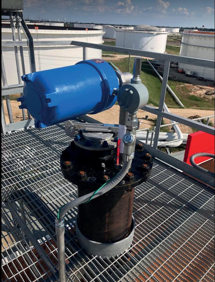
• Provides Product Quality by continuous monitoring of product stratification over the height of the liquid (Water, Density, & Temperature) (Blending, De-watering, Sampling Top-Middle-Bottom in real-time, etc.)
• And provides this data to any system via a closed server with OPC/UA, PI, SAP, MQTT, Back Office, etc. connectivity (Real-time or Scheduled)
• TG Soft Server supports multiple applications that are tailored to providing a payback and profit from your gauging technology. What data do you need?


21 The new old-fashioned
and energy security in Asia
Ng Weng Hoong, contextualises the push for energy security and stockpiling in major Asian energy storage markets.

11 Final revisions to industry air regulations
Harold Laurence, Trinity Consultants Inc., USA, discusses the implementation and ramifications of the US EPA’s finalised proposed revisions to emission standards for the gasoline distribution industry.
17 Venting the vapour
Bernat Sala, Tecam, Spain, explores the necessity of gas venting emissions treatment and vapour recovery


Thomas Kemme, AMETEK Level Measurement Solutions, USA, discusses how traditional level measurement techniques can be enhanced.
25 Finding the right frequency
Gregory Tischler, VEGA Americas, USA, examines how a tank farm can benefit from the installation of modern radar level sensor solutions.
29 Keeping operations flowing
Dave Godfrey, Rotork, UK, explains why maintaining actuators should be a top priority for terminal operators.
33 Standing strong with VCIs
Ted Huck, Matcor, proposes how vapour corrosion inhibitors (VCIs) can be used to combat corrosion damage on tank bottoms.
37 From tanks to tankers
Harry Smith, Atmos International, UK, discusses how to improve storage operations with pipeline technology.
41 Ensuring safety and efficiency
Mark Naples, Umicore Coating Services, considers the benefits of infrared gas detection in the oil and gas storage sector.
45 A step change in risk reduction
Chris Platt, Re-Gen Robotics, discusses how the adoption of a robotic tank cleaning philosophy can significantly reduce safety risks
48 Industrial strength solution
Roger Simonsson, Aquajet, Sweden, explains the benefits of robotic hydrodemolition equipment for oil and gas tank cleaning.
53 Comprehending cybersecurity
Tim Gale, 1898 & Co., emphasises the importance of implementing an effective cybersecurity programme.
Eddyfi Technologies offers advanced non-destructive testing solutions designed to ensure the integrity and safety of tanks and vessels. From comprehensive ultrasonic inspections to state-of-the-art robotic systems, the company’s technology delivers precise, reliable data to meet rigorous inspection demands, securing storage across industries. Discover more at eddyfi.com.


MANAGING EDITOR James Little james.little@palladianpublications.com
SENIOR EDITOR Callum O’Reilly callum.oreilly@palladianpublications.com
EDITORIAL ASSISTANT Oliver Kleinschmidt oliver.kleinschmidt@palladianpublications.com
SALES DIRECTOR Rod Hardy rod.hardy@palladianpublications.com
SALES MANAGER Chris Atkin chris.atkin@palladianpublications.com
SALES MANAGER Will Powell will.powell@palladianpublications.com
SALES EXECUTIVE Ella Hopwood ella.hopwood@palladianpublications.com
PRODUCTION MANAGER Kyla Waller kyla.waller@palladianpublications.com
EVENTS MANAGER Louise Cameron louise.cameron@palladianpublications.com
DIGITAL EVENTS COORDINATOR Merili Jurivete merili.jurivete@palladianpublications.com
DIGITAL CONTENT ASSISTANT Kristian Ilasko kristian.ilasko@palladianpublications.com
DIGITAL ADMINISTRATOR Nicole Harman-Smith nicole.harman-smith@palladianpublications.com
ADMIN MANAGER Laura White laura.white@palladianpublications.com
CONTRIBUTING EDITOR Gordon Cope
SUBSCRIPTION RATES
Annual subscription £110 UK including postage /£125 overseas (postage airmail). Two year discounted rate £176 UK including postage/£200 overseas (postage airmail).
SUBSCRIPTION CLAIMS
Claims for non receipt of issues must be made within 3 months of publication of the issue or they will not be honoured without charge.
APPLICABLE ONLY TO USA & CANADA
Hydrocarbon Engineering (ISSN No: 1468-9340, USPS No: 020-998) is published monthly by Palladian Publications Ltd GBR and distributed in the USA by Asendia USA, 17B S Middlesex Ave, Monroe NJ 08831. Periodicals postage paid New Brunswick, NJ and additional mailing offices. POSTMASTER: send address changes to HYDROCARBON ENGINEERING, 701C Ashland Ave, Folcroft PA 19032
15 South Street, Farnham, Surrey GU9 7QU, UK
Tel: +44 (0) 1252 718 999 Fax: +44 (0) 1252 718 992

CALLUM O’REILLY SENIOR EDITOR
As we approach the end of another summer here in the northern hemisphere, thoughts are turning to the darker (and colder) nights ahead (I have already spotted Christmas decorations in some of my local shops – in August!). Thankfully, there is little concern about the lights going out here in Europe during the winter 2024/25 season, as the continent sits in a comfortable position in terms of its energy storage. In its ‘Europe gas and LNG markets short-term outlook Q2 2024’ report, Wood Mackenzie forecasts that European gas storage will reach 100% by the end of September and remain full until the end of October.1 The data and analytics company expects an additional 4 million tpy of floating storage to also be accumulated.
The report states that low European demand for gas has kept storage levels at record highs this year, despite the fact that the continent has imported 11 million tpy less LNG through May 2024, compared to the same period in 2023. This lower demand depressed prices and pushed LNG into Asia, with imports to China up 22%. Wood Mackenzie anticipates an increase in gas demand of 7 billion m3 in 2025 compared to 2024, if there is a return to normal weather dynamics over the coming winter, and due to a strengthening macroeconomic outlook across Europe.
Wood Mackenzie expects Asia to absorb most of the new LNG that is coming online, although Europe is likely to import an extra 4.2 million tpy compared to 2024. More than 40 million tpy of LNG supply growth is expected in 2026, with Asian demand once again expected to account for a significant amount of this new supply, but Europe will absorb almost 20 million t of additional LNG in 2026, which will put downward pressure on prices.
This issue of Tanks & Terminals takes a deeper dive into Asia’s oil and gas storage sector. Contributing Editor, Ng Weng Hoong, guides us through the latest developments in the region, shining a spotlight on a number of countries including India, China, Singapore and Papua New Guinea. This issue also includes detailed technical articles and case studies on a number of interesting topics. Starting on p. 11, Trinity Consultants considers the implementation and ramifications of the US Environmental Protection Agency (EPA)’s finalised proposed revisions to emissions standards for the gasoline distribution industry. Other articles cover the importance of gas venting emissions treatment and vapour recovery technology, level measurement techniques, actuator maintenance, corrosion protection, pipeline technology, robotics, cybersecurity, and much more. I hope you enjoy this issue, and if you are picking up a copy at the AFPM Summit or the NISTM’s 17 th Annual National Aboveground Storage Tank Conference & Trade Show, I invite you to register for a free subscription to the magazine by scanning the QR code.

1. ‘Higher LNG prices to limit Asian demand and turbocharge European gas storage levels’, Wood Mackenzie, (12 June 2024), https://www.woodmac.com/press-releases/higher-lngprices-to-limit-asian-demand-and-turbocharge-european-gas-storage-levels/








At the Gate terminal in Rotterdam, the Netherlands, Uniper has become the first shipper to start using the BioLNG production capacity to convert biomethane into BioLNG. The underlying commodity is biogas produced in one of the EU member states, upgraded to biomethane to remove substances such as carbon dioxide, hydrogen sulfide and fed into the Dutch natural gas grid.
In its latest ‘Short-Term Energy Outlook’, the US Energy Information Administration (EIA) forecast that US working natural gas inventories will be 3954 billion ft3 by the end of October 2024, the most natural gas in US storage since November 2016.
Neste has commissioned terminal capacity at ONEOK’s terminal in Houston, Texas, US, for blending and storing Neste MY Sustainable Aviation FuelTM. The new capacity at ONEOK’s terminal provides Neste with storage capacity of up to 100 000 t (around 33.5 million gal.) and is directly connected to the energy pipeline infrastructure in the eastern part of the US.
GAS Entec, with its group company AG&P and local partners Issa Haddadin, have been awarded a contract to build the Sheikh Sabah Al-Ahmad Al-Jaber Al Sabah onshore regasification LNG terminal at Port of Aqaba in the Kingdom of Jordan. The project’s scope encompasses full engineering, procurement, construction, installation, and commissioning (EPCIC) of a 720 million ft3/d onshore LNG regasification facility, marine works, jetty topside work and other associated components.
To keep up-to-date with the latest news and developments in the storage sector, visit www.tanksterminals.com and follow us on our social media platforms

17 20 September 2024
07 10 October 2024
Storage Tank Conference & Expo Fort Lauderdale, Florida, USA events.api.org/2024-api-storage-tank-conference-expo
20 November 2024 Global Hydrogen Conference Virtual www.accelevents.com/e/ghc2024
10 12 December 2024 17th Annual National Aboveground Storage Tank Conference & Trade Show The Woodlands, Texas, USA www.nistm.org
11 12 March 2025 StocExpo Rotterdam, the Netherlands www.stocexpo.com
23 25 April 2025 27th Annual International Aboveground Storage Tank Conference & Trade Show Orlando, Florida, USA www.nistm.org
09 11 June 2025
ILTA 2025 International Operating Conference & Trade Show Houston, Texas, USA www.ilta.org/events-training


Ng Weng Hoong, Contributing Editor, contextualises the push for energy security and stockpiling in major Asian energy storage markets.

The International Energy Agency (IEA) has reiterated its prediction that global oil demand will peak by the end of the 2020s. But it is falling on deaf ears in Asia, with India and China continuing to invest in the entire oil supply chain covering exploration, production, refining, distribution, trading, and stockpiling. While the crude oil price has stabilised in the US$80/bbl range with no immediate threat to supply, India and China are beefing up their stockpiling capabilities as if to prepare for severe shortages in the coming years.
India will likely lead Asia’s expansion of liquid storage capacity over the next five years under the government of Prime Minister Narendra Modi which recently won re-election for a third term in office.
Between 2024 and 2028, India will add 22 million t of capacity to account for 42% of the region’s storage project start-ups, according to GlobalData. Furthermore, S&P Global suggests the Modi government will prioritise investment in the oil and gas sector to support the country’s economy and quest for energy security.
Oil storage and logistics will be priority projects, with the government responsible for 47% of the increase in India’s stockpiling capacity through the state-owned strategic petroleum reserves (SPRs), as suggested by GlobalData Analyst, Bhargavi Gandham. State agency ISPR Ltd (ISPRL) has been tasked to add 4 million t of capacity in Odisha state, 4 million t in Rajasthan, and 2.5 million t in Karnataka under the second phase of the SPR expansion programme.
Located in Chandikhol town, the US$1.1 billion Odisha terminal will be the country’s largest and most sophisticated after its slated start up in 2028. The terminal will be located 85 km from the north-eastern deep-water port of Paradip.
A proposed inland terminal at Bikaner town in Rajasthan, located 465 km from the India-Pakistan border, will be India’s fourth official crude oil storage site. State-owned Engineers India Ltd (EIL) has enlisted a German firm to help build a salt-cavern facility in the hilly rocky geology of the country’s arid north-western state.
While the idea of storing oil in man-made caverns has been around for decades, India lacks the technology to extract salts embedded in the rocks to eliminate the risk of fuel contamination. At the same time, engineers must ensure the caverns are completely stabilised after the salts are removed.
The world’s third largest oil consuming country is also building its first commercial crude
stockpiling terminal in Padur in Karnataka, located near ISPRL’s existing SPR facility. The underground rock cavern will be served by a dedicated single-point moor, and a set of onshore and offshore pipelines to be constructed on a budget of Rs.55.1 billion (US$1 = Rs.84).
While India has made progress in its stockpiling efforts, it is still a long way from meeting international standards for achieving energy security.
In a special report in early 2024, the IEA praised the Indian government for planning to bolster its SPR while promoting biofuels and energy efficiency measures to reduce domestic oil use and imports.
But the Paris-based agency is also urging India to hasten the pace of oil stockpiling to meet the international standard of 90 days of imports. It wants the Modi government to do more to prepare for “possible oil supply disruptions by implementing and strengthening its SPR programmes and improve its oil industry’s readiness.”
India had oil stocks to cover just 66 days of imports at the start of 2024, said the agency. This includes 26 million bbl stored in ISPRL sites and 218 million bbl in privately-owned terminals. India’s stockpiling efforts are not keeping pace with the rapid growth of its 5.6 million bbl/d market. The IEA projects the country’s oil consumption to rise by 1 million bpd over the next six years to 2030.
In response, the Modi government could ask Indian refineries to set up strategic sites to stockpile up to three days of net imports at up to six different locations.
“This could rapidly boost India’s overall strategic oil stock holdings by between 10 – 18 days of imports,” said the IEA.
India established the ISPRL in 2005 to launch the country’s strategic stockpiling programme. The first phase was completed with the construction of a total of 5.33 million t of storage capacity in 2018. The tanks are in the ports of Visakhapatnam (1.33 million t) on the south-eastern state of Andhra Pradesh, and in Mangaluru (1.5 million t) and Padur (2.5 million t), both in Karnataka on the west coast.
India is seeking to join the IEA, which wants members to comply with its 90-day stockpiling guideline.
Meanwhile, China has issued an unexpected order for state-owned firms to add 8 million t
(58.8 million bbl) of crude to their strategic stockpiles from July to March 2025, said oil and gas intelligence provider Vortexa. This translates to approximately 220 000 bpd of additional crude demand, equal to about 2% of China’s seaborne imports, said Vortexa’s Senior Analyst Emma Li. The additional buying is expected to be shared by the country’s leading state companies – China National Petroleum Corp. (CNPC), Sinopec, China National Offshore Oil Corp. (CNOOC), Sinochem, and Zhenhua Oil.
China’s stockpiling appears to have picked up recently after a lull from late 2023 to mid-May 2024. In June, its onshore crude inventories built “a moderate 8 million bbl month-on-month to 954 million bbl,” said Li.
By end-June, PetroChina, Sinopec, CNOOC, and Sinochem, informally known as the ‘Big Four’, had stockpiled a total of 665 million bbl of crude oil in aboveground oil tanks to add to the 100 – 110 million bbl in underground reserves.
According to Vortexa’s estimate, the combined tank utilisation rate has recently exceeded 60%, suggesting the companies have room to restock in the July-to-March window.
Until Beijing’s latest stockpiling order, China’s slowing oil demand was weighing on its crude buying.
“The stock build rate dropped from 1.2 million bpd to less than 150 000 bpd in the second half of May, as crude imports slowed by 1.1 million bpd in the three consecutive weeks ending on 2 June, compared to the preceding three weeks,” wrote analyst Li.
China’s onshore crude inventories rose throughout May, but the stockpile buying lasted just four weeks, compared to the typical duration of 10 – 14 weeks in previous years.
Crude demand remains weak as refiners have reduced throughput, reflecting the country’s slowing demand for refined products. This is linked to the state of China’s economy which has become a subject of speculation given the lack of reliable information flow. Beijing reported that the economy grew by 5.3% in the 1Q24, exceeding its targeted growth of 5% as well as the average 4.6% expectations of analysts polled by Reuters.
The Chinese government has been boosting spending and talking up the country’s economic prospects, but consumer confidence remains weak and foreign investors have been heading for the exit while the real estate and technology sectors are mired in gloom.
The oil markets are not supporting Beijing’s narrative that the economy is fully recovering. According to Vortexa’s calculations, China’s implied refinery runs have declined for the third straight month to 14.5 million bpd in May, marking a year-on-year contraction for four consecutive months.
“This suggests that current run cuts are deeper than the scheduled capacity offline for turnarounds, and post-maintenance crude demand is unlikely to rebound to last year’s [2023] levels in the coming months,” observed Li.
Significantly, China’s three largest refiners, Sinopec, PetroChina and CNOOC, slowed down their stockpiling of crude in 2023. While adding a total of more than 120 million bbl of tank storage capacity, they increased crude stockpiles by only 85 million bbl at the end of 2023.
In February 2024, CNOOC added a crude oil reserve storage base in the coastal city of Dongying in eastern Shandong province alongside tanks that have long supported offshore production. The new tank farm has been receiving Russia Far East’s Eastern Siberia Pacific Ocean (ESPO) crude blend, reaching a record 910 000 bpd in March, said Vortexa. According to Chinese state media, the new farm comprises 50 crude oil tanks with a combined capacity to store 4.25 million t of crude oil. Located on a 1.2 million m² site, it has direct access to the Bohai Sea, the main source of China’s domestic offshore oil production.
Connected by pipelines to the offshore oilfields, the expanded terminal will store and distribute the crude to nearby refineries. CNOOC plans to more than triple the terminal’s capacity to 15 million t at a cost of CN¥20 billion (US$1 = CN¥7.25).
The company is also investing CN¥3 billion to build an underground commercial oil terminal in Ningbo port in Zhejiang province. When completed in 2026, the Daxie terminal will have the capacity to store 3 million m³ of crude oil for distribution to nearby refineries.
Singapore may have to reckon with how much more oil, gas, and chemicals it can store, trade, blend, and ship on its increasingly congested waterways.
With little room to increase land-based storage capacity, Singapore’s traders have been expanding their oil and gas trading and supply activities in the waters around the Southeast Asian island state since the turn of the century.
Now, even the waterways are feeling the strain of runaway growth. On 14 June, some 400 t of oil spilled after an accident involving a Dutch dredging boat and a stationary bunker tanker off southern Singapore. Residents and tourists in the polluted parts of the island’s beaches and coastal waters experienced breathing difficulties while businesses complained they suffered heavy losses. The government stated the island’s farmed fish and water supply remained safe for consumption even as it denied that the incident was the result of port congestion.
Coming on the back of another year of record shipping and bunker activity in Singapore, the industry has been eyeing opportunities for storage expansion. But it also raises the risk of more shipping accidents and liquid spillages.
Early in 2024, Vopak announced its plans to expand its range of services in Singapore. In March, it signed an agreement with Air Liquide to develop and operate infrastructure for serving the ammonia and hydrogen trade. The companies stated that they will explore the potential joint development of ammonia cracking, storage, and handling infrastructure at Vopak’s Banyan terminal, and the distribution of low-carbon hydrogen through a hydrogen pipeline network.
Located on Jurong Island, Vopak Banyan is an integrated oil, chemical, and gas hybrid storage terminal. Its 112 tanks have a total storage capacity of 1 452 163 million m³.
In February, Vopak announced the commissioning of 40 000 m³ of storage capacity at its Sebarok terminal for blending biofuels into marine fuels. The company said it converted the terminal’s existing pipeline system to specially


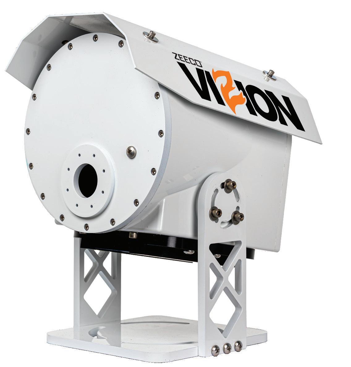
ZEECO® ViZionTM remotely measures, monitors, and controls flare performance to achieve 98% DRE or better. Approved by the EPA for measuring and quantifying NHVdil and NHVcz parameters – ViZion complies with OOOOb/c and AP 42 regulations utilizing simplified video imaging spectro-radiometry (VISR) technology. Because ViZion directly verifies the flare flame and heat release, there is no need for pilot flame confirmation, calorimeters, gas chromatography, mass spectroscopy, or canister sampling. Zeeco – Redefining Flare Monitoring and Control.


handle biofuel blending. Sebarok is located close to the eastern anchorage, where much of Singapore’s bunkering activity takes place.
Vopak said its decision to venture into biofuels storage and blending in Singapore came at the end of a two-year trial to provide the service in response to rising demand. It said it could ‘repurpose’ part of the terminal’s 1 339 579 m³ capacity to support the biofuels trade.
Rob Boudestijn, the company’s President in Singapore, said: “Our vision for the Sebarok terminal is to be a sustainable multi-fuels hub to strengthen Singapore’s position as the top bunkering hub. As a storage and critical infrastructure services provider, this development can facilitate the entry of more biofuels companies to diversify the supply chain for marine biofuels and accelerate the decarbonisation of the shipping industry.”
Another global trading and storage player, Vitol, has taken delivery of its first barge in Singapore dedicated to storing and transporting biofuels for bunker use. The barge is equipped to store and supply biofuel blends of grades ranging from B24, B30 to B100.
Biofuels are being touted as a solution to reduce greenhouse emissions in the shipping industry. Citing the Maritime and Port Authority of Singapore (MPA), Vitol said biofuel sales in Singapore reached 520 000 t in 2023, compared with 140 000 t in 2022.
Papua New Guinea has been seeking investments in oil refining and storage facilities to help solve its multi-year fuel supply crisis that is threatening the country’s political stability and economic prospects.
Prime Minister James Marape believes the projects will create jobs and boost the economy while improving fuel supply security for the nation’s 26 million people living on some 600 islands across the Pacific Ocean.
Acute fuel shortages over the past 18 months have contributed to the economy’s sharp slowdown and rising inflation that led to deadly riots in several cities including the capital of Port Moresby in January. At least 22 people were killed.
In March, Marape and Petroleum Minister Jimmy Maladina flew to Singapore to meet oil executives from Chinese state firms Sinopec and Petro China.
“We are in initial discussions with reputable global fuel traders who are in the business of refining fuel, bunkering, and retail distribution. Papua New Guinea can be a strategic hub to supply the Pacific,” said Marape.
“We want to open the market and remove monopoly. The government’s role is to ensure that the country gets the correct price, quality and reliability into the future to avoid the predicament we are experiencing with Puma Energy.”
Singapore-based Puma Energy, which has a near monopoly of Papua New Guinea’s downstream oil markets, has been at loggerheads with the government over the fuel supply crisis that has severely disrupted transportation services across the country. The frequent disruption to vital air links between the islands has led to shortages of goods and services.
The government has been pushing for greater fuel supply competition that could see increased participation from
Chinese and American companies. Marape believes their involvement could also turn his country into an oil refining and storage hub to serve the economies of the islands in the Pacific Ocean.
ExxonMobil has emerged as a key player, with Marape personally thanking the company’s Singapore operations for providing emergency supplies over the past year.
In May, Mobil Oil Guinea, a subsidiary of ExxonMobil, commissioned a new 3.5 million l storage tank at its Idubada terminal in Port Moresby to increase fuel imports from Singapore. The PGK10 million tank’s launch has had an immediate impact in easing the country’s supply shortages of gasoline, diesel and jet fuel (US$1 = PGK3.85).
While Papua New Guinea’s fuel crisis is far from over, the government will be heartened by Mobil Oil Guinea’s decision to expand the Idubada terminal as part of an PGK80 million investment programme.
BW LPG has been aiming for growth in Asia on the back of its first venture in fuel import and storage in India, a secondary listing on the New York Stock Exchange, and the relocation of its headquarters to Singapore.
The Oslo, Norway-listed company, the world’s leading owner and operator of LPG vessels, has begun implementing a multi-pronged strategy to tap into India’s growing demand for the fuel.
In November 2023, it paid US$30 million for an 8.5% stake in Confidence Petroleum India Ltd, an LPG company with exposure to India’s industrial, automobile, and domestic retail sectors.
The two companies also agreed to establish an equal joint venture, BW Confidence Enterprise Private Ltd, to explore investment opportunities in onshore infrastructure in India to store and import LPG. Based in Mumbai, BW Enterprise will collaborate with BW LPG’s trading division and its India subsidiary, BW Product Services, and BW LPG India to source and import LPG to meet the country’s growing fuel demand.
Separately, BW LPG also announced that it had invested US$10 million to jointly develop and operate a new LPG onshore import terminal at Mumbai’s Jawaharlal Nehru Port Association (JNPA) Port with Ganesh Benzoplast, a Mumbai storage tank builder and operator. The Norwegian firm will be represented by BW Confidence which will hold a 55% stake in a cryogenic LPG storage terminal facility currently being developed at JNPA’s facility.
Due to start up in 2026, the terminal will be equipped to fully offload the latest fourth-generation very large gas carriers (VLGC) of 93 000 m³ capacity in a single discharge operation. The partners are planning to link the terminal to the Uran Chakan pipeline to ensure competitive and efficient supply of LPG into India.
India is the world’s second largest LPG consumer with the potential for rapid growth with the support of improved infrastructure to import, store and distribute the fuel. BW LPG will be better positioned to service India from its new headquarters in Singapore following relocation from Bermuda. The company will also have improved access to funding following its listing on the NYSE in April to tap the world’s largest capital markets.
Harold Laurence, Trinity Consultants Inc., USA, discusses the implementation and ramifications of the US EPA’s finalised proposed revisions to emission standards for the gasoline distribution industry.
On 8 May 2024, the US Environmental Protection Agency (EPA) finalised proposed revisions to emission standards for the gasoline distribution industry.¹ The final rules became effective on 8 July 2024.² These standards affect storage tanks, loading racks, and equipment components at thousands of gasoline distribution terminals, bulk plants, pipelines, and refinery logistics assets.³ The revisions include several important increases in stringency, such as lower numeric emission limits, additional monitoring, and shorter averaging periods.
Most standards and requirements of the final rules follow the rules proposed on 10 June 2022. Compared with the proposed rules, the final rules provided additional flexibility on certain matters. The EPA provided alternative, flare-like monitoring provisions for vapour combustion units (VCUs) in each rule;4 loosened the inspection schedule for internal floating roof (IFR) tank lower explosive limit (LEL) enhanced monitoring;5 and provided a continuous emission monitoring system (CEMS) downtime option for vapour recovery units (VRUs).6 The EPA clarified that methane may be excluded when measuring emissions to compare with the standards for loading racks.7 The EPA also separated the applicability of equipment leak detection and repair (LDAR) standards from the applicability of standards for loading operations.8 Under the final rule, projects that increase fugitive emissions from rack equipment (pumps, valves, etc.) without increasing emissions from loading operations would not subject those loading operations to new standards.9
On the other hand, the EPA markedly increased monitoring stringency for VCUs, for open flares, and thus also for VCUs that choose to rely on the final rules’ open
flare monitoring parameters. To comply with the final rule, operators must know the prior loads of each loaded cargo compartment: an unworkable requirement for many terminals. If unworkable, the terminal must treat vapours from every loaded compartment as though they are gasoline.10 If the terminal controls vapours with a VCU, the terminal must maintain high temperature or vapour net heating value (NHV) through the addition of substantial volumes of assist gas.11 Increased emissions of combustion pollutants and substantially increased operational costs are likely outcomes of the final rule.
The EPA has regulated volatile organic compound (VOC) emissions from the gasoline distribution sector under its new source performance standards (NSPS) regulatory programme (40 CFR Part 60) since the 1983 promulgation of ‘Standards of Performance for Bulk Gasoline Terminals,’ 40 CFR Part 60, Subpart XX.12 The NSPS required most gasoline truck loading racks built or modified between 17 December 1980 and 10 June 2022 to meet an emission standard of 35 mg/l total organic compounds (TOC) of gasoline loaded (mg/l TOC).13 The NSPS required monthly monitoring of loading rack equipment for leaks, by audio, visual, and olfactory (AVO), or put more simply, sight/sound/smell means.14 NSPS XX also introduced vapour tightness requirements for gasoline tank trucks.15
In 1994, the EPA promulgated an emission standard regulating hazardous air pollutant (HAP) emissions from HAP major source gasoline terminals and pipeline breakout stations: ‘National Emission Standards for Gasoline Distribution Facilities (Bulk Gasoline Terminals and Pipeline Breakout Stations),’ 40 CFR Part 63, Subpart R (Subpart R).16


This subpart required gasoline truck and rail loading racks to meet 10 mg/l TOC.17 Subpart R required gasoline storage vessels to install an IFR meeting most requirements of 40 CFR Part 60, Subpart Kb,18 and to retrofit certain deck fittings on existing gasoline storage vessels with external floating roofs (EFRs).19
Subpart R required monthly AVO leak inspections, but the scope included all gasoline-service equipment at the terminal or breakout station.
Subpart R only affected larger terminals and breakout stations, those that met the EPA’s HAP major source threshold. By 1999, the EPA had indicated its intent to regulate gasoline distribution facilities that did not rise to the HAP major source threshold – such sources are known as ‘area sources’ of HAP.20
In 2008, the EPA promulgated 'National Emission Standards for Hazardous Air Pollutants for Source Category: Gasoline Distribution Bulk Terminals, Bulk Plants, and Pipeline Facilities,'
40 CFR Part 63, Subpart BBBBBB (Subpart 6B).21 Subpart 6B contained different sets of requirements for four source categories: bulk gasoline terminals, bulk gasoline plants (a throughput of less than 20 000 gal./d), pipeline pump stations, and pipeline breakout stations.
The EPA is required to review NSPS, such as 40 CFR Part 60, Subpart XX, and National Emission Standards for Hazardous Air Pollutants (NESHAP), such as 40 CFR Part 63, Subparts R and 6B, at least every eight years.22 If needed, the EPA must revise the subparts to reflect the best demonstrated system of emission reduction (for NSPS) or to take developments in control technology into account (for NESHAP, a ‘technology review’). Table 1 presents the EPA’s key revisions of the three subparts as they apply to bulk terminals. The EPA adopted new or more
Table 1. Selected 2024 final rule changes from 2022 Proposed Rule for Subpart XXa and Subparts R and 6B, for equipment at bulk gasoline terminals, pipeline pump stations, and pipeline breakout stations
Affected source type
Vapour combustion units (VCUs)b
XX, XXa XX: 35 mg/l TOC for truck racks new/modified after 17 December 1980
80 mg/l existing 6 hr average
Vapour recovery units (VRUs)c
Open flares on loading racksd
• 1 mg/l TOC for new racks. 3 hr average
• 10 mg/l for modified/ reconstructed racks. 3 hr average
R 10 mg/l TOC. 6 hr average 10 mg/l TOC. 3 hr average
6B 80 mg/l TOC for racks > 250 000 gal./d. 6 hr average
XX, XXa Same as VCUs
35 mg/l TOC for racks > 250 000 gal./d. 3 hr average
• 550 ppmv TOC as propane. 3 hr average at new racks
• 5500 ppmv for modified/ reconstructed racks
R 5500 ppmv TOC as propane. 3 hr average
6B 19 200 ppmv TOC as propane. 3 hr average
XX/XXa, R, 6B
General flare standards:
§60.18 (XX) or §63.11(b) (R, 6B)
Gasoline storage tanks subject to Subpart R or 6B standardse R, 6B IFR or EFR
• See subparts for rim seal and deck fitting requirements
XXa: no flares allowed for new racks Racks modified or reconstructed in XXa, or subject to R or 6B, may meet refinery flare rules at § 63.670(b)
• EFR tanks’ deck fittings must fully meet Part 60, Subpart Kb
• IFR tanks must conduct LEL monitoring during annual inspections. LEL threshold is 25%, 5 minute average. LEL data to be collected every 15 sec. for at least 20 minutes
Methane may be excluded from measured TOC in all subparts. Monitoring NHV and NHVdil as though the unit is an open flare was added as an option under all subparts.
Equipment in gasoline servicef (also applies to bulk plants under 6B)
XX/XXa, R, 6B
Monthly AVO leak inspection, with leaks repaired
Method 21 leak monitoring or optical gas imaging
10 000 ppm leak definition for Method 21
• XXa: Quarterly
• R: Semiannual
• 6B: Annual
Methane may be excluded from measured TOC in all subparts. Clarity added, that the rules do not prohibit purge air.
240 hr/yr CEMS downtime alternative added, but the option limits throughput and relies heavily on activity in 10 regen cycles preceding the downtime.
Final rule added requirements to track gasoline load ratio, and gasoline load rate for air-assisted flares, to prevent overdilution.
Flare tip velocity monitoring reduced to a one-time assessment.
LEL required annually, but not necessarily at the same time as a visual inspection. Wind speed limitation of 10 mph revised; OK to use 15 mph if not practicable to make timely measurement during < 5 mph.
Separate XXa affected facility 'collection of equipment' definition. Modifying ‘equipment’ and beginning LDAR does not mean modifying the ‘loading rack’ and applying new mg/l or ppm standards, and vice versa.
a. Subpart XX requirements are not revised in the present rulemaking. Existing loading racks would comply with Subpart XXa after they are modified or reconstructed, and Subpart XX until then.
b. Current: §§ 60.502(a)-(b), 63.422(b), Subpart 6B Table 2 Item 1. New final: §§ 60.502a(b)(1), (c)(1), 63.422(b)(2), Subpart 6B Table 3 Item 1.
c. Current: same as VCU. New final: §§ 60.502a(b)(2), (c)(2), Subpart 6B Table 3 Item 3.
d. Distinct from VCUs. Current: §§ 60.503(e), 63.425(a)(2), 63.11092(a)(4). New final: §§ 60.502a(c)(3), Subpart 6B Table 3 Item 2.
e. Under Part 63, Subparts R and 6B, tanks < 75 m3 (19 800 gal.) are exempt. Under Subpart 6B only, tanks from 75 to 151 m3 (19 800 to 39 800 gal.) are also exempt, if the tank’s throughput is 480 gal./d (annual average) or less. Current rules: §63.423(a)-(b); Subpart 6B Table 1 Item 2. New final: §§ 63.423(c), 63.425(j), Subpart 6B Table 1 Item 2.
f. Current: §§ 60.502(j), 63.424, 63.11086(c), 63.11089; New final: §§ 60.502a(j), 63.424(c), 63.11089.
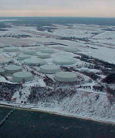
Strategically located petroleum bulk storage facility. The only deep water platform (64’ operating draft) on the U.S. East Coast
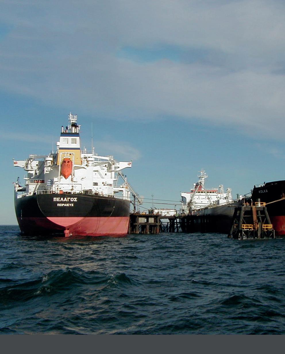
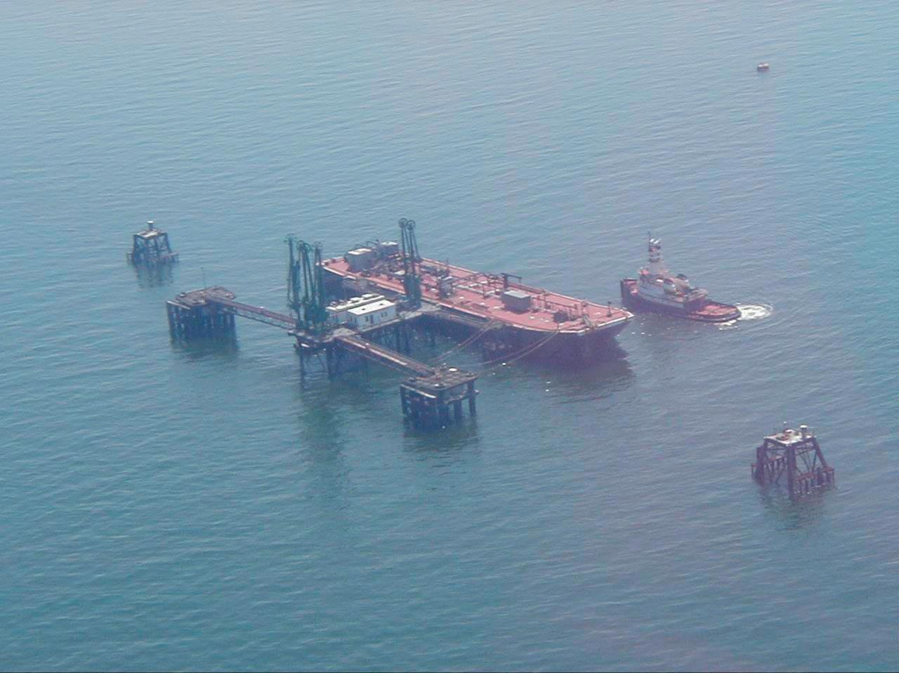
• 20 storage tanks 80 miles East of New York Harbor
• The only deep-water loading/ unloading platform on the U.S. East Coast.
• Total Storage Capacity of 5 Million Barrels
• Easy reloading for distribution of product to U.S., Canada and Europe

(631) 284-2010
stringent requirements for gasoline storage tanks, gasoline loading racks, and gasoline-service equipment. Also, the testing thresholds to determine whether a gasoline cargo tank is vapour-tight are revised.
The Clean Air Act specifies a three-year timeframe to reach compliance with revised Part 63 rules, so existing terminals must comply with the Subparts R and 6B changes before 8 May 2027.23 Performance tests for VCUs and initial performance evaluations for VRUs must be complete before that date. New terminals must comply upon start-up. By contrast, when Part 60 (NSPS) rules are revised, existing facilities come into compliance with the new rule only after the first time they are modified, or reconstructed, after the date on which the rule is proposed. As a summary, most changes to a facility that cause emissions to increase are considered a ‘modification,’ and most changes that cost more than 50% of the cost of an equivalent new facility are considered a ‘reconstruction.’24 There may therefore be some loading racks that are already subject to Subpart XXa, either to the loading rack standards or to the LDAR standards, due to having ‘modified’ or ‘reconstructed’ the loading rack or the gasoline-service equipment since 10 June 2022. Going forward, terminal operators should carefully consider the effects and schedules of capital projects affecting their loading racks, to assess if those projects will cause the racks to be subject to Subpart XXa’s stringent new standards.
Certain aspects of the revisions to 40 CFR Part 60, Subpart XX and 40 CFR Part 63, Subpart 6B merit further discussion.
Each of the final rules includes an LDAR instrument monitoring programme to detect leaks from equipment in gasoline service. None of the current rules for gasoline distribution facilities require instrument monitoring. An LDAR programme may apply already if an existing terminal’s project added equipment in gasoline service since 10 June 2022. At present, it is possible to interpret the rule to mean that it applies after addition of any de minimis number of valves or flanges to an existing gasoline terminal.25 Apart from ‘modifying’ or ‘reconstructing’ the collection of gasoline-service equipment under Subpart XXa, LDAR will apply to the equipment from 8 May 2027 under the other two subparts. The three subparts only differ in frequency of monitoring, as shown in Table 1.
The required programme includes two options. One option is to use EPA Method 21 to detect leaks, as is common at petroleum refineries or chemical plants. The other option is to use optical gas imaging (OGI) to detect leaks. OGI technology creates images of hydrocarbon gases, such as gasoline vapours. Both programmes require specialised equipment, as well as a detailed inventory of components in gasoline service.
First-time implementation of an instrument monitoring LDAR programme requires advance consideration of several factors, especially for terminals in remote locations. Inspection logs required under current rules must be replaced with detailed, individually identified components. A compliance tool must be developed or purchased to record component identifiers and monitoring results. A decision must also be made between selecting a contractor or training a terminal’s staff to provide routine monitoring. This decision would consider the availability of contractors and of monitoring equipment.
The final rules make substantial revisions to emission standards for loading racks and associated vapour control systems at gasoline distribution facilities, as Table 1 illustrates. Key changes include:
n Lower standards for many VCUs, regulated as ‘thermal oxidation systems’: emission standards for VCUs decrease under Subpart XXa and Subpart 6B. The current Subpart 6B specifies that bulk gasoline terminal loading racks with gasoline throughput of 250 000 gal./d or greater must reduce the emissions of TOC to less than or equal to 80 mg/l TOC.26 This standard will be reduced to 35 mg/l TOC. VCUs at loading racks under the new Subpart XXa must meet emission standards of 1 mg/l TOC (new loading rack) or 10 mg/l TOC (modified or reconstructed loading rack), compared with a prior Subpart XX standard of 35 mg/l TOC. The Subpart R standard of 10 mg/l TOC is unchanged.
n More stringent monitoring requirements for VCUs: in the section to follow, details of new VCU monitoring requirements are explained.
n Open flare standards: achieve at least 98% reduction in emissions of TOC by weight, and demonstrate this reduction using rules pulled from the refinery flare rules to Subpart XXa.27
n Vapour recovery system: when complying with any subpart using a VRU, emission standards are now expressed as parts per million by volume (ppmv) as propane, determined on a three-hour rolling average. Since prior subparts relied on a six-hour averaging period for performance testing, existing units should be assessed for suitability under a three-hour rolling average standard.
Monitoring a VCU for compliance with the new rules is perhaps their most challenging compliance aspect. While some VCUs were required to monitor firebox temperature under the pre-2024 Subpart R rule, most VCUs were regulated under the pre-2024 subpart 6B rule. This rule provided monitoring the presence of a pilot flame as an alternative to measuring the firebox temperature.28 Gasoline vapours readily combust in the presence of a flame.
Under the final rules, monitoring requirements for VCUs become much more restrictive. New loading racks built since 10 June 2022 will be subject to Part 60, Subpart XXa and must continuously monitor temperature.29 Loading racks subject to Subpart XXa due to modification or reconstruction after that date, as well as racks subject to Part 63, Subpart 6B and complying by 2027, have an additional option to monitor the NHV of the gases fed to the VCU.30 Such racks would follow rules for open flares at petroleum refineries in several respects.31 These monitoring options are challenging because each option is likely to result in substantial use of assist gas. For the temperature monitoring method, the final rules require determining a VCU temperature set point at the lowest three-hour average temperature during the emission performance test of the unit.32 By rule, the performance test involves a minimum amount of gasoline loaded.33 As gasoline vapours release heat when combusted, the performance test
VOL storage emissions standards are set to change in September 2024.
The market-leading, desktop-based program, that uses emission estimation procedures from AP-42 Chapter 7 to calculate emissions from floating- and fixed-roof tanks.
BREEZE ESP+
Highly-anticipated, cloud-based solution including all TankESP capabilities plus ability to calculate emissions from:
f Catch Pans
f Combustion Units
f Control Devices
f Equipment Leaks

f Line/Vessel Openings
f Loading Operations
f Sumps/Oil-Water Separators
f Vacuum Trucks
Now is the time to prepare for the proposed NSPS changes by investing in tank emissions calculations software today.
When it comes to tank emissions calculations, we have you covered!

time period naturally has bias toward higher temperature than time periods when gasoline and non-gasoline load rates vary with demand. In supporting documents to the final rule, the EPA asserts that during periods of lower temperature, the VCU may be operating in an overdilute manner, reducing its emission control effectiveness.34 In comments on the 2022 rule proposal, industry trade associations asserted that in fact, VCUs maintain high effectiveness at lower temperatures than would be expected during the emission performance test.35 In the final rule, the EPA retained the requirement to set a three-hour average temperature during the test. Therefore, terminals are obliged to maintain this temperature whenever gasoline is loaded. In that many terminals are not able to certify the prior load contents of a given truck’s cargo compartments, this requirement will apply to diesel loading. Accordingly, compliance will require substantial auxiliary fuel.
Some facilities use a VCU as a backup vapour control system to their primary vapour recovery system for when the primary vapour control system is down. If the backup VCU is required to combust additional auxiliary fuel to maintain the firebox temperature, operation of the backup vapour control system may become cost-prohibitive.
The EPA believes that small terminals, for which this requirement is cost-prohibitive, will elect the alternative option, to monitor the NHV and ‘dilution parameter’ (NHVdil) of the VCU.36 The rules require continuous compliance demonstration, either through continuous online assessment of waste vapour composition or NHV, or through continuously tracking the loading rack’s gasoline loading rate and gasoline-to-non-gasoline loading ratio.37 The EPA thereby requires terminals to demonstrate that waste vapours to the VCU maintain an NHV of 270 Btu/ft³, and NHVdil of 22 Btu/ft². Similar to the temperature option, these requirements require substantial use of assist gas if non-gasoline loading operations must be treated as gasoline loading due to unavailable information on prior truck loads.
Facility operators should begin to develop their compliance approaches for VCUs, whether serving as primary or backup controls. From the more limited options available in the rules, facilities should select a vapour control and compliance demonstration approach that achieves compliance in a cost-effective manner.
The final rules also reduce the duration of averaging periods for loading rack emission control devices, creating another potential challenge for facilities subject to the revised rules. For a thermal oxidation system other than a flare, the EPA requires that combustion zone temperature be maintained at or above the level determined during the performance test on a three-hour rolling average basis.38 Similarly, the EPA is finalising a three-hour rolling average monitoring period for the ppmv emission standards for vapour recovery systems. Prior to this rulemaking, the averaging period for performance testing for either type of control device was six hours.39 Changing from a six-hour to a three-hour rolling average impacts the perceived effectiveness of control devices.
In a VCU, actual firebox temperature is related to the volume of gasoline vapours combusted at a given time. At most facilities, loading activities do not occur at a uniform rate throughout the
day but are, rather, characterised by periods of higher gasoline demand followed by periods of lower gasoline demand. Decreasing the window for a rolling average temperature parameter, from six hours to three hours, means greater variability in the VCU temperature. Rises and falls in temperature due to varying gasoline vapour generation rates do not correlate with VCU effectiveness. However, operators now have a compliance need to stay above the required temperature minimum. This need might be met by adding assist gas, shortening periods of higher loading rates, or smoothing periods of peak and low demand. This compliance need could result in more waiting time for tank trucks or delays for delivering gasoline to customers.
In vapour recovery systems, a limit expressed as ppmv on a three-hour basis is more stringent than the same limit expressed on a six-hour basis. Facilities’ existing vapour recovery systems may need to be redesigned to be able to accommodate the final emission limits on a three-hour rolling average basis.
In the final rule, the EPA provided an alternative monitoring option for VRUs, for up to 240 hr/yr in periods when the VRU continuous emission monitoring system (CEMS) is offline for more than 15 minutes.40 The alternative involves establishing the quantity of liquid loaded, vacuum pressure, purge gas quantity, and duration of vacuum/purge cycle length over the prior 10 regeneration cycles of the VRU, and using these values as monitored operating parameter values during periods of CEMS downtime. In practice, the option is likely not workable for many terminals. The option would limit gasoline loading throughput, while the option is in use, to the minimum throughput in the past 10 regeneration cycles of the VRU. As that minimum throughput may be zero, the option is unpredictably unavailable in practice. The option may also impose unworkable values for the monitored parameters, as VRUs use CEMS data to tailor actual cycle length and operations when CEMS data is available. And, it is not typically necessary for a VRU to measure purge gas quantity for operations, so information on purge gas quantity is likely not available to most terminals. For these reasons, terminals should carefully examine whether the alternative monitoring option for VRUs is workable.
The EPA has finalised key changes to air emission standards for the gasoline distribution industry. The revisions include instrument monitoring LDAR requirements, revised monitoring requirements for storage vessels, and substantial changes to emission standards and compliance demonstration methods for loading racks. The new standards may require affected facilities to undertake capital projects, to implement new compliance demonstration programmes, or to conduct internal feasibility studies for compliance planning purposes. Gasoline distribution facilities should begin developing compliance strategies for the revised rules, especially as NSPS Subpart XXa rules apply to facilities modified after 10 June 2022.
Note
For a full list of references, please visit: www.tanksterminals.com/product-news/01072024/ final-revisions-to-industry-air-regulations--references
Bernat Sala, Tecam, Spain, explores the necessity of gas venting emissions treatment and vapour recovery technology in tank storage terminals.
Tank terminals are critical nodes in the global supply chain for hydrocarbons and other bulk liquids. These facilities are responsible for the storage and transfer of vast quantities of hydrocarbons, containing volatile organic compounds (VOCs), which can lead to significant environmental challenges if not properly managed.
Emissions from tank terminals can contribute to air pollution, pose health risks, and lead to regulatory non-compliance. To address these challenges, emission treatment technologies and vapour recovery units (VRUs) have become essential for tank terminal operations.
Tank terminals face several environmental challenges due to the nature of the substances they store. Hydrocarbons, for instance, are highly volatile and can easily vaporise into the atmosphere, leading to VOC emissions. These emissions are not only harmful to the environment but can also present significant health risks to workers and nearby communities. Furthermore, the release of VOCs can result in substantial economic losses due to the evaporation of valuable products.
The primary sources of emissions at tank terminals include:
n Tank breathing: the natural evaporation of liquids during storage, particularly when temperatures fluctuate.
n Tank filling and emptying: the displacement of vapours as tanks are filled or emptied.
n Loading and unloading operations: the transfer of liquids between storage tanks and transport vehicles.
Emissions treatment technology plays a crucial role in mitigating the environmental impact of tank terminals. These technologies are designed to capture, control, and eliminate the emissions so that they are not released into the atmosphere.
Some of the key emissions treatment technologies include:
n Thermal oxidisers: these systems use high temperatures to oxidise VOCs into less harmful substances such as carbon dioxide and water vapour. They are highly effective but can be energy-intensive.
n Catalytic oxidisers: similar to thermal oxidisers, these systems use a catalyst to lower the temperature required for oxidation, making them more energy-efficient.
n Activated carbon adsorption: this technology involves passing emissions through activated carbon, which adsorbs VOCs onto its surface. Once saturated, the carbon can be regenerated or replaced.
n VRUs: they are specifically designed to capture and recover vapours that would otherwise be lost to the atmosphere. VRUs are essential for tank terminals as they not only reduce emissions but also allow for the recovery of valuable hydrocarbons.
n Condensation systems: these systems cool vapours to condense them back into liquid form. They are highly effective for high-concentration VOC streams and can recover a significant portion of the hydrocarbons.
n Absorption systems: in these systems, vapours are passed through a liquid solvent that absorbs the VOCs. The solvent is then regenerated to recover the hydrocarbons.
n Adsorption systems: similar to emissions treatment, vapours are passed through an adsorbent material such as activated carbon. The adsorbent can then be regenerated to recover the hydrocarbons.
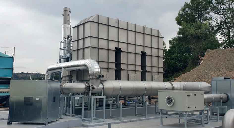
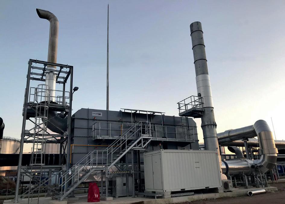
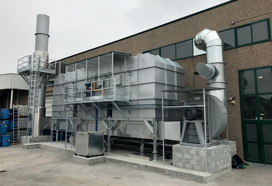
Regenerative thermal oxidation (RTO) is currently the most suitable technology for gas venting emissions abatement, and is one of the solutions recommended for that goal by the European Commission in its reference document on best available techniques (BREF) on emissions from storage, together with technologies such as adsorption, absorption, condensation, and membrane separation.
The implementation of emissions treatment technology and VRUs in tank terminals offers several significant benefits.
Firstly, it ensures environmental compliance by adhering to stringent regulations, thereby avoiding fines and penalties. This compliance is crucial for maintaining operational legitimacy and preventing legal and financial repercussions.
Secondly, these technologies protect the health and safety of workers and nearby communities. By effectively controlling and reducing harmful emissions, the risk of respiratory issues and other health problems associated with VOC exposure is significantly minimised. This not only fosters a safer working environment but also enhances the quality of life for those living in proximity to the terminals.
Thirdly, vapour recovery leads to substantial economic efficiency by reducing product losses. By capturing and reprocessing vapours, tank terminals can recover valuable hydrocarbons that would otherwise be lost to the atmosphere. This recovery translates directly into cost savings and improved profitability for the terminal operators.
Lastly, the adoption of these technologies reflects a strong sense of corporate responsibility. Companies that invest in advanced emissions control and recovery systems demonstrate their commitment to environmental stewardship. This commitment enhances the company’s reputation as an environmentally responsible entity, which can lead to better stakeholder relationships, customer loyalty, and competitive advantage in the market.
Koole Tankstorage Minerals (KTM) needed to eliminate the vapours and odours generated while barge and ship offloading for tank farm filling purposes with fuel oil, vacuum gasoil, and class-3 blend components. These vapours contained highly polluting particles, mainly: VOC, CO, SOx, NOx, MVP2, and PM10.
Once the problem and all its variables were analysed, Tecam proposed a custom-made RTO as the optimal solution taking into account the volume, nature, and characteristics of the emitted vapours:
n Polluted air to be treated: 40 000 Nm³/h of air flow.
n Low concentration of VOCs.
n VOC 2g C/Nm³.
n Very variable air flows.
During this RTO equipment life cycle, more than 13 860 t of VOCs will be eliminated and not emitted into the atmosphere, providing a safe, clean solution for tank terminals in regards to emissions abatement.
As the tank storage sector continues to grow, the need for effective emissions treatment and vapour recovery technology becomes increasingly critical. By implementing these technologies, tank terminals can mitigate their environmental impact, ensure regulatory compliance, and recover valuable hydrocarbons.
Tecam is committed to providing innovative and efficient solutions to help tank terminals achieve these goals and maintain sustainable operations.
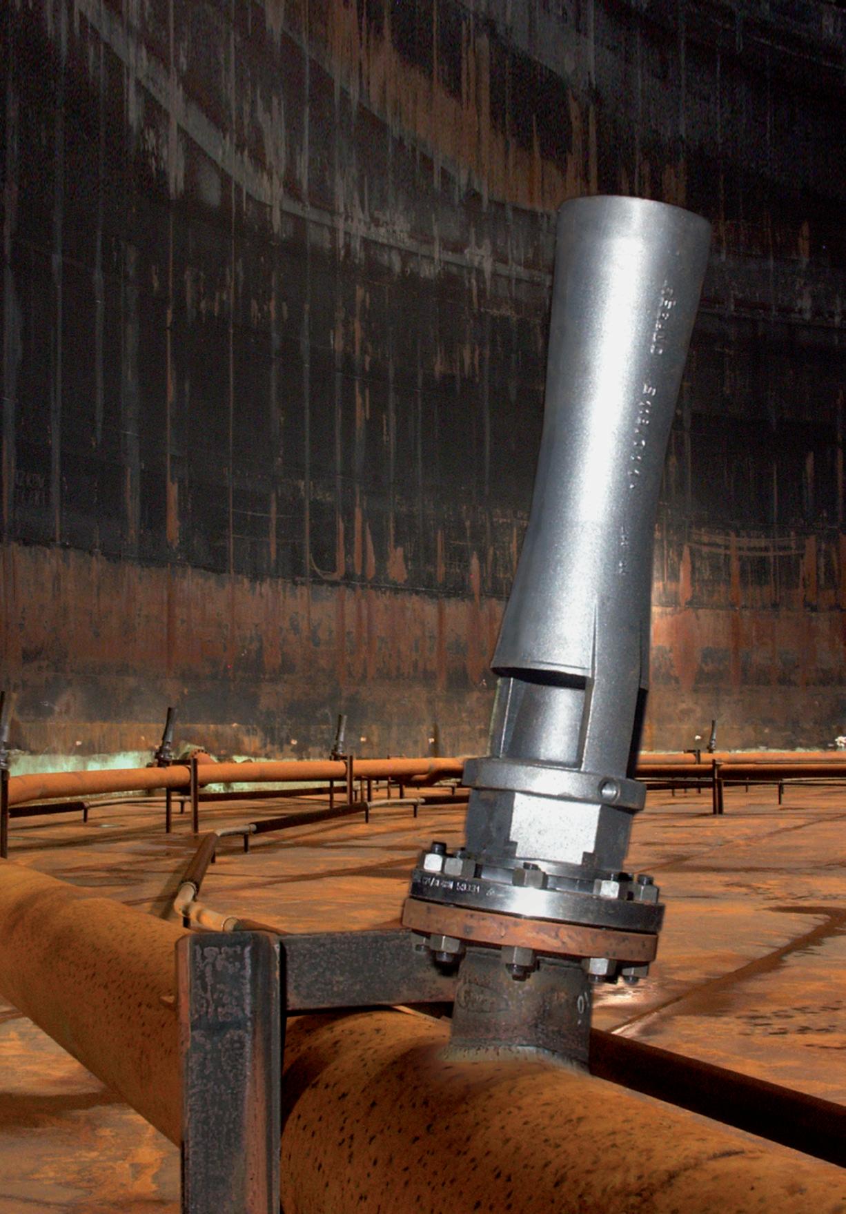
Ideally arranged, the proper amount of Jet Mixers produces a three-dimensional flow that mixes the entire contents without creating a rotating motion in the tank. Delivering high efficiency, operational safety, resistance to fouling and little wear & tear thanks to its simple and robust construction Download our catalog





www.accelevents.com/e/ghc2024


Thomas Kemme, AMETEK Level Measurement Solutions, USA,
discusses how traditional level measurement techniques can be enhanced.
For generations, process industries have relied upon traditional level measurement techniques often stemming from mechanical principles. And why not? Trusted, reliable techniques that have proven themselves through decades of field use in the most demanding applications deserve user confidence. Traditional technologies include displacer level transmitters and sight glass level gauges, found in large installed bases throughout the energy sector to this day. However, significant improvements have been made to innovate around these core principles to create something far more efficient for processes while decreasing total cost of ownership.
Starting with buoyancy-based products, floats and displacers have long held their place in demanding applications including high pressures, temperatures, and corrosive environments. Many tank farm and terminal operators deploy displacer switches on storage tanks as fail-safes for
hydrocarbon liquid overfill prevention and floating roof detection due to their versatility and durability in these applications earned through decades of service. With a similar operating principle, displacer switches are transformed into continuous transmitters using torque tubes and linear variable differential transformer (LVDT) based technologies. These transmitters provide users with continuous visibility into their desired level span, most often
through measuring an analogue output (current/4-20 mA) proportional to their 0 - 100% level range.
Torque tubes represent the majority of displacer transmitters found in the field. While the traditional torque tube uses a torsion bar that rotates relative to the weight of the displacer in liquid to correspond to a level change, a more seamless design was innovated using an LVDT and range spring combination. The latter design has an LVDT core that moves as the spring is unloaded, which occurs as the liquid level covers the displacer. This core movement induces voltages across the LVDT secondary windings located in the transmitter enclosure and these voltages are then converted to a level output measured through the 4-20 mA current loop. The technology can be top mounted directly into the vessel or installed into an external chamber mounted to the outside of the vessel.
Compared to torque tubes, the LVDT/range spring technology has proven to be more resistant to vibration, providing a more stable output resulting in better linearity and repeatability. Other factors contributing to the success of LVDT/range spring displacer transmitters include the linear structure of the physical design as opposed to the rotational torque tube. This design creates multiple benefits, including reduced long-term maintenance costs; a smaller installation footprint for facilities with confined spaces; and the ability for the transmitter to be removed without de-pressurising the tank.
The last factor, being able to perform maintenance or replacement of the transmitter without shutting down the process, results in increased uptime and plant profitability. The transmitter itself is an important element in the system, capable of advanced diagnostics while providing extreme ease-of-use through an intuitive user interface with quick-start menus to get processes up and running in a timely fashion. Make no mistake, these old displacers are ‘smart’ transmitters built upon years of feedback and experience in the field.
Another basic, yet important, traditional method for level measurement has been through visual indication of the liquid level. Providing visual indication becomes more complex in process industries where extreme properties and corrosive environments come into play. Nevertheless, visually inspecting the level is a technique that is still often used during walk-throughs, process start-ups, or to provide a degree of redundancy alongside other level instrumentation in applications such as storage tanks, separators, and boilers.

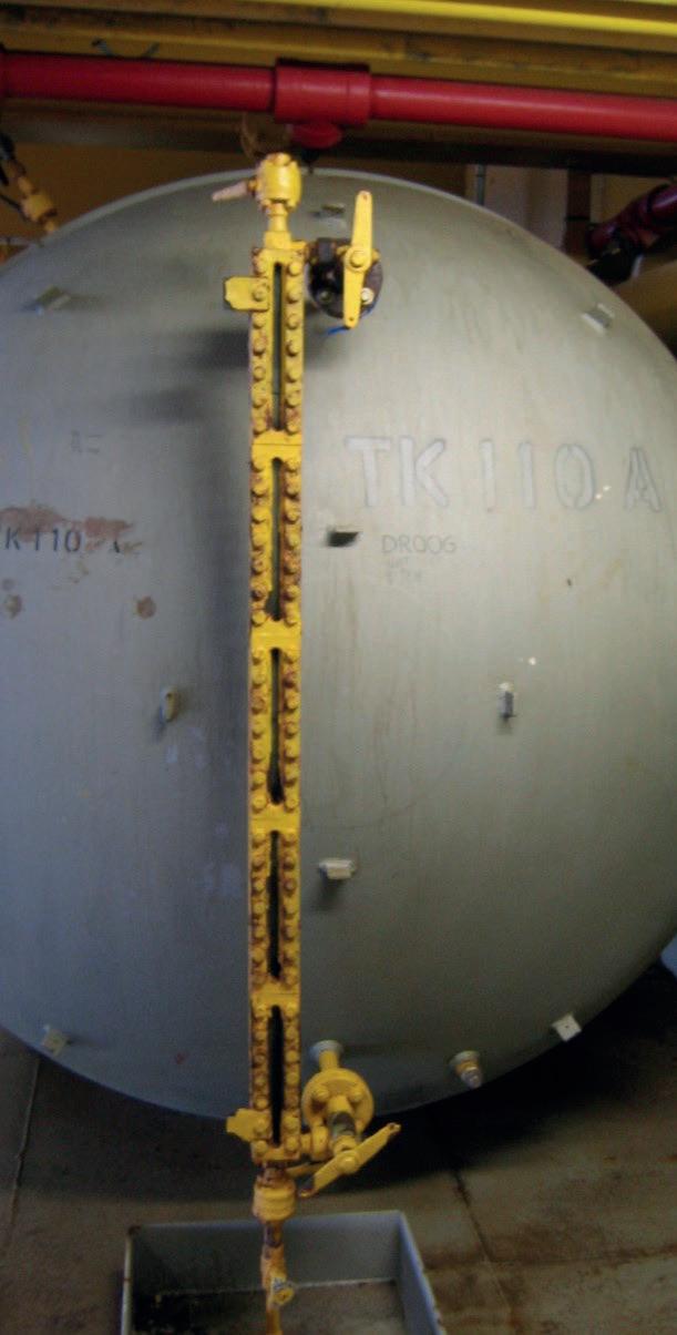
Whether it be petroleum refineries or power plants, sight glass gauges are the most prevalent method of visual indication. However, users familiar with sight glass gauges may encounter problems such as breakage, leaks, or bursting, particularly at high pressures
and temperatures. In addition, the visibility of sight glasses can be poor and often affected by moisture and corrosion.
An alternative technology used in place of sight glasses and now commonly specified in greenfield and brownfield projects is the magnetic level indicator (MLI) or magnetic level gauge. MLIs utilise a magnetised float inside of a chamber, which is isolated from a visual indicator and mounted to the outside of the process or storage vessel. The indicator has enclosed flags or a shuttle that is magnetically coupled to the magnets inside the float. The float follows the liquid level inside of the chamber, providing a clear representation of the liquid level as the indicator flags flip or the shuttle moves with the float.

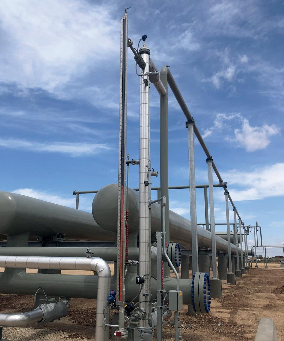
One of the biggest differentiators with MLIs from sight glasses is the isolation of the visual indicator from the chamber and therefore the application media, eliminating the ramifications of these fluids coming into direct contact with the indicator. The viewing window of the indicator is often produced using a polycarbonate, providing better shatter/impact resistance compared to glass as well as reduced UV sunlight exposure. There will be process temperature limitations when using polycarbonate, where glass is still required at extreme high temperatures. Other parts of the MLI can be provided in various plastic constructions for chemical compatibility purposes including the chambers and floats. When adding up these differences and evaluating typical repair costs of sight glass gauges, including the seals/gaskets, glass kits and labour for removal and replacement, it amounts to thousands of dollars in maintenance compared to MLIs. This does not include the negative impact to plant revenue and profitability due to process downtime during sight glass repair.
An additional benefit of MLIs is the ease of implementing level transmitters or switches if an output proportional to the liquid level is required in addition to the visual indication. This can be beneficial as a measure of redundancy or if it is simply desirable to output the tank levels into a programmable logic controller (PLC) or distributed control system (DCS). The most common level transmitters supplied through MLI designs are guided wave radar (GWR) and magnetostrictive.
Both GWR and magnetostrictive technologies can be deployed using a dual chamber design, which has the advantage of isolating the level transmitter from the MLI if maintenance must be performed on the transmitter. Alternatively, single chamber designs are available which allows both visual indication and continuous level output. This can be accomplished by externally mounting a magnetostrictive probe to the outside of an MLI chamber (utilising the same float for measurement) or installing a GWR probe directly into the chamber. In the case of GWR, a probe is installed parallel to the MLI float and separated by a baffle plate inside the chamber. The use of GWR provides an additional degree of redundancy, as the GWR transmitter operates independently from the float (if the float gets stuck or damaged) and conversely there is no effect on the MLI if the level transmitter signal becomes lost.
Alternatively, or in addition to level transmitters, level switches can be clamped to the side of the MLI or directly installed into the chamber (also operating off the float) or installed into the chamber using ultrasonic switches. Of course, switches provide an on/off detection for low and/or high levels as opposed to continuous level measurement from a transmitter.
The prevalence of these mechanical-based technologies still in use today prove not only their reliability at the outset, but their continued refinement through the years to keep them in a competitive position against many newer level instrumentation technologies. And based on the comfort and familiarity they provide users all over the world in some of the most demanding process industry applications, chances are the industry will continue to see these instruments specified in the next generation of industrial facilities to come.
Gregory Tischler, VEGA Americas, USA, examines how a tank farm can benefit from the installation of modern radar level sensor solutions.
Tank farms have long employed level measurement solutions to ensure optimal operations. One of the premier technologies used in these applications is radar. Radar sensors that are used for tank level measurement are mounted at the top of the tank, pointed downwards. These sensors operate by transmitting electromagnetic energy to the surface of the material being measured. The electromagnetic energy is reflected off the surface and returns to the radar. The time of flight of the

electromagnetic energy is used to determine the distance to the surface. This distance measurement is converted to a level measurement by the sensor’s electronics.
A major operator of a large-scale tank farm faced significant challenges in preventing overfills. Its existing methods of obtaining measurements – float systems and tilt switches–were prone to inaccuracies and mechanical failure, requiring

frequent maintenance and leading to operational inefficiencies and potential safety hazards. Seeking a more reliable solution, the operator explored the potential of using advanced radar level measurement technology.
Radar level measurement in the tank farm can be separated into two broad categories: tank gauging systems and overfill prevention systems.
Initially, the tank farm operator in this case study integrated radar sensors into its tank gauging systems. For nearly 50 years, radar has been used as a means to provide level measurement for tank gauging systems. These custody transfer radars are extremely accurate (+/- 0.5mm). Furthermore, some form of digital communication is usually employed to ensure that accuracy is not lost during the transmission of the level information.
In recent years, radar level sensors have experienced an increase in usage as part of overfill prevention systems.
These sensors are not affected by changing process conditions; changes in temperature, pressure, or product density do not affect the radar’s ability to detect the overall level of the material in the tank.
Another major benefit of using radar sensors in overfill prevention systems is that they are solid state devices. There are no moving parts, and there is no maintenance or calibration required. Once a sensor is installed, the operator does not have to do anything to keep it running reliably.
After learning of the additional benefits of radar, the tank farm operator expanded its use of sensors beyond tank gauging and into the overfill prevention systems. One standout feature for the operator was the active nature of radar sensors. With the radar sensors constantly measuring the level, the sensors’ output could be compared with inventory management sensors, allowing the client to monitor performance continuously. Discrepancies between sensors could indicate potential issues, giving operators ample warning to address problems before an overfill condition occurred.
Radar sensors constantly run diagnostics and monitor their own performance. If proof tests are required, radar sensors can be tested by remotely activating a function test. In this scenario, the operator sends a command to the radar sensor to perform its diagnostic function. The tool used to send these commands, usually a computer connected to the sensor via a form of digital communication (HART, Modbus, etc.), will produce a report documenting the results of the test.
Radar used for overfill prevention has the added benefit of mounting capability; it can be mounted on the vessel and deployed in a variety of methods. For example, radar level measurement sensors are typically mounted on the roof of the tank and measure the liquid directly below. In tank farms, it is also common for radar level sensors to be mounted over a floating roof or measuring the liquid surface in a stilling well.
The aforementioned tank farm operator deployed radar sensors in various configurations; one of these configurations was floating roof mounting. When mounted over a floating roof, a radar sensor actually measures the surface of the roof as it travels up and down with the surface of the liquid. The metal roof is highly reflective, thus returning a high amount of radar energy back to the sensor. The construction can be an internal or external floating roof. When it is an external floating roof, the radar sensor is mounted in a fixed location on a bracket, usually near the wall of the tank that is easily accessible for maintenance.
On a tank with an internal floating roof, the mounting is the same as when measuring the liquid directly on a fixed roof tank. The difference is that the radar energy is reflected off the roof instead of the liquid. If a casual observer were to see it from outside of the tank, they may not know if the radar sensor was measuring the liquid directly or measuring the metal roof.
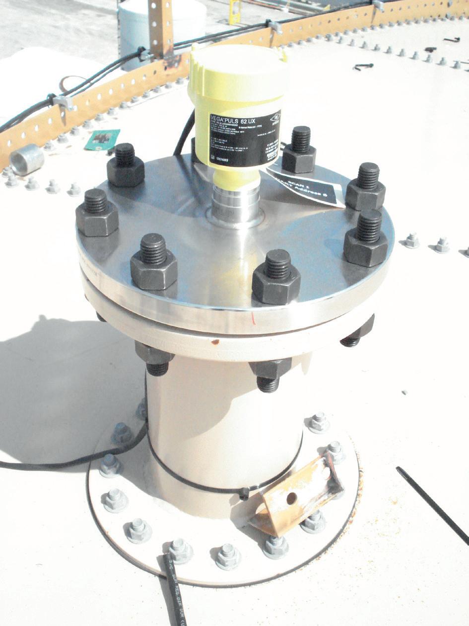
Measurement in a stilling well is another common method of measuring liquid level in tank farms. A stilling well in a tank farm is usually constructed using a pipe that is between 4 in. and 10 in. dia., with 8 in. being the most common size. The stilling well is permanently installed in the tank, encompassing the entire measurement range. The measurement takes place entirely within the confines of the stilling well. Stilling wells can be on both fixed roof and floating roof tanks. The advantage to using a stilling well to take a measurement is that nothing outside of the stilling well can impact the measurement signal.
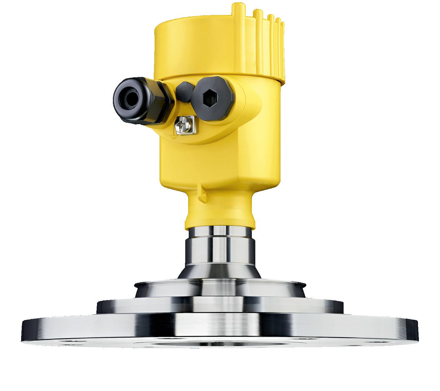
Most modern radar sensors utilise frequency modulated continuous wave technology (FMCW) for making the distance measurement to the product surface. FMCW technology can be both low-powered and very accurate. Alternatively, pulse radar has been used in the past, but manufacturers of radar level sensors have not introduced a radar that employs pulse technology in more than five years. Leading suppliers of radar level sensors are utilising FMCW technology.
The Federal Communications Commission (FCC), US, has allocated three frequency bands for Tank Level Probing Radar: C-band (5.925 – 7.250 GHz), K-band (24.05 – 29.00 GHz), and W-band (75 – 85 GHz). All three have been used throughout the years in tank farms and are still used today.
The W-band offers some unique differences compared to C-band and K-band. For radar signal transmissions using the same size antenna, the higher the frequency, the smaller the beam angle. 80 GHz radar (W-band) has the narrowest beam angle of the three available frequencies. This means that it focuses the most energy directly below the antenna onto the surface of the product being measured. The result is that, with all things being equal, W-band receives the strongest and most reliable measurement signal when compared to the other frequencies.
A narrow beam also translates to more choices of mounting location for the radar sensor. It can be closer to the sidewall, avoiding false signals from weld seams or other mechanical obstruction along the wall. It can also be recessed in a tall mounting nozzle when measuring directly to the liquid surface or to the floating roof.
Another advantage of using the W-band frequency range is that 80 GHz radars can be offered with smaller antennas than the other frequencies. For example, a 3 in. dia. antenna (either a horn or lens antenna) from a K-band radar sensor has the same beam angle as a W-band radar sensor with a 1 in. dia. antenna.
The result is that smaller antenna systems can be used for W-band radar sensors, making them easier to install. The tank farm operator in this scenario found that this afforded them the ability to be creative in how they deployed the sensors. They could mount radar sensors on the same process connection as other devices, such as a sounding or sampling port, without degrading performance.
80 GHz radar sensors can be small enough that it is possible to mount multiple on the same process connection, with process connections as small as a 6 in. dia. flange. This allows for redundancy while utilising a single process connection. Alternatively, instead of using two radar sensors, it is possible to have a sounding or sampling port and a single radar sensor on a single process connection.
The use of radar level sensors for overfill prevention in tank farms offers numerous benefits, including reliability, accuracy, and versatility in deployment. With advancements in 80 GHz radar technology, operators can achieve more precise measurements and greater flexibility in sensor installation. As the industry continues to evolve, radar level sensors remain a crucial component in ensuring the safe and efficient operation of tank farms.
As for the tank farm operator featured in this article, it continues to reap numerous benefits through the use of radar level measurement. Radar is low maintenance: there are no moving parts, and the sensors do not need to be recalibrated. The operator no longer has to work with the frequent inaccuracies of floats. Radar is always active and performing diagnostics, informing the user of any issues in the system. With 80 GHz radar, the tank farm operator realises safer, more reliable, and more efficient processes.

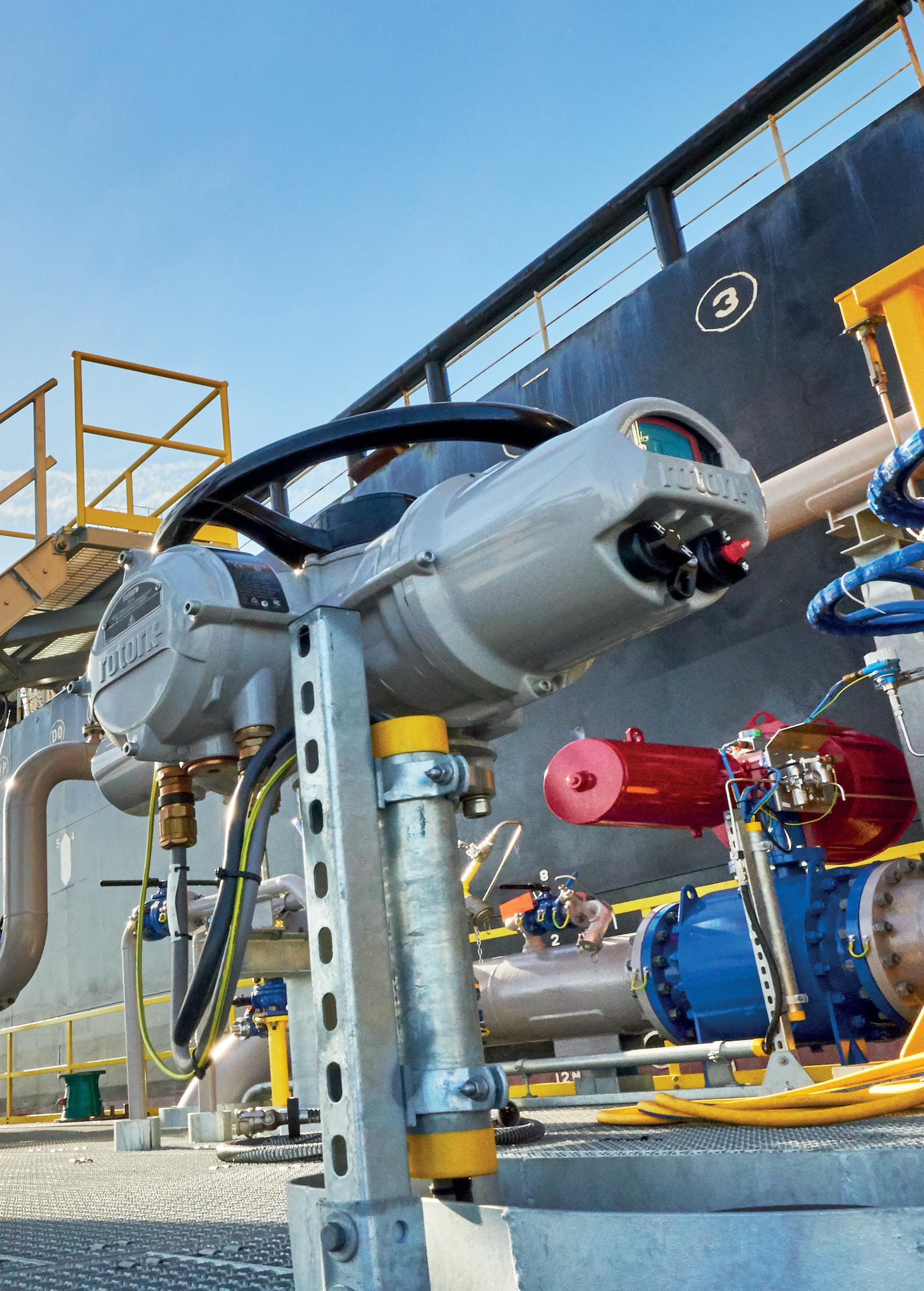
Dave Godfrey, Rotork, UK, explains why maintaining actuators should be a top priority for terminal operators.
Hundreds of intelligent electric actuators manage the flow of liquids and gases at the Pengerang Deepwater Petroleum Terminal in Malaysia. Like many oil and gas terminals across the world, it relies on precise electric actuation to ensure safety and efficient operations while limiting environmental impact.
Optimum flow performance is essential and Rotork’s PakscanTM system controls hundreds of IQ intelligent actuators at the site on the Johor Peninsular. The system can support the full automation of a complex plant and link up 240 actuators on a single two-wire loop. It also enables operators to override automatic settings and operate any individual actuator if the need arises, to control flows and levels.
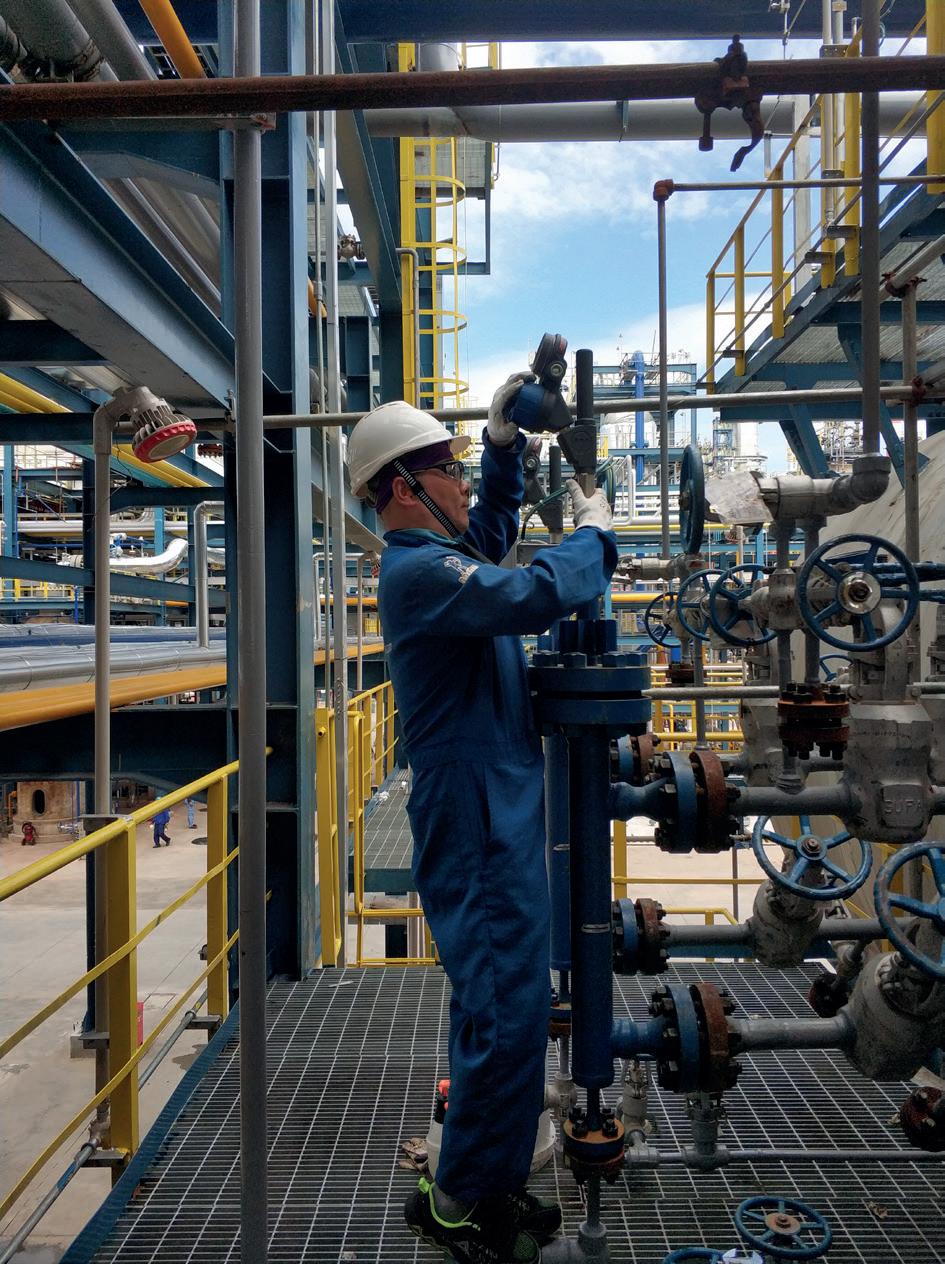
The system is designed to work with Rotork actuation products and is backed up by a worldwide service and support network. Rotork Site Services (RSS) provides field support at Pengerang for repairs, commissioning, upgrades, and maintenance. It is part of a maintenance option for customers that ranges from basic repairs to a premium package for actuators on critical processes.
Tank terminals like Pengerang house some of the greatest concentrations of actuators anywhere in the industry and these must be maintained to avoid expensive downtime. The aftermarket offering from RSS addresses the need to monitor and maintain this critical equipment. It includes a lifetime management service that proactively maintains actuators with the aim of reducing downtime and keeping tanks in optimum operational condition.
Engineers work with companies to consider each actuator and the likely consequences if they were to fail. These engineers aim to understand which would be the costliest, cause the most problems or the most severe process interruption. In a facility with 100 actuators that might well come down to just 10 that require the highest level of maintenance to avoid serious impacts if they were to fail.
One customer operating in the Asia Pacific region has a single actuator on a valve that is so highly critical, if it were to fail it would cost US$1 million per day in downtime.
However, not every actuator would cause a serious problem if it failed. As such, a tiered approach to maintenance, offering varied levels of cover, may be appropriate. For instance, companies can choose a premium package for actuators controlling their most critical processes and either a basic or standard package for less hazardous situations. While under the basic package engineers visit a terminal to inspect the actuators, under the premium offering they visit more frequently, take the terminal covers off to inspect
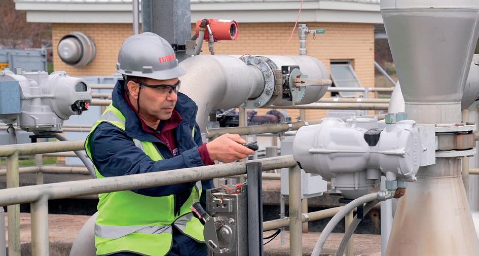
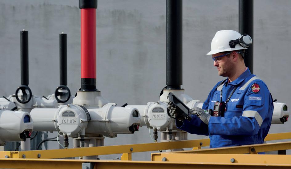
the internal workings of the actuators and change seals, oil, and parts as required. This can be combined with intelligent asset management where data is collected on things like vibration, temperature, torque, number of starts, and whether the unit has lost power.
This data is fed into an algorithm which enables engineers to assess the health of an actuator and make recommendations around maintenance, helping to head off any failure and potential downtime. As industries move increasingly towards electrification, intelligent asset management is linked to alternative ranges and types of electric actuators, which are fitted with data loggers.
RSS can also provide a range of options for customers that do not want an ongoing service contract. Field service engineers are available around the world to visit sites and fix problems and companies can also send their actuators to workshops to be repaired. There are also upgrade services that enable terminals to upgrade to newer and better actuators and a valve automation service where engineers can provide customers with motor operated valves to install on pipelines.
The rise of electric actuation delivers greater precision, efficiencies, and environmental performance. Under its service contracts, Rotork takes a proactive approach to lifecycle management, monitoring and maintaining actuators as they age and helping customers plan years in advance for the cost of replacements.
At industrial sites, it ranks each actuator at one of four stages: preferred product, supported product, mature product, or obsolete product. If a site has only preferred products, then spares are available and engineers have the knowledge and experience to repair and service them. But it is also important to help terminals to manage older actuators through its lifecycle management and obsolescence approach. If some products are obsolete, spares may not be available and this lack of spares means old actuators might simply have to be replaced if something goes wrong.
But if there are 100 actuators on a site that are all considered obsolete, they may still be working well and may continue to operate effectively for another 10 years. If any become unavailable, however, instead of a less costly repair they could require replacement, which would come at a greater cost – if 10 fail at the same time that can be costly.
While obsolete actuators are not normally taken into service contracts, Rotork’s engineers do continue to support customers with all of their assets and seek to remain a partner regardless of the asset and its age.
At London’s Gatwick Airport, GASHCo, one of the main fuel tank farms, has been using Rotork products for over 30 years. The actuators installed on the site are used on the fuel hydrants housed at the airport. The RSS team carried out an obsolescence survey and identified the older equipment.
Gatwick was alerted that in the event of a failure or breakdown, the required spare parts may not be available

for the obsolete actuators. Due to the risk of unplanned downtime, Gatwick decided to upgrade 24 actuators and add these to the existing maintenance agreement.
The upgrades to the IQ3 actuators at Gatwick are intended to maximise uptime and increase reliability while reducing operational costs. They have the capability to capture performance data through integrated data loggers, display accurate position and torque sensing, and include integral controls. The actuators have a low whole-life cost, and their high degrees of reliability mean a reduced likelihood of any interruption to operations.
Rotork is the original equipment manufacturer of some of the industry’s most widely used actuation solutions and can provide important ongoing servicing and maintenance. When India’s Netaji Subhas Chandra Bose International Airport upgraded to intelligent IQ3 actuators at its fuel stations, for example, it signed a service plan as part of Rotork’s Reliability Services Programme.
But even if a company has not taken out a maintenance contract, Rotork engineers are available to fix problems. RSS engineers are based all around the world and can be called upon to repair actuators if something goes wrong. These engines have advanced diagnostic tools and access to the company’s engineering resources, including all its back data. Moreover, when they assess a Rotork product they not only have all the knowledge and
data themselves but also have the support of the entire company.
Failing to maintain flow control equipment can have serious consequences. When the UK’s Buncefield oil storage terminal exploded in 2005 it was said to be the biggest blast in Europe since the Second World War. The disaster was caused by faulty equipment used to monitor the flow of petrol entering a tank and is a stark reminder of the need for a strict maintenance regime in severe service applications.
The tank, which had a capacity of 6 million l, was being filled with unleaded petrol when the automatic tank gauging system, designed to measure the rising level of petrol, failed, preventing alarms from working that would have alerted operators to the danger. The tank soon began to overflow, and significant loss of life was only avoided because the explosion occurred on a Sunday when the site was largely deserted.
Actuators manage the flow of hazardous liquids and gases in processes all over the world. Maintaining them properly can prevent serious damage to equipment, expensive shutdowns, and protect lives.
Tank terminals are the lifeblood of modern society, providing the fuel for everything from industry to transport. Intelligent electric actuators can play a key role in their successful operation and maintaining this vital equipment is essential.













Ted Huck, Matcor, proposes how vapour corrosion inhibitors (VCIs) can be used to combat corrosion damage on tank bottoms.
Large diameter aboveground storage tanks (ASTs) are typically built on top of a sand or soil prepared foundation with a concrete ring wall around the perimeter of the tank. During construction, the steel tank bottom plates are placed on the prepared foundation and welded to form a single tank bottom. The underside of these plates are subject to soil side corrosion. For tanks containing hydrocarbons or other hazardous materials, cathodic protection (CP) combined
with a secondary containment liner is usually required to prevent corrosion and release of product into the environment – in the US those regulations are administered by the Department of Transportation’s Pipelines and Hazardous Materials Safety Administration (PHMSA). While CP has proven to be quite effective at preventing soil side corrosion, these systems are not perfect, have some limitations, and they have a finite service life. One of the exciting new technologies that
has emerged to help prevent exterior tank bottom corrosion is the use of vapour corrosion inhibitors (VCIs). This article will discuss the use of this technology for protecting AST tank bottoms.
CP has a good track record for protecting the external bottom of ASTs. This is recognised by the regulatory bodies that mandate it and by industry standards from organisations such as the American Petroleum institute (API), American Water Works Association (AWWA), and Association for Materials Protection and Performance (AMPP) that all have detailed specifications discussing the appropriate use of CP for this purpose. There are, however, limitations to CP. Some of the key limitations include:
n Poor soil side contact – CP only works when the tank bottom is in intimate contact with the sand/soil foundation. If there are bulges in the tank bottom plates, or if the tank flexes when empty or only partially full, or if the sand bottom foundation is improperly compacted leaving voids, then CP would not be able to protect the tank bottom plate that is not in contact with the sand/soil.
n Poor choice of sand/soil padding material – the choice of sand/soil bedding materials can have an impact on the performance of CP. This is especially true with the use of sand mixed with oil or asphaltic material and some clay materials which can impede the consistent distribution of current along the tank bottoms.
n Sumps and drains – sumps and drains installed after the initial foundation compaction may create a localised area adjacent to the sump or drain with poor compaction leading to unprotected areas around the sump. In some cases, the CP system around the sump or drain can be damaged during the installation and this can lead to areas of poor CP current distribution.
n Out of service – most AST CP systems are impressed current systems and require a properly adjusted and maintained power supply and regular testing. If the
power supply is not operating (tripped circuit breaker, lightning strike, someone turns it off, etc.), the tank is not protected. Over time, anodes deplete and reach the end of their useful service life and occasionally systems fail prematurely. For tank CP systems that are directly between a high-density polyethylene (HDPE) secondary containment liner and the tank bottom, a failed CP system cannot be accessed for repair or replacement without taking the tank out of service and replacing the tank bottom.
VCIs are chemestries that slowly release a corrosion-preventative compound into the sand/soil pad. The VCI compound vaporises and diffuses throughout the tank bottom over time. The vapour molecules absorb to the metal tank bottom and suppress the corrosion reaction. This formation of absorbed molecules with sufficient concentration creates a protective barrier and with sufficient VCI and time this barrier spreads across the entire tank bottom, even to those areas not in intimate contact with the sand/soil. Some published studies have indicated that the time required to reach full diffusion could take as long as 12 months depending on the tank size, the VCI material formulation, the location, means and quantity of VCI material being installed, and other factors.
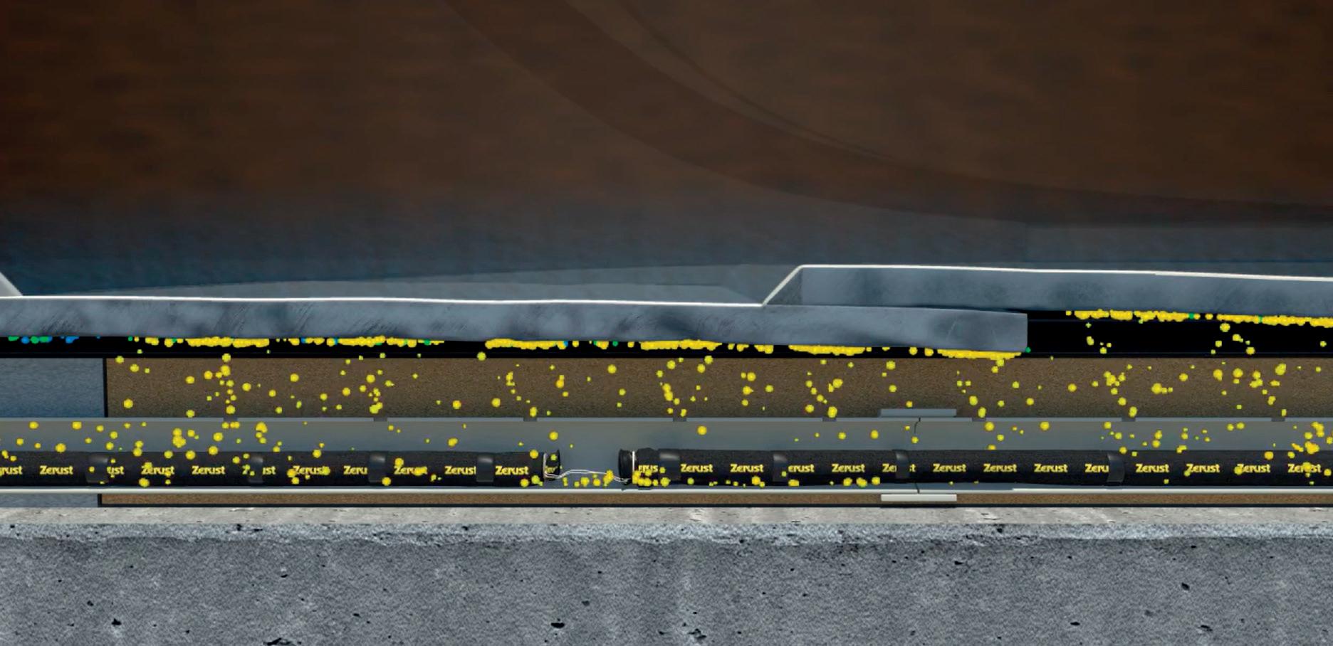
The VCI material is available in a wide range of delivery methods with the most common being a solid powder form or a mixed slurry liquid form. For new construction tanks or for installation in the interstitial space between two tank bottoms during a tank bottom replacement project, the VCI can be applied in a powder format, often installed in mesh bags inside PVC tubes that allow for a slow release of material. The use of powder installed in bags placed directly in the sand/soil should be avoided as the bags can leave a void space as the material volatises and there is no means for replenishment. Installing PVC tubes allows for future replenishment and does not cause voids in the sand/soil foundation. For existing tanks, the VCI material can be injected through existing leak detection ports as a liquid slurry, and if leak detection ports are not present, injection ports can be installed to facilitate the introduction of the VCI material under the tank. VCI material can also be installed using a chime seal flood by removing the chime seal, installing PVC piping and ports
We understand how you need to reduce complexities at your plant.
You strengthen your plant’s safety, productivity and availability with innovations and resources.

Endress+Hauser helps you to improve your processes:
• With the largest portfolio of safety instruments that comply with international regulations
• With applied technologies and people who have extensive industry application know-how
• With access to accurate and traceable information
Do you want to learn more?
www.endress.com/oil-gas
for introducing the material under the chime. After installation, the chime seal is restored.
It is important when applying VCI materials to consult with the manufacturer regarding the specific application and the quantity of material to be applied. Achieving an appropriate concentration of vapour molecules distributed over the entire surface to be protected is critical to the effectiveness of the application and in assuring that the system has a reasonable service life before reapplication of new VCI material is required.
CP system performance can be directly measured by monitoring the change in electrical potential of the tank bottom resulting from the application of current to the surface of the structure. For VCI applications, there is no means of directly measuring the impact of the vapour molecule absorption onto the surface of the tank bottom structure being protected. To address this, indirect measurements can be taken using ER probes to provide an instantaneous corrosion rate reading.
ER probes measure corrosion and corrosion rates as an increase in electrical resistance over time for a steel element in the probe face. The increase in electrical resistance is proportional to the accumulated corrosion of the probe element over the exposure period. The liberal use of ER probes placed in strategic locations around the tank near the tank bottom provide a good indication of the corrosion rate for the tank bottom based on the assumption that the VCI diffusion and absorption on the ER probe is similar to that of the nearby tank bottom. One limitation of ER probes is that they provide a good measurement of the general corrosion rate but may miss localised pitting corrosion, so it is important that owners understand this risk and continue to maintain a regular direct inspection programme complete with full tank bottom floor scans.
Over time, the VCI concentration will diminish as product leaks out from the confined space under the tank. Eventually, the VCI material will need to be replenished to maintain a proper concentration to ensure that the protective barrier preventing corrosion is sustained. The frequency of replacement will vary based on a range of factors but maintaining a good seal chime is one key factor that can help extend the life of a VCI system and should be given additional attention in tanks relying on VCI as a primary or secondary corrosion prevention tool. For most tank applications, a reasonable replenishment rate timeframe should be 10 or more years, but it is important to consult with the manufacturer based on the specific application details to develop a predicted replenishment period and then use the ER probes to validate the performance and, where necessary, adjust the replenishment period.
VCI can address or supplement many of the concerns and limitations with CP. They provide an additional layer of
protection and can migrate to areas that CP cannot properly protect. Extensive testing and field studies have shown that VCIs can be used in parallel with CP systems to provide additional CP. When using VCIs in conjunction with cathodic protection it is important to note that the introduction of VCI changes the environment directly around the tank bottom and this must be considered when evaluating CP system effectiveness using the potential shift criteria. The depolarised potential with no applied CP will shift after the introduction of VCI chemistry under the tank and a new baseline depolarised potential should be established for CP testing purposes.
For tank owners with dedicated CP systems installed directly under the tank bottom and isolated by an HDPE or other non-conductive plastic sheet liner, there is no good solution when the CP system fails either prematurely or after reaching the end of its operating life. There is simply no practical way to fix or replace such a system without taking the tank out of service and removing/replacing some or all of the tank bottom, even if that tank bottom has no signs of corrosion. VCI is a viable and often cost-effective option to provide corrosion protection without the costly effort needed to take a tank out of service.
VCIs were first introduced as a potential solution for tank bottom corrosion in the early 2000s. As with any emerging technology, the regulatory requirements and industry standards and specifications are slow to adapt and incorporate new technologies. This is certainly true with VCI applications for tank bottom corrosion; however, multiple studies by industry organisations and key end users have provided strong evidence that VCIs are a viable approach when used properly and the standards committees and regulatory agencies are inching forward with VCI acceptance.
For PHMSA regulated tanks in the US, a special permit is required to use VCI without an effective CP system in place. Special permits can be used for alternate technologies where an industry consensus standard has not been issued, and special permits are often used before PHMSA adopts new regulations on a new technology or practice.
VCI is a ‘new’ technology that has been applied towards protecting ASTs. They can be employed in conjunction with CP to supplement the corrosion protection and address some of the limitations of CP. VCIs are also a viable corrosion prevention strategy for tanks where CP cannot be applied without draining the tank and replacing all or part of the tank bottom. Thus the use of this technology provides owners and operators with another tool in their corrosion management tool box.
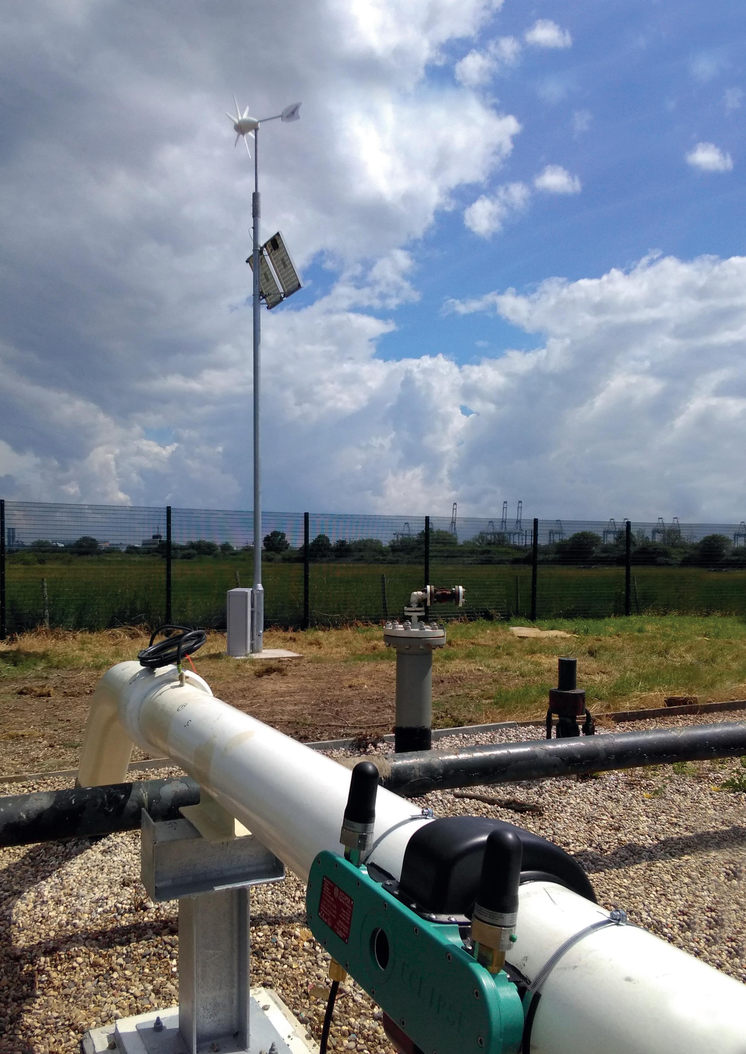
Harry Smith, Atmos International, UK, discusses how to improve storage operations with pipeline technology.
Whether they are for short or long-term storage, tanks and tankers are integral to the downstream phase of a gas or liquid’s transportation.
While tank farms and terminals temporarily store commodities ranging from water, oil, and petrochemical products before they are transported to customers or another tank farm, tankers are mobile and combine the storage and bulk transportation of commodities.¹ Both tanks and tankers are crucial in the fulfilment of most of the world’s energy needs, with pipelines also playing a pivotal role.
From the complex networks connecting tanks at tank farms to a tanker’s product transfer, pipelines facilitate downstream storage operations.² While it is the safest mode of transportation, there are many pipeline challenges that can threaten tank and tanker operations.
Corrosion
Corrosion is inevitable on any pipeline and is caused by external factors like the air, soil, and water. Corrosion is the leading cause of pipeline incidents.³ In the context of tank farm pipelines, corrosion could be accelerated by the repeated transportation of hydrocarbons and chemicals in and out of storage tanks. For tanker loading and unloading pipelines, corrosion could manifest in the form of seawater properties depending on its salinity, pH and oxygen levels.4
Short pipelines are commonly used in tank and tanker storage operations. While not impossible, it is typically harder to install instrumentation on short pipelines due to the lack of opportunities and space for metering.
Anchor strikes
Even with its anchor dropped, a ship tanker can still move back and forth and its anchor can snag a connecting pipeline, causing product to leak into the surrounding area.5
Passing ships can block data communications
Communication can be a challenge on a monobuoy if line-of-sight communication is used. Once connected to the buoy, a ship can break this sight as it rotates in the water. This is another factor contributing to the difficulty of installing instrumentation and communication on the offshore part of the pipeline.
Offshore pipelines have monobuoy used to connect the ship to the pipelines for the loading and unloading of fuel. It can be a challenge to install instrumentation on this type of buoy due to spacing issues, power requirements, and communication needs. This can make installing a standard leak detection system (LDS) difficult as it is not always possible to have instrumentation at each end of the pipeline.
Atmos has developed a method of providing leak detection utilising instrumentation at only one end of the pipeline.
Tanks and tankers can contain commodities ranging from chemicals to oil and gas, all of which can have catastrophic environmental impacts in the event of a pipeline leak and long-term effects on climate change.

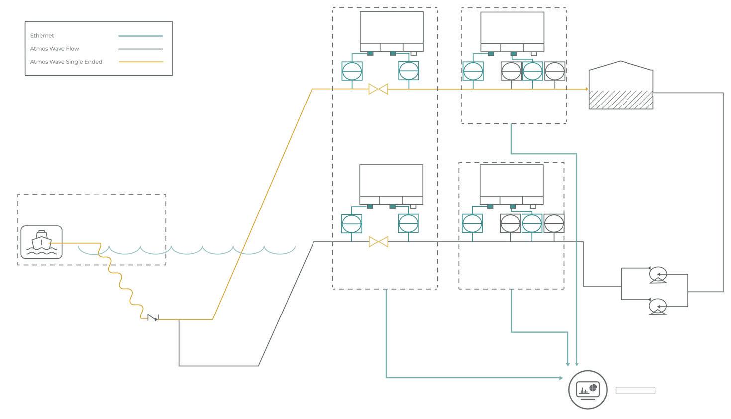
For a pipeline loading and unloading a tanker, a leak in any capacity can impact the marine environment and there have been incidents across the world where biodiversity in protected aquatic areas has been affected by tanker leaks and spills.6,7 For tank farms where fuel storage can involve gases, pipeline leaks can be difficult to identify unless the gas has a colour, odour or if there is an effective leak detection solution in place.8 Gas leaks that remain unnoticed can cause greenhouse gas emissions as well as being a fire hazard, posing a risk to health and impacting surrounding air quality.9
In addition to environmental damage and the offending tank or tanker company’s reputation, financial damage can follow a leak event to account for harm caused to the surrounding area and clean up costs.
These factors are not an exhaustive list of challenges associated with tank and tanker pipelines. Pipeline systems can be complex, every pipeline behaves differently and no single technology is the best, but the following two

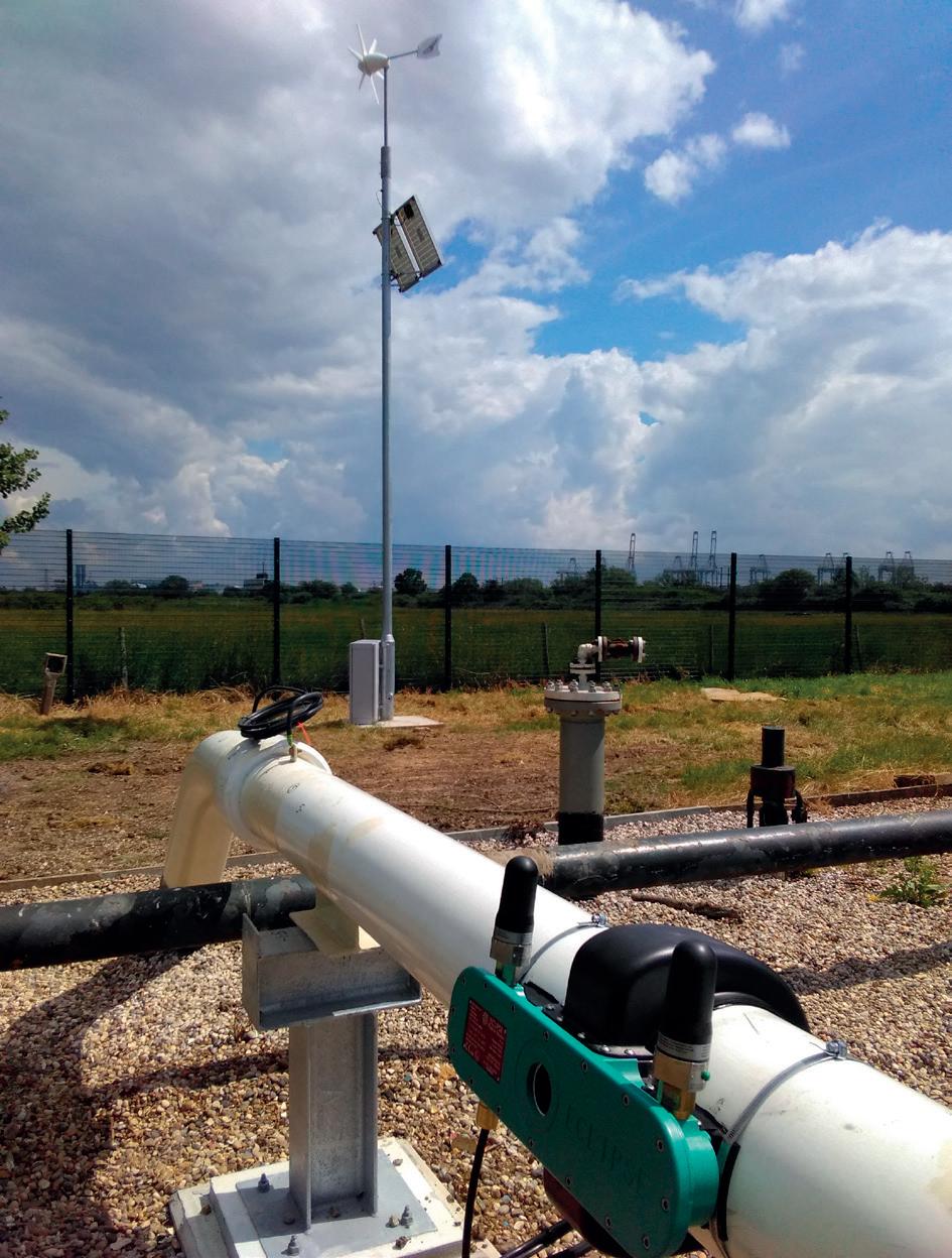
case studies outline solutions to some particular tank and tanker storage operations.
With demand for fresh water increasing every year, desalination increasingly grows in popularity as a means of producing more water. This requires the transportation of water from desalination plants to the areas where water is needed, and it depends on the use of large water tanks and pipeline networks.
While desalination operations follow a routine cycle, an optimiser presents opportunities for planning maintenance, dealing with equipment failure or supply interruptions and in planning extensions to the pipeline network. This was the case with a long-range water transmission network where inventory control is done in the tank farms.
Solving pipeline capacity, flow rates, and tank levels can achieve an optimal solution for pumping schedules, which can then be validated by running a transient simulator using the resulting pressure and flow setpoints, and pump line-ups. It can be used to answer design questions related to:
n If a pipeline can meet its delivery schedule without depleting the tanks.
n Whether a delivery schedule can be met if the pipe’s minimum allowable operating pressure needs to be reduced.
n If the pipeline operation can be run on tank pressure for the day in the event of failure in multiple pumps.
For complex tank operations, using simulation software is vital to overcoming obstacles such as potential supply
interruptions, pipeline sections being out of service for maintenance and other operational problems.10
For a subsea to onshore diesel pipeline in Latin America, the customer required a leak detection solution that both improved operations and complied with their regional regulations.
A 1 km pipeline unloads fuel from tankers offshore to tanks onshore and involves three distinct operations: unloading of fuel from the ships, flushing, and static.
Using wave flow technology, the customer’s flushing and static operations were improved, but the customer had an additional goal of performing leak detection each time a ship is being unloaded by including one-sided instrumentation. Atmos Wave was selected because it can provide a single ended leak detection solution while being easy to retrofit to the pipeline.
When it comes to tanks and tanker leak detection, single ended leak detection is the solution because it is an easier installation and can utilise existing instrumentation while providing increased data acquisition and resolution.
Short pipelines are typically used in a tank or tanker operation (much like in case study 2) which can sometimes make it harder to install the appropriate instrumentation. Non-intrusive hardware is available in some ATEX packages and can be designed for rapid deployment. The company has already installed Atmos Eclipse units on tank farms across the globe, some using vertical fixings and within tight spaces.
For tank and tanker networks that have an opportunity to improve operations, Atmos’ Simulation Suite can help operators respond quickly to ongoing changes in supply and demand, forecast future pipeline operations and more, as seen in case study 1.
1. MODISETTE, J., ‘The Atmos Book of Pipeline Simulations,’ https:// www.atmosi.com/en/resources/books/the-atmos-book-of-pipelinesimulation-chapter-one/
2. ‘Bulk Fluid Storage,’ https://www.sciencedirect.com/topics/ engineering/tank-farm
3. SMITH, H., ‘Considering the challenges of optimising aging pipelines,’ https://www.atmosi.com/en/news-events/in-the-media/pipelinetechnology-journal-ptj-considering-the-challenges-of-optimizingaging-pipelines/
4. CAI, M. ZHAO, Z., SUN, W., YIN, X., ZHANG, Y., and HE, S., ‘Impact of pipeline materials on water quality stability of desalinated seawater in the pipeline network,’ Desalination, Vol. 556, (June 2023).
5. SORAGHAN, M., ‘Pipeline owner kept “in the dark” on possible anchor strike,’ https://www.eenews.net/articles/pipeline-owner-kept-in-thedark-on-possible-anchor-strike/
6. RATCLIFFE, R., ‘Philippines oil tanker spill prompts fears for protected maritime areas,’ The Guardian, (March 2023), https://www.theguardian. com/world/2023/mar/03/philippines-oil-tanker-spill-prompts-fearsfor-protected-marine-areas
7. COLLYNS, D., ‘Oil spill at sea: who will pay for Peru’s worst environmental disaster?,’ The Guardian, (March 2022), https://www. theguardian.com/environment/2022/mar/07/oil-spill-at-sea-who-willpay-peru-worst-environmental-disaster
8. GODDARD, ‘Update on bp tank farm leak,’ Region News Source, (January 2024), https://regionnewssource.org/update-on-bp-tank-farmleak/
9. SEGAL, E., ‘New Research Shines Light On Natural Gas Leak Crisis,’ Forbes, (February 2022), https://www.forbes.com/sites/ edwardsegal/2022/02/17/new-research-shines-light-on-natural-gasleak-crisis/
10. MODISETTE, J., ‘Dynamic pump and tank optimiser for water networks paper,’ https://www.atmosi.com/en/resources/technical-papers/ dynamic-pump-and-tank-optimizer-for-water-networks-paper/
Mark Naples, Umicore Coating Services, considers the benefits of infrared gas detection in the oil and gas storage sector.
Whether it is an individual worker or the whole facility, safety is paramount in the tanks and terminals sector.
From combustion to poor air quality, anyone involved in the extraction, production, storage, or transportation of oil and gas risks exposure to leaks. Emissions like methane, benzene,
and hydrogen sulfide can be difficult to detect without specialist equipment, and may represent serious threats to personnel and equipment alike.
Mitigating these threats depends heavily on regular, targeted maintenance programmes. However, optimising maintenance can be easier said than done. Organising repairs for maximum impact


requires oil and gas companies to understand where they are most needed. Without adequate data, this can prove difficult if not impossible.
Early detection is instrumental to ensuring a safe working environment. Knowing where potential hazards occur enables businesses to act on them quickly and efficiently, reducing production losses and helping maintain regulatory compliance. Successful preventative maintenance, empowered by robust gas detection technology, will reduce downtime and significantly improve workplace safety by eliminating key risks to employees and infrastructure alike.
The danger posed by gas leaks cannot be understated. Exposure to toxic gases can contribute to both

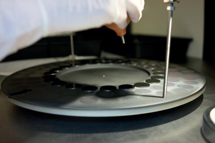
long-term and short-term health conditions, ranging from mild irritation from shorter periods of exposure through to lasting respiratory illnesses, unconsciousness, or even lethal occurrences. Oxygen deficiency caused by particularly high concentrations can lead to asphyxiation, and the flammable nature of many gases can create explosive atmospheres if allowed to accumulate in sufficient quantities.
Gas leaks also represent a threat to environmental and regulatory compliance. Substances like methane have significant heat trapping potential and are major contributors to global warming, accounting for approximately 30% of the rise in global temperatures since the Industrial Revolution. Failing to control these emissions may see businesses subject to penalties including fines or legal sanctions, as well as reputational damage. Investors may also use environmental, social and governance (ESG) compliance to evaluate potential investments, so companies that are seen as being lax on safety and environmental issues risk becoming unappealing investment propositions.
Although some common emissions from oil and gas operations can be detected by smell alone, this is often unreliable, especially in higher concentrations. Hydrogen sulfide in particular has a distinct scent, but high exposure to it can cause olfactory blindness that makes detection almost impossible. Other gases like carbon monoxide are odourless and cannot be detected without monitoring equipment. As a result, in order to take action against emissions companies must start improving their data.
Preventative maintenance strategies should be the end goal of any organisation looking to address the threat posed by gas leaks. As opposed to reactive maintenance, this process relies on gathering information to accurately forecast emerging problems, enabling tank and terminal operators to organise an efficient and effective course of action.
Predictive maintenance requires businesses to understand where problems are likely to occur. Technologies that prevent these kinds of incidents can help companies reduce the inefficiency of maintenance scheduling and associated downtime, thereby increasing productivity. Businesses that invest in such programmes can reap benefits including significant reductions in downtime and maintenance expenses, as well as optimising their maintenance programmes to minimise workplace disruption. Addressing potential problems before they escalate has the added benefit of extending equipment lifespan, further reducing operational costs through reductions in replacement frequency.
Data is key to making detection work. Leveraging data analytics powered by Internet of Things (IoT) sensors and artificial intelligence (AI) machine learning (ML) algorithms enables businesses to optimise the accuracy of their maintenance programmes. With this information in hand, it becomes much easier to
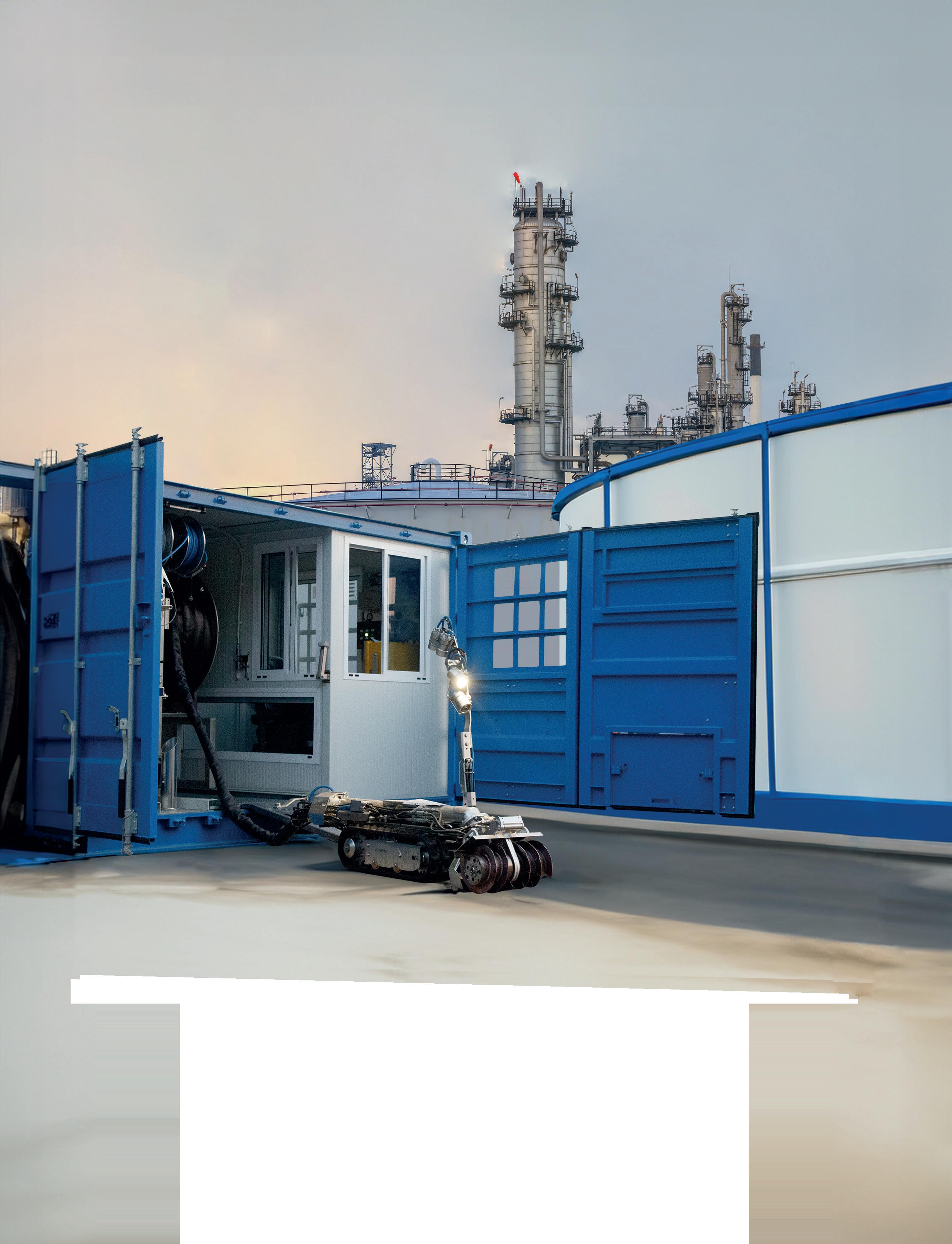

schedule thorough risk assessments to identify potential hazards and provide staff with the appropriate training.
Vibration monitoring technology presents one avenue for improving the data that companies have, enabling them to measure the vibrations of important equipment and detect any abnormalities. Ultrasonic testing can also help to identify flaws in pipelines or tanks, such as leaks, before they spiral out of control. However, one of the more effective tools that energy suppliers have access to is laser absorption spectroscopy.
Laser absorption spectroscopy enables the energy sector to tap into the world beyond human senses and easily identify trace gases with unmatched sensitivity. While these sensors can be designed for any part of the electromagnetic spectrum, many gas analysis devices focus on the infrared region. This is because many substances including methane, carbon dioxide, and other hydrocarbons absorb infrared light very strongly, and are therefore easier to detect under this wavelength. Using infrared light has the additional benefit of there being multiple spectral lines that characterise the absorption profile of these gases in the infrared. As a result there are several features in the spectra that can be used to identify chemical species with great accuracy, providing a wealth of otherwise inaccessible information.
The technology is based on measuring how much infrared light is absorbed by a gas sample as it passes through a medium. Emitters within a device generate lasers that pass through a sampling chamber containing an advanced filter. This filter blocks all but the selected wavelengths – those absorbed by the particles of gas being monitored – from passing through to the detector. Changing the filter enables the detection of different gases and distinct particles.
This technology is highly selective, meaning other gases present cannot influence the measurement, and offers fast response times without the need for other consumables such as calibration gas, reducing operating costs. Crucially, the nature of this technology makes it suitable for use in challenging environments where corrosive elements or temperature fluctuations could damage the integrity of other equipment.
With the power of this sensing technology, today’s oil and gas companies have access to a gas detection system for every conceivable need. Fixed infrared detection systems can be installed in confined spaces or in areas that are at permanent risk of a leak to continuously monitor for dangerous concentration levels. Portable, handheld detectors enable workers to monitor for gas leaks wherever they are, enhancing personal safety and detection flexibility across a wide area.
Deploying this advanced equipment at both local and national levels enables detection of leaks as they occur, improving the understanding that companies
have of where leaks are occurring, as well as the collective understanding of national emissions profiles. Compared with satellite infrared imaging, which can be disrupted by water, local networks of small form factor devices are better able to operate in offshore areas or in humid conditions. Deployed across pipelines, storage facilities, and transport hubs, infrared spectroscopy is developing humanity’s understanding of emissions, helping oil and gas companies to better comply with tightening regulations and identify inefficiencies throughout their operations. Such networks are only now becoming viable thanks to advances in optical coating technology lowering the cost of sensing devices.
Filter and coating design is central to the success of laser absorption spectroscopy. Coatings applied to a filter play a pivotal role in determining whether filters are suitable for a given application, and advancements in this field have contributed to the scalability of the process. A custom-designed precision optical filter can be the difference that sets one sensor apart from another as businesses seek the technology to help protect their employees and assets.
With sensor manufacturers demanding increasingly high performance filters at more affordable prices, specialist filter coating manufacturers aim to shape the future of gas detection devices. Working with partners like Umicore, which collaborate with customers to develop custom infrared designs, opens new possibilities for performance on gas detection. Such partners can offer a wide range of bandpass optical filters ideally suited to all gas detection and analysis applications, with a centre wavelength anywhere on the near-infrared (NIR) to far-infrared (FIR) spectrum with steep-edge and deep blocking capability.
Thanks to these technological advances, high performance gas detection systems are now more affordable and accessible than ever. These powerful sensors are already granting businesses oversight of their infrastructure, enabling them to detect potential problems as soon as possible and begin preventative maintenance procedures. As a result, tank and terminal companies can achieve higher productivity, lower emissions, and a safer, healthier working environment.
By implementing infrared gas detection systems, oil and gas companies can move towards a future characterised by greater efficiency, environmental responsibility, and worker safety. Early detection of leaks empowers businesses to take preventative action, minimising production losses and environmental impact. Partnering with filter coating manufacturers further enhances the effectiveness of gas detection technology, ensuring superior performance and unmatched sensitivity. As the technology continues to develop and become more affordable, widespread adoption of infrared gas detection has the potential to revolutionise the safety and environmental landscape of the oil and gas industry.

Chris Platt, Re-Gen Robotics, discusses how the adoption of a robotic tank cleaning philosophy can significantly reduce safety risks.
In the modern world of high hazard, heavily regulated industries such as oil refining and tank storage, huge effort is devoted each year to reducing risks and protecting people. CEOs continuously remind all employees that ‘safety is their first priority’. Managers up and down organisations are charged with delivering improved safety, health, and environmental (SHE) performance.
Environmental, social, and governance (ESG) programmes are developed to communicate to all stakeholders that organisations are reputable, modern, and focused on ‘doing the right things and doing things right.’
When exhortations of these kinds to work safely are applied to the cleaning of aboveground storage tanks, site teams are faced with a number of issues. Using traditional methods based on confined space entry (CSE) tank cleaning has long been a challenging and hazardous task. During manned entry, workers face numerous risks, some with extreme consequences including exposure to toxic chemicals as well as flammable and/or oxygen-deficient atmospheres.


Conventional CSE, if it is to be carried out safely, relies heavily on the use of personal protective equipment (PPE). Operating companies are all too aware of the difficulties of ensuring full compliance with PPE requirements. PPE may not be worn as the manufacturer intended, it may be of the wrong specification, or it may have become defective during use. Breathing apparatus is hot and uncomfortable and rapidly leads to fatigue. Safe usage requires constant and vigilant monitoring by trained personnel. Conventional CSE also requires fully compliant implementation of operating procedures in an environment with significant quantities of toxic and often flammable sludge. Ensuring that all the working parts of a complex procedure come together in a timely manner is always a challenging task. Such procedures often consist of 50 – 60 pages of closely-written ‘corporate memory’ regarding ways to avoid incidents that have happened previously on that site, in that company or within the industry. These documents may or may not be well understood by those who are required to act in accordance with them. They rely on the effective coordination of the inputs of multiple different personnel from both the operating and contracting companies, together with thorough training and effective communication. Hence, incident free tank cleaning relies on outstanding compliance with operational procedures and PPE requirements.
The difficulty with this is that operating companies regularly learn that their permit-to-work procedures upon which CSE relies, can and do fail in a myriad of different ways, on a regular basis. Weekly SHE reporting meetings frequently register PPE compliance failings. Incident investigations regularly feature permit-to-work and other procedural failures. During a confined space entry, sadly, such failures of key risk reduction measures rarely have minor consequences.
Where consequences of an incident are high, it is right to examine the quality of risk mitigation measures that organisations rely on. Looking at one of the classic diagrams from SHE Management theory (Figure 1) it shows that PPE sits at the bottom of the hierarchy of risks, in terms of effectiveness of risk mitigation. Organisationally, it is relatively easy to provide operatives with PPE, but overall such measures are the least reliable ways to prevent incidents. The number of cut fingers in the industry remains high, despite the wide availability of suitable gloves, as one example. In the CSE case discussed earlier, the recognition of the fallibility of PPE has led to a conclusion that elaborate administrative controls, i.e. operating procedures, are required to supplement PPE as risk mitigation measures. But whilst better than PPE, administrative controls are only marginally more effective.
For a management team charged with improving SHE performance in the cleaning of storage tanks, what is really needed is an approach to the task that is capable of rising above the limitations of PPE and administrative controls – an approach unencumbered by low capability risk mitigation measures. What is needed is a way to
embrace some of the higher level risk control options shown in Figure 1.
One way to do this is to embrace the fourth level of the triangle i.e. to isolate the human from the risk. This may be achieved by sending a remotely operated vehicle into tanks of sludge, in place of a human being. The hazards inside the tank remain, but humans are no longer subject to them. Operatives who previously laboured for what could be up to 6 months in terms of total job length, working inside sludge filled tanks, physically manhandling waste to the manway, are now able to be more effective. They can remove sludge quicker, sitting at the controls of a robot while remaining inside a control room outside the tank.
A typical 50 m (165 ft) crude oil tank might require up to 5000 man hours of exposure to CSE hazards when carried out in the traditional fashion. This can be avoided with the use of robotic technology.
With the advent of robotic tank cleaning, the oil industry has the potential to achieve a significant improvement in risk mitigation and this will feed through to consequent safety performance. Adopting a robotic tank cleaning philosophy, represents a step change in risk reduction for an operating organisation.
How capable are robots today? In the context of cleaning the inside of storage tanks, robots are extremely capable. They can be engineered to comply with the most rigorous ATEX Zone 0 (Class1 Div1) electrical safety standards. They can be used in tanks containing a wide range of raw materials and products, both black oils and volatile white oils. They are designed to effectively remove even the most viscous materials (Figure 2) such as heavy fuel oil (HFO), which resists pumping at typical atmospheric temperatures. There are robotic systems which are designed to include ADR/Vac. tanker, control room, robot, and Hiab crane. Such systems can allow for rapid set-up on site and requires no modification to either the tank wall or roof to provide entry points, utilising standard 24 in., 600 mm manways. Effective robots can be fully submerged in oil, with cameras and lights on arms which rise above the liquid level where necessary.
Controlled from a portable control room located outside the tank, often in the tank bund, the robots, or more accurately remotely operated vehicles (ROVs), are propelled via catapillar tracks, powered via hydraulic systems. Different track designs allow lined tank floors to be accommodated, without damaging the tank floor or walls. The robots utilise low voltage cameras and lights to allow their remotely located operators to precisely position them within the tank. They can manoeuvre around tank furniture such as roof drains, roof support legs and steam coils. They suck liquids and sludges by one of a range of suction heads connected via a 4 in. (100 mm) or 6 in. (150 mm) hose to a suction tanker outside the tank. There is no limit to the size of tank that can be cleaned. The most stubborn sludges are usually
removed with the addition of high pressure water or steam or in some cases crude oil or gas oil cutting fluids. The water/oil mixture is then separated from the original tank contents once they have been removed from the tank.
In addition to the benefits already outlined, robotic operation also delivers improvements in the following areas:
Robots are equipped with advanced sensors and imaging technologies that allow them to precisely navigate within tanks, successfully circumventing roof support legs. They utilise a range of different suction heads, designed to reach under, over and around internal heating coils, roof drains, and other internal tank furniture. This facilitates access to challenging locations and ensures thorough cleaning. This level of precision not only results in a higher quality of cleaning but also reduces the likelihood of contaminants remaining in the tank, posing risks to future tank entrants who may be present to conduct inspections.
Tank cleaning methods involving CSE often involve physical exertion and repetitive activities, leading to potential musculoskeletal strain and injuries. Robotic systems eliminate this hazard, as it is the robot that takes the strain. Robots are not susceptible to the weaknesses of pre-existing medical conditions, ill-health, twisted joints, pulled muscles or fatigue. Health monitoring regimes can be reduced as the exposure of workers to toxic materials is decreased and long-term liabilities of employers are therefore also reduced.
Robotic tank cleaning systems are also designed to minimise environmental impact. They typically utilise less water and/or cutter stock than manual processes, such as water jetting or the employment of water cannons, thereby reducing the burden on waste treatment systems. This both facilitates compliance with environmental regulations and leads to reduced waste declarations, improving sustainability. This not only contributes to a safer work environment but further supports the achievement of ESG targets.
Robotic tank cleaning has developed as an emerging technology in industrial cleaning processes, revolutionising safety standards in hazardous environments. By reducing human exposure to risks, limiting the need for CSE and enhancing cleaning precision and efficiency, this technology not only protects workers but also improves the quality and sustainability of industrial operations. As the industry continues to adopt and support the development of such approaches, operating companies can expect even greater strides in safety and efficiency in the years to come.


Roger Simonsson, Aquajet, Sweden, explains the benefits of robotic hydrodemolition equipment for oil and gas tank cleaning.
Industrial facilities rely on high-pressure water-jetting machines for cleaning and removal applications in oil and gas tank storage to keep equipment operating at full potential. Enhancing efficiency for surface cleaning and preparation is vital for maintaining productivity and profitability. To help keep facilities running smoothly and optimise scheduled downtime, industrial cleaning specialists employ a variety of handheld and automated water-blasting equipment designed for these oil and gas tank applications.
However, what these tools provide in terms of efficiency – and long-term benefit to the contractor – depends on many factors. Selecting the right equipment goes beyond how fast crews can get the job done. It must include considerations for safety as well as productivity. Additionally, equipment that allows an operation to expand service offerings without further investment is the best choice for continued growth and overall stability.
This has led a number of industrial cleaning contractors to invest in robotic hydrodemolition equipment from original equipment manufacturers (OEMs). These cutting-edge machines offer a number of safety and productivity benefits compared to handheld equipment or homemade systems and increase contractor flexibility over highly specialised, single-application options.
Industrial cleaning applications come with a number of inherent dangers. Limiting crew exposure to these hazardous conditions is a primary concern for contractors and has led to the development of numerous automated options. The extent to which these solutions keep workers out of harm’s way varies, as does the amount of

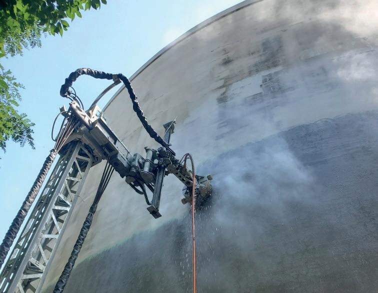
personal protective equipment (PPE) required. Additionally, due to the specialised nature of oil and gas tank cleaning, the use of automated equipment might be limited in some situations, leaving contractors to rely on more manual solutions – unless they have access to powerful robotic equipment. For example, a contractor might be able to perform a basic tank cleaning application with an automated system, such as a rotating jet lowered from the top of the tank. But what if the project requires a more thorough cleaning or the removal of materials such as paint or coatings? To achieve the necessary power for this type of cleaning, contractors often employ crews in full PPE wielding hand lances.
This method significantly increases the safety risks for crews. Because they must constantly resist back thrust, hand lances cause workers to fatigue quickly. A worker using a 40 000 psi hand lance must constantly fight up to 52 lb of thrust (at a flow of 5 gpm) for normal operation. The Waterjet Technology Association recommends, in ideal conditions, a single worker should not be required to withstand back thrust of more than one third of their body weight for an extended period of time. In poor conditions, such as low light, uneven or slippery footing and confined spaces, even less back thrust is recommended.
Hand lances also come with increased risk of hand, wrist, shoulder and back injuries, since they require workers’ bodies to absorb the shock of the cleaning or removal process. Even more dangerous, though, is the risk of water jet-related accidents. Improperly controlled high-pressure water jets can cause serious foot and leg injuries and have even contributed to fatalities.
On the other hand, using advanced hydrodemolition robots for this same tank cleaning task allows workers to remain at a safe distance and operate the unit via remote – even from outside the tank in some cases. While this increased area of operation does not eliminate the need for PPE, it allows workers to safely complete the cleaning without the requiremnet of full body suits or breathing apparatus, saving time, resources and discomfort.
Compact units from industry-leading OEMs offer further increases to jobsite safety by eliminating the need for workers to enter confined spaces such as tanks and pipes. Some advanced models can easily be broken down into smaller components – a third of their original size – that can enter these tight and inhospitable environments.
Advanced systems from industry-leading OEMs can also reduce or even eliminate the need for scaffolding – another common safety risk for industrial cleaning specialists. Remote operation allows workers to stay safely on the ground and away from ledges or fall hazards. Eliminating the need to erect scaffolding or fall protections also increases overall productivity.
One type of innovative system features a lightweight, compact control unit and robotic power head with high-pressure lance that attaches to and robotically moves along standard scaffolding pipes. This setup is ideal for quickly covering large areas without requiring crews to work at height. Larger hydrodemolition robots are another option. These advanced units feature an innovative steel
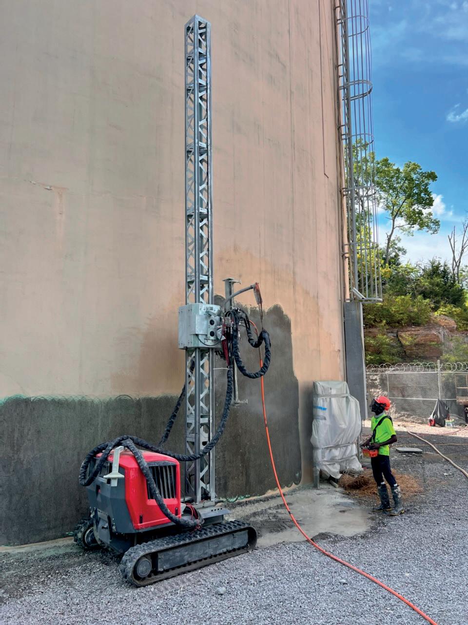
Figure 3. Operating at pressures up to 40 000 psi, hydrodemolition robots provide improved productivity compared to hand lances and other automated options for removing concrete, paint, and other coatings.
mast section with a reach of up to 23 ft (7 m) that can eliminate the need for scaffolding altogether. Additional mast sections can be employed to extend reach for larger projects, as well.
Increased worker safety is only part of the equation when it comes to overall equipment effectiveness. For oil and gas tanks, routine maintenance and cleaning, though necessary, is a costly undertaking. As such maximising productivity must be a top priority for successful industrial cleaning contractors.
Among automated options, robotic hydrodemolition equipment has proven to provide optimal efficiency, where applicable. Specialised equipment for applications such as tank cleaning is widely used across the industry, removing workers from some of the most dangerous and challenging jobs. But these still require support crews that vary in size. A hydrodemolition robot, on the other hand, can perform many of the same applications with a single operator. This allows contractors to better utilise crews and maximise productivity across the jobsite.
Operating at pressures up to 40 000 psi, hydrodemolition robots also offer improved productivity compared to hand lances and other automated options. For removing paint or other coatings, powerful hydrodemolition equipment again provides maximum productivity compared to
hand lances. This is due to the robot’s ability to handle the higher water flow rates and reaction forces necessary for successful material removal.
At 40 000 psi, hand lances can only safely offer 5 - 6 gpm for reaction forces up to 62 lb thrust, whereas compact hydrodemolition robots can easily handle 30 gpm for up to 312 lb thrust of reaction force. So, while a hand lance might be used to remove concrete, the process would be far more time and labour intensive with removal rates of just 0.5 - 1.0 ft3/hr. Compare that to a compact hydrodemolition robot, which can remove concrete at rates of 10 ft3 – almost 10 times faster.
The increased productivity offered by robotic hydrodemolition equipment means industrial cleaning specialists, and facilities, can optimise operations during scheduled downtime. Contractors are able to complete cleaning applications faster and with less labour, leaving them free to move on to the next job while the facilities can restart production more quickly.
But what exactly is the next job? For many contractors, adding advanced hydrodemolition robots to their fleet not only increases productivity and safety for industrial cleaning applications, but opens the door to increased service offerings and long-term company growth.
Thanks to a variety of attachments from innovative OEMs, contractors can tailor hydrodemolition equipment packages to fit the current – and future – needs of their operation. For example, a number of OEM attachments exist that allow for more efficient material removal in tanks and pipes. Other attachments enable removal of paint, rust and coatings along an entire section of horizontal, vertical or inclined pipes.
In addition to attachments, hydrodemolition OEMs also provide support equipment that can increase efficiency for industrial cleaning applications as well as open up new revenue opportunities. A silent running high-pressure pump/engine combination exists, which provides the necessary pressure for industrial cleaning applications, but is quiet and compact enough for any urban jobsite. This system is available at up to 700 hp and features integrated auto start/stop technology that improves fuel consumption – saving as much as 25 l/d (6.6 gal./d) of fuel – while operating at up to 3000 bar (43 511 psi) and under 65 dB.
Capitalising on industrial cleaning safety, productivity and growth potential starts with investing in the right tools for today – and tomorrow. There are a number of specialised industrial cleaning mechanisms available that provide an automated solution to help limit worker exposure in the most hazardous conditions. But for forward-thinking contractors, these methods fall short when compared to the power, versatility and safety offered by compact hydrodemolition equipment. Working with reputable OEMs to customise hydrodemolition equipment packages that meet current and future business goals can help ensure long-term success.
Tim Gale, 1898 & Co., emphasises the importance of implementing an effective cybersecurity programme.

Industrial cybersecurity is the practice of protecting industrial control systems (ICS), which are integral to the operation of all critical infrastructure sectors including process industries, pipelines and terminals. To secure these systems, it is imperative to establish a comprehensive industrial security programme to maintain awareness, increase resilience, and enable recovery from cyberevents.
Information technology (IT) and operational technology (OT) serve very different roles within an enterprise. IT is comprised of systems used for data management, including computers, networks and software applications supporting business operations and communication.
In contrast, OT refers to a wide variety of purpose-built hardware and software that monitors, provides communication and controls processes that manufacture products, chemicals, and pharmaceuticals, as well as treat water and pencil in many other
industrial operations. Falling in the OT category, an ICS is an umbrella term that includes systems like distributed control systems (DCS), supervisory control and data acquisition (SCADA), and safety instrumented systems (SIS). As these systems are in direct control of equipment and processes, they are essential to promote the continuous safety of personnel and the environment.
Given the essential role of an ICS, the security and resilience of OT operations in critical infrastructure sectors is paramount to national security, economic stability, and public safety.
The OT environment faces a wide variety of threats that must be considered when developing a security programme, including:
Malicious software can disrupt or take control of ICS operations. This may impact both IT and OT operations as it targets computers used in both and threatens to encrypt and hold these
systems hostage until a ransom is paid. There is no guarantee these systems will be restored, leaving the victim having to attempt to recover from backups or rebuild the systems.
An asset owner does not necessarily even need to be the intended target of this malicious software, as the malicious code once in circulation will find victims indiscriminately.
APTs are skilled, malicious actors, conducting long-term targeted attacks often sponsored by nation-states, aiming to compromise an ICS for sabotage. These sophisticated campaigns infiltrate networks, often for lengthy periods of time before discovery, intending to disrupt operation to further the agenda of their sponsors.
Deploying and maintaining an ICS often relies on a complex supply chain, making it vulnerable to tampering. This may include insertion of malicious hardware or software prior to equipment delivery to the site. A dependency on third-party vendors creates security weaknesses in products or services that can be exploited.
Because of the essential role of an ICS in critical infrastructure, it is imperative to develop a robust OT security programme. The foundation of this programme must include the following elements:
Effective incident response and recovery planning are essential for business continuity. Organisations should develop comprehensive plans to address identification and response to cyberincidents. Following the initial response, plans must be developed for the effective recovery of operations, which includes the testing of backups to enable recovery from malicious software attack.
Tests and drills are crucial for effective OT incident response, as they prepare processes and personnel to handle real-world cyberthreats. Regular testing of incident response plans helps identify weaknesses and gaps, allowing these to be addressed before an event occurs. Drills are vital for OT security readiness, as they train and prepare personnel to respond effectively to cyberthreats.
Risk management is essential, as it helps organisations understand their vulnerabilities, prioritise threats and implement appropriate security measures to protect against disruptions. By implementing a robust risk management programme, organisations can enhance their resilience and reduce the likelihood of successful attacks.
Risk must be identified during all phases of operation, including engineering and design, construction, and during normal operations. Including design reviews in the risk management programme allows knowledgeable and experienced security professionals to collaborate with control system designers to confirm that appropriate control system architectures are included prior to purchase of equipment and deployment to the site.
Asset identification is crucial for ICS security, as it enables an understanding of the components in the industrial infrastructure to facilitate effective risk and vulnerability management.
Strong defence in ICS architecture is crucial for safeguarding critical infrastructure and industrial operations. By implementing layers of protection such as firewalls, network segmentation and access controls, organisations can mitigate risks and limit unauthorised access or manipulation of critical systems.
Sound ICS architecture and hardening should be included as part of basic minimum-security standards. These must include the risk-based decisions previously mentioned, as well as basic hardening of all ICS computers, switches, and other OT components.
ICS computers must be protected from malware with effective antivirus and application control solutions. Application control helps to limit software, checking that only authorised and trusted applications are permitted to operate.
Patching must be managed to address known vulnerabilities in ICS computers and other components such as switches and firewalls. It is important to include the ability to test and verify patches in a safe environment and also to have a plan to roll back off a patch if it adversely affects operation.
Physical security is also important when it comes to limiting access to ICS components and must include perimeter and building security as well as panel locks and separation of IT and OT network components.
Monitoring and detection are critical in securing an ICS and combined with a robust defence, provide a strong foundation for an ICS security programme. Continuous monitoring allows organisations to gain real-time visibility into their OT networks and provides an opportunity to detect any suspicious activities or deviations from normal ICS behaviour. Network traffic analysis, anomaly detection and endpoint monitoring allow organisations to identify unauthorised access attempts, malware infections, and abnormal behaviours.
The basic security elements must be developed into a set of engineering standards that limits the opportunity to deploy unsecured systems to the field. These standards should include requirements for network design and segmentation, wireless networks (if applicable), access controls, secure remote access, and secure management of OT network infrastructure.
It is important to include exception cases in the engineering standards for conditions like commissioning of systems where controls may not be fully implemented or bypassed to facilitate multiple users or third-party remote access.
The engineering process should include a provision for addressing security risk though thoughtful design and elimination of unnecessary features or components rather than through addition of technology as a mitigating control.
Engineering standards must also address technology obsolescence such that a plan exists for the upgrade of unsupported computer operating systems and ICS components in a programmatic way rather than ad hoc, without proper planning.
Governance is the bedrock of an effective OT security programme, providing the framework and oversight necessary to manage risks, enforce policies and maintain compliance with regulatory standards. Establishing roles, responsibilities, and accountability for security-related activities within the ICS environment is crucial to a programme’s success. A role-based training programme is important not only to raise general security awareness but also to focus on targeted training for activities like engineering design and incident response.
When it comes to development of a security programme for an ICS, there are numerous pitfalls that must be avoided. In some cases, policy and procedure are developed ad hoc and are not consistent with the actual systems deployed or the use cases required for operation. In some cases, the programme is stalled and fails when a large project comes along where insufficient policies and standards are finalised. And in other cases, the programme is developed but insufficient training exists to effectively execute procedures or harden endpoints prior to deployment in the operating environment.
Whether developing a security programme independently or working with a partner, it is important to take these good practices into account:
n Focus on the ability to recover: develop and test recovery plans with site personnel who are intimately familiar with the systems involved. Conduct regular table top exercises,
use the lessons learned, and treat them like training opportunities.
n Understand the risks: failure to properly understand and manage risks may lead to improper prioritisation of assets and funding. Carry out a comprehensive risk assessment and address the high priority items first. Use the risks to inform development of policies and procedures.
n Raise awareness: all key interested parties in an industrial operation have a part to play in an OT security programme. Train early and often to prepare personnel for their role.
n Be aware of resource constraints: personnel with other responsibilities, lack of budget and lack of training or knowledge may impede the development and implementation of an OT security programme.
n Start: it is never too early to start the development of a programme. If you are starting from zero, begin by documenting what ICS equipment you have, how each is managed, who the key interested parties are, and if you could recover from a cyber event.
The security and resilience of industrial control systems in critical infrastructure sectors are essential to maintaining the continuous and safe operation of essential services. As the threat landscape evolves, organisations must adopt comprehensive strategies that address both cybersecurity and physical security.
By implementing an OT security programme built on good practices, companies can protect their most critical ICS from threats and maintain long-term operational stability.

Proven, advanced formulations ideal for your processes, industry, and applications. More and better choices in heat transfer fluids based on our over 35 years experience.
www.paratherm.com
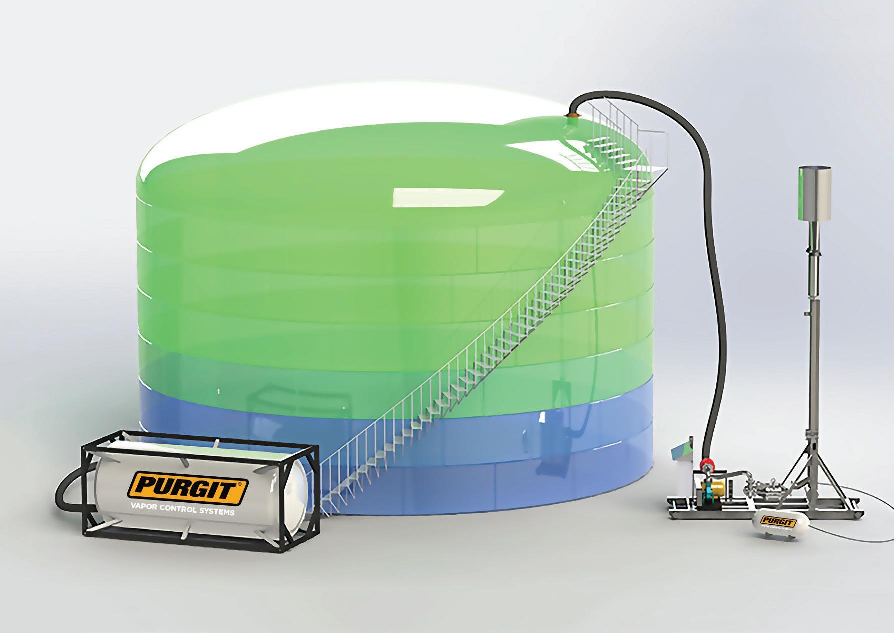
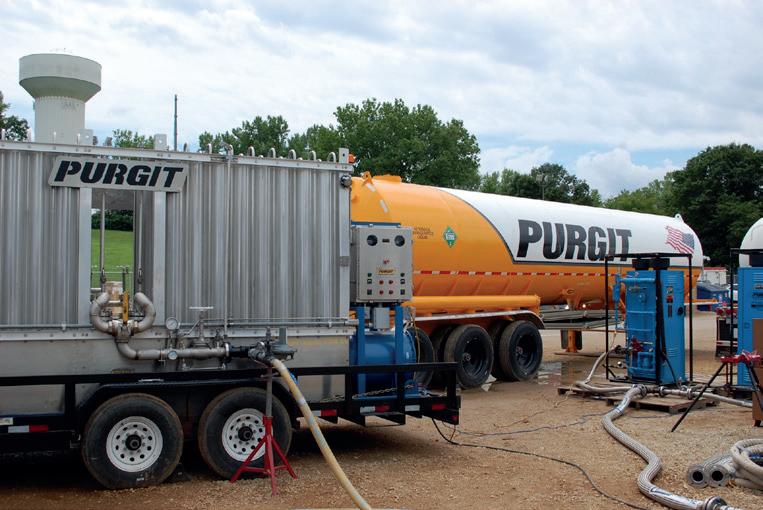
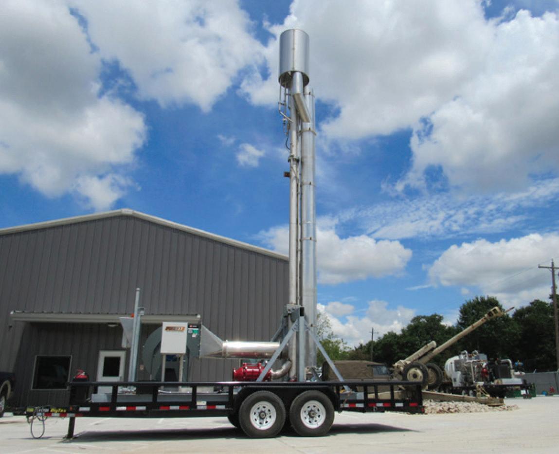
• Cryogenic Vaporizers for Liquified Gases
• Portable Enclosed Combustors
• Storage Tank Inert Gas Purging
• Liquid Nitrogen Truck Transports
• Specialization in NH3, LPG, and Natural Gas Tank Purges and Commissioning