


LEADING POWER SECTION TECHNOLOGY COMPLETIONS 1-11/16” thru 3-3/4” DRILLING 4-3/4” thru 11-3/4” MAGAZINE | AUTUMN 2023
Moving big things to zero with five key technologies


After 250 years engineering complex systems, we are ready for our biggest challenge: reducing emissions for essential industries. Our solutions are based on five technologies: producing green fuels in large volumes, making new engines to run on green fuels, retrofitting existing engines, capturing and processing CO2, and decarbonizing heat generation with heat pumps. Moving big things to zero is a big task but we have the experience, the technology, and the passion to get the job done.


www.man-es.com
Rudranil Roysharma, Frost & Sullivan, India, provides an overview of the upstream oil and gas sector in the Middle East, Africa and South Asia regions.

15 The Rewards Of Reservoir Simulation
Yamal Askoul, Baker Hughes, UK, explores the past and present of dynamic reservoir simulation, and details the benefits it is offering the oil and gas and energy transition sectors.
20 A Step Change In Stimulation
Thomas Jørgensen and Wissam Chehabi, Fishbones, Norway, discuss how operators are utilising the latest stimulation technology to enhance sustainability and efficiency.
25 Embracing Uncertainty

Atila Mellilo and Philip Neri, Halliburton Landmark, Denmark, explain how ensemble-based reservoir modelling is being used to maximise reservoir recovery.
28 Easing Hostile Relations
Gaurav Rohella, GlobalLogic, UK, explains how innovative technologies can help the upstream sector overcome challenges associated with hostile and hard-to-reach environments.

Front cover
With the worldwide oil and gas industry going deeper, faster, and farther, the need for specialised power section technology is clear. Abaco’s portfolio of elastomer technology extends the life of the power sections in diverse drilling and completion operations. Specialised power section diameters ranging from 1 – 11/16 in. – 11 – 3/4 in. deliver power, durability and maximised performance in corrosive, high temperature, high torque or high wear environments. Abaco delivers ‘nothing but power’ by offering customers an excellent drilling experience.

32 For Good Measure
Ming Yang, TÜV SÜD National Engineering Laboratory, UK, discusses the different methods used to measure oil-in-water, and the rise in online analysis techniques.
35
The Path Forward
Megan Pearl, Locus Bio Energy, USA, examines the role of biosurfactants and advanced testing in shale completions and explains why a multifaceted approach is vital in maximising oil recovery.


39
The Importance Of Advanced Engineering
Uday Godse, Wild Well Control, USA, discusses how advanced engineering can be used to optimise design and operations that augment well control engineering.
42 No Pressure
Danny Perez, Roman Che, Khoi Trinh, Chigozie Emuchay and Souhail Bouaziz, NOV, USA, discuss how new developments in friction reduction technology can widen horizons for operators.


Taking The Sting Out Of Splicing


Joachim Åkesson, Ace Well Technology, Norway, explains how the upstream industry can optimise splicing and reduce rig time.
Maintaining The Flame
Chris Addison, Advanced Energy, USA, and Michael Li, Wonder Engineering, Singapore, explain the key to ensuring a successful flare monitoring system.
ISSN 1757-2134 Copyright © Palladian Publications Ltd 2023. All rights reserved. No part of this publication may be reproduced, stored in a retrieval system, or transmitted in any form or by any means, electronic, mechanical, photocopying, recording or otherwise, without the prior permission of the copyright owner. All views expressed in this journal are those of the respective contributors and are not necessarily the opinions of the publisher, neither do the publishers endorse any of the claims made in the articles or the advertisements. Like us on Facebook Oilfield Technology Join us on LinkedIn Oilfield Technology Follow us on Twitter @OilfieldTechMag Autumn 2023 Volume 16 Number 03 Contents 03 Comment 05 World News
10 Mapping Out The Future Of MENA
us on Facebook Oilfield Technology Join us on LinkedIn Oilfield Technology Follow us on X @OilfieldTechMag LEADING POWER SECTION TECHNOLOGY COMPLETIONS 1-11/16” thru 3-3/4” DRILLING 4-3/4” thru 11-3/4” MAGAZINE AUTUMN 2023 The upstream oil and gas industry has long recognised and embraced the benefits of friction reduction tools (FRTs), which have facilitated reaching previously unattainable lateral lengths and achieving unprecedented drilling efficiency. These cutting-edge technologies have revolutionised the directional drilling sector and have improved performance of motor and rotary is important to acknowledge that implementing friction reduction tools necessitates operational adjustments and changes to drilling practices. Friction reduction tools generate friction breaking force, but this breaking force comes with price. As per the law of conservation of energy, energy cannot be created or destroyed; it can only be as drilling fluid flows through these tools, the internal components move relative to each other, altering the total flow area (TFA). Essentially, the hydraulic energy of the drilling fluid is transformed into axial mechanical energy, which used to break friction and improve weight transfer. The variation of the internal TFA within the tool translates into pressure drop, which each FRT will produce depending on the tool type and set up. Typically, the higher the pressure drop, the more up to a certain point to break friction. Theincreasedpressuredrop by FRTs undesirable for several reasons. It puts additional stress on pumps and surface equipment, and can limit the rig’s capacity to maintain desired flow rates during the drilling process total depth (TD). This pressure drop can also impact the ability to maximise downhole motor output, achieve optimum RSS hole cleaning capabilities. As operators drill longer lateral sections, they must, steadily, and over hundreds of feet, dial back on flow rates to maintain the system within the operational range of the surface pumping equipment. It is not feasible to include an FRT in the string to improve performance at the expense of lower differential at the motor, or hole cleaning long lateral sections (over 2.5 miles) opt to take the FRT out of the string for the last 1000 3000 of the lateral so that they can reach As a solution to this challenge, NOV developed new FRT that generates friction-breaking axial forces downhole without the need to produce pressure pulses or additional pressure drop to the drilling system. The AgitatorZP features tool design that enables operators to maintain optimal and maximum operational flow rates in the deepest parts of the lateral sections while getting maximum output represents a significant step change in operational improvements for operators in long lateral sections, as they can maximise motor as hole cleaning. An FRT that generates no pressure drop can also be useful in scenario where operators PRESSURE NO Danny Perez, Roman Che, Khoi Trinh, Chigozie Emuchay and Souhail Bouaziz, NOV, USA, discuss how new developments in friction reduction technology can widen horizons for operators. 42 43 42
Like
In 2022, TETRA treated and recycled over eight billion gallons of produced water for reuse in well operations. TETRA helps ensure consistent water quality and supply throughout completion operations—from automated water recycling systems, including our patented automated blending controller, to our on-the-fly treatment technologies that economically process diverse types of water to eliminate bacteria and sulfides prior to completion activities.


Not only is recycling water more sustainable and effective, it’s also cost efficient and a smart business practice, especially in water-scarce regions.

VISIT TETRATEC.COM/RECYCLE TO LEARN MORE.

2023 © TETRA Technologies, Inc. All Rights Reserved. TETRA WATER MANAGEMENT SOLUTION OFFERINGS Automation and Monitoring • Sourcing • Fresh and Produced Water Transfer • Pipeline Construction • Storage and Pit Lining • Treatment and Recycling • Oil Recovery • Blending and Distribution • Flowback and Testing
How do you save one billion gallons of water? RECYCLE.
Left: produced water; right: recycled produced water by TETRA.
Comment
Emily Thomas, Deputy Editor emily.thomas@palladianpublications.com
The ‘golden age of gas is over’ according to the The International Energy Agency (IEA). The company recently forecast that global oil demand will have peaked by 2030 as a result of the growing popularity of heat pumps, electric cars and buses, and the success of renewables in producing electricity. Europe’s deliberate move away from gas following the Russia/Ukraine conflict has also fuelled the notion that renewable technologies and low emissions fuels will be sufficient to meet future energy needs. Writing in The Financial Times, the agency warned of the economic, climate and financial impacts of new oil and gas projects.1
The article has divided opinion, with oil and gas producers in particular having criticised the IEA’s approach towards the energy transition. According to Reuters, the CEOs of oil giants Aramco and Exxon Mobil have expressed the importance of continued investment in oil and gas as a key factor in the transition to cleaner energy.2 OPEC Secretary General, HE Haitham Al Ghais, has echoed these sentiments in a statement following the release of the forecast, claiming that the global energy system has been “set up to fail spectacularly.” The statement continued: “[This narrative] does not take into account the technological progress the industry continues to make on solutions to help reduce emissions. Neither does it acknowledge that fossil fuels continue to make up over 80% of the global energy mix, the same as 30 years ago, or that the energy security they provide is vital.”3 Considering that many net zero technologies are still in their infancy, it is no surprise that a number of political figures are inclined to agree that the energy transition should not be rushed.
Prime Minister of the United Kingdom, Rishi Sunak, recently made the decision to ease UK climate targets, pushing back on a range of measures, from taxing meat consumption, to discouraging foreign travel by raising air fares. A nine-year delay has also been placed on the ban of fossil fuels being used to heat off-gas-grid homes, whilst a ban on new petrol-only cars has been suspended, with Sunak claiming that net zero will be met in “a proportionate and pragmatic way.”4 This follows the UK government’s recent announcement that new licences would be granted for oil and gas exploration in the North Sea. Sunak defended this decision, claiming that using the energy we have at home is consistent with a transition to net zero.5 The subseqeuent approval of the controversial Rosebank project, therefore, was to be expected.
Acquired by Equinor in 2019, Rosebank is the largest undeveloped oil and gas field in the UK, located west of the Shetland Islands, with an estimated 300 million bbl of potentially recoverable reserves. The development of the field is highly contentious, yet the proposed advantages in terms of UK energy security cannot be ignored. Furthermore, Equinor plans for the field to be developed with a redeployed, refurbished Floating Production Storage and Offloading vessel (FPSO) tied to a subsea production system, which will be electrification-ready and able to be powered from shore. The operator claims that this has the potential to reduce production emissions from the field by over 70%. The North Sea currently produces oil at around 20 kg CO2/bbl; post-electrification, it is believed that Rosebank could produce oil at 3 kg CO2/bbl. An estimated £8.1 billion of direct investment into UK businesses is also an undeniable advantage of Rosebank, as is the promise of 1600 jobs created for highly-skilled oil and gas workers.6

While the world continues to battle over the right approach to net zero, and fossil fuels continue to represent a large percentage of the global energy mix, the best thing oil and gas producers can do is aim to provide energy security whilst decarbonising their operations. For now, this can help to bridge the gap between a climate disaster and a rush towards renewables.
*References are available upon request.
Autumn 2023
Contact us
Editorial
Managing Editor: James Little james.little@palladianpublications.com
Senior Editor: Callum O’Reilly callum.oreilly@palladianpublications.com
Deputy Editor: Emily Thomas emily.thomas@palladianpublications.com

Editorial Assistant: Jack Roscoe jack.roscoe@palladianpublications.com
Design
Production: Kate Wilkerson kate.wilkerson@palladianpublications.com
Sales
Sales Director: Rod Hardy rod.hardy@palladianpublications.com
Sales Manager: Chris Lethbridge chris.lethbridge@palladianpublications.com
Sales Executive: Daniel Farr daniel.farr@palladianpublications.com
Website
Digital Administrator: Leah Jones leah.jones@palladianpublications.com
Digital Content Assistant: Kristian Ilasko kristian.ilasko@palladianpublications.com
Events
Events Manager: Louise Cameron louise.cameron@palladianpublications.com
Digital Events Coordinator: Merili Jurivete merili.jurivete@palladianpublications.com
Marketing
Administration Manager: Laura White laura.white@palladianpublications.com
Reprints: reprints@palladianpublications.com
Palladian Publications Ltd, 15 South Street, Farnham, Surrey GU9 7QU, UK Tel: +44 (0) 1252 718 999
Website: www.oilfieldtechnology.com

Autumn 2023 Oilfield Technology | 3
Always victorious.
Drilling challenges are becoming tougher, and the demands on drill bits are rising.
ReedHycalog’s new premium Pegasus™ series drill bits combine industr y-leading technologies to overcome the harshest and most challenging drilling applications, including geothermal. Where existing fixed-cutter, hybrid, and roller cone bits have fallen short of their target, Pegasus drill bits are here to eliminate the competition and deliver next-level bit performance.
NOV Pegasus Series Drill Bits

© 2023 NOV Inc. All Rights Reser
ved.
World news
Rystad Energy: North Sea oil and gas industry booms with increasing production and investments

Norway and the UK have overcome recent challenges and are on course to achieve significant milestones due to notable increases in investments, exploration success and production, according to Rystad Energy. Solid oil and gas production from the region is also providing indispensable resources to Europe and the rest of the world navigating through the energy transition.
Investments in Norway’s oil and gas industry are expected to reach a record-high of about US$21 billion in 2023. This comes as several key projects have been approved in recent years, driven by the country’s temporary tax regime, which was introduced to incentivise spending on the Norwegian continental shelf.
“With an impressive growth rate this year, the total investments in the Norwegian oil and gas industry are projected to surpass the record set in 2013, when total investments reached about US$19 billion. The investments in 2023 are expected to reach a new all-time high, and this significant increase in investment would mark a new milestone in the oil and gas sector in Norway,” affirms Emil Varre Sandoy, Upstream Vice President at Rystad Energy.
This increase in investment is a positive development after several lean years in the industry and will be particularly welcomed by the oilfield service sector. This investment in the sector is essential for maintaining a strong service industry while it undergoes a gradual transition towards alternative energy sources.
Despite a decline of almost 15%, from a peak of nearly 4.6 million boe/d in 2004, Norwegian oil and gas production is set to rise again. By 2025, production might rise back towards peak levels as a result of increased focus on gas production and new projects in the pipeline. These volumes will be produced with one of the world’s lowest CO2 footprints and reduce Europe’s dependency on Russian hydrocarbons.
BP signs MOU with Subsea Integration Alliance to enhance integrated subsea project performance
BP has signed a Memorandum of Understanding (MoU) with Subsea Integration Alliance aimed at developing a framework to enhance integrated subsea project performance. The agreement with the alliance, which comprises Subsea7 and OneSubsea™, an SLB company, will combine the three companies’ skills, knowledge and experience across a global portfolio of projects.
The agreement will combine BP’s experience to frame, build and execute projects with the alliance’s capability to deliver integrated subsea production systems (SPS) and subsea umbilical, riser and flowline (SURF) systems. The team will work together, from concept development through the full field lifecycle to support project delivery through new ways of working and an innovative commercial model.
A new team will be formed to oversee and manage activities across the programme, with a focus on safety, quality and subsea project performance.
Ewan Drummond, BP’s SVP of projects, said: “The members of Subsea Integration Alliance have been a key supplier of BP for decades, and by combining our resources and knowledge, we can bring significant benefits to our customers and our stakeholders. Together we can safely deliver projects with improved project schedules, reducing our total cost of ownership and harnessing synergies through a collaborative one-team mindset. We look forward to getting to work.”
Olivier Blaringhem, CEO of Subsea Integration Alliance, said: “This agreement marks a step change in how our highly collaborative teams will work together to achieve shared objectives for mutual value. Together with BP, we will deliver lower carbon energy to the world through enhancing long-term subsea performance.”
The MoU was signed at an official ceremony in London on 22 September 2023, that was attended by Ewan Drummond, Olivier Blaringhem, Louise Jacobsen Plutt, BP’s SVP of procurement, Kristian Siem, Subsea7 Chairman, John Evans, Subsea7 CEO, Steve Gassen, SLB President of Production Systems, and Mads Hjelmeland, SLB Director of Subsea Production Systems.
Autumn 2023
United Kingdom
Equinor and Ithaca Energy have taken the final investment decision to progress Phase 1 of the Rosebank development on the UK Continental Shelf (UKCS), investing US$3.8 billion.
The North Sea Transition Authority (NSTA) granted consent for the development of the field on 27 September.
“Developing the Rosebank field will allow us to grow our position as a broad energy partner to the UK, while optimising our oil and gas portfolio, and increasing energy supply in Europe. Rosebank provides an opportunity to develop a field within the UK Continental Shelf which will bring significant benefits to Scotland and the wider UK,” says Geir Tungesvik, Executive Vice President Projects, Drilling and Procurement at Equinor.
The Rosebank field is located around 130 km north-west of Shetland in approximately 1100 m of water depth. Total recoverable resources are estimated at around 300 million boe, with Phase 1 targeting estimated 245 million boe.
The field will be developed with subsea wells tied back to a redeployed Floating Production Storage and Offloading vessel (FPSO), with start-up planned in 2026 – 2027. Oil will be transported to refineries by shuttle tankers, while gas will be exported through the West of Shetland Pipeline system to mainland Scotland.
USA
TGS has announced a northern extension to its previously announced Pontiac 3D Survey in the Midland Basin. The extension increases the size of the Pontiac 3D from 167 m2 to a total of approximately 267 m2 and is located in Midland, Ector, Upton and Crane counties, Texas, US.
The northern extension of the Pontiac 3D sits on the western edge of the Midland Basin and encompasses historical production from Sprayberry and Wolfcamp intervals along with significant accumulations in deep-seated structures in the Devonian and Ellenburger formations.
In brief w Autumn 2023 Oilfield Technology | 5
World news
Diary dates
02 - 05 October 2023
ADIPEC 2023
Abu Dhabi, United Arab Emirates adipec.com
16 – 18 October 2023
SPE ATCE 2023 Texas, USA atce.org
20 – 22 February 2024
Subsea Expo
Aberdeen, UK www.subseaexpo.com
Web news highlights
Ì Bozhong 28-2 south oilfield second adjustment project commences production
Ì Norwegian Petroleum Directorate (NPD) and the Petroleum Safety Authority (PSA) to undergo name change in 2024
Ì Arena Energy awarded seven blocks on Gulf of Mexico Shelf
To read more about these articles and for more event listings go to:
www.oilfieldtechnology.com
Shenzi North project has commenced production in the Gulf of Mexico

The Woodside-operated Shenzi North project has commenced production in the deepwater US Gulf of Mexico.
Shenzi North is a two-well subsea tieback that takes advantage of the existing Shenzi infrastructure to increase production capacity of the asset.
The project, on which a final investment decision (FID) was taken in July 2021, achieved production ahead of targeted first oil in 2024. Woodside CEO, Meg O’Neill, said the start-up of Shenzi North further demonstrated the value of Woodside’s US Gulf of Mexico assets, acquired as part of the merger with BHP’s petroleum business in 2022. “First production from Shenzi North shows how we are leveraging existing infrastructure to increase production and provide attractive returns from our Gulf of Mexico business.”
“Taking the project from FID to first oil in 26 months is a great achievement. I commend the project team on safely bringing this resource into production well ahead of schedule,” she said.
Woodside holds a 72% interest in the Shenzi conventional oil and gas field as operator and Repsol holds the remaining 28% interest. The field is located approximately 195 km off the coast of Louisiana in the Green Canyon protraction area. Shenzi was discovered in 2002 and first production of oil and natural gas occurred in 2009.
The Shenzi platform produces both oil and gas with a production capacity of 100 000 bpd. Crude oil and natural gas produced from the field is transported to connecting pipelines for onward sale to Gulf Coast customers.
TWMA secures long-term contract with Equinor
TWMA has secured a long-term contract with Equinor. The 10-year agreement will see TWMA extend its global drilling waste management services to Equinor’s operations, allowing the company to process its drilling waste safely and sustainably.
The contract is inclusive of five scopes of work, including bulk transfer, slop treatment, swarf treatment, skip and ship, and TWMA’s offshore processing technology, the RotoMill®.
Jan Thore Eia, TWMA Business Development Manager in Norway, said: “Our collaboration with Equinor marks a significant milestone for TWMA. This collaboration is a testament to our expertise in providing innovative and sustainable drilling waste management solutions. We look forward to delivering these solutions to Equinor and supporting drilling operations in Norway.”
Halle Aslaksen, TWMA CEO, said: “This contract underlines the impressive growth we have witnessed across our Norwegian operations. We are dedicated to delivering the best environmental practices in drilling operations and I look forward to developing our relationship in the coming years.”
Wood and Harbour Energy agree strategic partnership
Wood and Harbour Energy have entered into a new strategic partnership for UK North Sea operations agreeing a new master services agreement (MSA) and associated contracts valued at around US$330 million.
Under this new agreement, Wood will provide engineering, procurement and construction (EPC) and operations and maintenance (O&M) services, including digital and decarbonisation solutions, for a number of Harbour’s offshore assets critical to UK energy security.
The strategic partnership will run for an initial term of five years, with five one-year extension options covering Harbour’s operated assets, including its J-Area, Greater Britannia Area, Solan and AELE (Armada, Everest, Lomond and Erskine) hubs.
Steve Nicol, Wood’s Executive President of Operations, said: “We are incredibly proud to have been selected and trusted by Harbour Energy to partner with them across their North Sea assets. We share a commitment to ensuring safe, reliable and sustainable energy production and are confident our integrated digital solutions and world-leading engineering, operations and decarbonisation expertise will enable Harbour to maximise their investment and ensure the UK continues to have the energy mix it needs.”
6 | Oilfield Technology Autumn 2023
Autumn 2023

World news
Aker BP awarded Exploration Innovation Prize for its ‘exploration robot’
Aker BP has been awarded the Exploration Innovation Prize for the development of machine learning models for use in exploration work. The company’s exploration department is already using the models, often referred to as the ‘exploration robots.’
The machine learning models that have been developed can assist geologists and geophysicists in reconstructing missing well logs, making lithology predictions, calculating shale content, and mapping potential undiscovered reservoir areas. The solution can also provide an impartial assessment of log quality.
The prize is presented by Geopublishing and is awarded during the NCS Exploration Conference.
The jury was impressed that the team has succeeded in creating a tool that is actually used and streamlines daily work.
Peder Aursand, Value Stream Manager and data scientist at Aker BP, presented the ‘exploration robot’ during the conference. He highlighted three factors that have been crucial to their success.
“Firstly, we have focused on making the models work for the exploration team, not the other way around. Secondly, we have included explanations and quantification of inherent uncertainty as standard in the models. And we have made the models available in tools and software that the exploration team is already familiar with and uses daily,” says Aursand.
He received the award along with several representatives from the team that developed the exploration robot. In addition to Aursand, the team consists of Tanya Kontsedal, Kjetil Westeng, Yann Van Crombrugge, Christian Lehre, Martine Dyring Hansen, Peyman Rasouli, and Etienne Sylvain Peysson.
DNO makes discovery in the Norwegian North Sea
DNO has announced a gas condensate discovery on the Norma prospect in the Norwegian North Sea license PL984 in which the company holds a 30% operated interest.
Preliminary evaluation of the discovery indicates gross recoverable resources in the range of 25 – 130 million boe on a P90 – P10 basis, with a mean of 70 million boe, in a Jurassic reservoir zone with high quality sandstones. Located 20 km northwest of the Balder hub and 30 km south of the Alvheim hub, Norma is situated in an area with extensive infrastructure in the central part of the North Sea, with tie-back options offering potential routes to commercialisation.
Also within the same license, DNO has identified additional exploration prospects that have been considerably de-risked by the Norma results.
“Coming on the heels of our six Troll-Gjøa area discoveries since 2021, three of which were made this year including Carmen, Heisenberg and Røver Sør, Norma opens up an exciting new play for DNO in the North Sea,” said Executive Chairman Bijan Mossavar-Rahmani. “At the risk of hoodooing our crack explorationists, the string of recent discoveries validates DNO’s offshore Norway exploration strategy,” he added.
Saipem awarded offshore contracts in Côte d’Ivoire and Italy
Saipem has been awarded two new contracts for offshore activities in Côte d’Ivoire and Italy for an overall amount of €850 million.
The first contract has been awarded to Saipem by Eni Côte d’Ivoire and its partner Petroci. It is a subsea umbilicals, risers and flowlines (SURF) contract for the development of the Baleine Phase 2 project, which takes its name from the oil and gas field, located offshore Côte d’Ivoire at a 1200 m water depth.
The scope of work encompasses the engineering, procurement, construction and installation (EPCI) of approximately 20 km of rigid lines, 10 km of flexible risers and jumpers and 15 km of umbilicals connected to a dedicated floating unit. The installation works will be carried out by Saipem’s offshore construction vessels and will take place in 2024.
With this new award, Saipem brings a further strategic contribution to the history of the Baleine field and strengthens its presence in Côte d’Ivoire. Saipem contributed to the drilling activities of Baleine Phase 1 by deploying the Saipem 10 000 and Saipem 12 000 vessels, followed up by the execution of two contracts for Baleine Phase 1 in fast-track mode.
The second contract has been awarded to Saipem, through a temporary association of companies with Rosetti Marino and Micoperi, by Snam Rete Gas for the construction of the facilities for the new floating storage and regasification unit (FSRU) to be located in the Adriatic Sea offshore Ravenna, Italy.

The project consists of the EPCI of a new offshore facility, linked to the existing one, for the docking and mooring of the FSRU, to be connected to shore via a 26 in. offshore pipeline 8.5 km in length, plus a 2.6 km onshore pipeline and a parallel fibre optic cable. The shore crossing will utilise a microtunnelling system to minimise environmental impacts. Offshore operations will be executed by Saipem’s pipelay barge Castoro 10.
ABB supports Well Done Foundation to tackle orphan oil and gas wells

ABB will provide financial support to the Well Done Foundation, a non-profit organisation that tackles the massive environmental problem of millions of leaking orphan oil and gas wells across the United States. The three-year financial partnership will support the organisation in carrying out their critical work of detecting, plugging and monitoring leaking wells.
The Well Done Foundation works to cap orphan oil and gas wells that have been deactivated and no longer have legal owners responsible for their care. Due to their age and deteriorated condition, the wells can leak methane and other harmful greenhouse gases. ABB’s emissions monitoring technology is central to the work carried out by the foundation as both parties align to help tackle harmful emissions.
“ABB’s partnership brings immense value to our campaign to fight climate change through the plugging of orphaned oil and gas wells,” said Curtis Shuck, Chairman of the Board of the Well Done Foundation. “The financial support is obviously most welcome, and it is ABB’s technology and expertise in emissions monitoring that are helping us to fight climate change one well at a time.”
Autumn 2023
8 | Oilfield Technology Autumn 2023
Learn More


MAPPING OUT
Energy is considered the most critical ingredient for the development of any economy. For decades, the Middle East and North Africa (MENA) region has played a significant role in the global energy ecosystem and has supported industrialisation and economic growth in several countries around the world. The geological framework of the region favours the generation and accumulation of large oil and gas reserves.
The region is home to some of the world’s largest conventional onshore and offshore oil and gas fields. The most prominent fields in the region include Ghawar and the Safaniya oilfields in Saudi Arabia, the Burgan oilfield in Kuwait, the Rumaila oilfields in Iraq, and the South Pars/North Dome gas field, co-owned by Iran and Qatar. The North African oil and gas landscape revolves primarily around three producer countries: Algeria, Libya, and Egypt.
All conventional basins across the world also contain large volumes of shale. It is estimated that the MENA region has 2547 ft3 of shale gas reserves.1 Some Middle Eastern countries such as Saudi Arabia, UAE, Bahrain, and Oman are developing shale oil and gas fields in the region, such as Khazzan, South Ghawar, Jafurah, and Rub’ Al Khali.
Regulations and NOCs
The energy and resources sector is the cornerstone of economic growth and development for Middle Eastern and North African countries. Since oil and gas related activities are the primary source of revenue for the government, it is a strictly regulated sector. National oil companies (NOCs) are responsible for developing the oil and gas sector in their respective countries. A few of the prominent NOCs within the region are:
Ì Saudi Aramco.
Ì National Iranian Oil Company.
Ì Iraq National Oil Company.
Ì Kuwait Petroleum Corporation.
Ì Qatar Energy.
Ì Sonatrach Algeria.
Ì OQ Oman.
Ì National Oil Company Libya.
Ì ADNOC.
NOCs enter strategic partnerships with international oil companies (IOCs) such as BP, Chevron, Shell and Exxon Mobil, to name a few, to develop oil and gas fields within the MENA region. While IOCs get access to the country’s oil and

10 |
Rudranil Roysharma, Frost & Sullivan, India, provides an overview of the upstream oil and gas sector in the Middle East, Africa and South Asia regions.
THE FUTURE OF MENA

| 11
gas reserves, NOCs benefit from IOCS’ technological prowess and financial capabilities.
Another important stakeholder in the value chain is the oilfield service (OFS) providers. These companies provide necessary products and services to explore and develop wells and further production of oil and gas from those wells. Notable international OFS companies in the region are Schlumberger, Baker Hughes, Halliburton, and Weatherford. When doing business with the Middle East NOCs, suppliers and service providers need to demonstrate compliance with the in-country value addition requirements that have been introduced by Aramco (IKTVA), ADNOC (ICV), and Oman’s Ministry of Oil and Gas (ICV), with Kuwait and other producer nations likely to follow suit.2
MENA as a backbone for the world’s energy ecosystem
Oil and gas producers in the MENA region have been the backbone of the global energy system. The MENA region holds about 57% of the world’s proven oil reserves and about 41% of natural gas resources.3


Historically, the region has contributed to about 37% of the world’s total oil supply and approximately 35% of the world’s total gas supply.4
Crude oil production in the MENA region was approximately 33 million bpd in 2022, amounting to about 33% of the total oil produced in the world. Natural gas production in 2022 was about 963 billion m3, roughly 23% of the total gas produced globally.5,6
Currently, the region accounts for approximately 50% of oil exports and 15% of natural gas exports worldwide.7 Major oil producers within the region include Saudi Arabia, Iraq, UAE, Kuwait, and Iran. Gas production in the MENA region is dominated by Iran, Qatar, Saudi Arabia, Algeria, Egypt, and UAE.
Strong outlook for the upstream sector in the MENA region
MENA’s five-year (2022 – 2026) energy investment portfolio is comprised of a total investment of US$879 billion, which is a 9% increase over the investment projection for 2021 – 2025.8 Of all the projects in the pipeline for implementation, about 30% are in the execution phase. The increase in project expenditure is spearheaded by the Gulf Cooperation Council (GCC), with committed projects making up more than 45% of the Gulf States’ total energy investments. National oil companies in the region have committed investments in the upstream sector to increase the country’s oil and natural gas production in the coming years:
Ì Saudi Aramco aims to increase its crude oil production capacity to 12.3 million bpd by 2025,9 thereby bringing additional output to meet global energy requirements. The plan is to further raise the production capacity to 12.7 million bpd by 2026 before reaching 13 million bpd by 2027. The kingdom plans phase-wise expansion of the nation’s production capacity – the Dammam field is forecasted to yield an additional 75 000 bpd by 2024, and the offshore Marjan and Berri fields are set to provide another 300 000 bpd and 250 000 bpd by 2025. The Zuluf field expansion is projected to add 600 000 bpd by 2026 and the Safaniyah development is set to increase production by 700 000 bpd by late 2027.
Ì The ADNOC board recently endorsed plans to bring forward the company’s 5 million bpd oil production capacity expansion to 2027 from a previous target of 203010 to meet rising global energy demand. The ADNOC board has approved a five-year business plan and a capital expenditure of 550 billion AED (US$150 billion) to enable the firm’s growth strategy for the period 2023 – 2027. Further, ADNOC will introduce low-carbon solutions and an international division centered on new energies, gas, LNG, and chemicals.
Ì Qatar Energy has planned expansion of the North Field to ramp up its liquefaction capacity from 77 million tpy to 126 million tpy by 2027.11 The project will boost Qatar’s position as the world’s top LNG exporter and help guarantee long-term supplies of gas to Europe as the continent seeks alternatives to Russian flows.
Ì The Middle East oil and gas landscape has always been the focal point of global energy dynamics.
12 | Oilfield Technology Autumn 2023
Figure 1. Distribution of the world’s proven oil and gas reserves in 2020. Source: BP statistical review of World Energy, 2021.
Figure 2. 2022 revenue (US$ billion) of the MENA NOCs. Note: Revenue numbers are for 2022 except for National Iranian Oil Company and Iraq National Oil Company. * 2017 revenue; 2019 revenue.
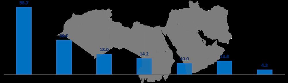
Figure 3. Oil production of key producer countries in MENA in 2022 (million bpd). Source: International Energy Agency.
Mastering Well Control Challenges:

Where Advanced Engineering Ensures
Safe Solutions
Wild Well Control is at the forefront of cutting-edge engineering and well control services within the oil and gas industry. Prioritizing safety and ingenuity, our experienced professionals promptly handle wellbore complications, demonstrating expertise in intricate situations.
Our distinguished rapid response encompasses sealing maneuvers in the harshest of circumstances. Moving beyond conventional drilling, Wild Well's skilled engineering unit partners with clients to reinstate standard drilling conditions. Our proficient well control staff guarantees the secure management of well control occurrences, drawing upon extensive proficiency in both established and innovative methodologies.

Contact us for all your well control needs. +1 281.784.4700 / WILDWELL.COM
The sector has recently gone through significant challenges and changes, and, as a result, future investment commitments in the region have become more diverse, with a focus on LNG, more complex offshore projects, renewables, and decarbonisation. The trend aligns with the energy transition plan for most global economies.
Energy security and low-carbon investments may pose a threat to the MENA upstream sector
The ongoing Russia-Ukraine tension may pose a threat to the MENA upstream sector. The European Commission has announced plans to make the continent independent of Russian fossil fuels through the widespread adoption of renewable energy (RE) and diversification of natural gas supplies. Frost & Sullivan identified five growth opportunities that will shape the global energy landscape in the coming years:
Ì Energy security will be the foremost priority for most nations.
Ì Renewables adoption will no longer be by choice but out of necessity.
Ì Fossil fuel prices will become a key geo-political lever for the energy-supplying nations.
Ì Coal and oil will be reduced to regional fuels.
Ì Demand for natural gas, a transitioning fuel, will depend on its affordability.
Fossil fuel importers are always vulnerable to supply disruption and price volatility; therefore, tapping into a country’s indigenous resources for energy needs will become a priority in the coming decades.
As countries reduce dependence on energy imports, the upstream sector, which is dominated by the MENA region, may be affected as supply may outstrip demand. Further, a demand reduction would create a stagnant low-price environment in the oil market that could impact the upstream operators and the producing nations.
Energy transition and integration of renewables
Blue and green hydrogen
Hydrogen is gaining significance as a clean energy vector. Both blue hydrogen (produced from natural gas with carbon capture) and green hydrogen (produced via electrolysis using RE) are seen as key pillars
of the energy transition within the region. Initiatives of select MENA countries towards the implementation of a hydrogen-enabled economy12 are outlined below:
Ì Saudi Arabia: in 2021, Saudi Arabia launched the Saudi Green Initiative that aims to develop substantial green hydrogen and green ammonia production around Neom. When completed, the project would encompass the world’s largest utility green hydrogen facility. Further, the Green Initiative includes thirteen RE projects with total capacity addition (GW) targets of 11.3 GW that could reduce around 20 million tpy of carbon emissions.
Ì Oman: Oman recently introduced a new Green Hydrogen Strategy, envisioning US$140 billion in investment by 2050. The goal is to produce 1 – 1.25 million tpy of green hydrogen by 2030, increasing production to 3.25 – 3.75 million t by 2040, and 7.5 – 8.5 million t by 2050. Oman is also working on a project for a green steel plant powered by hydrogen, with a yearly production of 5 million t. The products from this plant would be exported to other Middle Eastern countries, Europe, Japan, and Asia.
Ì Qatar: Qatar has initiated a project to establish the largest blue ammonia facility worldwide and is actively acquiring international renewable companies. Qatar Investment Authority (QIA) is also exploring the possibility of providing support for projects involving green ammonia and fuel for navigation in Egypt.
Focus on renewable energy capacity additions
Several MENA countries are incorporating renewables, particularly solar and wind energy, into their power generation mix. Some of these countries have set ambitious RE capacity addition targets by 2030,13 – 16 which is driven by decreasing renewable technology costs and the global shift towards cleaner energy sources. A large part of this RE would be used in green hydrogen production which would then be exported to various parts of the world and also be used in the production of green ammonia, green steel, green methanol, and so on.

Energy storage solutions
The integration of energy storage solutions, particularly battery storage, is gaining momentum. Energy storage helps in managing the intermittency of renewable sources, enhances grid stability, and facilitates the dispatchability of power.
Electrification of industries
There is a growing interest in electrifying energy-intensive industries such as petrochemicals and refining, which are heavily reliant on fossil fuels.
Conclusion
The global energy industry is going through a huge transformation, and the future of the MENA oil and gas sector is one to watch. It will be interesting to see how the regional NOCs navigate these interesting and challenging times and usher in a low-carbon environment.
References
For a full list of references please visit: https://bit.ly/3sV7M5l
14 | Oilfield Technology Autumn 2023
Figure 4. Natural gas production of key producer countires in MENA in 2022 (billion m3). Source: International - US Energy Information Administration (EIA). Note: The figures for Bahrain, Libya and Iraq are 2021 production values.
Figure 5. Renewable energy capacity addition (GW) targets of select MENA countries by 2030. * long-term renewable energy capacity addition target.
The rewards of reservoir simulation

Yamal Askoul, Baker Hughes, UK, explores the past and present of dynamic reservoir simulation, and details the benefits it is offering the oil and gas and energy transition sectors.
Anumber of industries rely heavily on technological advancements that lay the foundation for future developments. The oil and gas and energy transition sectors are no exception. Dynamic reservoir simulation in the oil and gas industry dates back to the 1960s when computer-based modelling first gained traction. Initially, these simulations were limited to simple models that provided basic insights into process behaviour. However, advancements in computing power and software capabilities propelled dynamic reservoir simulation to evolve into a sophisticated tool capable of replicating real-time operational scenarios.
In the 1970s, companies in the energy sector recognised the potential of dynamic reservoir simulation, leading to a race in its development and investigation. This era witnessed the introduction of comprehensive process simulation software packages that offered dynamic modelling capabilities. Engineers and operators were now able to simulate complex conditions and predict reservoir behaviour, specifically in terms of production output. As computer technology continued to advance in the 1980s and 1990s, dynamic reservoir simulation became increasingly sophisticated, with integrated advanced
| 15
control systems, real-time data acquisition, and more accurate modelling techniques. These advancements empowered operators to optimise process performance, evaluate safety measures, and improve operational efficiency.
Dynamic reservoir simulation at present

In the 21st century, dynamic reservoir simulation applications in the oil and gas industry experienced a rapid expansion, supported by improved computing performance and high-fidelity models. Companies are able to simulate complex phenomena such as multiphase flow, heat transfer, and fluid dynamics, with greater accuracy. This enables the combination of real-time data integration and dynamic simulation, resulting in the creation of powerful predictive models.
Building a model
The time required to build a dynamic reservoir model in the oil and gas and energy transition sectors can vary significantly due to various factors. These factors include data collection and preparation, data analysis and interpretation, reservoir characterisation, reservoir simulation model construction, model calibration and history matching, and model validation and uncertainty analysis. Additionally, considerations such as software capabilities, computational resources, and the expertise of the team involved play a crucial role. In general, the time required to build a dynamic reservoir model can range from several weeks, to months or years depending on these factors.

This is a general timeline and actual project durations can vary significantly based on the specific circumstances of each reservoir and project.
The process of building a robust dynamic reservoir model begins with reservoir characterisation. This involves building a geological model that accurately represents the subsurface reservoir.
Geoscientists employ seismic interpretation, well-log analysis, and reservoir rock characterisation techniques to unravel the geological structures and rock properties, and engineer support to understand fluid properties within the reservoir.
Seismic interpretation entails mapping subsurface structures using seismic data, enabling the identification of fault lines, stratigraphic layers, and hydrocarbon-bearing formations. Well-log analysis assists in evaluating porosity, permeability, lithology, and fluid saturations at different depths. Additionally, reservoir rock characterisation involves laboratory testing of core samples to determine essential rock properties like porosity and permeability that can be contrasted against log analysis results to have a calibration.
These characterisations play a vital role in building a detailed representation of the reservoir by capturing its complexity and heterogeneity, which are essential for an accurate and dynamic reservoir model.
After the completion of the geologic model, the next step involves constructing a static model, which discretises the reservoir into a grid or cell system, enabling numerical simulation of fluid flow. Each cell within the grid system represents a small volume within the reservoir. Properties such as porosity, permeability, and fluid saturation are assigned to each cell based on the reservoir characterisation data.
The grid blocks can be either uniform or non-uniform, depending on the desired resolution and computational efficiency. In some cases, upscaling techniques are employed to represent the reservoir at a coarser scale, while maintaining the critical flow behaviour. The static model acts as the initial representation of the reservoir’s properties and forms the foundation for dynamic simulations.
The required equation and data for dynamic reservoir simulation
The heart of dynamic reservoir modelling lies in fluid flow simulation, which involves governing equations for fluid flow through porous media. These equations are typically derived from Darcy’s law and mass conservation principles. Major laws used in reservoir simulation include:
Ì Conservation of mass: flow equations for flow in porous materials are based on a set of mass,
16 | Oilfield Technology Autumn 2023
Figure 1. Multilateral well location.
Figure 2. Improvement in oil production total and reduction of unwanted fluid.
Optimum Strength elastomer formulated for high torque and designed for increased reliability in high solids drilling applications
Maximum Wear elastomer designed to deliver increased durability and high torque in high performance drilling applications


High Temperature elastomer for applications requiring high power output and excellent fatigue life at elevated downhole temperatures
Elastomers that deliver nothing but power

No matter what you are drilling through, or what well you are completing, we have the right elastomer compounds for the job. Specifically formulated to deliver the power, durability and maximized performance you demand.
See how we deliver nothing but power sections at Abacodrilling.com
© 2023 Abaco Drilling Technologies. All rights reserved.
LEADING POWER SECTION TECHNOLOGY
momentum and energy conservation equations, along with constitutive equations for the fluids and the porous material involved.
Ì Conservation of momentum: the governing equations for momentum, usually described by the Navier-Stokes equations, are simplified for low-velocity flow in porous materials, and are instead described by the semi-empirical Darcy’s equation. This equation is used in the case of a single-phase, one-dimensional, horizontal flow.
Ì Conservation of energy: referred to as the first law of thermodynamics, this principle states that energy can neither be created or destroyed; it can only be transformed from one form to another. This principle serves as the cornerstone of dynamic reservoir simulation, ensuring the preservation of energy throughout the simulation process.
In addition, a dynamic reservoir model needs accurate and reliable input data such as fluid properties, rock properties, pressure differentials, and production/injection rates. Numerical algorithms discretise the reservoir grid and iteratively solve the equations, predicting fluid flow behaviour over time. The simulations provide valuable insights into pressure distributions, fluid movement patterns, and production/injection rates over time. By simulating different scenarios, engineers can assess the reservoir’s response to various production strategies and optimise field development plans.
Implementing dynamic reservoir simulation
Dynamic reservoir simulation is particularly beneficial in the following scenarios:
Ì Real-time decision making: dynamic reservoir simulation enables engineers to make informed, real-time decisions by providing up-to-date reservoir performance data. It allows for better prediction of fluid movement, pressure changes, and production behaviour, leading to more accurate and timely decision making.
Ì Production optimisation: by simulating different production scenarios, engineers can identify optimal well placements, well configurations, and production strategies. This optimisation can maximise hydrocarbon recovery while minimising costs, leading to improved reservoir management and increased profitability.
Ì Risk reduction: dynamic reservoir simulation facilitates risk analysis and mitigation. It helps identify potential challenges such as water breakthrough, gas coning, or reservoir compartmentalisation, enabling engineers to design effective mitigation strategies and reduce uncertainty during field development.
Ì Geothermal reservoir assessment: thermal dynamic simulation plays a vital role in predicting crucial information related to heat extraction (enthalpy per day) and recharge rates between producers and injectors. By understanding pressure and thermal fronts, as well as cooling fronts, the simulation provides valuable insights into the reservoir’s energy capacity and performance limits. This essential data helps in planning the design of heat exchangers, surface facilities, and commercial strategies more effectively, ensuring optimal utilisation of the geothermal resource and sustainable project development.
Ì Carbon capture, utilisation, and storage (CCUS) dynamic simulation: dynamic reservoir simulation plays an important role to understand the behaviour of CCUS processes and their implications for long-term carbon management. For carbon capture and storage (CCS), the process consists of injecting carbon dioxide (CO2) into geological formations, such as
depleted oil and gas reservoirs or saline aquifers. The simulation helps to understand reservoir pressure changes, migration of CO2 within the formation, and potential risks like induced seismicity and leakage. Understanding these dynamics is crucial for assessing storage capacity and ensuring the long-term stability of the storage site. On the other hand, the process for CCUS also considers capturing CO2 emissions from fossil power generation and industrial processes for storage and utilisation in underground oil reservoir. Dynamic reservoir simulation also helps to predict the interaction between the injected CO2 and liquid hydrocarbon over time and understand whether injecting CO2 will have any benefit to recover more oil.
Ì Enhanced reservoir management: through dynamic reservoir simulation, engineers can monitor reservoir performance and evaluate the impact of operational changes in real time. This information assists in reservoir management, ensuring long-term sustainability and prolonged production life.
Ì Complex reservoirs: when dealing with complex geological structures, heterogeneous reservoirs or challenging fluid behaviour, dynamic reservoir simulation offers valuable insights into the behaviour of the reservoir, helping optimise production strategies and recovery.
Ì Enhanced oil recovery (EOR): for reservoirs undergoing EOR techniques, such as water flooding, gas injection, or chemical flooding, dynamic reservoir simulation is crucial for assessing the efficacy of these methods, optimising injection rates, and predicting incremental oil recovery.
Ì Long-term field development: when planning long-term field development strategies, dynamic simulation enables engineers to evaluate reservoir performance under various scenarios, optimising well spacing, production rates, and infill drilling plans.
Case study: dynamic models
An operator recently wanted to increase production by drilling new multilateral wells that could reach a section of the reservoir that would aid in maximising the recovery factor.
The project encompassed a set of background factors and challenges that needed to be addressed effectively. One significant aspect involved dealing with a complex reservoir and well completion, which had posed difficulties in previous modelling attempts. Therefore, seeking expert advice on autonomous inflow control device (AICD) modelling became crucial for overcoming such obstacles. Another essential requirement was to generate accurate forecasts for all mother bores and laterals within the system. Such forecasts would help provide valuable insights into the reservoir’s behaviour and aid in making informed decisions. Lastly, it was imperative to assess the potential benefits that could be derived from implementing AICD technology, as this would enable a comprehensive understanding of its impact on reservoir performance (Figure 1).
The solution involved several key steps and yielded significant results. First, the operator requested to build a dynamic model that helped to understand the advantage of a lower completion technology. Once the dynamic model was complete, it was used to build standalone screen (SAS) wells and AICD completions using dynamic reservoir simulation. This step enabled the visualisation and integration of the completion designs into the reservoir model.
Next, in-house software was employed to generate performance characteristics for AICD. This allowed for a detailed analysis of the AICD configurations, flow rate resistance (FRR), and other sensitivities. By comparing and assessing these various factors, the
18 | Oilfield Technology Autumn 2023
model helped to evaluate the effectiveness and efficiency of different AICD set-ups.

The implementation of AICD technology offered numerous benefits for the project. The results obtained from the analysis indicated that the deployment using AICD had a positive impact on production performance. Specifically, it demonstrated an increase in oil production while simultaneously reducing water and gas production. This outcome signifies the effectiveness of the AICD system in optimising reservoir production and enhancing hydrocarbon recovery (Figure 2).
Furthermore, the project provided valuable technical guidance on AICD modelling, both in steady-state and dynamic scenarios. The insights gained from the modelling exercises facilitated a better understanding of the behaviour and performance of the AICD system under varying conditions.
Overall, the dynamic reservoir simulation analysis showed the benefit that could be gained in production performance, enhanced technical understanding through modelling, and increased operator confidence. These outcomes highlight the potential and value of dynamic reservoir simulation in optimising reservoir production and achieving greater hydrocarbon recovery.

Conclusion
The process of building a dynamic reservoir model involves reservoir characterisation (where a geological model accurately represents the subsurface reservoir) and constructing a static model that discretises the reservoir into a grid system to numerical simulation. The heart of dynamic reservoir modelling lies in solving the governing equations for fluid flow through porous media (derived from Darcy’s law), mass conservation principles, and accurate input data.
Dynamic reservoir simulation offers numerous benefits in various scenarios, including real-time decision making, production optimisation, risk reduction, enhanced reservoir management, analysis of complex reservoirs, enhanced oil recovery, and long-term field development planning. By simulating different scenarios, engineers can make informed decisions, optimise production strategies, mitigate risks, monitor reservoir performance, and plan for long-term sustainability.
The case study presented in this article highlights the effectiveness of dynamic reservoir simulations in optimising reservoir production through the implementation of AICD. By building a dynamic model and analysing various AICD set-ups, the project achieved increased oil production, reduced unwanted fluid production, and enhanced technical understanding. This demonstrates the tangible benefits of dynamic reservoir simulation and its potential in maximising hydrocarbon recovery and supporting the energy transition.
In conclusion, dynamic reservoir simulation enhances reservoir engineering analysis related to oil and gas fields and the energy transition sector. Over time, it has evolved into a powerful tool to optimise production, enhance hydrocarbon recovery, and assist in decision-making. The advancements in computing power, high-fidelity models, and the integration of machine learning have further improved the accuracy and capabilities of dynamic reservoir simulation. The essential role it plays in the oil and gas industry and the energy transition sector is profound, as it contributes to better operational efficiency, reduced costs, and improved resource management. Through dynamic reservoir simulation, new opportunities can be unlocked, and the changing landscape of the energy industry can be navigated.
TRUST RESPONSIBILITY INTEREST MOTIVATION OBJECTIVITY STABILITY Your partner in OIL & GAS / Geothermal Industry since 2003 www.trimos-sro.eu ISO 9001:2015 Mrs.
Lenka@trimos-sro.cz Mr.
trimos@trimos-sro.cz TRIMOS, s.r.o. Prosečská 4541 468 04 Jablonec nad Nisou Czech Republic EUROPE
Lenka Sîrghi
Petru Sîrghi
A STEP CHANGE IN STIMULATION

20 |
Operators worldwide are facing increasing pressure to enhance the efficiency and sustainability of their production operations. While conventional stimulation methods, such as acid matrix stimulation, continue to be used with success, they tend to be less effective in tightly layered formations and often lead to uneven wellbore stimulation. Large-scale pumping or fracturing operations are very resource-intensive (in terms of both energy and water), resulting in a large carbon footprint.
Using Fishbones’ Stimulation Technology (FST) as a case study, this article examines how technology is helping operators overcome the limitations of traditional stimulation techniques. This technology enables access to multiple zones of the pay-stack via the creation of laterals/tunnels (10 – 12 m in length) that branch

off from the main bore. Key advantages include increased reservoir connectivity, improved distribution, improved production/injection rates, enhanced recovery efficiency, and a reduced carbon footprint when compared to high-pressure pumping operations.
The technology has been deployed in numerous wells both onshore and offshore on four continents. On several projects it has been adopted as the base case solution for early-stage development.
Technology overview
FST can be deployed with an open hole liner as part of a standard rig operation and comprises subs at selected intervals, each containing four needles up to 12 m in length that penetrate
| 21
Thomas Jørgensen and Wissam Chehabi, Fishbones, Norway, discuss how operators are utilising the latest stimulation technology to enhance sustainability and efficiency.
the sub-layers of the formation. The needles are equipped with either 0.5 in. drill bits or jetting nozzles (depending on the formation type). Multiple subs can be spaced out along the liner.
In the case of jetting in carbonate formations, acid (typically 15% HCl) is pumped in a bullhead operation. Due to the differential pressure created across the jetting nozzles, the needles jet and extend into the formation in a curved trajectory simultaneously. The jetting operation is performed after setting the liner hanger packer through the work string, with the rig in place.
When drill bits are used, the laterals are created in one single circulation operation and are drilled out simultaneously. In both the drilling and jetting configurations, the end result is the same: a well containing numerous 10 – 12 m laterals, which increases reservoir exposure and connectivity. The maximum number of needles deployed in one well to date is 224.
The drilling system is normally installed in combination with blank liner pipe or in combination with standalone screens, in case of sand control requirements. The subs for blank liner pipe applications are equipped with production valves, which provide pressure integrity during circulation of drilling fluids for the laterals’ drilling operation. The valves open and allow for hydrocarbons to enter the liner during the production phase. When installed in combination with standalone screens, the subs have no production valves, as the hydrocarbons will need to flow through the screens and inflow control devices (ICDs). The ICDs are equipped with a check functionality in the drilling application, similar to the standard production valves.
FST can be deployed in any type of field. However, it is especially beneficial in naturally fractured and layered formations. The system provides several advantages over conventional stimulation techniques including:1
Ì Connection of multi-layered reservoirs with poor vertical permeability: the 12 m long needles penetrate the formation, establishing a connection to layers located above and below the wellbore.

Ì Larger reservoir exposure and reduced drawdown: while the increased connection length can reduce drawdown, the laterals
also create access to higher reservoir pressures in previously isolated layers.
Ì Connections to naturally producing fractures: the needles intersect with the present fractures, allowing production from much deeper points in the reservoir’s natural fracture network.
Ì Bypass near wellbore damage: the laterals created by needles will allow a flow pathway to bypass any skin and effectively eliminate the contribution of the near wellbore damage to choking the flow.
Ì Improved conformance: with laterals spaced along the entire wellbore, FST helps to improve conformance along horizontal sections.
Ì Reduced risk: in hydraulic fracturing operations, control on fractures is limited and there is a risk of percolating the fracture to the water and gas-bearing zone. With FST technology, the lateral length can be customised, which significantly reduces the risk of penetrating unwanted zones.
Ì Need to drill fewer wells: in many cases, by increasing reservoir connectivity, FST can eliminate the need to target different sublayers with multiple drilled wells. This can drastically reduce field development costs, improving sustainability and hydrocarbon recovery factor.
Reduced environmental impact
Another notable advantage of FST technology is a reduced environmental footprint.
An independent study performed by THREE60 Energy found that carbon dixoide (CO2) emissions from a FST deployment were 88% lower with jetting, and 95% lower with drilling (when compared to hydraulic fracturing).
Total CO2 emissions generated by FST jetting were calculated to be 6.7 t per completion, compared to 53.3 t generated by acid-fracturing. Similarly, the calculated FST drilling CO2 emissions were calculated at 35.4 t per completion, with propped-fracturing techniques generating 651 t of emissions by comparison.
The report noted that FST offers a more sustainable alternative for well enhancement than conventional techniques, and in some cases, a more cost-effective solution as well. The findings also suggested that through its unique, controlled pumping operation, FST technology was able to connect wells with faults and fractures, bypass any damaged formations, and target so-called reservoir ‘sweet spots’.2

North Sea – conglomerate formation application
Although FST is still viewed as a novel stimulation technique by many across the industry, the first jetting application occurred a decade ago in 2013. Shortly after, in 2015, the first FST drilling installation was completed. With installations in both clastic and carbonate reservoirs showing positive results, it is gaining traction in many regions of the globe. The technology was installed for the first time in two conglomerate formation wells in the North Sea’s Edvard Grieg field in 2021 for Lundin Energy (now Aker BP).
The first well was drilled in the southern part of the field (1100 m), targeting low permeability conglomerate. Two nearby wells had shown low productivity and were not able to drain the area. To address this, a 5.5 in. FST drilling system was used in combination with standalone ICD screens (53 subs and 159 laterals).
The well came online in June 2021 and demonstrated excellent performance, with productivity significantly higher than the pre-drill prognosis. The initial production rate was approximately 1200 m3/d at moderate drawdown, with a liquid PI of approximately 30 m3/d/bar, more than five times higher than seen from
22 | Oilfield Technology Autumn 2023
Figure 1. Visualisation of FST technology. (Image courtesy of Aker BP).
Figure 2. Depiction of well with FST jetting system installed in lower sub-layers.
Decarbonising. Faster. Together.

ADIPEC, the world’s largest energy exhibition and conference, brings together the ideas, ambition, technology and capital needed to accelerate the urgent, collective and responsible action that can decarbonise and future-proof our energy system. Under the Patronage of H.H.
of the United Arab
2-5 October 2023 Abu Dhabi, UAE ADIPEC
Numbers 160,000 Energy
15,000
delegates 54 NOCs, IOCs, NECs and IECs 350 Conference
30 Country pavilions Conferences 10 2,200 Exhibiting companies 1,600 Conference speakers Register as a visitor Register as a delegate www.adipec.com Strategic insights partner Host City Venue partner Official travel partner Official hotel partner Official local media partner Sport & recreation partner ADIPEC brought to you by Technical Conference organised by Knowledge partner Official English news partner Official broadcast partner International news partner Partners Supported by Platinum sponsors Gold sponsors
Sheikh Mohamed Bin Zayed Al Nahyan, President
Emirates
in
professionals
Conference
sessions
the nearby well. The well was produced at a stabilised liquid rate of approximately 1000 m3/d after the clean-up.3
The second well (61 subs) began operation in December 2021 and also demonstrated high productivity. The flow rate and pressure response exceeded expectations and provided a good drainage point in what was likely to be an area with stranded resources.
Fishbones’ activity with Aker BP on the Edvard Grieg field is an example of the success that can be achieved by working closely on field development. Due in part to this close partnership approach, Aker BP announced in 2022 that a successful infill well campaign had contributed to a reserve increase of 17%.4
Middle East – tight carbonate productivity enhancement
Another successful application of FST technology took place in the Middle East, where it was used to improve productivity in a heterogeneous tight marginal field operated by an ADNOC joint venture (JV). The reservoir has a low permeability ranging from 0.2 – 5 md and is comprised of several sub-layers, with porosity of 10 – 15%.
FST technology was installed as part of a pilot implementation in two lower sub-layers in combination with the production sub for matrix acidising in an upper sub-layer. FST jetting was used to create 80 laterals (from 20 subs). The result was a 4.5 times productivity increase compared to the initial estimate of 1.5 times. Production was also increased to 2000 bpd, which was roughly double that of a normal well with conventional stimulation during initial testing.5
The pilot implementation proved the applicability of the FST system for tight reservoir development with low permeability and poor vertical communication. The technology is now expected to
further reduce drilling and tie-in costs, as it can achieve the same objective of drilling two or more wells to target different sub-layers.
Conclusion
Dozens of applications and long-term testing have shown that FST demonstrably and sustainably increases production rates and recovery in challenging wells. First time use of FST in conglomerate formation creates a platform for productivity enhancement in tight heterogeneous reservoirs.

In addition to increased productivity, the technology also reduces rig time compared to conventional stimulation techniques, which results in a lower carbon footprint. In offshore applications, the need for stimulation vessels is also reduced, further mitigating emissions.

References
1. RACHAPUDI, R.V., AL-JABERI, S. S., AL HASHEMI, M., PUNNAPALA, S., ALSHEHHI, S. S., TALIB, N., LOAYZA, A. F., AL NUIMI, S., ELBEKSHI, A., QUINTERO, F., YULIYANTO, T., ABD RASHID, A. BIN, ALKATHEERI, F. OMAR, GUTIERREZ, D., CHEHABI, W., AND ALI BA HUSSAIN. “Fishbone Stimulation a Game Changer for Tight Carbonate Productivity Enhancement, Case Study of First Successful Implementation at Adnoc Onshore Fields.” Paper presented at the Abu Dhabi International Petroleum Exhibition & Conference, Abu Dhabi, UAE, November 2020. doi: https://doi.org/10.2118/202636-MS
2. Fishbones’ technology significantly reduces carbon emissions compared to conventional practices. September 2021. url: https://www.fishbones.as/news-21-9-22
3. FLIKKA, T., EEK, A., SOLHAUG, K., and THOMAS J., “World’s First Installation of a Revolutionary Multi-Zone Stimulation Technique in Conglomerate Formation, Unlocking Reserves and Proving Significant Productivity Increase.” Paper presented at the SPE Annual Technical Conference and Exhibition, Houston, Texas, USA, October 2022. doi: https://doi.org/10.2118/209953-MS
4. Lundin Energy announces total resource additions of 200 percent of 2021 production. January 2022.
5. LI, RONG & GONG, HAO & AL-SHAMSI, MOHAMED & FENG, PEIZHEN & ELBARAMAWI, MOHAMED & AL-NEAIMI, AHMED & AL-MENHALI, HELAL & CHEHABI, WISSAM & ABDELHAMED, WAEL & LOOBARI, SULTAN & ALI, AHMED & OBEID, AHMAD. (2022). A Novel Approach by Needles in the Payzone of Heterogeneous Tight Carbonate: A Case Study for Offshore Marginal Field. International Journal of Petroleum Technology. 9. 14-25. 10.54653/2409-787X.2022.09.3.
requires a global publication Global publication Subscribe online at: www.oilfieldtechnology.com/subscribe
Embracing Uncertainty

In the oil and gas industry, the maximisation of hydrocarbon recovery can present a significant challenge. Often, optimal production hinges on the ability to understand and model the subsurface and its associated uncertainties. Advancements in ensemble-based reservoir modelling and data conditioning techniques have helped develop reservoir management, enabling the industry to better predict, plan, and optimise operations.
Traditionally, reservoir modelling has revolved around deterministic methods, with a focus on delivering ‘best estimate’ models. However, this approach can often fail to capture the inherent uncertainties associated with subsurface characteristics. Deterministic methods are ill-suited to sparsely sampled reservoirs which are often rife with unknowns, from the precise distribution of hydrocarbon-bearing formations to the extent of variations in reservoir parameters such as permeability or porosity. Today, the oil and gas industry is actively embracing an uncertainty-centric approach, and ensemble-based modelling is helping to enable this transformative shift.
Ensemble-based modelling facilitates the creation of multiple, equally probable subsurface models, capturing a range of uncertainties inherent in the subsurface data. Each model within the ensemble honours both static and dynamic data while portraying variability and capturing uncertainty. This offers a
more robust understanding of the reservoir and sets the stage for efficient, fact-based production optimisation.
Ensemble-based modelling and data conditioning
Generating plausible subsurface representation requires reservoir models that incorporate a wide range of data. The data, which spans from well logs and seismic data to production history and 4D seismic surveys, can be of varied quality and resolution. Data conditioning plays an important role in the often challenging task of integrating such a disparate set of information. When properly implemented, an ensemble smoother with multiple data assimilation (ES-MDA) technique helps ensure that the models generated honour all available static and dynamic data simultaneously.
Once seen as a strategy for history-matching brownfields with many years of production, the use of multiple data assimilation in an ensemble-based modelling technique has delivered value to operators for many years in all stages of the reservoir’s lifecycle.
For instance, in the Johan Sverdrup field in Norway, ensemble-based modelling was instrumental in improving volume estimates at an early stage in the field’s appraisal. Here, the technique helped create a robust understanding of the reservoir formation’s permeability and thickness uncertainties. This led to
| 25
Atila Mellilo and Philip Neri, Halliburton Landmark, Denmark, explain how ensemble-based reservoir modelling is being used to maximise reservoir recovery.
more accurate forecasts of reservoir performance, even though only DST data was available as dynamic data.
1
Best practices in ensemble-based modelling
Implementing ensemble-based modelling to help optimal oil and gas production management involves following several best practices to ensure the desired results.
The creation of the ensemble of reservoir models must ensure that the ensemble members honour all the available static and
dynamic data, as well as the regional and local knowledge across all the disciplines in the asset team. This involves the simultaneous curation of geospatial, geophysical, and geological data into a multi-disciplinary modelling workflow to provide a consistent view of the reservoir’s characteristics.
The iterative process of data assimilation can then be executed for all the realisations that make the ensemble, to calibrate the models simultaneously according to all available data, while honouring the concepts and constraints introduced by each discipline in the asset team. This iterative process continues, using the results of reservoir flow simulations and honouring the physics of the reservoir, until a satisfactory match is achieved for all objective functions such as production rates, water cuts, and bottom hole pressure.
The generation of probabilistic forecasts from the history-matched ensemble models provides a more realistic range of possible outcomes. This enables decision-makers to better understand and manage operational and economic risks, as compared to relying on a few deterministic scenarios.
The use of systematic analytics in conjunction with ensemble-based modelling makes it possible to regularly evaluate performance for existing wells, identify new infill targets, and understand associated risks under both static and dynamic uncertainty. This integrated approach helps produce a comprehensive and robust strategy for optimising oil and gas production.
Maximising reservoir potential
Figure 1. Comparison of the median sand thickness variations between 200 initial, unconditioned model realisation (top), vs 200 updated, DST data-conditioned model realisations (bottom). An increase in sand thickness is denoted by red, while a decrease is shown in blue. Source: SPE-181352-MS.

The applications of ensemble-based modelling go beyond mere reservoir characterisation. When combined with systematic analytics, it can become a potent decision-support tool. With an ensemble of reservoir models on hand, comprehensive probabilistic analyses can be conducted, enabling informed decisions on well placement, production strategies, and drilling schedules.
This is illustrated in the Gjøa field off the coast of Norway. The integration of machine learning algorithms with ensemble-based reservoir modelling led to the rapid and robust identification of potential infill drilling targets. The analytics-based solution further enabled the optimal scheduling of these infill wells, substantially enhancing the project’s net present value (NPV). This case study showcases how ensemble-based modelling can deepen the understanding of subsurface complexities, leading to efficient reservoir management.2
A proven methodology for a diverse industry
Figure 2. Prescriptive analytics solution for identifying infill well targets. Given the full ensemble of reservoir models, machine-learning algorithms estimate the probability of finding large, connected volumes with a low recovery factor for oil and gas, high remaining volumes, and low-pressure depletion. These probabilities are then combined to locate potential infill target areas, and plan new infill wells. Source: SPE-188557-MS.
The technology enabling uncertainty-centric, ensemble-based reservoir modelling has moved far beyond the early research papers of the 1995 – 2010 period. It is available commercially,

26 | Oilfield Technology Autumn 2023
as a field-tested, proven solution that has delivered value for 130 fields in many hydrocarbon provinces around the world. Tools using this technology are empowering teams worldwide to create ensembles of reservoir models, integrate diverse datasets, and make informed decisions.

The ubiquity of ensemble-based modelling is also worth noting. Its application is not confined to a specific type or class of reservoirs. Ensemble-based modelling and data conditioning techniques are universally applicable, from carbonate reservoirs with their unique lithological variations and complexities associated with dissolution, to clastic reservoirs with their vast range of porosity and permeability characteristics and complex depositional systems. The scope of these technologies is vast, transcending the limitations of reservoir types and geographic locations.
Case study in the Middle East
In a northern complex shelf-type carbonate reservoir in the Middle East, ensemble-based modelling was instrumental in locating high-permeability streaks that were not visible on seismic data and yet strongly influenced the flow patterns. The technology helped establish probable locations and properties of these streaks, enabling the planning of infill drainage wells without bypassing reserves or accelerating water breakthrough.3
As the era of digitalisation and data-centric operations grows, embracing uncertainty and leveraging ensemble-based modelling techniques will be pivotal. These tools help unlock the full potential of the reservoirs, guiding users through subsurface complexities while ensuring the extraction of maximum value from operations. Ensemble-based modelling represents more than a step towards optimal oil and gas production; it embodies a giant leap into a future where uncertainty is harnessed to the operator’s advantage.
Conclusion
Ensemble-based reservoir modelling represents a paradigm shift in the way the oil and gas industry understands and manages subsurface uncertainties. By enabling the quantification of uncertainties, providing a rapid modelling and calibration process through data conditioning, and offering a core technology for maximising reservoir potential and value from wells, it holds the potential to transform the industry’s approach to reservoir modelling and management.
The technology that enables the implementation of ensemble-based reservoir modelling has been applied in a variety of reservoirs around the world. Halliburton Landmark has introduced an approach named ‘unified ensemble modelling’ that includes proven software solutions and provides connectivity to all major software platforms for subsurface modelling and reservoir simulation.
It is important to understand that ensemble-based modelling is not just a methodology or a tool; it is a mindset that embraces uncertainty as an integral part of the subsurface world and leverages it so to be advantageous. It is the mindset that is the present and future of successful and responsible oil and gas production.
References
1. SPE-181352-MS “Consistent Integration of Drill-stem Test Data into Reservoir Models on a Giant Field Offshore Norway”; J.Sætrom, H.Selseng, T.Kjølsethg, O.Kolbjørnsen
2. SPE-188557-MS “Fast Integrated Reservoir Modelling on the Gjøa Field Offshore Norway”; J.Sætrom, E.Morell, R.R.Ravari, C.Le Maitre, M.Seldal
3. SPE-205854-MS “An Integrated Ensemble-based Uncertainty Centric Approach to Address Multi-disciplinary Reservoir Challenges While Accelerating Subsurface Modelling Process in an Onshore Field, Abu Dhabi, UAE”; S.A. Alqallabi, A. Khan, A.A. Phade, M.T. Gacem, F.S. Al-Jenaibi, S. Mansur, L. Malla, D. De Benedictis.
The
the renewable energy industry Register for free at www.energyglobal.com
premier source of information for
Gaurav Rohella, GlobalLogic, UK, explains how innovative technologies can help the upstream sector overcome challenges associated with hostile and hard-to-reach environments.

28 |


| 29
Like smart reservoir management, intelligent spaces leverage equipment sensors to gather and interpret data, predicting potential failures and proactively scheduling maintenance to prevent incidents and safeguard workers from harm.
Digital twins
De-risking of hostile and hard-to-reach environments necessitates speedy operations. Yet, it is not a case of ‘drill and complete’ when access and capacity to store essential resources and necessary infrastructure are limited. Planning, implementing, and developing all interconnected functions is harder, yet even more critical.
Digital twins model these complex scenarios in dynamic systems and simulations, making the management of operational interdependencies that much easier. Not only does this optimise training and decision-making, but it also reduces the likelihood of delays and downtime.
Optimised training and decision-making
Digital twins are advanced simulations of environments, products and systems that make testing and validating upstream projects and asset development safer and cheaper. Primarily, they optimise production whilst minimising on-site time. For instance, well placement strategies, field development plans and risk assessments can all be done remotely in advance, so execution is much quicker and easier.

Digital twins also enhance on-the-job training and decision support. Trainers can remotely access virtual versions of any twinned operation anywhere in the world without having to travel to and from different job sites. Upskilling and evaluation of operators is then completed in shorter timeframes and on a larger scale. Support staff can also access and analyse real-time situations to manage uncertainties, even when not physically present. This ensures training and expertise are readily available even in remote locations.
Decreased delays and downtime
The complexity of logistics in remote areas often leads to postponements in project commencement and completion. Factoring prolonged response times and impeded supply chain management, hostile and hard-to-reach environments are the underlying reason for extended delays and downtime.
Digital twins provide intelligent modelling that streamlines operations through continuous improvement processes. By recurrently analysing data, integrating predicted outcomes, and evaluating performance metrics, digital twins help identify areas needing improvement and iterate best practice implementations, leading to decreased delays and downtime.
Robotic and autonomous systems
The entire lifecycle of upstream operations is labour-intensive. From exploration to decommissioning, all phases of development, appraisal and production require rigorous and robust workflows to ensure reliability and reduce risks. In hostile and hard-to-reach environments, these already physically and mentally demanding tasks become significantly harder and more unsafe. When humans are tired, stressed and struggling to concentrate, errors resulting in injuries and shutdowns are more likely to occur.
Robotic and autonomous systems minimise mistake margins to nominal rates and reduce human exposure to dangerous conditions. Whether it is a full-scale processing solution, or a single-station collaborative robot (cobots), robots and autonomous systems excel at performing repetitive tasks consistently. Unlike their human counterparts, they can work continually on the same jobs without getting tired, bored, or distracted.
Maximising people power
Offloading monotonous and tedious jobs to robotic and autonomous systems means human workers are free to focus on more complex, creative and higher-value tasks. Delegating regulatory responsibilities, such as environmental monitoring and reporting, releases personnel to work on more business-critical, profit-driven activities.
In more manual functions, as well as replacing people, robotic and autonomous systems can work side-by-side with humans to improve performance. They offer advantages such as strength and precision, as in the case of cobots with end-of-arm tools. Additonally they offer access to otherwise off-limits areas with technology, including uncrewed aerial vehicles (UAVs), underwater remote-operated vehicles (ROVs) and autonomous vehicles (AVs).
Reducing risks
Exploring inhospitable locales such as pipelines, underground reservoirs, and subsea locations poses significant risks to human safety. However, robotic and autonomous systems reduce these risks by allowing on-site surveys, geological analysis, well inspections, and emergency responses without endangering human lives. Such systems also ensure that the quality of assessments remains uncompromised while keeping people at a safe distance.
Upstream sites often lack necessary infrastructure like roads and transportation networks. AVs safely navigate these extensive and complex environments, including busy junctions, narrow paths, plant crossings, and multiple terrains. Operating day and night in unpredictable conditions, they remove all risks from human operators. Moreover, as most are electric or hybrid and display smoother starts and stops, they emit lower carbon levels and pollutants, leading to better environmental outcomes.
The overarching benefits of IoT
As well as the direct advantages, when deployed individually or as part of an integrated IoT solution, intelligent spaces, digital twins, and robotic and autonomous systems bring about better overall business outcomes as summarised here:
Productivity
Ì Maximising people power in upstream oil and gas increases efficiency as more tasks can be completed in less time, boosting overall productivity.
Ì Decreasing delays and downtime improves operational continuity, allowing for uninterrupted production and reduced costs associated with idle periods.
30 | Oilfield Technology Autumn 2023
Figure 1. Illustrative lab setting for robotics programme powering intelligent operations.
Robot Testing Test Field Sensors Field Compute Operations Network
Ì Preventing equipment failures enhances reliability, reduces maintenance time, and prevents costly breakdowns, further boosting productivity.
Enhanced health and safety
Ì Optimising training and decision-making ensures that personnel are well prepared to handle potential hazards, leading to safer practices and reduced accidents.
Ì Early detection of safety issues through monitoring and predictive maintenance allows for timely intervention, preventing incidents and minimising their impact.
Ì Reducing risks by implementing safety protocols and advanced technologies enhances health and safety, protects workers, and ensures legal and regulatory compliance.
Sustainability
Ì Efficiencies and optimisations in operations and supply chain management lead to reduced waste and costs, promoting sustainability through reduced resource consumption and environmental impact.

Ì Environmental monitoring helps identify potential ecological risks and enables prompt mitigation measures, safeguarding ecosystems and biodiversity.
Ì Implementing strategies to reduce emissions, such as adopting cleaner technologies and practices, contributes to lower greenhouse gas footprints, enhancing the industry’s overall sustainability efforts in upstream oil and gas operations.
Case study
Relying on technology and smart devices in hostile and hard-to-reach environments is nothing new. Industrial operators have used various solutions for decades. What is novel is the integration of these


technologies and devices into aggregated, intelligent systems that power and improve workflows and working conditions.


For instance, despite technological advances like condition monitoring sensors, when a red flag goes up, operators still have to be helicoptered to offshore rigs worldwide to verify sensor data. Whether clad in safety harnesses with a camera in hand or piloting image-capturing drones, these workers are doing dangerous jobs in harsh conditions, exposing them to considerable risk of injury and even death.
To improve the health and safety of its workers and speed up verification times, an oil and gas company tasked GlobalLogic with optimising real-time inspection protocols on hazardous sub-surface operations. Working with clients in the lab, GlobalLogic moved inspection robots from proof-of-concept to a fully realised digitally enabled solution.
In embedding the software with the complex hardware hosted on a cloud-based platform, a template solution was engineered wherein rig-based spider robots are triggered instantly and operated remotely from anywhere worldwide, speeding up the verification process and keeping operators at a safe distance.
The injected processing power also meant software logic could be built for different rigs using digital twins, reducing the build-design lifecycle to weeks instead of months. Plus, the in-built capacity means the capability can be grown now and in the future.
Conclusion
These actions have empowered clients to enhance safety, expedite operations and achieve greater efficiencies. This demonstrates the efficacy of incorporating IoT within the upstream sector, enabling businesses to effectively balance competing demands for energy security, profitability, safety, and sustainability, even in hostile and hard-to-reach environments.
Review new trends and technologies
Download technical white papers for free from companies across the upstream industry
www.oilfieldtechnology.com/whitepapers/
Oil-in-water (OiW) is a term for petroleum-based compounds in water and is one of the most common and highly visible forms of water pollution worldwide. From a treatment and operational standpoint, OiW or total oil and grease (TOG) can be divided into ‘dispersed’ and ‘dissolved’. Dispersed oil specifies OiW in the form of small droplets, which range from sub-micron to hundreds of microns in size. Mainly comprised of hydrocarbons, both aliphatic and aromatic, dispersed oil can also contain heteroatom compounds such as organic acids. Dissolved oil usually refers to OiW in a soluble form. In general, aliphatic hydrocarbons have a very low solubility in water. However, the single ring or two ring aromatic hydrocarbons, together with compounds such as organic acids and phenols, form the bulk of dissolved oil.
OiW measurement is a specialised subject relevant to water and wastewater treatment, however, any industry that discharges wastewater has an interest in OiW measurement. Historically, the main areas of application have been for:
Ì Municipal wastewater treatment works.
Ì Shipping and the oil and gas industry in relation to wastewater treatment process control and optimisation.
Ì Discharged water regulatory compliance monitoring.
Ì Environmental protection.
Ì Unlike many other parameters, OiW is also a method defined parameter. Without a method specified, reported figures of OiW concentration may mean very little.
OiW can be measured in a lab using a bench top method or in the field using an online analyser. Lab bench top methods include reference and non-reference methods. Reference methods are important for defining what OiW is and for regulatory compliance monitoring. Non-reference methods, including online
analysers, are important for process control, optimisation and trending.
Key issues and challenges related to OiW measurement include:
Ì No single reference method that is universally accepted and adopted.
Ì A lack of information and understanding of measurement uncertainties.
Ì A lack of methodologies available in accepting the use of online OiW analysers for discharge reporting for regulatory compliance monitoring.
OiW measurement methods
There are many different OiW measurement methods available. Reference methods include infrared absorption, gas chromatography and flame ionisation detection (GC-FID) and gravimetric. Non-reference methods include lab bench top methods and online/inline analysers. Whilst reference methods are extremely important for OiW definition and for regulatory compliance monitoring, they are not always user-friendly, and can be time consuming to perform, as well as impractical for certain applications.
Field measurement methods are often needed for various reasons, including their ease of use, rapid results, low cost, portability and potentially no requirement for the use of solvent or other consumables. In the case of online analysers, they can provide minute-by-minute (if not second-by-second) data, which is useful for process control and optimisation.
32 |
Ming Yang, TÜV SÜD National Engineering Laboratory, UK, discusses the different methods used to measure oil-in-water, and the rise in online analysis techniques.
For good m e a s u r e
| 33
Online OiW monitors have been developed, predominantly based on five different techniques: laser induced fluorescence (LIF), light scattering, microscopy image analysis, ultrasonic acoustic and ultraviolet (UV) fluorescence. UV fluorescence-based technologies are the most used online OiW monitoring technologies.
However, LIF technology continues to gain acceptance and market share due to the availability of LIF probes which can be inserted directly into the process pipeline. Also, LIF-based monitors from the leading suppliers are equipped with an ultrasonic cleaning capability to mitigate optical window fouling. However, all fluorescence-based monitors (LIF included) are affected by droplet size and the ratio of aromatic to total hydrocarbons. Microscopy image analysis-based monitors offer the advantage of providing both the concentration and size of oil droplets and solid particles and are therefore popular for produced water reinjection operations. Also, just as images of the particles/droplets can be seen on a computer screen, they are increasingly used for process optimisation. Light scattering-based monitors offer a fast response and are well used in the shipping industry.
Measurement applications
In the upstream oil and gas industry, for every 1 bbl of oil produced, approximately 5 bbl of water are co-produced. For offshore production, roughly 75% of this water is treated and then discharged into the ocean, with the rest being reinjected into a reservoir for disposal or for pressure maintenance. For onshore production, roughly 90% of this water is treated and reinjected, either for disposal or for reservoir pressure maintenance, with the rest being treated and then reused or discharged.
If produced water is to be discharged, regardless of location, the oil content in the discharged produced water must meet a discharge standard set by the regulators around the world. In the North Sea, a monthly average of 30 mg/l as agreed by the OSPAR (Oslo-Paris) Convention, must be met. For many of the newer installations, however, a reduced figure is often set and agreed between the operator and the corresponding regulatory body/authority of the individual nations.
OiW measurement uncertainty
All measurements have an uncertainty associated with them, and the measurement of OiW is no exception. The uncertainty of a measurement is defined as the size of the margin of doubt related to the measurement. To fully express a measurement result appropriately, three elements are required:
Ì The measured value from a method or a device.
Ì The uncertainty of the measurement, which is the margin around the measured value within which one expects the true value lies with a given level of confidence.
Ì The level of confidence attached to the uncertainty, which is a measure of the likelihood that the true value of a measurement lies in a defined uncertainty margin.
For OiW measurement, the sources of uncertainty are linked to each of the steps involved in the process of obtaining an OiW result. There are two main components which are respectively related to sampling and measurement methods. However, sampling could potentially contribute more uncertainty than the measurement method itself. For a typical oil-in-produced-water result of 15 mg/l obtained by manual sampling and analysis using the OSPAR GC-FID method, previous estimation showed that the measurement uncertainty could be as much as ±49 % with 95% confidence. Such a high level of uncertainty could have serious implications for regulatory
compliance monitoring, performance assessment of online OiW analysers, as well as the development of acceptance criteria for using non-reference OiW measurement methods for discharge reporting.
Filling the knowledge gaps
Online continuous OiW analysers have been used by the oil and gas industry for produced water management for many years. Until recently, the use of these online analysers has been mainly limited to process trending for surface human operated installations, with very few examples of their use for produced water discharge reporting.
Guidelines for the use of online continuous OiW analysers for discharge reporting purposes have been available. However, they were developed with human operated installations in mind. Moreover, these guidelines had not been put into practice, checked, or verified in the field before being issued. A revisit was considered necessary to see whether they could be simplified and/or improved.
With an increasing emphasis on maximising oil and gas recovery and cost-effective production, there is increasing interest in developing and deploying normally unattended installations (NUIs) and subsea separation and produced water reinjection systems. Discharge of significant amounts of produced water from such installations will not be possible without the availability and use of reliable online OiW analysers. No guidelines currently exist for accepting an online OiW analyser for reporting the discharge of produced water from these installations.
To address this, TÜV SÜD initiated a series of joint industry projects (JIPs). The first was aimed at filling knowledge gaps, developing and refining online OiW analyser acceptance criteria, making recommendations to update existing guidelines, and ultimately making the use of online OiW analysers for produced water discharge reporting a common practice. The second involved field trials to ensure that recommendations from the first JIP, in relation to updating the existing guidelines, would be practical and implementable.
As a result of the first collaborative research project, the subject of uncertainty associated with OiW results is now better understood. OiW results obtained by manual sampling, together with lab analysis using reference methods, have substantial associated uncertainties. The main reason for this is that many of the existing reference OiW analysis methods have a repeatability standard deviation of +/-10 % or more, and yet sampling is understood to contribute more uncertainty than lab analysis methods.
In addition, sound criteria have been developed for accepting the use of online OiW analysers for oil in produced water discharge reporting purposes. Instead of using the 95% confidence interval for correlation validation checks, the use of a 95% prediction interval has been found to be more appropriate and was therefore recommended for use in checking subsequent correlation validation data points to ensure the developed correlation continues to be valid.
Conclusion
Measurement of OiW is a specialised subject. Whilst reference methods are vital in OiW in definition and compliance monitoring, alternative methods are also important for operations and convenience. Use of online OiW analysers, which are part of alternative OiW measurement methods, has increased in recent years for operations and for discharge reporting purposes. Online analysers offer many benefits by providing minute-by-minute information, reducing the need for manual sampling and analyses and potentially offering more accurate OiW discharge information. As regulators demand ever-improved environmental performance and the industry seeks to continually reduce operating costs, these benefits mean that online analysers are likely to become increasingly popular.
34 | Oilfield Technology Autumn 2023
The Path Forward

Shale in the United States has undoubtedly played a transformative role in the energy landscape. Technological advancements in hydraulic fracturing and horizontal drilling have unleashed previously trapped hydrocarbon from shale formations, reshaping the unconventional marketplace. Prolific US shale plays like the Permian Basin in Texas and New Mexico, the Eagle Ford in Texas, the Bakken in North Dakota, and the Marcellus in the Northeast, are now well-known for their vast reserves and continued development.
Amidst the evolution of shale completions across US basins, another key energy-producing region has been gaining notoriety – Ohio’s Utica shale play in the Appalachian basin. The area recently captured the industry’s attention with a significant rise in oil production.
Contrary to expectations, only four of the top ten counties with the most productive wells are in the Permian (Lea, Eddy, Loving and Andrews). Guernsey county in Appalachia’s Utica shale play now holds the second position in rank, showcasing its viability as a strong contender for efficient oil recovery. While the Permian Basin’s dominance in oil production remains formidable, this development demonstrates the industry’s ever-changing landscape and copious opportunities in unconventional wells.
Unleashing untapped shale potential
Shale reservoirs present distinctive complexities in recovering and producing oil efficiently. Although unconventional wells account for over 60% of gross domestic oil and gas production, most recover less than 10% of the original oil in place. However, production surges in Utica’s condensate and light oil producing regions demonstrate how more forward-thinking operators are exploring and adopting new technologies and chemical solutions with success.
For example, one Utica shale operator recently conducted rigorous performance evaluations to select a hydraulic fracturing surfactant for its upcoming multi-well completion programme. The operator used a third-party laboratory to test ten different surfactant samples, only one of which contained biosurfactants. Test results
| 35
Megan Pearl, Locus Bio Energy, USA, examines the role of biosurfactants and advanced testing in shale completions and explains why a multifaceted approach is vital in maximising oil recovery.
showed that Locus Bio-Energy’s biosurfactant-based SUSTAIN SF101 was a key performer in the group. Subsequently, the operator pumped 100 000 gal. of the biosurfactant in its multi-well completion programme and plans to continue usage for future wells.
The following sections highlight surfactant usage in the oilfield, shedding light on their pivotal roles in optimising well performance and enhancing oil recovery. Differences between traditional synthetic, biobased, and biosurfactant-based surfactants will be examined. The industry’s focus on high-performance solutions will be discussed, including the growing adoption of biosurfactants and their potential to revolutionise unconventional wells. Finally, the metrics and testing that led to the selection of biosurfactants for the operator’s completion programme will be detailed.

Background of surfactant use in completions
Surfactants, or surface-active agents, are the cornerstone of most chemical additives used in the oilfield today – from drilling and completions fluids such as flowback aids, to production chemicals such as wax dispersants and reservoir stimulation chemicals. Despite its dip in 2020 due to factors like the COVID-19 pandemic, steady growth is projected for the global oilfield surfactant market.
Its anticipated growth is related in part to increased surfactant usage in recent oilfield advancements, particularly to enhance well performance and oil recovery for shale completions. Surfactants aid oil recovery in reservoirs through wettability alteration and surface and interfacial tension reductions between oil, water, and rock surfaces. This effectively mobilises oil by reducing the ‘drag’ between oil and the reservoir rock surface, ultimately enhancing oil recovery and optimising well performance.

Different surfactant varieties
Conventionally used surfactants are typically sourced from non-renewable, petroleum-based feedstocks and raw materials. However, research and production are rising for biobased surfactants, the class of surfactants typically derived from biological products, renewable domestic agricultural by-products, or forestry materials. According to the European Commission of Standardisation, biobased surfactants are classified as wholly biobased (> 95%), majority biobased (50% – 94%), minority biobased (5% – 49%) and non-biobased (< 5%).
Within the biobased surfactant group, biosurfactants are proving to be sustainable, renewable, and more effective than traditional synthetic surfactants. These highly potent biosurfactants have gained prominence as a solution that can potentially revolutionise shale completions and oil recovery. They are wholly biobased, and in contrast to conventional surfactants, feature multiple active sites that contribute to their ability to maintain performance objectives even as their concentration in the reservoir depletes.
Harnessing the power of biosurfactants
Biosurfactant-based products are increasingly replacing traditional surfactants, as demonsrated by the operator that recently selected SUSTAIN SF101 as its hydraulic fracturing surfactant.
In an effort to optimise well performance and recovery, the operator first invited multiple companies to submit surfactant samples for consideration in its Utica shale completion programme. After initial evaluation, the operator selected a group of ten surfactants for further qualification testing by an independent third-party laboratory. SUSTAIN SF101 was the only biosurfactant-based product submitted; all other samples consisted of traditional synthetic surfactants. All samples were performance tested against established surfactants, including incumbent chemistries historically used by the operator. The test loadings used were 1 and 0.5 gal. per thousand gal. of fluid (gpt).
Laboratory results positioned the biosurfactant-based product as a top performer in the group. The performance metrics validated the oil mobilisation capacity of biosurfactants, outperforming conventional surfactants across both test loadings.
The operator’s selection process was driven by a combination of performance and cost-effectiveness. The biosurfactant-based product demonstrated efficacy at lower dosages, showing its ability to deliver more oil with less chemical and cost compared to synthetic counterparts. This not only translates to economic gains but also simultaneously helps operators achieve sustainability goals faster by reducing the chemical programme’s carbon footprint.
36 | Oilfield Technology Autumn 2023
Figure 1. Most productive wells in the lower 48. Average 12-month cumulative oil production in counties with over 50 completions occurring between 01/01/2019 and 8/10/2023, excluding Gulf of Mexico. (Source: Enverus, August 2023).
Figure 2. The global oilfield surfactant market size and forecast from 2015 to 2030, wherein 2015 to 2020 is a historic year, 2021 is the base/actual year, and the forecast is provided from 2022 to 2030. The market is expected to grow at a CAGR of 3.4% between 2022 and 2030. The decline in 2020 was due to the shutdown of type ion activities across various industries and disruption in the supply chain. (Source: UMR Analysis, 2022).


Comprehensive testing for maximum recovery
In this case study, the effectiveness of different biosurfactant options tailored to Utica shale’s unique requirements were evaluated. Representative crude oil and water samples were used to assess surface tension, interfacial tension, contact angle and emulsion break.
Next, the top-performing biosurfactant options were subjected to further tests at a lower dosage to fine-tune chemical selection and recommended concentration. Key performance metrics, such as oil mobilisation efficiency, optimal dosage requirements and compatibility with the Utica shale reservoir, were carefully measured and analysed. The in-house evaluation also included comprehensively benchmarking the biosurfactant-based products against conventionally used surfactants. After satisfying all test parameters, the technology team recommended SUSTAIN SF101 at a loading of 0.5 gpt for the operator’s hydraulic fracturing surfactant.
The role of surfactants in stimulation
In the intricate process of oilfield stimulation, surfactant effectiveness goes beyond isolated performance metrics. Companies such as Locus Bio-Energy are employing multi-faceted approaches that evaluate surfactant performance across each critical stimulation stage. Multifaceted methodology challenges the conventional focus on favourable results in isolated key tests, inadvertently neglecting the broader interplay of factors.

The assessment spans the entire journey from the rock to the surface, analysing product effectiveness in enhancing oil mobility and maintaining oil integrity. Representative reservoir materials are used whenever possible to replicate real-world conditions for a more accurate performance assessment. An overview of each critical stage, including associated lab testing, is described:
Enhancing
oil mobility
Ì From the rock by altering wettability: most reservoirs are mildly oil-wet or ‘oil-loving’ in nature. Surfactants are used to change this wettability, shifting the surface from being oil-wet to water-wet (‘water-loving’). This transformation replaces oil with water, facilitating oil mobilisation. Wettability alteration is quantified by measuring the change in contact angle between a liquid drop and oil-coated surface.
Ì Through the fracture by maintaining oil flow through proppant: once the oil has been mobilised from the rock surface, it must continue flowing through the proppant- and water-laden fracture.
Column flow assesses the surfactant’s ability to improve oil flow through a column packed with sand and cuttings, simulating how oil would navigate through the fracture.
Ì Through the fluids by reducing interfacial tension: maintaining oil mobility within the wellbore filled with water is crucial for efficient oil production. Surfactants are used to lower interfacial tension between oil and water, allowing crude oil to flow easier in the presence of water.
Maintaining oil integrity
Ì To the surface by preventing oil-in-water emulsions: in addition to ensuring oil flow in the presence of water, surfactants play a role in preventing or breaking down emulsions. This emulsion-free production streamlines topside processing for the extracted oil.
One size does not fit all
Balance is key in this multifaceted testing approach. Given the variability in oil composition, water quality, and rock mineralogy among reservoirs, a singular surfactant may not deliver uniform performance across an entire basin, regardless of if it is synthetic, biobased, or biosurfactant-based. Similarly, one test does not fit all.
Although laboratory testing can provide insights on potential success in specific reservoirs, singular tests typically have singular performance objectives. One test is rarely enough because achieving favourable results in isolation can inadvertently affect other vital components. Core flow and other advanced testing methodologies are the exception, as they can indirectly assess multiple performance objectives simultaneously. However, these tests are time intensive and require high-quality core samples that are often difficult to obtain, making them impractical for product development and screening of multiple products.
Therefore, a comprehensive approach is needed for a thorough assessment of each surfactant’s multifunctional capabilities and impact at each production stage to maximise oil recovery. Success in developing high-performance biosurfactant technology is rooted in this principle. It systematically examines and refines product performance throughout the stimulation process to address each reservoir’s distinct challenges. This comprehensive testing process enables robust, fit-for-purpose biosurfactant technology across a wide range of mineralogy, oil composition, and water quality.
The path forward
As the world transitions to cleaner energy, the oil and gas industry is increasingly exploring ways to shift from conventional practices to sustainable solutions. However, global demands for energy continue to surge exponentially, dictating that operators prioritise more production now and set sustainability goals for the future.
Biosurfactant technology offers a promising pathway to achieving both. Integration of biosurfactant-based solutions shows great potential to revolutionise how operators approach completions. They can achieve more with less, enhancing production efficiency with the added advantage of minimising their environmental footprint. The recent selection of SUSTAIN SF101 in the Utica shale play reflects the industry’s growing recognition of biosurfactant technology, as well as its continued proof of concept in diverse US basins. Biosurfactants are progressively unlocking new possibilities towards a more sustainable and prosperous future in shale completions and beyond.
38 | Oilfield Technology Autumn 2023
Figure 3. The role of surfacants in stimulation: comprehensive testing is needed to ensure surfactants impact each stage in oil production to maximise recovery.
An uncontrolled release of hydrocarbons onshore or offshore can cause a threat to human life, assets and the environment. Knowing the potential hazards is critical to source control emergency response planning (SCERP). The importance of advanced engineering and tools, including computational fluid dynamics (CFD), is becoming increasingly recognised in the oil and gas industry to help better understand hazards. As a result, such tools are today considered essential to effective well control engineering and emergency response planning. For example, in case of a subsea blowout, these tools can help estimate the amount of gas surfacing, its distribution at the surface, and the subsequent concentrations in the atmosphere. These estimates can be used to map out the flammable exclusion zones for short-term planning (such as capping operations) or long-term planning (such as a relief well plan).
Delivering the difference

CFD is a numerical analysis tool used to model fluid by solving the governing mathematical equations, using iterative techniques. Appropriate mathematical models are selected to represent all physics
with the potential to influence the result. These models are, in general, a simplification of the phenomenon’s governing equations, which allow the underlying physics to be represented to a good degree of accuracy.
As more models are selected, the computational expense of the simulation is increased, making it imperative that the correct physics are selected at the outset. A computational domain can then be discretised into several control volumes, on which a bounded fluid flow is solved. This is done using an iterative approach until the conservation of mass, momentum and energy is achieved to a sufficient level. At this point, the quantities of interest such as, temperature, pressure and volume fraction of the fluid at a specific point, can be extracted.
Many tools have been developed that allow atmospheric dispersion to be predicted with the use of a Gaussian technique. In this approach, the user inputs a release source and the subsequent dispersion levels are calculated using a normal distribution probability about the plume centreline. An advantage of the Gaussian technique is that software tools specifically designed for the process have inputs for instability gradients found in the atmosphere. The Gaussian
| 39
Uday Godse, Wild Well Control, USA, discusses how advanced engineering can be used to optimise design and operations that augment well control engineering.
technique requires less engineering and time resources to produce results.
Software to simulate atmospheric dispersion includes CFD and specifically designed Gaussian atmospheric dispersion software. CFD allows the user complete flexibility in setting up the geometry in the vicinity of the release to allow for plume-structure interaction, with results in 3D.
Subsea dispersion analysis
Subsea dispersion (plume) analysis simulations model the behaviour of oil and gas as they rise from the wellhead to the sea surface during a subsea blowout. They can also confirm well access and a safe area for operations above the surface, crane reach and vessel requirements for capping installations. The hydrocarbon plume is modelled along with current and local metocean conditions using CFD techniques. Results from this analysis can be used to determine the surface arrival point and concentration of hydrocarbons at the surface. An atmospheric gas dispersion study may follow a subsea dispersion analysis to track the gas once it reaches the surface. Figure 1 demonstrates the evolution of the plume following the onset of a blowout – the right most image shows a steady-state solution; the potential flammable hazard area above the surface is also depicted.
Challenges in modelling subsea gas releases

Gas releases contain many bubbles whose starting sizes are dictated by the local conditions and turbulence they experience at the release. The gas plume is under hydrostatic pressure due to the water column and the bubbles expand as they rise. As they transit, they can coalesce into larger bubbles, break up into smaller ones, dissolve in the water column and can form a hydrate shell if the water depths are significant. For any computational model to predict reality accurately, sub-models need to be developed. Validating these computational models against experiments or measurements is the most critical step in understanding how far the model represents reality.
Most realistic accuracy
Accurately understanding how much gas flows to the surface in the event of a blowout, where it appears at the surface and how is it dispersed, is critical to the development of a robust SCERP.
Traditionally, validation assessments were based on experiments conducted using relatively low flow rates (<10 kg/s). However, these did not represent realistic blowout conditions and as a result, the corresponding predictions were less accurate.
In response to this need for greater accuracy, a recently completed joint industry project called SURE led by SINTEF Material and Chemistry (Norway), and supported by multiple industry partners including Wild Well Control, was established. Large-scale subsea releases were carried out in an offshore environment and the developed CFD models were validated against the completed measurements. The range of flow rates and water depths considered in the experiments were more relevant to real-world blowouts. Figure 2 shows an experiment that was carried out as part of SURE.
Above surface assessments
Wild Well Control is currently assisting an operator to understand the potential collateral damage from a major blowout during workover operations on facilities located at a site onshore.
The operator requested an engineering assessment to measure the impact on adjacent wells from fire and explosion to examine the effect of fire water cooling and other means of mitigating some of those effects using CFD and FEA studies.
Assessments have included a comprehensive examination of blowout scenarios, fluid properties, environmental conditions, site geometry and wellhead layout, wellhead materials, fire modelling and explosive modelling, rig collapse and temperature mapping.
The studies have indicated that a large fire could result from the worst-case blowout scenario and that the effects of the fire would impact multiple wellheads. Data estimates temperatures would reach more than 1000°C and radiant heat levels more than 350 kW/m2 (Figure 3). Despite the wellheads and trees being of a ‘fire safe’ design, given the severity of the worst-case fire scenario, the analysis estimates that the integrity of the wells could be compromised by the failure of the stud bolts securing the bonnets on the trees and lower master valves. This could occur within 30 minutes. The studies have also highlighted to the operator that well spacing adjustments alone would not rectify the problem. Similarly, cellar depth increases may not help in the worst case. These would need to be combined with other mitigation options.
40 | Oilfield Technology Autumn 2023
Figure 1. Evolution of the subsea plume following blowout – 150 m water depth and 200 MMSCFD.
Water cooling from vessels could potentially reduce the impact of the fire and protect the integrity of neighbouring wells. However, access to the site is limited. The studies indicate that heat shielding to enable firefighting personnel to access the monitors would be needed or they would require remote operation.

Other options identified by the studies include the use of thermal wrapping to insulate the wellheads, which could be done in advance of any workover, physical shielding, and opening the topsides hatches to allow flames to escape vertically.
Understanding airflow for safer helideck operations

Wild Well Control also recently conducted an environmental assessment using CFD to determine the impact of turbine engine exhaust plumes on helicopter operations at an offshore platform. Each of the turbines can produce more than 15 kg/s of exhaust at 500°C, which can result in a significant thermal plume downwind.

The CFD study helped evaluate velocity and temperature limits in line with the UK Civil Aviation Authority’s CAP 437 standard for turbulent flow and frequency of impairment to helicopter operations.
All wind speeds expected at the platform location and wind directions were examined. Multiple scenarios were modelled using various combinations of running and non-running turbines. ‘Go’ zones (the duration in the year when helideck access is totally unaffected) and ‘no go’ zones (the duration in the year when helideck access is negatively impacted) were identified and mapped. The various scenarios ranged from helideck access being totally unaffected for ~70% of the year to it being negatively impacted for ~35% of the year. The temperature limits were found to be a more stringent criteria to pass as compared to the vertical velocity criteria. A change in ambient temperature due to weather changes was identified as unlikely to impact helideck use. It also highlighted that helideck access was improved when one turbine was idle, thus identifying an area for operational improvement. Figure 4 shows the iso-surface of relative temperatures (i.e. with respect to ambient air) of the exhaust gases from the turbine and the flare. The wind carries the thermal plume directly into the vertical space above the helideck. In this case, and as a result, the helideck operation is compromised.
A dynamic future
Developments in computer-aided engineering are currently assisting operators to understand the potential hazards from the release of a wider range of gas compositions including carbon dioxide (CO2) more accurately. These developments include investigations into the impact of CO2 on metal components and elastic seals within subsea hardware following a release. The sudden expansion of CO2 gas following release is expected to produce negative temperatures that might exceed the design temperatures and, as a result, compromise certain components within the subsea hardware.
Advanced engineering, supported by greater digitalisation, has come a long way since its introduction into the oil and gas industry at the turn of the century. Analysis that took weeks
20 years ago can now be delivered in days. Future technological advances and the potential inclusion of artificial intelligence (AI) will likely continue to accelerate the speed of data acquisition and interpretation, helping operators to better understand, plan for, and respond to incidents.
Autumn 2023 Oilfield Technology | 41
Figure 2. Validation experiment.
Figure 3. Fire (1000°C iso-surface) and resulting heat levels.
Figure 4. Temperature limits over the helideck.
The upstream oil and gas industry has long recognised and embraced the benefits of friction reduction tools (FRTs), which have facilitated reaching previously unattainable lateral lengths and achieving unprecedented drilling efficiency. These cutting-edge technologies have revolutionised the directional drilling sector and have improved performance of motor and rotary steerable system (RSS) bottom hole assemblies (BHAs). However, it is important to acknowledge that implementing friction reduction tools necessitates operational adjustments and changes to drilling practices.
Friction reduction tools generate friction breaking force, but this breaking force comes with a price. As per the law of conservation of energy, energy cannot be created or destroyed; it can only be transformed. FRTs are activated hydraulically, which means that as drilling fluid flows through these tools, the internal components move relative to each other, altering the total flow area (TFA). This TFA change generates pressure pulses that activate a shock tool. Essentially, the hydraulic energy of the drilling fluid is transformed into axial mechanical energy, which is used to break friction and improve weight transfer.
The variation of the internal TFA within the tool translates into a pressure drop, which each FRT will produce depending on the tool type and set up. Typically, the higher the pressure drop, the more alive the FRT will be and the more energy it will generate up to a certain point to break friction.

The increased pressure drop caused by FRTs is undesirable for several reasons. It puts additional stress on pumps and surface equipment, and can limit the rig’s capacity to maintain desired flow rates during the drilling process and particularly in deeper sections of the laterals, closer to a total depth (TD). This pressure drop can also impact the ability to maximise downhole motor output, achieve optimum RSS hydraulics (for pad activation and response), and maintain ideal hole cleaning capabilities.
As operators drill longer lateral sections, they must, steadily, and over hundreds of feet, dial back on flow rates to maintain the system within the operational range of the surface pumping equipment. It is not feasible to include an FRT in the string to improve performance at the expense of lower differential at the motor, or hole cleaning capabilities. It is for this reason that many operators, when drilling long lateral sections (over 2.5 miles) opt to take the FRT out of the string for the last 1000 – 3000 ft of the lateral so that they can reach the TD with an acceptable performance.
As a solution to this challenge, NOV developed a new FRT that generates friction-breaking axial forces downhole without the need to produce pressure pulses or additional pressure drop to the drilling system. The AgitatorZP features a tool design that enables operators to maintain optimal and maximum operational flow rates in the deepest parts of the lateral sections while getting maximum output from the friction reduction tool. Maintaining maximum flow rates represents a significant step change in operational improvements for operators in long lateral sections, as they can maximise motor differentials to maintain the highest rates of penetration (ROP) as well as hole cleaning. An FRT that generates no pressure drop can
42 |
PRESSURE NO
Danny Perez, Roman Che, Khoi Trinh, Chigozie Emuchay and Souhail Bouaziz, NOV, USA, discuss how new developments in friction reduction technology can widen horizons for operators.

| 43
also be useful in a scenario where operators aim to optimise weight transfer and drilling performance by utilising multiple FRT tools simultaneously in the string. If adding an FRT with a 500 – 600 psi pressure drop already poses a challenge, adding a second tool for a total pressure drop of 1000 – 1200 psi would be prohibitive. The arrangement with multiple FRTs in the string is becoming more popular in long laterals over 2.5 miles in the US, for example. The first FRT is typically placed 2000 – 3500 ft behind the bit, while the second FRT tool is placed another 3000 – 4500 ft behind the first FRT. However, most operators must dial back the operational flow rates to make it to TD. These technologies allow operators to maintain their desired flow rates for longer and open up the possibility to run more than two FRTs in the same string without the high-pressure requirements of traditional FRT tools.
On smaller rigs with limited surface equipment capabilities, the zero-pressure-drop FRT technology proves beneficial, since they cannot afford to allocate additional pressure for other tools or components in the string.


Although infrequent, last-minute modifications to drilling programmes can occur. Traditional FRTs are impacted by unexpected increases in flow rate or mud weight, as they reduce the available standpipe pressure. Similarly, reduced flow rates, such as those encountered in loss circulation zones, and lower mud weights can hamper the performance of conventional FRTs. Some technologies, such as the AgitatorZP, feature a design that is not reliant on pressure surges generated by TFA variations. Consequently, it can adapt more flexibly to a broader range of flow rates and mud weight fluctuations.
Optimal performance, lower emissions
New FRTs offer significant improvements in operational and drilling efficiency. As part of NOV's commitment to contributing
towards a cleaner environment, the Agitator ZP technology is aligned with these ecological goals and responsibilities for a reduced carbon footprint. Since it does not generate any pressure drop, the surface equipment does not have to work as hard to maintain the drilling process. This translates into a direct correlation between the operational advantages provided by the tool and the reduction of fuel consumption, leading to reduced CO2 emissions at the rig site.
According to calculations, a typical land rig operation can achieve 7 – 10% fuel savings when using the Agitator Zero Pressure technology to reduce standpipe pressure requirements by 500 psi for a given drilling section. If an operator were to utilise two of these tools to complete the section to TD, the potential fuel and CO2 emissions reduction would double, along with maximising drilling efficiency. The exact reduction in carbon emissions would vary depending on the rig equipment and can be easily determined through calculation.
Operators have already started adopting new FRTs, enabling them to push their drilling objectives to new heights. One operator in the Delaware Basin was faced with the challenge of drilling a deviated three-mile lateral in a single run. They chose to use the AgitatorZP as their primary tool, as offset wells had previously required at least two runs to complete such long lateral sections due to frictional losses and torsional drag. In this pressure-constrained scenario, reducing flow rates to accommodate a standard FRT was not feasible, as the operator aimed to maintain high standpipe pressure parameters for optimal hole cleaning and to minimise friction and drag caused by cutting beds. Therefore, the operator opted for a FRT with newer developments.
To ensure proper functioning of the tool, the chosen FRT underwent surface testing which confirmed that there was zero pressure drop across the tool. During the drilling of the lateral section, the FRT was able to drill nearly 13 000 ft at an average ROP of 119 ft/hr. The operator was able to maintain a consistent flow rate of 375 gpm throughout the entire run to the TD. This was an improvement over previous runs where the flow rates had to be reduced to 340 – 350 gpm. The higher flow rates helped to maintain high motor differentials to TD, resulting in maximum drilling performance. In the last 1000 ft of the lateral section, the agitator on-demand was activated, enabling the completion of this long three-mile lateral section in a single run. Both the operator and the directional company reported that the technology was fully compatible with the measurement-while-drilling (MWD) equipment and there were no issues with communication or signal decoding.
A different operator in Wyoming, operating under pressure constraints, incorporated the AgitatorZP into their BHA to drill a 12 507 ft lateral section. The average ROP achieved was 169.65 ft/hr, with a rotating ROP of 205.22 ft/hr and a sliding ROP of 73.21 ft/hr. The technology tool underwent surface testing, which confirmed that there was zero pressure drop across the tool. The directional company verified this finding. It was also reported that the technology was fully compatible with all the components of the BHA and there were no issues with MWD signal transmission and decoding.
Conclusion
New developments in FRT can deliver maximum friction reduction with more eco-friendly technology that aligns with operators’ goals and objectives of reducing gas emissions. The developments in the FRT market can widen horizons for operators to reach new limits in the most demanding directional applications.
44 | Oilfield Technology Autumn 2023
Figure 1. New Agitator ZP technology.
Figure 2. Disruptive technology crafted with precision and innovative solutions.


Stay informed www.oilfieldtechnology.com Keep up to date with us to hear the latest in upstream oil and gas news
Taking the sting out of splicing

46 |
Joachim Åkesson, Ace Well Technology, Norway, explains how the upstream industry can optimise splicing

Onshore and offshore operators continue to face increasing pressure to reduce the time and costs associated with their upstream activities. Control line splicing is given little attention in the wider context of completion operations. However, the high cost and rig time of using splice subs can be significant pain points for operators and service companies. This is
particularly the case when expensive high alloy materials and premium threads are required or when several control lines from different vendors are run downhole.
These challenges have required companies to come up with effective solutions. This article considers the example of Ace Well Technology’s solution and describes the functionality of the Ace Splice Carrier (ASC).
and reduce rig time.
The company aimed to combine the functionality of a control line clamp for locking flatpacks with a splice block housing into one ‘on-pipe’ product, which would allow operators to eliminate the need for expensive and cumbersome splice subs.
Conventional splicing tools
Control line splicing is performed at several points along the completion
| 47
string, including below tubing hangers (both subsea and dry trees), at the downhole gauge assembly, and above and below production packers, the annulus safety valve, and any smart well assemblies.
Splice subs are the most common tool used for splicing. Often, they are installed in combination with anchoring devices, such as crimping clamps, to hold flatpacks against the tubing. While these setups are effective in connecting the upper and lower parts of the completion string and protecting exposed control lines, they also come with inherent drawbacks. The first is that splice subs are threaded, which both limits installation points along the string, and requires ‘timing’ the sub such that the splice pockets align on the same side of the completion as the flat packs. This is done on the rig floor, sometimes consuming several hours of precious rig time.
Long lead times can also be an issue, particularly if premium threads are required. Additionally, if several different vendors are involved in the completion operation, it may be difficult to find a splice arrangement that can house all of the different control lines (e.g., hydraulic, electrical, fibre, etc.)
Significant opportunities exist to optimise splicing and reduce rig time by eliminating these inefficiencies.
Finding a solution
The ASC is a ‘subless’ downhole device that combines the functionality and reliability of a conventional splice sub, but with the increased flexibility and versatility of a control line clamp. It can be installed anywhere on the outside of the completion string. This is made possible with the use of the ace ratchet collar (ARC), which utilises a ratchet mechanism to press fit two sets of ratchets together, permanently locking the collar to the casing. The ratchet collar is rated to over 90 000 lb axial load and prevents movement of the ASC on the tubing. It can hold as many as eight control lines and accepts most vendor’s splice blocks.
The device can be mounted directly onto the completion super-assembly. It is compatible with the hydraulic or electric
splices of all completion vendors and can be designed to bypass unspliced control lines and flatpacks. Multiple lines can be spliced, as several splice blocks can be housed in a single ASC. Each carrier is customised to the combination of control lines being run downhole. ACE has developed devices to fit on 2 – 7/8 in., 3.5 in., 4.5 in., 5.5 in., 7 in. and 7 -5/8 in. tubing. Installation can take place onshore or offshore, depending on the preference of the operator.
Because the device is slipped on and locked to the completion tubing, its internals are not exposed to the production fluid flow. Therefore, it can be manufactured from standard materials (where galvanic corrosion is not of concern) and addresses the hassle, expense, and long lead times associated with premium threads. The typical lead time for a customised ASC is around 10 – 12 weeks. The ability to accommodate multiple control line configurations also adds flexibility to inventory and reduces scrapping of unused back-up assemblies.
The first application occurred in 2019 in the North Sea. To date, it has been installed in over 50 wells worldwide, both onshore and offshore.
Case study
The ASC is applicable for any completions operation, however, it is especially advantageous for advanced wells where several vendors are running control lines downhole. This was the case on one offshore well (three-zone advanced completion operation), where splicing was required for seven lines, including subsurface and annulus safety valves, chemical injection lines, side pocket mandrels for gas lift, permanent downhole gauges, interval control valves, and fibreoptics.
Initially, the operator was using anchoring tools to secure entire flatpacks to the tubing, along with various splice arrangements for the different vendors’ control lines. With the aim of reducing costs and offshore tool time, the operator approached Ace Well Technology to find a better solution.

Ace provided a 5.5 in. device for splicing above and below the production and isolation packers. A 7 in. device was also installed at the tubing hanger. The design and installation were validated and witnessed by the operator and three service companies. The project was considered a success, with the ASC saving around six hours of rig time per packer assembly run by reducing make-up time offshore. Additionally, up-front costs were reduced by 60% when compared to the previous splicing method. The operator subsequently adopted the ASC as its standard tool for splicing.
Conclusion
Although splicing typically receives less attention than other completion activities, good splicing practices play an important role in ensuring the longevity and reliability of downhole completions equipment. The installation of conventional splice subs is often plagued by inefficiencies, including high costs and increased rig time. These have largely been accepted by operators as a necessary cost of doing business, however effective solutions can be designed to provide a more versatile and cost-effective alternative to traditional splice subs without compromising reliability.
48 | Oilfield Technology Autumn 2023
Figure 1. A subless downhole device being installed on tubing.
Maintaining the flame

Chris Addison, Advanced Energy, USA, and Michael Li, Wonder Engineering, Singapore,
monitoring system.
Companies that process hydrocarbons must comply with various regulations. Flare stacks are the preferred method of greenhouse gas (GHG) disposal, and they burn these emissions effectively if properly controlled. However, if the flare stack is not controlled, unburnt raw emissions may escape into the atmosphere, leading to a problem called ‘venting’. A pilot flame must be continuously present and monitored. Production will be disturbed if the pilot light goes out, resulting in a costly issue for the plant operator.
Flare monitoring is typically carried out using either a traditional flare tip thermocouple or a remote pilot monitoring system that uses a pyrometer or thermal imaging system. There are many limitations to effective flare monitoring using a traditional flare tip thermocouple, including installation cost, shutdown windows and premature failure. Consequently, many operators are seeking alternative technologies that eliminate the expense of replacing the thermocouple while also providing more data about the flare stack operation. This data is invaluable in allowing process parameters to be adjusted to eliminate venting. It also provides evidence of compliance to authorities.
This article provides a brief introduction to offshore flare monitoring and discusses its unique challenges, such as harsh environmental conditions and inaccessibility. In addition, a case study is presented that will showcase the field results of a remote monitoring system, which monitors multiple flares at a distance with real-time data transmission capabilities. The importance of field surveys/trials for offshore flare monitoring will be emphasised, as well as the key steps necessary to ensure a successful flare monitoring system for offshore platform applications.
Challenges of offshore flare monitoring
For offshore flare monitoring applications, remote systems offer inherent benefits compared to conventional thermocouples. These include the ability to accurately monitor multiple flares at a
| 49
explain the key to ensuring a successful flare
distance and in various weather conditions, as well as ease of maintenance.
However, there are unique challenges to offshore flare monitoring such as harsh environmental conditions and space
constraints. Offshore flare monitoring faces several challenges due to the harsh and dynamic marine environment, including:
Ì Inaccessibility: offshore platforms are often located far from shore and can be difficult to access. In addition, monitoring equipment is typically placed at one end of the platform, which makes it challenging to deploy and maintain.
Ì Harsh weather conditions: offshore platforms are exposed to harsh weather conditions such as high winds, waves and storms, which can affect the performance of monitoring equipment. Material choice is a key consideration.
Ì Emissions variability: flare emissions can vary in terms of their composition, temperature and flow rate, all of which present measurement and monitoring challenges.
Ì Interference from other sources: offshore platforms may be located near other industrial facilities, which may emit similar gases to the flare stack. This can make it difficult to distinguish between emissions from the flare and other sources.
Ì Data transmission: offshore platforms may not have reliable or consistent data transmission capabilities, making it challenging to transmit monitoring data back to shore in real time.


Ì Safety considerations: monitoring equipment needs to be installed and maintained safely, which can be difficult in a hazardous environment such as an offshore platform.
To overcome these challenges, offshore flare monitoring systems need to be robust, reliable and able to operate in various environmental conditions. They should also be designed to minimise interference from other sources and enable real-time data transmission to ensure effective monitoring and control of flare emissions.
Case study
In this case study, an offshore platform located in Southeast Asia that has flare stacks with a height of 120 m is examined. The platform has three flares and 12 pilots in one bundle. The three flares include a high pressure (HP) flare with three pilots hidden inside gas pipes, a low pressure (LP) flare with three pilots, and a permeate flare with six pilots.
The platform previously used flare tip thermocouples, but they never lasted for more than a few months. In 2019, the platform’s operators purchased a flare camera system to replace the thermocouples. However, the camera system malfunctioned, and the images were not clear enough for pilot identification.
In October 2022, Wonder Engineering Technologies Singapore conducted an onsite study and trial with Advanced Energy’s FlareSpection system.
The field study utilised the company’s infrared (IR) camera system, which includes a high-resolution thermal imaging sensor (640 x 480 pixels) and telephoto optics (200 mm) that enable measurement at distances up to 300 m. The mobile system includes LumaSpec RT software that allows users to examine process parameters as snapshots or real-time feeds, and analyse temperature profiles over wide areas or individual points. Users can define specific regions of interest and change them as necessary, enabling a single thermal imaging system to measure multiple flare stacks simultaneously and resolve each individual pilot flame and flare. With analog, OPC, and Modbus output modules available, the system can be integrated with any plant distributed control system (DCS).
During the onsite study, the camera was installed next to the existing malfunctioning thermal camera, per the user’s requirements. The FlareSpection system generates clear images that meet operational expectations. Onsite testing

50 | Oilfield Technology Autumn 2023
Figure 1. Offshore flare monitoring using Advanced Energy’s system.
Figure 2. Onsite study.
Figure 3. An infrared camera system with high-resolution imaging sensor and telephoto optics simplifes offshore monitoring.
was conducted to evaluate the performance of the infrared camera system, which successfully identified 11 pilots on the platform. Operators can use the software to switch from grey/colour/shine scan and select/deselect ‘auto gain’ to improve pilot detection. The system helps address the offshore monitoring requirements outlined previously in this article.
This case study also highlights the importance of conducting a site survey and trial to select an appropriate flare monitoring system. In this example, the operators could have avoided wasting resources on the malfunctioning camera system if a site survey was conducted early on. To ensure the successful implementation of a flare monitoring system on an offshore platform, a thorough site survey and trial is critical.
The site survey and trial should evaluate the actual camera performance of the flare system at the designated mounting location on the specified flare stack. The survey should also identify the best location for the monitoring equipment, considering factors such as proximity to the flare stack, line-of-sight to the data acquisition system, as well as potential sources of interference.
Moreover, the site survey should assess the environmental conditions of the offshore platform, including wind speed, wave height and temperature, which can significantly impact the performance of the monitoring equipment. The survey should also enable the project team to plan for the installation and maintenance of the monitoring equipment, taking into account any safety or logistical considerations that may need to be addressed.
Finally, the site survey can help optimise the system design by identifying any potential design issues or areas for improvement. Through a thorough site survey, the project team can design and implement a flare monitoring system that is tailored to the offshore platform’s specific requirements, operates effectively under the environmental conditions present, and meets all regulatory compliance requirements.
Conclusion
The key to ensuring a successful flare monitoring system for offshore platforms is to have a well-designed and well-maintained system that is tailored to the specific requirements of the offshore platform. Here are some essential components of a successful flare monitoring system:
Ì Accurate measurements using high resolution cameras: the cameras used in the flare monitoring system should be carefully selected and calibrated to ensure accurate measurements. This can be achieved through a site survey and trial that thoroughly assesses the camera and system performance under different environmental conditions on the specified flare stack.

Ì Robust hardware and system design: the monitoring equipment and system design should be robust enough to withstand the challenging offshore environment, including exposure to corrosive gases, saltwater and extreme weather conditions.
Ì Real-time data acquisition and transmission: the system should be able to acquire and transmit monitoring data in real time, to enable quick detection and response to any flare-related issues.

Ì Comprehensive reporting and analysis: the system should provide comprehensive reporting and analysis capabilities, including the ability to generate accurate emissions data reports and perform trend analysis to identify potential issues or areas for improvement.
Ì Regulatory compliance: the system should comply with all relevant regulatory requirements, including those related to emissions monitoring, data reporting and safety.
Ì Training and support: the personnel responsible for project implementation, field commissioning, and operating and
maintaining the flare monitoring system should receive training and support to ensure they can effectively operate and troubleshoot the system as needed.
The implementation of these components can lead to a well-designed and well-maintained flare monitoring system for offshore platforms, which can support compliance with regulatory requirements, reduce emissions and improve safety and operational efficiency.

Autumn 2023 Oilfield Technology | 51
Figure 4. A remote flare monitoring system.
Figure 5. Data from flare monitoring system.


Never miss an issue! Go to: www.oilfieldtechnology.com/magazine Advertiser Index ABACO DRILLING TECHNOLOGIES ADIPEC ENERGY GLOBAL GLOBAL HYDROGEN REVIEW MAN ENERGY SOLUTIONS NABORS NOV REEDHYCALOG OFC, 17 23 27 IBC IFC 09 04 OILFIELD TECHNOLOGY PALLADIAN ENERGY PODCAST PARKER WELLBORE TETRA TECHNOLOGIES TRIMOS, S. R. O. WILD WELL CONTROL OBC, 24, 31, 45, 52 37 07 02 19 13 Receive the latest issue of Oilfield Technology straight to your inbox Never miss an issue Join our free newsletter today: www.oilfieldtechnology.com/newsletter/


www.globalhydrogenreview.com A new magazine focused on the global hydrogen sector Subscribe for free:

We hope you enjoyed the latest issue of Oilfield Technology magazine. For more information on advertising opportunities please contact: For any editorial enquiries please contact: www.oilfieldtechnology.com/magazine chris.lethbridge@oilfieldtechnology.com daniel.farr@oilfieldtechnology.com emily.thomas@oilfieldtechnology.com
