August 2023
August 2023
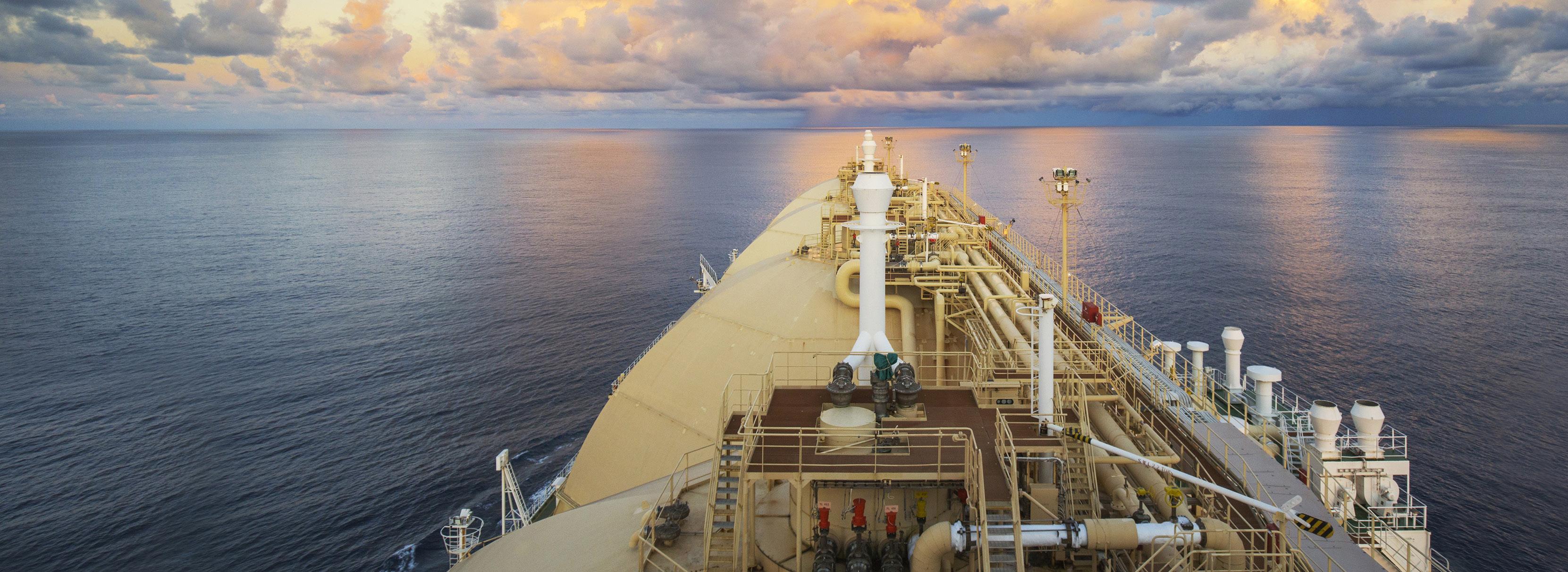
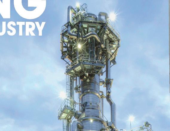
Dr Tobias Eckardt, Dr Margaret Greene, Dr William Dolan, and Justin Pan, (BASF), and Stephen Holmes, Stephen Hughes, and Kevin Cunning (Kinder Morgan), outline how they addressed heavy hydrocarbon freezing while boosting yield at the Elba Island LNG Facility.

Nuno Pedrosa, Behnam Salimi, and Shaun Mohammed, KBC (A Yokogawa Company), describe how advanced technology solutions can propel decarbonisation and operational efficiency within the LNG industry.
John Bell, Akselos, Switzerland, talks about how digital twins can boost efficiency and bolster energy security, in turn helping to revolutionise the European LNG sector.
Will Pernett and Michael Botterbusch, Samson Rope Technologies, USA, asses how digital tools for training and data analysis maximise the efficiency of tug and towage operations.

Alessandro Mari, Paolo Cari, and Sabrina D’Orazio, Saipem, provide insight into the technical challenges and solutions associated with emissions reductions and natural gas contaminants removal for a floating LNG facility.
Frank-Torsten Appel, TGE Marine Gas Engineering, Germany, explains how new configurations and preparing for the future are shaping the market.
Romuald Machac, Hutchinson, South Korea, discusses best practises for LNG tanks.
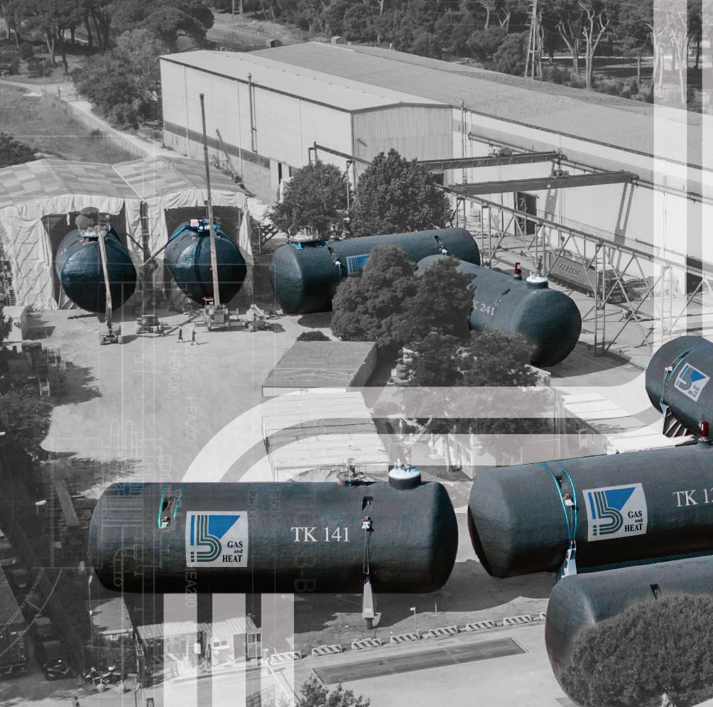
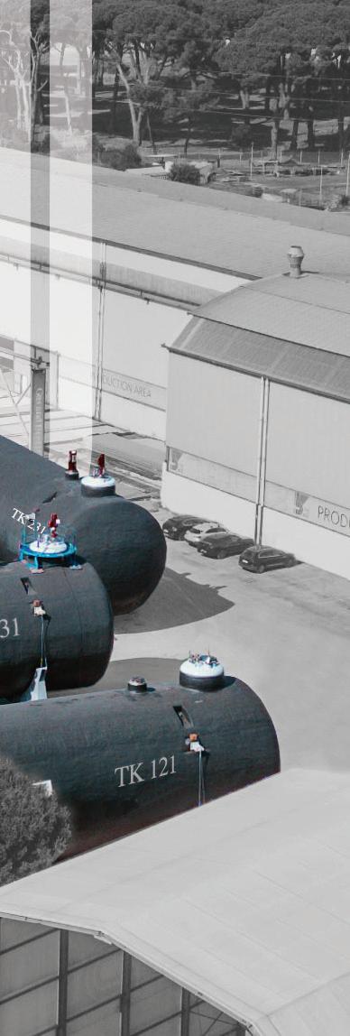
Tank systems for LNG cargo have evolved over time as demands have
The front cover was supplied by STS Marine Solutions and captures one of the company’s recent LNG transfers at the Skaw in Danish territorial waters. STS Marine Solutions is the industry’s go-to independent ship-to-ship company for LNG transfer
With over 18 years of experience around the globe, the company provides the marine inter phase for full scale transfers, gas up and cool down, training, equipment maintenance, project management, and


Wildfires across Southern Europe and the Mediterranean have been dominating the news recently, with thousands of tourists and residents being evacuated and tragic reports of more than 40 deaths in Algeria, Italy, and Greece. 1
There have also been extremely high temperatures in China and Southwestern USA.
Meanwhile, the UK (for the most part) has had fairly mild weathers and periodic rain.
A team of climate scientists – the World Weather Attribution group – said the intense heatwave would have been virtually impossible without human-induced climate change. 1
It is clear that climate change is an ever-increasing problem, and that steps must be made to try and reduce our impact on the world.
One change that could help contribute to this goal is the use of LNG as an alternative fuel. LNG as a marine fuel has become more popular in recent years, due to emitting approximately 25% less carbon dioxide than conventional marine fuels while providing the same amount of propulsion power. 2
While there are obvious downsides, such as its significant methane emissions, the industry is working to find ways to reduce, or maybe even remove, the associated emissions. For example, the European Commission has recently signed a joint statement alongside global partners, which reinforces continued efforts towards the reduction of methane emissions arising across the total value chain of LNG. 3 LNG could prove a viable step in the transition to zero emission fuels.
Another way the industry can reduce their emissions is through the use of bio-LNG. Gasum recently opened a new gas filling station in Sweden, 4
Managing Editor James Little james.little@palladianpublications.com
Senior Editor Elizabeth Corner elizabeth.corner@palladianpublications.com
Deputy Editor Jessica Casey jessica.casey@palladianpublications.com
Editorial Assistant
Théodore Reed-Martin theodore.reedmartin@palladianpublications.com
Sales Director Rod Hardy rod.hardy@palladianpublications.com
as well as recently acquiring a majority ownership in Liquidgas Biofuel Genesis AB, which owns and operates a biogas upgrading plant in Sweden. 5 Gasum intends to investigate the possibility of liquefying the gas on site at some point in the future.
This issue also includes articles touching on this topic, such as that by KBC, which describes how advanced technology can propel decarbonisation and efficiency within the industry.
In addition, Saipem looks at technical challenges and solutions associated with emissions reductions and natural gas contaminants removal for a floating LNG facility. Floating LNG is proving popular in Europe, as the continent tries to move away from its dependence on Russian oil and gas to an independent energy supply, as well as potentially offering a more environmentally-sensitive way to develop natural gas resources.
TGE Marine’s article discusses how LNG shipping can reduce boil-off gas rates, both by reducing the generation and by reusing it as a fuel itself. The industry’s drive to decarbonise is also starting to shape the containment systems on LNG carriers.
You can pick up a copy of the August issue of LNG Industry at Offshore Europe, which will host an Energy Transition Theatre featuring insights and technologies to help the industry transition to a lower carbon economy, and an Energy Transition Zone, located on the exhibition floor, for operators, service, and technology companies preparing the oil and gas sector for a lower-carbon future, and the 24 th World Petroleum Congress, which will have a net-zero approach.
References
References available upon request.
Sales Manager Will Powell will.powell@palladianpublications.com
Production Manager Calli Fabian calli.fabian@palladianpublications.com
Digital Events Manager
Louise Cameron louise.cameron@palladianpublications.com
Digital Events Coordinator Stirling Viljoen stirling.viljoen@palladianpublications.com
Digital Administrator
Leah Jones leah.jones@palladianpublications.com
Digital Content Assistant Merili Jurivete merili.jurivete@palladianpublications.com
Administration Manager Laura White laura.white@palladianpublications.com


The Clean Canaveral LNG bunker barge has completed its first barge-to-ship bunkering of a cargo vessel at Port Canaveral’s South Cargo Berth 4. JAX LNG, along with Polaris New Energy, handled the LNG refuelling of the M/T Damia Desgagnés on the ship’s inaugural call to Port Canaveral.
The asphalt/bitumen tanker, Damia Desgagnés, completed her discharge of cargo and then JAX LNG proceeded with Desgagnés’s first barge-to-ship bunkering of LNG. The seafarers safely transferred approximately 400 m3 of LNG from North America’s largest LNG bunker barge, the Clean Canaveral
The barge-to-ship fuelling operation of a cargo vessel was closely co-ordinated between Port Canaveral, JAX LNG, US Coast Guard Marine Safety Unit Canaveral, and Canaveral Fire Rescue to ensure the LNG bunkering was properly planned, co-ordinated, and conducted safely and efficiently.
The Port Canaveral call marks the first time Petro-Nav deployed the Damia Desgagnés to Port Canaveral and the first occasion the vessel received LNG fuelling by a bunker vessel.
GAC Bunker Fuels, the world’s only bunkering company with integrated ISO 9001, 14001, and 45001 certifications for bunker procurement, which also covers LNG as a marine fuel, traded the LNG transfer and will continue to play a key role in promoting LNG fuelling.
Svitzer, a leading global towage provider and part of A.P. Moller-Maersk, has signed a 15-year agreement to service Gastrade’s Alexandroupolis independent natural gas system (INGS) LNG terminal, the first offshore LNG project in Greece. Svitzer will apply its global terminal towage expertise and experience to rapidly set up towage services and support for advanced LNG operations at the new import terminal. This includes supporting an FSRU with a pipeline system connecting the floating unit to the Greek national natural gas transmission system, and onwards to final consumers in Greece and the Balkans.
Svitzer will provide four new ASD tugboats, fully manned by Greek crew, to assist the FSRU and carriers delivering LNG. Svitzer tugboats will provide berthing, un-berthing, navigation assistance, and other terminal services including firefighting, pollution control, pilot, and boarding party transfer. Svitzer will also provide support and station keeping services to the FSRU during initial installation.
The deal will result in the creation of both onshore and offshore job opportunities based at the terminal in Alexandroupolis. While the Alexandroupolis LNG terminal is set to become operational in the beginning of 2024, Svitzer has already initiated the recruitment process to ensure staff undergo robust training in line with the company’s operational and safety standards ahead of operations commencing. Training will include the use of advanced tug simulators replicating the actual environment around the Alexandroupolis LNG terminal.
Son My LNG Terminal Project Company, a joint venture of AES and PetroVietnam Gas JSC (PV Gas), has been granted the investment policy approval for its Son My LNG Terminal project by Binh Thuan People’s Committee.
The Son My LNG terminal project will be located in Binh Thuan Province, in the South-Central region of Vietnam. The terminal will have an installed capacity of 450 trillion Btu
and is expected to begin commercial operations in 2027.
The Son My LNG terminal project, together with AES’ 2.2 GW Son My 2 combined cycle gas turbine (CCGT), represents a multibillion-dollar investment. Son My 2 CCGT, which received investment policy approval earlier in 2023, will bring safe and reliable energy to power the growth of Vietnam while supporting the transition to cleaner and greener technologies.
Black & Veatch, a company specialising in LNG infrastructure solutions – in collaboration with Samsung Heavy Industries of South Korea – has been awarded a FEED contract for the Ksi Lisims LNG nearshore floating production facility in northwest Canada.
The Ksi Lisims LNG project represents the next generation of LNG export design, re-inventing the industry for environmentally sensitive and greenhouse-gas constrained development situations.

Developed jointly by Western LNG, the Nisga’a Nation and Rockies LNG, the project will be one of the most significant Indigenous-led infrastructure projects in Canadian history. Ksi Lisims (pronounced “s’lisims”) will be hosted by the Nisga’a Nation on their wholly-owned treaty land.
The project will use a floating LNG design that improves the project economics, minimises land impacts, and reduces construction-related risk. With commercial operations anticipated to begin in 2028, Ksi Lisims LNG will be designed to produce up to 12 million tpy of LNG for export to overseas markets.
Eni has delivered a gas cargo of 90 million m3 to the SNAM regasification terminal in Piombino, Italy. Unloading operations took place following the completion of the test phase and mark the beginning of the terminal’s commercial operation.
This additional delivery confirms the value of gas as a reliable energy source, capable of providing a reliable response to growing energy demand while supporting the energy transition.
The cargo was produced at the Sonatrach liquefaction plant in Betihoua, Algeria. The partnership with Sonatrach and Algeria plays a central role in Eni's strategy to diversify supplies and expand its gas portfolio, with investments in fast-track projects that will increase available volumes for the Italian and European markets.
With the arrival of the last module by ship from its fabrication yard in Zhuhai, China, Fluor Corporation has completed the module fabrication programme on the LNG Canada project in Kitimat, British Columbia, Canada. This marks the completion of a critical phase in the construction of a large terminal for the liquefication, storage, and loading of LNG for export to global markets.
Fluor, along with its joint venture partner, JGC Corporation, is delivering multiple aspects of the LNG Canada project, including engineering, procurement, fabrication and delivery of modules, and construction of the project's infrastructure and utilities, marine structures and LNG storage tank.
The first major module, measuring 145 ft tall and weighing more than 5000 t, was received in March 2022. Overall, a total of 215 modules of varying sizes have been received and are being set at the project site. The final module arrived on the morning of 17 July 2023.
LNG Canada is a joint venture between Shell, Petronas, PetroChina, Mitsubishi Corporation, and Korea Gas Corporation. The project will have an initial capacity to produce 14 million tpy of LNG. First shipment of LNG is scheduled for mid-decade.
X GTT to design LNG carrier tanks for Hyundai Samho Heavy Industries
X Reuters: Indian Oil signs long-term LNG import deals
X NNPC and UTM Offshore sign 1.5 million tpy floating LNG project deal
Follow us on LinkedIn to read more about the articles www.linkedin.com/showcase/lngindustry
05 – 08 September 2023
Gastech Singapore www.gastechevent.com
05 – 08 September 2023
SPE Offshore Europe Conference & Exhibition
Aberdeen, Scotland www.offshore-europe.co.uk/en-gb.html
12 September 2023
WEBINAR – Singapore LNG Journey to the Cloud Online
www.lngindustry.com/events/webinar-singapore-lng-journey-to-the-cloud/
25 – 28 September 2023
Turbomachinery and Pump Symposia 2023
Texas, USA https://tps.tamu.edu
02 – 05 October 2023
ADIPEC 2023
Abu Dhabi, UAE www.adipec.com
31 October – 03 November 2023
Americas Energy Summit & Exhibition 2023
Louisiana, USA www.americasenergysummit.com
28 November – 01 December
2023
The 23rd World LNG Summit & Awards
Athens, Greece www.worldlngsummit.com
INPEX CORPORATION has signed a memorandum of understanding (MoU) with PT Pertamina (Persero) on a strategic collaboration to proactively pursue the implementation of the Abadi LNG project in a new partnership following the execution of a sales and purchase agreement between Shell Upstream Overseas Services (I) Limited and Pertamina Hulu Energi (PHE), a subsidiary of Pertamina, and Petronas Masela Sendirian Berhad, a subsidiary of Petronas, concerning the transfer of joint venture partner Shell’s participating interest in the Abadi LNG project to PHE and Petronas. The transfer is subject to the fulfilment of certain joint venture procedures and conditional to the approval of the Indonesian government.
Through its subsidiary, INPEX Masela, Ltd, INPEX is currently preparing the Abadi LNG project for development as operator in the Masela Block in the Arafura Sea in Indonesia.
Through the MoU, INPEX and Pertamina will seek to collaborate strategically on a wide range of fields with a focus on the Abadi LNG project’s value chain. Specifically, the companies will pursue opportunities to collaborate on the offtake and transportation of LNG and other products, the production of hydrogen and ammonia, and the provision of the needs of local stakeholders.
INPEX and Pertamina will also seek to secure the long-term competitiveness and sustainability of the Abadi LNG project, as well as further improvement of project value while generating synergistic effects.
Upon completion of the transfer of Shell’s participating interest to the new partners, INPEX plans to resume project activities, including onsite preparation activities, etc. INPEX recently submitted a revised plan of development (POD) for the Abadi LNG project, incorporating a carbon capture and storage (CCS) component to Indonesian government authorities, and plans to revise the production sharing contract to reflect the incorporation of CCS following approval of the POD. Going forward, INPEX will proceed with preparations required to reach a final investment decision including FEED work, as well as marketing and financing activities, while ensuring it is investable.
The project’s annual LNG production volume is expected to reach 9.5 million tpy, equivalent to more than 10% of Japan’s annual LNG imports.
The Government of the State of Sonora and Mexico Pacific have signed a collaboration agreement supporting Mexico Pacific’s anchor LNG export facility, Saguaro Energía, located in Puerto Libertad, Sonora, Mexico.
Principally, Mexico Pacific’s LNG project was welcomed as the foundational pillar of the Sonora Plan, a clean energy infrastructure and nearshoring initiative announced by the Mexican government earlier this year at the North American Leaders’ Summit held between Mexican President, López Obrador, US President, Joe Biden, and Canadian Prime Minister, Justin Trudeau. The Sonora plan seeks to promote clean energy development, investment, and economic prosperity for the benefit of Sonora and Mexico.
Mexico Pacific’s LNG project, which has the support of Obrador, Sonora Governor, Alfonso Durazo, and other national, state, and municipal leaders, represents the largest foreign private investment in Mexico’s history, bringing employment, infrastructure development and tax revenues to Sonora and Mexico: key objectives of the Sonora plan.

NG is not just a fuel choice; it is a key driver in the global energy transition and decarbonisation efforts. This shift from coal and oil to gas as a cleaner fuel source has sparked interest among producers to expand their production capacity through new construction projects and invest in advanced technologies that enhance their current production capabilities.
As a result, the LNG market is witnessing advancements in various technologies. These technologies can add value in many ways, such as:
� Increasing efficiency in asset management.
� Optimising plant staffing levels.
� Accelerating decision making within the supply chain.
� Enhancing Industrial Automation 2 Industrial Autonomy (IA2IA).

Nuno Pedrosa, Behnam Salimi, and Shaun Mohammed, KBC (A Yokogawa Company), describe how advanced technology solutions can propel decarbonisation and operational efficiency within the LNG industry.
� Increasing energy efficiency.
� Implementing carbon capture storage solutions.
� Optimising production capacity.
This article will explore why reliable modelling software is crucial to achieve these goals.

The LNG market is going through dramatic changes, mainly due to two factors: the decarbonisation targets set by numerous countries, and the geopolitical situation which requires many countries to adapt and find new domestic or international sources of LNG.
According to the Global LNG Outlook 2023 – 2027 report from the Institute for Energy Economics and Financial Analysis (IEEFA),1 a wave of new LNG projects is scheduled from 2025 – 2027. However, the report also signals the potential challenge of weaker-than-expected demand, which could lead to lower prices and profits for LNG suppliers and traders.
On a more positive note, the report also indicates a significant increase in European LNG demand over the past few years. Between 2019 and 2021, Europe relied on imported LNG to meet around 20% of its gas demand. However, in 2022, the proportion
of LNG in total gas demand increased significantly, surpassing the 35% mark per the report.
Given these market dynamics, it is even more crucial to have highly optimised processes to maximise the benefits from the existing production capacity. Optimised processes can help LNG producers extract the most value from their operations, improve efficiency, cut costs, and stay competitive in a potentially challenging market.
By implementing advanced technologies, streamlining operations, and enhancing overall productivity, LNG suppliers
can position themselves favourably to navigate market uncertainties and leverage the growing European demand.
The main purpose of LNG is to have a more efficient way to transport natural gas. It is cheaper to transport liquids than to transport gas, as the transported volume is much smaller for the same amount of gas. Natural gas comes from many kinds of reservoirs, and there are two main types: conventional gas, either from gas fields or gas associated with oil fields, and non-conventional gas, such as tight gas from fracturing, naturally occurring hydrates, and more.
To liquefy natural gas, various commercially-available production packages exist. They are fundamentally based on the same principle: a series of cooling and compressing cycles. The packages primarily differ based on the choice of coolant, number of cycles required, and the inclusion of precooling steps.
As described in the previous section, producing LNG, and consequently, its transportation and storage require equipment that can withstand the low temperatures of -161˚C. To minimise CAPEX, it is essential to model fluids and processes accurately and avoid over or under-dimensioning materials.
Traditional process simulation for most of the applications employs cubic equations of state (EoS). These are models that are improvements over the original cubic EoS developed by Van der Waals in the late 19th century,2 and its principles, with some modifications, are still widely used for general purpose hydrocarbon production and processing.
However, it has important limitations that even the latest modifications have not improved. The main limitation is the low accuracy to predict volume of liquids, and even their compressibility, i.e., how much the volume changes with applied pressure.
LNG process licensors know this, and over the years many have developed their internal multi-parameter models that are maintained by only a few people inside these companies. Operating in this manner carries inherent risks, particularly when the knowledge surrounding these models is lost or inadequately maintained. As time progresses, it becomes increasingly challenging to ensure that the models remain current with the latest developments.
In recent years, the concerted efforts of many research groups worldwide have been instrumental in reversing this trend. Their work has focused on developing general-purpose models that strive for the highest possible accuracy in predicting key properties that can be measured. These properties typically include volume (density), compressibility, heat capacity, as well as bubble and dew point temperatures and pressures. The main groups dedicated to this initiative are the U.S. National Institute of Standards (NIST) and the European Gas Research Group (GERG). The latter using previous works of various researchers, grouped and improved several EoS known as the GERG-2008 Equation of State (EoS). This EoS is now an ISO standard (ISO 20765-2/3) for natural gas.
The GERG-2008 EoS, while having some limitations in its scope, still shows a satisfactory level of generality when applied to LNG processes. However, challenges arise when
dealing with LNG mixtures containing heavier components. In response, a dedicated group of researchers recognised the need for an improved approach and re-parameterised the fundamental equations derived from GERG-2008, specifically tailored to the components of interest in LNG. This re-parameterisation led to the development of a specialised EoS known as EOS-LNG. In this work, the focus was on the following sets of binary mixtures: methane and n-butane, methane and isobutane, methane and n-pentane, and methane and isopentane.
These equations are significantly more complex than the traditional cubic EoS, but with the improvements in computational power, they become usable for these applications and can be used directly in process simulators. The relatively low number of components also helps to make calculations more efficient.
For many years, KBC’s Multiflash® technology has included high accuracy models as part of the thermodynamics package, even before GERG-2008 was published. The most current versions have GERG-2008 as well as the purpose-built model for LNG, the EOS-LNG equation. This work shows the improvements in these models compared to each other and in relation to popular versions of cubic EoS: Peng-Robinson (PR). For density predictions with cubic EoS, many attempts have been made to improve it. One of them includes performing a volume shift on the equations as proposed by Peneloux. This version of PR EoS is also considered in the study when comparing density predictions.
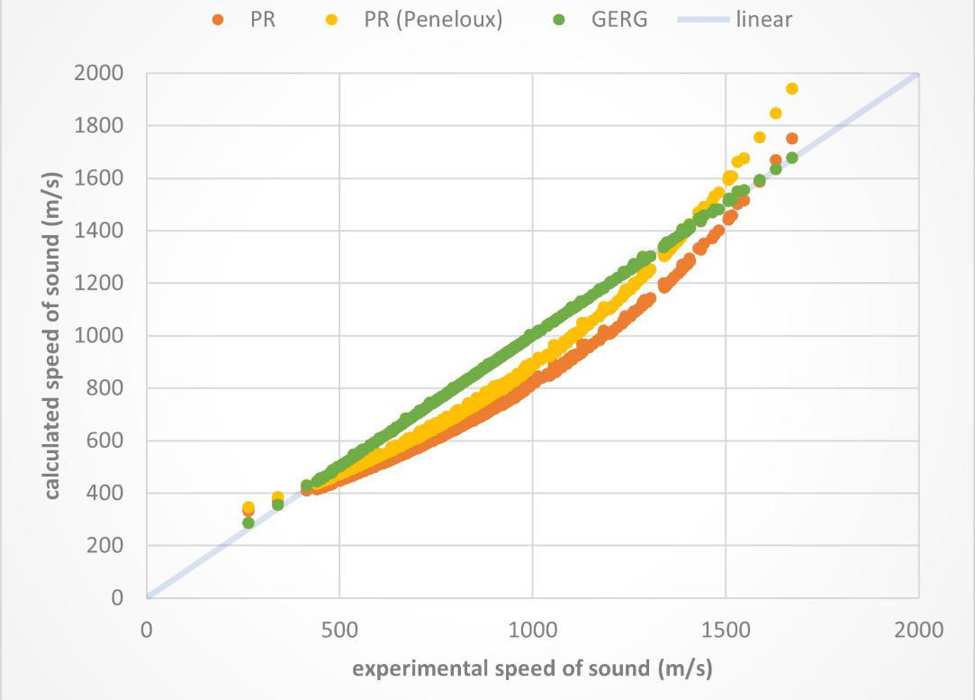
The performance of three models, namely PR, GERG-2008, and EOS-LNG, have been evaluated for a specific set of components. These models have been assessed based on important properties such as density, Joule-Thomson coefficient, compressibility, heat capacity, and the speed of sound, which is particularly relevant for transportation purposes. Knowledge of these thermophysical properties is very important for precise design and optimising transportation. Although different experimental techniques are available to measure thermophysical properties of fluids, direct measurement at high pressure is difficult for some properties, like the Joule-Thomson coefficient. Therefore, it is preferred to use indirect methods to determine these properties employing other measured properties. The speed of sound in fluids is one of the most useful thermodynamic properties that can be used to determine other thermodynamic properties like density, isobaric heat capacity and Joule-Thompson coefficient. Moreover, in comparison with other thermodynamic properties, the speed of sound can be measured with high accuracy in the laboratory, which makes it very special.
The systems that will be covered are pure methane. After all, LNG is composed mostly of methane, and a simple mixture that covers the typical LNG composition.
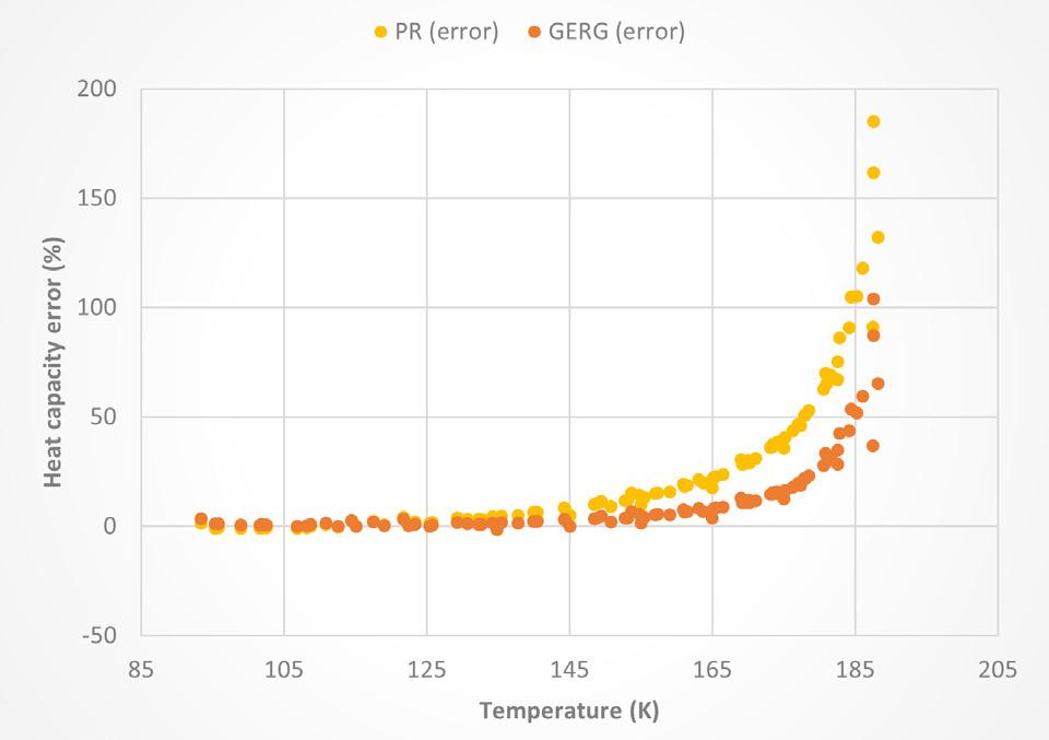
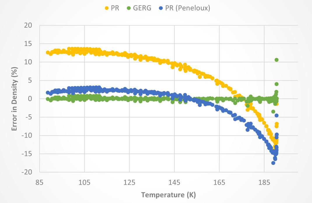
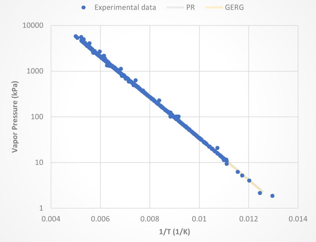
However, a preliminary assessment of the models’ performance against available experimental data is necessary before proceeding. Methane is the most important component to consider when doing calculations for LNG applications. The plots depicted in Figures 1 through 4 show how the models, PR and GERG, perform when predicting methane properties. For pure components such as methane, GERG, and EOS-LNG perform the same. However, the parametrisation of mixtures distinguishes GERG from EOS-LNG as shown in Figures 5 – 9.
Looking at the results shown in Figures 1 – 4, both models perform relatively well for vapour pressure and heat capacity. The GERG type model is slightly better in predicting heat capacity.
However, the density and speed of sound are not very well predicted. This is a known limitation of the cubic EoS models. They still fall short from experimental data, even when using extra terms to improve density predictions. As seen in Figure 2, it is impossible to get an error below 15%, on average.
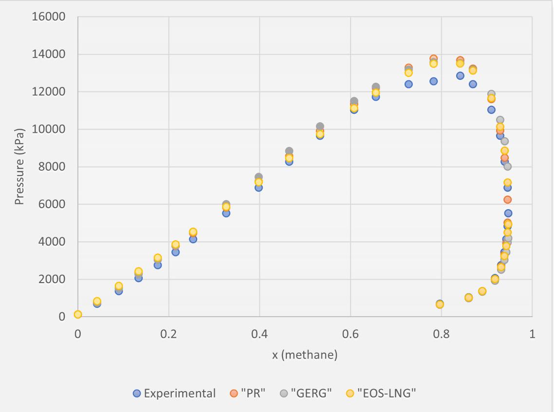
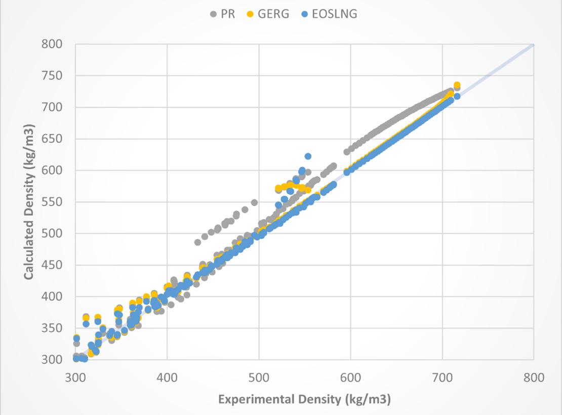
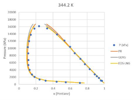
For the system methane/butane, as far as vapour equilibria is concerned, all models perform quite well, as shown in Figure 5. For density, the cubic EoS models show the same limitation as in the pure component case. In Figure 6, they are shown to be much less accurate than GERG or EOS-LNG. As demonstrated in Figure 7, for heat capacity of the methane/butane mixture, EOS-LNG model shows better agreement with experimental data compared to the other models.
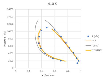
Another example where EOS-LNG shows a big improvement to LNG processes is the methane/pentane mixture. As shown in Figure 8, at higher temperatures, EOS-LNG
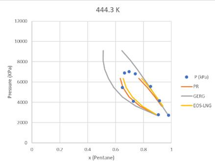
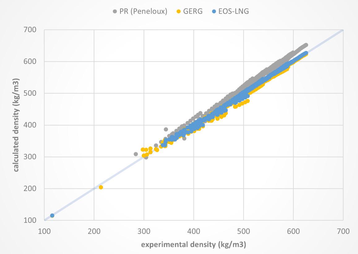
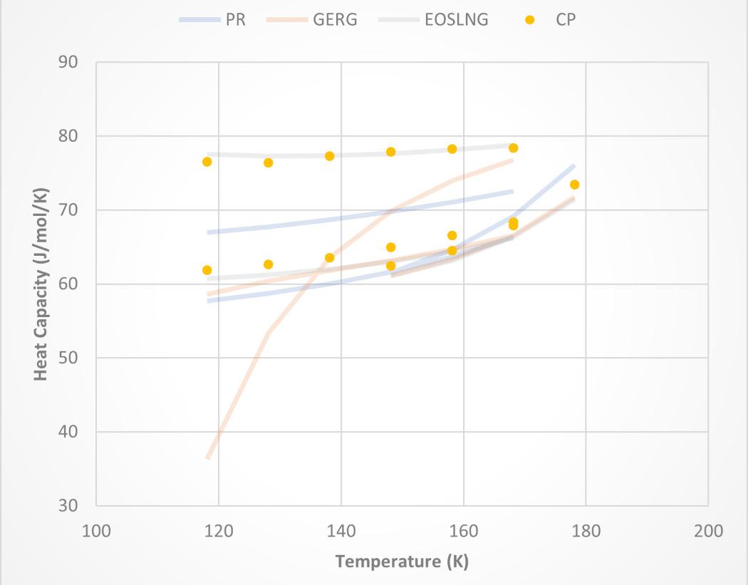
can reproduce the data better than GERG. Interestingly, PR performs quite well, but as Figure 9 depicts, the density predictions by PR are worse than GERG or EOS-LNG models, particularly for higher densities, where LNG is of interest.
Processing natural gas for LNG has been a long-standing practice, but the accuracy and applicability of models have historically lagged. However, thanks to the rapid advancements in computer technology, more precise models can be made readily available to a broader audience. By incorporating these advanced models into the process-solving approach, the reliability of the results can be significantly improved.
Integrating accurate models into process simulation enhances equipment sizing to perfectly match the requirements without unnecessary oversizing or undersizing. This optimisation can lead to cost savings, increased efficiency, and improved overall performance.
Moreover, reliable models aid in assessing the correct values of utilities employed in the process. By accurately estimating the required utilities, such as energy inputs or cooling water, operators can optimise resource utilisation and enhance the overall sustainability of LNG production while minimising waste.
With wider accessibility of more accurate models, users can make informed decisions based on reliable predictions. This not only improves the overall operational efficiency but also reduces uncertainties and risks associated with process design and optimisation.
In summary, advanced modelling tools enable more accurate predictions and wider applicability in LNG processing. By leveraging these models, operators can ensure proper equipment sizing, optimise resource utilisation, and make informed decisions to enhance the reliability and efficiency of the LNG production process.
1. ALAM., S., et al., ‘Global LNG Outlook 2023-27’, Institute for Energy Economics and Financial Analysis, (15 February 2023).
2. VAN DER WAALS, J., D., On the Continuity of the Gaseous and Liquid States, Leiden, (1873).
3. KUNZ, O., and WAGNER, W., ‘The GERG-2008 Wide-Range Equation of State for Natural Gases and Other Mixtures: An Expansion of GERG-2004’, Journal of Chemical & Engineering Data, Vol.57, No.11, (2012), pp.3032 – 3091.
4. THOL, M., RICHTER, M., MAY, E., LEMMON, E., and SPAN, R., ‘EOS-LNG: A Fundamental Equation of State for the Calculation of Thermodynamic Properties of Liquefied Natural Gases’, Journal of Physical and Chemical Reference Data 48, 033102.
The world is currently in the midst of a boom for LNG. Since Russia invaded Ukraine in early-2022 and weaponised natural gas exports, Europe has turned to LNG to plug the gap, causing the industry to explode, particularly in the US. This growth is set to continue, with Europe expected to hit record LNG exports in 20231 and approximately 25 new terminals planned for the near future. 2
However, despite recent successes, the industry still faces several significant challenges. In Europe, import infrastructure is insufficient to deliver enough LNG, as import capacity is only enough to meet approximately 40% of the total gas demand. 3 As a result, operators are running ageing terminals at full capacity to maximise production, increasing the risk of issues arising and causing costly unplanned downtime. Moreover, while LNG is more environmentally-friendly than coal and oil, the EU aims to be climate neutral by 2050. Therefore, it is undertaking a delicate balancing act by increasing LNG import capacity to meet short-term needs, while being careful not to undermine its transition to net-zero emissions by 2050. There are also challenges when shifting the focus outside of Europe. The war in Ukraine and the subsequent European push to replace Russian gas with LNG drove down prices to record levels in 2022, pricing out many
Asian nations, some of whom faced gas and power shortages, defaulted on long-term contracts, and were forced into expensive spot markets. Therefore, while the future of the industry is bright, there are undoubtedly challenges that must be overcome to ensure long-term success.

How can the LNG industry capitalise on the sudden increase in demand while addressing the difficulties? The answer, it can be argued, is digital twins.
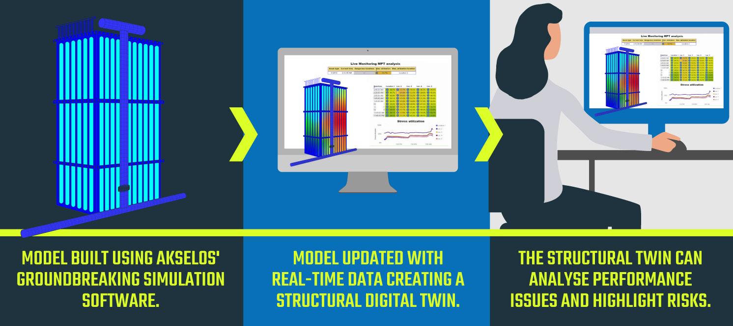
A digital twin is a virtual representation of a physical asset or process which mirrors its real-world counterpart in real time. To create a digital twin, engineers first build a detailed model and then pair it with data, including (historic) inspection and sensor data. As new information is fed into the digital twin, the asset owner gets detailed insights into risk areas to optimise maintenance and inspection and prevent failures.
The technology can also help engineers improve operational efficiency to achieve more output. Through near real-time updates of the digital twin with process data, the asset owner always has the view of the asset ‘as it is today’ and can undertake predictive maintenance that maximises asset life.
John Bell, Akselos, Switzerland, talks about how digital twins can boost efficiency and bolster energy security, in turn helping to revolutionise the European LNG sector.
Digital twin technology has already been successfully deployed on critical European LNG infrastructure to improve operations and increase asset lifespan. In Italy, Akselos is currently partnering with Adriatic LNG to use its digital twin technology to enhance the operations of the Adriatic LNG regasification terminal – an offshore gravity-based structure. The terminal offers a comprehensive regasification service, including the berthing of LNG carriers, LNG unloading and storage, regasification, and finally, the delivery of natural gas to the gas pipeline network. It has a regasification capacity of 8 billion m 3/y of LNG and is vital for Italy’s energy mix – supplying over 10% of the national natural gas consumption. 4
Inside the Adriatic LNG terminal are four open rack vaporisers (ORVs), one of the most critical components of a regasification terminal. ORVs use seawater flowing on the surface panels of numerous heat exchanger tubes to vaporise LNG to be regasified.
A common issue with ORVs is their pipes becoming overstressed due to the difference in temperature between LNG, natural gas, and seawater. Such pipe stress is significant as, if left untreated, it can worsen, causing unplanned downtime or even a full scale breakdown of the ORV.
Up to this point, operators have had no visibility into which pipes were stressed due to limited asset integrity management tools, which cannot give an accurate picture of asset health. This is because legacy tools are based on finite element analysis (FEA) – simulation software that allows engineers to simulate a system’s stress, deformation, and other physical properties without requiring expensive and time-consuming physical testing.
While FEA is a powerful tool, it cannot analyse large and complex systems with great accuracy. Therefore, when using FEA-based asset integrity management tools, regasification terminal operators know that ORV pipes will likely bend and need repair but cannot identify them in advance and proactively prevent damage and subsequent asset downtime.
To overcome the challenge, Akselos has developed digital twins that are powered by a new simulation technology called reduced basis finite element analysis (RB-FEA).4 This can provide a holistic view of the entire asset with unparalleled speed and accuracy. When used to create digital twins, RB-FEA allows operators to pinpoint critical safety issues down to the millimetre level and proactively fix problems before they escalate. Adriatic LNG chose to work with Akselos as the model of the ORV would have been too large to compute with traditional FEA-based simulation software. They were confident that Akselos could build a large model and, subsequently, a digital twin, as the company had previously modelled the Shell Bonga FPSO unit – the world’s largest asset protected by a digital twin.5
In the project’s first phase, Akselos used its RB-FEA software to build a detailed model of one of the ORVs, using input data from drawings, inspection data, and load history (including pressure and temperature).
Next, Akselos undertook a fitness for service (FFS) assessment of the ORV on the digital twin, including elastic and plastic analysis, which was validated by Bureau Veritas. While the ORV passed the FFS assessment, operators discovered that certain pipes were under more stress than others and would need maintenance much sooner. Akselos displayed the results on an easy-to-digest dashboard, allowing operators to rank the tubes based on their fatigue life.
With the Akselos digital twin, Adriatic LNG operators can undertake
continuous FFS assessments instead of the typically large intervals between each assessment. Moreover, the operator now has an insight into each ORV tube down to the millimetre level and can undertake predictive maintenance to catch issues before they arise, avoiding asset downtime and securing the flow of natural gas to the mainland.
The next step in Akselos’ partnership with Adriatic LNG is to build digital twins of the three other ORVs on the regasification terminal and complete FFS assessments for each. This will give operators a holistic view of the health of all four of the terminal’s critical ORVs.
Further afield, there is enormous potential to use digital twin technology to enhance the performance and efficiency of the LNG sector in Europe – and the world. Firstly, the majority of LNG terminals contain ORVs which can be analysed in the same way as Adriatic LNG’s ORV. Building digital twins and undertaking assessments of all these ORVs would further allow operators to identify issues before they worsen, improving performance and extending asset lifespan.
Secondly, additional opportunities exist in the border LNG value chain to utilise digital twin technology. Virtually all LNG import terminals have additional components prone to stress issues, including piping and loading arms. Digital twins could also improve the operational efficiency of LNG export terminals and tankers in the same way.
Overall, using digital twins in the European LNG industry would help improve operations and increase the lifespan of critical, aging assets, increasing the flow of natural gas to a continent desperately in need. Moreover, the technology would allow European operators to get more out of their assets, thus reducing the need to build as many new terminals as possible, risk locking in future emissions, compromising its long-term climate neutral ambitions. Finally, digital twins can potentially bring enormous benefits outside of Europe. In Asia, where nations have been priced out of an ever more expensive market, the technology can help operators regasify as much of the LNG purchased as possible while avoiding costly downtime.
The world’s future is digital: for the LNG industry, that future is already here with digital twins.
1. ‘Europe to hit record LNG imports in 2023 – analyst’, Montel, (7 March 2023), www.montelnews.com/ news/1452423/europe-to-hit-record-lng-imports-in-2023-analyst
2. ELLIOTT, S., ‘Feature: Europe’s dash for new LNG import infrastructure picks up pace’, S&P Global, (10 August 2022), www.spglobal.com/commodityinsights/en/market-insights/ latest-news/natural-gas/081022-feature-europes-dash-fornew-lng-import-infrastructure-picks-up-pace
3. ‘Infographic – Liquefied natural gas infrastructure in the EU’, European Council – Council of the European Union, (20 December 2022), www.consilium.europa.eu/en/ infographics/lng-infrastructure-in-the-eu/
4. ‘The Terminal’, Adriatic LNG, www.adriaticlng.it/en/theterminal
5. ‘World’s Largest Structural Digital Twin: Akselos’ successful deployment for Shell’s Bonga Main FPSO’, Akselos, https://akselos.com/worlds-largest-structural-digital-twinakselos-successful-deployment-for-shells-bonga-main-fpso/
-196℃ to +120℃
We manufacture floating and trunnion-mounted ball valves specifically designed for process applications operating at temperatures below -50℃, down to -196℃
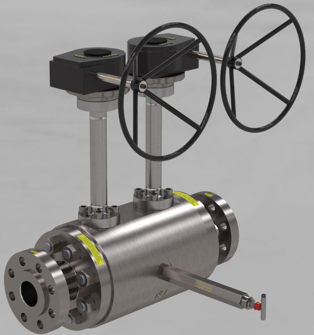
Our soft seated design includes specially selected materials of construction to ensure full compatibility with low temperature requirements.
• 1” to 20” Bore Size - DN25 To DN500
• Single Isolate, DIB or DBB Designs
• DVT Qualification Tested to Shell Standard 77/300 & 77/312

• Fugitive Emission Tested to 77/312 Class BH
• Pressure Equipment Directive 2014/68/EU


• ASME Class 150 - 900


nergy imports and exports are significant components of the global economy. With a worldwide fleet of nearly 700 vessels and another 200 newbuilds on order, LNG shipping on maritime routes relies on the safety and security of high-performance synthetic ropes. That reliance grows every year. Workboats assisting with berthing, getting underway, and escorting vessels depend on stronger, lighter, and longer-lasting synthetic fibre ropes than the technology they replaced. Mooring ropes, deployed when in port, and ropes used for long-term mooring of FSRU vessels, have transitioned from the steel wire ropes, commonly used three decades ago, to today’s high-performance, high-modulus synthetic ropes. In all cases, the result has been increased crew safety and faster, more efficient operations. Like any other onboard asset, maintaining those benefits requires attention to the working environment – equipment condition and proper handling by crews trained in best practices supported by data and asset management across the fleet. Today, digital tools have been developed that bring a new level of information access and analysis to maximising these benefits across fleets.
Historically, manufacturers have developed products with the latest technology to maximise the potential for high strength and a long working-life. Samson is a rope manufacturer that pioneered the first high-performance, high-modulus mooring lines in the 1980s. These lines proved to be faster to deploy, required fewer crew to handle, and resulted in significantly reduced handling injuries than the steel wire mooring lines commonly used at the time. The tug-and-vessel assist industry has relied on the new generation of high-performance synthetic ropes for the same benefits – more efficient, faster operations, greatly reduced risk, and longer service life. Both rely on a systems approach to thinking about the vessel’s needs. Mooring systems consist of: the equipment and hardware, the mooring line, the sacrificial pendant, and the chafe gear that allow the system to handle the stresses of daily operations. Towing systems also benefit from a similar systems approach – in addition to well-maintained hardware and equipment, backer lines, mainlines, and sacrificial pendants that also absorb the stresses of day-to-day handling, all of which are protected from abrasion with chafe gear.
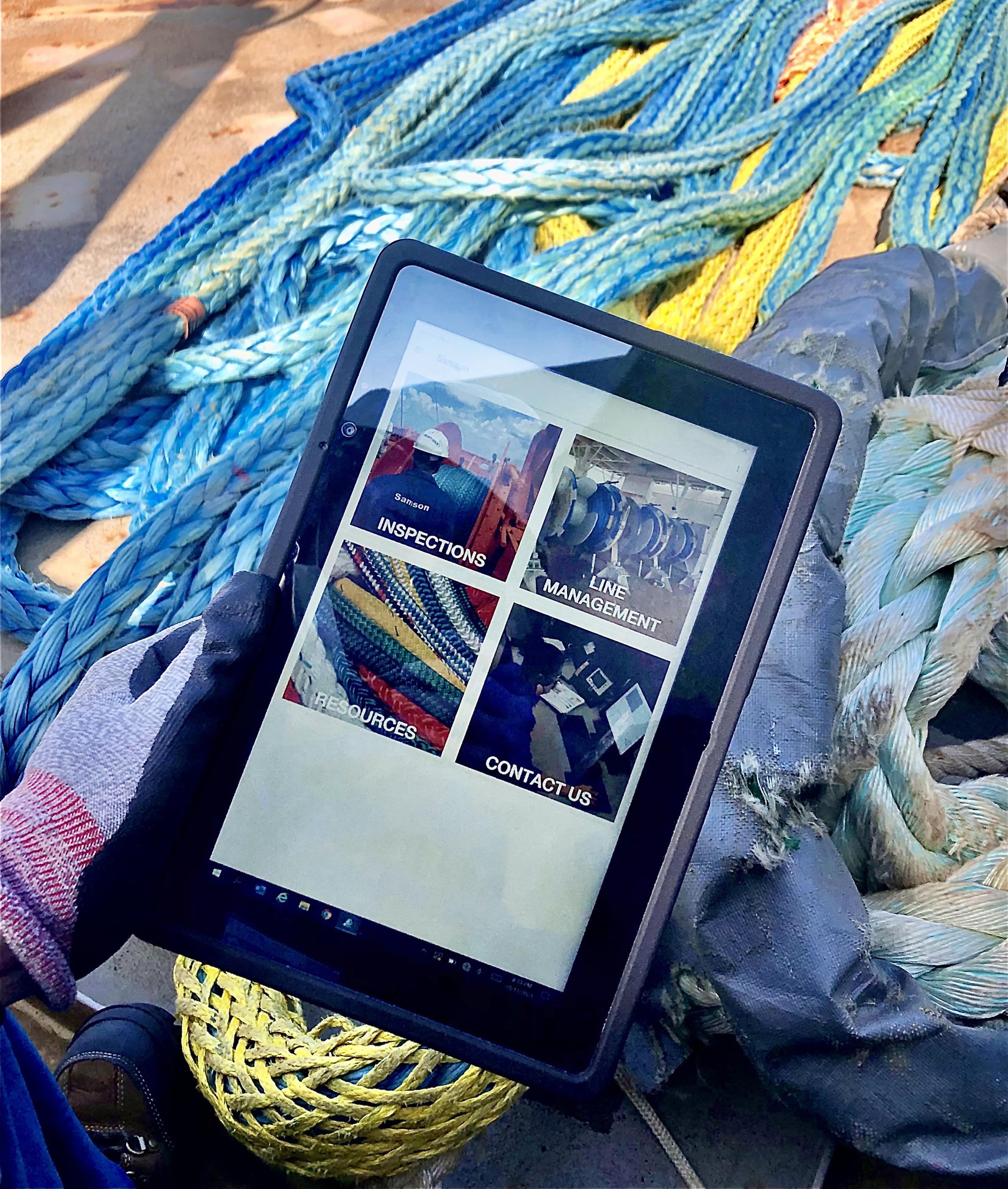
It is essential that crews deploying these systems know the requirements for proper handling and best practices in maintaining these valuable assets, in order to maximise efficiency on each vessel. In both cases, educating the crews responsible for the deployment, handling, rigging, and inspecting the ropes is critical. With this holistic approach in mind, the company has taken the initiative to develop comprehensive online digital training modules, asset management and tracking systems, and a cross-platform application, to simplify field

Will Pernett and Michael Botterbusch, Samson Rope Technologies, USA, assess how digital tools for training and data analysis maximise the efficiency of tug and towage operations.
inspection of working ropes and to facilitate consistent logging of critical data.
Generally, crew members receive in-person onboarding and annual training through their employers. Methodology and consistency can vary between trainers and organisations. Best practice recommendations for inspection techniques, installation procedures, and repair processes may differ among trainers or be entirely unknown in some areas. Online resources provide a classroom-like experience for crew members and standardise training across the industry. Internet access is readily available around the globe.
The rope system is a valuable asset aboard the vessel. Online digital training provides consistent guidance from industry experts for best practises. Synthetic fibre is designed to last for thousands of operations, but misuse due to poor training can cut the line’s life short at any point. A digital training platform,
that tracks course completions and training renewals, streamlines the learning process while providing documentation.
Digital training is a huge step forward for the maritime industry. The online teaching environment brings end users the latest information straight from the product manufacturer. Samson has issued over 2500 course completion certificates to end users enrolled in our online CLASSROOMTM, and recently launched a series of courses designed specifically for the towing market. This platform allows for direct contact with customers on a scale that is not possible with in-person learning sessions. In addition, digital training enhances crew safety and efficiency when working with synthetic rope. An example of this is training on correct rope-handling procedures. Proper rope installation onto a winch, and inspection and verification of hardware surfaces that the rope interacts with prevents damage to the line. The benefits are two-fold: increased crew safety, and protection of the critical asset that is the towing system.
Synthetic rope is integral to the maritime industry, and it is important to understand how it performs by viewing the operational system holistically. Digital advancements have allowed rope users and decision-makers to use an online portal system to manage their lines’ condition, usage, and policies. Crucial statistics on inspection details, fleet analysis, and general data management allow field personnel and staff to observe trends in line life. In addition, the realm of data gathering is expanding. New metrics, such as tension monitoring, are being explored to better understand rope performance. Once captured and made available, these trends help determine optimal timing for line inspections, planned replacements, or documenting anomalies in performance.
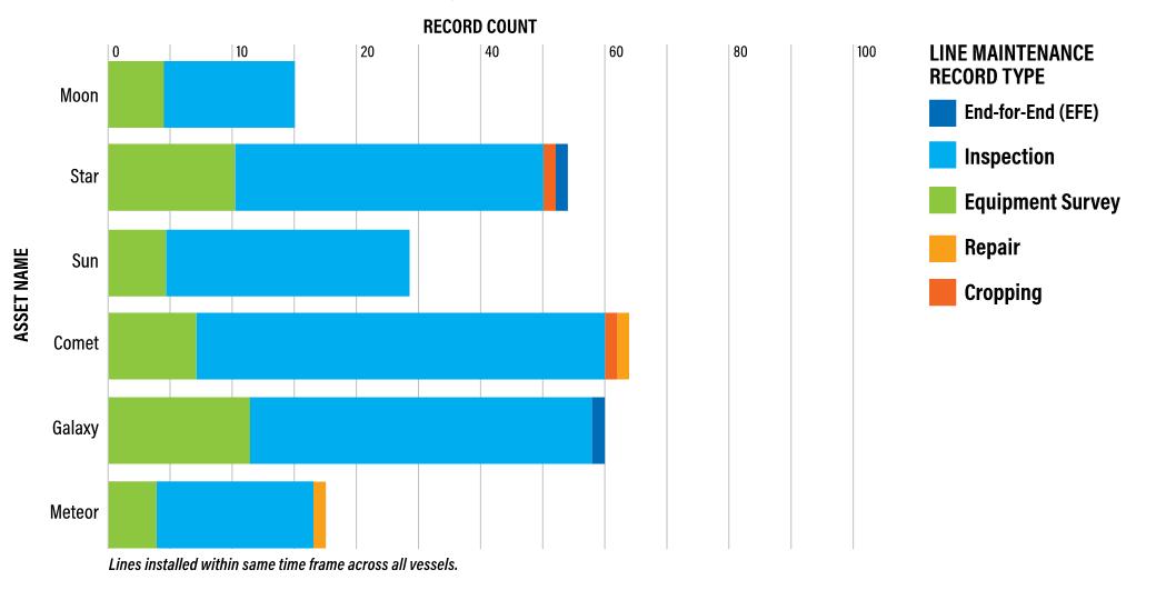
By documenting these line life indicators, vessel safety is improved. Damage is proactively identified, and lines are retired before they fail. The digital dashboard allows operators to view, compare, and manage vessels and associated lines at the fleet level. It enables active rope management to ensure that lines are being used efficiently while keeping the vessel in a safe operating range. An example of how the asset management team can easily spot discrepancies in maintenance operations is seen in Figure 2. In this scenario, the Moon and Meteor vessels need to perform inspections more frequently. The other workboats have had lines installed for the same amount of time but conduct a higher number of inspections. Increased visibility allows proactive action to take place well before any issues arise. Digital asset management for rope products is a powerful tool, and it continues to progress to help end users understand line performance.
Traditionally, line usage has been tracked using paper systems or simple data logging. While these entry methods allowed for a quick record of line status, an in-depth analysis of line performance and lifespan was difficult. As technology has progressed, nearly all documentation has shifted to advanced
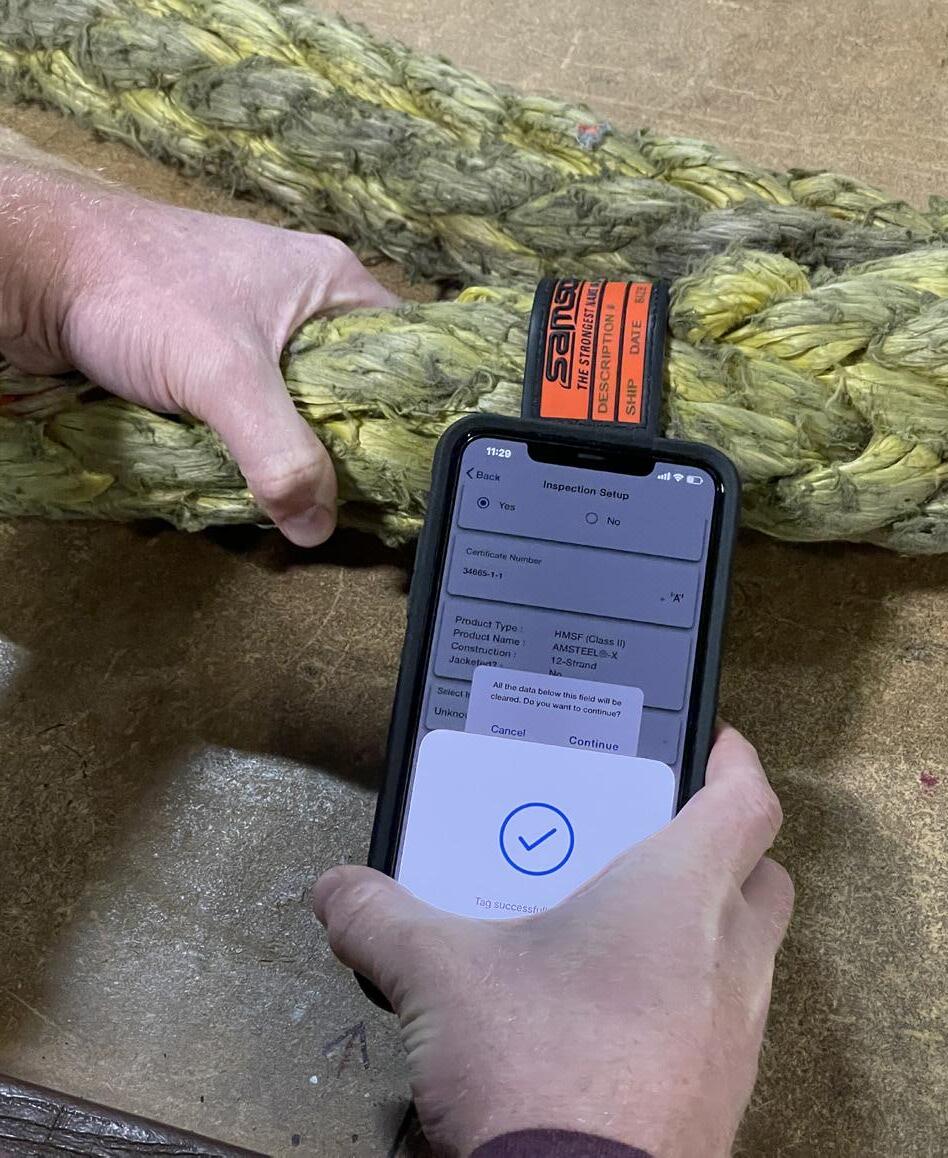
The Samson App takes the guesswork out of what to inspect and pinpoints the exact position and severity of damage. Make informed decisions based on your inspection results with the Samson App.
The ICARIA® Service Program, including the Samson App, CONNECT ™ , and CLASSROOM™ , assists with rope condition and usage monitoring, enabling early damage identification, incident prevention, and life optimization.


Redefine your rope management system today!
SamsonRope.com/Services/Icaria

digital systems. Digital systems allow crews to perform a rope inspection using a mobile device. Samson provides an application to guide users in performing a complete inspection, from capturing images of the rope, to uploading metrics, such as port locations, significant weather events, and shock-loading situations to the database. Using the app, inspections are standardised between operators and vessels, with the data housed within a single system. Mobile notifications create an easy reminder when an inspection needs to be performed.
When reviewing rope degradation, data-supported insights add value to assessing the wear level on a rope product. The growing prevalence of RFID-enabled tagging on equipment, allows for direct synchronisation with a mobile device. A quick scan lets the operator view all pertinent line information within the application and begin an inspection immediately.
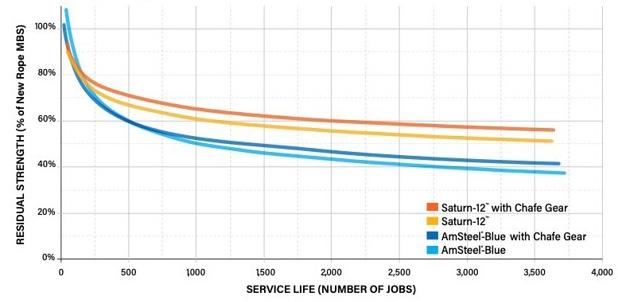
When populated with data and maintained regularly, digital asset management allows analysis and further learning regarding rope behaviour. The database can be utilised to determine the performance of one towline compared to another. For example, Samson’s AmSteel Blue® and Saturn-12TM could be used separately as mainlines and usage tracked in a digital system. Various metrics such as load, hours in use, total operations, and type of tow operation are recorded. The wear rate on each line is captured through periodic inspections, which get input into the digital asset. With enough data, the two ropes can be compared (Figure 3).
In this scenario, 35 AmSteel Blue and Saturn-12 pendants were installed across 11 tractor tugs and put into service for over
27 000 operations. Performance was tracked consistently. Some pendants had chafe installed, while others did not. After experiencing real world working conditions, the lines were tested to destruction to assess residual strength. The data collected revealed that the wear rate on Saturn-12 was significantly less than AmSteel-Blue over the same operational period. A metric was yielded for chafe extending the lifetime of both ropes by protecting the load-bearing line. Data analysis capabilities give direction in selecting a synthetic rope product and chafe for various tug operations.
Digital rope tracking allows operators to measure the cost per tow for any synthetic product. With detailed monitoring of the rope’s lifetime through line usage reported, the upfront cost is broken down into the total number of operations before the rope reaches retirement.
The end goal is to monitor the life of the line and make data available to assist with deciding when to either retire a line or extend that line’s life past the retirement date. It defines the cost efficiency within a risk model. This helps end users determine the correct product based on the expected number of operations and the nature of the task. A high-cost rope may not be appropriate for a small number of operations before it is retired. However, the investment is validated when the number of tows is recorded along with other factors such as the severity of loading, chafe gear present, and other critical metrics.
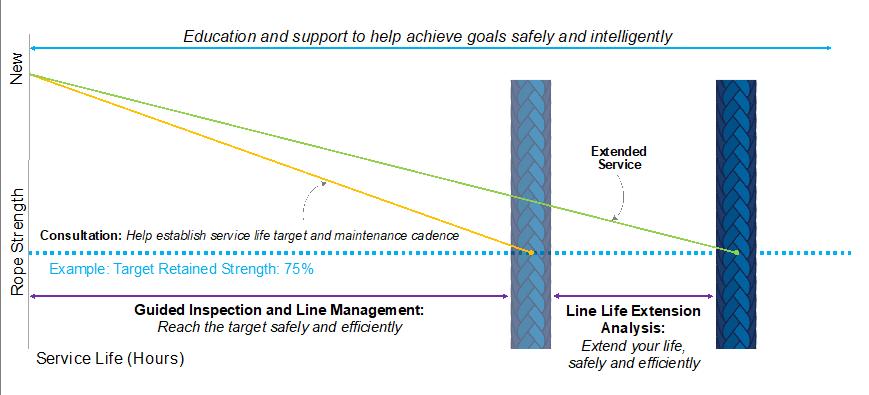
Line inspections, usage documentation, damage and repair data, and residual strength testing are all resources that contribute to a company’s line management plan to get the most usage from lines that otherwise would have been retired solely on policy or line age. For example, in Figure 4, a company can set initial life expectations based on historical data and experience. Then, with supporting data, a company can extend the line usage safely beyond the retirement policies initially set.
Equally of value is identifying damage or high wear, so lines can safely be retired before an incident occurs. Data gathering can be used in the tug and towing industry to identify line life extension, reduce the cost per tow by using digital inspection tools, and for destructive and nondestructive line evaluation.
Digital training gives the crew a better understanding of rope-handling techniques and inspections. The personnel aboard a vessel are well-equipped to handle synthetic rope safely and effectively in daily operations.
Digital asset management allows analysis on a broad scale, giving operators a view of rope performance across an entire fleet and identifying trends. The virtual dashboard of data maintains a high level of safety while ensuring that ropes are being used to their fullest potential.
Mobile applications and RFID tagging bring ease of inspection and usage tracking. Consistent tracking of data allows the cost per tow to be realised and streamlines the decision process of extending line life to continue to offset the upfront cost of rope.
The natural gas industry is a pillar of the energy transition and, as such, is strongly focused on reducing emissions in its value chain. Besides carbon footprint reduction, the release of other contaminants removed in the natural gas treatment into the environment is also a point of attention.

Among these contaminants, sulfur species and the consequent sulfur dioxide (SO 2) emissions are a typical concern. If compared to the past, more stringent limits are imposed to the SO 2 content in the flue gases released to the environment; in many countries, the emissions limit has been reduced from the previous value of 800 ppm vol. down to 50 ppm vol.
For this reason, the installation of standalone thermal incinerators to manage the acid gas streams from acid gas removal unit (AGRU) is no longer a final solution since the resulting SO2 content in the flue gas would be likely to exceed the tighter limit, even in presence of a low hydrogen sulfide (H2S) content in the natural gas to be treated. This topic should be carefully considered and properly addressed at early project stages, both during the process configuration assessment and technologies screening.
Using a case study based on the experience gained during the FEED development of a floating LNG (FLNG)
Alessandro Mari, Paolo Cari, and Sabrina D’Orazio, Saipem, provide insight into the technical challenges and solutions associated with emissions reductions and natural gas contaminants removal for a floating LNG facility.
and onshore gas treatment facility, this article aims to present the possible modifications and/or integrations to the original acid gas streams management scheme, comparing three alternatives from different perspectives:
Since it has been demonstrated to be responsible for a multitude of respiratory diseases and environmental issues (i.e. acid rains), SO 2 has gradually emerged as one of the major targets of governments attempting to improve the ambient air quality.
Initial attempts to reduce SO 2 emissions mainly focused on the power industry as the largest emitter, especially from coal-based power plants. As the power plants in Europe and in the US have progressively shifted from coal to natural gas, the focus of regulatory agencies on pollutants, such as sulfur compounds, was adapted as well.
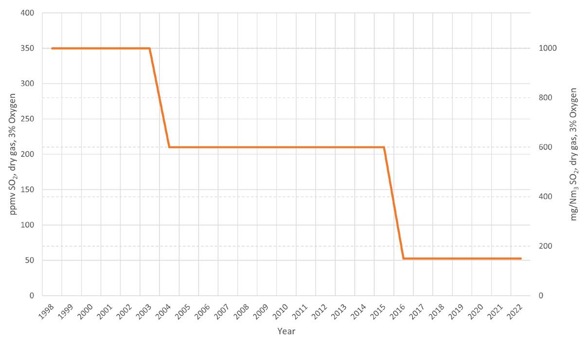
If compared to the past, more stringent limits are nowadays imposed to the SO 2 content in the flue gases released to the atmosphere, thus requiring deeper fuels conditioning for cleaner combustion; as a representative example, many countries have lowered the emissions limit from 800 ppm vol. to 50 ppm vol. for onshore facilities, such as refineries or upstream gas treatments (Figure 1).
It is therefore evident that, when dealing with natural gas treatment plants and management of resulting acid gas streams, the installation of standalone thermal incinerators from AGRU is no longer a sustainable solution, since the resulting SO 2 content in the flue gases would likely exceed the tighter limit, even in presence of a low H 2S content in the natural gas being treated. This topic shall be carefully considered and properly addressed at early project stages, both during the process configuration assessment and technologies screening.
Three different case studies are presented as alternative start-of-the-art methods to deal with the more stringent emissions limits.
In order to meet environmental specifications, non-regenerative fixed-bed processes are developed to
remove low levels of sulfur compounds, primarily H 2S, from hydrocarbon gases by reacting irreversibly with the contaminants to be removed. This technology can be considered suitable up to 1.5 tpd of H 2S to be removed and, if compared to other H 2S removal processes, the advantages of fixed-bed processes are related to the cost effectiveness and minimal operator attendance.
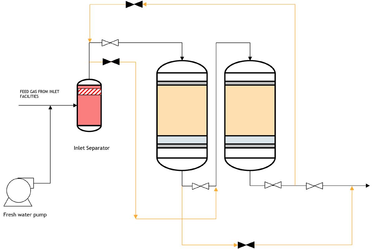
Several technologies are available from different manufacturers, and they can be divided into two groups: a) adsorbent requiring a water-saturated feed gas, and b) others.
More specifically, the first group requires the provision of water injection pumps upstream of the fixed beds to saturate the feedstock and the installation of a liquid separator with demister pad to remove free liquids from the gas stream. On the other hand, the second group does not require water-saturated streams: however, the H 2S removal performance is affected by the liquid carryover of the feed stream, which requires strict specifications. In these cases, an inlet filter/coalescer may be required and, for some other manufacturers, feed preheating may also be required to minimise the risk of liquid formation in the system. A typical lead/lag design provides the maximum flexibility in vessel configuration and the best efficiency; in fact, the gas flows through the lead bed first and then through the lag (or guard) bed. The spent adsorbent can therefore be changed without interrupting the plant operation and switched back into operation: lag bed becomes the lead bed while the lead bed is moved to the lag position (Figure 2).
Typical bed life for floating facilities is 4 – 6 months; in these applications, the life is often a trade-off between the layout constraints and the logistical management of fresh adsorbent and waste disposal.
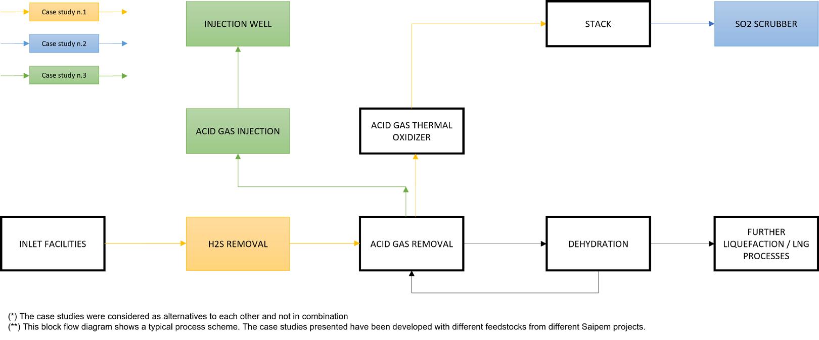
The first case study refers to a FEED developed by Saipem for a FLNG facility. The block flow diagram is shown in Figure 3.
The gas coming from the inlet facilities unit enters the AGRU with the aim of removing carbon dioxide (CO2) and traces of hydrogen sulfide from the feed gas stream, producing a sweet gas with acceptable levels of CO2 (less than 50 ppmv) for the downstream LNG liquefaction process. The AGRU process is a licensed design using proprietary amine solvent. The AGRU feedstock properties and sweet gas specifications are summarised in Table 1.
The resulting acid gas is sent to the acid gas thermal oxidiser (AGTO) to burn any hydrocarbon and to convert any sulfur compound to sulfur oxides (SOX), while the flash gas is sent to the AGTO as fuel.
The stream characterisation of acid and flash gas streams is listed in Table 2.
The resulting SOX emissions at the stack are approximately 1200 mg/Nm 3 dry (420 ppm mol), with 3% oxygen excess. This far exceeds the local environmental regulations for SOX emissions that limit this threshold to 600 mg/Nm 3 dry, 3% oxygen excess.
To solve the issue, a fixed-bed H 2S removal system upstream of the AGRU has been considered, in such a way that,
by maintaining the sweet gas specification indicated in Table 1, the H 2S content of the stream fed to the AGRU will be leaner, thus generating lower SOX emission.
To do so, the target H 2S composition at AGTO battery limits shall be lower than 180 ppm mol, with adequate margins; this threshold corresponds to an H 2S concentration lower than 0.7 ppm mol, downstream the non-regenerative beds.
The volume of the adsorbent was calculated to obtain the H 2S concentration at AGRU inlet mentioned in Table 3, guaranteeing a minimum bed life of six months for each vessel.
The size of the catalyst beds depends on the product and should be evaluated in conjunction with the type of feedstock conditioning. According to what was done by Saipem during the execution of the FEED, evaluated together with the client, the volume of the two vessels was selected to allow the accommodation of adsorbents from at least two of the manufacturers involved, in order to have more flexibility in the operation of the plant throughout its lifetime.
The provision of non-regenerative beds is therefore a suitable and attractive solution, in terms of layout and weight constraints and ease of operation to improve the restrictive SOX emission limits, which would not be achievable otherwise.
Another study under consideration was to scrub the flue gas from the AGTO stack with an alkaline solvent to remove SO 2 down to specification limits (Figure 3).
Due to considerations of required plot plan area, weight of equipment and piping involved, as well as dynamic factors due to the presence of wave motion become predominant for an FLNG facility, nonetheless the necessity of caustic water treatment, which can be problematic for this type of installation, the option under consideration was found to be less cost-effective than the others presented in this article.
The third case study is referred to a FEED developed by Saipem for an onshore gas treatment facility (Figure 1).
Similar to other previous case studies, the AGRU has been designed considering the CO 2 and H 2 S concentrations indicated in the Table 5.
Consequently, the acid gas resulting from the AGRU regenerator will result as indicated in the Table 6.
Also in this case, to meet the typical AGTO destruction conditions and efficiency (i.e. 99.5 – 99.9% at 880˚C), the resulting SOX emissions at the stack is approximately 4900 mg/Nm 3 dry (1700 ppm mol) at 3% oxygen excess, far exceeding any local and international environmental regulations.
To solve the issue, the disposal of such acid gas stream by means of injection into suitable locations has been considered, providing a sustainable and proven alternative. This solution not only avoids the SO 2 emissions from the management of the acid gas stream, but allows the sequestration and storage of 1.6 million tpy of acid gas (85 million ft 3 /d, 98% plant availability). A typical process scheme for the acid gas injection is reported in Figure 4.
The factors governing the selection of the most suitable acid gas injection process are several and include, but not limited to:
z Acid gas composition and process conditions.
z The site location.
z Disposal well location, geological conformation, and disposal pressure.
z Transportation route.
z Ambient conditions.
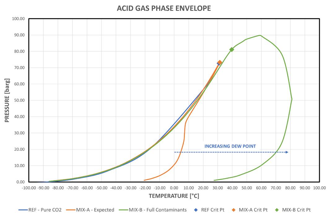
Even though the main component of the acid gas stream is CO 2 , the content of contaminants (i.e. BTEX and mercaptans) heavily affects the phase envelope of the mixture, thus affecting the physical, thermodynamic, and transport properties. In addition, considering that the upstream carbon capture process is amine-based, the actual acid gas composition may fluctuate, due to the fact that the actual affinity and selectivity of the solvent for such contaminants is neither controlled nor guaranteed by the technology providers (i.e. licensors or vendors). For this reason, it is of utmost importance to extend the compositional analysis of the contaminants beyond the expected values, so to properly design the acid gas conditioning and injection facilities. The effect of contaminants on the acid gas stream phase envelope is reported in Figure 5, where the phase envelope of the different acid gas streams is compared against the pure CO 2 .
Typically, an increased content of such species modifies the dew point of the mixture and may lead to additional material corrosion, safety, and environmental considerations.
Among the contaminants, water is key in acid gas injection facilities, since its content directly affects the dew point, hydrate formation, and material selection. The water content shall be reduced to a level which allows safe transportation up to the injection well, with no risk
of condensation or hydrate formation. Typical water content specifications depend on the storage site conditions and transportation routes, but 50÷150 ppm mol is a common consensus in industry practice.
The acid gas is received water saturated (4.8% mol) at 0.5 barg and 42˚C and compressed in the wet gas compression section up to 37 barg; as the pressure increases, the water is progressively knocked-out to 0.35% mol at 37 barg and 42˚C. Deep water removal can then take place at a convenient pressure by means of acid gas dehydration facilities.
Different water removal technologies can be investigated: a) glycol dehydration (TEG) or b) solid desiccant dehydration (i.e. molecular sieves or silica gel). As both the technologies are proven and effective, the selection of the best option comes down to a CAPEX/OPEX analysis, where the convenience of the technologies are compared against pros and cons in achieving the target specification.
Dehydrated acid gas can then be further compressed up to the required pressure level for transportation: 190 barg has been selected for this case study.
The required disposal pressure is normally determined from geological formation and life studies (i.e. early vs late life vs shut-in) of the injection well and transportation conditions (distance, onshore vs offshore routes and ambient conditions). Consequently, the selection of the compression scheme shall not only account for intermediate pressure for conditioning, but also for optimum energy efficiency all along the compression path. Even though the presence of contaminants alters the phase envelope of conventional CO 2-rich streams, supercritical fluid, or dense phase, conditions are also commonly reached: therefore, the threshold at which the ‘compression’ becomes a ‘pumping’ process shall be determined. Industry practice indicates that the supercritical acid gas pumping is efficient when the density of the dense phase is higher than 550 – 600 kg/m 3; consequently, the final pressure level for gas compression shall be selected to ensure that the density of the dense acid gas is adequately above these limits: minimum 110 barg for the purpose of this study.
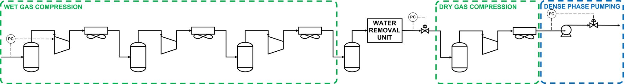
The overall compression/pumping process is summarised in Figure 6 on the same P-T phase envelope, assuming typical efficiencies for the machines and designing the compressor stages to provide optimal compression ratio (3.5).
The gas compression of an acid gas stream corresponding to 1.6 million tpy from 0.5 barg to 130 barg requires 20.8 MW, with an average of 160 kW/bar, while the dense phase pumping from 130 barg to 190 barg requires 0.6 MW, with an average of 10 kW/bar:
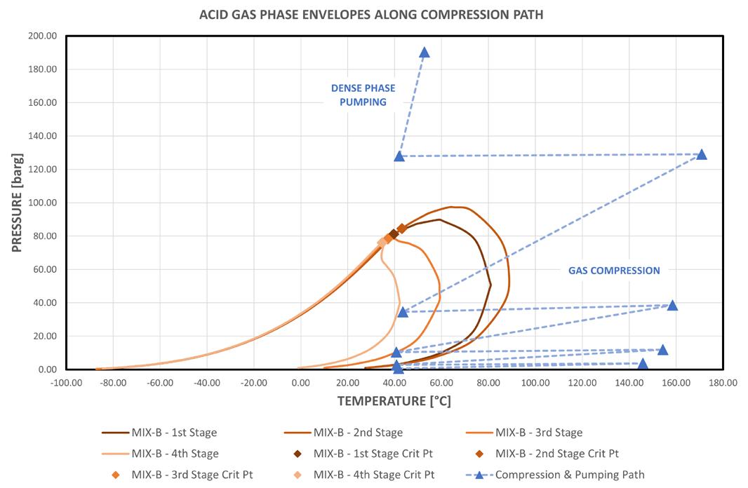
overall train power consumption is 21.4 MW. Therefore, the combined compression and pumping process allows the achievement of the required disposal pressure with increased efficiency due to dense phase pumping.
The three case studies presented in this paper are all effective alternatives intended to reduce the SOX emissions below the limits imposed by local or international (i.e. World Bank) regulations with different levels of convenience.
The first alternative is cost-effective for limited H 2 S contents in the feedstock and is advantageous in terms of ease of operation and installation.
The second alternative is certainly viable for onshore facilities, but has limitations for floaters applications.
The third alternative represents the most effective sequestration method but requires an available depleted reservoir for reinjection and storage.
LNG is produced by cooling natural gas to -160˚C. Prior to cooling to these low temperatures, impurities must be removed from the gas to ensure proper performance of the downstream liquefaction process. A standard pre-treatment line-up consists of an acid gas removal unit (AGRU), a molecular sieve dehydration unit to remove water to <0.1 ppm, and a mercury removal unit. It was not until the first baseload LNG plants in the US processing lean gas started up in the mid-2010s and began to experience freezing in the cryogenic heat exchangers that this typical pre-treatment approach was questioned. Only now, more than six years since the first mega scale LNG plant was built on the US Gulf Coast and 88 million tpy of capacity later,1 the industry has acknowledged and started to address the freezing problem, which reduces LNG throughput throughout the region.
The freezing of coldboxes in US LNG plants is due to traces of heavy hydrocarbons (HHCs) in otherwise lean natural gas, which are not removed prior to the cold section of the plant. Depending

Dr Tobias Eckardt, Dr Margaret Greene, Dr William Dolan, and Justin Pan, (BASF), and Stephen Holmes, Stephen Hughes, and Kevin Cunning (Kinder Morgan), outline how they addressed heavy hydrocarbon freezing while boosting yield at the Elba Island LNG Facility.

on the plant design, HHC freezing can occur as far upstream as the gas/gas heat exchanger upstream of the turboexpander. However, it is more common for the freezing to occur in the coldbox. US LNG plants have addressed the HHC freezing problem by reducing throughput or completely shutting down the trains to warm up the coldbox to derime. This process leads to flaring of natural gas and excess energy consumption due to warming and cooling of the coldbox. Another option is to run the coldbox at higher temperatures, which allows the facility to produce LNG continuously, but less efficiently. Even though the gas still meets LNG specifications, these mitigation practices also lead to plugging of heat exchanger filters in the sub-cooler skid on LNG tankers. Again, freezing causes cooling circuit shutdown and leads to more loss of LNG through boil off gas. Every plant must take a different approach to solve the problem of HHC freezing, but each approach adds complexity to operations and reduces the efficiency of LNG production.
Rather than sacrificing LNG production, BASF recommends removing the trace HHCs in the pre-treatment section of the plant. BASF has decades of experience producing and installing adsorbents for HHC and water removal from natural gas using temperature swing adsorption (TSA) technology. BASF Sorbead® aluminosilicate gel adsorbents are installed in some of the largest gas processing facilities in the world processing crude well gas to pipeline specifications.2 BASF has leveraged this experience to bring a new technology, DurasorbTM, to the LNG industry. Durasorb technology has been qualified by Shell, Exxon, and other gas majors, and has been implemented in a greenfield and brownfield plant. In this paper, BASF and the plant operator, Kinder Morgan, will detail the implementation
of Durasorb as a drop-in solution to coldbox freezing at the Elba Island LNG Facility.
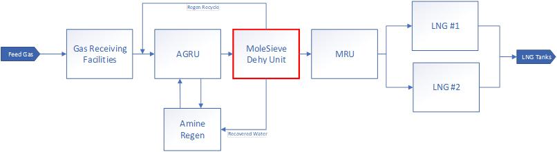
The ten 0.25 million tpy trains at the Elba Island Facility were started up over the course of 11 months from September 2019 to August 2020. The facility is fed from the US natural gas pipeline grid and employs Shell MMLS liquefaction technology. The pre-treatment line-up consists of an AGRU and dehydration unit. A simplified block diagram of the plant layout is shown in Figure 1. The dehydration unit consists of two towers, operating between 75 – 95˚F (24 – 35˚C), 730 psia (50 bar), on a 1440-minute cycle.
Because the pre-treatment line-up was not designed to remove trace HHCs, and these components are not efficiently removed in the liquefaction section of the plant, freezing of C8+ and BTX occurs in the cryogenic heat exchanger. The freezing of HHCs in the cold section requires plant operations to halt production for 1 – 2 days every 2 – 3 months on all 10 LNG trains. This workaround increases operational complexity, utilises personnel resources, and reduces annual LNG production.
In 2021, Kinder Morgan engineers began seeking a permanent solution to HHC freezing and reached out to natural gas experts in BASF. Together, three potential solutions were discussed:
1. Install a heavy hydrocarbon removal unit (HRU) upstream of the AGRU to process the full 400 million ft3/d of gas coming into the facility. This meets the HCC removal specifications for the entire plant, but requires the most cost and time, and has a single point of failure.
2. Install a third adsorber tower in each train. This meets HHC removal specifications for the individual train, but requires a high cost, time, and large plot space.
3. Replace the existing adsorbent material with Durasorb and utilise the current capabilities of the facility. This option has no CAPEX, a short time frame, and can be executed during a scheduled outage, but has limited benzene removal.
Understanding the capabilities and limitations of the current equipment at the facility was pivotal in predicting the performance of the unit if option 3 was chosen. Key pieces of equipment to understand when considering this option are the regeneration gas heater, cooler, and compressor capabilities. Option 1 would implement well-established HRU technology, which would utilise aluminosilicate gel material in a short cycle temperature swing adsorption (TSA) unit. This option would require significant CAPEX and time but would solve the problem for the whole plant and meet a benzene specification of <0.5 ppm. Option 2 would utilise the current infrastructure but add a third adsorption tower to each train. This option would provide more HHC removal, but also
require CAPEX and time, and the facility did not have the plot space. Option 3, implementing Durasorb as a drop-in solution, is the simplest option, using the existing infrastructure of the plant, but is expected to remove the least amount of HHCs prior to the cold gas separator.
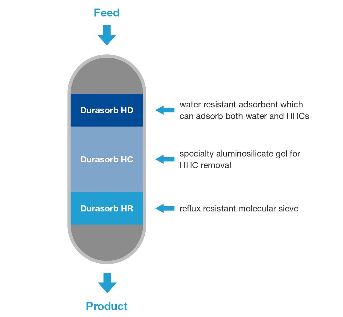
Durasorb technology combines the performance of an HRU for HHC removal and a dehydration unit for water removal to cryogenic specifications. The main challenge with combining HRU and dehydration technology is the lifetime of molecular sieves. In an HRU, BASF utilises aluminosilicate gel materials, which are robust and can withstand upwards of 10 000 cycles in a lifetime. On the other hand, molecular sieves are required to achieve very low water specifications but are not robust materials and can only withstand 1200 – 1500 cycles in a lifetime. Combining aluminosilicate gel materials,3 which are the most well-suited materials for adsorption of heavy hydrocarbons (C8+, BTX), and molecular sieves in the same unit requires the molecular sieve materials to match the lifetime of the aluminosilicate gel materials.4 Durasorb technology utilises a proprietary bed design that necessitates most of the bed to be filled with the more robust aluminosilicate gel material and a small section of the bottom of the bed with molecular sieve (Figure 2). This approach protects the molecular sieve from HHCs and most of the water, which allows the molecular sieve to last longer and be cycled more frequently.5
In early 2022, Kinder Morgan decided to move forward with a trial of option 3, which was the quickest to implement and required no CAPEX. This option also provided Kinder Morgan with a side-by-side comparison, replacing molecular sieve with BASF’s Durasorb material in two of 10 trains. Initial analysis also showed there was ample regen gas, which would allow for cycle time optimisation and performance improvement. Since the implementation in July and August 2022, BASF and Kinder Morgan have worked together to monitor and optimise the performance of the Durasorb trains.
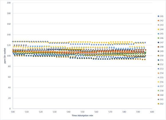
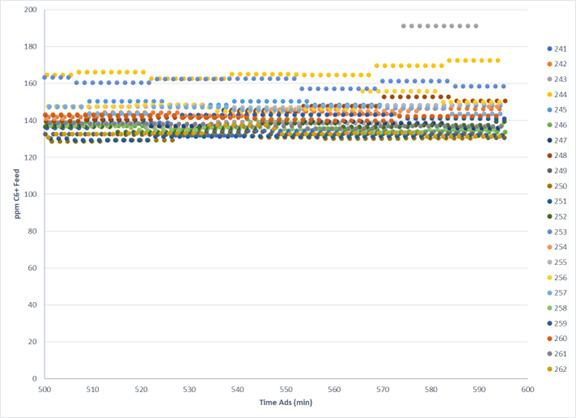
LNG trains at the Elba Island Facility include a moisture analyser and online GC measuring C6+ and benzene concentration. Upon start up with Durasorb technology, the LNG trains were processing 38 million ft3/d of gas and removing water to LNG specifications. Although removing water is of utmost importance, the goal of this project was to address the freezing problem, which is caused by benzene and C8+ components. As shown in the Figure 3, feed gas composition includes ~7 ppmv of benzene and ~150-200 ppmv of C6+. Comparing C6+ inlet and outlet GC data shows removal of about 30-40 ppmv of C6+.
Further analysis and manipulation of the data indicates that the removed C6+ are C8+ components.
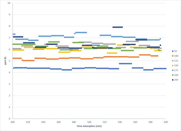
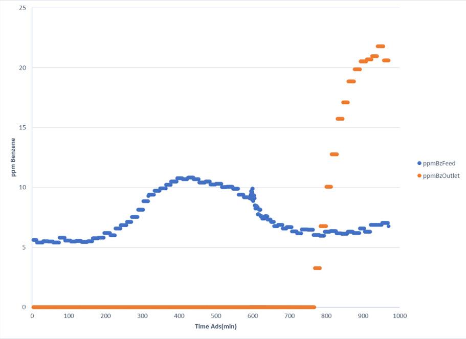
As a known freezing impurity, the removal of benzene was also monitored. Inlet and outlet GC data are shown in Figure 4. The data shows benzene removal from an average of 7 ppm inlet to undetectable levels at the outlet. Benzene continues to be removed over many cycles and has been consistent since startup of the Durasorb trains.
In addition to GC data, regeneration separator liquid volume was monitored to confirm heavy hydrocarbon removal performance of the adsorber beds.
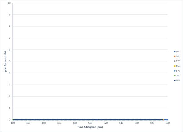
Based on data provided by Kinder Morgan, BASF recommended reducing cycle time from 720 min. to 590 min. Shorter cycle time allows the unit to remove more HHCs, taking a deeper cut of C8+ and benzene. As shown in Figure 5, benzene breakthrough occurs at 770 mins., therefore, ending the adsorption time sooner than 770 mins. ensures complete benzene removal. Running the unit to breakthrough gave BASF and Kinder Morgan additional data for benzene adsorption, confirming BASF’s simulation model, and showed that occasional breakthrough of benzene does not lead to permanent increase in coldbox dp.
A result of the Durasorb technology achieving the desired performance of removing HHCs and water is the presence of HHCs in the regen liquids normally routed back to the AGRU. Due to the scale of each LNG train at the Elba Island Facility, operations can dispose of the contaminated liquid stream and make up water losses at a negligible cost, rather than recycling back to the AGRU. For greenfield projects or retrofits of larger LNG trains, a three-phase separator represents the most desirable solution for the regeneration condensate to facilitate separate handling mechanisms for the water and hydrocarbon streams. Alternative liquid handling solutions can also be considered depending on the plant line-up and operational needs. Recycling the regeneration condensate back to the front of the AGRU may be possible depending on the amount of hydrocarbon liquids removed.
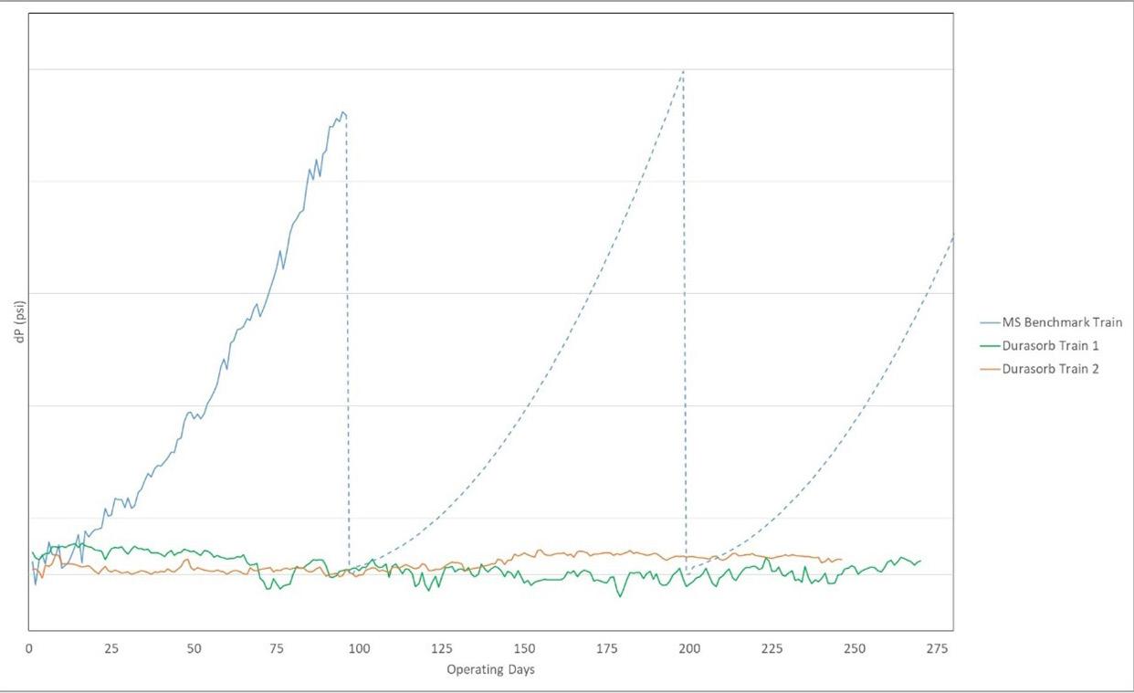
As of the date of paper submission (28 June 2023), the two Durasorb trains at the Elba Island Facility continue to remove water and HHCs to the levels described in this paper. Most importantly, the pressure drop in the coldbox remains flat and natural gas has been processed through these trains on a continuous basis, without requiring shutdown for deriming. Figure 6 shows how the pressure drop in the Durasorb trains remains steady, as the pressure drop in the molecular sieve trains continues to increase until shutdown and deriming are required. Durasorb trains have run for over 330 days and eliminated three deriming events that would have required a production stoppage. The Durasorb trains continue to run well, with no indication of solids build up, and plant data indicates that the expected four-year lifetime will be achieved.
BASF worked with Kinder Morgan to identify a solution to coldbox freezing that would have the desired impact in the shortest amount of time. BASF and Kinder Morgan worked together to implement Durasorb technology in two out of 10 trains at the Elba Island LNG Facility. The two trains operating with Durasorb materials are removing HHCs and water and preventing deriming events.
Implementation of Durasorb has increased uptime at the Elba Island Facility. Kinder Morgan has been pleased with both the performance of the Durasorb technology and the support provided by BASF. With that, Kinder Morgan has decided to replace existing molecular sieves with Durasorb technology in three additional trains this year, bringing the total Durasorb trains at Elba Island to five. In addition, Kinder Morgan is planning a full 10 train upgrade project, which will utilise Durasorb to remove heavy hydrocarbons and allow the gas to by-pass the cold gas separator. Bypassing the cold gas separator allows operations to run at higher pressure throughout the process and keep the gas above critical. This process change, along with auxiliary equipment upgrades, is expected to reduce the frequency of outages and flaring emissions associated with deriming and increase production throughput at the Elba Island Facility.6
1. STADNYK, M., GODVIG, T., and BOGGS, S. P., ‘The rise to the top for US LNG’, LNG Industry Magazine, (March 2023).
2. HEYWOOD, M., UHE, M. (Spirit Energy), ECKARDT, T., GREENE M. A., RACHER, R., and WYATT, R. (BASF), ‘North Morecambe onshore terminal adapts to changing feedstock’, Oil and Gas Journal, (2020).
3. GREENE M. A., ECKARDT, T. (BASF), ADAM, J., PETERS, P. (EG LNG), ‘Innovation in Dehydration’, LNG Industry Magazine, (May 2022).
4. ECKHARD, T., ‘Innovation in Materials Development for LNG Dehydration’, LNG19 Conference, Shanghai, China, (April 2019).
5. GREENE, M. A., DOLAN, W., PAN, J., MAGLIO, A., ECKHARD, T. (BASF), BOERRIGTER, H., SMALING, and M., RUSLIi, I. (Shell), ‘Coming out of the ice age’, LNG Industry Magazine, (May 2021).
6. Federal Energy Regulatory Commission Application Docket No. CP23-375-000, filed 10 May 2023.
This article is based on a paper presented at LNG2023. It has been published with the approval of the LNG2023 Conference.
New designs, installations, and a move to future-proof ships by using tanks that are future fuel-ready, are some of the major trends within LNG storage technology.
2022 saw a first for the industry when Oslo-based shipowner, Höegh Autoliners, announced that its new Aurora Class car carriers will deploy LNG tanks, capable of being converted to operate on ammonia or methanol in the future. The eight multi-gas tanks, which have been granted DNV’s ammonia and methanol-ready notations, are the first in the pure car, truck carrier (PCTC) segment that are capable of being converted to operate on zero-carbon ammonia.
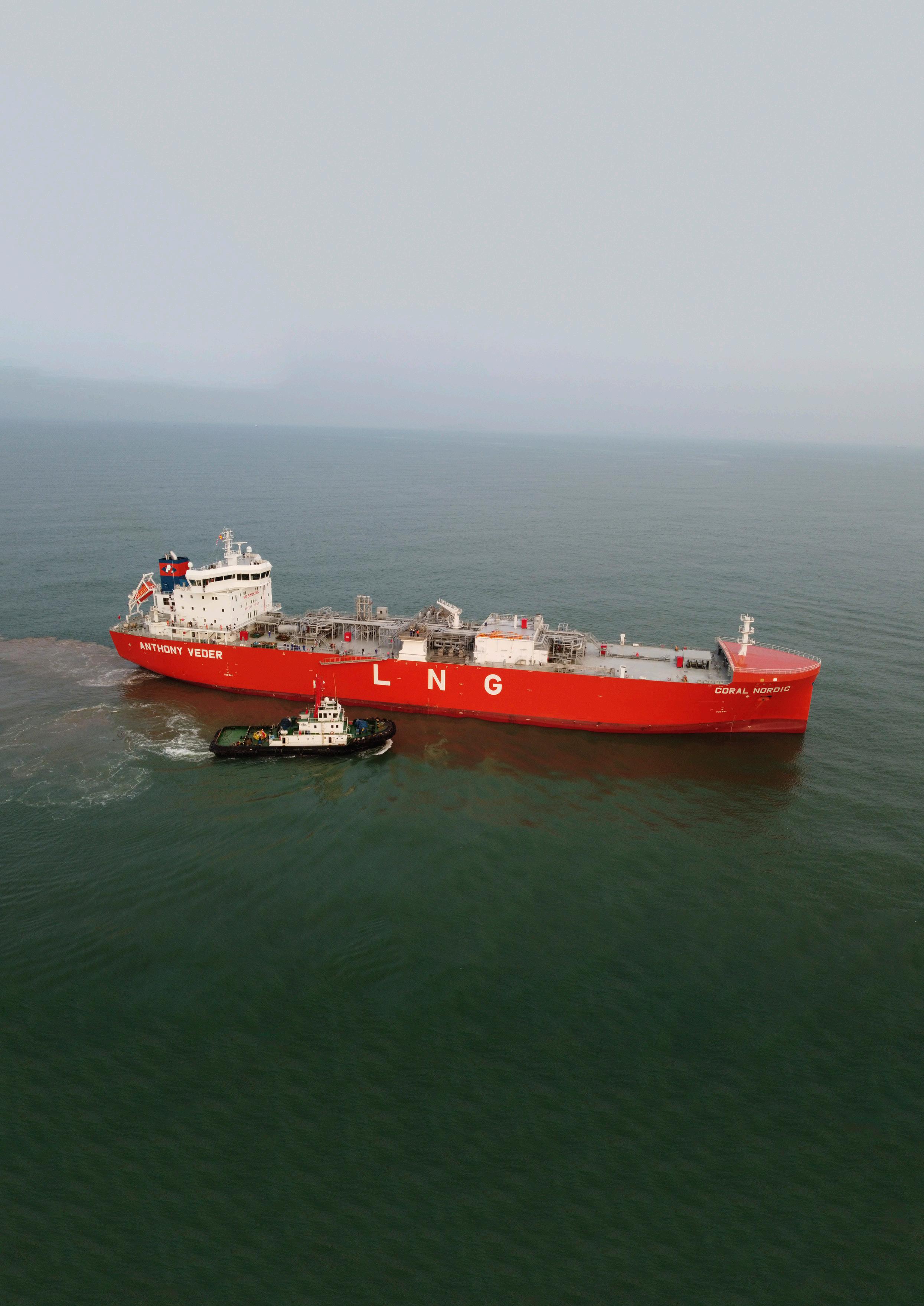
The eight vessels, which will be the largest and most environmentally-friendly car carriers ever constructed, are being built by Chinese shipbuilding group, China Merchants Heavy Industry.
TGE Marine Gas Engineering is supplying fuel gas systems and multi-fuel gas tanks.
This multi-fuel gas tank concept allows ship owners to prepare for the 2050 net-zero emissions regulations
while saving significant time and money. Having a methanol or ammonia-ready tank means that when they want to switch from LNG to a non-carbon fuel, they only have to change the fuel gas plant. The motive for Höegh Autoliners’ decision to use this concept was that the ship operator can deploy LNG until ammonia and methanol engines are developed, allowing it to then switch to better its carbon-dioxide efforts.
There are several considerations and challenges to consider when designing and deploying multi-fuel tanks. The properties and requirements of each fuel needs to be carefully considered in order to choose the right tank material.
The fuel temperature is particularly challenging: LNG, for example, needs a very low -165˚C, while in contrast, ammonia only needs to be stored at -35˚C. Another issue is the material of the tanks in which the gases are stored, as ammonia can create cracks in the high-strength nickel steel currently used for LNG tanks due to its corrosive behaviour. A third major issue is the difference in weight as both ammonia and methanol weigh more than LNG.
Frank-Torsten Appel, TGE Marine Gas Engineering, Germany, explains how new configurations and preparing for the future are shaping the market.
An additional consideration with methanol is that, unlike LNG and ammonia, it is a liquid in atmospheric conditions, so there is no need to pressurise it. Methanol is heavier than ammonia, but because no pressure is needed, the balance between the heavy fuel and the low pressure can be found by optimising the weight of the tank.
The material chosen for Höegh Autoliners’ fuel tanks that can address these issues is stainless steel.
The deployment of multi-fuel tanks is likely to be a trend until main engines for methanol and ammonia are fully developed, which will allow the shipowner to make a choice of fuel before building the ship. But until such engines are ready, LNG tanks that are future fuel-ready are an important, intermediate step to a non-carbonised future.
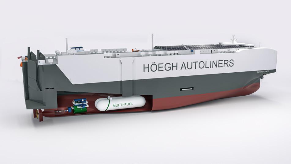
Another development within LNG storage technology is the configuration of bi-lobe type C tanks, designed to reduce both the space needed and the width of the ship, it cuts the installation time and hugely reducing CAPEX costs. This is illustrated by the construction of Anthony Veder’s 30 000 m 3 LNG carrier, Coral Nordic, completed last year, which has installed the world’s two largest bi-lobe type C containment tanks. Provided by TGE Marine Gas Engineering, the tanks are designed for a maximum design pressure of 4.80 barg and a minimum design temperature of -164˚C.
Normally this type of LNG carrier deploys three bi-lobe tanks. However, in a first-of-its-kind for its size, in Coral Nordic two tanks were used, one of 16 000 m3 and one of 14 000 m 3. A main advantage of using two tanks is that compared to three tanks, the tank arrangements are reduced, with less pumps, valves, and instruments required. Challenges to overcome include the supporting of the greater weight of these tanks compared to a three-tank configuration. A 16 000 m 3 LNG tank creates 8000 t of weight compared to only 6000 t of a 12 000 m3 tank used in three-tank configurations.
The supports for these tanks on the ship have to be able to take on this extra weight. Both tanks are resting on TGE Marine’s patented special foundation design, allowing the tanks to shrink unimpeded at low operating temperatures. The patented support design turns the conventional load bearing and thermal insulation layer into a flat plane, avoiding shrinkage between the tank support and foundation, other than along this flat plane.
Saving space is also a key driver for other ship types when it comes to LNG containment systems, especially for container ships and retrofit projects within this sector. LNG container ship retrofits were kickstarted with the conversion of Elbdeich Reederei’s 1036 TEU ElbBlue (ex. Wes Amelie) –now Seaboard Blue and owned by US line, Seaboard Marine – in 2017. This project was considered a milestone as it showed the industry that it was possible to successfully retrofit container ships. Here, cargo space loss was reduced by installing cylindrical fuel tanks in the forecastle. But in the years since, new configurations to maximise loss of cargo space have been developed.
TGE Marine Engineering developed a patented tri-lobe tank in 2019 to meet this requirement. A tri-lobe Type C tank is optimised to use just one container slot on a medium or large container vessel. A horizontal transversal arrangement of three cylindrical sections is deployed, creating three lobes. This compact arrangement lessens the work needed to modify the ship design and boosts volumetric efficiency. Up to 7000 m 3 LNG capacity tanks can be offered through this design.
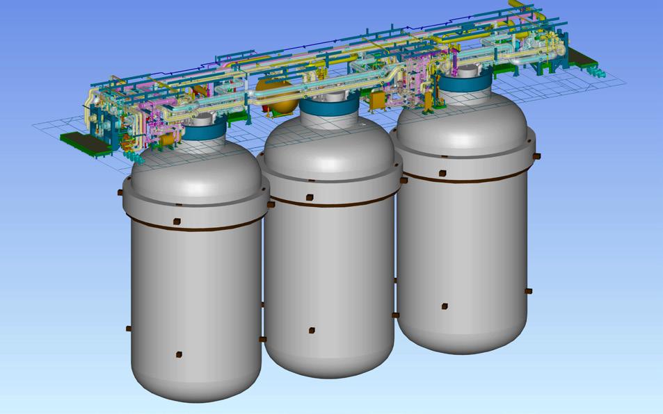
Another method to save cargo space is the deployment of three vertical tanks placed over the width of the vessel. The first projects where this configuration was used included for six Containerships 1400 TEU vessels: Nord, Aurora, Polar, Arctic, Borealis, and Stellar. Between 2018 – 2020, three 230 m³ cylindrical fuel gas tanks were vertically installed in the container bay of each vessel. Heerema’s semi-submersible Sleipnir crane vessel,
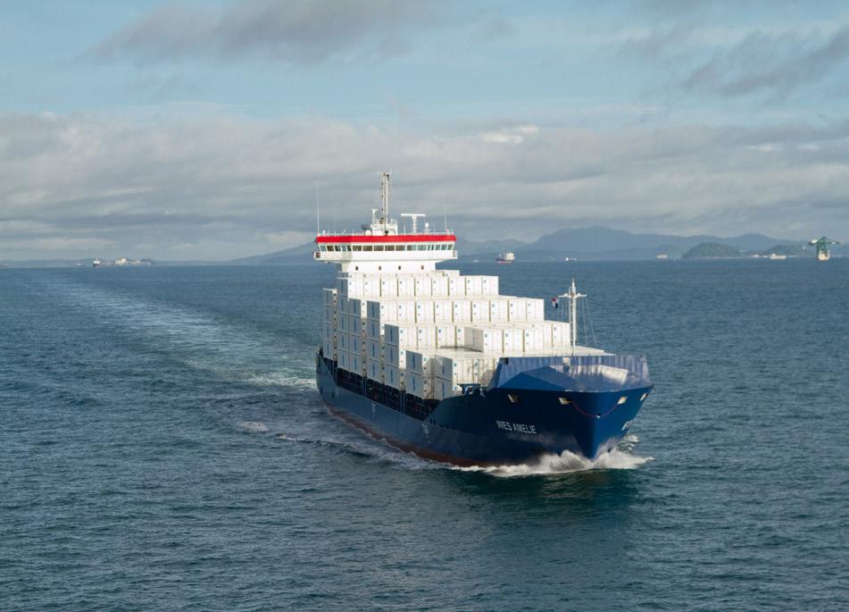
completed in 2019, also features one of the first applications with TGE Marine’s vertical Type C arrangement. This first-of-its-kind offshore crane project with LNG propulsion was one of the first applications with TGE Marine’s vertical Type C tanks. The system consists of a four-train LNG fuel system providing gas fuel to four engine rooms with full redundancy based on the DP notation of the vessel. Eight 1151 m³ panel insulated fuel gas tanks were vertically installed. There was no space for a horizontal arrangement of the tanks at the base of the ship, but with sufficient height for vertical tanks, this configuration was able to be installed.
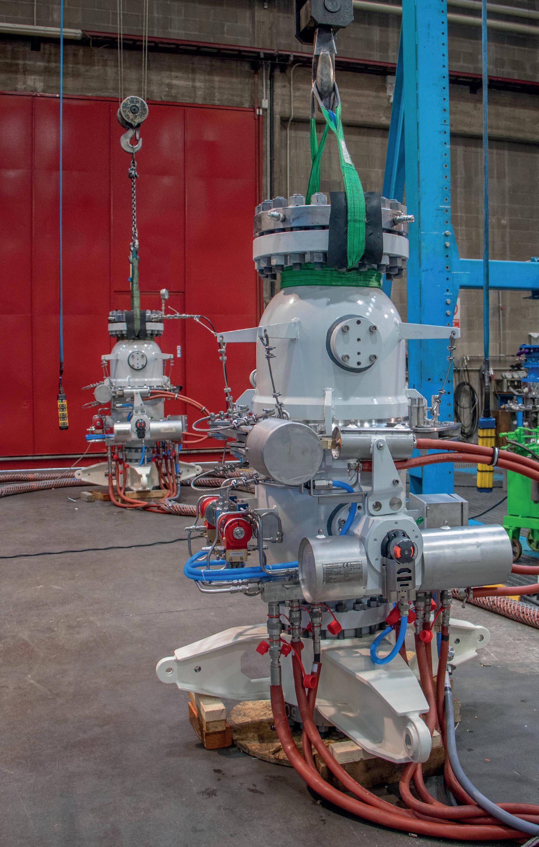
Elsewhere, strides have been made to reduce the generation of boil-off gas (BOG) as well as use it as a fuel itself. Insulation is key to reducing the BOG rate, and here the industry has made developments over the past decade.
Coral Nordic is a good example to use. A PU spray foam insulation system was applied, leading to a very low BOG rate of 0.15%/d. This state-of-the-art insulation system is the successor of a long development starting with an insulation system for LPG containment technology approximately 25 years ago.
Coral Nordic’s tank arrangement also shows how deploying two large bi-lobe tanks instead of three can reduce the BOG rate. The tank supports and dome connections are the most vulnerable areas for heat to be lost. By having two tanks, where the number of supports is reduced to four, vs six supports for a three-tank arrangement, heat loss is saved, and the total volume of BOG rate is reduced.
Once the containment system has been insulated as much as possible, there are several options when it comes to dealing with BOG. One possibility is to burn it in the main engine; another is to re-condensate it and bring the liquid back to the tank; and the third option is to burn it in the gas combustion unit. The last option is the least efficient method. Using BOG as a fuel is a good option, especially as it is difficult, and energy consuming, to conduct a reliquefication of the natural gas.
For engines requiring high fuel gas supply pressure of 300 bar, compressing BOG to this pressure is both challenging and expensive. These high-pressure compressors also have high OPEX costs. Höegh Autoliners’ car carriers demonstrate an efficient and innovative way to handle and reuse BOG as fuel, with a newly developed re-condenser system. This re-condenser system brings the BOG back to the tank as liquid, which is then used to serve the main engine. The system cuts opex costs and boosts the reduction of greenhouse gas emissions.
The drive to decarbonise is starting to shape the market when it comes to LNG containment systems. Höegh Autoliners’ milestone new car carriers mark the
The liquification of natural gas enables up to 600 times more energy to be transported for the same volume using LNG carriers. To convert natural gas into LNG, it must be cooled down to the cryogenic temperature of -162˚C. Today’s large-capacity LNG carriers, consisting of four tanks with a total transport volume of around 175 000 m3, require perfect insulation and sealing of the two containment barriers.
Hutchinson Precision Sealing Systems, a subsidiary of TotalEnergies, is seeking to support the development of LNG with its extraction and production projects. With this in mind, the company has developed solutions that act as barriers, insulation, and protection of structures in direct contact with LNG.
To bring a performant and safe solution to the LNG industry, Hutchinson developed Triplex, to ensure the sealing of the secondary barrier on LNG tanks; specifically LNG carriers using Mark III technologies.

For over 30 years, the company has been a supplier of the flexible secondary barrier on Mark III LNG tanks designed by the French company, GTT. Triplex is used for the tightness and safety of the LNG tanks on more than one-third of the world’s LNG carriers, with over 240 references, including LNG carriers, ground storage tanks (GST), floating LNG units (FLNGs), FSRUs, onshore storage tanks, LNG fuel tanks, and bunkering vessels. This was the case on the first prelude (FLNG); on the first fuel tank; on the first gravity-based structure (GBS); for Arctic LNG; on the argon tank for Cern; and for the arctic cruise ship Le Commandant Charcot of the Ponant company.
Triplex-FR (F standing for ‘flexible’) is a supple composite membrane that is LNG tight at -162˚C, not only during normal operation –which is around -100˚C – but also in the event of a problem on the
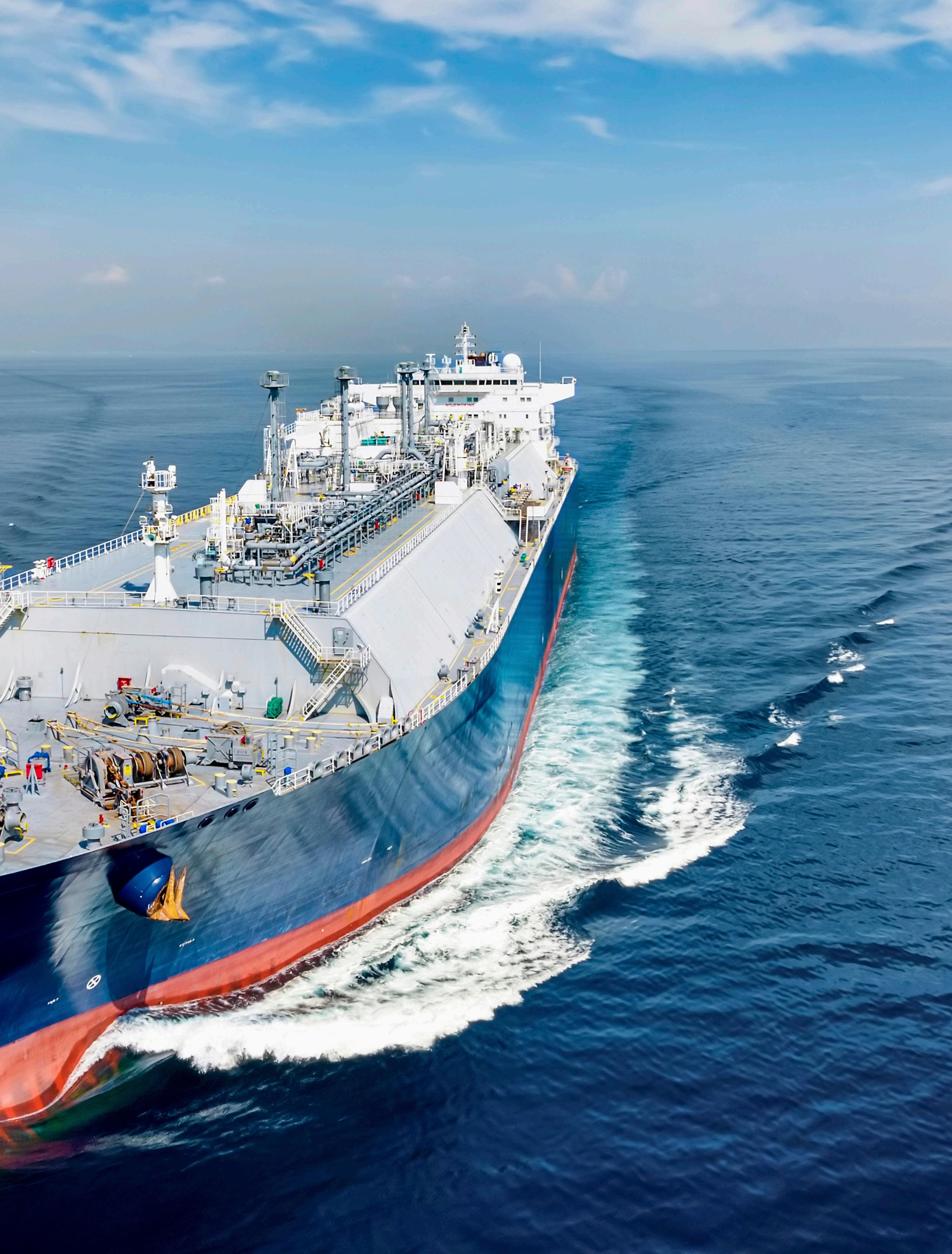
primary barrier when it will be at -162˚C and in direct contact with the LNG. Its flexibility allows it to absorb the thermal contractions of the LNG tanks, as well as the deformations of the vessel’s structure received while at sea.
To increase the performance and safety, the company has also developed a second variant of Triplex, called Triplex-R ® . The Triplex-R (R standing for ‘rigid’) is the firm secondary barrier, to which the aforementioned membrane is attached to help seal the containers. When used in conjunction, Triplex-R is bonded onto RPUF – which is the main component of the insulation panel (IP) – and Triplex-F is bonded onto the Triplex-R to ensure a seal between the two panels. Figure 2 depicts how the two barriers are bonded to ensure a completely tight secondary barrier of the LNG tanks using Mark III technologies.
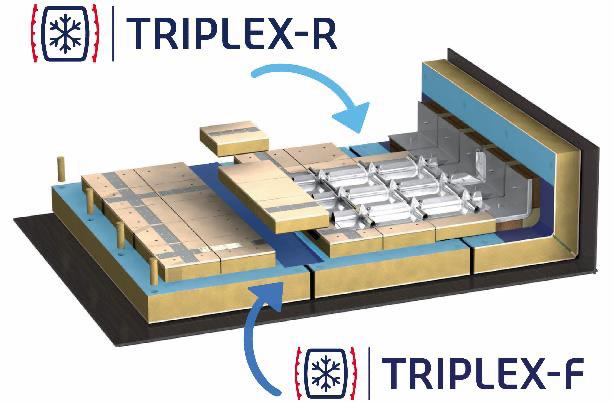
Hutchinson Triplex is made of three layers, two of glass cloth, and one of aluminium foil. The flexible Triplex is delivered in rolls with various widths (maximum of 1250 mm) and lengths (maximum of 50 linear m) and the rigid secondary barrier in sheets with the most standard dimension of 3 x 1 m.
At cryogenic temperatures of -162˚C, safety is fundamental, especially in the transport of LNG by its carriers. The growing use of LNG in the world has led to shorter lead times and higher quality standards, enabling them to reach expected safety and performance.
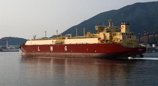
Hutchinson supports its customers and partners in new developments by supplying Triplex-F and Triplex-R with successfully applying on GSTs in China and GBSs in Russia. The company succeeded in obtaining Triplex-R approval by GTT and by classification societies, such as Lloyd’s Register,
for offshore applications in August 2022. With this approval, Triplex-R complies with all GTT technical requirements and is approved for use as a secondary barrier and as reinforcement under top bridge pads in the construction of GTT Mark III LNG containment systems. Such approvals require many steps to be validated for use on upcoming projects such as fuel tanks, LNG carriers, and more:
z First, the tightness of Triplex-R has been tested at cryogenic temperature.
z Secondly, its resistance to mechanical stresses due to thermal contraction has been carefully checked through multiple mechanical testing at both ambient and cryogenic temperatures (peeling test, shearing test etc.), which are representative of real conditions inside LNG carriers.
z Then, chemical compatibility with methane and sea water has been tested to certify that no issue will appear in case of failure of the primary barrier.
z Finally, Triplex-R has been tested with several glues and components already approved in the Mark III system.
As a result of this new certification, the company can provide this complete secondary barrier for any project at any construction site and therefore open up to new market opportunities, putting its expertise at the service of its customers.
One of the most important hazards on LNG carriers, onshore and offshore platforms and structures is the cryogenic liquid. It is therefore mandatory to study, design and install cryogenic spillage protection (CSP) and passive fire protection (PFP) in certain areas or structures. To protect the structures with CSP, the company has developed Zaltex ® , another two-in-one innovative solution.
Zaltex is a light and rigid composite material specifically designed and developed. Zaltex, delivered as panels, can be used as CSP and PFP on LNG carriers, onshore and offshore structures, among others. Zaltex offers mechanical strength, as well as resistance at high and low temperatures. It is resistant to cryogenic temperatures as low as -192˚C without any cracks nor damage, making it suitable for cryogenic applications, while also providing fire protection at high temperatures. Zaltex has been used on a large LNG extraction plant to protect the MCHE modules on the three trains in case of accidental cryogenic spillage of the LNG.
Its thermal conductivity and insulation properties allow a CSP/PFP solution by Zaltex that is much thinner and lighter compared to other existing solutions.
Due to its light weight and thin design, Zaltex offers an effective performance to thickness ratio. For example, it withstands the most severe cold tests for two hours with a thickness of only 21 mm and a density of 18 kg/m³. Zaltex is light, modular, and easy to assemble under any weather conditions and, as its thermal expansion is very similar the one of the steel, no stress shall be generated when there
are temperature variations. This makes it suitable for LNG plants, chemical equipment, drilling or production facilities, storage or transportation.
To attest to its CSP performance, Zaltex was certified according to ISO 20088-1 and -3 to the ISO 20088-1 in March 2021 by DNV Spadeadam under the supervision of Lloyd’s Register. This solution withstood a two hour jet release at -196˚C while maintaining its integrity and remaining intact. It also prevented the structural steel from reaching the critical temperature of -44˚C after two hours.
This test has been repeated several times on the same Zaltex mock-up with its properties, integrity, and tightness remaining the same.
Rubber cellular foams
Hutchinson also designs and manufactures a full range of EPDM foams under the brand name Bulatex ® . From very soft to hard, Bulatex exists in both closed and open cells. It is a solution adaptable for all needs: shock absorption, anti-vibration, wedging, sealing (air, liquids, dust), acoustic insulation, NVH, thermal insulation (i.e. cryogenic temperatures).
The closed cell foams guarantee a perfect sealing at low compression and the open cell foams – or sponge foams –ensure sealing while adapting to all geometries (shape defects, large tolerances, etc.) due to their high compression capacity. Bulatex foams are also fire resistant and compatible with FMVSS 302 certification:
Join us in our mission for a sustainable maritime industry. In 2023, we're proud to introduce two 100% electric tugboats to our versatile fleet, reinforcing our commitment to environmentally responsible operations and innovative solutions. The new fleet will be heading for the port of Vancouver in Canada, where they will be completely carbon neutral and reduce 2,400 tons of CO2 annually.

Count on SAAM Towage for all your towage needs. Our dedicated team and state-of-the-art fleet ensure we meet the diverse requirements of maritime operations. Let's discuss how we can deliver exceptional service tailored to your specific needs. Together, we'll create a better future.
z Load-bearing capacities from 2 kPa to 1500 kPa.
z Thermal conductivity from 0.035 W/m˚C.
z Hardness from 55 Sh00 to 50 ShA.
z Temperature: from -50˚C to 150˚C.
z Options: fitted with adhesives (transfer, non-woven, mesh, hot-melt).
Other materials for foam cell converting: polyurethane (polyester and polyether), polyethylene, PVC, rubber (open cell and closed cell), felt and felttrine, and airbag net.
The flexibility of these materials offer solutions for different applications and adapts them to customer specifications.
Triplex-R has been added to the range of cryogenic solutions to ensure sealing and insulation protection of oil and gas structures.
The combination of Zaltex panels and Bulatex foams has led to the development of battery spacers for electric and hybrid vehicles, ensuring watertightness, fire resistance in the event of thermal runaway, and vibration absorption during driving.
The company contributes to future mobility by
13 countries +60 years of experience
Brazil Colombia Operations are 100% Carbon Neutral*
2 electric tugboats +90 ports +210 tugboats SAAM Towage

NG carriers have undergone a continuous design evolution over the last two decades, comprising different propulsion solutions and tank arrangements, including ship designs with more efficient reliquefaction and gas handling systems.
Today’s LNG carrier designs need to be flexible enough to consider the impact of tightening regulations and the need for optimised performance. The second area of focus for LNG designers is in the choice of cargo containment systems (CCS) and the steady evolution of system performance to optimise boil-off gas (BOG).
After regasification, 1 m3 of LNG produces approximately 600 m3 of natural gas. In terms of safety and overall efficiency, the main issue is to maintain the LNG cryogenic condition at -161˚C and, for that, different CCS can be applied. These are all categorised in the International Code for the Construction
and Equipment of Ships Carrying Liquefied Gas in bulk (IGC Code).
LNG containment systems are divided into two main categories: independent tanks (Types A, B, and C), which are not directly part of the hull of the ship, and integrated tanks (membrane tanks), where the tank is part of the hull.

Independent Type A tanks are designed using the traditional method of ship structural design (with a prismatic shape), and are commonly used for liquefied petroleum gas (LPG) carriers, carrying LPG at near-atmospheric conditions or LNG at a design pressure less than 700 mbar.
Such tanks are primarily constructed of plain surfaces with some insulation on the outside. The material used for tank construction is not resistant to crack propagation and, in the
Tank systems for LNG cargo have evolved over time as demands have changed and new approaches have emerged, writes
Sebastien Le Moigne, Global Gas Solutions Manager, ABS.
unlikely event that the tank does crack, the surrounding space should be capable of holding the entire tank volume at any heel angle.
Application on LNG carriers requires a full secondary barrier to avoid brittle fracture due to the cryogenic state of the gas. The space between the tank and the hull is known as the hold space and, when carrying flammable cargoes, this space must be always inerted to prevent a flammable atmosphere from forming in the event of a leakage in the primary barrier.
Until a decade ago, the need for a full secondary barrier was always a technical and/or economic showstopper for the use of Type A tanks on LNG carriers. This changed with the development of the LNT A-Box® system by LNT Marine, using an insulation system fixed to the ship’s hull with a liquid-tight inner surface to contain any leak from the cargo tank.
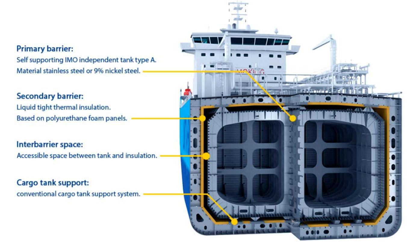
The first LNT-equipped LNG carrier was the 45 000 m3 Saga Dawn, contracted by SAGA LNG Shipping with CMHI Shipyard and built to ABS Class in 2015. The system was primarily designed for small and medium sized LNG carriers but a 175 000 m3 design from LNT Marine was recently approved in principle by ABS, as well as a LNT fuel-box system which can be deployed on ships designed to use LNG as a fuel.
Torgy’s LNG A-Tank has further refined the conventional Type A tank design. The design uses a metallic barrier with thin plates of stainless steel, arranged to handle the cryogenic environment and the challenging effects of cooldown during operation.
Torgy LNG has patented the design and layout for this innovative fishbone pattern, which releases the stress in membrane plates during cooldown. This system is more suitable for small scale LNG carriers and LNG fuel tanks, providing an alternative to Type C tanks thanks to greater space efficiency.
The concept behind Type B tanks is to have a structure in which a crack can be detected long before failure occurs. The methods used for tank design include determination of stress levels at various temperatures and pressures by first principal analyses, determination of fatigue life of tank structure, and study of crack propagation characteristics.
The enhanced design of such tanks requires a partial secondary barrier, and this takes the form of a drip pan placed below the tank bottom while insulation is applied to
the outside. The Type B spherical tank is the most common and is almost exclusively applied to LNG carriers. Type B tanks do not need to be spherical. There are Type B tanks of prismatic shape in LNG service and this has the benefit of maximising deck space, though where the prismatic shape is used, the maximum design vapour space pressure is limited to 700 mbar.
The most successful and recognisable Type B tank is the spherical CCS developed by Moss Rosenberg Verft in 1973, which in use on around one-fifth of the LNG carrier fleet. The system features self-supporting spherical tanks, removing any sloshing concerns, connected at the equator to a single cylindrical supporting skirt, the lower portion of which is welded to the ship structure. The tanks are made of aluminium alloy, with internal diameters above 40 m and a shell thickness of up to 50 mm.
Insulation using polyurethane, Styrofoam, or equivalent is arranged over the tank’s outer surface and the upper part of the skirt. Most Moss-type vessels have four or five tanks, and they are checked for any leakages by nitrogen atmosphere in a special ‘tinfoil’ layer, which also allows the insulation to remain dry. These tanks are susceptible to contraction and expansion of up to 0.6 m during cool down and warm up, so all piping enters the tanks through the top and are connected to the ship’s lines via flexible bellows with a bell shape structure on the base to absorb these variations.
The equatorial skirt is also constructed to endure changes in tank diameters, as well as having the strength to successfully transfer the tanks’ weight to the ship’s hull. The pressure in these tanks, not being prismatic, allows a higher design pressure at 2 bar.
Net tonnage is derived solely from ship’s dimension and not from cargo capacity or its load. Moss type LNG carriers, having half the spherical shape protruding above the deck, will pay more per cubic metre of LNG in tolls and fees when transiting canals, which impacts voyage costs. The design also has an impact on the ship’s aerodynamics, being more subject to wind forces than membrane tanks with a resulting impact on fuel consumption.
Mitsubishi Heavy Industries, Ltd (MHI) has developed a next-generation spherical CCS using a continuous tank cover. Nicknamed Sayaendo, meaning ‘peas in a pod’, the first order for this vessel type was placed in 2012. In a Moss-type LNG carrier, the upper portion of the spherical tanks above the ship’s upper deck is protected by a semispherical cover and the lower portion under the upper deck is supported by a cylindrical skirt structure.
By contrast, the Sayaendo design employs a continuous cover running the length of the ship, integrated with the ship’s primary strength members, to house all tanks under one roof while maintaining the necessary compartment divisions. This helps contribute to the overall structural strength and enabling hull weight reduction.
In 2017, Kawasaki Heavy Industries, Ltd (KHI) announced that it had obtained approval in principle for a new Moss-type LNG storage tank. This concept takes a new approach by applying a non-spherical tank design to improve the use of space. The non-spherical design concept allows panamax-size LNG carriers to increase their total carrying capacity by 15% when compared to using spherical tanks.
Japanese shipbuilder, IHI, developed a Type B cargo containment system based on self-supporting prismatic tanks, called SPB Tank, which was completed in 1985. Two 87 500 m3 LNG carriers, Polar Eagle and Arctic Sun, were the first vessels built with IHI’s SPB cargo containment system in 1993.
As with the Moss Rosenberg tanks, the SPB tanks are prefabricated and subsequently installed inside the inner hull as complete units. They are rectangular in shape, built of aluminium plates with a thickness of 15 – 25 mm, and covered with heat insulating material blocks.
Type C tanks are pressure vessels capable of storing LNG at higher pressure than 2 bar without the need for a secondary barrier. Built largely of curved surfaces, they may be of a cylindrical or spherical design and mounted vertically or horizontally. To better utilise hull geometry, some are of a bi-lobe or tri-lobe design. If fitted on fully pressurised gas carriers, typical design pressure will be of the order of 10 bar and can be up to 18 bar, with approximately 50% vacuum withstanding capability.
Due to the degree of high stress that this tank design can withstand, no secondary barrier is required. Two types of insulation may be used, a double shell with vacuum and insulation in the annular, ring-shaped space, and a single shell with spray insulation on the outer layer. These two different designs will govern the level of the hazardous area adjacent to the tank, especially if enclosed.
Permissible pressure build-up in Type-C tanks is beneficial for LNG containment as the pressure increase will decrease the boil-off rate, achieving vapour saturation where the quantity of liquid transforming into gas is in equilibrium with the quantity of gas turning back into liquid state. Consequently, holding time for storage increases relative to other tank concepts. The pressurised BOG can also be used directly by onboard boilers or as fuel gas in low-pressure engines.
Type C tanks are the dominant design in mid scale LNG carriers and ships using LNG as fuel.
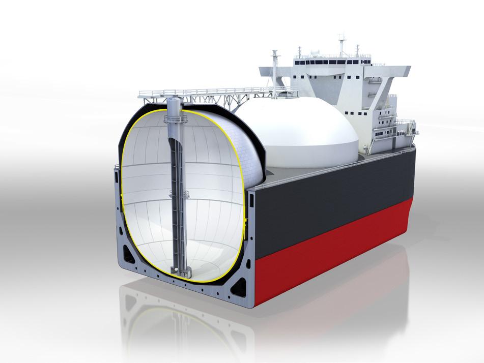
Membrane tanks are integrated in the ship’s hull and are not self-supported as the other IMO Tank types. They have a tight primary membrane welded directly onto the first line of insulation, called the inter-barrier space (I.B.S.), then they require a complete secondary barrier which is supported by the second line of insulation, the insulation space (I.S.) which is fixed on maintained against the inner hull (Mark III concept).
Due to the cryogenic condition of the LNG, this membrane needs to be designed to compensate for the contractions. This is achieved by either using a material with low contraction/expansion characteristics (36% nickel steel), or by creating corrugations which will allow contraction/expansion of the membrane while staying in the elastic domain.
Gaztransport and Technigaz were two distinct companies providing membrane tank systems for the LNG marine transportation, respectively Mark I System and NO82 system. The first LNG carrier designed by Technigaz was delivered in 1964 and the first vessel developed by Gaztransport followed in 1969. In 1994, they decided to merge to form GTT and
improved both systems, which subsequently became the standard for large scale LNG CCS.
The current NO96 concept evolved from the NO82 with an identical primary and secondary barrier made of 0.7 mm thick Invar®, for ‘Invariable’ steel. The insulation is assembled from standard plywood boxes filled with Perlite, a volcanic roc (powder) recognised for its insulation properties. The latest versions of this system (L03, LO3+, SUPER+) now incorporate polyurethane foam insulation panels to improve boil-off performance, the best of which is now a guaranteed 0.085% of volume per day for a standard 174 000 vessel.
The Mark III concept is composed of a 1.2 mm primary corrugated stainless-steel membrane, which will contract and expand 3 mm/m at -163˚C, but this will be compensated by the small and large corrugations. Prefabricated insulations panels, polyurethane foam with fibreglass intertwined, form the I.S. and I.B.S. together, while the secondary barrier is made of Triplex, a tight aluminium foil glued sandwiched between glass clothes. By changing the thickness of the insulation, the boil-off is adjusted to the needs (Mark III Flex and Flex+). Mark III Flex offers a guaranteed boil-off of 0.085% of tank volume per day. Mark III Flex+ offers 0.07% for a standard 174 000 vessel.
The latest evolution, under final development, is the GTT Next1 and can be described as a combination of both systems; the Mark III system with an Invar secondary barrier. All these systems can be combined with the idea of having three tanks instead of four for the same standard volume (174 km3), therefore saving a cofferdam, a pump tower and associated piping.
Vessel designers, builders, and containment system suppliers continue to innovate to support the demand for LNG transport at sizes from small scale to increasingly large.
With the demand for cleaner fuels set to grow – both as a domestic/industrial fuel and as a marine fuel, this evolution will continue.
With global and shipping sector emissions regulations set to tighten further, LNG handling, transport and storage will continue to attract attention as containment system providers look to further refine technology and provide systems capable of meeting future requirements.
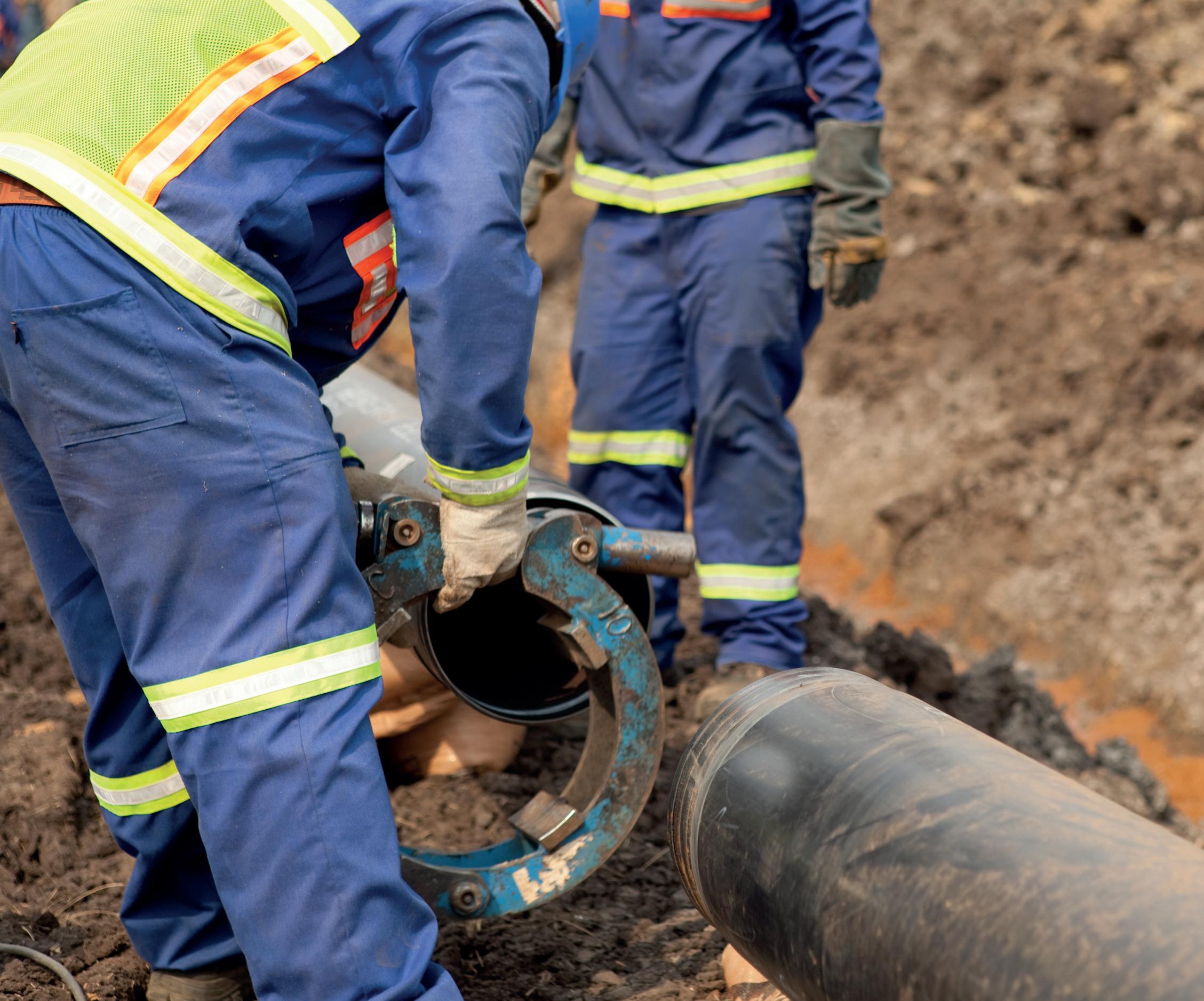

For months now, the European energy sector has been immersed in a paradigm shift. Before the conflict between Russia and Ukraine there was an important dependence on Russian gas, with contributions reaching approximately 45% of supply, and amounting to more than 160 billion m3/yr. The necessity to maintain the supply without Russian energy source has led many countries to look for different kinds of alternatives.
While some countries decided to boost coal-fired thermal power plants back to levels similar to those of 2018, others decided to return to nuclear power plants. This involved heavy investing in the creation of new infrastructure, and halting
plans to dismantle some of the plants whose lifecycles were nearing their end. Such plans are not always environmentally sustainable, and contradict pan-European initiatives to reduce greenhouse gas emissions to net zero by 2030.


Against these trends, there has been significant growth in demand for LNG across Europe over the past year. For example, it is estimated that approximately 18 million households in the UK rely on natural gas, which is also responsible for approximately 40% of all electricity consumed in the country.
There are several reasons for this: it is an easily transportable gas which, once cooled to -160˚C, changes its
Andrew Winter, Sarens, UK, explores the logistics surrounding the LNG industry and its significance in sustaining the European energy system.
state to liquid, and its volume is reduced by up to 600 times. This allows large quantities to be transported more economically and over long distances, without having to worry about possible corrosion of transportation tanks, as is the case with other gases.
The ease of transportation means that it is unnecessary to restrict its transport to the usual pipelines, and it can be obtained from a variety of sources anywhere in the world, thus helping to reduce dependence on a single source. Once transported in special vessels equipped with a double hull to ensure the safety of the process, this gas is pumped from the quay to the terminal’s storage tanks, keeping the temperature stable at -160˚C during the entire process. This is an important logistical challenge that takes approximately 24 hours.
The building and transporting of these storage tanks to their final destination is the most important part of this process. These tanks are supported by special infrastructures that prevent any type of leakage that could jeopardise the integrity of the plant. Thus, the tanks have a double containment: one that contains the liquid at pressure and low temperature, and another one outside that provides greater insulation and protection against any possible impact or degradation caused by the external climate. To guarantee that it is watertight, the inner tank is made of a special nickel alloy, designed to withstand the low temperatures, while the outer shell is made of pre-stressed concrete, further reinforced with more concrete at the base and on the roof.
While finding the right supplier for the purchase of gas is essential to guarantee the whole sector efficiency, it is also essential to ensure that the process of transporting and installing the infrastructures (in which the gas will be stored and processed) is carried out under the required safety conditions and with the highest quality standards.
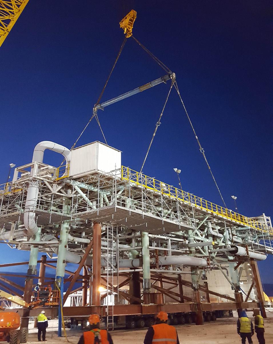
It is important to raise that each of the tanks can have, on average, a height of around 50 m, diameters of around 6 m and weights of around 250 t. In the case of the pre-assembled racks (PAR) or pre-assembled units (PAU) modules that also make up the plants, this weight can be multiplied by almost 20 times, as some units exceed 4900 t.
The size and weight of the infrastructure being transported means that any movement must be done only by specialised companies, with the necessary equipment and staff to accompany the installation from the time of its initial conception to the actual installation at the chosen location.
These transportation and installation processes are not particularly straightforward. In many cases, the tanks must travel hundreds of kilometres from the factory where they are assembled to their place of use. This outstanding duty can be only carried out by really specialised companies, such as Sarens, which first must use cutting-edge cranes with a load capacity of hundreds of tonnes to lift the cargo onto the self propelled modular transports (SPMTs): devices with multiple axle lines that can be driven by an operator via remote control to take the cargo to its next destination.
In many cases, the cargo travels to its destination on large barges or vessels. In this regard, Sarens owns up to eight models of barges that allow these jobs to be carried out with the maximum guarantees. Once the infrastructure is on the quay, it is time to lift it again by a crane and deposit it on this maritime or river transport. It is very often necessary to secure the ground on which the lifting crane is to be placed, either to distribute the weight as well as not provoking permanent damage to the port infrastructure, or moreover to always guarantee the stability of the crane.
Once in the port of destination, the operation is carried out in reverse. That is, a crane – for example, a CC6800, capable of lifting loads of up to 1350 t – unloads each of the tanks or modules onto the SPMTs and transports them to the location where the storage plant will be installed. Due to the weight and size of the convoys, this is a high-precision manoeuvre that requires significant prior planning and,
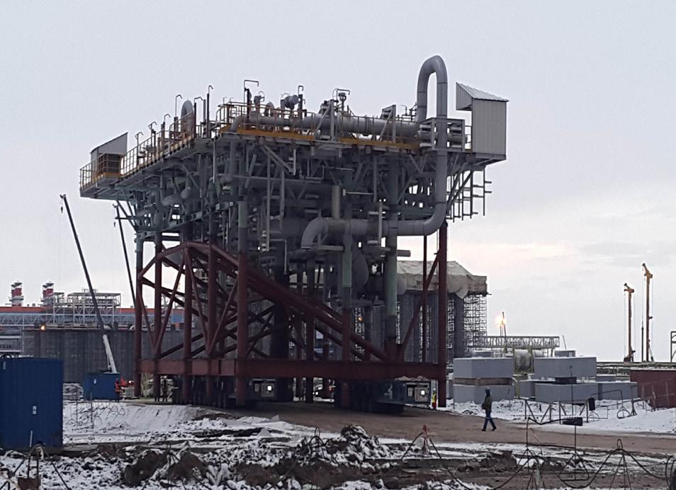
in many occasions, parallel civil engineering works –remodelling of roundabouts, reconstruction of kerbs – to adapt the route to the load being transported.
The work of installing the tanks and modules, which completes the entire logistics operation, also requires coordinated work, especially in infrastructures that are already operational, to minimise the time required and reduce the risks involved in lifting loads of hundreds of tonnes in controlled environments. For this reason, these operations are generally carried out at night in order to minimise risks, and to cause as little damage as possible to the work being carried out in the surrounding area.
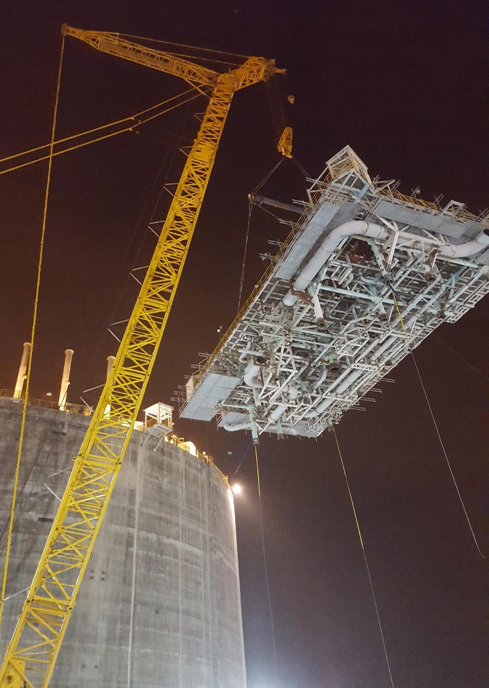
Although the tasks of installing infrastructure at LNG storage and regasification plants are vital, maintenance is equally important to ensure maximum availability of the gas for both industrial use and power generation.
Spain is currently the leader in Europe for the increase in LNG use, with eight regasification terminals. In the case of the UK – one of the countries in Europe that has boosted the use of LNG in recent years – there are only three.
Grain LNG, located in Rochester, is the largest terminal in Europe and the eighth largest in the world, boasting around 600 ha. of surface area and is capable of supplying 20% of the needs of the region’s energy system.
Dragon LNG in Milford Havens, is capable of processing around 9 billion m 3/yr, which is equivalent to 10% of all British consumption. The last one is South Hook LNG, which is responsible for covering 25% of British needs, with approximately 19 billion m 3/yr.
In this regard, it is worth asking whether the growth in LNG demand should be accompanied by an expansion of the gas infrastructure so that it can more easily withstand the increased stress it is under in this context. It could also be advisable to increase the frequency with which preventive maintenance is carried out, as opposed to the corrective measures carried out in the event that errors are detected, in order to keep regasification capacity stable. Sarens has more than 60 years of experience in heavy lifting, engineered transport, and crane rental services and the company believes that it can be of assistance in supporting the European energy grid.
Over the last few years, Sarens has been involved in many projects for the installation and maintenance of LNG process infrastructures around the world. Some examples include:
� The works carried out together with Qatar Fabrication Company (QFAB) for the construction of offshore jackets for Qatar Gas.
� With Chevron for the transport of jackets of more than 2200 t by barges in the Sanha Project in Angola.
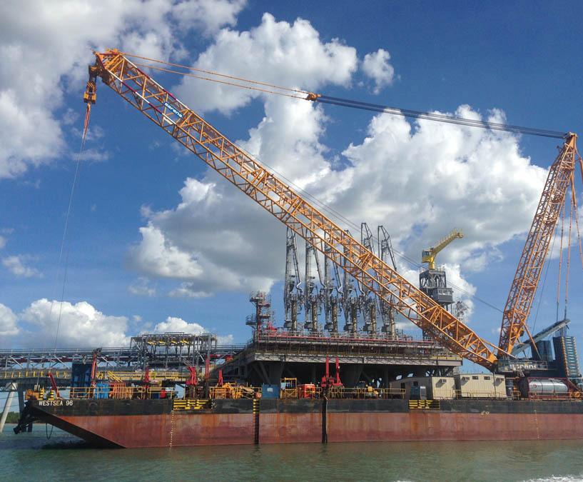
In all cases, these projects of transcendence for the societies in which they are developed, that not only have an impact from the energy point of view, but also generate local employment and improve the economic and social conditions of the environment.
The global energy sector, not only in Europe, is at a particularly decisive moment in its history. It is time to bet on new energy sources such as LNG, and to accompany this bet with the construction of new plants and to reinforce the maintenance of the existing ones in order not to endanger the consistency of the grid. Sarens will continue to support the energy sector as a strategic partner in its heavy lifting, engineered transport and crane rental services.