
July 2023
COMPRESSORS TO TARGET THE ENERGY TRANSITION
TRI-TOP FOR LNG APPLICATIONS
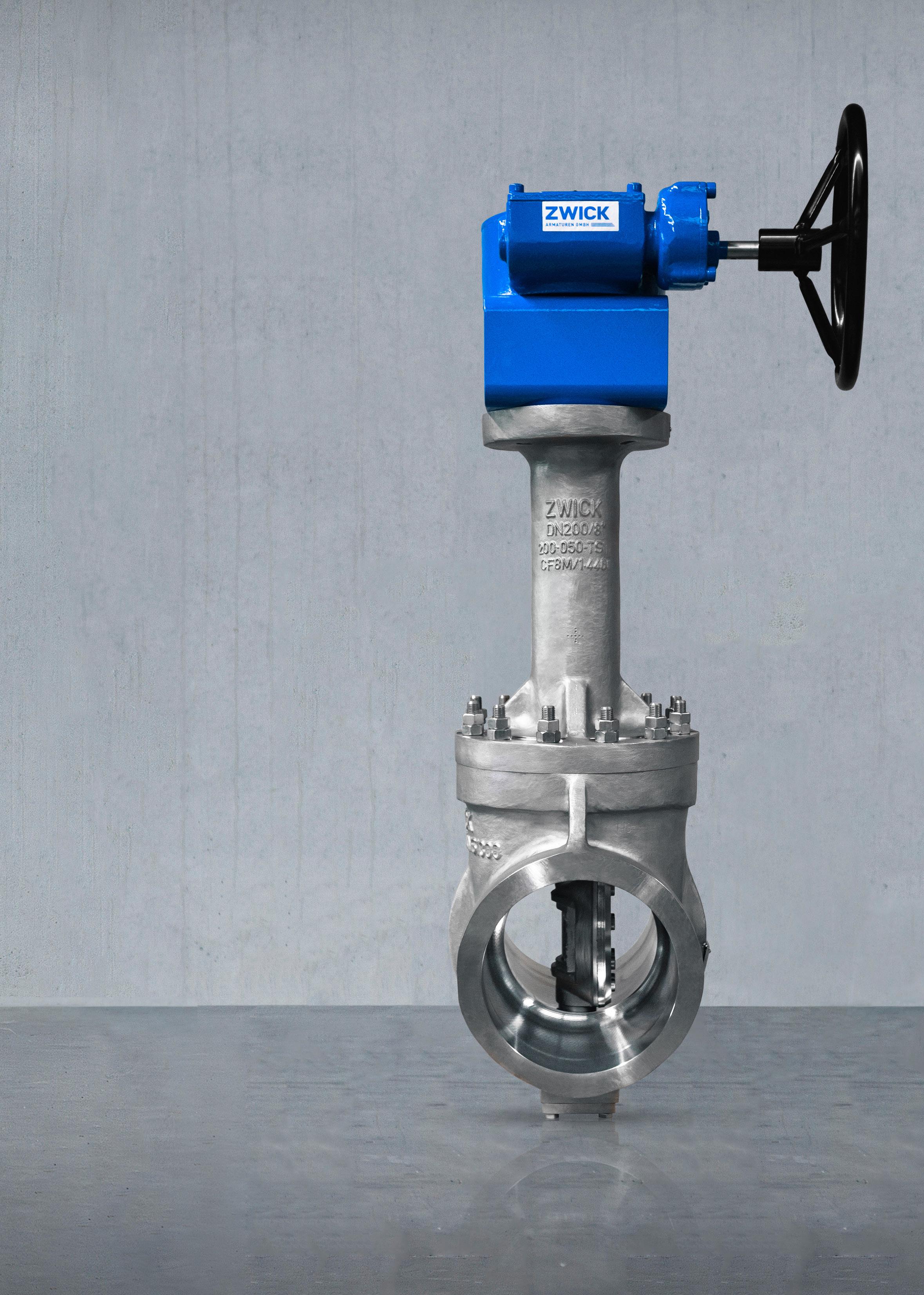
WWW.ZWICK-ARMATUREN.DE
10 Analysing trends in the Asia Pacific

JULY
34 Compressors to target the energy transition
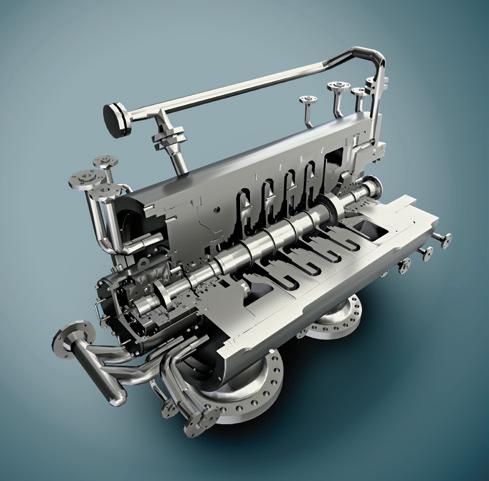
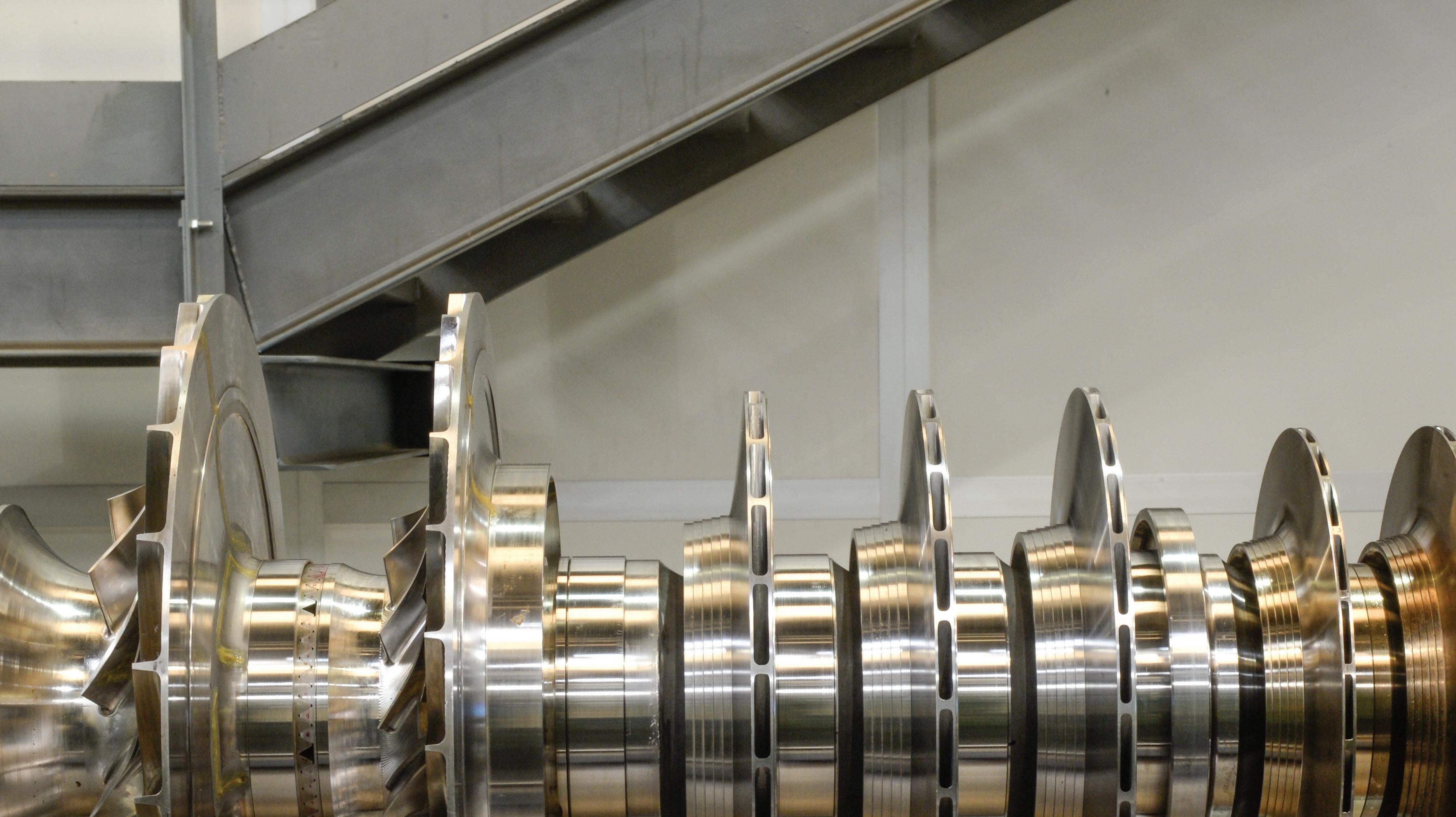
Takashi Niiyama, Mitsubishi Heavy Industries Compressor Corporation, Japan, looks at how compressor solutions for LNG can help the industry navigate the energy transition.
39 Banishing biofouling during outfitting
Catherine Austin, I-Tech, Sweden, explains how to tackle the problem of barnacle biofouling for both the LNG-powered fleet and LNG carriers.
42 Counteracting LNG carrier challenges with marine coatings
LNG carrier fleet must implement energy efficiency measures to meet global and regional regulations, says Ariana Psomas, PPG Segment Director, Protective and Marine Coatings.
46 Meeting the gas heater and vaporiser needs of tomorrow, today
Jeff Awe, Cast Aluminum Solutions, USA, provides insight into the efficient heating and vaporising of natural gas and other process media.
51 More than a pipe dream
Dr Jonathan Wilkins, Enoflex Ltd, UK, details the development journey for a non-metallic, cryogenic pipe technology for use in regasification terminals.
55 Making regasification technology flexible
ECOnnect Energy examine how LNG regasification technology is evolving to meet the needs of today’s energy market.
and Dr Annemarie Ott Weist, Air Products, explore how to prevent unpleasant surprises during mixed refrigerant condensation.
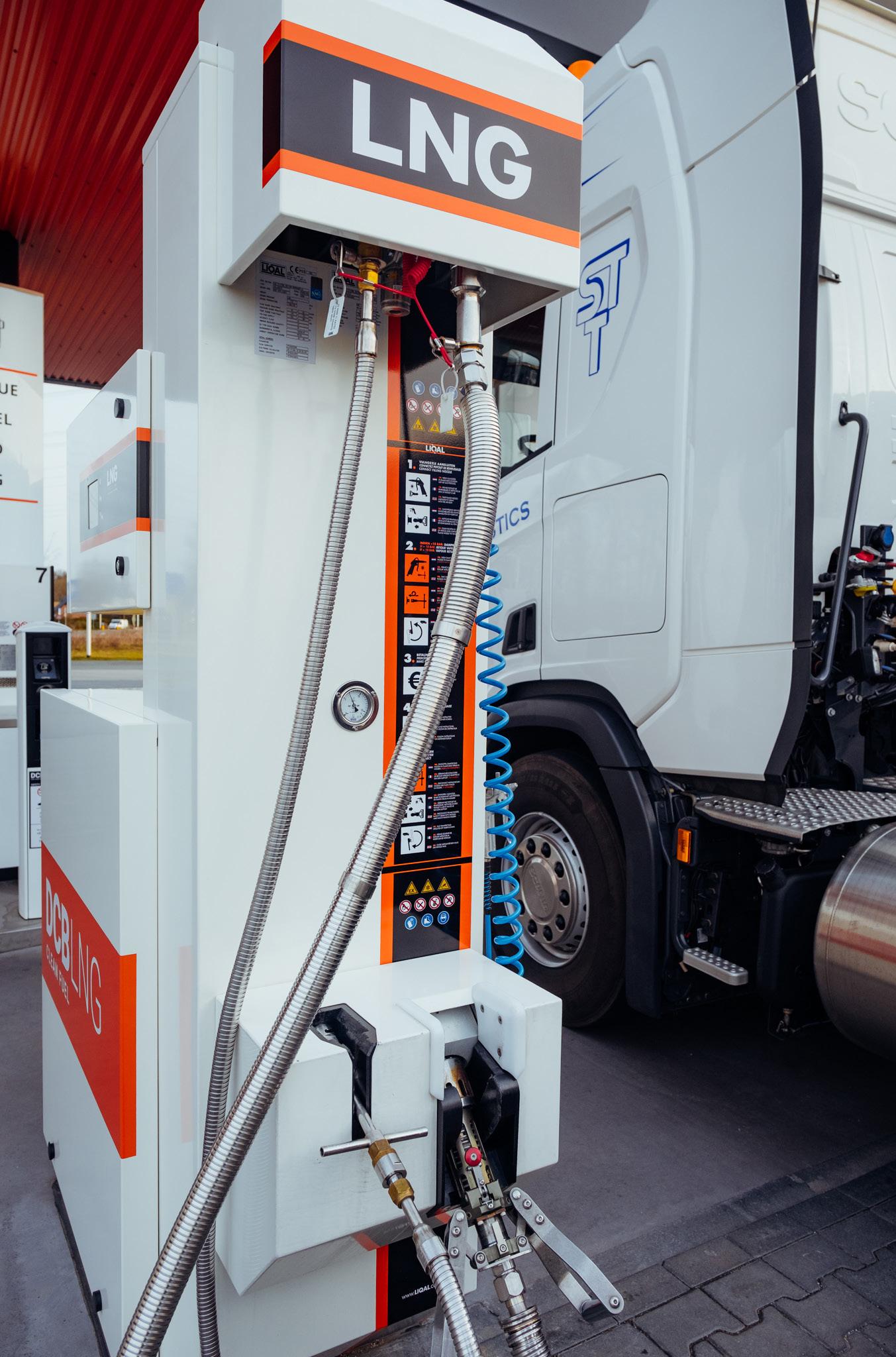
19 A clean fuel to rule the truckstop forecourt
Dover Fueling Solutions, Europe, consider the benefits of using LNG as an alternative fuel.
22 A bridge to alternative fuels
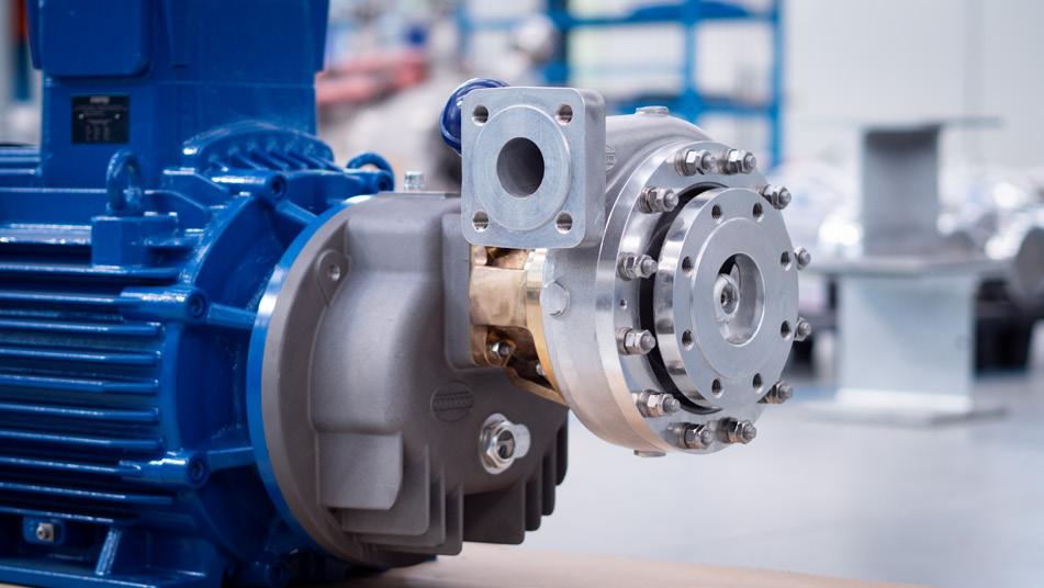
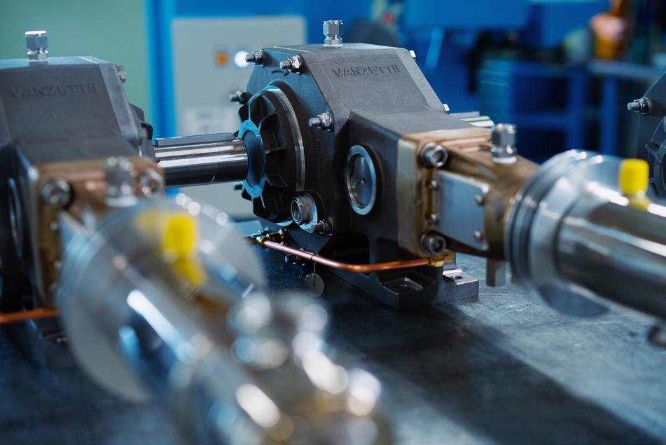
Stefano Calandri, Vanzetti Engineering, Italy, describes how pumps can be used to help the LNG market transition to a cleaner future.
25 Compressors Q&A
LNG Industry asked several companies to discuss some key topics regarding compressors in the LNG industry.
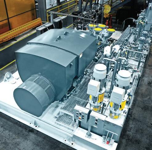
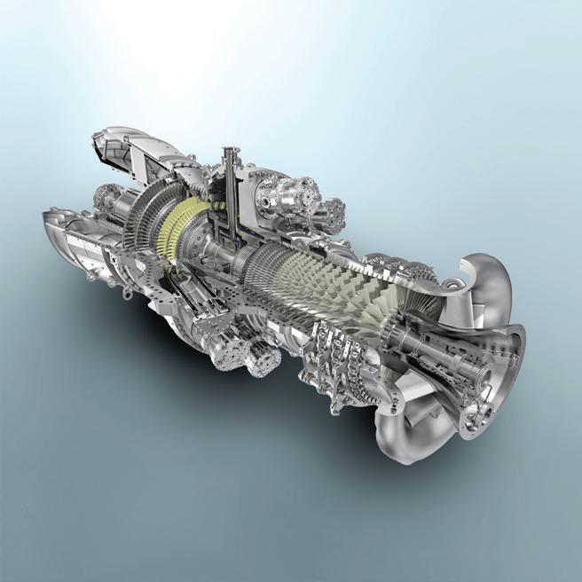
Mitsubishi Heavy Industries Compressor Corporation (MCO) is a global provider of refrigeration compressors, specialising in LNG projects. MCO aims to improve plant efficiency, reduce costs, and address market demands for shorter construction times and lower carbon emissions. Its main compressors, powered by a 120 MW gas turbine, offer variable speed operation and cost-effective startup. MCO ensures system reliability through load string tests and utilises the modular Mitsubishi Compressor Smart Packaging (MCSP) scheme to minimise on-site work and labour expenses. Additionally, the company's Hybrid Combined Cycle (HCC) LNG concept enhances thermal efficiency, capacity and reduces carbon intensity.
ISSN 1747-1826 CONTENTS ON THIS MONTH’S COVER LNG Industry is audited by the Audit Bureau of Circulations (ABC). An audit certificate is available on request from our sales department. CBP006075
2023 03 Comment 05 LNG news
15 Avoiding unpleasant surprises
Roberts, Katherine Wells,
Mark
Bringing clean energy from Texas to power the world.
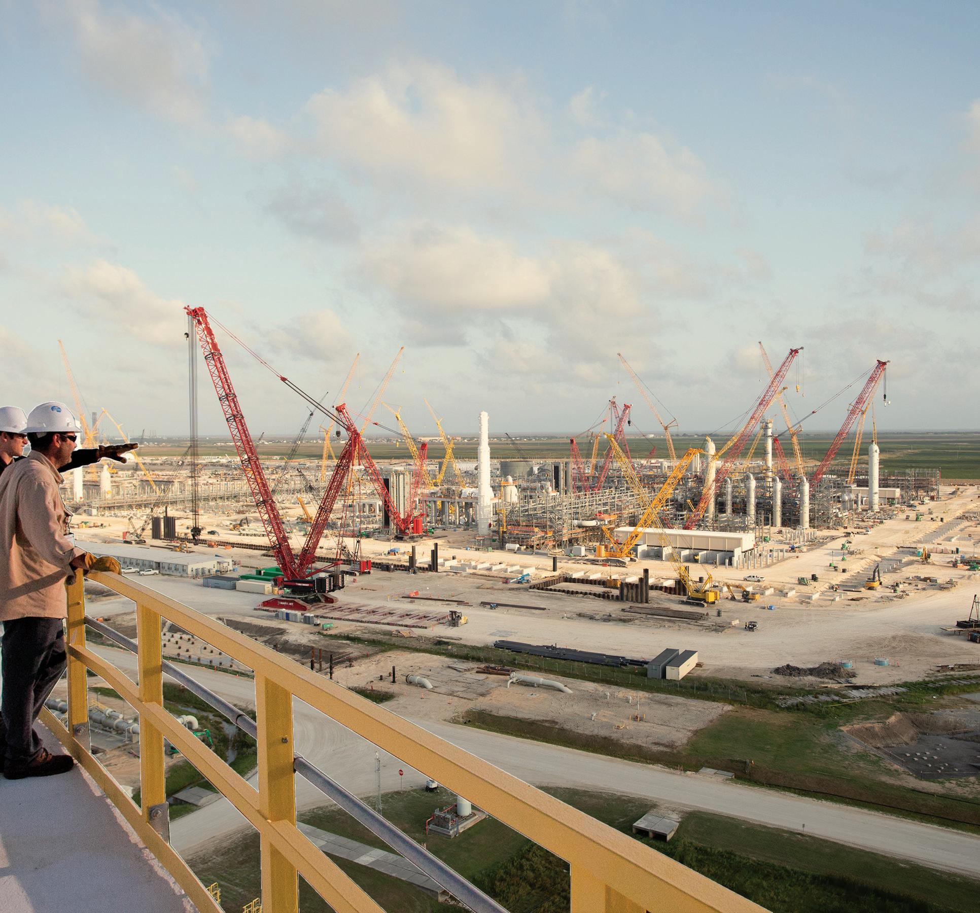
GoldenPassLNG.com
JESSICA CASEY DEPUTY EDITOR

COMMENT
We’ve made it to July, and this can only mean one thing: sports. On offer this year is the FIFA Women’s World Cup 2023. Ahead of the tournament, which is going to be co-hosted by Australia and New Zealand, the World Cup is forecast to reach 2 billion viewers worldwide – nearly one-quarter of the population. This would represent an increase of approximately 79% on the 2019 tournament,1 which was watched by more than 1.12 billion people.2
The matches will be taking place in various stadiums across Australia and New Zealand. In Australia, these matches are spread out across Brisbane (Queensland), Adelaide (South Australia [SA]), Melbourne (Victoria), Perth (Western Australia), and Sydney (New South Wales).
Despite recently being overtaken by the US and Qatar as the world’s largest LNG exporter, Australia is still one of the top exporters of LNG. It is geographically well positioned to serve Asia in its quest to reduce its reliance on fossil fuels, and replace this with LNG. In 2022, Australia supplied 40% of its LNG exports to Japan, 15% to South Korea, 10% to Taiwan, 3% to Singapore, and 2% to both Malaysia and Thailand.3
There is also a fair amount of recent news being released in relation to Australian LNG. A joint study by South Australian LNG import terminal developer, Venice Energy, and SEA Gas, the owners of a 680 km pipeline between Victoria and SA, has confirmed that the pipeline can be reconfigured to facilitate bi-directional flow between the states. As a result, the proposed LNG terminal in the Outer Harbor at Port Adelaide will ensure that both states can secure their gas supplies, particularly during the peak winter period.4
Elsewhere in Australia, Tamboran Resources Ltd has been awarded exclusivity by the Northern Territory government for over 170 ha. on the Middle Arm sustainable development precinct for a proposed LNG development,
Northern Territory LNG (NTLNG). The site is expected to host an LNG development with an initial capacity of 6.6 million tpy, with first production targeted by 2030.5
Not long after this announcement, it was declared that Tamboran has signed two memorandum of understandings with BP Singapore Pte. Limited and Shell Eastern Trading (Pte) Ltd for each company to purchase up to 2.2 million tpy from the proposed NTLNG project over a 20-year period, which Tamboran’s CEO, Joel Riddle, believes further emphasises the importance of LNG demand growth in the Asia Pacific region.6
For more on the Asia Pacific region, make sure to read Charles River Associates’ regional report which looks at key trends in the Asia Pacific LNG market, and considers how relevant global developments are affecting the region.
References
1. ‘Total television audience of the FIFA Women’s World Cup in 2019, with a forecast for 2023’, Statista, (5 June 2023), www.statista.com/ statistics/1386733/womens-world-cup-total-tv-viewership/
2. ‘2019 world cup watched by more than 1.12 billion’, FIFA, (18 October 2019), www.fifa.com/tournaments/womens/ womensworldcup/france2019/news/fifa-women-s-world-cup2019tm-watched-by-more-than-1-billion
3. ‘Australia’s 2022 LNG exports, by country’, Wood Mackenzie Lens Gas & LNG, www.woodmac.com/news/opinion/japan-australianlng-exports/
4. ‘SA LNG Import Terminal can serve the east coast – study confirms’, Venice Energy, (4 May 2023), https://veniceenergy.com/ wp-content/uploads/2023/05/Media-Release-Pipeline-Study230504-WEB.pdf
5. ‘Tamboran secures land at Middle Arm Sustainable Development Precinct for proposed Northern Territory LNG (NTLNG) Development’, Tamboran Resources, (9 June 2023), www.investi.com.au/api/announcements/tbn/c2224152-5fb.pdf
6. ‘Tamboran signs two MOUs with bp and Shell for supply of 4.4 MTPA of LNG from the Company’s proposed NTLNG development’, Tamboran Resources, (23 June 2023), www.investi.com.au/api/announcements/tbn/23dcafe8-1f9.pdf
Managing Editor James Little james.little@palladianpublications.com
Senior Editor Elizabeth Corner elizabeth.corner@palladianpublications.com
Deputy Editor Jessica Casey jessica.casey@palladianpublications.com
Editorial Assistant
Théodore Reed-Martin theodore.reedmartin@palladianpublications.com
Sales Director Rod Hardy rod.hardy@palladianpublications.com
Sales Manager Will Powell will.powell@palladianpublications.com
Production Manager Calli Fabian calli.fabian@palladianpublications.com
Digital Events Manager
Louise Cameron louise.cameron@palladianpublications.com
Digital Events Coordinator Stirling Viljoen stirling.viljoen@palladianpublications.com
Digital Administrator
Leah Jones leah.jones@palladianpublications.com
Digital Content Assistant Merili Jurivete merili.jurivete@palladianpublications.com
Administration Manager Laura White laura.white@palladianpublications.com
Editorial/Advertisement Offices, Palladian Publications Ltd 15 South Street, Farnham, Surrey, GU9 7QU, UK Tel: +44 (0) 1252 718 999 Website: www.lngindustry.com
LNG Industry Subscription rates: Annual subscription: £50 UK including postage £60 overseas (postage airmail) Two year discounted rate: £80 UK including postage £96 overseas (postage airmail) Subscription claims: Claims for non receipt of issues must be made within 3 months of publication of the issue or they will not be honoured without charge. Applicable only to USA & Canada. LNG Industry (ISSN No: 1747-1826, USPS No: 006-760) is published monthly by Palladian Publications Ltd, GBR and distributed in the USA by Asendia USA, 17B S Middlesex Ave, Monroe NJ 08831. Periodicals postage paid New Brunswick, NJ and additional mailing offices. POSTMASTER: send address changes to LNG Industry, 701C Ashland Ave, Folcroft PA 19032.
CryoMac® 4 LNG Fueling Nozzle
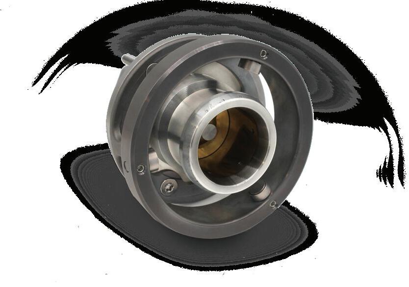

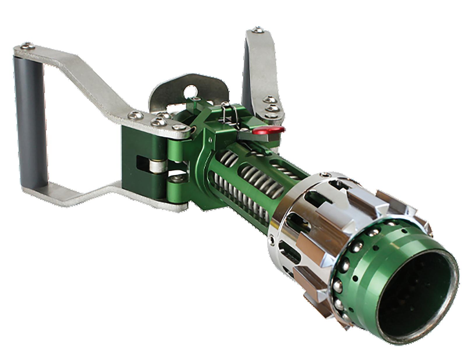

Maximum safety for LNG fuel technology

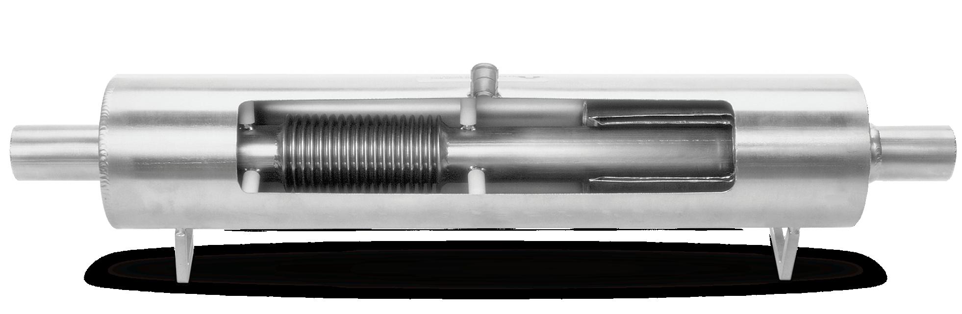
Vacuum Jacketed Pipe (VJP)
The most cost-effective way to transfer cryogenic liquids
SAFE
“Safety Stop” for added safety and operator protection.


Stainless Steel Inner Pipe
these advanced features to produce exceptional efficiencies across the
Evacuation & Safety Device
Super-Insulation
www.regoproducts.com www.acmecryo.com
entire system.
The inner and outer pipe is constructed of 300 series stainless steel. Insulation is a low vacuum with multiple layer insulation (MLI).
The comprehensive component design to complete the system design, manufacture, and installation capability.
Cryogenic insulation for Nitrogen, Oxygen, Argon, Helium, Natural Gas, Carbon Dioxide, Hydrogen
Patented nozzle safety feature is recognized in the market as a major failsafe advantage for the operator.
DURABILITY þ Copyright © 2023 OPW Clean Energy Solutions
Ball cage interface with receptacle adapter ring guides and locks the nozzle in place for optimum engagement and user interface to increase environmental seal life.
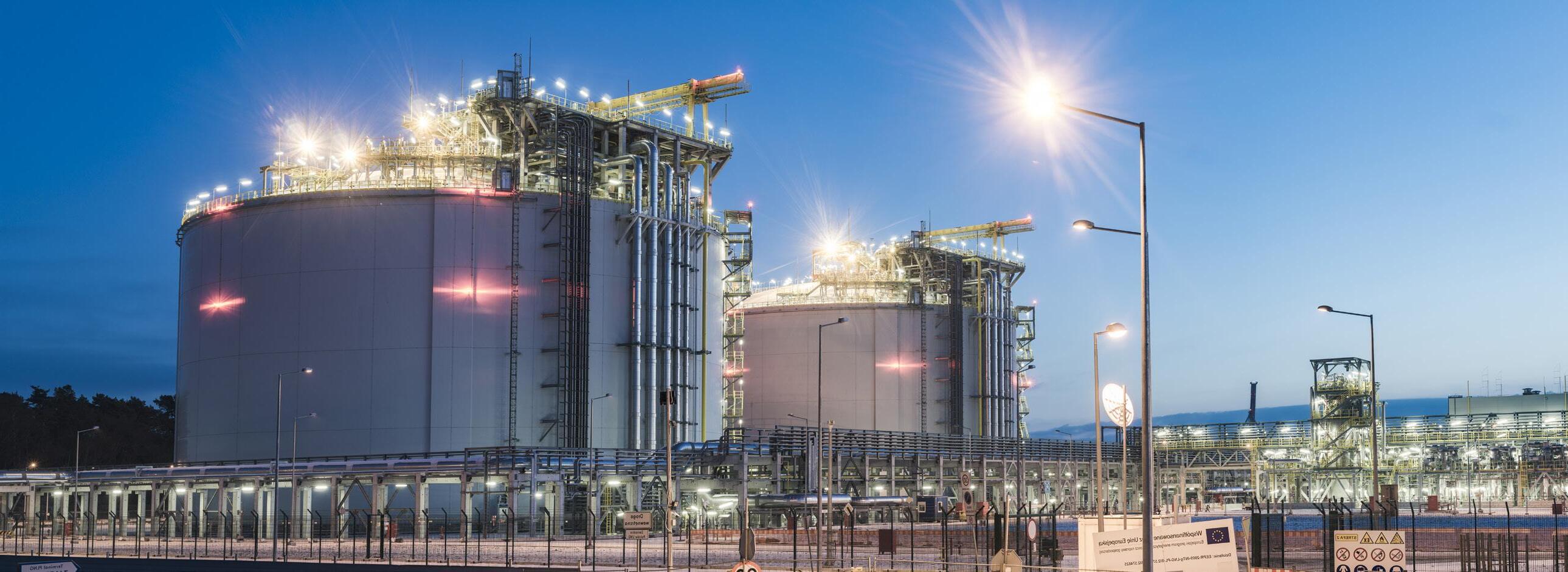
the Philippines First Gen welcomes BW Batangas FSRU in the Philippines
First Gen Corporation has welcomed the arrival of the BW Batangas, in Batangas Bay. The BW Batangas is a FSRU that was chartered by its wholly-owned subsidiary, FGEN LNG Corporation, as part of its interim offshore LNG terminal project.
FGEN LNG and BW LNG, a wholly owned subsidiary of the BW Group, the world's largest gas shipping company, entered into a charter agreement in respect of the BW Batangas in April 2021 to play a pivotal role in securing the country’s energy supply through its capabilities to store and regasify imported LNG to fuel the natural gas power plants located at the First Gen Clean Energy Complex (FGCEC) in Batangas.
The BW Batangas, which was previously identified as the BW Paris, can store 162 524 m3 of LNG and regasify up to 500 million ft3/d of gas to enable LNG to be utilised to supplement the depletion of natural gas reserves from Malampaya.
First Gen chose to rename its FSRU as the BW Batangas because of the Lopez-led company’s desire to acknowledge the consistent support of the Province of Batangas, Batangas City, and the local government units that host the FGCEC where it will be based. First Gen’s decisions to charter the BW Batangas and to construct its LNG terminal project underscore the company’s commitment to supporting the energy security of the Philippines.
Singapore
LNGNEWS
Vietnam
T&T Group to develop LNG and hydrogen projects with Korean companies
T&T Group and Korean partners recently signed and awarded a memorandum of understanding to develop LNG and hydrogen projects in Vietnam.
Specifically, T&T Group and Korea Gas Corporation (KOGAS) will co-operate to develop LNG gas power projects in Vietnam, and convert coal power projects already in the Power Plan VIII to gas power. The two sides will also explore opportunities to participate in hydrogen production projects to meet the high potential demand of power projects in commercial operation. Other power projects will be developed and built and operate in the near future, in line with the orientation and long-term strategy of the Government of Vietnam in the recently approved Power Master Plan VIII.
T&T Group and KOGAS will jointly develop projects using LNG refrigeration from LNG terminals in Vietnam and operate a LNG cold chain business nation-wide; they will also engage in other business activities related to LNG (procurement, importation, transportation, and supply of LNG for power generation and other industrial purposes).
T&T Energy, a member of T&T Group, and SK E&S, an energy company of SK Group (Korea), have also signed a memorandum of understanding on co-operation in the LNG power sector.
Accordingly, T&T Energy and SK E&S will co-operate to develop LNG terminals and gas power plants in accordance with Vietnam's development orientation and legal regulations. Under the agreement, SK E&S will be the unit responsible for finding financial resources to support the project implementation.
Eastern Pacific Shipping celebrates 100th LNG bunkering operation
Eastern Pacific Shipping (EPS) has reached a new milestone for its dual-fuel fleet following the successful 100th LNG bunkering operation in Singapore for its managed 210 000 DWT newcastlemax, M/V Mount Tai
FueLNG, a joint venture between Seatrium Offshore & Marine and Shell Singapore, deployed its latest LNG bunker vessel, FueLNG Venosa, to provide M/V Mount Tai with 4887 m3 of LNG.
This is the first bunkering operation for FueLNG Venosa,
which has a total capacity of 18 000 m3 and is able to simultaneously carry out cargo handling and bunkering operations.
M/V Mount Tai, which is chartered on consecutive voyages with BHP, is equipped with M-type, electronically controlled gas injection two-stroke engines that have negligible levels of methane slip. M/V Mount Tai will be a part of EPS’ low carbon emission fleet, transporting iron ore along the green corridor from West Australia to Northeast Asia.
July 2023 5
USA
Equinor signs long-term LNG purchase agreement with Cheniere
Equinor and Cheniere have announced a new 15-year sales and purchase agreement (SPA). This agreement brings the total volumes that Equinor has contracted with Cheniere up to around 3.5 million tpy.
This new SPA with Cheniere will double the volumes of LNG that Equinor will export out of Cheniere’s LNG terminals on the US Gulf coast.
The LNG market is expected to grow significantly because of the role it will play in providing energy security, as well as enabling a transition to a cleaner energy mix in many markets. With more US LNG in its portfolio, Equinor will increase its role as a supplier of natural gas in global markets while maintaining its position as the major supplier of natural gas to Europe.
Under the SPA, Equinor has agreed to purchase approximately 1.75 million tpy of LNG from Cheniere Marketing on a free-on-board basis, for a term of approximately 15 years from the start of the delivery of the total amount of LNG volumes. The deliveries under the SPA will start in 2027 and is expected to reach the full 1.75 million tpy towards the end of this decade.
Australia
Tamboran secures land for LNG development project
Tamboran Resources Ltd, an Australian independent gas company, has secured 170 ha. of land on the Middle Arm sustainable development precinct, near Darwin, for its proposed Northern Territory LNG development (NTLNG).
NTLNG represents the first fully-integrated LNG development in Northern Australia where upstream, midstream, and downstream production and processing are based in the Northern Territory. The site is expected to host an LNG development with an initial capacity of 6.6 million tpy of LNG, with a potential for expansion, dependent on the completion of the concept select study, successful Beetaloo appraisal drilling and flow testing, and government approvals.
Tamboran is aiming to start LNG production by 2030. FEED studies remain ongoing for the proposed 100 million ft3/d domestic pilot development, with volumes contracted to Origin Energy for 10 years.
Colombia SPEC LNG terminal receives LNG delivery
More than 130 000 m3 of LNG, purchased by the main thermal generators in the country as a provision to deal with the El Niño phenomenon in 2H23, has arrived at the SPEC LNG regasification terminal.
This LNG is stored at the Cartagena regasification terminal to be transformed from a liquid to a gaseous state and delivered, when required, to the main thermal plants in the country in order to support the generation of electricity during the period of low hydrology.
In the scheme that supports the generation of electrical energy defined by the Energy and Gas Regulation Commission (CREG), the SPEC LNG regasification terminal has the role of infrastructure agent that provides its services to three thermal generators in the country, which acquire backup LNG through the Marketing Agent that represents them.
The regasification terminal was vital in 2020, when the level of the reservoirs reached 30%, it regasified close to 13 000 million ft3 of LNG for more than 200 days for the thermal plants and received 16 methane tankers throughout the year. In this way, gas-fired thermal generation contributed close to 22% of the national energy demand and a possible shortage of electrical energy was avoided.
THE LNG ROUNDUP

6 July 2023
us on LinkedIn to read more about the articles www.linkedin.com/showcase/lngindustry
Wärtsilä to extend regasification capacity for Croatian LNG terminal
Angola LNG loads project’s 400th LNG cargo
National Grid Grain LNG celebrates utilisation
Follow
X
X
X
LNGNEWS
Turboexpanders are NEAT
Nikkiso Clean Energy & Industrial Gases
Turboexpanders are NEAT – Nikkiso Expander Application Technology (NEAT). Our turboexpander team has been designing and engineering turboexpanders for more than 200 (combined) years! We stand ready to help with most any turboexpander need, and support for the hydrocarbon gas processing, petrochemical and hydrogen industries. And our turboexpander performance can be tailored to plant operating demands and to reduce operating costs.
We provide Turboexpander-Compressors; energy storage systems; liquid air, carbon dioxide, liquid hydrogen solutions; pressure letdown energy recovery systems and Organic Rankine Cycle systems for geothermal and waste heat applications. To support all these, we offer global aftermarket service and support.
Want to know more? Ask Nikkiso.
Find out more at
or email us at NEATsales@NikkisoCEIG.com Process Systems – Heat Exchanger Systems Cryogenic Pumps – Service – Solutions
www.NikkisoCEIG.com
LNGNEWS
Germany
10 – 13 July 2023
LNG2023

Vancouver, Canada www.lng2023.org
05 – 08 September 2023
Gastech Singapore www.gastechevent.com
05 – 08 September 2023
Offshore Europe
Aberdeen, Scotland
www.offshore-europe.co.uk/en-gb.html
25 – 28 September 2023
Turbomachinery and Pump
Symposia 2023
Texas, USA https://tps.tamu.edu
02 – 05 October 2023
ADIPEC 2023
Abu Dhabi, UAE www.adipec.com
31 October – 03 November 2023
Americas Energy Summit & Exhibition 2023
Louisiana, USA
www.americasenergysummit.com
28 November – 01 December 2023
The 23rd World LNG Summit & Awards
Athens, Greece www.worldlngsummit.com
Alternoil and GrønGas to expand value chain for sustainable fuel alternative
Alternoil GmbH, based in Germany, and biogas plant operator, GrønGas A/S, from Denmark, have signed a long-term and exclusive supply agreement for waste-derived bio-LNG to further increase the availability of Alternoil's renewable fuel, REEFUEL. Together, the companies aim to master the transformation to a climate-friendly transport sector.
Alternoil has set itself the goal of making an important contribution to the decarbonisation of heavy-duty transport. Since the end of 2020, the company has been providing the transport industry with the climate-friendly fuel alternative REEFUEL (bio-LNG and e-LNG) through its nationwide network of filling stations. The 100% renewable fuel is produced from green hydrogen generated by wind energy and biomethane from certified organic waste processes.
Alternoil's exclusive annual purchase of the total production volume of bio-LNG from GrønGas will further increase the availability of REEFUEL throughout Alternoil's filling-station network. According to Alternoil GmbH, this is a scaling measure that is a clear response to the market developments. By using Alternoil's renewable fuel, companies can significantly reduce their carbon dioxide emissions in the transport of heavy goods and thus demonstrably improve their company's carbon footprint.
In the coming years, the purchasing volume of REEFUEL will be further expanded in line with the growth of the market in Germany. Alternoil already provides the renewable fuel alternative through a network of filling stations in Germany. By 2030, Alternoil and its partners plan to achieve climate neutrality for over 50 000 heavy-duty trucks by developing additional waste-to-energy projects.
To save even more carbon dioxide along the value chain in the near future and in response to market developments, Alternoil GmbH is currently participating as a joint venture partner in the construction and operation of the REEFUELERY, one of the world's largest liquefaction plants for biological and synthetic fuels, located in the heart of Germany. The plant is scheduled to commence operations in 2024.
Qatar
QatarEnergy and China strike LNG deal
QatarEnergy has signed definitive agreements with China National Petroleum Corporation (CNPC), covering the long-term supply of LNG to China and a partnership in the North Field East LNG expansion project (NFE).
The two parties signed an LNG sales and purchase agreement (SPA) for the delivery of 4 million tpy of LNG from the NFE project to CNPC’s receiving terminals in China over a span of 27 years, marking the industry’s longest-term SPA commitment.
Pursuant to this agreement, QatarEnergy will transfer to CNPC a 5% interest in the equivalent of one NFE train with a capacity of 8 million tpy. This transfer will see CNPC become a partner in the NFE project and will not affect the participating interests of any of the other shareholders in the project.
The agreements were signed by Saad Sherida Al-Kaabi, the Minister of State for Energy Affairs, the President and CEO of QatarEnergy, and M Dai Houliang, the Chairman of CNPC, during a special ceremony held at QatarEnergy’s headquarters and attended by senior executives from both companies.
8 July 2023
BRIGHTER FUTURE COOLER BY DESIGN ®

Chart’s LNG power generation solutions provide natural gas to hundreds of thousands of homes. This is one way Chart facilitates LNG as a safe, clean-burning fuel for energy, transportation and industry.
Learn more at www.ChartLNG.com LNG@ChartIndustries.com
he volatility in global LNG markets over the previous two years has led to significant shifts and patterns in the sector globally, not least in the Asia Pacific region. Record-high prices in LNG spot markets, driven in part by the Ukraine War and the ensuing global energy crisis, have affected all LNG-importing countries.
Background

Spot LNG prices in Asia, as indicated by the Platts JKM Price Assessment,1 had already begun to increase during 2021. This was in part a result of a cold northern hemisphere winter in 2020/2021,2 resulting in gas storage levels below average across the Asia Pacific region going into the winter of 2021/2022.3 Prices in Europe were also increasing,4 in part due to a reduction of pipeline imports from Russia (even before the Ukraine War5) and other factors, such as weaker wind power.6 The Ukraine War and subsequent further reductions in Russian pipeline gas flowing to Europe significantly exacerbated this situation. Historically, Europe (with the exception of Iberia) acted in part as a balancing market for global LNG, with spot cargos sailing to Europe when the netback price spread vs Asia was positive. This significantly higher European LNG demand has temporarily shifted the balance of LNG importers globally, with substantial impacts on the Asia Pacific region. These impacts are likely to continue manifesting in the short and medium term.
South Asia
Whilst all LNG-importing countries in the Asia Pacific region have been affected to some extent, the spike in spot LNG prices
10
Richard Acklam, Associate Principal, Charles River Associates, highlights the key trends in the Asia Pacific LNG market, whilst touching on relevant global developments to analyse how they are affecting the Asia Pacific region.

11
has had a much more critical effect on some countries than others. South Asia (Pakistan, India, and Bangladesh) has been one of the regions hardest hit by the energy crisis, in no small part stemming from high LNG prices.
In India, as with many Asia Pacific countries, natural gas has been promoted as a transition fuel7 – cleaner than coal for power generation and for use in industrial applications, but also able to mitigate the intermittency of renewables, such as wind
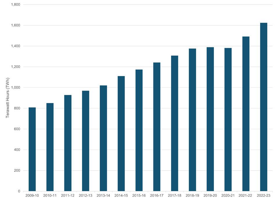
and solar. Furthermore, these are often markets where electricity consumption is rapidly increasing in absolute terms, and natural gas also plays a role in this expansion. Indeed, electricity generation in India has more than doubled since 2010, as shown in Figure 1.8

However, a high level of dependency on imported LNG (which accounts for around 50% of natural gas consumption in India9), coupled with high global gas prices, has decreased the attractiveness of gas as a transition fuel in the power generation sector. Imported LNG cannot currently compete with either coal or renewables in the power generation sector; in the 12 months to March 2023, electricity generated from coal increased by 12.4% y/y, with gas-fired power generation falling by 28.7%.10 This has resulted in a corresponding fall in LNG imports, which were 16.3% lower during 2022 than the previous year, and 21.6% lower than the peak in 2019, as illustrated in Figure 2.
Similarly, Pakistan and Bangladesh have faced significant problems. Neither country has sufficient volumes contracted on a long-term basis to meet demand, so both rely on the spot market. With the increase in spot LNG prices, importing the required volume of the fuel has not been possible, as high-priced gas becomes uncompetitive in downstream sectors. Both countries have suffered from repeated blackouts due to a lack of LNG; Pakistan relies on gas for one-third of its power generation needs.11 Bangladesh is even more reliant with almost three-quarters of its power generated from imported LNG.12 Pakistan is also turning back to coal for its power generation needs, looking to domestic coal. Indeed, Pakistan’s Energy Minister, Khurram Dastgir Khan, recently stated that Pakistan would look to quadruple its domestic coal-fired capacity and would not build any more gas-fired power plants.13 Similar dynamics are seen in Bangladesh, with coal-fired generation favoured over imported LNG.14
From the perspective of the LNG market, there is a risk that persistent high prices will incentivise the South Asia region to skip the wholesale adoption of natural gas as a transition fuel (at least in the power generation sector) and instead either burn more coal, despite the associated negative environmental effects, and/or substantially increase deployment of renewable energy generation technologies as a more economical alternative to natural gas. Whilst gas demand in these countries could still increase over time, a lack of a return to the growth rates seen prior to the COVID-19 pandemic could contribute to an LNG supply-demand imbalance in the latter half of this decade.
China
Whilst Chinese LNG imports also fell in 2022, the reasons for this, and in particular the trends and implications going forward, are very different from the situation in South Asia. LNG imports to China fell by approximately 20% in 2022.15 Natural gas demand fell by approximately 2% in China from 2021 to 2022 – although pandemic lockdowns extended throughout most of 2022, this was similar to the situation in 2021. However, 2022 saw an increase in both domestic gas production (6% y/y16) and pipeline imports (an additional 5 billion m3 from Russia17,18 and 5 – 6 billion m3 from Central Asia17), largely offsetting the reduction in LNG imports.
Natural gas demand in China is expected to rebound to at least 2021 levels this year. However, whether this translates into a rebound in LNG imports in the short term will largely depend on prices in the spot market. JKM prices fell from their historic

12 July 2023
Figure 1. Electricity generation in India, TWh, 2009 – 2023. Data is from April – March for each period.8
Figure 2. LNG imports in India (million t), 2012 – 2022. 2022 spot and short-term data not yet available.9,19
Figure 3. JKM LNG price assessment, US$/million Btu, January 2021 – May 2023. Source: Bloomberg LP, JKL1 COMDTY, accessed 31 May 2023.

highs during the last four months of 2022 (albeit rising slightly in December1), and the downward trend continued into 2023 as the European winter remained mild, reducing that region’s demand for natural gas. If JKM prices continue to fall, or even if they stabilise at a level around US$10 – US$12/million Btu (levels not seen since mid-2021), Chinese importers may return to the spot market.
A different picture is being painted in the long-term LNG market as it pertains to China. Having relied to an increasing extent on the spot market (in 2021, spot and short-term imports accounted for almost 50% of imports19), Chinese companies are now signing large numbers of long-term contracts, with around 20 signed during 2021 alone, accounting for approximately 50% (in volume terms) of all contracts signed that year.20 That pace has been maintained, with further large-volume deals in 2022 and 2023, such as those between QatarEnergy and Sinopec (4 million tpy for 27 years20) and ENN Group’s agreement with Energy Transfer (2.7 million tpy for 20 years21). This drive for Chinese companies to lock in long-term gas contracts is due to several factors. Natural gas demand in China is likely to continue rising, with more LNG required to maintain this. Whilst historically, Chinese companies were willing to rely on the spot market, recent high (and highly volatile) prices seem to be driving importers back to long-term contracts. Finally, security of supply is also a factor – during 2H21, numerous Chinese provinces experienced widespread power outages. As well as affecting people living in these provinces, these blackouts significantly impacted China’s economic activity, with Goldman Sachs estimating as much as 44% of China’s industrial activity being affected.22 Whilst other factors apart from natural gas supplies contributed to this (such as temporary coal shortages and a lack of wind power generation), signing large numbers of long-term LNG contracts generally improves security of supply relative to spot purchases.
Japan and South Korea
The current trend elsewhere in East Asia is somewhat different. Japanese imports only fell by 3.1% in 202223 and rose very slightly in South Korea.24 This led to Japan once again becoming the largest importer, overtaking China. However, based on the recent long-term contracting trends this looks unlikely to be more than a temporary situation.
In contrast to the contracting spree being undertaken by Chinese companies, only two contracts with a duration of five years or more were signed for import to Japan in 2021 (with one of those covering only 0.5 million t in total over five years). Similarly, only one long-term contract was signed for import to South Korea.20
There is also potential in the medium-term for a recovery and increase in nuclear power generation for both Japan and South Korea. Japan has 16 nuclear reactors in the process of acquiring approval to restart post-Fukushima, and the government plans for nuclear to account for at least 20% by 2030, compared to around 6% currently.25 In South Korea, the new government elected last year saw a turnaround in policy, with nuclear power generation expected to slightly increase to account for a minimum of 30% of electricity generation in 2030 (as opposed to the previous policy of phasing out nuclear power completely). These policies could potentially create lower LNG demand in both countries.
However, both Japan and South Korea still have a significant proportion of electricity generated from coal, which may be
replaced first by continuing or growing nuclear generation, supporting demand for LNG. Indeed, recent long-term deals have been signed by Inpex (1 million tpy for 20 years26) and Itochu (1 million tpy for 15 years27), as well as by South Korean importers (albeit for smaller volumes).28,29 Particularly in Japan, in order to avoid long-term LNG imports declining substantially in the next few years, companies will have to sign more long-term contracts or increase reliance on volatile spot markets, as volumes contracted in 2030 are only 70% of those contracted on a long-term basis in 2023.30
Southeast Asia
There are also several countries in Southeast Asia which are new (or expected) entrants to the LNG market, such as Cambodia, the Philippines, and Vietnam. All three had plans for new LNG regasification terminals delayed by the COVID-19 pandemic and related supply chain issues. The Philippine terminal and one of two Vietnamese terminals have, or will shortly, import their first cargos (Cambodia’s project is still ongoing, with a second Vietnamese terminal expected to start operations later this year).31,32 LNG demand in these countries will be driven by both increasing power demand and a transition away from coal, but particularly in Vietnam this may be disrupted by rapid buildout of renewable energy capacity. Vietnam and the Philippines have not as yet been able to secure long-term volumes, bringing both price stability and volume certainty, and as such are reliant on volatile spot markets. If spot prices remain high and/or volatile for the medium-term, a switch (at least partially) from coal to renewables in these markets may occur, dampening the outlook for long-term LNG demand.
Conclusion
The LNG-importing countries of the Asia Pacific market are at various stages in terms of LNG demand development, as reflected in the current trends explored in this article. Existing markets with high growth potential in South Asia have recently been hit by spot LNG prices which render gas too expensive for many applications. Mature markets, such as Japan and South Korea, look to be unwilling to replace long-term contracts at the same previous rate as a result of potential long-term demand concerns. Chinese importers have taken advantage, dominating the long-term contracting market in the previous two years. These trends, in conjunction with high spot prices, have led to doubts about demand in new growth markets in Southeast Asia.
One of the fundamental questions for these markets currently is the direction of spot prices in the short and medium term. Whilst this is, in part, dictated by demand in Europe, another major factor is supply. Significant new capacity is slated to come online from 2025 – 2027, primarily from Qatar and the US. Qatar’s major North Field expansion project will result in additional capacity totalling 49 million tpy, although only 6 million tpy of that is currently contracted.33 Whether or not the additional capacity is eventually sold under long-term contracts (as is expected by Qatar33), importers in the Asia Pacific region look likely to benefit from lower prices in the medium term.
References
A comprehensive list of this article’s references can be found on the LNG Industry website at: www.lngindustry.com/ special-reports
14 July 2023
Dual mixed refrigerant (DMR) and single mixed refrigerant (SMR) LNG processes require partial or total condensation of mixed refrigerants using an ambient air or water heat sink. To ensure optimal performance, it is essential that liquid and vapour phases remain intimately mixed as condensation occurs. Substantial performance impacts may result from improper design. 1 The ability to ensure optimal performance depends not only on the heat exchanger design used to condense the mixed refrigerant, but also on the liquefaction process employed.
Effect of heat exchanger design
For some DMR and SMR processes, the mixed refrigerant that needs to be condensed enters the ambient cooled heat exchanger as a two-phase mixture. The refrigerant is divided among the multiple flow paths (tubes, passages, or channels) of the heat exchanger and cooled by the air or water on the other side of the exchanger. Non-uniform distribution of the refrigerant vapour and liquid phases will result in each path having a different condensation curve (temperature vs duty) which will cause internal pinching with the overall performance of the heat

15
Mark Roberts, Katherine Wells, and Dr Annemarie Ott Weist, Air Products, explore how to prevent unpleasant surprises during mixed refrigerant condensation.
exchanger falling short of design. In addition, the type of heat exchanger used, and the cooling medium (air or water) can further impact the ability to achieve optimal performance.
Water-cooled LNG plant
Water cooling is commonly employed for floating LNG plants. Typically, either shell-and-tube or diffusion bonded exchangers are used.
For diffusion bonded exchangers (also known as printed circuit heat exchangers), the dominant concern is uniform distribution of mixed refrigerant liquid and vapour phases into each passage. There have been several studies focusing on even distribution of phases into these exchangers. 2,3 Vendors have developed methods to achieve good distribution, often by performing phase separation before the heat exchanger and separately introducing the vapour and liquid into a special mixing zone at the entrance to the heat transfer passages.
For shell-and-tube exchangers it is critical that the condensing mixed refrigerant is in the tubes with cooling water in the shell. Otherwise, it is difficult (if not impossible) for the designer to ensure that the phases remain in equilibrium as mixed refrigerant is incrementally condensed, resulting in negative performance impacts. 1 Introduction of mixed refrigerant liquid and vapour phases into each tube can be accommodated using injection tubes, as shown in Figure 1.
Air-cooled LNG plant
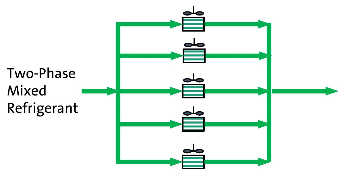
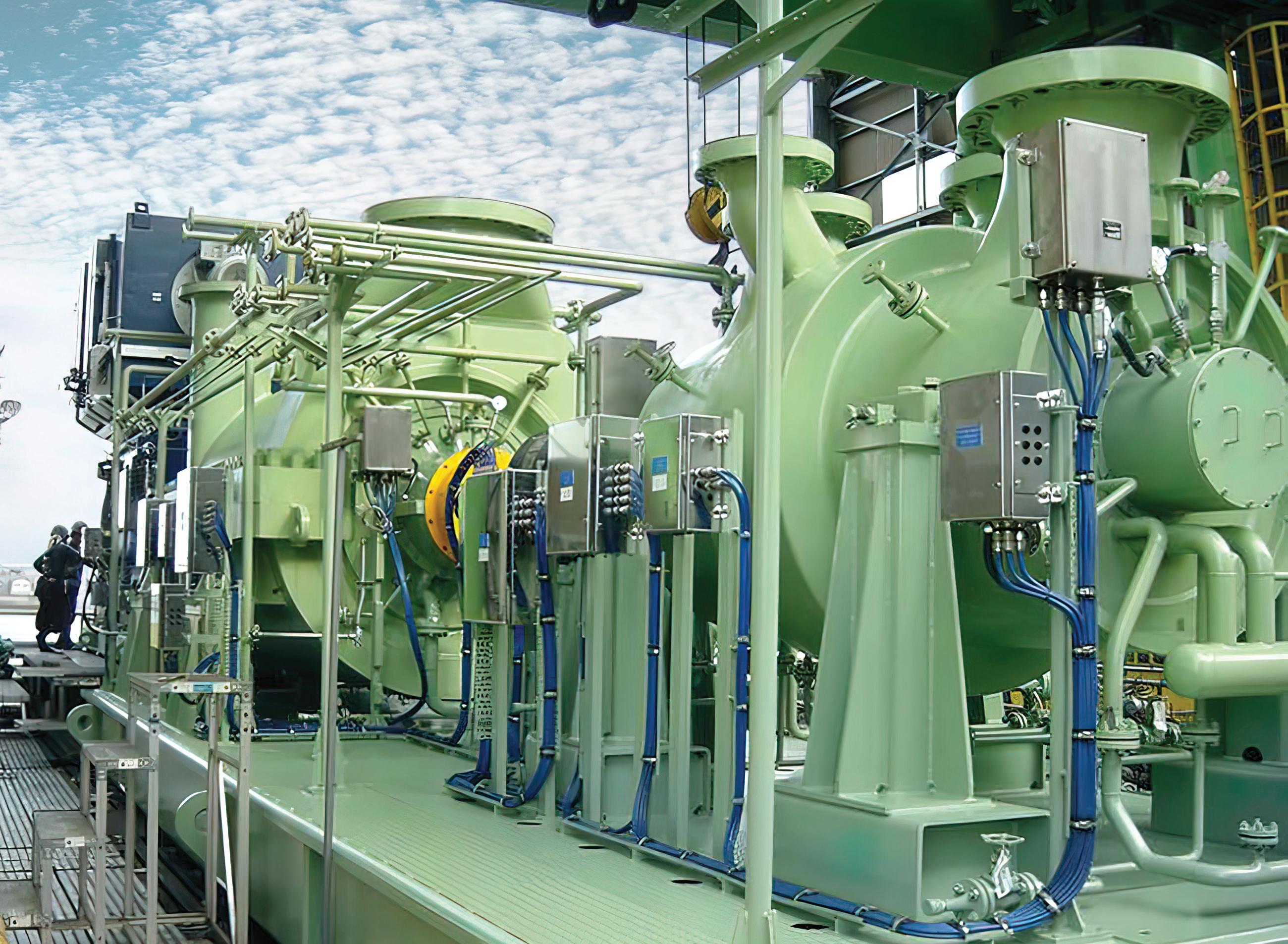
Many more tubes are required for an air-cooled mixed refrigerant condenser than for a water cooled one due to the lower heat transfer coefficient. For a mid scale or large scale DMR or SMR plant, multiple air-cooled exchanger bays in parallel with finned tubes and fans are required to accommodate the high tube count (Figure 2). For an air-cooled plant, distribution of equal proportions of mixed refrigerant liquid and vapour phases into each tube among several parallel air-cooler bays is challenging and cost-effective solutions have not been identified.

Example: Single bundle pre-cooler option
Figure 3 shows the pre-cooling section of the AP-DMRTM LNG Process employing a single bundle coil-wound heat exchanger for pre-cooling.
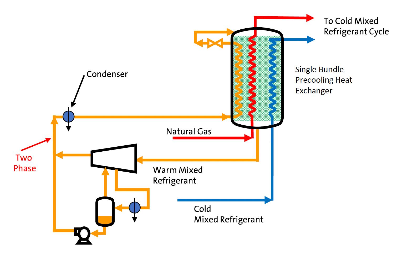
In this process, low pressure warm (pre-cooling) mixed refrigerant (WMR) is compressed in the first compressor stage, partly condensed in the WMR intercooler and phase separated. The vapour is compressed in the second stage and combined with the liquid before being totally condensed. This cycle has been successfully employed in the Coral Sul floating LNG plant. 4
Due to a small footprint and easily modularisable pre-cooling section, there has been increasing interest in the AP-DMR LNG Process for air-cooled land-based LNG plants. To assess the potential performance impact of introducing two phase WMR into multiple parallel air-cooler bays, Air Products performed a parametric
16 July 2023
Figure 1. Shell-and-tube exchanger with injection tubes.
Figure 2. Air-cooled mixed refrigerant condenser bays in parallel.
Figure 3. Pre-cooling section of the AP-DMRTM LNG Process with single bundle pre-cooler.
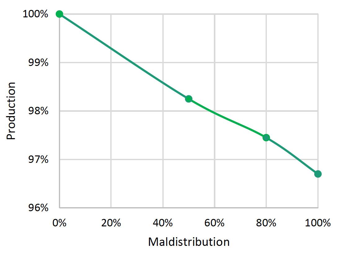
Figure 4. LNG production impact as a function of condenser maldistribution.
MHI’S HYBRID COMBINED CYCLE LNG SOLUTION
PROVIDING LOWER CARBON LNG WITH HIGH EFFICIENCY COMPRESSORS
MHI is the leading OEM to provide the highest efficiency compressors and dual-shaft industrial gas turbine driver to help meet the demand for lower carbon footprint and overall plant costs. By offering the smallest footprint and lowest CAPEX cost, MHI rotating equipment benefits LNG production to both brownfield and greenfield LNG plant developers. Learn more at mcoi.mhi.com.
 Mitsubishi Heavy Industries Compressor International
14888 Kirby Drive Houston, Texas 77047
Mitsubishi Heavy Industries Compressor International
14888 Kirby Drive Houston, Texas 77047
study evaluating the effect of varying levels of liquid-vapour maldistribution.
Figure 4 shows the results of this study. LNG production assuming fixed compressor driver power is plotted as a function of condenser inlet maldistribution. The maldistribution varies from 0% to 100%, with 0% representing perfect distribution of equal proportions of mixed refrigerant liquid and vapour phases into each tube among several parallel air-cooler bays, and 100% representing complete separation of the phases with liquid and vapour in separate tubes.
If maldistribution is small the resulting small production penalty would be acceptable; however, predicting the maldistribution is problematic. The two-phase flow through header piping between exchanger bays and between tubes within each exchanger bay is complex, making it difficult, if not impossible, to predict maldistribution and the resulting performance impact. One could design the plant with the assumption of 100% maldistribution, requiring 3.5% additional power to overcome the lower performance, but this is a significant impact to OPEX.
Example: Two bundle pre-cooler option
Figure 5 shows the pre-cooling section of the AP-DMR LNG Process employing a two-bundle coil-wound heat exchanger for pre-cooling. Air Products has developed this process in part to address concerns regarding the WMR condenser in a land based air-cooled plant.
In this process, WMR is partly condensed in the WMR intercooler then phase separated, with the resulting liquid sent directly to a dedicated circuit in the precooling heat exchanger rather than to the WMR condenser, thereby eliminating the pump used in the single bundle option. In this process, single phase fluid enters both the WMR compressor intercooler and aftercooler, eliminating the concerns about maldistribution in air-cooled condensers.
The liquid mixed refrigerant produced from the WMR intercooler is used to provide refrigeration to the warm (lower) bundle of the precooling exchanger, while the lighter liquid mixed refrigerant produced from the condenser is used to provide refrigeration to the cold (upper) bundle of the pre-cooling exchanger. Use of two different WMR compositions in the two zones of the pre-cooling exchanger provides an efficiency benefit, particularly at a 50:50 warm mixed refrigerant to cold mixed refrigerant (CMR) compression power split.
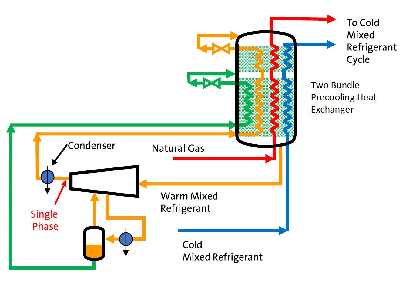
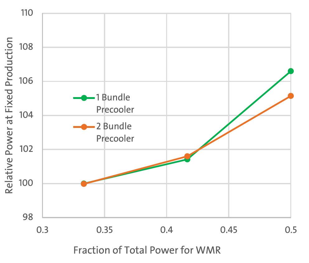
Figure 6 shows the relative power consumption of both AP-DMR LNG Processes as a function of power split, defined as WMR Power/(WMR+CMR) power. At a 0.33 power split, for example with one gas turbine driver for WMR and two gas turbine drivers for CMR, the relative power is the same. At a 0.5 power split, for example with one gas turbine driver for WMR and one gas turbine driver for CMR, the two-bundle precooler version has an efficiency advantage of around 1.5%. For both cycles, optimal efficiency occurs at around a 0.33 power split.
Summary
Air Products has developed efficient dual and single mixed refrigerant LNG processes that are suitable for both floating LNG production using water cooling, and land-based LNG production using air cooling. Unlike pure refrigerants, condensation of mixed refrigerants against an ambient heat sink presents unique challenges. Care must be taken in both the condensing heat exchanger design and liquefaction process selection to ensure that both liquid and vapour phases remain in equilibrium as the mixed refrigerant condenses.
References
1. PETTERSEN, J., and FREDHEIM, A. O., ‘Experience with water cooled mixed refrigerant condensation’ IGT International Liquefied Gas Conference Proceedings, (2010).
2. KE. H. et. al., ‘Analysis Exploring the Uniformity of Flow Distribution in Multi-Channels for the Application of Printed Circuit Heat Exchangers’, Symmetry, Vol. 12, No. 314, (2020).
3. BAEK, S. et. al., ‘Microchannel heat exchanger for two-phase Mixed Refrigerant Joule Thomson process’, AIP Conference Proceedings 1573, pp.612 – 617, (2014).
4. ‘Mozambique’s first LNG cargo departs from Coral Sul FLNG, offshore the Rovuma basin’, Eni, (13 November 2022), www.eni.com/en-IT/media/pressrelease/2022/11/eni-coral-first-cargo.html
18 July 2023
Figure 5. Pre-cooling section of the AP-DMR LNG Process with two bundle precooler.
Figure 6. Relative power as a function of power split.
s the world moves towards decarbonisation, the benefits of LNG are widely apparent. It is clean and quiet burning, abundant, and easily stored. Its simple dispensation is convenient for truck-refilling, with the most traditional familiarity.


Why then, are there only 635 fuelling stations across Europe?
Despite almost doubling in size in the last two years, LNG still significantly trails behind compressed natural gas (CNG), which boasts 4159 stations across the continent.1 The bulk of LNG stations are concentrated in Germany, which hosts 162 stations, followed by Italy with 130, and Spain with 90.
19
Dover Fueling Solutions, Europe, consider the benefits of using LNG as an alternative fuel.
So, what is contributing to this slower uptake and why are more new LNG-powered vehicles not being registered by fleet owners? Can LNG become the odourless, colourless, non-toxic, clean fuel of the future, and what infrastructure will be required to enable this?
Seemingly, soaring gas prices and economic uncertainty have been the main barriers to adoption thus far. Fuel retail businesses and fleet owners appeared reluctant to invest in new, clean fuels until the market settled and prices started to reduce to current levels.
One company facilitating this transition to cleaner fuel is Dover Fueling Solutions (DFS). The company offers fuelling retailers a highly-effective total cost of ownership (TCO) model with its LNG dispensers and LNG fuelling technology,

in addition to its innovative boil-off gas treatment unit (BTU) management solutions. This is all supplemented by a comprehensive ‘after-care’ package which means the company remains involved, through its LIQAL brand, in the project to keep the station up and running for customers.
Boil-off gas: cost-effective solutions
One of the challenges of storing LNG is the accompanying boil-off gas (BOG). When heat enters the cryogenic storage vessel, BOG is continuously evaporated. Releasing this into the atmosphere must be avoided at all costs.
BOG contains methane – a harmful greenhouse gas. This will soon become illegal as part of the European green deal. Typical practices, such as venting or flaring methane, are also soon to be banned.2 Evaporated BOG – which is simply vented away – will also result in stock loss, which can hurt businesses fiscally too.
To combat this, DFS has a BOG treatment unit that converts BOG back to its harmless liquid form and keeps it, for an unlimited amount of time, in the storage tank – the LIQAL BTU System.
The benefits of this system are threefold: the process is environmentally friendly, it ensures unlimited shelf life of LNG in the tank, and it also has a low TCO. Environmentally, the LIQAL BTU system eliminates the venting of BOG in a cost-effective way that does not impact LNG deliveries or demand active management from forecourt owners. Furthermore, its components are built to last, field-proven, and require fewer maintenance interventions.
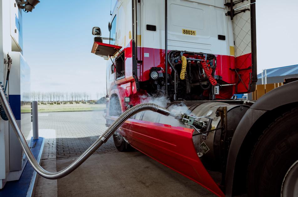
Moreover, it has the ability to provide cold LNG to trucks. Ultimately, the temperature of the LNG will affect the range output of the vehicle. Excessive LNG temperatures will cause shorter vehicle ranges, so it is important for forecourt owners to install solutions that can help keep LNG as cool as possible. The LIQAL solution avoids the high operating expense, possible carbon dioxide (CO2) release, and site risk that comes with the alternative BOG solution – cooling with liquid nitrogen.
Station after-care
One main concern for station owners, amidst fluctuating market forces, is staying informed of day-to-day operations through key performance indicators (KPIs) and other metrics. This can include availability, sales info, fuelling process data, and dispenser usage. LIQAL’s aftercare solutions can enable this.
The advanced SCADA system offers real-time, user-friendly dashboards with strong functionality for station KPI report generation. This can help station owners access real-time information with an intuitive overview of the station, right at their fingertips. This includes monitoring storage tanks, and controlling unloading and refilling. In-keeping with modern working patterns, this can be accessed via web browser from anywhere at any time.
Remote performance is managed by a skilled team of engineers, with customer support keeping an eye on fuelling performance to ensure a reliable and consistent fuelling experience. This service means that station owners do not need to be actively involved at all times and can rely on experts to manage operations.
Physical station after-care training sessions can include on-site station inspections, maintenance, and service activities.
20 July 2023
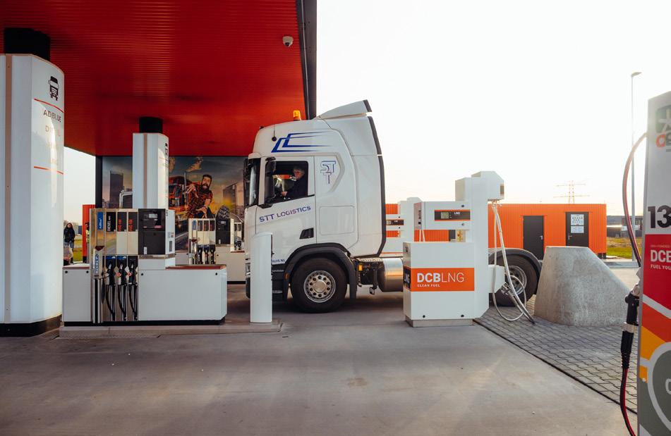
Figure 1. DCB LNG Borne.
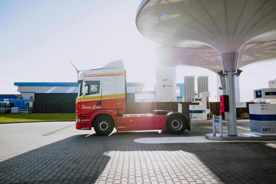
Figure 2. NXT LNG station, Rolande Alkmaar.
Figure 3. DCB LNG Borne.
Everything is in order to ensure maximum station availability during the years of commercial operation.
Case study: creating a consumer-centric model
If – like its benefits would suggest – LNG is going to play a big part in the future of commercial transport, dispensing needs to be intuitive and consumer friendly. As demand for greener energy grows higher every day, so will the need for bespoke LNG service stations. This includes standard LNG and the fully sustainable variant, bio-LNG – renewable LNG made from waste materials.
But what could this LNG model look like in practice?
Well, it is clear that, much like its traditional petrol and diesel counterparts, LNG has the potential to become a mainstream retail fuel. This would, however, require a very consistent and reliable fuelling performance.
DFS can help to facilitate this. Through its LIQAL brand, DFS can design a completely, bespoke and integrated LNG station with advanced LNG technology.
At the heart of this new LNG forecourt should be the state-of-the-art fuel dispenser. These should be reliable for everyday use, assembled from corrosive-proof materials to withstand even the harshest weather conditions and suited to all extremities of the European climate. Their modern design should be compatible with the customer able to choose their own filling conditions – namely, cold or saturated LNG fuel.
This should be coupled with a user-friendly, modern interface at the pump. This can include a euro-centric, touchscreen display where truck drivers can select their preferred language and pay quickly at the pump for ease of convenience.
Modern problems require modern and safe solutions. This is especially true of the LIQAL LNG dispenser which has been engineered with safety in mind. This model includes a patented nozzle docking bay, heated and purged for tension-free connectivity, and a long hose and nozzle life, limiting the occurrence of leakages.
The inherent robustness of these materials will also enable use in the most demanding of environments, which should mean a low TCO for the fuelling retailer.
Is this the future of commercial transport?
Clearly, from the advent of this cutting-edge technology, it is apparent that LNG will be a part of the decarbonisation mix alongside fellow market leaders, electricity and hydrogen.
The market has been buoyed recently by the launch of Volvo’s new bio-LNG truck,3 which it claims can reduce CO2 emissions by 100%. The vehicle also boasts a 10% larger gas tank that makes it up to 4% more fuel efficient and contributes to a longer range. This has enormous potential for the commercial transport sector.
Clearly, the forecourt will have to be prepared for this new model to roll onto the market with ‘Volvo ready’ functionality to handle venting and filling through the same connection.
To make it mainstream, LNG infrastructure needs to improve. For forecourt owners looking to make the switch, they need to look to partner with experts who can construct the ideal station – laying the foundation for development of this infrastructure. From the highest safety specification to the
most advanced technology, companies such as DFS can help aid this transition.
References
1. ‘Europe now has 635 LNG fueling stations’, LNG Prime, (24 January 2023), https://lngprime.com/europe/europenow-has-635-lng-fueling-stations/71712/
2. ‘Member States agree on new rules to slash methane emissions’, Council of the European Union, (19 December 2022), www.consilium.europa.eu/en/press/ press-releases/2022/12/19/member-states-agree-on-newrules-to-slash-methane-emissions/
3. ‘Volvo launches new bio-LNG truck’, LNG Prime, (2 February 2023), https://lngprime.com/europe/volvolaunches-new-bio-lng-truck/72615/
July 2023 21
Figure 5. DBC LNG, Borne.
Figure 4. NXT LNG station, Rolande Alkmaar.
Stefano Calandri, Vanzetti Engineering, Italy, describes how pumps can be used to help the LNG market transition to a cleaner future.

22
In terms of emissions, LNG used in maritime transport allows for zero sulfur oxide, 85% less nitrogen oxides, 95% less particulate matter, and also a containment, in the order of 20%, of carbon dioxide emissions. Even though it is still a fossil fuel, LNG represents a hypothetical bridge to new alternative fuels because it can be integrated with bio-LNG, thus paving the way for further developments in this field.
As for LNG, the energy security aspect must also be considered: the recent increase in demand is also related to the choice of European governments to drastically reduce dependence on Russian gas. The increasing use of LNG in the naval sector is possible due to rising trade flows to Europe. LNG carriers aim to progressively replace the gas previously transferred via pipelines between Russia and Europe. Therefore, in the short term, LNG is confirming itself as the only viable solution for shipping and is likely to lead to a further increase in LNG-fuelled ships in the coming years.
All of this represents a high-impact technological transition. The entire supply chain of methane transport using ships as an alternative to pipelines is essentially based on cryogenic systems and applications.
The marine LNG market
Vanzetti Engineering has developed a complete range of pumps and cryogenic components for the main areas of LNG use: automotive, industrial, and marine.
In particular, the company’s core business is naval applications – there has been a significant increase in demand in this sector, from shipowners and shipyards, especially from the Far East, for example China and South Korea.

This trend shows that a major path of the energy transition is at hand. What is driving the change is first and foremost the environmental need, as methane is generally less polluting than traditional hydrocarbons.
The company’s pumps are able to address the two main areas of technology relating to liquid methane engines, both high and low pressure. Depending on the case, there are different pump types, as they must be able to meet different requirements. For example, there are reciprocating pumps (VT-3) or low-pressure pumps (from the Artika series), as well as centrifugal pumps, or even a combination of the two.
23
In the equipment of a ship, what differs the most is not so much the operating pressure, which normally follows standard parameters, but the flow rate, which can vary greatly depending on the size of the engine and the speed the ship can reach.
Consultancy, design, and certification: a long journey
When dealing with certain installations, especially those that are used in the marine environment, not everything is 100% defined at the time of contracting. There are several details that have to be finalised later, and, in addition, a number of documents have to be produced for validation not only by the customer, but also by certifying bodies, which in the marine sphere are in charge of class certification. These bodies are third-party organisations that guarantee the conformity of the design, as well as the performance of functional pressure tests and everything related to the completion of each individual project. Certifications are mandatory in each sector; in the marine sector, it is a fundamental aspect that customers would expect as part of the contract.
The customer’s requests usually involve a specific performance requirement that may entail pressure and/or flow values, depending on the liquid gas used; methane or other cryogenic gases, such as nitrogen and oxygen. Once the customer’s needs are understood, Vanzetti Engineering proposes the best technical solution, also considering the context in which the customer plans to use it.
With particular reference to the marine sector, the initial requirement is the one set by the shipyard or the shipowner that requires a certain type of product that, again, takes pressure and/or flow values into account. An important factor is redundancy, since the systems must have this requirement on
ships in order to guarantee safe navigation, even on the high seas. In fact, each type of on-board service always requires more than a single pump, i.e. a system consisting of at least two twin pumps.
The company pays particular attention to understanding how it is being contextualised. This practice is highly diversified, depending on the context and substantially based on the experience it has developed over the years in the various application areas where it has been operating.
Once the right solution has been identified to fulfil the customer’s requirements, the order is placed. At this point, the design stage begins, which includes the generation of a whole series of documents, such as the general assembly drawing, the BOM, etc., which are submitted to the certification bodies and, of course, to the customer for approval.
Once approvals and certification have been obtained, the task passes to the logistics department, which enters the list of parts required for the construction into the company’s management system, showing the relevant construction specifications. This is a highly critical aspect from the point of view of the production process, as it is at this stage that the basis is laid for determining the product’s production time. For example, a component may also include sub-cycles as well as a painting process; thus, suppliers can be identified. All of this information, together with the specifications described, is passed on to the purchasing department in charge of selecting suppliers, and the order is placed so that the project deadlines are met.
The time factor is crucial since it represents not only the delivery date, but an entire flow consisting of numerous stages. In fact, the delivery date is the reference with which one proceeds backwards to first determine a date for acceptance, which is often carried out in the presence of the customer or alternatively via remote connection.
A project, scheduling, and production Gantt is used to check schedules, which includes all phases: order acquisition, design, procurement, manufacturing, testing, and shipping.
Other endeavours
On the horizon for Vanzetti Engineering is not only the market, but also the spirit to take the opportunity to make its own contribution to scientific research, as demonstrated by its collaboration with the Aria Project, promoted by the National Institute of Nuclear Physics (INFN). The aim of this project is the direct detection of dark matter.
The project involves the construction of the distillation column for liquid nitrogen. In this particular project, Vanzetti Engineering provided two liquid nitrogen booster pumps that are used to move the liquid nitrogen from the bottom to the top of the column.
Conclusion
The LNG sector is constantly changing as the world undergoes an important phase of energy transition. Furthermore, storage facilities, as well as regasification units, are increasingly proliferating. The growth in the use of LNG in the marine sector is also opening the door to new development opportunities in terms of both a new transport concept, and the technical and fuel supply chain that has been created. Vanzetti Engineering, through its technology and its products, is part of the change and aims to make its own contribution by working alongside the customer to find the best solution, which allows LNG to be used in all its forms, advantageously and safely.
24 July 2023
Figure 1. Reciprocating pump.
Figure 2. Centrifugal pump.
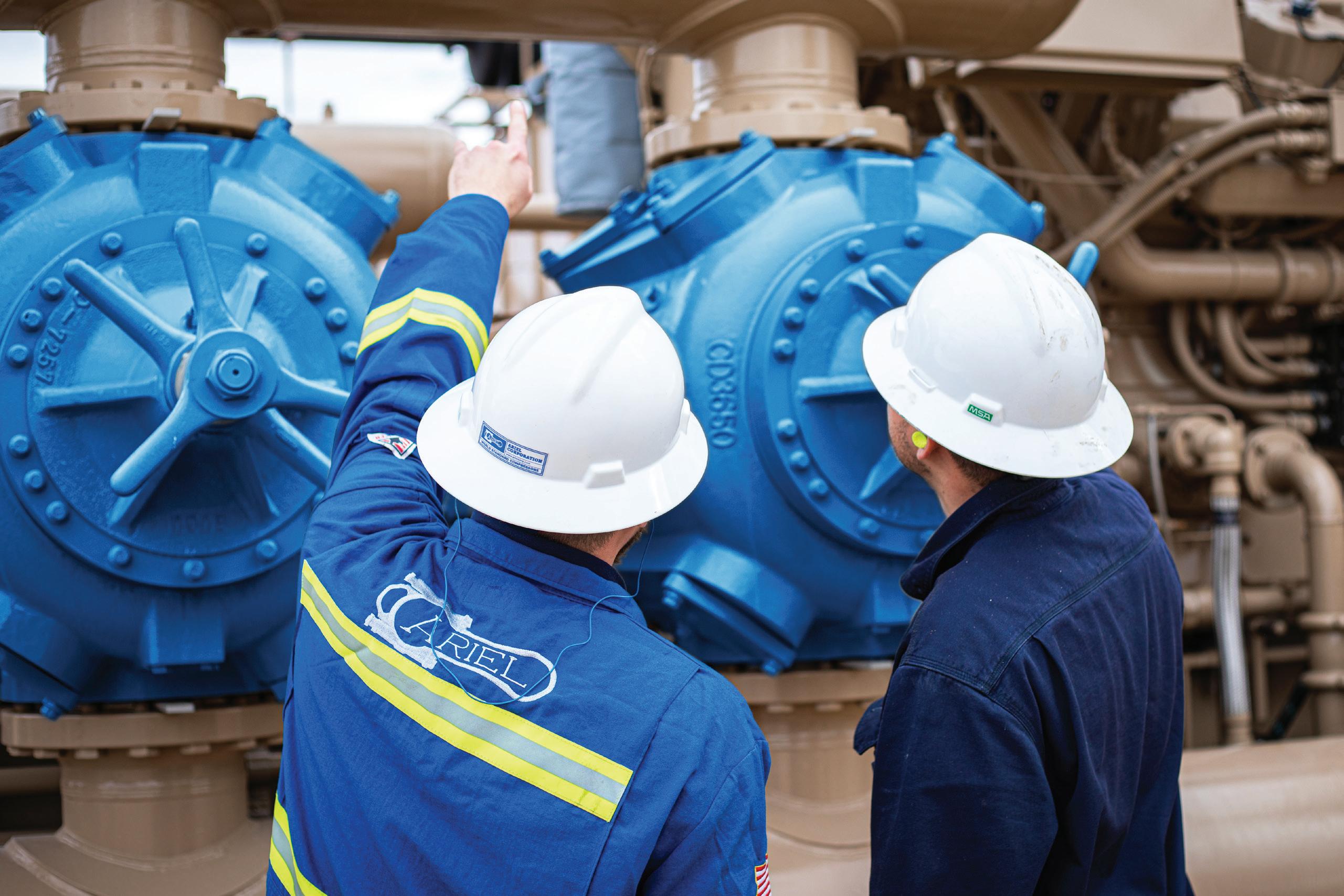
Joseph C. Fernandez, P.E., Manager, Application Engineering, Ariel Corporation

Joe Fernandez manages the Applications Engineering Department at Ariel Corporation. He has been with Ariel Corporation for over 26 years, and in the energy industry for over 38 years, responsible for engineering compression systems in the upstream, midstream, and downstream markets. This experience has included compressors used for feeding and offloading LNG terminals, as well for gathering, pipelines, storage, acid/sour gas carbon capture, utilisation, and storage, and vehicle fuelling.
Andrea Masi, Compression Product Platform Manager, Baker Hughes
Andrea Masi leads Baker Hughes’ Compression Product Platform team, to define and execute the multi-generational product plan for centrifugal compressors, reciprocating compressors and turbo-expanders solutions. His career spans 21 years in strategic marketing product management and R&D advanced technology engineering across energy and industrial sectors. He graduated in Electronic Engineering at the University in Florence (IT).
Francesco Cangioli, Compression R&D Engineering Manager, Baker Hughes
Francesco Cangioli is New Product Development Manager, leading a team focused on compressors and expanders. Following a Masters Degree in Mechanical Engineering and a PhD in Reliability and Availability in Industrial Engineering at the University in Florence (IT), he has been part of Baker Hughes since 2012, covering multiple roles innovating on gas turbines, pumps, expanders, and compressors.
Serge Staroselsky, Chief Technology Officer, Compressor Controls Corporation
Serge Staroselsky has been with Compressor Controls Corporation (CCC) in various roles for over 25 years, assuming his current position in 2014. He works in product and technology development and has extensive experience in designing and implementing control systems for turbomachinery, specialising in antisurge control and protection and compressor capacity control, covering a variety of applications. He has a B.S. degree in Mechanical Engineering from the University of California at Berkeley and an M.S. in Mechanical Engineering from the University of Minnesota.
Jens Wulff, Managing Director, NEUMAN & ESSER Deutschland
Jens Wulff has extensive experience in compressor technology. He started as a Project Manager, became Area Sales Manager, and later Managing Director of the compressor production companies at NEUMAN & ESSER. Today, he is Managing Director of NEUMAN & ESSER Deutschland, the new machine company in Germany. Wulff has successfully managed several sales projects of LNG compressor systems over the years, including the first LNG boil-off gas compressor with innovative stepless reflux power control in 2016.
Arnd Viets, Managing Director, NEUMAN & ESSER South East Asia
Arnd Viets has held various positions at NEUMAN & ESSER. Among these, he supported the Asian branches in India and Thailand with technical support. Since 2014, he has been Managing Director for the first-class compression equipment at NEUMAN & ESSER South East Asia and is responsible for the Asia Pacific region. The high demand for LNG terminals worldwide and his strong technical background led him to develop highly efficient LNG terminal solutions.
LNG Industry asked several companies to discuss some key topics regarding compressors in the LNG industry.
25
Q1. How do compressors improve the efficiency of the LNG process?
Joseph C. Fernandez, Ariel Corporation
The flexibility provided by reciprocating compressors allows for the reduction in offloading pressures prior to being put into sales lines (inlets at storage facilities prior to the liquefaction), thereby improving the overall efficiency of the LNG plant. Another area where reciprocating compressors are used and help improve overall efficiency is as vapour recovery units, also due to the wide range of operating pressures under which they can run.
Andrea Masi and Francesco Cangioli, Baker Hughes
Compressors are the technological heart of the LNG process, playing a key role in performance and overall total cost of ownership (TCO). Improvements in compressor efficiency reduce power consumption, leading to a reduction in fuel or electricity consumption – depending on the driver adopted, and whether it is a gas turbine or electric motor. A compressor’s higher efficiency is achieved through new technology injection, new impellers profile, and new seals: this is key for new LNG projects and also allows for upgrading existing assets to maximise output. Improving compressor efficiency (average +4% in the last three years through aerodynamic improvements) does not impact only consumption, but also directly abates emissions, providing a double benefit to the plant operator.
Serge Staroselsky, Compressor Controls Corporation
From the point of view of a control system, first of all, capacity control of compressors should be a part of the overall LNG process control strategy; secondly, optimising loadsharing for parallel compressors; thirdly, minimising recycling with small antisurge margins; and, lastly, simplifying start-up and shutdown operations, reducing start-up time. For example, for some types of LNG processes, the control system typically maintains inlet header pressure for each refrigeration service, where the setpoints for the pressures can be derived by the overall plant optimiser. For other processes, different process parameters can be used as PVs for capacity control and integrated within overall optimisation scheme. Often, it is assumed that given the desire to produce maximum LNG rates, all refrigeration compressors operate far from the surge region. However, this is not always the case, particularly in climates where the design has to cover wide range of ambient temperatures. A compressor control system that is a part of the overall optimisation scheme must be able to operate in a stable manner while recycling and maintaining margins of <=10%, reliably preventing process upsets resulting in surging of the machines.
Jens Wulff, NEUMAN & ESSER Deutschland, and Arnd Viets, NEUMAN & ESSER South East Asia
By using efficient compressors, the LNG process can be improved significantly. For boil-off gas (BOG) management, efficient piston compressors are the best choice.
NEUMAN & ESSER uses contact ring type machines with low internal leakage for these processes. As the BOG flow rate varies a lot, we also use efficient capacity control methods to save energy and reduce carbon dioxide (CO2) emissions.
Q2. What factors are considered when deciding which compressor technology is needed for an application?
Joseph C. Fernandez, Ariel Corporation
The primary considerations in compressor selection are inlet and discharge pressures and required throughput. These will determine the best technology for the project, as well as the size and number of units required. Positive displacement compressors, such as reciprocating compressors, are good for high-discharge pressures and moderately high throughputs, and can accommodate a wide range of operating pressures; while rotary screws are well suited to low inlet pressures and very high throughputs, at lower discharge pressures. Dynamic compressors, such as centrifugals, are designed for very high throughputs and moderately high discharge pressures, with axial compressors providing the highest throughput capabilities and considerably lower pressure capabilities. Another consideration is the type of prime mover needed. Natural gas engines and electric motors are well suited for driving reciprocating and rotary screw compressors, whereas a turbine being used as a centrifugal compressor is a better solution.
Andrea Masi and Francesco Cangioli, Baker Hughes
Multiple factors are considered when selecting the most appropriate compression technology for the application, and usually include efficiency and availability. Indeed, the main drivers are flow and pressure that typically identify the most relevant technologies, such as compressor size and impeller types, then footprint, particularly for floating LNG (FLNG) applications. Typically, key decisions are driven by specific customer needs and by TCO, balancing CAPEX and OPEX of the solution. For example, the same service could be delivered with a larger compressor and higher efficiency to increase the diffusion ratio, or a smaller compressor with slightly lower efficiency (-2%) but with a weight benefit of about 20%.
Serge Staroselsky, Compressor Controls Corporation
From a control system vendor’s perspective, it appears that the process design and capacity requirements play a dominant role in compressor technology selection. Up until recently, it seemed that improvements in process efficiency demanded larger capacity centrifugal compressors, up to 100 MW in a single casing, often driven by single-shaft gas turbines with limited rotating speed operating range. Today’s trend seems to be toward smaller capacity centrifugal units, and with the plant having multiple trains to meet overall capacity requirements. It seems that the trend is also toward simplification of the control system and avoidance of compressors operating in parallel due to perceived complexity. However, in CCC’s
26 July 2023
COMPRESSION YOU CAN COUNT ON
For our customers, compression is critical – always. So when they need us, we spring into action. Ariel works to build and maintain a trusting relationship that grows stronger with time. We look at everything from our customers’ perspective, so we can truly understand the best ways to make their operations more successful.

Compression you can count on, now and always.
www.arielcorp.com
experience, compressors can be reliably operated in parallel, especially for units having an operating range of at least 85 – 105% of rotating speed, and the complexity of parallel operation should not influence the design toward reducing overall efficiency per train, that is, increasing process and compressor efficiency should take precedence over the complexity of controls.
Jens Wulff, NEUMAN & ESSER Deutschland, and Arnd Viets, NEUMAN & ESSER South East Asia
Determining factors include flow rate, flow and pressure fluctuations, and available space. Turbomachinery is best suited to high-flow scenarios under constant conditions, whereas reciprocating compressors are very well suited to variable flow rates and pressures from low to high. The available space influences the choice of whether a horizontal, vertical or V-type compressor is used.
Q3. How are compressors helping to reduce emissions (e.g. carbon dioxide) from the LNG process?
Joseph C. Fernandez, Ariel Corporation
Reciprocating compressors within the LNG process rely on a pressure packing case which seals around the reciprocating piston rod. Ariel employs solid ring technology in the packing cases which contains processed gas by eliminating the leak paths of conventional segmented ring sets. The company’s packing cases typically reduce fugitive emissions to meet or exceed Environmental Protection Agency (EPA) regulations. This packing design is also very reliable, providing improved time between maintenance cycles. Reciprocating compressors are also being considered to collect flare gasses, reducing carbon dioxide emissions. Reciprocating compressors are also proving to be the solution of choice for carbon sequestration trains associated with LNG export facilities.
Andrea Masi and Francesco Cangioli, Baker Hughes
The main driver to decarbonise the LNG process is compressor efficiency. With a history of 30 years in LNG installations, Baker Hughes brings a track record of continuous efficiency improvement, with plants that have seen an efficiency increase of up to 5 – 6% when duplicating trains over a 5 – 10-year timeframe. At the same time, the company has seen a trend in power density, around maximising throughput while reducing the compressor size – up to the recently developed high pressure ratio compressor (HPRC) that unlocks a dramatic reduction in the number of casings (allowing to compact up to three casings in one). The impact is a reduction in emissions from dry gas seals, along with overall lifecycle impact.
In some cases of a smaller size, hermetically sealed electric technology, such as the Baker Hughes’ integrated compressor line (ICL) is an effective solution. ICL is a zero-emissions compressor during operation and pressurised standby. Being an electrical driven compressor, emissions are proportional to electrical grid power generation emissions. In case of green
electrical power, ICL is removing up to 99% of emissions compared to gas-fired solutions.
Serge Staroselsky, Compressor Controls Corporation
Again, from the perspective of a control system for compressors, the main factors in reducing emissions are avoidance of trips and large pressure fluctuations, which can lead to flaring and result from the inability of the control system to handle disturbances. In addition, optimal loadsharing between units and reduced recycling can lead to reduced power consumption and thus reduced emissions. Loadsharing and well responding control system are very important for BOG compressors where inlet conditions can rapidly change due to various modes of operation, with incoming gas of widely different temperatures. Observing operations at a large plant with multiple trains, it appears that disturbances occur fairly often, due to maintenance activities on various trains, so the response of a control system plays an important role in maintaining stable operation. Technological advancements may further reduce emissions, however, there is still a lot that can be done today to reduce emissions through better controls.
Jens Wulff, NEUMAN & ESSER Deutschland, and Arnd Viets, NEUMAN & ESSER South East Asia
Compressors can be used to re-liquify the BOG or make use of it as a fuel. This avoids flaring the BOG without a use and saves a lot of CO2. As the compressors are mostly electrically driven, a higher compressor efficiency saves electrical power which also has a specific CO2 footprint.
Q4. What component of a compressor is most prone to failure and thus requires the most maintenance?
Joseph C. Fernandez, Ariel Corporation
Valves. Valves consist of a sealing element, often with damping plates and damping from the gas. As a spring mass damped system, the valve motion is optimal at one condition, with fair motion across a small range. The factors defining the range include operating pressure, both suction and discharge, operating speed, gas composition, temperature, and valve design. Gas cleanliness also plays a role in valve reliability. Valve reliability can be optimised through upfront design and monitoring for changes in conditions.
Andrea Masi and Francesco Cangioli, Baker Hughes
Unlike other applications such as those in upstream, the LNG mission profile is usually characterised by stable operations and clean gas. Compressor failures are quite rare and tend to be due to the wear on components, such as dry-gas seals. These components require dedicated preventive maintenance and advanced prognostic services to monitor their operating performance and identify potential failures in advance. Through advancements in the 24/7 remote monitoring of LNG compression trains worldwide, Baker Hughes has reached 99+%
28 July 2023
A whole new way of thinking about compression technology

Backed by 60 years of industry-leading compression design, our High Pressure Ratio Compressors (HPRC) provide significant improvements in overall H2 plant footprint. They're 50% smaller and 30% lighter than traditional centrifugal compressors, and can reach 3:1 pressure ratio—with high reliability and availability.
Get the higher pressure you need in the smaller package you want.
bakerhughes.com
Copyright 2023 Baker Hughes Company. All rights reserved.average availability, enabling LNG players to maximise their production and reduce operating costs.
Jens Wulff, NEUMAN & ESSER Deutschland, and Arnd Viets, NEUMAN & ESSER South East Asia
For reciprocating compressors, the valves at the cylinder inlet and outlet are the most failure prone component. Monitoring their behaviour, e.g. via temperature, vibration, and sound measurement, is key for avoiding unplanned shutdowns.
Q5. With new LNG markets arriving and others expanding, how is compressor changing/adapting?technology Are there any limitations?
Joseph C. Fernandez, Ariel Corporation
A major area of advancement in reciprocating compressors is the incorporation of smart technologies, such as machine monitoring, and predictive maintenance. These enhancements allow for better planning of shutdowns, and ensuring that critical parts are on hand when needed, thereby minimising downtime. Another area is automation in particular where measured process data is used with a programmable logic controller (PLC) to control compressor performance based on plant needs. Examples of automation include electric motor-driven units utilising variable frequency drives to control speed, and automated compressor unloading devices, such as Ariel’s eVCP, providing efficient and effective methods to control throughput and fuel usage.
Andrea Masi and Francesco Cangioli, Baker Hughes
LNG demand is growing, and additional projects FIDs are needed shortly. Analysing the technical requirements, the company can see an increase of electric motor and high-efficient aeroderivative gas turbines (such as the Baker Hughes’ LM6000PF+ or the LM9000) driving compressors instead of traditional heavy-duty gas turbine – mainly in operation in mature projects. Looking at the entire refrigerant train size, the preferred choice is a multiple number of mid-size trains modularised vs traditional large trains stick built.
Baker Hughes’ mid scale solution is the perfect fit for those projects where time-to-LNG, lower production costs and project de-risks are key priorities. Combining electric motor compressors with more efficient power generation island, operators are able also to reduce plant carbon footprint. The company’s compression technology can be tailored to different approaches, traditional and modularised, providing the best compromise between performance optimisation and standardisation.
Serge Staroselsky, Compressor Controls Corporation
There seems to be a trend for new plants toward electric-driven packages, and generally, toward pre-packaged modular solutions, with trains of approximately
0.5 –1.5 million tpy capacity. Whether this trend will stay and expand depends on the performance of some of the newly commissioned plants using the modular approach with multiple trains. For control systems the general trend is toward more autonomous operation, which is particularly important for remote locations, where experts can access the system, or at least information from the system, without having to be on site. Building a safe communication infrastructure remains a challenge at some locations and places limitations on the availability of remote access.
Jens Wulff, NEUMAN & ESSER Deutschland, and Arnd Viets, NEUMAN & ESSER South East Asia
There are currently no real limitations. Progress is made on controllability and online-monitoring for predictive maintenance. With the digital NEA|XPLORE system, NEUMAN & ESSER has its own platform for data collection and analysis for machine health, maintenance planning, and corrective measures.

Q6. Detail the process and design behind one of your most popular compressors.
Joseph C. Fernandez, Ariel Corporation
Ariel Corporation continuously improves designs and uprates the capabilities of our compressors. New designs and improvements start with input from its customers. The design engineers develop the concepts taking into account the company’s vast field experience and what it has learned in its state-of-the-art R&D facility. Multi-department teams work together to make sure the new products meet the demands of the markets, and provide good value to the customer and exceed equipment uptime expectations.
Andrea Masi and Francesco Cangioli, Baker Hughes
Baker Hughes is always active in technology development, investigating frontier technologies and developing solutions that can meet the market’s requirements. It is continuously working on improving and enhancing thermodynamic stages, materials, and internal sealing and bearings, as well as on digital solutions.
Each development goes through a structured design process that is rigorous in terms of quality, allowing some flexibility in the required steps to be followed based on its complexity.
For a stage family release (continuous envelope of phi, mach, and diameter), the average time is usually four years, from the preliminary design, going through the complete experimental validation in a fully instrumented in-house test rigs and to releasing the geometry and performances database to be offered.
Baker Hughes introduced advanced artificial neural network and early validation tests (simplified model test fed with rapid prototyped impellers), which has drastically reduced the development time to two years, and is ready to meet new market demands, including carbon dioxide and hydrogen.
30 July 2023
The Leader in LNG Turbomachinery Optimization
CCC turbomachinery controls are used in over one hundred largescale LNG trains around the world, which contribute to 95% of the world’s overall LNG MTPA capacity. We ensure the optimal design and operation of LNG trains to help you get the most from your project.
LNG plants trust CCC to optimize and control some of their most critical parts. End users, engineering contractors, EPCs and operators have confidence in our technology thanks to our 45+ years of turbomachinery expertise and the tens of thousands of non-LNG plants using our solutions.
From early optimization in pre-FEED and FEED, CCC helps customers avoid risks and reduce costs. 150+ engineers and subject matter experts stationed across the globe, we always have someone close by to support your operation.
CCC provides industry-leading technology, innovative engineering solutions and an unyielding focus on efficiency, reliability, safety, and your bottom line.
CCC Global Headquarters (Des Moines – USA) 4745 121st Street Des Moines, IA 50323-2316 USA +1-515-270-0857 www.cccglobal.com Contact your nearest CCC account manager for additional information, or visit: www.cccglobal.com/contact-ccc/
For hydrogen compression, the company is delivering the first units of the HPRC. This is a strong fit for this application due to its capability to run 40% faster than conventional compressors, while allowing an improved rotodynamic. This solution has been widely tested internally from the mechanical and thermodynamic perspective in the past few years, making it ready to be adopted today.
Jens Wulff, NEUMAN & ESSER Deutschland, and Arnd Viets, NEUMAN & ESSER South East Asia
Using its unique design tool ‘KO3’, NEUMAN & ESSER can carry out all technical tests from an installation and performance point of view for the most critical operating cases and special/offset operating cases with one mouse click. This allows the company to provide comprehensive support in the design and optimisation of the compressor system and the entire process. Specifically for BOG compressors, the company can detail various scenarios during commissioning and operation.
Q7. Detail a short case study of a compressor installation at a stage of the LNG process.
Joseph C. Fernandez, Ariel Corporation
Ariel compressors are utilised throughout the entire process of production, processing, and transportation of natural gas globally. With over 67 000 compressors shipped since 1965, most of the gas produced in the US has been compressed within an Ariel on its way to becoming feedgas for LNG terminals.
Andrea Masi and Francesco Cangioli, Baker Hughes
Baker Hughes’ projects with Qatargas (QG)1 are a good representation of the evolution of its compression technology over the years. Following up on the three compression trains installed at Qatargas 1, Baker Hughes was asked a few years later to support a series of major expansion projects for Qatargas and Ras Laffan LNG Company. In 2009, Qatargas 2 started production, and this is the best example of how the evolution in compression technology improves the value that the company delivers to the customer. The project objective was to double plant production, starting from an already large production plant.
Increasing the driver size, QG adopted a Frame 9E gas turbine; consequentially, larger compressors were needed to handle higher capacity with a lower speed than before. This required unprecedented casing and impeller sizes up to 1800 mm. This was within the capabilities of Baker Hughes’ manufacturing facility in Florence, Italy (centre of excellence for compression technology), that can machine compressor casings with internal diameters up to 12.4 ft (3800 mm), and 3D shrouded impellers with diameters exceeding 6.5 ft (2000 mm) from a single forging. Dry gas seals with internal diameters of 1.14 ft (350 mm) were also qualified.
Since then, Baker Hughes’ compression technology has further evolved in a number of ways. An improved casing design reduced the rotor length, allowing the adoption of the
power density concept for the compressor design. This evolved design led to a smaller impeller diameter with a larger flow coefficient that, together with the development of new high mach stages with mixed flow design, led to a casing diameter reduction between 10% and 20% depending on the compressor, and a weight reduction between 5% and 10% handling the same flow.
Today, an improved stage efficiency (about 3%) drives a heavy impact on emissions and fuel consumption.
Serge Staroselsky, Compressor Controls Corporation
For a control system installation for a Conoco-Phillips cascade process, a plant has multiple LNG trains, with each train including parallel propane, ethylene, and methane compressors. The compressors are driven by aero-derivative gas turbines with 20% speed variation. Control system maintains the process variable of each refrigeration service and loadshares between parallel units. Operations can adjust the control setpoints from plant distributed control systems, either manually or via plant optimiser, and thus simultaneously change performance of parallel units, without the need to manually adjust individual machines. The units may operate with some recycle on hot ambient days and surge margins are on the order of 10% or even less, yet the system operates in a stable manner and can handle most disturbances. There are also multiple centrifugal boil-off gas (BOG) units driven by a constant speed electric motors and equipped with IGVs and operating in parallel. During a transient condition, it is very important for all BOG parallel units to respond simultaneously with their inlet guide vanes – essentially, all BOG units must respond as one, otherwise the BOG header pressure fluctuations may cause flaring. In the near future, high speed data capture from the control system will be made available to a plant historian, so that plant engineers will have familiar and easy interface to high resolution data for analysis.
Jens Wulff, NEUMAN & ESSER Deutschland, and Arnd Viets, NEUMAN & ESSER South East Asia
The different compressor installations are depending mainly on the size of the equipment and the installation location.
For LNG ship applications, mainly skid designs are built with a fixed connection point for process gas and for supply systems. Most often, such complete systems are designed as a lift to reduce additional installation time. Very often, such compression systems have already undergone a verified test run prior to delivery to ensure and confirm performance.
Complete skid designs in a range from 1.5 – 2 MW drive power are possible for LNG terminal applications. Above this rating and depending on the configuration, foundation mounted equipment is installed with a combination of utility skids and direct foundation mounted equipment.
References
1. ‘From massive to mega: the Qatargas LNG trains that changed the industry’, Baker Hughes, (28 September 2020), www.bakerhughes.com/case-study/massive-megaqatargas-lng-trains-changed-industry
32 July 2023


Across the globe, there is a growing trend for decarbonisation and the reduction or elimination of greenhouse gas emissions. Many companies are committed to long-term strategies to achieve these lower emissions. For LNG, plant owners are applying environmentally-friendly measures while utilising renewable energy to decrease harmful emissions into the environment.

Mitsubishi Heavy Industries Compressor Corporation (MCO), headquartered in Hiroshima, Japan, is a leading manufacturer of compression systems, including compressors, drive turbines, and their related mechanical units and electrical systems. The company provides dependable compressor solutions to maximise overall plant efficiency and LNG production across the globe. MCO group manufacturing and testing facility for the North American market, Mitsubishi Heavy Industries Compressor International (MCO-I), delivers innovative technology to help customers reduce capital expenses and lower the carbon intensity of LNG.
MCO offers main refrigeration compressor packages designed exclusively for the LNG market for a cleaner, gas-based society. The main refrigeration compressor package, which ultimately leads to lower cost of ownership, is driven by the H-100 gas turbine provided by Mitsubishi Heavy Industries (MHI). The H-100 gas turbine is a 2-shaft, 120 MW heavy-duty machine that allows variable speed operation. While single-shaft gas turbines require the use of a large starter motor, the H-100 engine on the compressor package can start
34
from settle-out pressure condition without the need of a large starter motor. This package eliminates the need for other, costly supporting electrical infrastructure associated with a large motor, including (but not limited to) a power generation facility.
The robust design of the turbine provides operational flexibility and requires less plot space for the owner or EPC contractor. The H-100 gas turbine and compressor package effectively increases efficiency and reduces carbon dioxide emissions along with lowering capital expenditures when compared to conventional LNG solutions driven by heavy-duty machines.

In order to provide even higher efficiency and production, MCO has been conducting single string H-100 studies with prominent LNG process licensors to design main refrigeration packages capable of producing more than 3 million tpy of LNG. This package includes one H-100 gas turbine and three compressor bodies – with no helper-motor or gear for maximising LNG production in a small footprint.
The company has additional experience in the LNG market by providing main refrigeration compressor packages driven by other gas turbines as the prime vendor.
MCO has also provided compressors for other LNG auxiliary services, such as feed gas, residue gas, off gas, regeneration gas, end-flash gas, and boil-off gas on a global front.
Along with the main refrigeration and other compressor packages, MCO strives to maximise overall plant efficiency
Takashi Niiyama, Mitsubishi Heavy Industries Compressor Corporation, Japan, looks at how compressor solutions for LNG can help the industry navigate the energy transition.
35
and LNG production while meeting market demands for significant reductions in capital and operational expenditures, shorter delivery and site construction times, and lowered carbon intensity.
Confirming system reliability
MCO is constructing a string test bench for the H-100 gas turbine and compressor package to confirm the mechanical and aerodynamic reliability of the system. Slated for spring 2024, the test bench will allow the operation of gas turbine solo runs and up to 110-MW load run, based on ambient conditions.
In addition, gas turbine performance tests can be conducted in accordance with PTC-22. LNG is utilised to supply fuel to gas turbines and procured from local gas suppliers. MCO’s LNG tank and vaporiser is able to operate at full-load condition for a minimum of four hours.
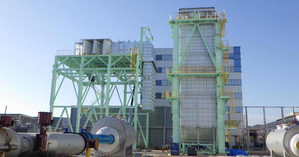
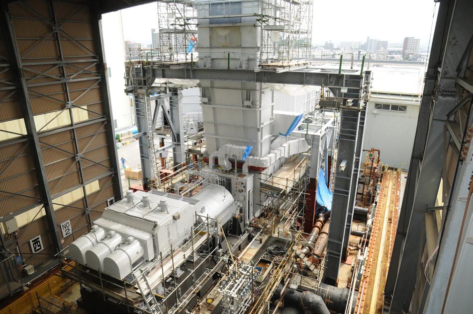
The test bench features shop air filters and ducts as permanent installations, while the gas turbine enclosure and ventilation system can be utilised for both string test and gas turbine solo mechanical running tests. These shop items help to minimise total lead time.
To keep noise levels within limits, the test bench includes silencers in gas turbine intake and exhaust ducts, sound insulation on piping, and soundproof walls surrounding the test bench.
The test bench is designed to allow both top and bottom compressor nozzle orientation through the installation of a gas turbine and compressor string on cement-filled steel blocks. These are then analysed in rotor dynamic calculation models to have enough support rigidity.
Compressor test gas will be carbon dioxide, nitrogen, or other options based on conditions, depending on the site compressor gas property. Compressor test piping consists of a closed loop with gas coolers. High-pressure gas coolers are permanently installed next to the test bench to be used with minor modifications on test gas piping arrangements, based on the configuration.
MCO leverages measurement systems equipped with test bench to evaluate gas turbine and compressor mechanical performance in real time – including temperature monitoring and vibration analysis.
The company also has string test capabilities for motor-driven compressor strings. Depending on the electric power specifications, MCO can apply job electric equipment such as motor, variable frequency drive, and transformer. It has also performed full-load string tests for 37 MW motor compressor strings.
A modularised approach
As the desire for modulisation in LNG plant designs and construction takes centre stage, MCO’s new Mitsubishi Compressor Smart Packaging (MPAC) design for compressors provides a modularised approach to reduce site work, lower labour costs, and limit nonconformities.
MPAC is applicable for motor-driven packages ranging up to 20 MW and under investigation to expand to the 30 MW class, while taking design parameters into account – such as string configuration.
The design benefits the contractor through a reduction in the number of installed items due to the integrated single skid. This allows for a total footprint reduction, along with lower installation and commissioning fees. MPAC is designed for a skid-mounted equipment arrangement where the main components, such as the compressor, drive motor, gear, lube oil (LO) console, and gas seal module (GSM), are integrated as a single skid. Packaging work on the skid is completed before shipment as long as physically allowed and site work can then be reduced. The main component is arranged on a single skid, allowing the shipment of the compressor package after completion of oil flushing, thus shortening the oil flushing duration on site by several weeks depending on the system arrangement.
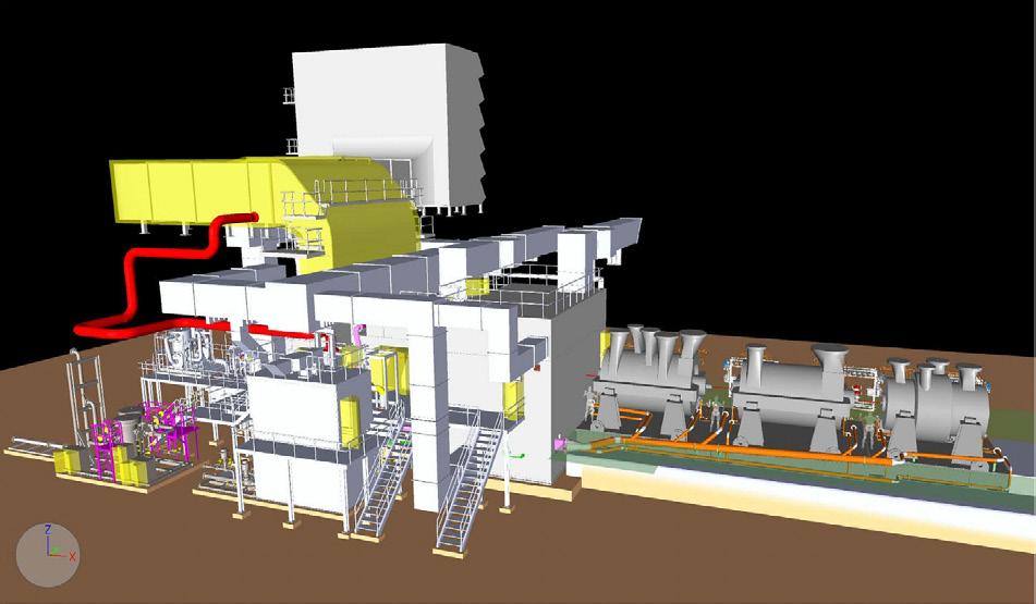
In order to install major equipment on a skid mount with limited space, MPAC incorporates both the LO system and the GSM.
z The LO system: The LO tank is integrated to the baseplate by bolts to accomplish a compact single skid
36 July 2023
Figure 1. Single string H-100 in APCI C3MR process.
Figure 2. MR LP compressor – gas turbine string on test stand in Indonesia.
Figure 3. H-100 test bench under construction.
BRINGING EDUCATION AND INDUSTRY TOGETHER.
SHORT COURSES: SEPTEMBER 25, 2023


SYMPOSIA: SEPTEMBER 26 – 28, 2023

GEORGE R. BROWN CONVENTION CENTER • HOUSTON, TX
The Turbomachinery & Pump Symposia is recognized worldwide as the industry’s must-attend event. Connect with more than 4,750 delegates, meet with leading suppliers, observe product demos, and get answers to your technical questions. We look forward to seeing you in Houston!

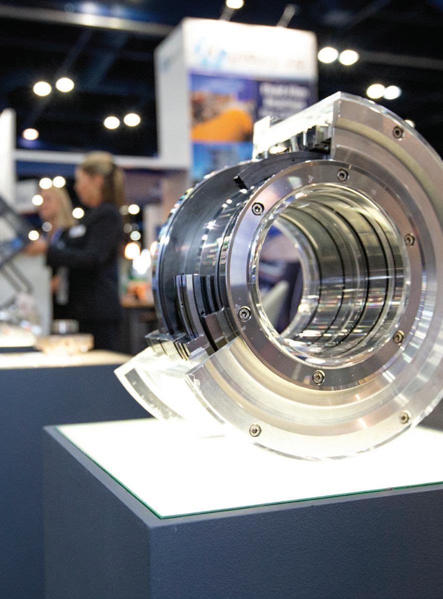
4,750 ATTENDEES
365 EXHIBITING COMPANIES


45 COUNTRIES
TPS.TAMU.EDU


#TPS2023
HOSTED BY
design. This arrangement eliminates drain header piping, and minimises the drain piping from the compressor to the LO tank. Centrifugal pumps are used in MPAC to minimise required components, which do not necessitate safety valves and spill-back pressure control valves at the downstream of the pump. In addition, MCO applies both a plate cooler and an emergency oil pump, which can be installed on the LO tank depending on owner/contractor preference.
z The GSM: The GSM incorporates orifice control for the primary seal gas supply line instead of differential pressure control. By doing so, a minimum footprint is achieved without compromising the required function of the seal gas control system. Interconnecting piping between the compressor and GSM runs low level on the compressor baseplate, while utilising the bottom space of compressor casing. This unique piping arrangement allows for additional space for operability and maintenance.
MPAC delivers an optimised layout for site operations and maintenance work after the plant is in operation. The company utilises its technical expertise to further investigate the operability and maintainability of skid components through 3D review.
Through MCO-I’s Houston facility, MPAC can also be packaged while utilising MCO-I’s compressor mechanical running test. With no sea shipments required, customers can take advantage of MPAC’s uniquely designed package, suitable for inland trailer transportation.
Decarbonising LNG plants
As the original equipment manufacturer, MCO has introduced hybrid combined cycle (HCC) for decarbonisation in an LNG plant. HCC is a system for reducing the carbon footprint through the recovery of thermal energy.
The HCC LNG concept incorporates heat recovery that is used for both power block gas turbines and main refrigeration gas compressors drive gas turbines in LNG plants.
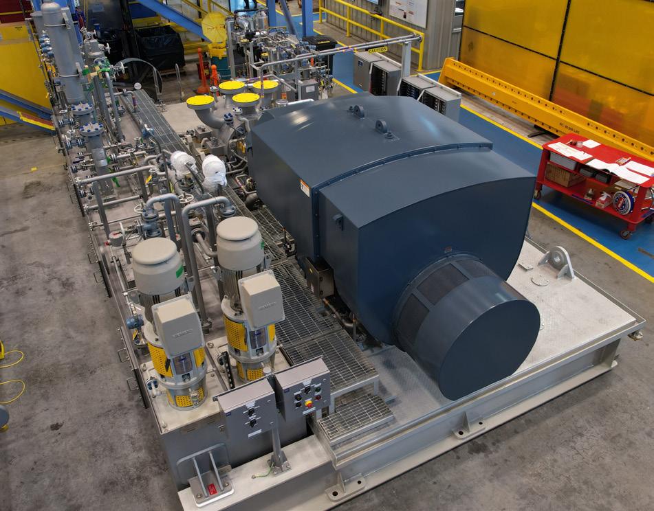
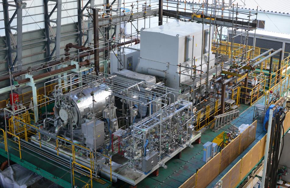
In Figure 6, the refrigeration gas compression system shown in the green box area is independent from the power block gas turbines in the blue box area. The generated steam from the main refrigeration compressor drive gas turbines is used for operating another main refrigeration compressor.
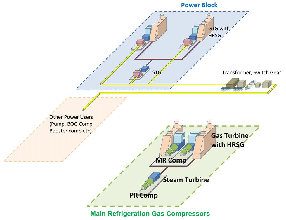
In the HCC LNG concept, energy transmission loss from the power grid to main refrigeration gas compressors is minimised, when compared to e-motor drive main refrigeration gas compressors sourced by power grids. The HCC concept, which can be integrated with additional technologies, such as carbon capture and storage or hydrogen combustion, can provide significant advantages on improving thermal efficiency, boosting capacity and reducing carbon intensity per tonne of LNG produced.
Conclusion
MCO has provided main refrigeration compressors and other compressors in LNG projects on a global front. The company strives to maximise overall plant efficiency and LNG production while meeting market demands for significant reductions in CAPEX and OPEX, shorter delivery and site construction times, and lowered carbon emissions.
MCO has load string test capabilities for both gas turbine-driven and motor-driven compressor strings for confirming system reliability before shipment.
MCO’s new MPAC design for compressors provides a modularised approach to reduce site work, lower labour costs and limit nonconformities while the HCC LNG concept can provide significant advantages on improving thermal efficiency, boosting capacity and reducing carbon intensity per tonne of LNG produced.
38 July 2023
Figure 4. Compressor for pipeline – 37 MW motor-compressor string on test stand in Norway.
Figure 5. Compressor-applied Mitsubishi Compressor Smart Packaging concept in the Gulf Coast.
Figure 6. Simple schematic of hybrid combined cycle LNG.
Catherine Austin, I-Tech, Sweden, explains how to tackle the problem of barnacle biofouling for both the LNG-powered fleet and LNG carriers.

39
Newbuild LNG carrier orders have been growing rapidly as Qatar prepares for its massive expansion of production, and other emerging nations seek to fulfil the growing import demand for LNG from Europe, Japan, and China.
By mid-2022, orders for large LNG carriers (exceeding 140 000 m3) were the highest in 22 years according to Clarksons. As of mid-May, a total of 26 new LNG carrier orders have been placed in 2023 – most of which have been booked with Korean shipyards.
This is great news for Korean shipyards. However, there is a significant challenge for ship builders during the outfitting period of LNG carriers in yards located in warmer waters, such as those off the coast of South Korea: biofouling.
Beware of the barnacles

For both the LNG-powered fleet and the LNG-carrying fleet, managing the effect of hull biofouling on vessel performance when a vessel is in active service is a significant challenge. If these vessels pick up biofouling on their hulls and in niche areas, it can be very detrimental to bunker fuel consumption if operating on a fixed speed. Alternatively, if a vessel is operating on a fixed shaft power, it will suffer speed losses.
LNG carriers in particular predominantly spend long periods of time in waters with a high intensity of biofouling organisms. Once in active service, their typical trading routes are through warmer waters posing a high biofouling risk. LNG carriers also spend periods of time static in high risk biofouling hotspots off the west coast of Africa, the Middle East, Southeast Asia, and Australia during gas up and cooldown periods necessary when loading the cargo, which increases their biofouling risk significantly.
However, the type of biofouling that accumulates on the hull can determine the severity of the fuel penalty. Hard fouling species exert the greatest negative influence on bunker fuel consumption and can create a higher level of speed penalties when a vessel is in service. This is because hard-shelled species attached to the hull create greater hydrodynamic drag compared to soft fouling marine species.
Although barnacle fouling can only occur when a ship is idle or operating at low speeds, as soon as larvae have the chance to attach, they glue themselves to the surface and create a calciferous bottom plate using one of the strongest glues in nature. From this glued baseplate, they build up walls around their soft body to form a volcano-shape shell.
However, it is not just when vessels are idle in or around ports during their day-to-day operations that they are exposed to the risk of accumulating barnacle biofouling on the hull. It is a problem that is extremely prevalent in shipyards, particularly for vessels with long outfitting periods, such as LNG carriers.

Barnacle fouling risk at shipyards
The risk of newbuildings suffering intense fouling during their long outfitting periods is high, particularly in shipyards located in warmer waters.
For LNG carriers, the outfitting period is much longer than many other vessel types due to their complexity. In fact, the fitting out period after launch can be in excess of 12 – 18 months, compared to just a few months for bulkers, container vessels, and tankers.
During the outfitting period, a significant area of the underwater hull and niche areas are exposed to biofouling species. Here barnacles are enemy number one, with some newbuild ships leaving the shipyard for sea trials with troublesome calcareous barnacle fouling that plays havoc with vessel speed performance during sea trials.
This means that vessels being built in regions of the world where shipyards are located in warmer waters, for example, the coastal waters around major South Korean yards, responsible for constructing the majority of large LNG carrier vessels, are effectively barnacle magnets.
One might think that a vessel that has a good antifouling coating applied at the newbuild stage is already protected.
It is well-known that liquid antifouling coatings are used across the majority of the global shipping fleet for the purposes of biofouling prevention. So, it would be entirely sensible to think that the in-situ antifouling coating that was
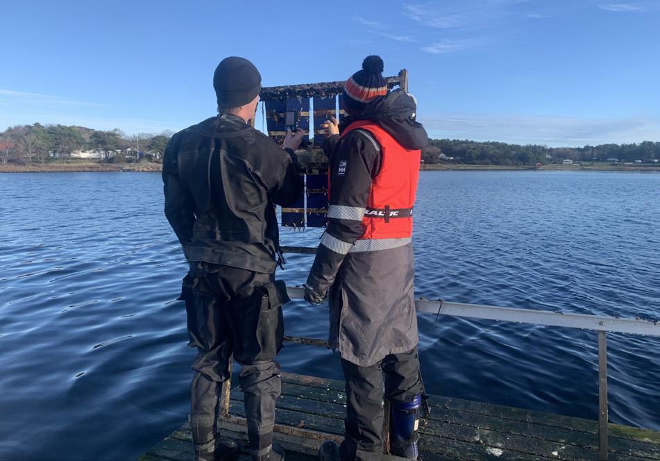
40 July 2023
Figure 1. Close up of a barnacle.
Figure 2. I-Tech R&D chemists inspecting panel tests.
Figure 3. I-Tech scientists remain at the forefront of antifouling R&D.
applied before the vessel was floated would already be working to protect the newbuild LNG carrier’s hull from biofouling. But this is often not the case.
This is due to the antifouling coatings that are applied on a newbuild that are designed to last for 60-months, or more in the case of ocean-going vessels, are intended to protect the vessel when it is sailing. As such, they are designed to work under dynamic conditions. The complex chemistries and biocide release mechanisms (or slippery surface in the case of foul release coatings) behind these coatings do not work so well when a vessel is static for extended periods, particularly when a vessel is sat idle for months at a time. For example, biocidal coatings used on 95%+ merchant vessels are designed to dissolve or ‘polish’ away over time, delivering the biocide when water flows across the hull surface.
Without the flow of water, those coatings are likely not able to offer the superior hard fouling prevention performance required for long static conditions in warmer waters with high concentrations of biofouling species.
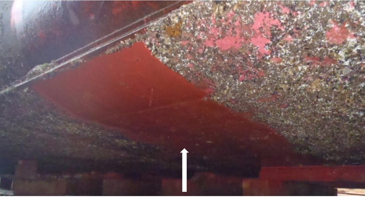
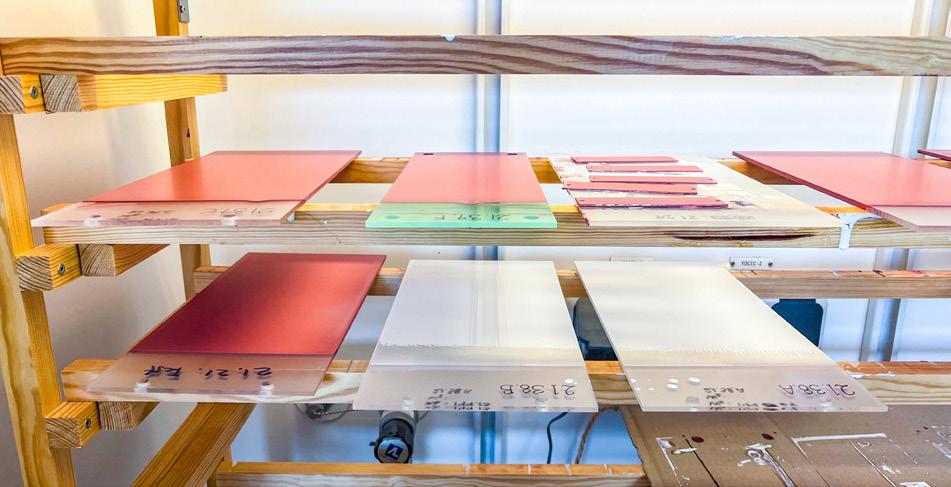
Therefore, if a vessel does not have adequate protection from an antifouling coating layer that can release biocide with little or no water flow, when the vessel goes for its speed trial, the hull may be full of biofouling and the speed trial is affected – the vessel cannot be delivered with biofouling on the hull.
This is a significant challenge for shipyards, particularly those located in warmer waters. The vessel needs to undergo speed trials and be delivered to the owner with a foul-free hull.
Cleaning the hull before the speed trial and delivery to the owner is one option; however, cleaning practices can deplete the thickness of the antifouling system. This is not ideal since liquid antifouling coatings are applied to a specific thickness related to the specifics of the vessel’s operations, such as design speed and activity. Therefore, losing layers of antifouling coating will shorten the performance life of that coating.
Also, for vessels with barnacle fouling, more abrasive cleaning techniques are required. Therefore, undertaking cleaning to remove established barnacle fouling could pose a risk of significant damage to the coating where areas of the coating are left exposed to biofouling more than others. This can be the case when barnacle fouling is partially removed but the barnacles calciferous base plate remains attached to the vessel hull where biofouling can flourish.
How to beat the barnacle
Biofouling control protection for vessels that have long outfitting periods requires further protection in the form of an extra protective layer of antifouling coating, applied as a final layer.
The type of antifouling coating used for this purpose would have the characteristics of a high polishing rate so that biocide would be continuously released when in static conditions, without the need for the flow of water to polish away coating layers exposing fresh biocide.
This additional layer is designed to protect against fouling during the entire outfitting period. By the end of this period, the one layer coating should be almost polished away in its entirety, exposing the main antifouling system for when the vessel enters service.
For barnacle fouling prevention, the antifouling technology Selektope® is now used in many products intended for outfitting biofouling prevention. This is due to its
highly-selective precision, efficiency at extremely low concentrations and sustained performance under static conditions. For this reason, it is being adopted by many of antifouling coating manufacturers as a technology that acts as barnacle fouling insurance.
Selektope protects the hull in long static periods during outfitting, but also, when included in the 60-month antifouling coatings, provides insurance that a vessel can idle for long periods of time without suffering the negative consequences of barnacle fouling – which is very important for LNG carriers and their trade patterns.
Selektope is an organic, non-metal active agent that prevents barnacle fouling by temporarily activating the swimming behaviour of barnacle cyprid larvae, repelling them from the hull surface. As it is an organic compound, it is metabolised by the barnacle larvae, and they return to normal function after a few hours.
This first-of-its-kind antifouling technology caught the attention of coatings suppliers in the early stages of its research and development. To-date, several products have been launched onto the market and the number of Selektope-containing coatings being sold by different manufacturers is increasing y/y. Selektope is playing a vital role at shipyards to protect LNG carrier hulls from barnacle fouling during extended outfitting periods. As such the use of the technology in this application has significantly expanded in the past five years.
Conclusion
Antifouling coatings provide the first line of defence against biofouling. Companies, such as I-Tech, are constantly evolving to meet changing biofouling risk; this includes within shipyards, where Selektope (as a relatively new technology) is increasingly used to protect vessels against barnacle fouling.
July 2023 41
Figure 4. Painted test panels drying for testing in the Mediterranean and Swedish west coast.
Figure 5. Arrow pointing to where Selektope® has been used.

42
In less than a decade, vessel operators must optimise asset performance to reduce carbon emissions by enough to comply with tightening regulatory regimes. As a result, the existing LNG carrier fleet will need to adopt highly effective energy efficiency measures as a means to improve both compliance and performance.
According to recent analysis by classification society Lloyd’s Register (LR), most older LNG carriers, as well as those with dual fuel diesel-electric propulsion, are likely to fall into the lowest categories under the International Maritime Organization’s (IMO) Carbon Intensity Index (CII). These carriers will therefore fare badly in initial CII ratings even before the regulation is reviewed and tightened in a few years.
Among the energy efficiency measures that operators can adopt is a new generation of advanced marine coatings that use cutting edge technology to deliver dramatic efficiency gains. The power savings that can be delivered by PPG SIGMAGLIDE® 2390 can provide speed loss performance of less than 1% and up to 35% reduction in carbon dioxide emissions in comparison to traditional antifouling coatings.
Regulation and compliance

The regulatory landscape facing LNG carrier owners has become more complex with the introduction of the Energy Efficiency Existing Ship Index (EEXI) and the CII.
The EEXI is principally a design process for measuring carbon intensity for all ships above 400 gross t and has been in effect since January 2023. As a one-off measure, compliance is possible using energy efficiency measures and technologies including advanced marine coatings and technical measures, such as limitation of power on the propeller shaft.
The CII meanwhile is an operational measure for calibrating actual carbon intensity of all ships above 5000 gt from January 2023. CII assigns an energy efficiency rating to all ships and calls for a continuous reduction in carbon intensity and therefore progressive improvement in achieved rating. CII is also designed to be achievable with energy efficiency technologies and operational measures including application of the Ship Energy Efficiency Management Plan.
These measures are not the end of the story. The shipping industry is subject to continuously evolving regulation and the IMO measures currently in force will soon be subject to review, while new regulations are also being discussed.
The IMO is continuing to debate the introduction of a global market-based measure that will effectively put a price on carbon emissions in the shipping sector. This may be accompanied by a change in how IMO calculates the intensity of vessel carbon emissions, from the current well-to-tank basis to one that accounts for emissions across the fuel’s entire lifecycle (well-to-wake).
In addition, voyages to and from the EU will be subject to the EU Emissions Trading System from 2024, which will put a price on ship and fleet carbon emissions. The EU’s other main regulatory instrument is FuelEU Maritime, which will be in force from 2025. This includes a well-to-wake greenhouse gas (GHG) intensity requirement with the goal of increasing the use of low and ultimately carbon-neutral fuel by the maritime industry.
These regulations will continue to tighten the parameters under which LNG carriers can operate in compliance, calling for both lower carbon emissions and a higher degree of efficiency.
43
The LNG carrier fleet must implement energy efficiency measures to meet global and regional regulations, says Ariana Psomas, PPG Segment Director, Protective and Marine Coatings.
Existing and planned IMO measures – and in time the EU rules – will force LNG carrier owners to spend additional sums to bring their vessel up to compliance specifications.
Fleet evolution
The majority of ships in today’s existing LNG fleet are unlikely to meet CII requirements from 2025 onwards, according to a recent analysis by LR.
LR estimates there are approximately 250 steam turbine powered vessels designed to use boil-off gas (BOG) for propulsion. Their propulsion arrangements are focused less on efficiency and more on the productive consumption of BOG.
Boilers coupled with steam turbines appear a good match despite their efficiency being marginally over 30% or even lower, when beyond the optimum operating point which would be close to slow steaming conditions.
The next iteration of LNG ship design moved from steam to four-stroke, dual, or tri-fuel diesel-electric
propulsion systems, using conventional marine fuels or LNG. These vessels have lower boil-off rates, smaller engines, and better efficiency.
The latest generation of two-stroke powered LNG vessels have even lower boil-off rates, with efficiency at or marginally below 50%. These vessels are equipped with reliquefaction plants on board to convert excess BOG back into liquid cargo, conserving the value of the delivered cargo. There are approximately 210 of these ships in operation today, making up the balance of the fleet.
The first two generations of vessels ship categories – well over half of the existing fleet – are unlikely to achieve CII ratings of A, B, or C, according to LR analysis. This means that ships rated E will have to undergo carbon-efficiency improvements immediately, and owners of D-rated vessels will have to ensure that ships become more fuel efficient within coming years.
However, since CII assessments will become progressively stricter from 2027 until the end of the decade, ships which are adapted to meet CII requirements by 2024/2025 may subsequently fall into categories D and E later in the decade. Owners of these older vessels will then be faced with the decision over whether to invest in sustainability measures, or sell them for conversion or recycling.
This also suggests that more slow steaming is likely as operators look to conserve fuel and meet CII compliance targets, a measure that will also drive demand for more tonnage. According to data from Clarksons Research, a one-knot reduction in speed taken to cut emissions across the fleet would also generate demand for between 30 – 40 new ships. Spare shipyard capacity could prove a constraint on further orders, applying further pressure on owners to invest in the efficiency of existing ships.
Coating contribution
As the latest addition to the PPG Sigmaglide range that has been widely used by many vessel owners and operators worldwide for more than 30 years, PPG Sigmaglide 2390 represents a breakthrough in vessel efficiency and performance.
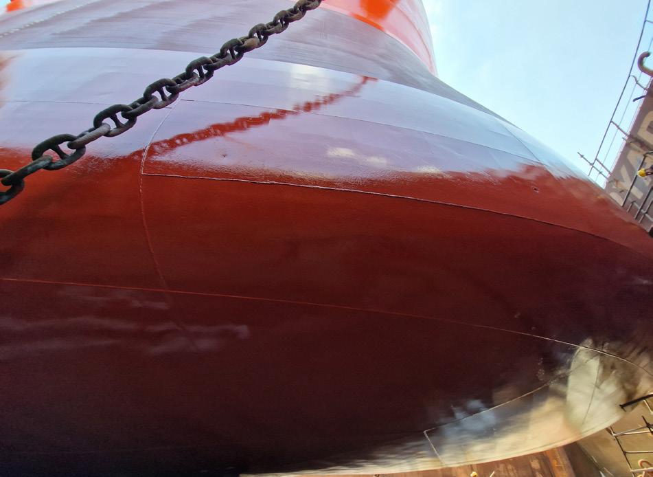
This durable and long-lasting biocide-free fouling release coating has been proven to improve performance and reduce carbon impact. These significant performance benefits are achieved thanks to the incorporation of PPG’s HydroResetTM technology into the 100% pure silicone binder formulation.
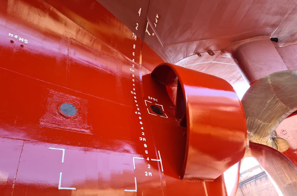
When PPG Sigmaglide 2390 is immersed in water, the PPG HydroReset technology senses the presence of water molecules and instantly reorganises the surface profile of the coating at a nano scale to generate a super-smooth, ultra-low friction surface.
This creates a highly effective, almost friction-free, non-stick surface that marine organisms do not recognise and cannot adhere to, resulting in a fouling control performance that delivers up to 150 days of idle performance.
This fouling control performance is achieved with no release of biocides into the oceans, thus safeguarding the company’s commitment to a sustainable future.
In addition to the increase in idle time, the ultra-smooth surface of
44 July 2023
Ship type Years of operation Average sailing speed Average sea temperature Operational rate Average speed loss LNG 145 000 m3 4.5 15.0 kn 24.7˚C 70.7% 0.9% LNG 145 000 m3 3.5 15.0 kn 24.9˚C 82% 0.4% LNG 145 000 m3 4.0 14.6 kn 25.2˚C 87.2% 1%
Table 1. Average speed loss for LNG carriers by years of operation
Figure 2. SIGMAGLIDE 2390 has been proven to improve performance and reduce carbon impact.
Figure 1. Fouling control performance is achieved with no release of biocides into the oceans, providing a sustainable solution.
PPG SIGMAGLIDE 2390 results in immediate power savings and carbon reductions.
Achieving compliance
As a leader in marine coatings technology, PPG co-operates with the industry’s leading technical institutes to perform performance predictions for its customers, such as using computational fluid dynamics to analyse the performance of vessels coated with different coatings systems and technologies, as well as monitoring subsequent vessel performance.
The company’s customers are already benefitting from these services and from the data-proven expertise that PPG is offering to take informed decisions on coating system selections and maintenance to ensure the optimal performance of their vessels is achieved.
Informed and data-driven decisions are particularly important as the new GHG regulations, and compliance with CII and EEXI, require a high level of investment from shipowners. PPG can support the regulation compliance decisions by building vessel specific business cases and performing compliance sensitivity analyses.
In partnership with independent hull efficiency experts, the company has tested the speed loss performance for several LNG carriers using Sigmaglide, following ISO19030 test conditions.
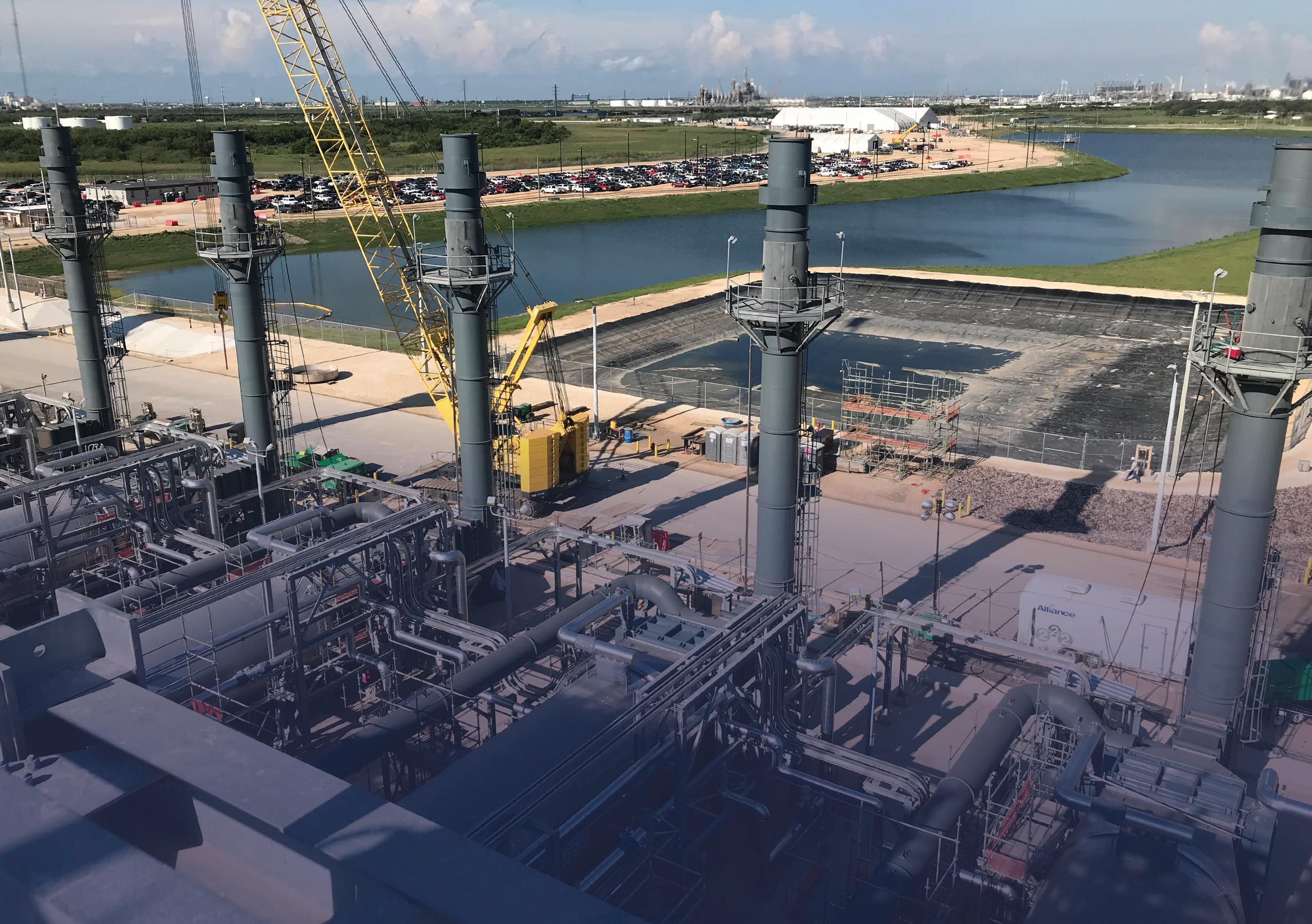
The results consistently show significant speed gain of average 3% as compared to sea trials with premium antifoulings while on the LNG carriers, the speed loss results were consistently below 1% over the testing period.
In independent evaluations, PPG Sigmaglide 2390 was found to have an immediate beneficial effect on frictional resistance with the potential to lower carbon emission by up to 20% through reduced fuel consumption. The coating’s ‘surface effect’ created by PPG’s HydroReset technology and silicone composition has an additional positive effect on speed loss equivalent to a 15% reduction in carbon emissions.
By combining the positive impact of increased fouling resistance and the surface release effect, Sigmaglide 2390 is able to provide a carbon improvement of up to, 35%, equivalent to up to a three-grade improvement in CII rating.
Conclusion
The pressure on the shipping industry to lower fuel consumption and cut carbon emissions is continuing to grow. Regulatory compliance will also become increasingly tough in the coming decade, presenting operational and strategic issues for all ship operators.
For LNG carrier owners, it is a clear that a combination of energy efficiency measures is urgently needed to improve performance by enough to support compliance towards the IMO’s first carbon reduction date of 2030.
Coating solutions, such as PPG’s, have been proven to make a direct contribution towards lower carbon emissions and also provide reliable protection for the marine environment. Updating the hull coating on existing vessels is one of the powerful tools at owner’s disposal to improve performance, lower fuel consumption, and make a substantial contribution towards compliance.
Process Heating Systems Thermal Fluid Heating Systems for the LNG Industry. www.sigmathermal.com

46
JeffAwe,CastAluminumSolutions,USA,providesinsightinto theefficientheatingandvaporisingofnaturalgasandother processmedia.
There are a wide range of applications in the LNG industry that require the heating or vaporising of natural gas, refined methane, process gases, cryogenic gases, and the like. These needs are partially driven by the fact that, over the past 10 – 20 years, there have been tremendous advances in fuel cells, gas turbines, gas purification methods, and approaches to gas distribution. Additionally, consumer demand for comparatively cleaner fuels has helped fund the evolution toward more advanced LNG transports, more sophisticated pipelines, and larger numbers of compressed gas dispensing stations. But the one thing that continues to be steadfastly ‘old school’ are the heaters that tend to go into these applications. This is where Cast Aluminum Solutions (CAS) is looking to change the dynamics around heating natural gas.

Heater developments
The company’s CAST-X Heater has a very different design from a traditional immersion heater, flange heater, or shell and
tube heat exchanger. The design has a much smaller footprint than a traditional immersion heater, which has not changed substantially since 1950.
With most traditional heater designs, the heated media is in direct contact with the heating elements, which are contained within a large pressure vessel. With the CAST-X Heater design, the heated media is isolated in a helically-coiled flow-tube, so heated liquids and gases never contact the heating elements. The 316 stainless steel coil is cast into an aluminium mass, which also contains electric heating elements: this assembly creates the ‘heater body’ of the company’s heater.
A typical CAST-X Heater would then be fitted with thermocouples or RTD temperature sensors. Long thermo-wells within the heater body allow onboard sensors to show the heater’s core operating temperature.
Surface-mounted bi-metal mechanical switches can also be installed, for redundant high-temperature cut off purposes. The largest CAST-X Units will have up to nine heating
47
elements (CE and UL Certified), grouped into three independent circuits. Explosion and moisture-resistant terminal enclosures can be fitted to comply with Class 1 environments/hazardous location installations.
With a CAST-X Heater, there is no ‘pressure vessel’: the stainless steel flow-tube contains the pressure, and most standard CAST-X flow-tubes are rated to at least 3100 psi (215 bar), with many rated to over 5000 psi (350 bar). If higher pressure capacity is required, the heaters can be equipped with custom thick-wall tubes. If caustic impurities not compatible with 316 SST are present in substantial quantities, flow-tubes made of special alloys (such as Monel, Inconel, or Hastelloy) can be substituted into any CAST-X Model.
Many CAST-X Models are available with one or two flow-tubes. Dual tube models allow for innovative flow configurations, including split flow (for low pressure drop in high flow applications) or series flow (where media is plumbed through tube 1 then tube 2, to extend the dwell time).
One of the advantages of using the CAST-X Heater is they are compatible with no or low flow situations (unlike most immersion style heaters). With the heating elements being cast in, they are always in direct contact with the heater body, which prevents element ‘hot-spots’. The heating elements are not ‘out in the open air’ (which, in a traditional immersion heater, often leads to element burnout). So, operators do not have to worry if an operator temporarily cuts the gas flow or accidentally shuts down a valve.
Another advantage is maximum operating temperature. Some of today’s fuel cell applications require very high gas temperatures: this is where CAST-X High Temperature models
are often deployed. These heaters can deliver continuous operating temperatures to 600˚C (1110˚F), with the same levels of safety and efficiency seen in standard CAST-X units. The standard CAST-X will have an aluminium heater body, while the CAST-X High Temp will have a bronze heater body.
For applications requiring a combination of high flows and high temperatures, some customers utilise a standard model as a preheater, and a high temp unit to achieve their final target temp. Controlling these high-performance heaters is not difficult: CAST-X Heaters are compatible with most common control panel formats, including PIDs, PLCs, SCRs, and cascade control systems. CAST-X flow-tubes connect to system lines via standard compression fittings; welded flange style fittings are also an option.
The team at Cast Aluminum Solutions can provide assistance when selecting which CAST-X Model is appropriate for a particular application. Watt calculations can be provided to help customers determine appropriate heater power. The company can also provide pressure drop estimates, to ensure proper flow-tube sizing.
The CAST-X Design, and the various models, have been thoroughly tested and vetted. In addition to experience with thousands of worldwide installs, the company has a robust R&D Lab which is used to test CAST-X Heaters for field survivability (ensuring heating elements and components can handle power surges, maximum operating temperatures, moist conditions, and so on).
Heater design features are matched with market trends. The company’s large network of sales engineers and product distributors – with offices throughout North America, Europe, and Asia – provides feedback on product optimisation ideas and emerging markets (clean hydrogen, for example) which is then funnelled to the CAS New Product Development team. The best ideas are then prototyped, tested, and tweaked at the CAS Research & Development facility. This ‘voice of the customer approach’ was the key driver behind the development of the CAST-X High Temp line, and continues to generate new ideas for product line expansion.
Applications
The company’s heaters are utilised for a variety of natural gas heating and vaporising applications, including many of which involve countering the Joule-Thomson (J-T) effect, or liquid to gas phase change. The stainless steel flow-tubes are compatible with cryogenic temperatures as low as -250˚C (-400˚F), and with the isolated flow-path, media coming into contact with a hot heating element is not a concern.
Natural gas decanting stations
These are a type of pressure reduction station, where the gas typically arrives on site in liquid form. As the gas is unloaded, it depressurises and expands, triggering J-T Cooling. Therefore, a high-pressure circulation heater (such as a CAST-X) must be used to make up for the J-T cooling and icing, assuring the gas stream is within the compressor’s operating parameters.
Natural gas filling stations
Reliable outlet pressures and temperatures are critical in natural gas filling systems; achieving this uniformity is not always easy, considering most fuelling stations are outdoors. In this situation, a CAST-X Heater can be employed and controlled to deliver gas that is consistently above
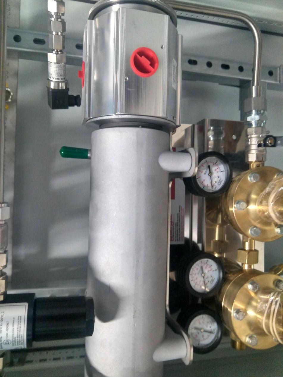
48 July 2023
Figure 1. CAST-X 2000 Heater with certified explosion proof terminal enclosure, installed at a customer location.


NORTH AMERICA A supplement to LNG Industry LNG Industry will be in Vancouver! Visit us at LNG2023 - Booth 804 Distributed at
dew point, eliminating concerns about governing the flow and restricting release.
Gas metering stations
Some climates and pipeline conditions will see strong benefits with the installation of an appropriately-sized CAST-X at the metering station or pressure reduction station, at the point where the gas initially inlets the system. Field metering stations often have minimal crews, and a properly-configured
and controlled ‘set it and forget it’ CAST-X Heater will provide the safe and efficient heat required to alleviate icing and prevent damage to downstream components.
Dry gas seals
With its high-pressure capacity and ability to utilise feedstock gas or bottled gas, CAST-X Heaters are widely used on gas seals for centrifugal compressors. The heater will provide humidity reduction, as well as temperature optimisation. Again, the stainless steel flow-path (where the gas has zero contact with the heating elements) means engineers do not have to worry about contaminants potentially being generated from the heater.
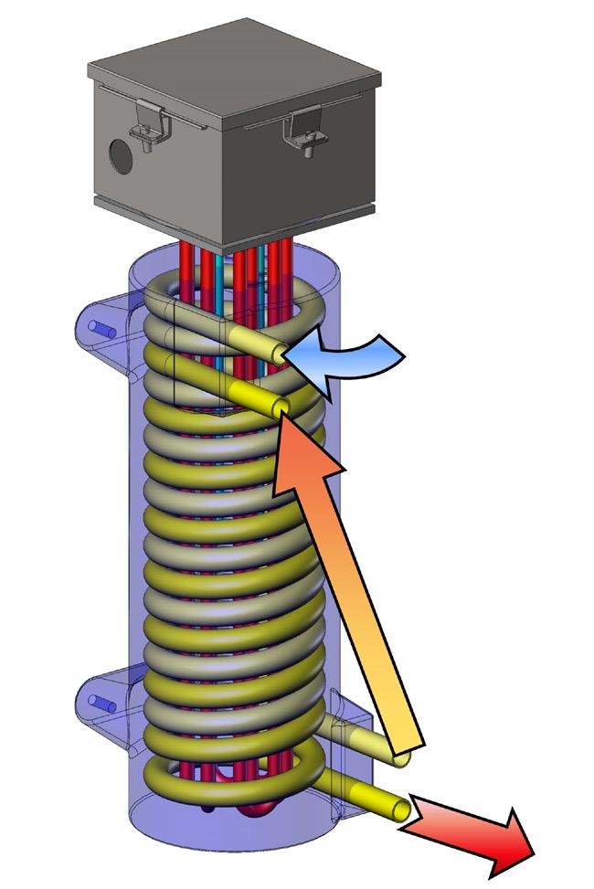
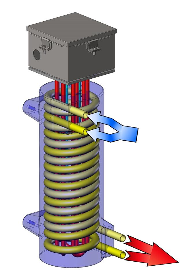
Fuel gas conditioning
For small turbines, CAST-X Heaters are utilised on fuel gas conditioning skids. These skids perform two functions; removing all liquid droplets and solid contaminants from the gas, and adjusting the gas temperature to comply with injection requirements. The proper removal of moisture and solid particles from the gas prior to injection has been shown to improve the operation of rotating components, and enhance overall turbine performance. The quality of the gas (or lack thereof) sometimes requires corrosion-resistant alloys be chosen for CAST-X flow-tube material (and other tubes within the system).
Gas sampling systems
Small CAST-X Heaters (under 10 kW) represent an efficient and effective approach to gasifying small samples of compressed natural gas from large tanks, to test the media for purity, potential contaminants, and moisture content. Tied with appropriate analysis components, smaller-sized models can be easily integrated into portable sampling and test systems.
New fuel cell applications
Over the past three years, Cast Aluminum Solutions has seen a strong increase in fuel cell installations, where CAST-X Heaters are employed to vaporise water, help separate-out the hydrogen in common hydrocarbon molecules, or pre-heat pure hydrogen as a final, finished fuel. Each of these applications requires slightly different temperatures and considerations, but they all relate back to common fuel cell-related uses for standard CAST-X Heaters and CAST-X High Temp Heaters.
These are just a few of the many applications into which CAST-X Heaters can be utilised. They are also widely used to heat and/or vaporise many popular refrigerants and process gases (nitrogen, argon, carbon monoxide, carbon dioxide, helium), as well as warming specialty chemicals for the semiconductor, medical device, food, and
markets.
Conclusion
As the industry continues to evolve – and gas processors seek optimisation opportunities – the CAST-X Heater can be viewed as a tool to help engineers and system designers meet the challenges of today’s LNG and process gas markets. Smaller, safer, and compatible with high pressures, the CAST-X allows those on the front lines of innovation to continue blazing new trails toward a cleaner future. Progress must progress,
they say.
50 July 2023
petrochemical
as
Figure 2. ‘Dual Tube Parallel Flow’ is appropriate for high-flow applications, where the user wants to minimise pressure drop. Y and T fittings can be utilised to split the flow at input, and then bring the two flows back together at output. Some customers will plumb two totally different media chemistries into the inputs, and bring the feeds together at the output.
Figure 3. ‘Dual Tube Series Flow’ is utilised for media that has difficulty absorbing heat, like heavy oils, or gases flowing at very high velocity rates. The company offers tube accessories that connect the output of tube 1 with the input of tube 2 – this series flow configuration extends dwell time, potentially increasing Delta-T.
and micro scale LNG. New projects need cost-effective, rapid construction. The operator that can promise the fast, keenly priced delivery of a new facility will be in a strong place to win these opportunities.


Pipes capable of cryogenic service are an important piece of the LNG infrastructure. For instance, in a typical terminal, the pipes may run 1 km or more from the tank farm to the end of a jetty, particularly in locations with shallow water. To date, metallic pipes have been the industry norm, using cryogenic service alloys such as Stainless Steel 316. Such materials are heavy and require specialist skills for on-site welding and inspection. These activities can be costly and add to the installation management headache since expert teams need to be mobilised. Corrugated-metal hoses are well established for LNG bunkering but are best suited to shorter lengths,

51
Dr Jonathan Wilkins, Enoflex Ltd, UK, details the development journey for a non-metallic, cryogenic pipe technology for use in regasification terminals.
otherwise the corrugations can cause excessive pressure and fluid agitation that generates boil-off gas.
To solve these challenges, Enoflex has industrialised an alternative smooth-bore pipe solution using non-metallic, thermoplastic-composite materials. There are parallels with the oil and gas industry that for some years has used reeled, smooth-bore non-metallic pipes to enable rapid deployments for both on-land and subsea projects. Such oil and gas pipes are based on thermoplastic polymers and are often reinforced with carbon or glass fibres for added strength and stiffness. However, most polymeric materials become brittle at cryogenic temperatures encountered in LNG applications. To solve this fundamental issue, Shell identified and patented single-polymer-composite (SPC) materials as a good candidate that balances strength and toughness at -165˚C. Shell and Enoflex have collaborated in a joint development programme to develop, qualify, and industrialise SPC pipes into a commercial solution for LNG transfer.
The challenge
When starting the development of a new technology, it is important to define the design or economic problems that are not solved by existing products. Based on conversations with LNG operators and EPCI architects, Enoflex identified the following industry needs and mapped them to the desired pipe requirements:
1. Cost-effectiveness: Enabled by a simple product architecture and manufacturing process that minimises
component-count and uses commonly available raw materials. For simplicity, it is preferable to integrate the fluid duct and the structural ‘armour’.
2. Rapid installation: Enabled by ‘haul off’ of a continuous length of pipe from a reel and into a trench or conduit. It requires the product to have sufficient axial strength, balanced with sufficient bending flexibility.
3. Minimal generation of boil-off-gas (BOG): Enabled by a smoothbore product that reduces generation of turbulence within the fluid. It requires the product to minimise flow disturbances, such as corrugations within the fluid path.
4. Reduced on-site fabrication effort and cost: Enabled by transportation of a completed pipe reel from factory to project site, either by road transport for smaller pipes or by ship for larger diameters. It requires the product to take bending strains of the order several percent.
5. Low environmental impact: Enabled by a light-weight product that reduces energy consumption during manufacture and transportation whilst being easily recyclable at the end of life. It requires the product to be made from a single material that does not need costly separation into constituent components at the end of life.
Requirements 1 and 2 are aligned with an industry drive to simplify LNG terminals, for example, by moving to designs which are jetty-less, whereby subsea pipes are used to connect the vessel back to the shore, or by using floating LNG transfer infrastructure. An illustration of a jetty-less concept is shown in Figure 1, courtesy of Shell. Project construction timescales and maintenance costs can be reduced by eliminating the jetty and LNG carriers can remain in deep water without the need for regular dredging or extensive breakwaters.
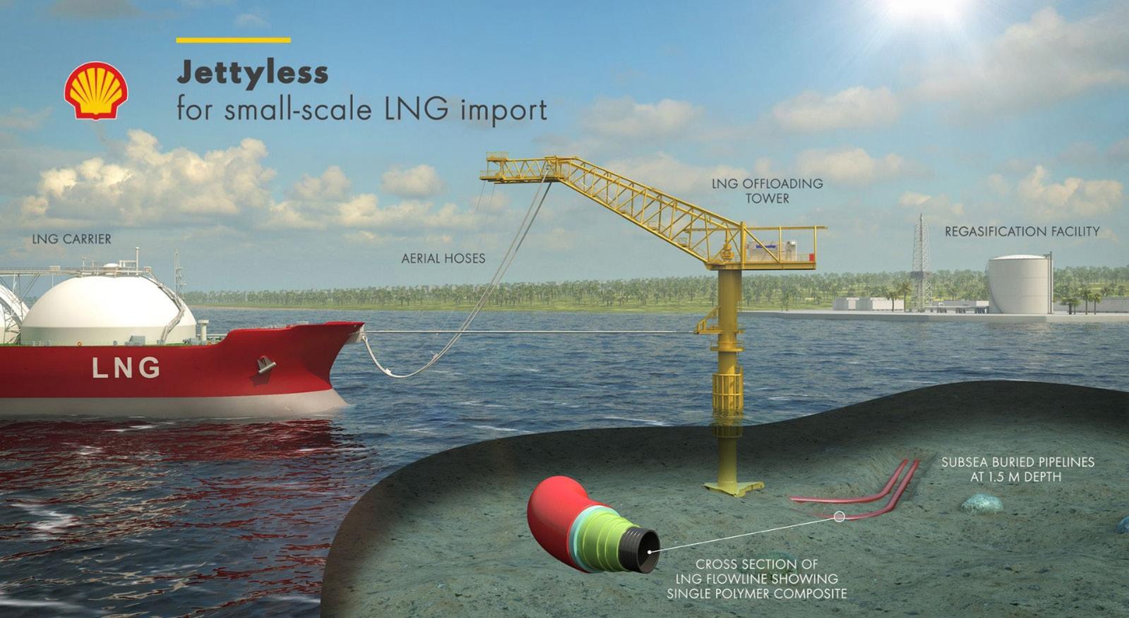
Selecting the right material for the job
In any reeled pipe design, there is a trade-off between the need for bending flexibility whilst maintaining pressure resistance against the internal fluid. The pressures encountered in LNG pipes are high enough, around 20 bar, that an unreinforced plastic extrusion is unlikely to be suitable. Some form of additional reinforcement will be needed. Use of a composite material allows the designer to achieve this within a single, fully bonded component without needing to separate the product into a discrete fluid conduit and a discrete structural armour. This monolithic structure benefits the requirements 1 (cost-effectiveness) and 3 (minimal BOG).
A typical composite material consists of strong and stiff fibres dispersed in a polymer matrix that holds the fibres in place (Figure 2).
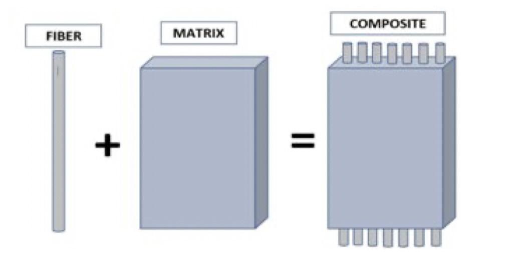
52 July 2023
Figure 2. The fundamental building blocks of a composite material: strong fibres embedded in a supporting matrix.
COMPOSITE
Figure 1. Jetty-less terminal concept showing the subsea pipe. Source: Shell Global Solutions.
FIBER MATRIX
An analogy from the construction industry is steel re-bar inside reinforced concrete. The composite will be an order of magnitude stronger along the fibres, but more compliant in the transverse direction. Composite products, including pipes and pressure vessels, are typically built in an additive manner from individual plies of material. For example, glass-fibre or carbon-fibre reinforced composite pipes have become established in the onshore and offshore oil and gas industry. The designer can adjust the fibre angles in each ply to achieve the desired overall product behaviour. Fibres that are orientated around the pipe circumference will provide pressure resistance. A proportion of other fibres placed close to the pipe axis will provide the balance between axial strength and the bending flexibility needed for requirements 2 and 4 (haul-off and reeled transport).
It is the cryogenic toughness and ductility that differentiates an SPC material from more widely known glass or carbon-fibre composites known in the aerospace, wind, or oil and gas industries. An SPC has fibres and matrix derived from the same thermoplastic material.1 The fibres are drawn and elongated during production to achieve a high level of molecular orientation. This gives a strength that is many times higher than the bulk, unoriented material. Relatively low-cost polyolefin thermoplastics are well suited to this drawing process and strengths in the fibres of around 400 MPa are possible. Since the fibres and matrix polymers are similar, a good microscopic bond exists between the two. This makes an SPC particularly tough when compared to carbon-fibre/epoxy matrix composites found in other industries, for instance. In addition, an SPC product can be disposed of through common thermoplastic recycling routes

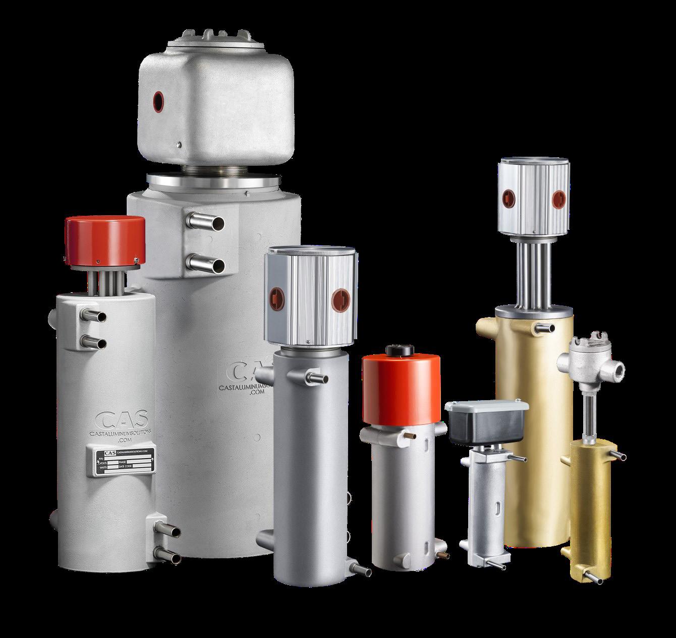
which meets requirement 5 (low environmental impact). There is no need to separate the fibres and matrix from each other, which is a typical problem for other composites. The toughness and recyclability benefits were the original motivation behind the adoption of SPC by the automotive industry several decades ago.
Carbon-fibres are extremely strong; around 1000 MPa or more. Whilst such strengths are necessary in high-temperature, high-pressure deepwater oil and gas pipes, they are less relevant to LNG applications. Rather, it is the cryogenic performance that is more important. SPCs remain ductile at the temperatures encountered in LNG applications, for instance as observed by Atli-Veltin.2 There are several reasons: the comparable coefficients of thermal contraction between chemically similar fibre and matrix, and the strong bonds between the two. Both effects reduce problems with micro-cracking at low temperatures. The molecular orientation within the SPC fibres provides ductility and movement within the material, even at cryogenic conditions. At such temperatures an extruded, unoriented polymer would be well below its glass transition temperature: the point at which the molecules in a polymer appear frozen, brittle and unsuited for structural applications.
The SPC ductility is illustrated in the stress-strain graph in Figure 3, which shows a test to destruction of an SPC material-coupon at around -190˚C, well below the temperature of LNG. Strains of above 10% are achieved and Figure 4 shows a tough, energy-absorbing failure-mode with plenty of broken fibres. By contrast, a bulk thermoplastic found in a typical extrusion would have failed at just 1 or 2%, in a brittle ‘glassy’ manner.
• • PRESSURE CAPACITIES TO 550 BAR / 8000+ PSI • TEMPERATURES TO 600°C / 1110°F
POWER FROM 1 TO 60 KW
•
Building the finished product
Thermoplastic-based composite products can be manufactured without the need for traditional autoclaves, and SPCs are no exception. An SPC pipe can be manufactured in an additive fashion with each ply,
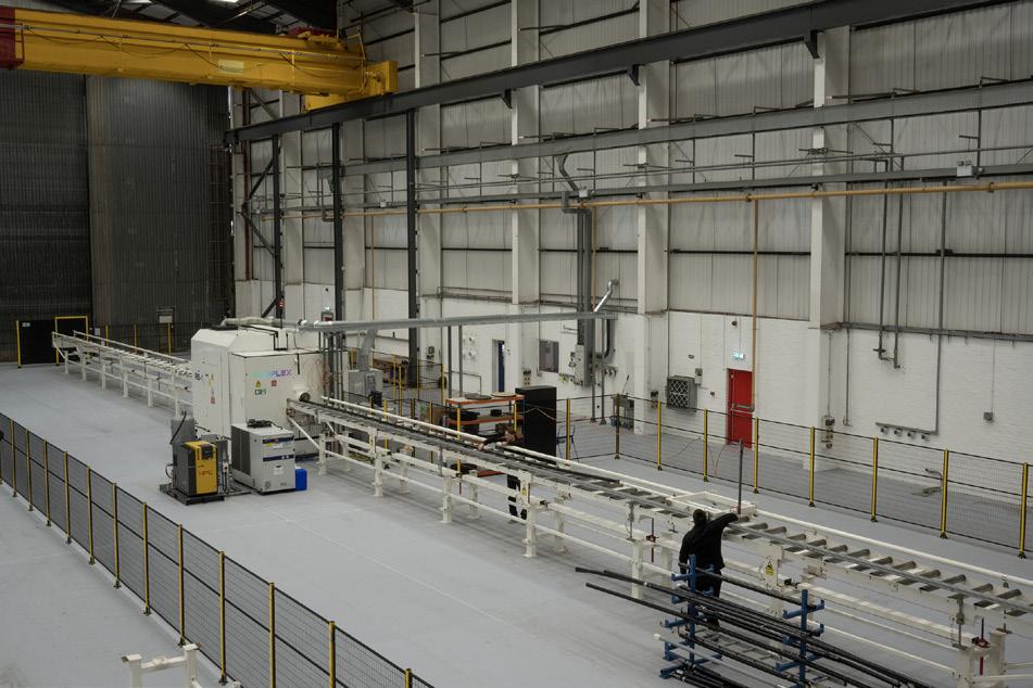
or layer, being fused onto its predecessor. Thus, the body of the pipe grows in layers, akin to an onion skin. Enoflex uses an automated laser-welding process with accurate temperature control. This method was originally developed in the aerospace industry. 3 The thermoplastic skin of each ply of SPC is rapidly heated and melted onto its predecessor substrate. Then the two surfaces solidify together once the heat is removed. The residence time of a piece of SPC material within the welding zone is in the order of a few hundred milliseconds. This fast processing speed, SPC tape customisation, and the accurate temperature control from the laser prevents thermal damage to the SPC fibres. No permanent tooling is required, and so the length and diameter of each pipe can be adjusted for each project. Since an SPC pipe exhibits flexibility, it can be stored and hydro-tested on a reel. As shown in Figure 5, the laser-welding process is clean and requires considerably less energy or water compared to a steel mill.

For LNG applications it is important to avoid an extruded thermoplastic liner to act as a precursor ‘mandrel’ for the first layer of tape. An extruded liner would become brittle at cryogenic temperatures and be the ‘weakest link in the chain’. Instead, the Enoflex pipe is made completely from SPC material. The welds between layers form a fluid-tight barrier. Figure 6 shows a view along the bore of an SPC pipe.
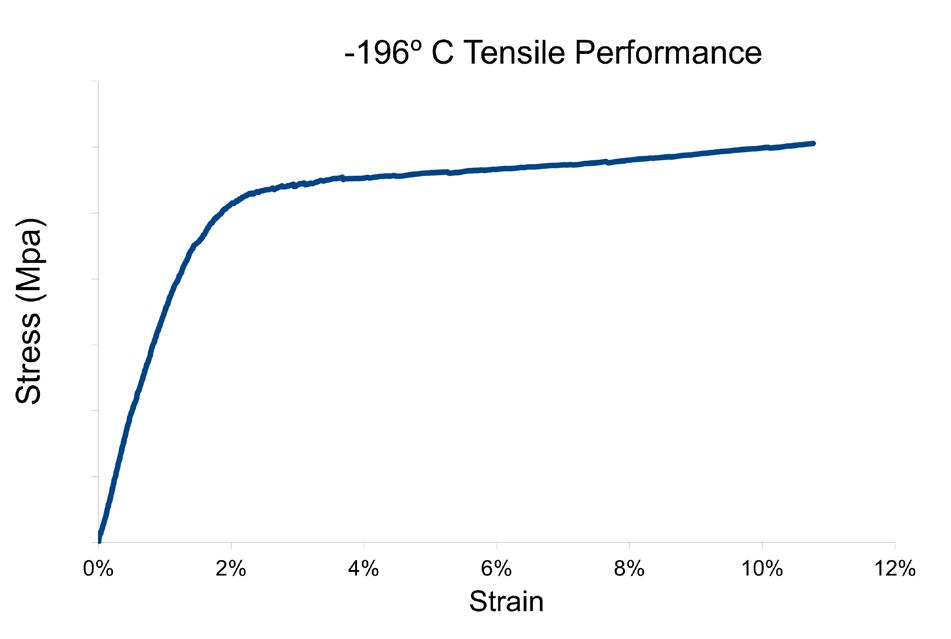
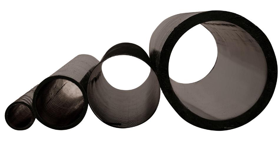
The only metallic components are in the two connectors at either end of the long length of SPC pipe body. These connectors form the interface to the rest of the LNG pipe system, for instance valves or manifolds. The end connectors are fitted to the pipe body within the factory, and can be designed to bolt or weld to the external system in whatever metallurgy choice the customer prefers.
Serving the energy transition
In addition to LNG, other liquified gases are becoming increasingly important to the energy transition: liquified carbon dioxide for non-pipeline transport via ship, the nascent liquid-hydrogen industry, and liquid-nitrogen coolant for superconducting electrification cables. Cost-effective infrastructure is vital to speed the adoption of these new energy vectors.
With such an exciting prospect of new applications and projects, now is the time for the energy industry to consider novel pipe designs. Traditional approaches may not offer the best solution to new requirements. SPC pipes are an important new technology that builds on know-how from the aerospace and oil and gas industries, but with a tailor-made balance of strength and toughness for cryogenic applications. SPC offers a step change reduction for both CAPEX and maintenance costs, and harnesses light weight and low environmental impact as key advantages relative to current stainless steel pipe technology.
References
1. SANTOS, et al., ‘Commercial self-reinforced composites: A comparative study’, Composites Part B, Vol. 223, (2021).
2. ATLI-VELTIN, B., ‘Cryogenic performance of single polymer polypropylene composites’, Cryogenics Journal, Vol. 90, (2018).
CompositesWorld, (2018).
54 July 2023
3. ‘Welding thermoplastic composites’,
Figure 5. An Enoflex laser-welding station contained within a light-proof box. Roller-tracks feed the pipe into the welding station for example from reeling carousels.
Figure 6. A view along the bore of an SPC pipe.
Figure 4. Corresponding cryogenic failure of an SPC material showing plenty of broken fibres, indicative of a tough, energy-absorbing failure.
Figure 3. Typical cryogenic stress-strain performance of an SPC material showing a ‘ductile tail’ to the data.
LNG is a versatile and cost-effective source of energy that is gaining popularity worldwide. LNG is a clear, colourless, non-toxic liquid that is formed when natural gas is cooled to around –162˚C. One of the key challenges with utilising LNG is that it needs to be converted back to a gas form before it can be used as fuel. This is where regasification comes in. Regasification is the process of converting LNG back to its gaseous state, making it suitable for use in homes, industries, and power plants.
Regasification of LNG: A critical step in natural gas transport and utilisation
Regasification of LNG is a critical step in the process of transporting and utilising natural gas as fuel. In order to transport natural gas over long distances, or when pipelines are not available, the gas is commonly converted into LNG through a process known as liquefaction. This involves cooling the gas down to a temperature of approximately -162˚C, which causes it to condense and
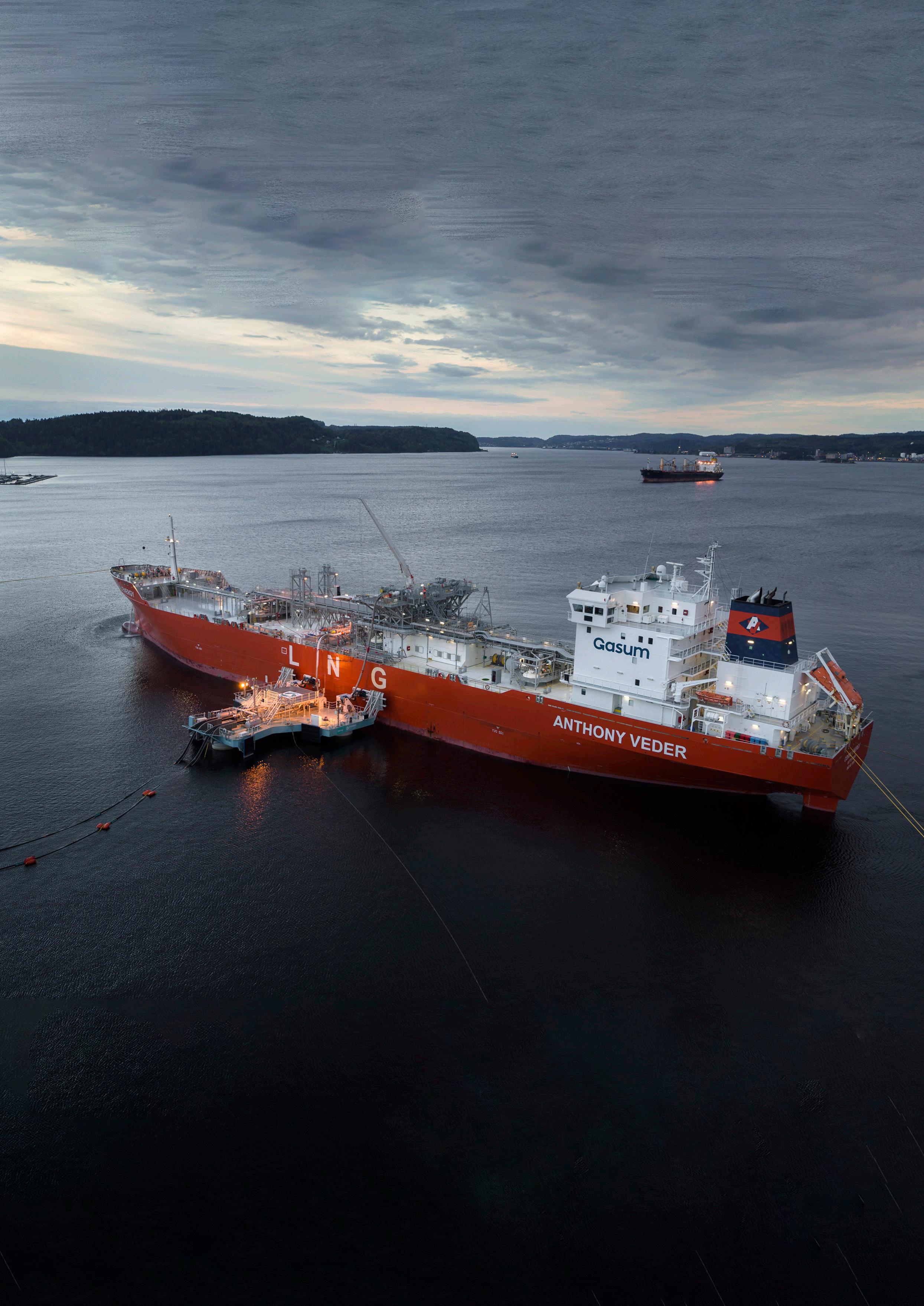
55
ECOnnect Energy examine how LNG regasification technology is evolving to meet the needs of today’s energy market.
become a liquid. This process reduces the volume of the gas by a factor of approximately 600, making it much easier and more cost-effective to transport and store. Once the LNG reaches its destination, it needs to be converted back to its gaseous state through the process of regasification, which involves heating the liquefied gas back up to its boiling point. During this process, the LNG is vaporised, and the resulting gas can then be transported through pipelines or stored for later use. The technology used in LNG regasification is essential for the efficient and reliable transport and use of natural gas, which is an important source of energy for homes, industries, and power plants around the world.
Regasification of LNG typically takes place at large import terminals where LNG carriers discharge their cargo. At these terminals, the LNG is stored in liquid form in tanks until it is ready for use. The regasification process involves converting the LNG back to its gaseous state, which allows it to be transported through a pipeline gas network or by truck, rail, or smaller ships to consumers. This process can also be carried out closer to the end user, where the LNG is transported in its liquid form and then regasified on-site.
The regasification process
The regasification process involves the use of various technologies, including heat exchangers, air vaporisers, and underwater burners, to convert LNG from its liquid to gaseous state. Heat exchangers can use seawater as a heat medium to increase the temperature of the LNG and vaporise it, while air vaporisers rely on large fans to push air through heat exchangers to achieve the same effect.
In periods of high demand, the regasification process can be accelerated by using underwater burners that run on natural gas. These technologies are essential for ensuring the efficient and reliable conversion of LNG from its liquid to gaseous state, which is critical for the use of natural gas as a source of energy.
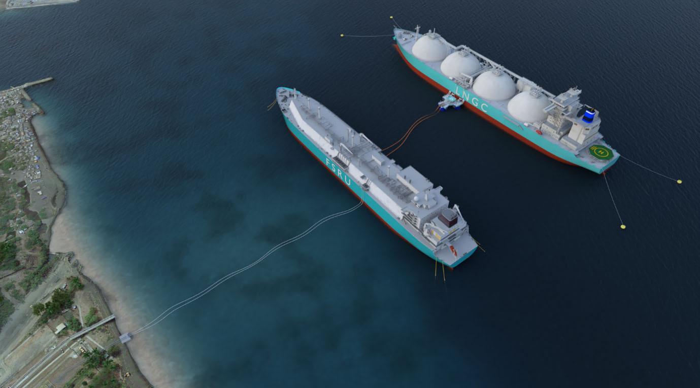
Regasification infrastructure
Regasification infrastructure has traditionally involved transferring gas in its liquid form from LNG carriers to onshore terminals, where the regasification process takes place using onshore technologies. However, floating solutions are becoming more common in recent years. The following sections will explore some of these technologies used in LNG terminals, highlighting their benefits and drawbacks.
Onshore LNG terminals
At an onshore LNG terminal, the LNG is received from a carrier and stored in large onshore tanks before being regasified. Alternatively, an FSU can be used to store the LNG before regasification onshore. Onshore terminals typically comprise berthing facilities, onshore storage tanks, regasification infrastructure, and gas distribution into the domestic network. These terminals are commonly located near power plants or industrial facilities, allowing them to exchange heat and cooling energy to increase overall efficiency.
Air vaporisers and submerged combustion vaporisers are the most common regasification technologies used at onshore terminals. Despite their higher CAPEX when compared to offshore marine terminals, onshore terminals remain the most common terminal configuration due to their ability to accommodate large and small scale LNG import and export. Furthermore, the floating transfer philosophy used in onshore terminals can also be applied to other fluids such as hydrogen, ammonia, and carbon dioxide.
With the increasing demand for LNG in recent years, many companies have started offering innovative solutions to improve the efficiency and reliability of regasification infrastructure. The next section will explore what LNG regasification technology solutions ECOnnect Energy have developed.
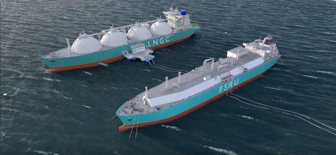
FSRUs
An FSRU is a floating terminal that serves as both storage and regasification facility. It can be a purpose-built unit or a modified LNG carrier. The LNG is regasified, and the high-pressure gas is sent directly into the pipeline.
Alternatively, the storage and regasification functions can be separated into two separate units, the FSU and the FRU. LNG is transferred between the units through pipelines or hoses. This solution can be cheaper than using an FSRU.
ECOnnect Energy provides a solution for transferring high-pressure gas that eliminates the need for fixed infrastructure and is a cheaper alternative if an FSRU needs to be redeployed.
The trend towards floating terminals is on the rise. Constructing an onshore regasification terminal
56 July 2023
Figure 2. An FSRU is a floating terminal that serves as a both storage and regasification facility, and can be purpose-built or a modified LNG carrier.
Figure 1. In recent years, floating solutions are becoming more common to carry out the regasification process.
requires a significant long-term investment and assurance of a steady LNG supply. An FSRU offers a more flexible option as it can be time chartered, converting capital expenses into operational expenses. Moreover, old LNG carriers can be converted into FSRUs, offering short lead times. However, FSRUs have limitations in terms of capacity and lifespan, and, in many cases, an onshore regasification terminal may be more suitable.
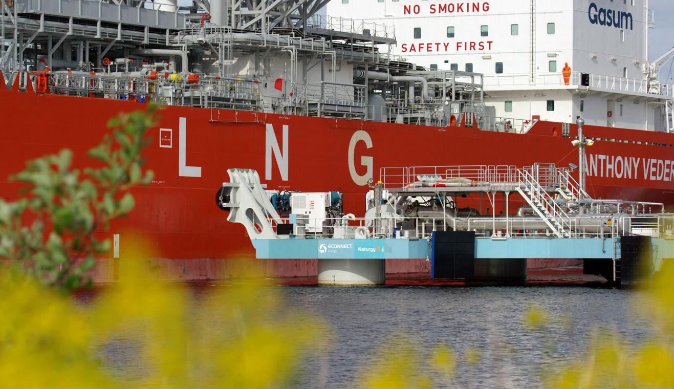
Despite its limitations, the FSRU is gaining popularity due to its reasonable cost and shorter lead time from the final investment decision (FID) to utilisation. As future LNG technology develops, the FSRU is expected to play a crucial role in the industry.
Jettyless technology
The energy import and export landscape is undergoing a transformation with the advent of a new technology called the jettyless transfer system. This innovative solution enables the safe and efficient transfer of fluids such as LNG, ammonia, biofuels, and carbon dioxide (for carbon capture and storage) between a carrier and an offshore or onshore terminal without the need for a jetty.
Compared to the traditional fixed infrastructure of jetties and quays, the jettyless transfer system offers significant cost savings and tremendous environmental benefits as it is prefabricated at a shipyard, eliminating the environmental impacts of constructing a jetty or a quay. Its flexibility and mobility also enable energy distribution to areas that were previously considered infeasible due to high costs or challenging geography.
ECOnnect Energy, a company that believes cleaner energy should be cheap and accessible, provides cost-efficient solutions to clients worldwide. The company offers a distinctive floating technology, powered by its IQuay ® technology. This innovation leaves the marine environment untouched, making it an environmentally friendly and efficient option for energy transfer. The Jettyless IQuay offers a flexible and cost-effective alternative to the construction of jetty facilities, which are often resource-intensive and costly. With this technology, the company aims to simplify project permitting applications and address strict environmental regulations. The technology can be applied to a variety of vessels and terminals, making it ideal for loading and unloading operations, as well as the transfer of fluids, such as LNG, ammonia, CO 2 , hydrogen, and more.
ECOnnect Energy’s IQuay technology offers reduced costs and lead times by avoiding large construction works and simplifying the permitting process. With advanced technology and low operational costs, the IQuay is an ideal solution for environmentally sensitive areas. Additionally, when combined with a floating terminal, power supplies can ramp up quickly and effectively, making it a cost-effective and flexible alternative for a wide range of energy projects.
The IQuay is designed to be a universal interface towards any vessel. With the ability to connect and disconnect in just seconds, the attachment system reduces relative motions between the platform and the vessel. The system’s motions, forces, and holding capacity are continually monitored and interlinked to the ESD system for added safety. Based on technology with over two decades and 700 000 successful mooring operations, the attachment system is both robust and reliable.
The IQuay technology provides a versatile solution that connects to a wide range of vessels, thanks to the vacuum pads that can engage with a flat portion of freeboard below the manifold position. Unlike a fixed jetty, the IQuay platform is floating and follows the carrier with the tide, making it suitable for locations with large tidal variations. The process system on the IQuay is customisable to meet the flow rate requirements of small and large scale carriers, including bunkering capabilities.
The platform is unmanned during operation and is controlled remotely from an onshore control room. All systems are monitored, and operators have a complete overview of the process flow parameters and status of all main systems onboard. The platform deck areas are under complete CCTV coverage, providing the operator onshore with eyes on the platform. Manning is only required during connection to and release from the carrier vessel, and the crew is supplied from the tugboat.
Conclusion
ECOnnect Energy aims the increase the adoption of their low impact jettyless IQuay solutions to effectively protect marine environments, leaving aquatic ecosystems undisturbed. Additionally, incorporating floating and low-impact terminals into energy projects to accelerate the lead time and permit process, saving time and resources. The IQuay transfer solution also offers more flexibility as it is fluid-agnostic, easily transportable, and can be chartered to meet changing market demands. By adopting these innovative solutions, the company can ensure sustainable development while also meeting global energy needs.
July 2023 57
Figure 3. The IQuay technology provides a versatile solution that connects to a wide range of vessels as a result of the vacuum pads that can engage with a flat portion of freeboard below the manifold position.
owadays, businesses have begun to pay more attention to their environment, social, and governance (ESG), looking for ways to reduce their environmental impact, and improve social wellbeing. This is also the case with infrastructure construction, such as LNG terminal and regasification plant.
Background of PTTLNG Nong Fab LNG Terminal II

The PTTLNG Nong Fab LNG Terminal project is located in the industrial zone of Rayong Province, Thailand, and is a joint venture between Taiwan’s CTCI Corporation and Saipem of Italy. Nong Fab is the second LNG receiving terminal invested and constructed locally by PTTLNG Company Limited, a subsidiary of PTT Group, the largest corporation in the country.
The project scope includes two 250 000 m3 LNG storage tanks (the largest capacity per single LNG storage tank in Thailand), an LNG gasification facility of 7.5 million tpy, a 6 km trestle unloading facility (the world’s longest trestle in the LNG field), and an eco-friendly administrative building.
The project was conducted with a focus on ESG factors, ensuring that it meets the highest standards of sustainability. With its emphasis on eco-friendliness, the project has taken steps to mitigate its impact on the environment. Management-wise, its governance structure for the project management reflects transparency and ethical leadership. The project considers the needs of its stakeholders, including the local community, to make certain that it aligns with the values and expectations of those affected by the project. Overall, completion of the LNG terminal project manifests ESG implementation in today’s project
management practice and the positive impact that can be achieved by prioritising sustainability and social responsibility.
Environmentally friendly and coexistent
Enhance environmental circulation on nature detention pond
The PTTLNG Nong Fab Terminal II project preserved and utilised the existing pond nearby the administration building. The pond helps naturally store the rainwater discharge and prevent an adverse impact to the community, as a result of extra rainwater discharge due to the paving change (from green field to concrete).
Meanwhile, by retaining the nature pond, the original ecosystem remains unaltered, maintaining the ecological diversity.
Managing storm water runoff
One of the primary functions of nature detention ponds is to collect and temporarily store storm water runoff from impervious surfaces such as roads, rooftops, and parking lots. This helps to reduce the volume and peak flow of storm water runoff, which in turn can minimise the risk of downstream flooding and erosion.
Mitigating the negative impacts of urbanisation
Urbanisation can disrupt the natural hydrologic cycle by increasing the impervious surfaces and reducing the
58
Chen-Ming Huang, Yun-Chun Lin, and Y. H. Eric Chen, CTCI Corp., Taiwan, outline how the Nong Fab LNG Terminal in Thailand was designed to achieve energy efficiency, environmental care, and community wellbeing.

59
permeable surfaces, such as soil and vegetation. Nature detention ponds help to mitigate these negative impacts by restoring some of the natural hydrologic functions of the landscape.
Maintaining the ecosystem
Nature detention ponds can support a diverse array of plant and animal species, providing habitat for aquatic organisms and enhancing biodiversity. By maintaining the ecosystem, these ponds can help to improve the ecological health of urban and suburban landscapes.
Improving water quality
Storm water runoff can contain pollutants such as suspended solids, nutrients, and pathogens. Nature detention ponds can help to remove these pollutants by allowing them to settle out or by promoting biological processes that break down or assimilate them.
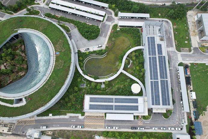
Providing aesthetic and recreational benefits
Nature detention ponds can enhance the visual and aesthetic appeal of urban and suburban landscapes, and provide recreation opportunities, such as birdwatching or walking.
Nature detention ponds serve as important infrastructure for managing storm water runoff, mitigating the negative impacts of urbanisation, and maintaining the valuable ecosystem. They collect and temporarily store storm water runoff, reducing downstream flooding and erosion. They restore natural hydrologic functions and a diverse array of plant and animal species, improving ecological health. They also remove pollutants from storm water runoff, providing aesthetic and recreational benefits. As a result, the terminal has already attracted many community residents to get some rest and relaxation around the nature detention pond.
Sea water outfall tunnel and diffuser pipe
The PTTLNG Nong Fab LNG terminal in Thailand is not only a significant development in the energy sector, but a demonstration of the importance of incorporating ESG considerations into major infrastructure projects. One of the key features of the terminal is its long jetty trestle (up to 5.6 km), which not only prevents construction impact to the livelihood of the fisherman community, but also keeps the nature beach condition unharmed by the trestle construction. This design is made with the goal of reducing the impact on the surrounding environment, while also enabling the terminal to coexist with the local community.
To ensure that the terminal’s operations did not negatively affect the local marine ecosystem, the project team incorporated submerged sea water intake and outfall tunnels into the design. These tunnels were constructed to extract heat from the sea water during the LNG regasification process, resulting in an effluent with a lower temperature than the surrounding environment. This design was based on local Thai environmental regulations and was executed to meet a number of important requirements.
First, the project team was committed to a ‘no dredging’ philosophy, which means they had to ensure that the sea water discharge temperature was consistent with the ambient sea water temperature within a radius of approximately 100 – 200 m from the discharge point.
In addition, the intake temperature of the sea water had to be maintained at a minimum of 21˚C to fit properly with the vaporisers’ design and duty. This meant that cold-water circulation was not an option, as the minimum ambient sea water intake temperature was approximately 24˚C, and no more than -3˚C of recirculation from outfall to intake could be allowed.
These considerations were critical in ensuring that the LNG terminal met its operational objectives and, equally important, upheld environmental and social responsibility principles. By prioritising the ESG considerations into its design and construction, the project team demonstrated that sustainable development is not only possible, but also necessary for large scale infrastructure projects.

Sustainable energy
Cold energy recycling
One of the ways in which the terminal operates in an environmentally-friendly manner is by utilising the cold energy from LNG
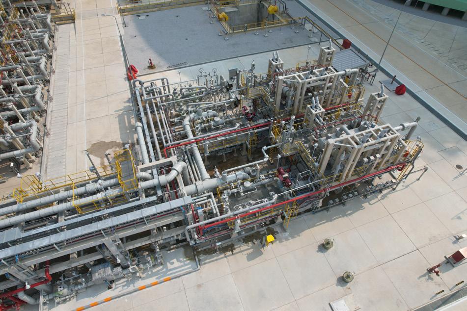
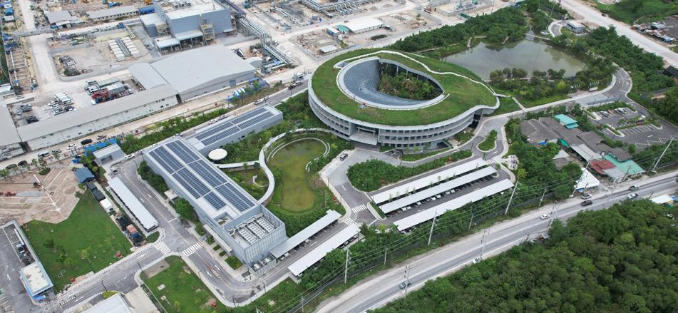
60 July 2023
Figure 1. Administration building
Figure 2. Intermediate fluid vaporisers.
Figure 3. Solar cell on rooftop (left) and wind turbines (right).

Visit our website today: www.globalhydrogenreview.com The home for the latest hydrogen news, analysis and events
for heating, ventilation, and air conditioning (HVAC) and gas turbine generator (GTG) intake air cooling. This approach leads to energy savings of 71 MKWh and a reduction of 37 000 tpy of carbon dioxide.
To implement this approach, the chilled water (CHW) is sent by CHW pumps to intermediate fluid vaporisers (IFV’s) and then routed to the cold energy users. After use, the CHW from the users is routed back to CHW pumps suction side at approximately 10 – 13˚C. This enables the cold energy recovered from the LNG regasification process to be utilised for HVAC in the administration building, as well as for the HVAC for indoor landscaping in the PTTLNG project.
The use of LNG cold energy for HVAC and GTG intake air cooling is an innovative and sustainable solution that helps to reduce energy consumption and minimise the carbon footprint of the project. This successfully demonstrates how companies can implement sustainable practices to meet environmental standards while also improving efficiency and saving costs. By utilising cold energy from LNG, the terminal contributes to a greener and more sustainable future for Thailand and the world.
Green Energy: Solar cell and wind turbine
Environmental protection and green energy are critical issues in today’s world and the key to ESG success. The very first step is to engage everyone, from individuals to enterprises, to reach that aim.
The development of sustainable green energy requires government and enterprise alike to pioneer and guide the direction, and enroot the concept of environmental protection and green energy in each individual’s minds.
Back in the planning and design stage of project, it was agreed that the administration building and shuttle buses need to adopt green energy.
With three sets of wind turbines and the 1400 m2 on-grid solar system, renewable energy is supplied for lighting, HVAC, and a pump in the administration building. Every year, 172 000 KWh of electricity come from wind turbine and 201 000 KWh of electricity come from solar cell.
Environmental aspect
The sustainable energy in use in this project includes solar electricity and wind turbines, suggesting energy supply is renewable and inexhaustible.
Social aspect
Through this project, the concept of implementing green energy to improve the plant environment and reduce carbon emission through adopting sustainable energy from solar and wind is established.
Governance aspect
The energy transition represents one of the greatest technological challenges. In response to this trend, government and enterprise will pay more attention to green energy, with the top priority to reduce energy consumption. It is also necessary to continue developing energy-saving technologies and aim towards the goal of net-zero emissions by 2050.
Open area and public life making
Public spaces and community building are essential components of any city or town. They offer a sense of community and belonging, and promote social interaction, cultural exchange, and economic development. The LNG terminal project recognised the importance of public spaces and community building in its design and construction.
The project was designed to not only produce LNG, but also to provide better living conditions for the community and future generations. To achieve this goal, the administration building was designed as an open area, where people could gather, interact, and enjoy the surrounding landscape. The administration building serves as a popular attraction and has become a symbol of the community.
By creating an open and inviting space, the administration building has helped established a sense of community in the Map Ta Phut area. The area provides an opportunity for social and cultural exchange, promoting a sense of unity and belonging. This plays a vital role in activating the area around Map Ta Phut, contributing to the social and economic development of the community, while strengthening the physical, mental and social well-being of local residents.
Conclusion
The project’s focus on environmental friendliness and community coexistence has resulted in the terminal being able to serve several functions, including: managing storm water runoff, mitigating the negative impacts of urbanisation, maintaining ecosystems, improving water quality, and providing aesthetic and recreational benefits. This project sets an example of how mega-projects can not only focus on their primary objectives, but improve the quality of life for the people and the community.

The inclusion of sea water outfall tunnels and diffuser pipes, with no dredging philosophy and no cold-water circulation, has significantly reduced the project’s environmental impact. The design of the seawater system was based on local Thai environmental regulations, and the design and construction of the seawater intake and outfall tunnels were executed to meet the specified requirements. Furthermore, the project’s sustainable energy practices, such as the use of LNG cold energy for HVAC, have led to environmentally friendly operation.
Overall, the implementation of ESG principles in the PTTLNG Nong Fab Terminal II project has been a significant success, and its practices should serve as a model for future projects in the energy sector. The project’s focus on sustainable and environmentally friendly practices, as well as coexistence with the community, has shown that economic growth and environmental protection can work in harmony.
62 July 2023
Figure 4. Waterfall inside administration building


Hydrocarbon Engineering Online Visit our website today: www.hydrocarbonengineering.com The home for the latest hydrocarbon processing news, analysis, comment and events HE_Website.indd 1 14/08/2018 10:28 Advertiser Page Ariel Corporation 27 Baker Hughes 29 BASF OBC Cast Aluminum Solutions 53 Chart Industries 09 Compressor Controls Corporation 31 Corban Energy Group 13 Global Hydrogen Review 61 Golden Pass LNG 02 Hydrocarbon Engineering 63 Advertiser Page LNG Industry 49 Mitsubishi Heavy Industries Compressor International OFC, 17 NEUMAN & ESSER 33 Nikkiso 07 OPW Clean Energy Solutions 04 Sigma Thermal 45 SPE Offshore Europe Conference & Exhibition IBC Turbomachinery & Pump Symposia 2023 37 Zwick Armaturen GmbH IFC ADINDEX www.lngindustry.com LNG Industry is audited by the Audit Bureau of Circulations (ABC). An audit certificate is available on request from our sales department.
15FACTS
Nepal is the only country in the world that does not have a rectangular-shaped flag.
Thailand received 8.7 million t of LNG in 2022, nearly 43% of Southeast Asia imports that year.
India produces over 20 million tpy of mangoes.
Pakistan relies on gas for one-third of its power generation needs.
The Philippines received its first LNG cargo in April 2023.
The Angkor Wat Temple Complex in Cambodia is the largest religious monument in the world, spanning more than 400 acres.
PACIFIC
Malaysia exported 27.4 million t of LNG in 2022.
South Korea has a separate Valentine’s Day for single people.
The Asia Pacific region is home to 17 megacities, including three of the world’s largest: Tokyo, Delhi, and Shanghai.
Almost three-quarters of Bangladesh’s power is generated from imported LNG.
LNG demand in the Philippines, Cambodia, and Vietnam will be driven by an increasing power demand and transition away from coal.
Imported LNG accounts for around 50% of natural gas consumption in India.
Chinese companies signed around 20 long-term contracts during 2021 alone, accounting for approximately 50% of all contracts signed that year.
Singapore is the only country in the world that has banned chewing gum.
64 July 2023
...ON
Indonesia has the world’s largest number of active volcanoes.
ASIA
5-8 SEPTEMBER 2023, P&J LIVE, ABERDEEN
ACCELERATING THE TRANSITION TO A BETTER ENERGY FUTURE
Connecting you with the offshore energy industry

• Explore new opportunities in the Energy Transition Zone and Theatre, the Hydrogen Hub and the Offshore Wind Theatre
• Find solutions to recruitment and talent evolution in the Future Talent Hub
• Discover the latest technologies within the Innovative Technology Zone

• Attend SPE Keynote and Technical Sessions to learn more about the hottest topics with the industry’s big names
• Meet with world-class exhibitors from across the supply chain in the main exhibition REGISTER NOW offshore-europe.co.uk/lng
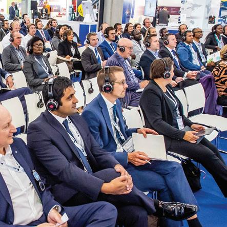
Organised by
Double your impact Reduce your footprint with Durasorb™ Cryo-HRU
This innovative technology combines hydrocarbon removal and dehydration into a single unit to provide natural gas that is ready for liquefaction.

With Durasorb™ Cryo-HRU, your business benefits from:
� Unit designs and simulations from best-in-class modeling tools
� Reduced risk of coldbox freezing and unplanned shutdowns
� Increased profit from reliable operations and long life-time warranties
� Increased operational flexibility and ease of adapting to changing feed gas conditions
� Engineering and technical support for smooth project execution and optimized plant performance
Durasorb™ Cryo-HRU is available as a drop-in retrofit solution or to reduce capital expenditure for a new project.
Find out more today catalysts.basf.com/durasorb
Increasing Mole Fraction Increasing Time Dynamic Regen Profile C6 C7 C8 H2O