January 2025


January 2025
Kunal Sawhney, Kalkine Group, Australia, examines various strategies for decarbonising LNG production, including carbon capture and storage, renewable energy integration, and methane emissions reduction, across major LNG-producing nations.
Pumps and
Justin Hair, Key Account Manager, Sherwin-Williams Protective & Marine, addresses how to shore up specifications to combat corrosion under insulation, safeguard storage tanks, and protect pipelines. 27 Barnacles beware!
Per Svensson, Sales Director, I-Tech AB, outlines the not-so-secret agents protecting the LNG carrier fleet from biofouling.
31 Off the back-foot
Stavros Sklavounos, Hull Performance Solution Manager, Hempel, directs attention towards how companies can get off the back-foot in the race to reduce emissions from LNG carriers.
35 Wise valve selection improves performance
Riyaz Ali, Emerson, USA, explains how a properly specified valve positioner reduces maintenance, increases uptime, and cuts operational costs, especially instrument air consumption.

Mark Naples, Managing Director, Umicore Coating Services, provides insight into how infrared filters can unlock the next level of LNG maintenance.
LNG Industry recently spoke to Adam Prestidge, Executive Vice President and Head of Business Affairs at Glenfarne Energy Transition, about the company’s latest projects and the growing importance of LNG.


Paul Hughes, Project Delivery Vice President, and Andy Loose, Vice President for LNG sector, Worley, detail how an FSRU was operationalised in less than nine months to help secure Germany’s LNG supply and reduce dependency on Russia.
Francesca Serra and Filippo Perricone, HIGAS, Italy, delves into boil-off gas management at small scale LNG terminals.
Sherwin-Williams Protective & Marine delivers world-class industry subject matter expertise, unparalleled technical and specification service, and unmatched regional commercial team support to customers around the globe. The company’s broad portfolio of high-performance coatings and systems excel at combatting corrosion and helps customers achieve smarter, time-tested asset protection. The company serves a wide array of markets across its rapidly growing international distribution footprint, including the energy market where its latest coatings technologies enable greater durability, lower costs, and additional advantages.
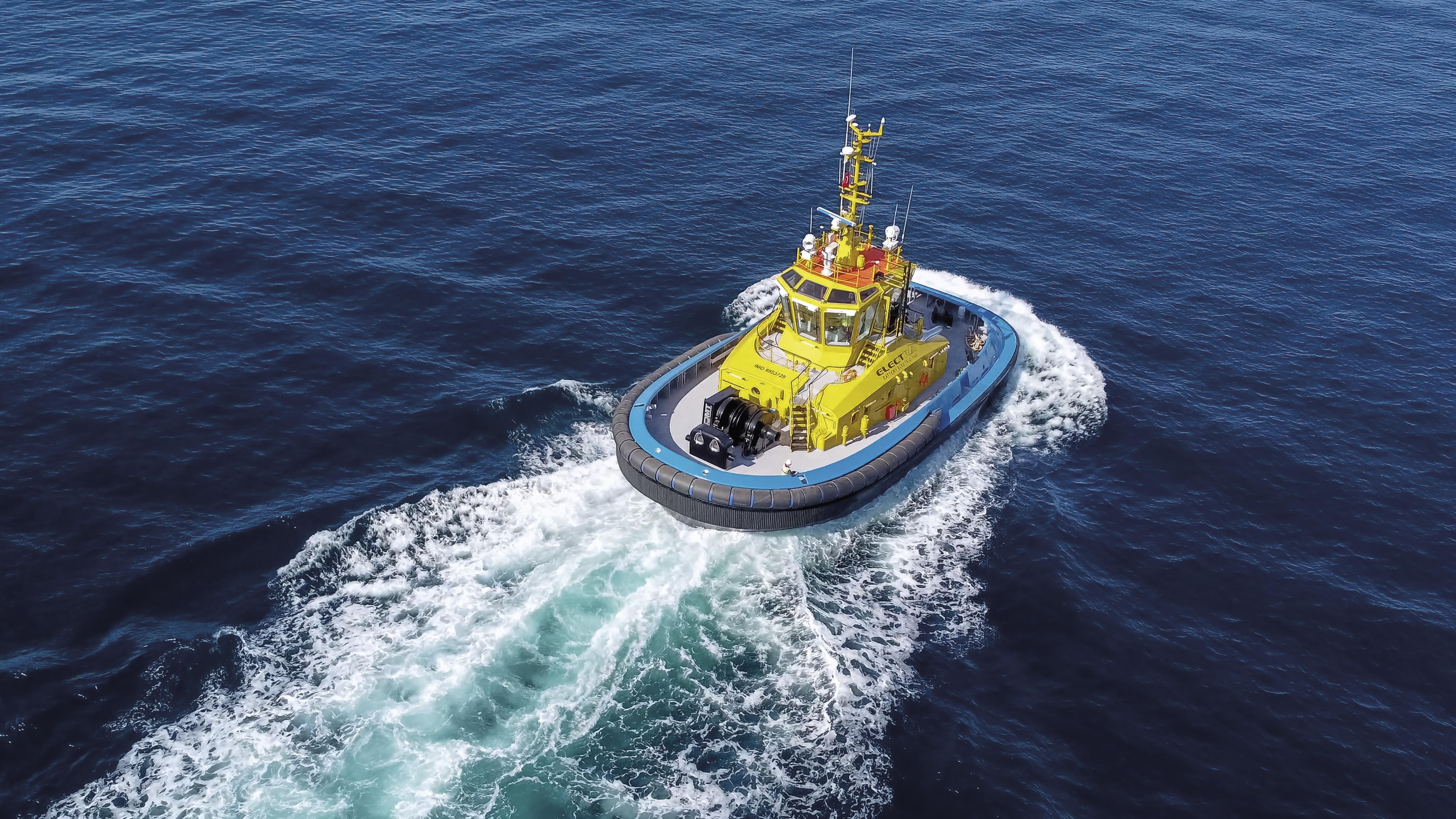
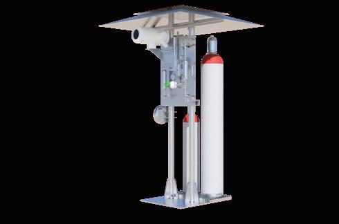
With over 60 years of experience, we seek creative solutions for a more sustainable business and our mission is to serve our clients with safety and operational excellence. We have the ability to provide innovation and solutions to our clients by understanding their specific challenges on the path to decarbonization, establishing strategic alliances with the best designers and tugboat builders, and allocating the necessary resources for the implementation of their sustainable projects.

Managing Editor
James Little james.little@palladianpublications.com
Senior Editor
Elizabeth Corner
elizabeth.corner@palladianpublications.com
Editor Jessica Casey jessica.casey@palladianpublications.com
Assistant Editor
Oliver Kleinschmidt oliver.kleinschmidt@palladianpublication.com
Sales Director Rod Hardy rod.hardy@palladianpublications.com
Sales Manager Will Powell will.powell@palladianpublications.com
Production Designer Amy Babington amy.babington@palladianpublications.com
Head of Events
Louise Cameron louise.cameron@palladianpublications.com
Event Coordinator
Chloe Lelliott chloe.lelliott@palladianpublications.com
Digital Events Coordinator
Merili Jurivete merili.jurivete@palladianpublications.com
Digital Content Assistant
Kristian Ilasko kristian.ilasko@palladianpublications.com
Junior Video Assistant
Amélie Meury-Cashman amelie.meury-cashman@palladianpublications.com
Digital Administrator
Nicole Harman-Smith nicole.harman-smith@palladianpublications.com
Administration Manager Laura White laura.white@palladianpublications.com
Happy New Year!
As we welcome 2025, the 82nd Golden Globe Awards kicked off awards season in Beverly Hills, California, where Emilia Pérez won the most awards for motion picture and television series (four), with The Brutalist coming in second (three).1
After its success last year, eyes will be on the US to see if America can retain its crown as the world largest LNG exporter. However it plays out, the US will remain in the spotlight, with Trump’s inauguration only bringing potential for further momentum.
President Trump’s election will likely help this endeavour, having pledged to lift the Biden Administration’s pause on approvals for new LNG projects on his first day in office. However, as Wood Mackenzie has stated in its new report, it believes new final investment decisions for new US LNG projects might happen more slowly than the administration might want.2 In addition, as Reuters has reported, Advisers to Trump are urging him to be patient regarding restarting approvals for LNG export licenses so as to avoid any decisions being overturned in court.3
Nevertheless, with many projects starting production, construction, or having already signed guaranteed contracts (such as Venture Global’s CP2 LNG project, Cheniere Energy’s Corpus Christi facility, and Mexico Pacific’s Saguaro LNG),4 the US remains in a strong position, and Glenfarne Energy Transition’s interview later in this issue highlights the US’ growing importance.
Another topic of discussion that may impact the LNG industry is EU methane regulation. Wood Mackenzie predicts that limited clarity will emerge on how these regulations will be framed. The first date in the diary for LNG importers is 5 May 2025, by which time importers will need to provide information such as whether the producer/exporter of the gas is monitoring methane emissions, carrying out leak detection surveys, and the gas emission’s methane intensity.2 This could either trigger the potential for low-carbon LNG that could transform LNG trade, or cause more complications –it all depends on the clarity and execution of the regulations.
Kalkine Group has also forecasted the decarbonisation of LNG production as a key trend for 2025. In their keynote report at the beginning of this issue, Kalkine examines various strategies such as carbon capture and storage, the integration of renewable energy, and methane emissions reductions as ways for major LNG-producing nations to achieve this. As discussed in various articles throughout the issue, valves, coatings, and boil-off gas management are all things companies can consider to reduce the environmental impact of their operations.
Whatever 2025 may hold, LNG Industry will again be here to bring you the latest on any updates, developments, new projects or regulations, with each issue helping to keep you up-to-date and well informed. We look forward to seeing how it plays out.
1. ‘The 82nd Golden Globe Awards – Winners’, Golden Globes, (6 January 2025), https://goldenglobes. com/articles/the-82nd-golden-globe-awards-winners/
2. ‘Global Gas and LNG: 5 things to look for in 2025’, Wood Mackenzie, (January 2025), www.woodmac.com/news/opinion/gas-lng-2025-outlook
3. GARDNER, T. and RENSHAW, J., ‘Trump promised swift action on LNG exports, but advisers preaching patience’, Reuters, (7 January), www.reuters.com/business/energy/trump-promised-swiftaction-lng-exports-advisers-preaching-patience-2025-01-07
4. WILLIAMS-DERRY, C., ‘IEEFA comments to DOE on LNG export terminals and permitting’, Institute for Energy Economics and Financial Analysis, (8 January 2025), https://ieefa.org/ resources/ieefa-comments-doe-lng-export-terminals-and-permitting


bp has begun flowing gas from wells at the Greater Tortue Ahmeyim (GTA) Phase 1 LNG project to its FPSO vessel for the next stage of commissioning.
GTA, offshore Mauritania and Senegal, is one of the deepest offshore developments in Africa, with gas resources in water depths of up to 2850 m. Once fully commissioned, GTA Phase 1 is expected to produce around 2.3 million tpy of LNG.
Gas from GTA Phase 1 is being introduced to the GTA FPSO approximately 40 km offshore, where water, condensate, and impurities are removed. From there, it will be transferred via pipeline to a floating LNG vessel located 10 km offshore, where it will be cryogenically cooled, liquefied, and stored before being transferred to LNG carriers for export. Some of the gas will be allocated to help meet growing energy demand in the two host countries.
GTA construction activities have generated more than 3000 local jobs, and the project has engaged with around 300 local companies across Mauritania and Senegal. bp and partners have invested in local workforce development and started a multi-million-dollar social investment programme that aims to enhance local quality of life and create long-term opportunities for local development.
ADNOC Gas plc and its subsidiaries, a world-class integrated gas processing company, has announced the awarding of three enabling contracts worth US$2.1 billion for an LNG pre-conditioning plant (LPP), compression facilities, and transmission pipelines to supply feedstock to the Ruwais LNG project.
The LPP and compression facilities will be located within ADNOC Gas’ Habshan 5 plant, part of one of the world’s largest integrated gas processing complexes. The five plants of the Habshan Complex have a combined capacity to process 6.1 billion ft3/d of gas. The newly awarded transmission pipelines will connect the Habshan Complex with the Ruwais LNG facility.
The largest contract, valued at US$1.24 billion for the LPP, was awarded to a consortium consisting of Engineering for the Petroleum and Process Industries (ENPPI) and Petrojet. A US$514 million contract for transmission pipelines was awarded to the China Petroleum Pipeline Engineering Company, while Petrofac Emirates LLC will develop the new compression facilities under a US$335 million contract.
The three contracts will establish the key infrastructure needed to supply feedstock to the Ruwais LNG export facility. This investment is part of the US$15 billion CAPEX plan through 2029, as outlined in ADNOC Gas’ recent strategy update.
D TEK, Ukraine’s largest private energy company, has taken delivery of its first cargo of LNG from the US, after the LNG shipment docked in Greece.
The consignment of approximately 100 million m3 of gas, or 1 TWh of energy, onboard the Gaslog Savannah arrived at the Revithoussa LNG terminal on the morning of 27 December 2024.
D.TRADING, DTEK’s pan-European trading subsidiary, has purchased the entire cargo. Working with Greek and other partners, the LNG will now be regasified and exchanged through EU and Ukrainian gas networks.
The shipment is part of broader efforts to enhance Ukraine and Europe’s energy security by reducing reliance on Russian
supplied gas. Its arrival comes just days before Ukraine ends an arrangement transporting Russian gas to the EU via its territory.
D.TRADING expects the consignment to be the first of a number of such shipments from the US, and is looking to expand its LNG activities into northern Europe and the Baltics.
D.TRADING is bringing in this first cargo via Greece due to restrictions on LNG transits into the Black Sea and Ukraine directly. Instead, it will use regasification terminals like Revithoussa together with cross-border pipelines such as the Vertical Corridor initiative, which transmits gas between Greece, Bulgaria, Romania, Hungary, Slovakia, Moldova, and Ukraine.
Chart Industries, Inc., a global leader in clean energy and industrial gas solutions, has signed a global master goods and services agreement (enabling agreement) with ExxonMobil.
This enabling agreement sets the terms, conditions, and commercial framework for Chart to provide LNG equipment, technology, and services for ExxonMobil’s global portfolio of projects. Specifically, the agreement includes the supply of cold boxes, as well as Chart’s proprietary IPSMR® process technology.
Under the agreement, ExxonMobil and Chart will deploy a design once, and then build many concepts to optimise cost, schedule, and quality for LNG projects globally.
CB&I has been awarded a substantial lump sum contract by TJN Ruwais JV for EPC of two cryogenic tanks and associated civil, structural, mechanical, and piping works for its Ruwais LNG project, Abu Dhabi, UAE. Once complete, the Ruwais LNG project will be the first net-zero LNG facility in the Middle East. TJN Ruwais JV is a joint venture between Technip Energies France-Abu Dhabi, JGC Corp., and NMDC Energy.
Under the contract, CB&I will deliver two 180 000 m3 full containment concrete LNG tanks, including all piping and civil infrastructure. Project delivery will be led from CB&I’s UAE office for tank construction, the Plainfield office (Illinois) in the US for engineering, and CB&I’s Saudi Arabia and Thailand offices will provide fabrication and modularisation support, respectively.
CB&I’s construction activities are expected to commence in November 2025, with project completion targeted in early 2028.
Seaboard Marine has announced the arrival of the Seaboard Victory, the second vessel in its cutting-edge LNG-powered V-Class fleet. The Seaboard Victory recently made its inaugural calls at the ports of Callao and Pisco, Peru, enhancing Seaboard Marine’s ability to provide sustainable and efficient maritime transportation.
With a capacity of 3500 TEU, including over 1000 refrigerated container plugs, the Seaboard Victory brings added reliability and increased capacity to key trade routes across the Americas. This state-of-the-art vessel is powered by LNG, significantly reducing emissions while improving operational efficiency and aligning with Seaboard Marine’s ongoing commitment to environmental stewardship.
The Seaboard Victory has joined a strategic rotation of ports in the Caribbean Basin, Central America, and South America. Its advanced features and increased capacity are already positively impacting trade routes, especially for perishable and high-demand cargo.
The Seaboard Victory is one of eight LNG-powered vessels set to be integrated into Seaboard Marine’s fleet by the end of 2025.
X Excelerate Energy completes 3000th LNG ship-to-sip transfer operation
X Venture Global ships first cargo from Plaquemines LNG
X Cheniere achieves first LNG at the Corpus Christi Stage 3 project X Samsung Heavy Industries picks TMC Compressors for 15 LNG carriers


Our LNG projects under construction and development are designed to meet rising global energy demand, improve energy security for American allies and advance environmental stewardship – all while creating new jobs and supporting the local community.
10 – 11 February 2025
6th American LNG Forum
Texas, USA
https://americanlngforum.com
10 – 12 March 2025
The 11th International LNG Congress (LNGCON) 2025
Amsterdam, the Netherlands
https://lngcongress.com
11 – 12 March 2025
StocExpo 2025
Rotterdam, the Netherlands www.stocexpo.com
07 – 08 April 2025
7th Global LNG Forum
Barcelona, Spain
https://lng-global.com
19 – 23 May 2025
29th World Gas Conference (WGC2025)
Beijing, China
www.wgc2025.com
10 – 11 June 2025
Gas, LNG & The Future of Energy 2025
London, UK
www.woodmac.com/events/ gas-lng-future-energy
09 – 12 September 2025
Gastech Exhibition & Conference
Milan, Italy
www.gastechevent.com
Baker Hughes, an energy technology company, has announced an order from Bechtel Energy Inc. to supply gas technology equipment for two liquefaction plants with a total capacity of approximately 11 million tpy for Phase 1 of Woodside Energy Group Ltd’s Louisiana LNG development opportunity. The order marks a significant milestone as Woodside targets final investment decision (FID) readiness from 1Q25.
The award, which includes eight main refrigeration compressors driven by LM6000PF+ gas turbines and eight expander-compressors, leverages Baker Hughes’ LNG technologies to support Bechtel and Woodside. Baker Hughes’ history of working with Bechtel and Woodside will support the delivery of Phase 1 of the project.
The European Commission has approved, under EU State aid rules, an estimated €4.06 billion German measure to support the operation of four FSRUs for the import of LNG by Deutsche Energy Terminal (DET). The measure contributes to the achievement of the objectives of the REPowerEU Plan, by enabling the diversification of energy supplies and ensuring security of gas supply.
In December 2022, Germany had chartered four FSRUs and created the state-owned company DET, tasked with operating the terminals. The FSRUs are located in Brunsbüttel, Wilhelmshaven (two locations), and Stade.
The measure aims to address energy market disruptions caused by Russia's invasion of Ukraine and the halt of pipeline gas supplies from Russia to Germany. The FSRUs, two of which started operating quickly, provide an additional import route to replace part of the lost Russian gas and are a temporary solution until permanent onshore LNG terminals are completed in Germany to ensure long-term gas supply.
The aid, in form of a direct grant, covers the losses incurred by DET for operating the FSRUs until the end of their charter period. As they were chartered at the peak of the energy crisis when demand and costs were very high and their limited operating time frame does not allow for full cost recovery, these terminals were expected to operate at a loss from the outset. The total net contribution between 2023 – 2033 is expected to amount to €4.06 billion. In case of higher losses than expected, the total net contribution could amount to €4.96 billion.
Germany has committed to stop operating the Brunsbüttel and Stade terminals once the planned onshore LNG terminal at those locations become operational, preventing market overlap. Once the onshore LNG terminals are active, the FSRUs will be sub-let at market rates, following worldwide calls for interest open to all bidders and locations, until the lease contracts expire.
Going forward, the capacity of the terminals will be auctioned in three different products: (i) a minimum technical capacity, subject to a delivery obligation, needed to ensure that the terminals remain operational in steady regime, therefore available at all times to ensure gas security of supply; (ii) medium term (3 – 4 years); and (iii) short term (one year). Germany has also introduced safeguards to address possible undue distortions to competition.
The Commission assessed the scheme under EU State aid rules, in particular Article 107 (3)(b) of the Treaty on the Functioning of the EU (TFEU), which enables Member States to remedy a serious disturbance in the economy.

Chart’s LNG power generation solutions provide natural gas to hundreds of thousands of homes. This is one way Chart facilitates LNG as a safe, clean-burning fuel for energy, transportation and industry.

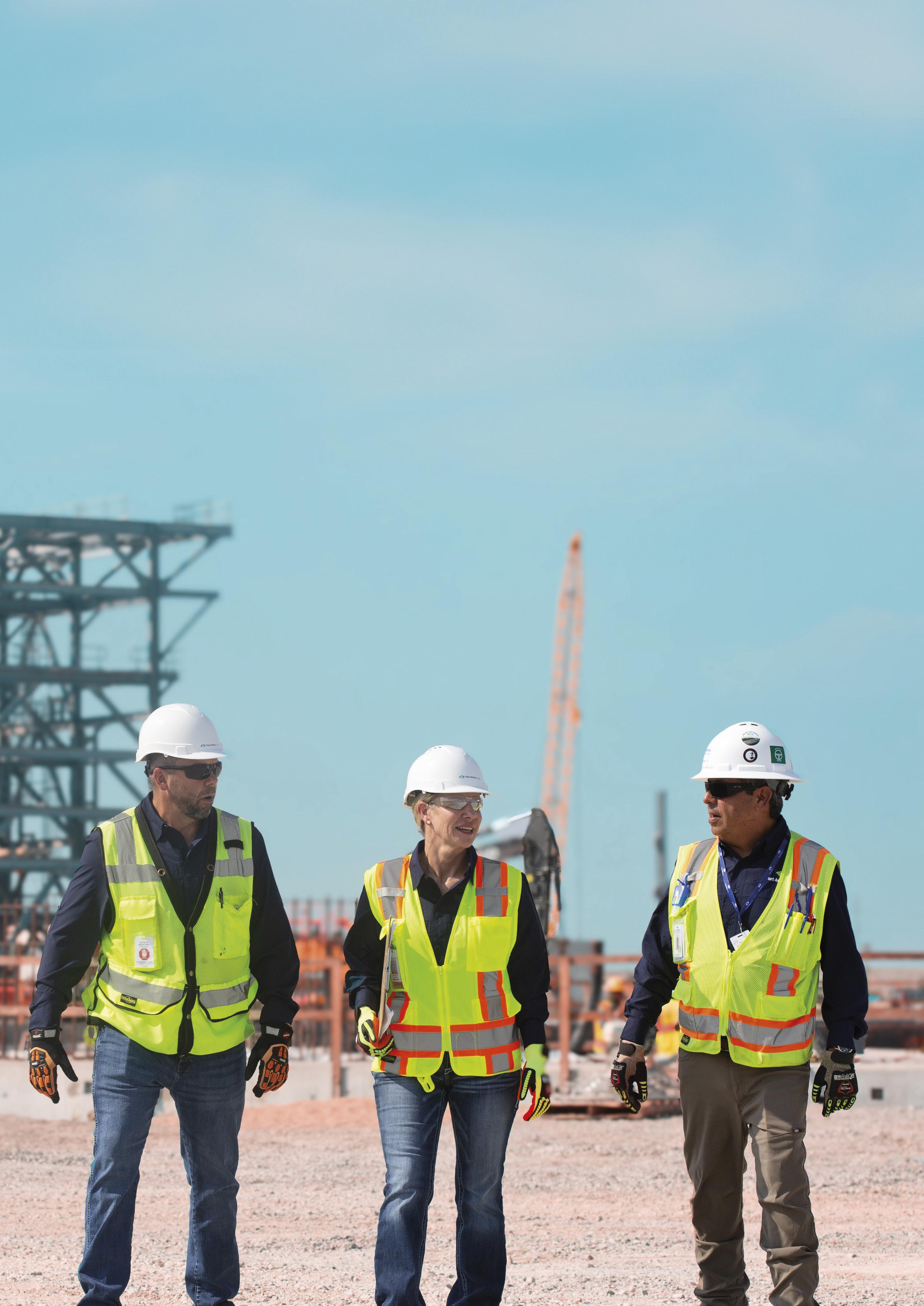
Kunal Sawhney, Kalkine Group, Australia, examines various strategies for decarbonising LNG production, including carbon capture and storage, renewable energy integration, and methane emissions reduction, across major LNG-producing nations.
s global energy consumption surged in 2023, so did greenhouse gas (GHG) emissions, reaching unprecedented levels. LNG, a relatively lower-carbon fossil fuel, has emerged as a critical transition energy source. However, significant emissions from the LNG supply chain necessitate urgent decarbonisation efforts to align with global climate targets.
Countries like Australia, Qatar, and the US are leading in technological innovations and regulatory policies aimed at reducing LNG emissions. While decarbonisation presents challenges such as high energy demands,

regulatory uncertainty, and added operational costs, advancements in low-emission technologies and carbon-neutral LNG are reshaping the industry. Decarbonising LNG is essential to maintaining its role as a viable transition fuel in the global shift toward a sustainable energy future.
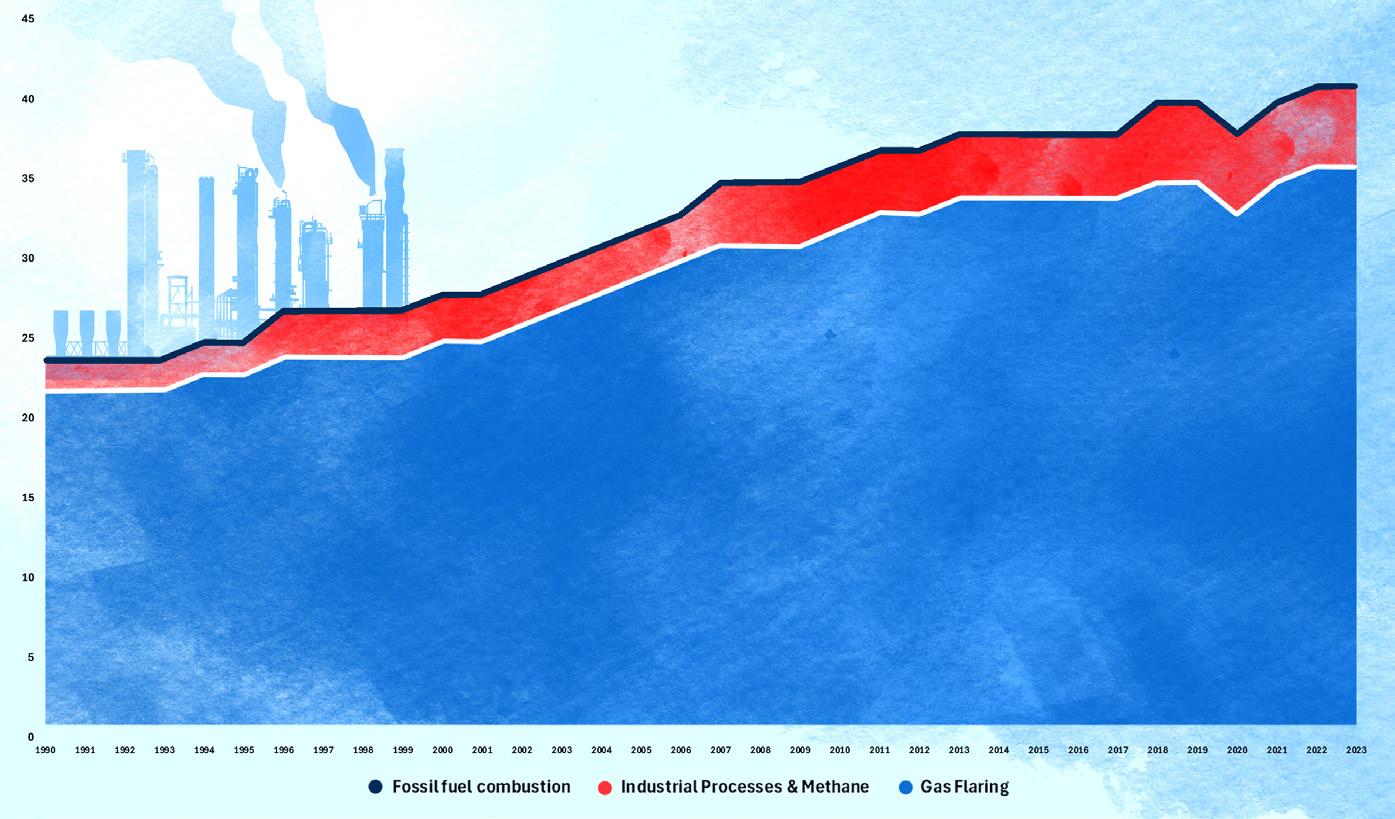
In 2023, global primary energy consumption reached a record high for the second consecutive year, growing by 2% to a total of 620 EJ. While fossil fuel consumption hit an
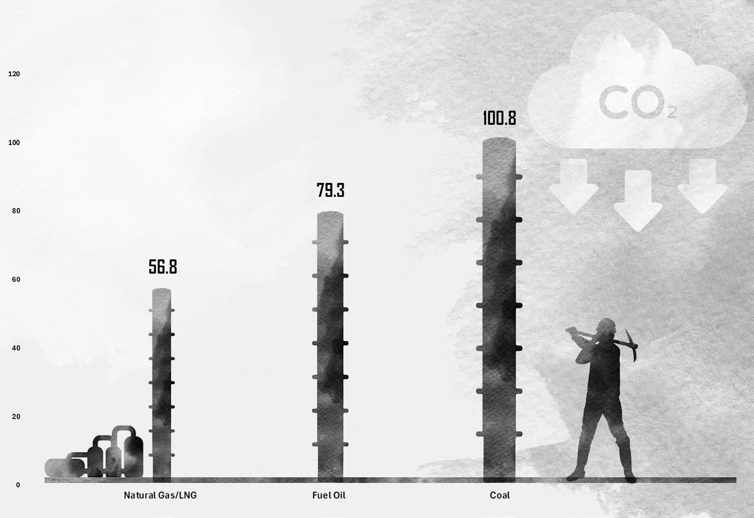
absolute record, its share in the energy mix declined slightly from nearly 81.9% in 2022 to 81.5% in 2023. Demand for natural gas, a relatively low-carbon fuel, remained stable. However, increased reliance on more carbon-intensive sources like oil and coal pushed energy-related GHG emissions to a new peak, exceeding 40 Gt of carbon dioxide equivalent (CO2-e) for the first time. Notably, CO2 emissions from fossil fuel combustion accounted for about 87% of total energy-related GHG emissions, remaining the largest contributor.
With energy-related GHG emissions reaching a new high, one of the pressing issues of the global energy industry is its decarbonisation. However, it is impossible to make such a transition overnight; therefore, a transitional fuel is needed – for example, natural gas as it has the lowest carbon emissions rate of all hydrocarbons fuels.
However, the global LNG market is undergoing a rapid evolution to meet the growing demand for cleaner energy,
particularly in emerging markets, while adapting to shifting geopolitical, regulatory, and environmental dynamics.
As LNG infrastructure expands and technology advances, the market diversifies, with an increasing number of players and innovations reshaping the industry. Challenges such as regulatory pressures, infrastructure limitations, and environmental concerns introduce uncertainty and complexity. In response, LNG operators are focusing on decarbonisation – an essential strategy to reduce emissions across the LNG value chain, from upstream production to downstream distribution.
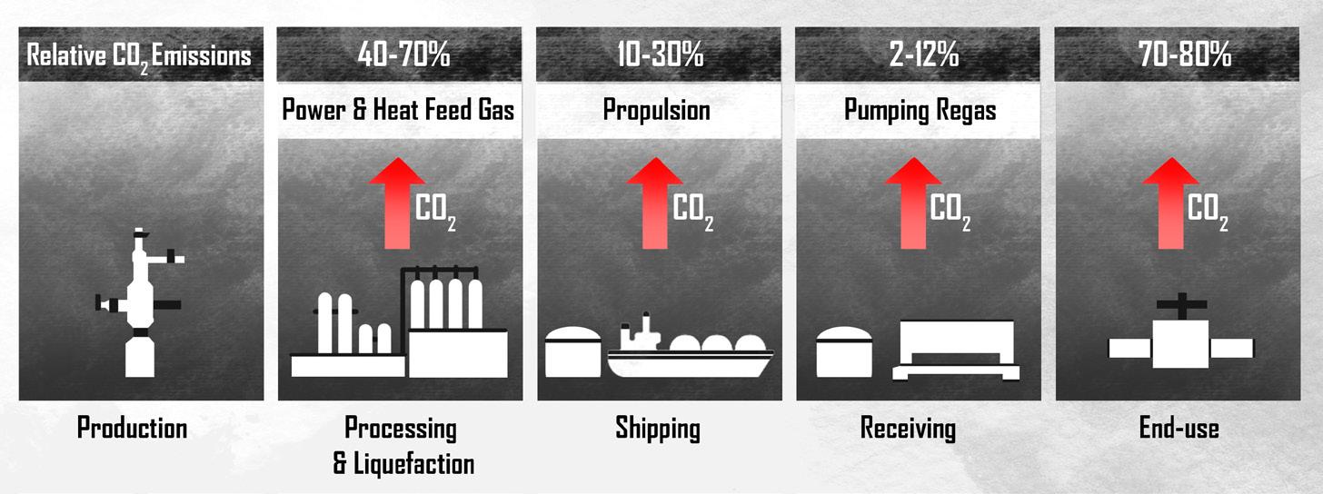
Decarbonisation of LNG production refers to reducing or eliminating the GHG emissions generated throughout the LNG value chain – from extraction and processing to liquefaction, transport, and regasification. As shown in Figure 3, 40 – 70% of total CO2 emission in the LNG value chain occurs in the processing and liquefaction stage.
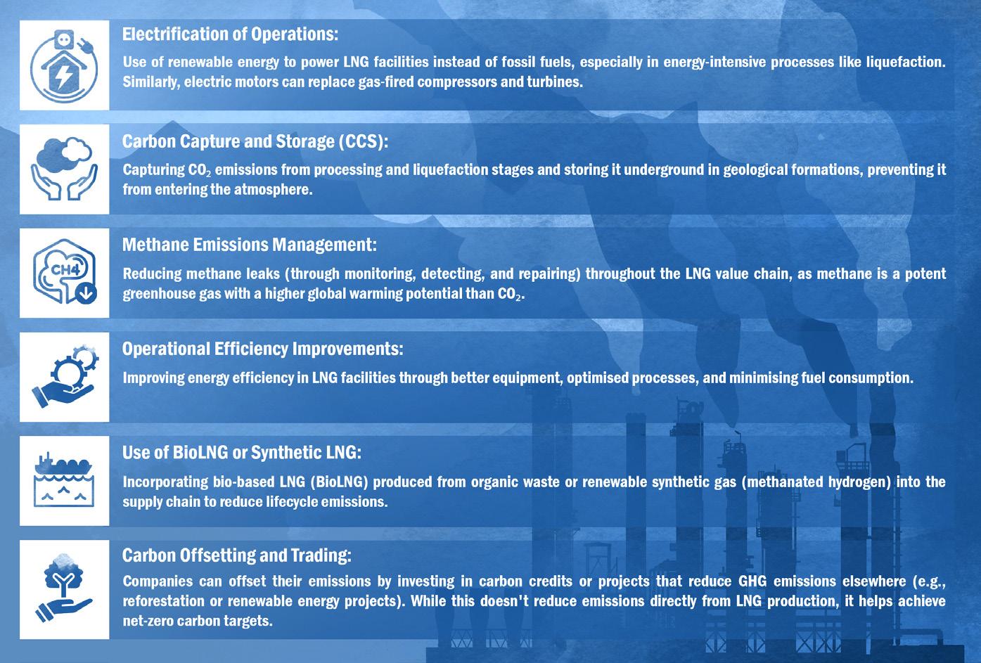
This process is part of the broader effort to make LNG production more sustainable and aligned with global climate targets by reducing its carbon footprint.
Steps taken by countries to decarbonise LNG production
Countries are adopting various policies, infrastructure investments, and technologies to decarbonise LNG production. Some notable approaches from major LNG producers include:
z Carbon capture and storage (CCS): Australia is advancing CCS projects, such as Chevron’s Gorgon LNG project, designed to store up to 4 million tpy of CO₂.
z Renewable energy integration: Some facilities are trialing solar power to meet part of their energy needs, aligning with national climate goals.
z Government support: Australia provides subsidies for low-emission technology, including CCS and hydrogen, under its Technology Investment Roadmap.
OUR LATEST COATINGS BREAK CONVENTION. YOURS.
It’s common to reuse coatings specs from previous projects – especially coatings that performed well. But our newest coatings may o er even greater durability, lower costs or additional advantages, like insulating without the need for an exterior system. So don’t pick up the same old specs until you know what our latest coatings technologies can do for you.
Scan to upgrade your specs for complete asset protection.

z Efficient technologies: Qatar is investing in high-efficiency equipment, such as in the North Field East project.
z Carbon offsetting: LNG producers are offering carbon-neutral cargoes via carbon credits and renewable energy.
z CCS expansion: Qatar aims to increase CCS as part of its National Vision 2030.
z Electrification: Producers like Venture Global LNG are incorporating renewable energy, such as solar, to power operations.
z Policy incentives: Tax credits under the 45Q provision encourage CCS investments.
z Methane emission regulations: The U.S. Environmental Protection Agency (EPA) has implemented stringent methane rules for oil and gas, including LNG.
z Carbon pricing: Canada’s carbon pricing mechanism incentivises emission reductions.
z Hydroelectric power: Projects like LNG Canada in British Columbia use hydroelectricity to cut emissions.
z CCS and methane reduction: Federal and provincial funding support cleaner LNG operations.
z Electric LNG facilities: Equinor’s Hammerfest LNG plant uses hydroelectric power, reducing fossil fuel reliance.
z Strict regulations: Norway enforces strict emission rules for LNG production.
z Carbon pricing: Norway’s carbon pricing and offset initiatives push companies toward carbon-neutral solutions.
z Carbon-neutral LNG imports: Japan is signing carbon-neutral LNG contracts, spurring exporters to reduce carbon footprints.
z Investments in CCS and hydrogen: Japan supports CCS and green hydrogen as part of its energy transition.
z Carbon border adjustment mechanism (CBAM): CBAM imposes costs on carbon-intensive imports, motivating exporters to cut emissions.
z Demand for carbon-neutral LNG: European buyers’ preference for low-carbon LNG drives suppliers toward cleaner production.
z Methane standards: The EU proposes strict methane standards for energy imports, encouraging global LNG producers to reduce leaks.
These steps reflect a combination of regulatory pressures, technological advancements, and market demand shaping LNG decarbonisation across the globe. While progress varies by country, these actions collectively help to drive lower-emission practices in LNG production and align the sector with global climate targets.
Decarbonisation is having a profound impact on the gas and LNG industry, reshaping its operations, economics, and role in the global energy landscape. There are some key ways in which decarbonisation is influencing this sector.
Increased capital in low-carbon technologies
To meet decarbonisation targets, companies are redirecting investments toward low-emission technologies. This shift in investment means more capital allocation toward research, development, and implementation of sustainable solutions.
There is a growing trend in ‘carbon-neutral’ or ‘green’ LNG contracts, especially from buyers in Europe and Asia, who are willing to pay a premium for LNG with offset or low-carbon options.
Decarbonisation is pushing gas and LNG operators to adopt new technologies adding
complexity to traditional operations, requiring significant modifications to existing facilities and supply chains.
Technologies such as CCS and electrification require additional CAPEX and OPEX, making LNG production more costly. Maintaining competitiveness may become challenging, especially for projects in regions with lower-cost fossil fuel operations.
Market demand shift and competitiveness
As renewable energy and green hydrogen gain traction, there is a risk that LNG may lose its status as a ‘transition fuel’ and face declining demand over time. Some buyers view LNG as a temporary solution, and this long-term demand uncertainty affects investment decisions and the overall strategic direction of the industry.
Customers are beginning to demand detailed carbon footprint information on LNG cargoes, prompting companies to improve emissions tracking and reporting. Complying with these requirements adds operational complexity and can create competitive pressure among producers.
Profitability concerns
The higher costs of decarbonisation initiatives, coupled with potential carbon taxes and the expense of purchasing carbon offsets, can reduce margins for LNG producers. Companies without the resources to invest in decarbonisation could struggle to compete, potentially leading to consolidation in the industry.
Decarbonisation efforts may enable producers in regions with access to renewables, CCS infrastructure, or carbon-neutral LNG contracts to gain a competitive edge. This could shift market leadership towards countries with strong decarbonisation policies and resources.
and social license to operate
Enhanced public and investor scrutiny
Decarbonisation aligns the LNG industry with climate action goals, which is increasingly important for securing investment and public support. Companies prioritising decarbonisation are better positioned to attract capital, satisfy stakeholders, and improve their reputations.
Environmental, social, and governance (ESG) standards are becoming critical for many investors. By decarbonising, LNG companies can appeal to ESG-conscious investors
and stakeholders, which is particularly important as global capital shifts toward sustainable investments.
Decarbonising LNG production presents several significant challenges, as the process is complex, energy-intensive, and often relies heavily on fossil fuels.
Energy-intensive processes
LNG production, especially the liquefaction stage, requires a vast amount of energy, which is typically supplied by natural gas itself. Switching to renewable sources is challenging due to the scale of power needed and the continuous operation requirements of LNG plants.
Limited renewable integration
In remote locations, renewable energy infrastructure may not be available or reliable enough to fully power LNG facilities, limiting opportunities for electrification.
Technical and economic feasibility
While CCS is a potential solution for capturing CO2 emissions from LNG production, the technology is still costly and not yet widely implemented at scale. Significant investment and infrastructure are required for capture, transportation, and storage of CO2.
Site-specific constraints
Not all LNG production sites have nearby suitable geological formations for CO2 storage. Transporting CO2 to distant storage sites can be cost-prohibitive and logistically complex.
Detection and prevention
Methane is a potent GHG, and its unintentional leaks (fugitive emissions) throughout the LNG value chain are challenging to monitor, detect, and repair. Effective methane management requires advanced monitoring technology, which can be costly and is not yet widespread in industry.
Industry-wide standards and best practices for methane emissions control are still developing, making consistent reductions challenging across different operators and regions.
Transitioning LNG facilities to lower-emission operations, such as integrating renewable energy or implementing CCS, requires substantial upfront capital. Many LNG projects operate on thin profit margins, making large investments in decarbonisation difficult.
Funding and incentives
Government incentives or carbon pricing mechanisms are often necessary to make these projects economically viable, but such mechanisms are inconsistent globally, with varying levels of support for LNG decarbonisation.
and policy uncertainty
Inconsistent policies
Regulations for emissions control and incentives for decarbonisation vary widely by country and region. LNG producers operating globally must navigate different environmental regulations, some of which may lack clear guidance or enforcement, slowing the adoption of decarbonisation measures.
Carbon pricing and compliance
Not all regions have carbon pricing in place, and where it exists, the rates may not be high enough to incentivise decarbonisation fully. Uncertainty in future carbon pricing also affects long-term planning for LNG producers.
Market pressures and demand uncertainty
Market demand for ‘green’ LNG
While some buyers prioritise low-carbon LNG, many consumers still prioritise cost over emissions profiles. As a result, there may be limited demand for decarbonised LNG, creating an uncertain return on investment for producers.
Long-term demand uncertainty
LNG is often viewed as a ‘transition fuel’, and there are questions about its long-term role in a net-zero future,
especially as renewable energy adoption increases. This uncertainty can make companies hesitant to invest heavily in decarbonisation.
Supply chain and operational challenges
Complex LNG value chain
Decarbonising the entire LNG supply chain is challenging because emissions come from multiple stages, including extraction, transportation, and liquefaction. Co-ordinating decarbonisation efforts across all stages and stakeholders in the supply chain requires substantial collaboration.
Decarbonisation technologies such as CCS or electrification can complicate LNG facility operations, potentially leading to increased downtime, maintenance requirements, and risk of operational disruptions.
Public perception and stakeholder pressure
Skepticism toward LNG as a ‘transition fuel’
Environmental groups and some governments question LNG’s role in a net-zero future, given the methane emissions associated with natural gas. LNG companies face pressure to reduce emissions significantly to justify their product as a viable transition fuel.
Increased reporting and transparency requirements
Investors and stakeholders are demanding more detailed emissions reporting and transparency, putting additional pressure on LNG producers to adopt verifiable decarbonisation measures.
Despite these challenges, LNG companies are exploring ways to reduce emissions, but overcoming the economic, technical, and logistical barriers requires co-ordinated efforts from industry players, governments, and technology providers. Addressing these challenges is crucial to aligning LNG production with global decarbonisation goals and maintaining its role as a cleaner alternative to coal and oil in the energy transition.
Pumps and valves are an important component in the LNG process. LNG Industry asked several companies to discuss key topics regarding these pieces of equipment.
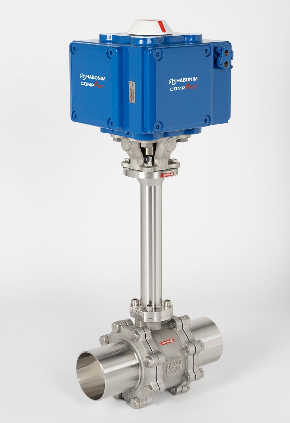
Tzur Layish is leading Habonim’s strategy and market focus in the LNG market, a rapidly growing market for Habonim in valves and valve automation, bringing innovation based on close co-operation with leading LNG system builders and equipment manufacturers around the globe. Tzur started his career at Habonim in 2018 and has 18 years of experience in industrial processes and instrumentation.
Johnny has been with Svanehøj for nearly 15 years, and since 2019 has been CSO with the overall responsibility for sales and projects. Over this period, Svanehøj has established itself as a specialist in LNG pump solutions, starting with deepwell (DW) cargo pumps in 2009, followed by DW fuel pumps in 2016, and most recently cryogenic submerged (CS) fuel pumps in 2022 and high-pressure piston (HPP) pumps in 2023.

Q1. Why are pumps and valves considered fundamental to the LNG process?
Tzur Layish, Habonim, An ITT Company
The LNG process involves piping systems connecting the equipment and devices along them. Valves are essential to any piping system and in many of the devices involved. They allow, block, or regulate the flow of LNG in the system, both in regular operation and in emergencies. As such, the reliability of valves is of high importance. As LNG is in extreme cryogenic temperatures and has risks of flammability and explosion, valve safety is critical.
Johnny Houmann, Svanehøj
From a maritime perspective, fuel pumps are considered critical equipment due to their essential role in delivering LNG from the storage tanks to the main engine. Fuel pumps are vital not only for the basic operation of an
LNG-fuelled vessel, but also for ensuring safety, efficiency, and compliance with environmental regulations. High-quality pumps specifically designed for cryogenic conditions are crucial for maintaining stability, optimising performance, and ensuring high reliability in vessel operations.
Q2. How can the right pumps and valves improve cost-efficiency, and overall efficiency of the LNG process?
Tzur Layish, Habonim, An ITT
Valve quality affects system efficiency by preventing leaks, energy loss, and downtime. Moreover, as the valve flow-rate capacity is one of the bottlenecks in piping systems, selecting valve technology with higher flow-rate capacity, like ball valves, can allow designers to maintain the overall system flow rate while using smaller pipes. Such designs can cut the overall piping system costs by half.
Using a floating ball valve technology with bi-directional sealing capability for the LNG system allows even greater savings in CAPEX and OPEX, as this quarter-turn valve technology is the most cost-effective.
Based on ball valve technology, LNG flow control is significantly more cost-effective than alternative cryogenic valve technologies.
Johnny Houmann, Svanehøj
Keeping LNG in its liquid form requires cryogenic conditions of at least -162˚C. LNG pumps must therefore be highly reliable, durable, and constructed from materials that function optimally under cryogenic conditions. The greater the efficiency of a fuel pump, the more energy is converted into mechanical power, resulting in energy savings and the prevention of gas loss caused by heat generation and boil-off gas (BOG). A main design criterion at Svanehøj has been to ensure optimised energy performance and extended service intervals for all pumps in our portfolio, thereby shifting the focus in the industry from initial investment cost to lifetime cost. A comprehensive lifetime study, including tests and thorough calculations of the mechanical components, has concluded that a Svanehøj DW pump only requires servicing every five years during regular docking. In fact, all maintenance until 10 years/50 000 hours does not require access to the tank.
Q3. What are some of the recent developments for pumps and valves in the LNG industry, if any?
Tzur Layish, Habonim, An ITT Company
The development of Cryogenic Bi-Directional Flushing Ball valve technology, which is a recent innovation in valve technologies, opens a new way to design LNG piping systems with significantly lower costs and simplicity.
Johnny Houmann, Svanehøj
The growing adoption of LNG as a ship fuel has driven an increase in demand for high-pressure engines in specific maritime applications, owing to their lower emissions, higher efficiency, and superior fuel economy. In response to the need for leak-free components supporting high-pressure LNG ship engines, Svanehøj has developed the HPP Triplex Pump Unit, a complete high-pressure pump unit designed exclusively for maritime purposes. With this design, the company has introduced an innovative low-pressure sealing arrangement for the cold end that reduces friction, ensuring longer service intervals. Additionally, Svanehøj has incorporated a new inlet valve design to ensure high efficiency and low-pressure drop.
Q4. As LNG becomes more popular and new gas sources are utilised, will this require changes in how pumps and valves are designed or used?
Johnny Houmann, Svanehøj
From a maritime perspective, it is crucial to ensure that cryogenic pumps can effectively handle impure LNG. Traditionally, fuel pumps have faced challenges with clogging, leading to reduced efficiency, operational disruptions, and excessive wear. Svanehøj has addressed this issue, designing both its DW fuel pumps and submerged fuel pumps for LNG to manage impurities in liquefied gas without compromising performance or reliability.
Q5. What component of a pumps and valves is most prone to failure and thus requires the most maintenance?
Layish, Habonim, An ITT Company
Valve sealing elements are prone to get worn out with cycling and time as operating the valve most affects the valve’s steam-sealing arrangement. Unique steam-sealing technologies for LNG provide emission-free operations, fire-safe capabilities, and durability that allows no sealing maintenance for long periods or cycling.
Johnny Houmann, Svanehøj
Traditional filters in submerged cryogenic pumps are prone to clogging due to impurities in the LNG. This leads to pump downtime and excessive wear on bearings and motor components. In response, Svanehøj’s new series of submerged LNG fuel pumps, launched in 2023, features a redesigned filtering system. The primary gas flow circulates around the


LNG filter at very high speed, effectively dislodging particles and preventing clogging.
Q6. Numerous types of pumps and valves exist. Describe the technology behind one of your most popular pumps and valve products.
Tzur Layish, Habonim, An ITT Company
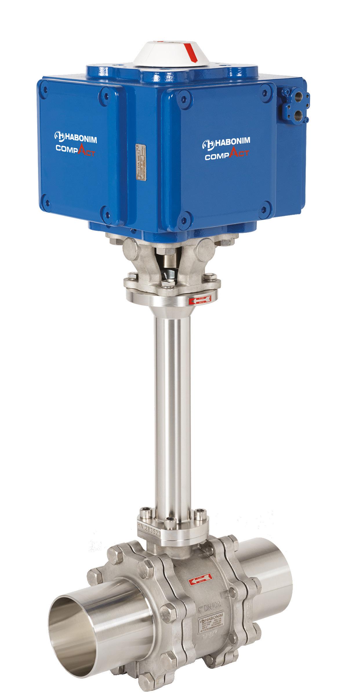
Habonim’s patented Bi-Directional Floating Ball valve technology is based on releasing any potential ‘in cavity’ overpressures without the traditional use of a ‘pressure relief hole’ in the valve ball, which, in turn, turns the valve into a unidirectional valve.
This bi-directional sealing capability allows the use of quarter-turn floating ball valves to replace alternative valve technologies and achieve higher performances with lower costs.
Johnny Houmann, Svanehøj
The Svanehøj DW fuel pump is a long-shaft, multistage centrifugal pump that has achieved remarkable success, with over 1000 units sold since its introduction in 2016.
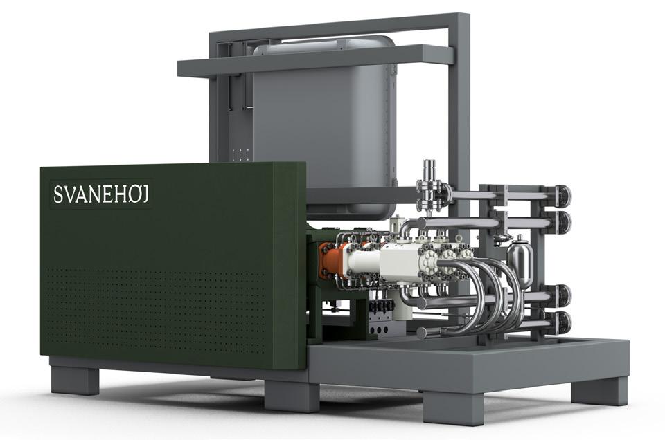
Svanehøj. Svanehøj has been developing pumps for LNG since 2009. A main design criterion has been to ensure optimised energy performance and extended service intervals for all pumps in the portfolio, thereby shifting the focus in the industry from initial investment cost to lifetime cost.
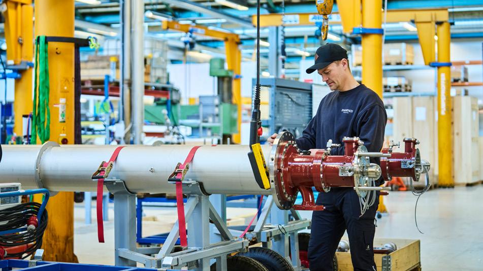
Svanehøj. In response to the need for leak-free components supporting high-pressure LNG ship engines, Svanehøj has developed the ‘HPP Triplex Pump Unit’, a complete high-pressure pump unit designed exclusively for maritime purposes.
All sensitive components (the electric motor, seals, and bearing systems) are positioned outside the tank. This design not only ensures easy access during service, but also prevents motor heat from contributing to increase in BOG and pressure inside the tank. The pump is equipped with a unique hermetically sealed MagDrive coupling, which eliminates the risk of gas leaking, enhancing safety and reliability in LNG applications.
Svanehøj DW pumps are designed for 5 years/25 000 hours service intervals and 10 years/50 000 hours between overhauls. Two patented design features – a static seal and a foot valve system – significantly enhance the ease of pump maintenance. When the static seal is activated, the inner magnet coupling, the main pump bearing, and the oil filter can be accessed, dismantled, serviced, or replaced without having to extract the pump from the tank. When installed in a caisson pipe, the unique foot valve system enables the pump to be fully extracted and serviced regardless of the tank’s contents or the liquid level. For many of the company’s customers, the foot valve system is a decisive factor, as it allows for immediate pump servicing without the need to empty the tank, significantly reducing downtime and operational disruption.
Q7. Outline a short case study on the use of pumps and valves at an LNG operation.
A common use of ball valve technology in LNG trailers and ISO tanks is the fire-block valve (FBV). This safety device shuts off LNG flow in case of fire. FBV is usually required in LNG transportation equipment and systems and is installed on the main LNG supply line.
LNG transportation systems usually require a high level of safety certification for inland transportation, like TPED or marine type approval for shipping.
Svanehøj’s DW pumps are equipped with a patented foot valve system that enables complete servicing of the pump –regardless of the tank’s contents or liquid level.
This feature proved invaluable when Svanehøj was called to an offshore installation vessel in Germany after the crew discovered a leak in a fuel pump during bunkering. By activating the foot valve system, Svanehøj’s service engineer identified the issue and began repairs within just three hours. Without the foot valve system, the fuel tank would have needed to be emptied and rendered gas-free before the pump could be extracted – a process that could have taken several days instead of hours and incurred substantial financial costs.
The foot valve system operates by utilising the tank’s internal pressure to keep the valve closed, as the surrounding pressure in the tank exceeds that in the pump caisson. The system is activated from outside the fuel tank. In the event of a leak or pump malfunction, the service engineer injects nitrogen to displace LNG from the pump caisson via the foot valve. Once the valve is securely closed and any remaining gas vented, the fuel pump can be safely extracted for a full overhaul or minor maintenance.
At Svanehoj, we are dedicated to developing the best and most comprehensive range of future fuel pump solutions to meet the need for carbon-neutral fuels, whether we talk LNG, LPG, ammonia, or methanol.
Our leading technology is developed based on our extensive background and knowledge from the maritime industry, and our proven and reliable pump technology is already part of more than 1000 Svanehoj Fuel Pumps operating in vessels around the world to advance the green transition.

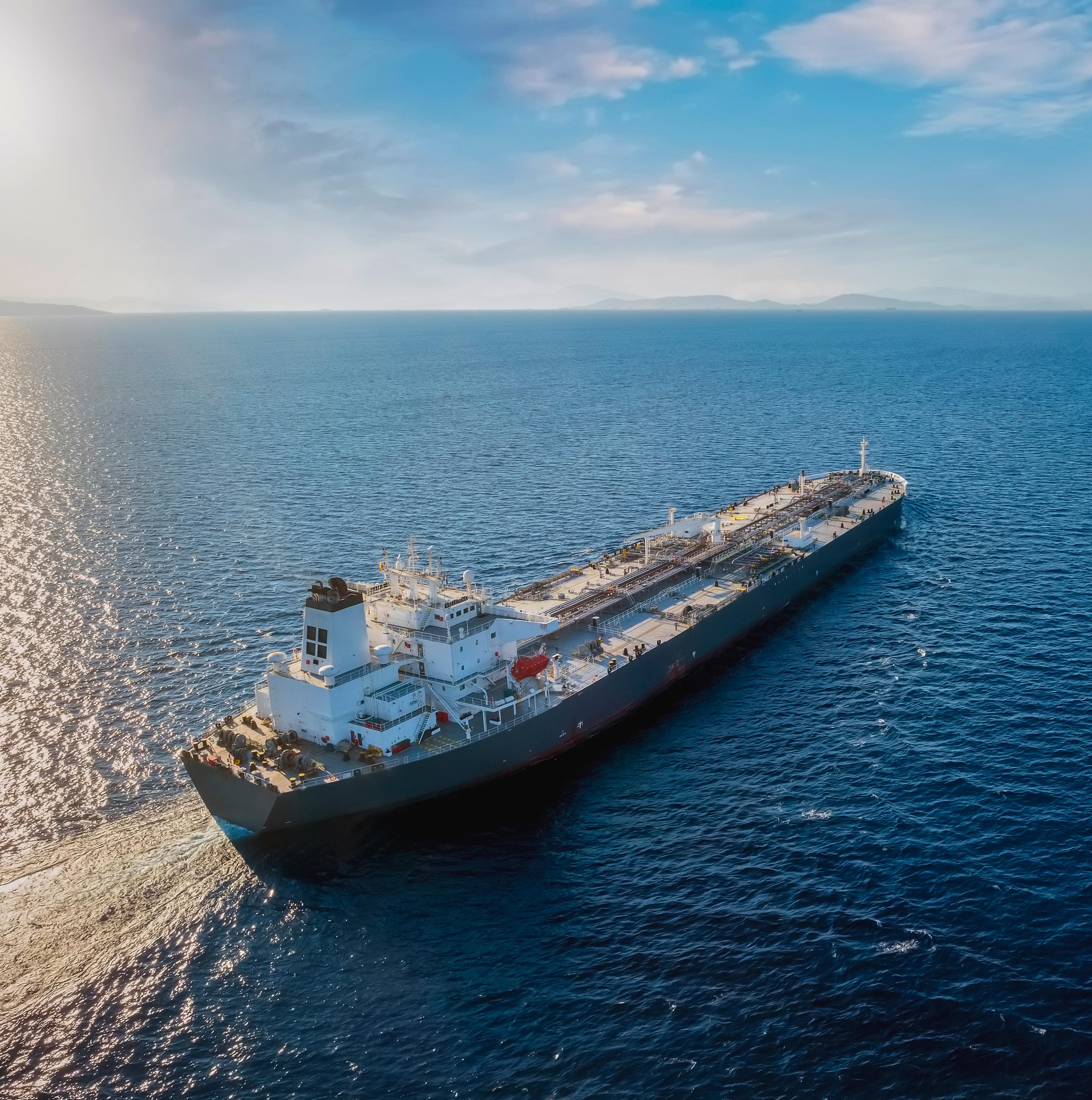
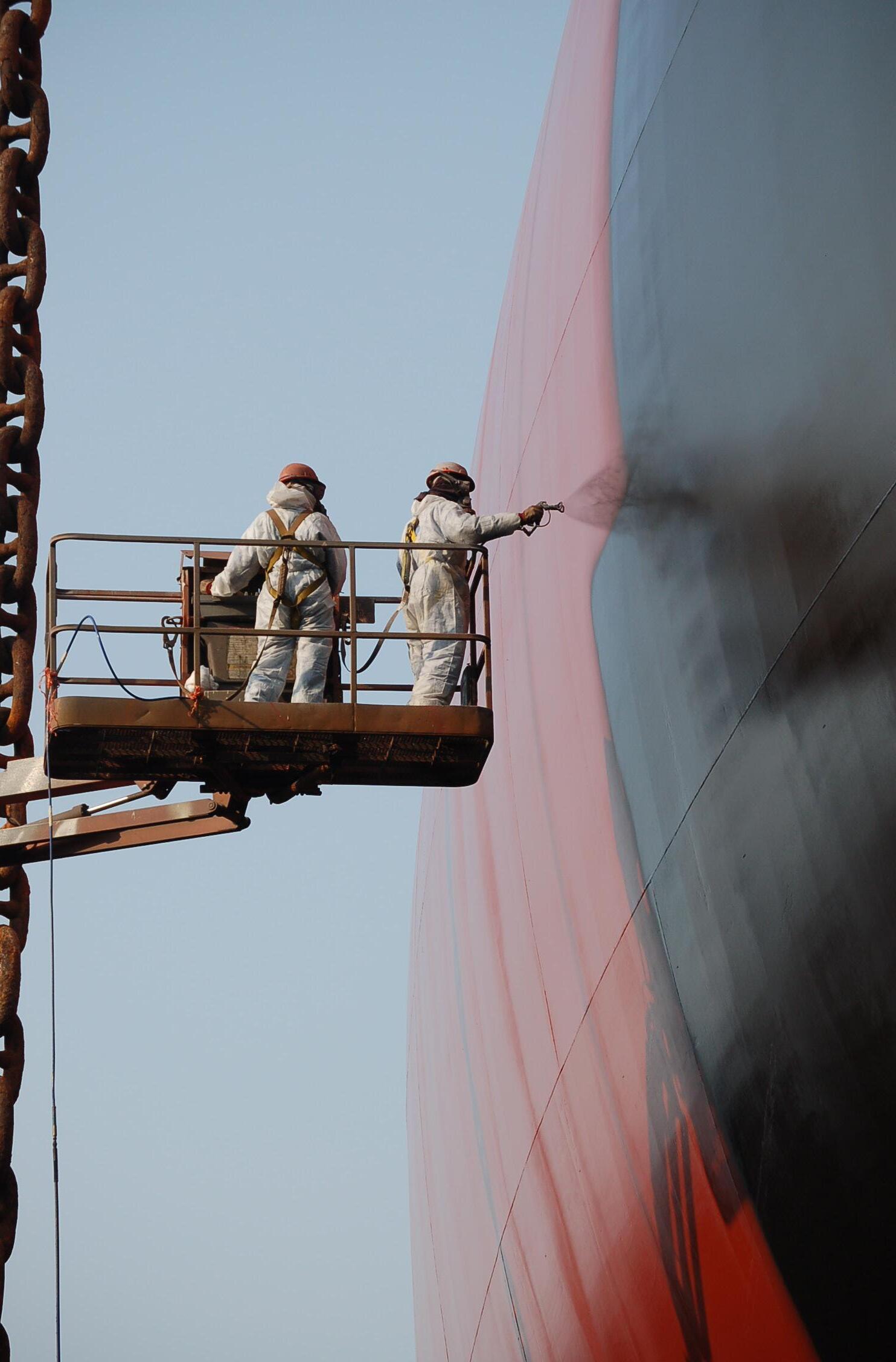
Justin Hair, Key Account Manager, Sherwin-Williams Protective & Marine, addresses how to shore up specifications to combat corrosion under insulation, safeguard storage tanks, and protect pipelines.
atural gas takes a complicated journey from inland extraction sites to LNG plants and coastal exporting terminals. Along the way, the infrastructure that moves and stores the material in either a gaseous or liquid state faces numerous corrosive threats that can create maintenance headaches for owners at best, or lead to dangerous leaks and catastrophic events at worst.
Such threats exist from upstream fracking sites to midstream pipelines and storage facilities to downstream processing facilities and distribution terminals. At every stage, owners must determine the best ways to stave off corrosion for as long as possible on pipelines, compressors, process vessels, storage tanks, and numerous other infrastructure assets. The longer those assets can perform, the better for the owner’s bottom line.
Specifying high-performance coatings is the optimal solution for buying extra time on the corrosion clock. Better performing coatings lead to longer asset service lives, plus longer-term cost savings

due to fewer planned and emergency maintenance shutdowns needed over the life of an asset. However, determining which solutions offer the best results can be difficult. This article will review some considerations for choosing the most appropriate coatings for various assets associated with LNG production and transmission, as well as reinforce the importance of having informed coating specifications for those assets.
Steady LNG market growth has spurred the need for additional infrastructure – including pipelines, compressor stations, storage tanks, and peak shaving facilities – to enable
continued progress. This activity is keeping global EPC firms on their toes as they manage various logistics associated with LNG infrastructure. Because many such projects involve an array of international suppliers, a logistical nightmare could materialise if various plug-and-play assets are not compatible when connecting everything together –particularly if the coatings do not meet strict international standards, such as ISO 12944 and NORSOK M-501.
The success of installing those assets, and ensuring everything will function as planned, hinges on having solid
specifications in place. Such protocols hold each supplier to the same standards, enabling a process vessel that is fabricated and coated in North America to connect seamlessly to piping produced in Latin America, that connects to a storage tank made from steel produced and coated in Asia. Each coating system used on those assets must be compatible with the ones used on any connected assets. In addition, asset owners will want the colours to be uniform for aesthetic purposes. Clear specifications should ensure both outcomes, particularly when using a coating supplier that offers uniform products that are available at the same quality and performance standards anywhere in the world. Such universal coatings ensure compatibility, colour matching, and performance on projects spanning multiple regions.
A common practice for EPC firms and asset owners alike is to base new coating specifications on previous ones that have worked well in the field over years of asset use. That certainly makes sense. However, there is a good reason to question even a specification with a sound performance history, as legacy specifications likely do not include newer materials now on the market. Those materials may offer better longevity, cost, maintenance, and performance, but they could be left out of consideration if no one speaks up.
Knowing this, it is important for EPCs and asset owners to connect with coating suppliers well ahead of finalising project specifications and before any infrastructure assets are created. Working together to understand the operating logistics and challenges of the project will help all parties consider every potential solution. With the longevity of assets being a primary goal, many newer coating formulations are likely to displace older specified materials.
Since older specifications are often used for new projects, it may be helpful to examine a particular category of coatings to demonstrate why considering newer solutions is advisable.
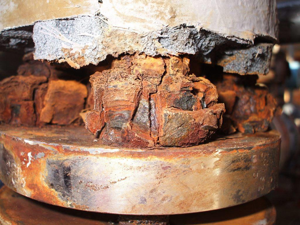
A good example are the coatings used to stave off the troublesome and potentially dangerous condition of corrosion under insulation (CUI) (Figure 1). This bane of many energy-related operations occurs underneath the insulation and cladding that is wrapped around storage tanks, piping, and other assets operating at hot or cold temperatures to insulate them. Moisture inevitably becomes trapped within those insulation systems and works its way down to the steel substrates underneath, accelerating corrosion potential.
Hidden from view, CUI can be very corrosive in nature due to moisture and condensation intrusion, varying pH ranges that occur based on the type of insulation materials used, and the intrusion of chlorides that is likely to occur due to the harsh coastal environments in which many LNG plants are located.
Consider stainless steel piping used to move process gas or fluid through an LNG facility. Covered in insulation, the piping is likely to encounter CUI at some point during its lifespan. In the coastal environments where LNG plants are typically located, that corrosion is likely to come in the form of chloride stress corrosion cracking (CSCC), which can cause cracking, pitting, and even leaks.
An EPC using an older specification could miss the fact that better CUI-mitigation coatings have entered the market and would therefore miss out on the improved outcomes a newer technology would deliver. Some enhanced options in that realm include newer spray-applied organic liquid coatings such as high-temperature epoxy phenolics, high-temperature, high-solids alkylated amide epoxies, and ultra-high-solids novolac amine epoxies.
Among the newer liquid CUI-mitigation coating options EPCs may not know are formulations featuring a high concentration – at least 25% – of micaceous iron oxide (MIO) pigment, which reinforces the coating for greater durability against impacts, chemicals, and corrosion (Figure 2). In addition, an ultra-high-solids advanced epoxy novolac with a functional chemical enhancement for CUI mitigation is available that performs even better than the MIO-enhanced formulations per heat cycling, CUI, UV erosion, DFT tolerance, and ISO testing.
EPCs may also not know they can eliminate CUI altogether by skipping the traditional insulation systems used on storage tanks, piping, and process vessels. Newer thermal insulative coatings that provide an advanced energy barrier to curb the transfer of heat rival the thermal retention capabilities of traditional insulation. They enable asset owners to forgo traditional insulation and cladding in favour of a few layers of coatings (Figure 3). Doing so literally eliminates the threat of corrosion forming underneath insulation because the insulation is no longer there.
Protecting the massive storage tanks that hold processed LNG for distribution is also critical. However, coatings play less of a role on certain tanks. For example, the double-walled carbon steel tanks that are insulated with concrete and referred to as full containment tanks typically remain uncoated (Figure 4), even when located in coastal regions. They may be coated for purely aesthetic reasons, using an acrylic-based coating due to its compatibility with concrete and its long-term gloss retention.
The story is different for storage tanks used for peak shaving facilities. Such tanks may be located in coastal regions where they require a robust protective coating system to combat the corrosive forces of the C5M environment. They may also be located inland where they face a less harsh C2 or C3 environment. In either case, EPCs would typically specify a zinc/epoxy/polyurethane or a zinc/epoxy/polysiloxane protective coating system for increased performance.
For tanks that will be coated, builders will typically prime steel plate in a shop before shipping it to the installation site for assembly. Primers should be specified with durability in mind, as plate loading and shipping damage, extended on-site storage, and on-site construction damage can all be issues. Using such primers can help dramatically with on-site construction schedules because if the shop primer fails during the construction process, complete removal is often required. That is a major problem that adds man hours – and costs – to the schedule.
At the fabrication shop, tank builders typically specify inorganic zinc coatings for shell plates due to their high zinc load and excellent corrosion protection. Their extended recoat windows also help. Once the tank has been constructed, coating applicators will address any damaged
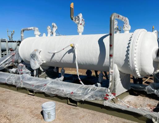
Figure 3. Using a thermal insulative coating system with an advanced energy barrier to curb the transfer of heat on process vessels and other assets can help LNG producers forgo the use of traditional cladded insulation systems while eliminating CUI altogether.
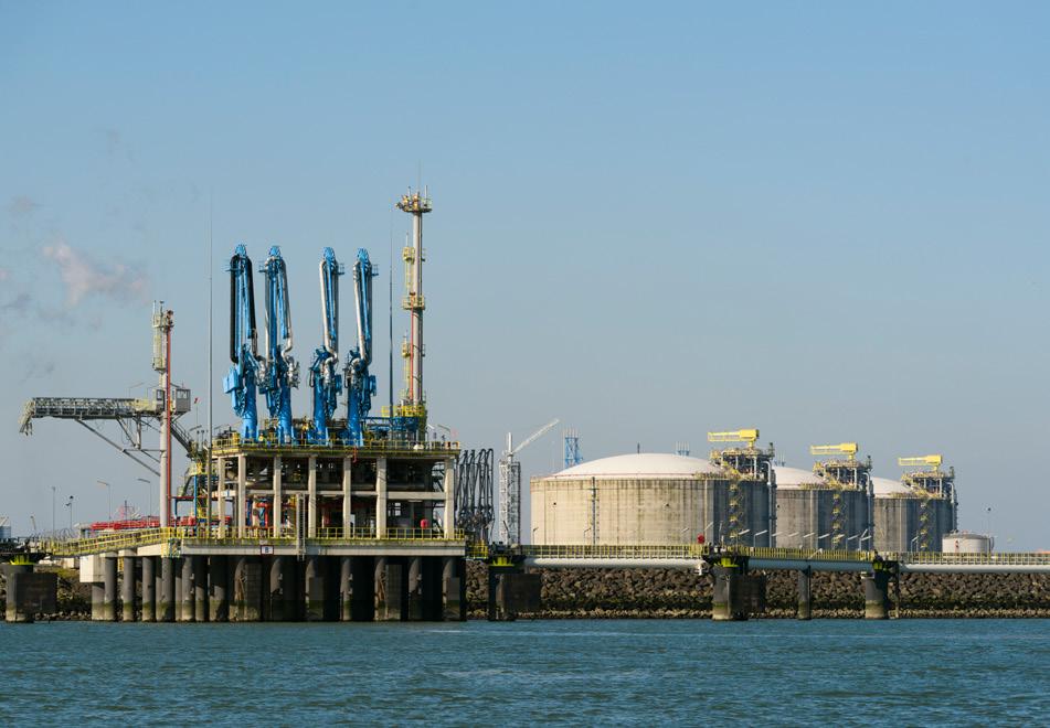
Figure 4. Most full containment tanks made from double-walled carbon steel and insulated with concrete remain uncoated unless the owner prefers a coating for aesthetic purposes. Source: Getty Images, Westend61.
areas and field welds first, coating them with an organic zinc or an epoxy primer/intermediate product before applying a finish coat.
That topcoat should offer high performance and may take the shape of a polyurethane material. Alternatively, a polysiloxane that meets the ISO 12944-6 Rev 4 standard for very harsh C5M environments may be used as a finish coat on these large scale assets. Polysiloxanes combine the properties of a high-performance epoxy and polyurethane to deliver effective long-term corrosion protection and weatherability. Robust zinc/epoxy/polyurethane systems have proven to have excellent long-term performance in multiple service environments, but an upgraded zinc/epoxy/polysiloxane coating system can potentially add an additional five years of coatings performance.
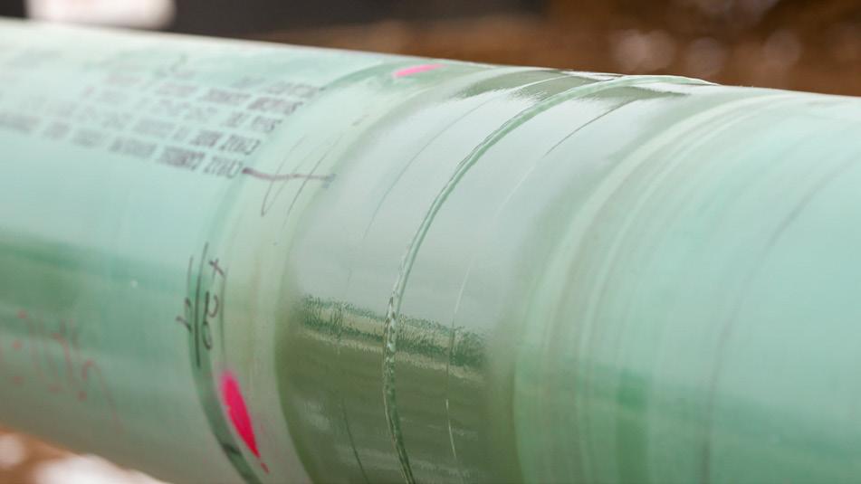
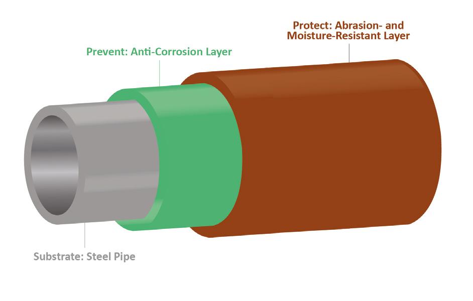
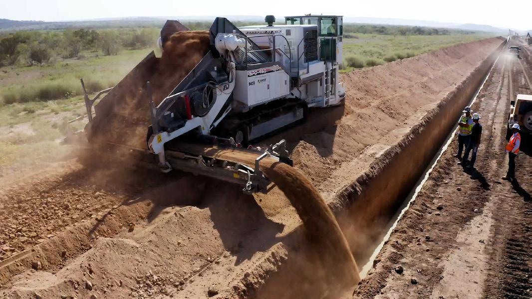
Between inland gas extraction sites, peak shaving facilities and coastal import/export terminals, raw and processed natural gas requires a lengthy system of pipelines to transport supplies often hundreds of miles. These underground pipes require significant protection from
corrosion to avoid deterioration that could lead to reduced pipe wall thicknesses and the potential for catastrophic leaks. That includes the corrosion protection applied to pipes in a shop environment, as well as the coatings used in the field to cover the girth welds that are made as installers fasten pipes together.
Today’s natural gas pipelines face more challenging soil environments with even harsher, rockier, and wetter terrain than before. As such, the pipes can benefit from using better performing coating materials than the conventional fusion-bonded epoxies (FBEs) that have typically been used. The more robust coatings offer improved damage prevention and moisture tolerance.
As an example, a moisture-resistant overcoat (MRO) applied over top of a conventional FBE exhibits exceptional damage prevention and moisture tolerance for challenging installations (Figure 6). The dual-layer coating system offers a combination of corrosion prevention from the first layer and protection of that coating by the second layer. The topcoat creates a moisture barrier that discourages water from penetrating through the coating to reach the anti-corrosion layer. This damage-resistant layer also resists abrasion, helping the coating avoid many of the scrapes a pipe may encounter from handling to installation, including the rigors of horizontal directional drilling (HDD) and backfilling.
This newer MRO coating is a perfect example of why EPCs and owners need to continue working with their coatings
suppliers to stay abreast of new technologies and update specifications accordingly.
For coating the girth welds that occur at every joint where new pipeline sections are connected together, installers have the option of using a powdered FBE that matches the native coating already applied to the pipe or a liquid epoxy that is made from the same chemistry (Figure 5). Powder from materials can be optimised according to the service condition required, including using a dual-layer system with an anti-corrosion layer and a moisture and abrasion-resistant layer. There are also powdered FBEs with low application temperature characteristics that make them ideal for cold-weather installations. On the liquid side, two-component, ultra-high-solids, amine-cured epoxies are available that provide outstanding resistance to impact damage, abrasion, chemical immersion, and cathodic disbondment.
With corrosion a constant threat along the entire pathway from extraction sites to terminals, ensuring safety and longevity in LNG operations means choosing the optimal coating solutions to enable better outcomes. Doing so will help LNG asset owners and operators realise the longest lifespan possible for their investments.
Success begins by shoring up specifications. Owners, EPCs, and coating suppliers should all convene early in the project planning process to review all the operating variables associated with each asset to be coated. They can look to legacy specifications for guidance, but they should also consider newer solutions that could offer better long-term performance. New specifications should include universal coatings that ensure quality, colour, and performance consistency, so modular parts built in different areas of the world can be assembled successfully on site with no obvious signs the components were produced elsewhere. Consistency enables uniformity – which are both key characteristics owners are looking for when operating around the globe.
Following the guidelines discussed in this article will help LNG asset owners and specifiers select the optimal high-performance protective coatings for their operations as they work diligently to combat CUI, protect massive storage tanks, and safeguard pipelines and other infrastructure assets.
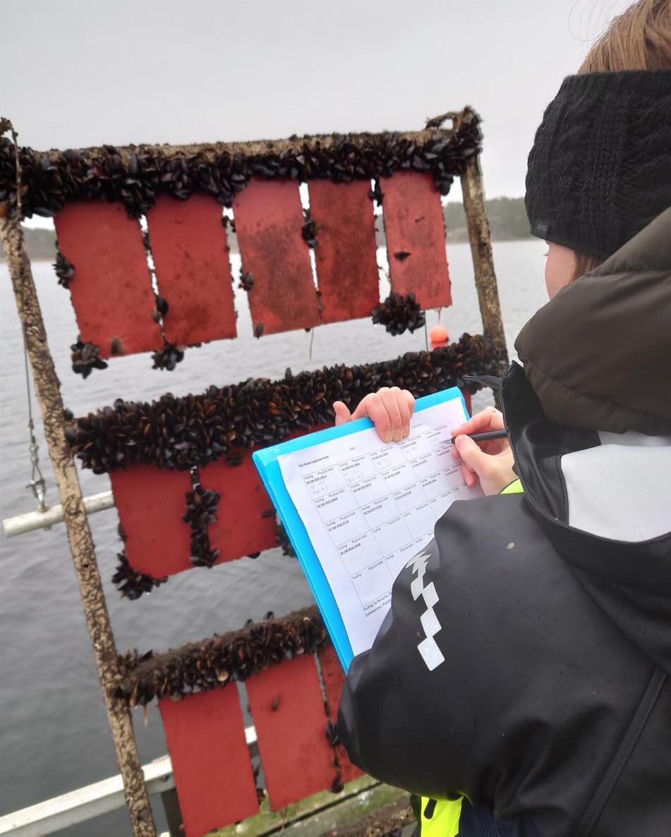
Per Svensson, Sales Director, I-Tech AB, outlines the not-so-secret agents protecting the LNG carrier fleet from biofouling.
n the past Century, the international shipping industry has undergone several evolutions. The energy sources used by ships have progressed through sail to steam to diesel engine, and now renewable energies are starting to come into the fuel mix. Ship designs have been modified in the quest for achieving greater efficiency and competitiveness and clean technology use by the industry has grown significantly.
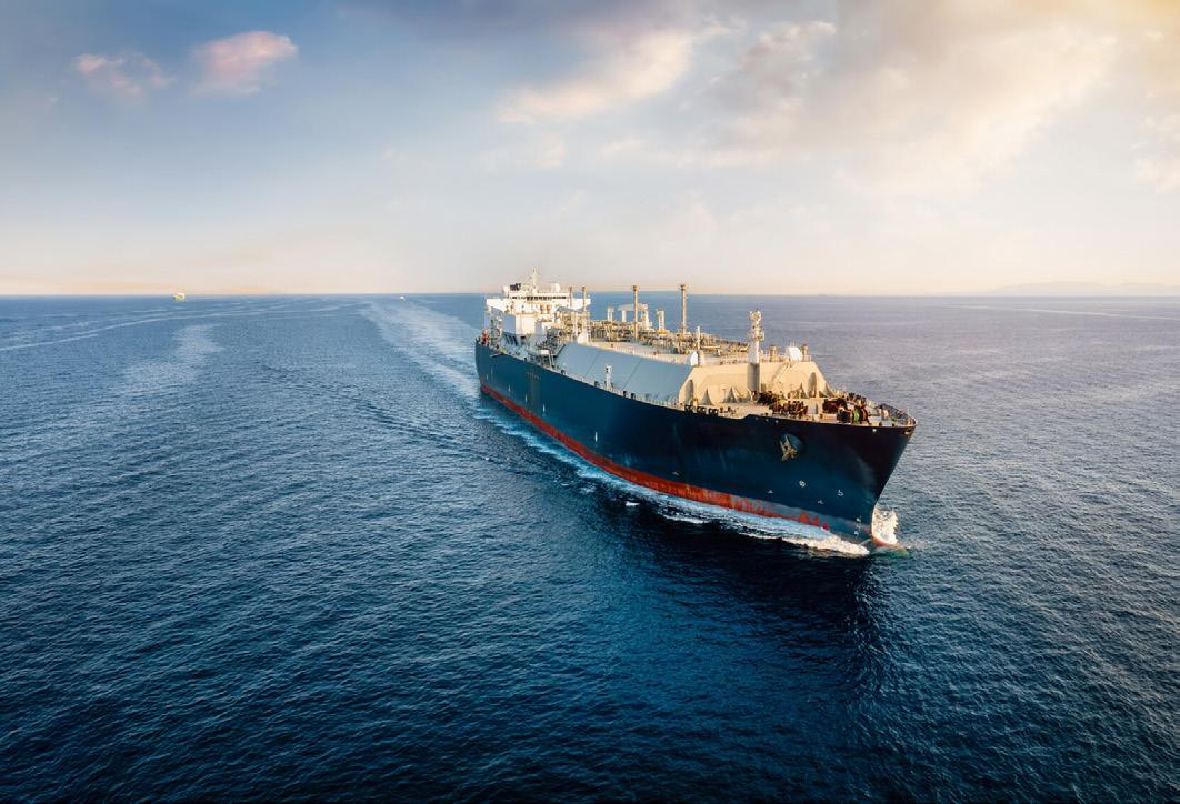
Alongside these changes, in the past decade, the LNG carrier fleet has grown rapidly to meet increasing demand. With LNG trade volumes reaching 549 billion m3 in 2023, a higher number of tankers have hit the water to satisfying growing consumer demand in recent years. In fact, the number of LNG storage vessels worldwide has more than doubled from a total of 360 vessels in 2010, to 772 vessels in 2023.1

However, one thing that has not changed in several millennia is the risk that ships face from biofouling. This is the well-known and much encountered global community of biological marine invaders that settle and grow on the submerged surfaces of ships.
For the LNG carrier fleet, biofouling, particularly barnacle fouling, is not only bumping up fuel bills when vessels are in operation, but it is also a growing issue for many shipyards located in warmer waters that construct and fit out LNG carriers.
What the ships of the past have in common with the ships of today is that they spend their working lives sailing through, or sitting in, a watery soup of aquatic organisms. The composition of this watery soup varies from area to area on a global scale. The strength of the biofouling is determined by several varying factors including light levels, water temperature, and pH. However, one thing is certain: with global water temperatures increasing, the biofouling soup is only getting more flavoursome as species flourish under increasingly favourable conditions and the outer limits of ‘biofouling hotspots’ expand.
For the LNG-carrying fleet, managing the effect of hull biofouling on vessel performance when in active service is a significant challenge and an expensive problem. A biofouled hull increases the fuel used by a ship due to creating hydrodynamic drag on the hull, and this introduces the needs for a ship to burn more fuel to maintaining a set speed or, if a ship is operating on fixed shaft power, it will lose speed.
LNG carriers spend long periods of time in waters with a high intensity of biofouling organisms. Once in active service, their typical trading routes are through warmer waters posing a high biofouling risk. LNG carriers also spend periods of time static in high-risk biofouling hotspots off the west coast of Africa, the Middle East, Southeast Asia, and Australia during gas up and cooldown periods necessary when loading the cargo, which increases their biofouling risk significantly.
However, the type of biofouling that accumulates on the hull can determine the severity of the fuel penalty. Hard fouling species exert the greatest negative influence on bunker fuel consumption and can create a higher level of speed penalties when a vessel is in service. This is because hard-shelled species attached to the hull create greater hydrodynamic drag compared to soft fouling marine species.

Although barnacle fouling can only occur when a ship is idle or operating at low speeds, as soon as larvae have the chance to attach, they glue themselves to the surface and create a calciferous bottom plate using one of the strongest glues in nature. From this glued baseplate they build up walls around their soft body to form a volcano-shape shell.
However, it is not just when vessels are idle in or around ports during their day-to-day operations that they are exposed to the risk of accumulating barnacle biofouling on the hull. It is also a problem that is extremely prevalent in shipyards, particularly for vessels with long outfitting periods, such as LNG carriers.
As global water temperatures increase and global ‘biofouling hotspots’ intensify, newbuildings at the world’s major shipyards in hotspot areas will be exposed to a greater risk of biofouling during the outfitting process. Since LNG carriers have extended outfitting times more than 12 – 18 months and are often built in yards located in warmer waters, such as those off the coast of South Korea, this vessel type is often at a high risk of biofouling, particularly barnacle fouling. These newbuild vessels during outfitting are effectively barnacle magnets.
During the outfitting period, a significant area of the underwater hull and niche areas are exposed to biofouling species. This can have a significant impact on a newly applied hull coating and on a vessel’s performance in sea trials, with barnacle biofouling having the greatest negative effect.
Readers may think, but surely, a vessel that has a good antifouling coating applied at the newbuild stage is already protected?
It is well-known that liquid antifouling coatings are used across most of the global shipping fleet for the purposes of biofouling prevention. So, it would be entirely sensible to think that the in-situ antifouling coating that was applied before the vessel was floated would already be working to protect the hull from biofouling, but this is not the case.
The antifouling coatings that are usually applied on a newbuild ocean-going vessels are designed to last for 60-months. However, they are designed to work under dynamic conditions. The complex chemistries and biocide release mechanisms (or slippery surface in the case of foul
release coatings) of these coatings do not work so well when a vessel is static, particularly when a vessel is sat idle for months at a time. For example, biocidal coatings used on 95%+ merchant vessels are designed to dissolve or ‘polish’ away over time, delivering the biocide when water flows across the hull surface.
Without the flow of water, those coatings are likely not able to offer the superior hard fouling prevention performance required for long static conditions in warmer waters with high concentrations of biofouling species.
Therefore, if a vessel does not have adequate protection from an antifouling coating layer that can release biocide with little or no water flow, when the vessel goes for its speed trial, the hull may be full of biofouling and the speed trial is affected.
This is a significant challenge for shipyards, particularly those located in warmer waters. The vessel needs to undergo speed trials and be delivered to the owner with a foul-free hull.
Cleaning the hull before the speed trial and delivery to the owner is one option; however, cleaning practices can deplete the thickness of the antifouling system. This is not ideal since liquid antifouling coatings are applied to a specific thickness related to the specifics of the vessel’s operations such as design speed and activity. Therefore, loosing layers of antifouling coating will shorten the performance life of that coating.
Also, for vessels with barnacle fouling, more abrasive cleaning techniques are required since there is a risk that over a period of time a barnacle’s shell could cut through the

coating down to the steel hull. Therefore, undertaking cleaning to remove established barnacle fouling could pose a risk of significant damage to the coating where areas of the coating are left exposed to biofouling more than others. This can be the case when barnacle fouling is partially removed but the barnacles calciferous base plate remains attached to the vessel hull where biofouling can flourish.
When it comes to biofouling, control protection for vessels that have long outfitting periods requires further protection in the form of an extra protective layer of antifouling coating, applies as a final layer.
The type of antifouling coating used for this purpose would have the characteristics of a high polishing rate so that biocide would be continuously released when in static conditions, without the need for the flow of water to polish away coating layers exposing fresh biocide.
This additional layer is designed to protect against fouling during the entire outfitting period. By the end of this period, the one-layer coating should be almost polished away in its entirety, exposing the main antifouling system for when the vessel enters service.
For barnacle fouling prevention, the antifouling technology Selektope is used in many antifouling coatings intended for outfitting biofouling prevention. This is due to its highly selective precision, efficiency at extremely low concentrations and sustained performance under static conditions. For this reason, it is being adopted by many of antifouling coating manufacturers as a technology that acts as barnacle fouling insurance.


It protects the hull in long static periods during outfitting, but also, when included in the 60-month antifouling coatings, provides insurance that a vessel can idle for long periods of time without suffering the negative consequences of barnacle fouling. Which is very important for LNG carriers and their trade patterns.
Selektope is an organic, non-metal active agent that prevents barnacle fouling by temporarily activating the swimming behaviour of barnacle cyprid larvae, repelling them from the hull surface. As it is an organic compound, it is metabolised by the barnacle larvae, and they return to normal function after a few hours.
This first-of-its-kind antifouling technology caught the attention of coatings suppliers in the early stages of its research and development. To-date, several products have been launched onto the market and the number of Selektope-containing coatings being sold by different manufacturers is increasing y/y. Selektope is playing a vital role at shipyards to protect LNG carrier hulls from barnacle fouling during extended outfitting periods. As such, the use of the technology in this application has significantly expanded in the past five years.
For vessels in operation, with over 95% of vessels using biocidal antifouling coatings these form the first line of defence against biofouling and will continue to do so into the future.
As the first line of defence against biofouling for most marine vessels, biocidal antifouling coatings play an integral role in the decarbonisation challenge of the global shipping industry and in mitigating biosafety risk from commercial vessels, in the short and mid-term future.
The not-so secret agents contained within marine antifouling coatings are keeping biofouling at bay and, in doing so, mitigate high costs that would otherwise be incurred from excess fuel use, carbon taxes and maintenance costs.
Currently, there is increasing regulatory pressure to reduce the use of biocides in antifouling coatings. As such, great innovative strides are being made by coatings manufacturers to meet this challenge using the limited number of marine biocides that are approved for use and at the lowest concentration possible while ensuring that coatings continue to deliver the biofouling prevention protection that the global shipping industry requires. Selektope, since it is used in extremely small concentrations in the paint, helps antifouling coating manufacturers to meet this challenge and helps keep ships free from barnacle fouling, no matter the biofouling soup strength and no matter the time spent static.
As one of the not-so-secret antifouling agents below the waterline, Selektope is part of a highly regulated crew of biofouling banishing biocides – without them, LNG carriers would be much more fouled that they are today, both in the shipyards during outfitting and when in operation, sailing in and out of biofouling hotspots.
1. ‘Number of liquefied natural gas storage vessels worldwide from 2010 to 2023’, Statista, (19 August 2024), www.statista. com/statistics/468412/global-lng-tanker-fleet
Stavros Sklavounos, Hull Performance Solution Manager, Hempel, directs attention towards how companies can get off the back-foot in the race to reduce emissions from LNG carriers.
or steam turbine LNG carriers, which represent a sizeable proportion of the existing global LNG fleet, slow steaming as a strategy to reduce vessel emissions simply is not an option due to the technical constraints of their propulsion systems. These behemoths pose a challenge for owners and operators because they are amongst the oldest, least efficient, and therefore most expensive gas carriers to operate – they are both too young to scrap and too old to justify significant retrofitting. Crucially, given that this class of vessels

makes up around 27% of the global gas fleet, they are needed to meet the still insatiable global demand for LNG, which shows no sign of abating within their lifespan.
All LNG carriers use boil-off gas (BOG) from their cargoes to help propel them. However, compared to newer designs, steam turbine LNG carriers produce significantly more BOG, and the boil-off rate remains constant regardless of operational speed. This means that slowing down – a strategy that can reduce fuel consumption and emissions for other ship types – extends the journey time
for steam turbine LNG carriers, which causes more BOG to burn.
In other words, while slow steaming typically reduces fuel consumption in most vessels, for steam turbine LNG carriers, the longer the voyage, the more gas is lost to BOG. This in turn has to be burned to maintain propulsion or led to a gasification unit for safety purposes and wasted as a potential energy source. This means that
even though the ship is moving slower, it is consuming more gas over a longer period or wasting it. Because these vessels consume more gas as the voyage time increases, slow steaming paradoxically leads to higher emissions.
For charterers, who ultimately foot the bill, the result is counterproductive: increased emissions and operating costs, which stand in direct opposition to the goals of the International Maritime Organization’s (IMO) Carbon Intensity Indicator (CII) and Energy Efficiency Existing Ship Index (EEXI) regulations.
With the EU’s Emissions Trading System (ETS) now also expanded to cover maritime shipping and the FuelEU Maritime regulation requiring ships to reduce the carbon intensity of energy used on board which came into force in early 2025, many charterers are now forced to account for these increased operational costs too. These regulatory requirements will further impede the competitiveness of older, less efficient vessels, and steam turbine LNG carriers are under particular scrutiny, even though LNG-fuelled vessels face lower penalties than ships burning conventional fuel oils.
For charterers and operators of these vessels, then, focusing not just on EEXI and CII performance but on the impact of emissions reductions solutions on the vessel’s reference speed (Vref) specifically may be the trick to keeping up with the pack, according to hull coatings manufacturer Hempel.
It all sounds quite complicated, but through extensive analysis and testing with customers, it is clear that operators of steam turbine LNG carriers have little choice but to apply propeller shaft power limitation (ShaPOLi) in order to reduce their emissions in line with EEXI. Applying a propeller shaft limitation cap (and therefore a cap on its emissions) does ensure compliance, but the trade-off is a speed loss of around 2 – 2.5 knots. This quickly adds up to additional transit days, increased operational costs and potential failure to meet charter party requirements.
A vessel’s Vref is the speed it can reach under specific conditions, such as a certain draft or engine load. Vref is used to calculate an EEXI, the IMO’s framework for assessing a vessel’s designed energy efficiency. It takes into account a vessel’s engine and auxiliary engine power, transport capacity, and reference speed.
Owners and operators need to consider innovative solutions that minimise the increase in power required due to hull and propeller deterioration over time. A high-performance hull coating can partially offset the impact of ShaPOLi in a single dry-docking and ensure that it maintains its performance throughout the drydocking cycle. This can reduce the sailing times and subsequently the reduce the absolute BOG amount on a given voyage route.
There is a critical need for shipowners to maintain commercial viability while achieving compliance with
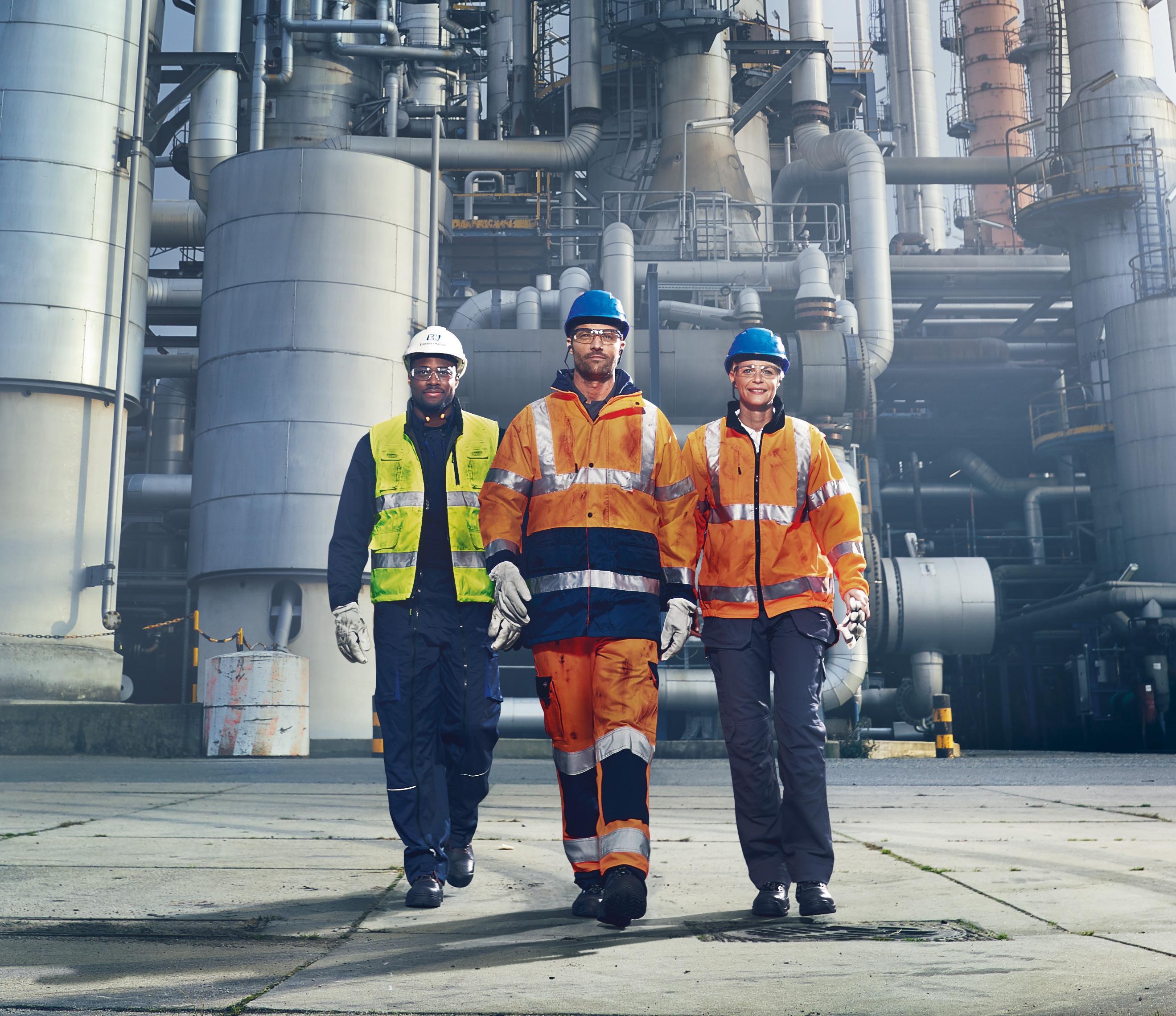
In the oil and gas industry, ensuring highest safety and plant availability is crucial, while achieving decarbonization goals has also become a critical imperative. Our comprehensive portfolio and expertise enable process improvements that increase operational reliability and move us towards net zero targets.
environmental regulations. Hull coatings offer one of the most effective ways to improve a ship’s operational performance, reduce emissions and mitigate the effect of ShaPoLi in a vessel’s Vref without propulsion retrofitting. Advanced silicone-based hull coatings in particular, such as Hempel’s Hempaguard, deliver immediate performance benefits. This is because the surface properties of silicone coatings significantly reduce frictional resistance as the vessel moves through water, thereby reducing the amount of energy required to propel the ship. At the same time, this specific coating type optimises biofouling management on the hull throughout the whole service period between mandatory dry dockings. This results in lower fuel consumption, fewer emissions, and improved speed-to-power ratios.
Hempaguard in particular offers a 2% increase in Vref following application in dry dock, providing immediate operational improvements. The company’s coating has been applied to more than 4000 applications and is market validated for its performance claims and decarbonisation efforts by a classification society — specifically, DNV.
Importantly, for vessel operators, as well as charterers, the impact of a hull coating on emissions performance can be measured and monitored.
Hempel’s approach to emissions reduction is rooted in data. As part of its role as a marine coatings provider, it has developed tools that enable shipowners to calculate the impact of a coatings upgrade on their vessel’s emissions and efficiency. By analysing factors such as the out-of-dock power gain and speed loss percentage, owners can make informed decisions based on accurate data about the ROI and environmental impact of different hull coatings. These reports allow customers to compare their current coatings with potential alternatives, providing a clear picture of how a coatings upgrade can improve CII compliance and reduce overall operational costs. It is recommended that shipowners to consider multiple options before committing to a specific coating product, taking into account the total cost of ownership, expected fuel savings, and potential benefits in daily charter earnings. This data-driven approach helps shipowners not only comply with regulatory requirements but also improve the commercial prospects of their vessels.
Hempel’s System for Hull and Propeller Efficiency (SHAPE) monitoring tool, which is based on ISO 19030 principles, helps shipowners track the effectiveness of their hull coatings in real-world conditions. These tools measure key performance metrics such as fuel consumption and speed loss, enabling shipowners to adjust their maintenance schedules and operational strategies to ensure continued compliance with CII and EEXI benchmarks. Customers use SHAPE as an evidence base for decision-making and for documenting vessel’s performance and maintenance measures implemented.
The validity of the impact assessment is assured through a comprehensive analysis of the vessel’s operation. It does not only take speed, activity, and water temperature into account, it also looks at how these factors are interrelated and how they develop over time. The analysis includes a recommended paint system specification for the vessel type in question, an LNG vessel, defined for standardised trade routes. It is based on an investigation of the operational flexibility requirement (i.e. variations in speed, idle periods, and time spent in warm waters), the risk of fouling, and the risk of mechanical damages due to frequency of canal transits, ice trading, ship-to-ship operations, and berth conditions.
By applying the system to a steam turbine LNG carrier with ShaPoLi, Hempel demonstrates that due to the out-of-dock performance improvement as a result of the Hempaguard hull, it becomes possible to partially offset the speed reduction from the ShaPoLi implemented to attain the required EEXI. This can enhance the vessel’s Vref by up to 2%.
Furthermore, a very minimal average speed loss is experienced over the five year dry docking down to as little as 1.2%, as opposed to the market average antifouling coating – even if the vessel undergoes extensive idle periods, changes trading patterns, or has to slow steam. These coatings are designed for zero cleanings over the service periods, thus the owner and/or charterer also benefits from uninterrupted trading operations, eliminating the potential for off-hire costs, and ensuring continuous vessel availability for service.
In the face of mounting environmental regulations and increasing market pressures, LNG shipowners need practical, cost-effective and proven emissions reduction solutions to maintain competitiveness. Steam turbine LNG vessels, in particular, are facing critical challenges due to their inherent limitations, but advanced hull coatings offer a viable way to reduce emissions and improve efficiency. By investing in high-performance hull coating solutions LNG carriers can achieve power savings of up to 6% right after application, whilst minimising the power penalty due to hull deterioration over the service period. This can add up to approximately 19.5% less power required over the service period, compared to market average self-polishing coatings (SPCs). For steam-turbine LNG carriers, this equates to an ability to maintain their place in a competitive global market.
With the regulatory landscape becoming ever more complex and LNG demand continuing and likely increasing in the near-term, the need for energy-saving solutions that do not compromise operational performance is greater than ever. Hull coatings upgrades offer a quick, non-intrusive method for steam turbine LNG carriers to remain viable in the face of increasing emissions costs under EU ETS and FuelEU Maritime, while also boosting their commercial appeal through improved speed and fuel efficiency.
Riyaz Ali, Emerson, USA, explains how a properly specified valve positioner reduces maintenance, increases uptime, and cuts operational costs, especially instrument air consumption.
NG facilities and pipelines depend on precise and reliable flow control to maximise production and avoid unplanned outages. A control valve with a smart positioner makes this possible, quickly adjusting the valve position as necessary to compensate for changes in process conditions, air supply pressure, and variable valve packing friction and dynamics.
The net result is a control valve that moves to its commanded position and stays there, despite a myriad of disturbances, with optimised consumption of instrument air. Digital valve controllers have taken the capabilities of a valve positioner to new levels, but not all designs are the same, with overall robustness and performance varying significantly.
This article discusses some key digital valve controller design features to improve valve performance, while generating significant reductions in instrument air consumption, maintenance costs, operating costs, and process uptime.
The key task of a positioner is to compare the actual valve position to the commanded position, and then adjust the valve as necessary to keep the process flow at setpoint. This continual adjustment is necessary because there are many external influences that can affect valve movement. For example, changing process conditions might drive valve position away from setpoint, valve packing friction may change over time, the valve might be sticking and becoming harder to move, the actuator may start leaking pressure and losing torque, and other conditions can also cause issues.
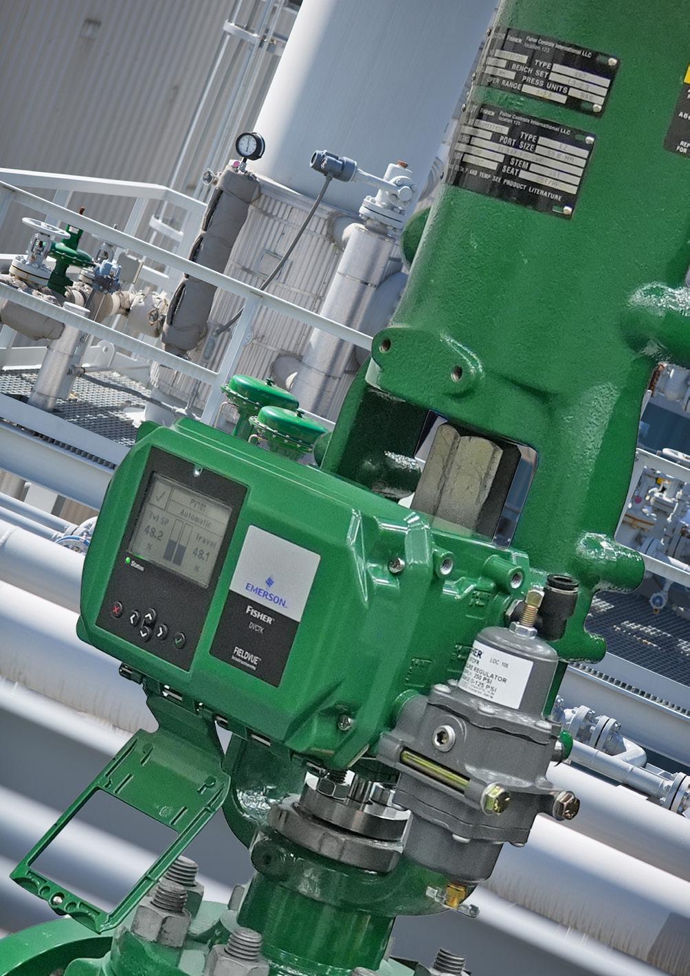
1. Digital valve controllers, like this FisherTM FIELDVUETM DVC7K Digital Valve Controller from Emerson, employ a variety of sensors and electronics to ensure even very large valves reach their commanded position despite variable interferences.
Despite all these factors, the positioner must compensate to keep the control valve at its target setpoint position.
Digital valve controllers (Figure 1) have significantly enhanced valve positioner capabilities with diagnostics. The positioner is now even more precise, and it offers various embedded sensors to detect and then alert plant personnel to developing problems. It also monitors and stores performance data for troubleshooting and analysis.
While all these features certainly improve control valve performance, there are still other design aspects that can yield significant savings if the correct valve controller is specified and fully utilised.
To facilitate very fast response, many valve controller designs use a mechanical balance technique, also referred to as a force beam, connected to the valve position sensor. When the slightest error is detected, the mechanism will move, varying the signal to a high gain pneumatic relay, which adjusts the actuator air pressure to move the valve to the correct location. Since the force beam acts on very small changes to commanded position, a natural result of this design is the valve controller tends to bleed air, even when the valve is not moving. This consumes instrument air and can be particularly problematic and costly if the valve is at a remote location and uses natural gas as the actuating medium instead of air (Table 1).
A simple solution to this problem is to replace the standard valve positioner with a low bleed model. As Table 1 shows, a low bleed valve controller using air for actuation saves some money, but these savings can accumulate when evaluating various valves in an area, especially if the total air usage requires a larger compressor. The savings associated with replacing an older style pneumatic positioner are still greater since those units bleed air at rates higher than that shown in the table. It is also worth noting that a valve with higher outlet pressure will bleed more air.
When the valve is actuated by natural gas, the savings are considerably higher. The lost gas itself is worth nearly US$800/y, and the additional savings associated with reduced methane emissions and carbon credits add to that figure. Many countries now mandate positioners and controllers with lower air consumption for equipment actuated with natural gas as part of greenhouse gas reduction efforts, so regulatory compliance is another advantage of low bleed equipment.
If low bleed is good, is zero bleed better? The answer is probably not. There are a few different digital valve controller designs, including spool relay valve, mechanical balance beam, and piezoelectric. Spool relay designs have been around for decades,
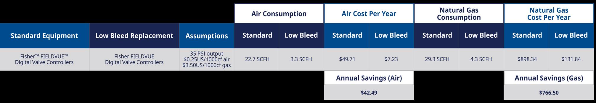
but they are sensitive to air quality and tend to have slower response, so that design is becoming less common as they are replaced with mechanical balance beam and piezoelectric designs.
Mechanical balance beam designs are less sensitive to air quality and incorporate a very sensitive balanced beam that responds to the slightest error. This allows the digital valve controller design to respond very quickly to even slight changes in commanded position, which provides precise, high-speed response. However, even the low bleed design does bleed a small amount of air when in the neutral (balanced) position, but this air can be used to maintain a minimal pressure inside a digital valve controller housing to prevent intrusion from any outside corrosive plant air. In some applications, such as with single or double-acting piston actuators, the bleed air can be infused into the piston housing for the same purpose.
Piezoelectric designs utilise a piezoelectric-driven on/off module that can either pressurise or vent the air signal to drive valve position. This design is essentially an on/off controller that relies on a small error deadband to drive response when the control signal changes. This can limit its sensitivity to small changes in valve command signal due to in-built dead band to avoid chattering, but it does have the advantage of essentially zero bleed when the valve is in the neutral position.
But the reality is that the low bleed vs zero bleed discussion is largely moot. The difference in total emissions between the designs is quite small, but even this rarely comes into play since these bleed rates apply only when the valve is not moving. Most control valves are continually in motion, adding air to the actuator or venting it off. Under these conditions, the total air usage depends on the size of the actuator and the amount of
movement required, so the positioner design regarding air consumption at static conditions becomes insignificant. Therefore, the only time there is likely any difference at all in bleed flow will be when the valve is placed in manual control, typically an infrequent occurrence.
On the other hand, there are many positioner design features that absolutely do matter because they can generate meaningful savings. These include:
z Valve performance: Users want a positioner that reliably positions the control valve quickly, accurately, and consistently. Tight control valve positioning often yields improvements in process stability and product quality, creating tangible productivity increases. Saving a little money on a poorly performing positioner often costs far more in the long run.
z Sensors and diagnostics: Digital valve positioners use linkageless, non-contact valve position sensors to minimise mechanical losses, and they incorporate sensors to monitor many aspects of the control valve assembly. They also measure supply air pressure, drive signal pressure, air mass flow, travel deviations, stroke time temperature cycle count, and other parameters. From that data, the device can detect packing problems, process plugging, and air leaks long before the control valve performance is impacted. Fixing a valve problem before it affects the process further improves process reliability and uptime.

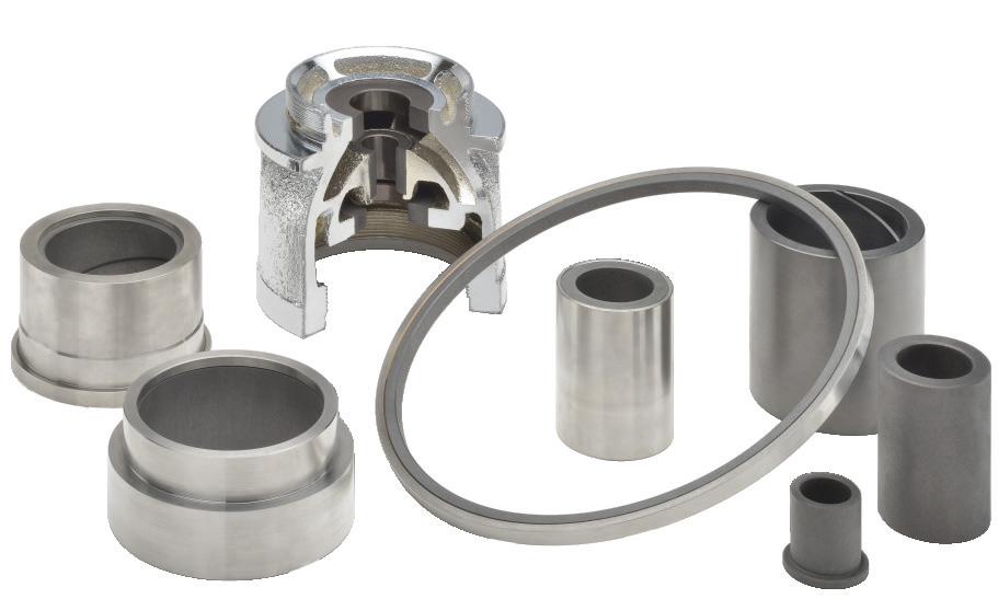
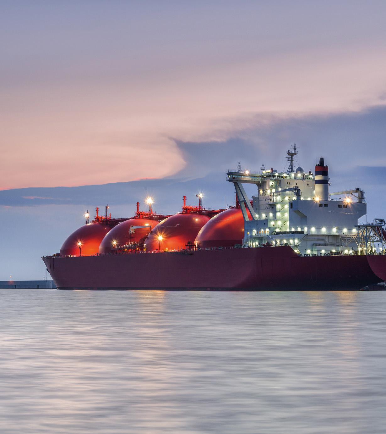
z Remote monitoring and alerts: Embedded connectivity, using a wide variety of protocols, allows the digital valve controller to communicate potential problems to maintenance staff well in advance. Saved stroke profiles and data analytics empowers plant personnel to continuously monitor key valves, and to recognise and resolve issues before production is impacted.
z Safety and SIL-rated features: For critical safety valves, a high diagnostic positioner can improve safety reliability and extend SIL interlock test intervals, maximising production. These devices also enable partial stroke testing, which confirms the valve is operating, without the need to remove it from service.
In addition to selecting a low bleed digital valve controller, users would be wise to investigate all these features and ensure the replacement positioner will deliver these savings. Reduced air or natural gas bleed is valuable, but adding a few months of plant run time, avoiding a single outage, or eliminating needless control valve overhauls can generate even greater benefits.
Selecting the right digital valve controller with diagnostics will improve quality, increase throughput, avoid needless air bleed, and provide reliable operation. However, those savings will be limited if the available digital valve controller positioner data is not fully utilised.
Whenever any control valve is placed in service, it should have baseline tests performed and saved. Examples of baseline tests include the total scan (one scan which includes the valve signature (Figure 2), dynamic error band, and drive signal tests) and step response tests. Baseline test data is invaluable for troubleshooting if problems occur later.
To supplement a total scan (or if one is not available) an X-ray can be done online without taking the valve out of service. This information can be used to focus turnaround efforts on the valves that truly need attention, rather than mass overhauling all the valves, whether they need servicing or not. This saves considerable time, which is critical during a turnaround.
Costs are greatly reduced because servicing requires removing a valve from a pipe and taking it to a shop, which may require a crane or other support structure. Soft parts of a valve are typically damaged when it is opened for inspection, so these require replacement.
In addition to taking a stroke profile, there are three simple digital valve controller alerts that will typically result in significant payback in the long term. Setting up and enabling these alerts is simple enough, and they apply to virtually all digital valve controllers:
1. Enable the travel deviation alert. This alert will alarm if the valve takes too long to reach its commanded position. This alert can flag pneumatic leaks, packing friction problems, and process plugging well in advance of outright valve failure.
2. Enable the air supply pressure alert. This alert will indicate a poor air supply, a plugged regulator, or a significant air leak.
3. Enable the drive signal alert. In normal operation, a valve actuator will run at 55 – 85% of the nominal pressure. If the valve is consistently running outside that range, this can indicate internal problems with the positioner or actuator.
Note that these alerts serve little value if they are not monitored and acted upon. Ideally the valve should communicate these problems to an integrated maintenance management system where they will be automatically flagged for investigation. If such a system is not available, routine walkdowns looking for flashing alert indicators on critical valves can easily be justified.
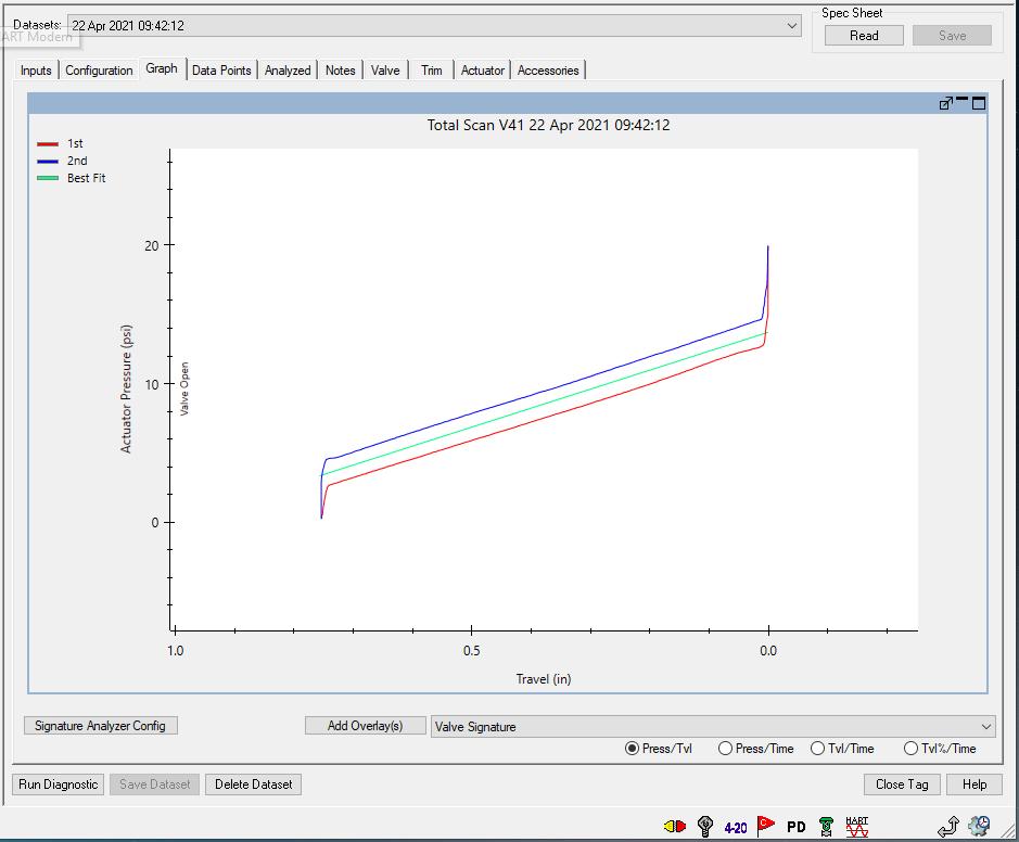
Figure 2. Baseline valve performance information, like this valve signature test, should be captured when commissioning a control valve so it can be compared against future stroke performance to spot developing issues and troubleshoot failing components.
There are many digital valve controller designs available on the market today and prices range considerably. Nearly all promise reliable and precise performance, but their true capabilities vary widely, and selecting the right positioner can dramatically improve plant operations.
When evaluating digital valve controllers, users should look for low bleed models with embedded high diagnostics and built-in sensors. They should also demand models that can communicate critical information to outside systems where the data can be utilised. When properly specified, commissioned, and integrated into a maintenance management system, the payback for choosing the right digital valve controller can be substantial, and it can generate significant cost reductions and improved reliability for any LNG facility.

Mark Naples, Managing Director, Umicore Coating Services, provides insight into how infrared filters can unlock the next level of LNG maintenance.
n an era where the stakes for safe and efficient LNG operations are higher than ever, the shift from reactive to preventive maintenance is not just a preference but a necessity. Embracing more effective maintenance strategies is imperative for any forward-thinking supplier.
Preventive maintenance is transforming the LNG sector. Driven by technological innovation, this approach to plant management enables maintenance teams to make informed decisions based on the condition of the actual equipment rather than fixed schedules. Implementing preventive maintenance strategies can help LNG plants significantly reduce the likelihood of unexpected equipment failures and process disruptions, minimising unscheduled shutdowns and improving overall operational reliability and efficiency.
Cutting-edge infrared (IR) gas detection technologies are at the forefront of this revolution. Powered by precision filters, these sensors enable LNG operators to quickly identify potential leaks and plan maintenance to address them before they become a threat. With unmatched sensitivity and selectiveness, IR sensors offer a powerful tool for enhancing safety in the LNG sector. As this technology advances its benefits are becoming increasingly harder to ignore.
The LNG sector demands nothing short of excellence in terms of maintenance. With complex infrastructure

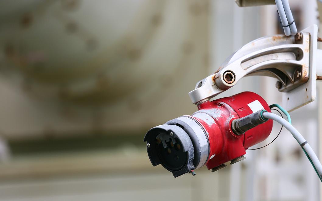
comprising vast networks of pipelines, storage tanks, and processing units, as well as the hazardous nature of the substances it works with, operators in this industry have little margin for error. Even minor leaks or equipment malfunctions can have severe consequences.
Many stages of the LNG production process are prone to the risk of toxic or flammable gases leaking. Although LNG is non-flammable in its cryogenic liquid form, as it begins to warm and vaporise into a gas, this can become an issue.
Failure to keep assets to a suitable maintenance standard could endanger employees, damage assets, and harm overall productivity. LNG facilities handle volatile substances, often under extreme conditions. Any degradation to asset integrity has the potential to expose employees to these substances, presenting a health or explosive risk. Damage may also lead to unwanted substances leaking into the surrounding environment, contributing to pollution and potentially subjecting those responsible to regulatory action.
The potential consequences of equipment failure mean that any LNG maintenance strategy must be capable of detecting even the slightest deviation from standard operations. Traditional maintenance approaches in the LNG sector have relied heavily on scheduled inspections, periodic equipment overhauls, and reactive repairs.
While these methods have served the industry for decades, they are increasingly inadequate in the face of growing demands for efficiency, safety, and environmental responsibility.
Reactive maintenance is naturally not an ideal solution for dealing with equipment quality.
Alongside the fact that it can only take place after an incident has occurred, it also results in unplanned downtime that could cost millions in lost production. Regular scheduled maintenance is more effective but without sufficient data backing risks not being targeted at the areas most in need of repair, resulting in inefficiencies.
Preventive maintenance overcomes these issues with a data-informed approach that aims to address any issues before they emerge. Utilising advanced sensor networks, this method aims to target maintenance activities based on thorough evaluations to ensure the most critical components receive timely attention. By keeping equipment operating at peak efficiency, operators can reduce the risk to staff and infrastructure, minimise unexpected shutdowns, and extend asset lifespans. Subsequently, this significantly reduces the long-term costs associated with emergency repairs, equipment replacement, and production losses. What is more, with the stringent regulations governing the LNG industry, regular, proactive maintenance can help facilities meet and exceed the standards placed on them, avoiding costly fines and reputational damage.
However, implementing a new maintenance strategy can be easier said than done. Maintaining LNG facilities presents its own unique series of challenges, not least
of which is the extreme environments that many plants operate in. From cold temperatures to corrosive marine atmospheres, LNG infrastructure is often exposed to stressful conditions that can mean emerging maintenance problems go unnoticed for too long.
The size and complexity of LNG operations compound this issue, with vast networks of pipelines, storage tanks, and processing units requiring sophisticated monitoring which can prove time-consuming and labour-intensive. With so many critical components, maintenance teams must carefully balance priorities to ensure the most critical systems receive adequate attention while not neglecting other important areas.
Preventive maintenance relies on a combination of predictive analytics and large scale sensor networks, but these sensors must be carefully selected to ensure they can meet the unique challenges of the LNG sector. Recent years have seen businesses begin addressing this with the adoption of several advanced technologies, such as ultrasonic testing, thermography, and vibration analysis. These tools have provided more effective methods for detecting internal flaws in pipelines, identifying hotspots that may indicate equipment stress, and monitoring for signs of wear or misalignment. However, while these technologies have improved maintenance capabilities, they can fall short in terms of providing the standard of precise detection required for truly preventive maintenance in the LNG sector.
The latest frontier in LNG maintenance technology lies in the IR realm. Advanced gas detection systems utilising IR lasers represent a paradigm shift for the industry. This technology enables plants to move from simply monitoring for leaks, to proactively identifying potential issues before they manifest. Such sensors are capable of continuously monitoring for hazardous substances to ensure immediate insights into the precise gas concentrations present.
Armed with a comprehensive network of fixed and portable detectors, businesses can build accurate profiles of their risk level, identifying minute changes in gas composition and concentration, often long before alternative sensors would register an issue. Combined with machine learning and big data analytics, the information from these systems can be used to predict equipment failures and optimise maintenance schedules with unprecedented accuracy.
The most prominent IR gas detectors are based on a technology known as laser absorption spectroscopy (LAS). LAS systems use IR beams to identify trace gas molecules with incredible precision and a wide detection range. By passing an IR beam through a chamber containing an infrared filter, users can detect gas concentrations even in the range of parts per billion, enabling the early detection of even small leaks. This early warning capability is crucial for effective preventive maintenance as it enables operators to address potential issues before they escalate into major incidents.
What is more, these systems maintain their performance even in the challenging environments typically found in LNG facilities, ensuring a supply of reliable data where other sensors may falter. Modern LAS systems are immune to sensor poisoning and interferent gases, granting them the reliability needed to reduce false alarms that lead to costly downtime.
At the heart of these revolutionary sensors are advanced infrared filters, such as those developed by Umicore Coating Services. The filter in a LAS detector prevents all wave lengths of light from reaching the gas being measured for except for those that its specific chemical composition lets it absorb. As a result, the detector benefits from enhanced sensitivity and selectiveness. Changing the filter enables different gases to be detected, overcoming a challenge that can plague other gas detection techniques.
By enabling the development of more sensitive and specific gas detection systems, infrared filters are directly contributing to a shift towards truly preventive maintenance in the LNG sector. With more than 35 years of experience in thin-film design and manufacture, the company has pushed the boundaries of what is possible in infrared filter technology. Utilising the latest analysis and design software, the company can produce bandpass optical filters with a centre wavelength anywhere on the near-IR to far-IR spectrum. This results in highly customisable solutions for gas detection systems that can be tailored to the specific requirements of LNG maintenance.
Real safety in LNG infrastructure requires a comprehensive approach to maintenance that incorporates advanced technologies, data-driven strategies, and a strong focus on safety and reliability. This level of proactive, automated maintenance is no longer just a possibility, but a reality, and the ongoing shift from detection to prevention represents a significant leap forward for the industry.
Preventive maintenance overcomes the existing challenges of downtime and inefficiency, and as environmental regulations on the LNG sector mount, the role of advanced gas detection in conducting preventive maintenance will only grow in importance. The integration of these systems with emerging technologies (such as artificial intelligence) promises to revolutionise maintenance procedures, combining comprehensive infrastructure oversight with real-time data analysis to produce near-instant insights into emerging issues.
The advances being made in detectors and IR filters means that the necessary technology is becoming more affordable and accessible than ever. By providing earlier, more accurate, and more specific detection capabilities, these technologies are unlocking new levels of safety, efficiency, and cost-effectiveness in LNG operations. As companies like continue to push the boundaries of what is possible in infrared filter technology, the future of LNG maintenance looks brighter than ever.
LNG Industry recently spoke to Adam Prestidge, Executive Vice President and Head of Business Affairs at Glenfarne Energy Transition, about the company’s latest projects and the growing importance of LNG.


Q1. What is the latest update with Glenfarne’s LNG projects, Texas LNG, and Magnolia LNG?
Overall, Glenfarne has had a very successful year. Despite a challenging US regulatory and political environment, both Texas LNG and Magnolia LNG remain in ready state pending the resolution of their respective regulatory matters, which we expect as early as 1H25. Glenfarne fully sold-out Texas LNG to
incredible partners including EQT, Macquarie, Gunvor, and a highly experienced, investment-grade, global LNG player and appointed one of the world’s top EPC contractors, Kiewit, to deliver the project under a lump sum fully wrapped arrangement.
From an environmental impact perspective, Magnolia LNG is a superior option compared to other greenfield LNG projects due to its 30% lower emissions footprint and its use of existing utility infrastructure. Glenfarne is excited to advance the project in 2025.


Q2. What might make US LNG more attractive to buyers than LNG from other markets?
The US LNG market stands out for many reasons, but perhaps most prominently are its abundance, affordability, and flexibility.
The US is blessed with an abundance of natural gas. The latest data from the U.S. Energy Information Administration estimates the US has nearly 100 years of reserves based on current production. These reserves coupled with the industry’s efficiency and ability to produce at low prices have kept prices affordable for domestic users, as well as importers. Additionally, US LNG contracts are flexible, allowing buyers of LNG to send cargoes to where they are needed most at any given time. These three facts provide buyers and growing economies across the globe with the confidence they need to invest in the US instead of turning to other markets.
Q3. How can government regulators and elected officials work with LNG companies to progress mutually beneficial agendas?
The US LNG industry is at a crossroads. No matter what party is in the White House or controls Congress, the bottom line is that LNG from the US has a positive global impact, particularly compared to LNG from other less stable and more environmentally sensitive locations. The challenges are largely political – whether it is unnecessary tariffs on US LNG which drives importers to other less environmentally friendly exporters, or an inaccurate perspective of LNG’s impact on the environment and gas prices in the US.
US LNG aids the energy transition by providing the flexible fuel the world needs for baseload generation or to backstop renewables. Much, if not all, of the LNG produced in the US comes from associated gas and/or is responsibly sourced, with careful monitoring for emissions and other impacts on the environment. Despite inaccurate and irresponsible studies showing otherwise, natural gas and LNG have been instrumental in improving air quality. In the US, the increased use of natural gas for power generation has displaced dirtier coal, resulting in lower emissions and less air pollution.
The industry needs to do a better job of communicating these points to policymakers by breaking past the politics and focusing on the facts of why the use of LNG is a sensible energy policy decision for the US and other countries.
Q4. How are geopolitical events and tensions affecting demand in the global energy market? What regions are particularly impacted by this?
Geopolitical events, such as Russia’s invasion of Ukraine, have triggered a global energy crisis, underscoring the urgent need for reliable energy security around the world. This is particularly true for Europe, where many countries relied on Russian energy to fuel their economies. The flexibility of US LNG has proven pivotal, enabling cargoes to be sent where they are needed most, and helping mitigate the impact of any projected energy crisis in Europe.
As a result, many countries are now turning to US LNG, which is currently on track to double output between 2024 – 2028 as new terminals come online. This expansion is not only critical from a geopolitical perspective, but also to ensure countries have reliable options from a stable exporting partner. That reliability is essential in shaping energy mixes and meeting the growing electricity demands of the future.
Q5. Tell me about Texas LNG’s ‘Green by Design’ approach. What is this and what is it designed to do?
Glenfarne Energy Transition and Texas LNG are committed to accelerating the global energy transition through the delivery of efficient, environmentally conscious, and affordable LNG. Texas LNG’s ‘Green by Design’ approach is designed to strategically avoid carbon dioxide emissions through the use of electric motor drives, making it one of the lowest-emitting liquefaction facilities in the world.
Once in operation, Texas LNG is anticipated to produce less than half of the emissions of a standard LNG project, making it appealing to global buyers who are especially mindful about environmental impact.
Q6. Across the world, why can we not just build more solar panels? Why is the energy sector investing in LNG?
Transitioning away from legacy fossil fuels is essential to accelerating the global energy shift, but it won’t happen overnight. Today, renewable sources like solar and wind cannot meet growing energy demand on their own due to their intermittent nature.
US LNG allows flexibility for electric grids and their users to self-determine whether renewables or gas-fired power are best from a cost, reliability, and emissions perspective to meet their corporate and national goals.
Q7. What role does LNG have in promoting grid stability and consistent power generation?
Grid stability is essential for ensuring reliable power generation and advancing the global energy transition. One significant barrier to grid stability is ageing infrastructure, which often lacks the capabilities to effectively support the transition to intermittent, renewable energy sources.
US LNG can serve as a critical bridge fuel, capable of meeting the growing energy demand while ensuring grid stability. This gives nations time to update the lack of grid infrastructure to accommodate renewables. Projects like Texas LNG are designed with this in mind and built for the long term. These terminals will play a vital role in advancing the energy transition, helping emerging markets and allied economies make the transition to renewables. We are already seeing previous projections of increased renewable penetration globally including the use of hydrogen be inaccurate and overestimating their impact. Thus, US LNG facilities will be necessary to fill the void continuing to be important to ensuring global energy security for decades to come.
Q8. Any other opportunities Glenfarne is observing across the energy and LNG markets more broadly?
The global LNG market has experienced significant growth in recent years. We are seeing significant LNG infrastructure development across the world and we’re actively conversing with partners and customers across the US, European, Asian, and Latin American countries. As the energy transition continues, US LNG is the best-positioned alternative to easing off coal and oil and accelerating the globe’s shift to renewables.
Paul Hughes, Project Delivery Vice President, and Andy Loose, Vice President for LNG sector, Worley, detail how an FSRU was operationalised in less than nine months to help secure Germany’s LNG supply and reduce dependency on Russia.
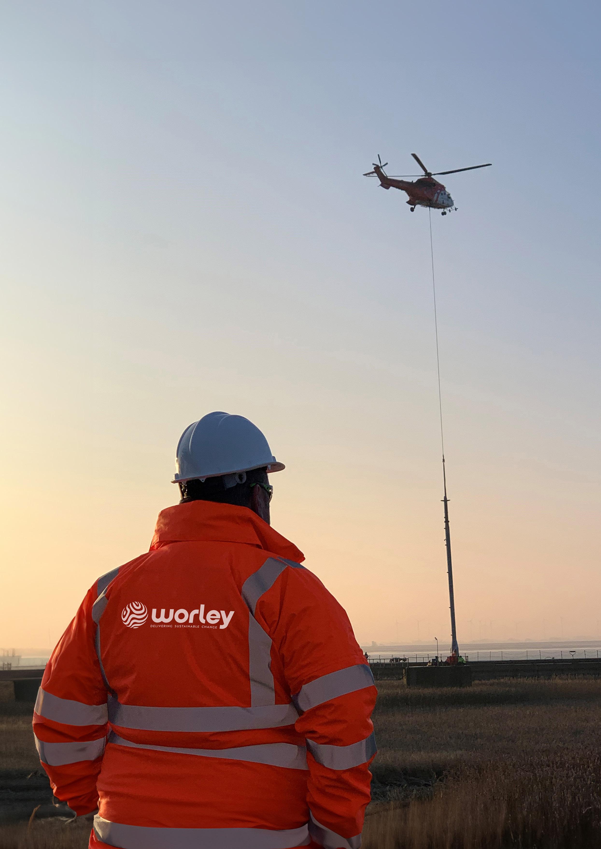
n the year preceding Russia’s invasion of Ukraine, Germany sourced more than half of its natural gas supplies from Russia. As the conflict escalated in February 2022, it set in motion a plan to eliminate its dependence on Russian natural gas.
The task was twofold: Germany had to find sufficient alternative supplies of natural gas to power millions of homes, businesses, and manufacturing facilities, as well as establish the infrastructure to access these alternative supplies by the winter of 2022 – 2023 when demand for heating and power was expected to peak. This triggered an urgent effort to build the infrastructure to import billions of cubic metres of natural gas in a timeframe that few thought possible.
As one of the firms engaged to meet this challenge, Worley had to rethink the traditional sequential approach to infrastructure delivery. In doing so, the company helped demonstrate how working out of sequence – and in close collaboration across the EPC phase – can accelerate project delivery timelines.
Germany is well connected to gas-supplying countries on the European mainland. Previously, it received natural gas through pipelines such as the Nord Stream network beneath the Baltic Sea. However, to replace its natural gas imports from Russia – which tallied over 55 billion m3/y – the country had to import large volumes of natural gas in a different way.
To meet this challenge as the Russia–Ukraine conflict started, the German government acted quickly to charter five FSRUs. These were to be positioned across Germany’s northern coastline to receive LNG from cargo ships, which would then be fed into local gas grids.
This meant natural gas deliveries could arrive in Germany from anywhere in the world, rather than just by pipeline from the European mainland. Once Germany established that the desired FSRUs were available, the primary challenge was to design and construct the marine and land infrastructure required to send gas into the grid in the months that remained before the start of winter in late 2022.
FSRUs were well suited to Germany’s energy security challenge for two key reasons: speed and flexibility.
The units are moored to a marine berth, where they transfer LNG from an LNG carrier in a ship-to-ship configuration using the carrier’s cargo pumps. High-pressure LNG pumps on the FSRU then transfer LNG to a vaporiser at the desired pressure to deliver natural gas into the local gas network for consumption in homes and industries.
In time-critical projects, FSRUs are particularly useful and can be built from scratch or repurposed from existing LNG carriers. In either scenario, an FSRU is almost always faster to engineer, construct, and commission than a fixed onshore storage and regasification terminal. Utilising existing FSRUs that are ready for immediate charter and attaining required permits are often faster compared to fixed LNG import terminals.
Flexibility is the other key advantage of FSRUs. They are fixed in place when operational but can be towed to other locations if the need arises.
In June 2022, Worley was awarded an EPC contract to deliver one of Germany’s five new FSRUs, to be supplied by Höegh EVI. This would be achieved by expanding the existing port in Brunsbüttel on the river Elbe to receive gas from the newly-chartered FSRU.
The goal was to achieve first gas by the winter of 2022 – 2023. There was no concept or FEED phase to define what was needed. The objective was simply to deliver an FSRU to Germany and target first gas during the next winter.
At first glance, an FSRU terminal project (as illustrated in Figure 2), looks relatively straightforward to execute. However, each FSRU project brings unique challenges, and the project at Brunsbüttel was no exception.
Challenges in the construction of a newly planned jetty for the FSRU triggered an early switch to plan, which was to modify the existing oil and LPG import berth at Brunsbüttel port. This would accommodate the FSRU until the new jetty was ready.
Worley also discovered that the local gas distribution network did not have the capacity to accept the FSRU’s full gas send-out rate. The gas distribution infrastructure had to be upgraded, which led to a phased execution approach for the project.
The priority for Phase 1 was to feed up to 3.5 billion m3 of gas into the grid as soon as possible. This involved engineering temporary solutions to operate until more permanent solutions were ready. However, even with the smaller scope of Phase 1, it would have still been impossible to deliver first gas within one year with the traditional approach to delivering energy infrastructure.
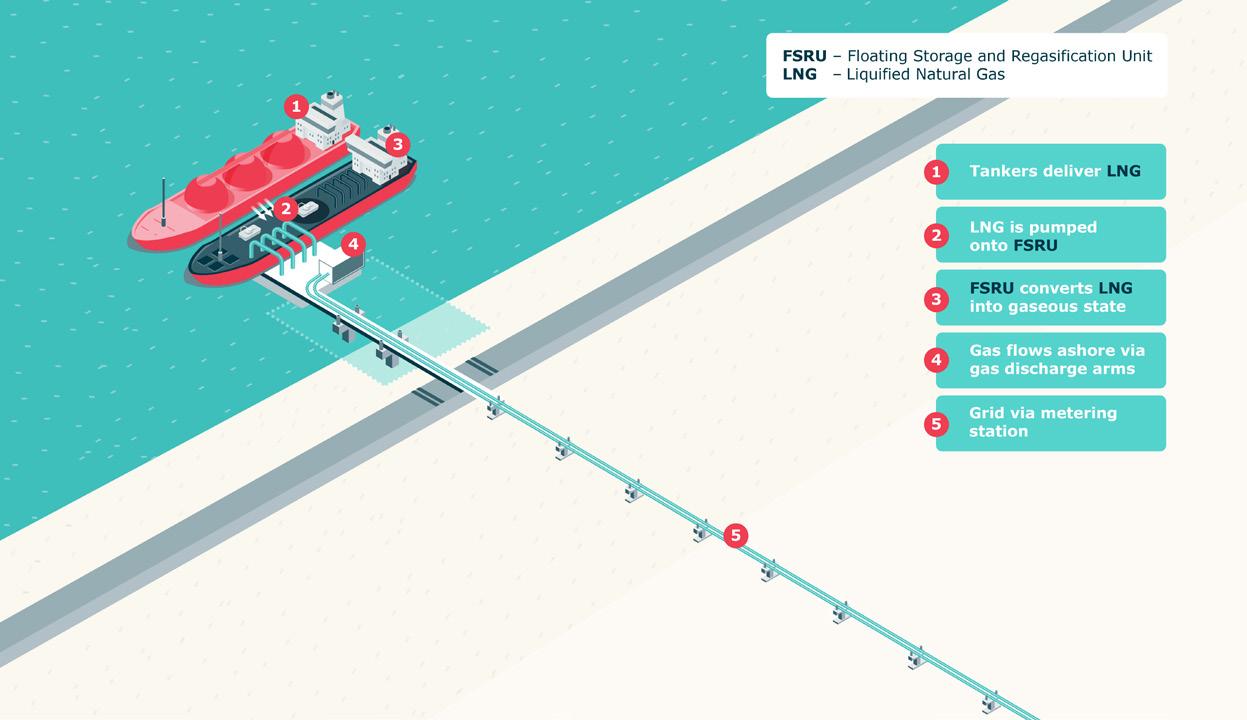
The solution was to take a very different approach to the execution sequence usually seen in other large projects, where the EPC phases followed in a strictly sequential order.
This project instead involved working out of sequence and using backward engineering based on the accessibility of critical components. It also involved innovative thinking such as using helicopters and large Antonov cargo aircraft to deliver key components to the site more quickly.
Procurement was one of the defining challenges of this project, with the greatest impact on the schedule. During the earliest stages of engineering for the project, Worley’s procurement team was already identifying which purchases had the longest lead times and making market enquiries.
For example, high-pressure gas loading arms had been secured for Phase 2 of the project. However, there was no space on the existing quayside berth to install a loading arm for Phase 1. To solve this dilemma, the team quickly ordered a high-pressure gas hose. Whatever the team could buy most quickly took precedence, then Worley’s engineers developed the designs needed to accommodate the items.
The project team also worked closely with the related business, Worley Rosenberg in Norway, to fabricate piping skids and steel structures for the transfer of gas and warm water between shore and the FSRU. This simplified the interface between engineering and fabrication to shorten timelines, and Worley Rosenberg also helped with procurement of critical materials.
While Germany’s natural gas shortfall remained a key concern during the engineering and procurement phases, the project could not compromise the oil and LPG terminals that were already in operation.
Moreover, Brunsbüttel port had been in operation for more than 50 years, so there was limited design information available for the existing facility. The Worley team therefore quickly organised laser scans of the facilities along with a survey of the underground environment.
The stakeholders agreed to establish a temporary berth further along the quay for crude oil offloading. This made it necessary to run a new 24 in. crude oil line for more than
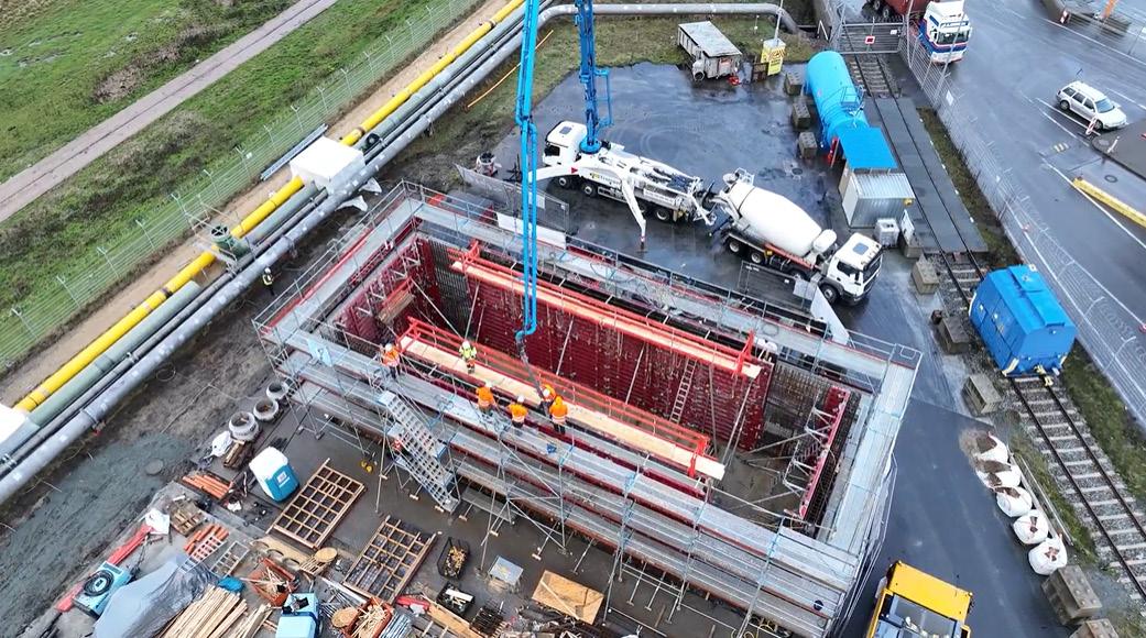
300 m along the quay wall to connect with the new crude offloading hoses.
The design diagram in Figure 4 shows the new water hose tower and high-pressure gas hose tower next to the existing crude oil and LPG loading arms.
The other technical challenge concerned the need for warm water for the regasification process. FSRUs often use their own seawater pumps to provide the water to vaporise the LNG onboard. However, in a northern European climate like that in Brunsbüttel, the water can often be too cold to deliver gas above 0˚C.
Vaporising 3.5 billion m3 of natural gas requires about 60 MW of heat and a warm water supply of over 4000 m3/h.


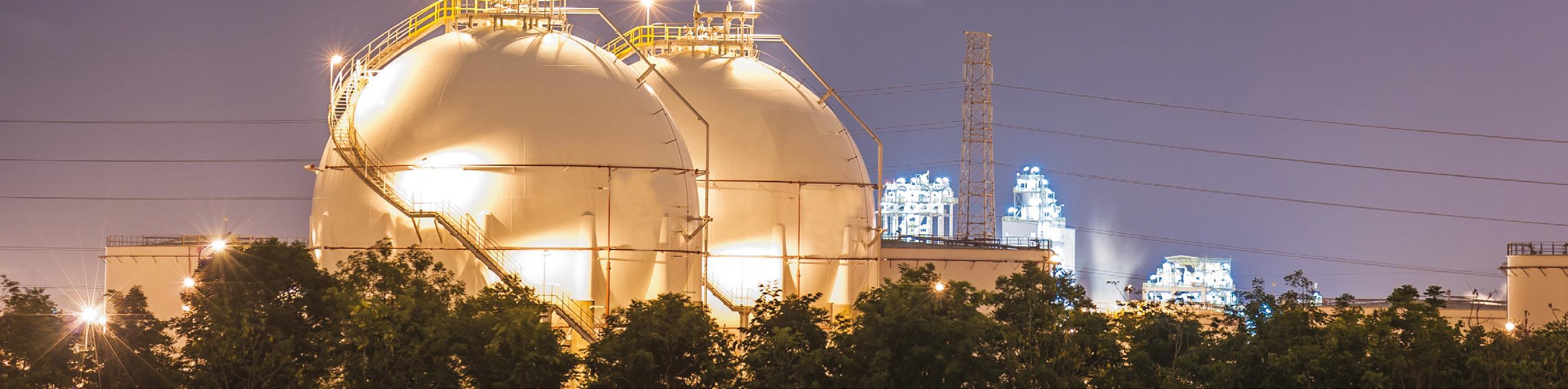
Stakeholders partnered with a local chemical company to gain access to warm water. To deliver this water to the FSRU instead, Worley had to install a large concrete break tank, new variable speed drive pumps and 800 mm dia. glass-reinforced epoxy piping.
The pumps to deliver this water also required power and switchgear. New medium voltage equipment was not available in the timeframe for Phase 1, so the Worley team
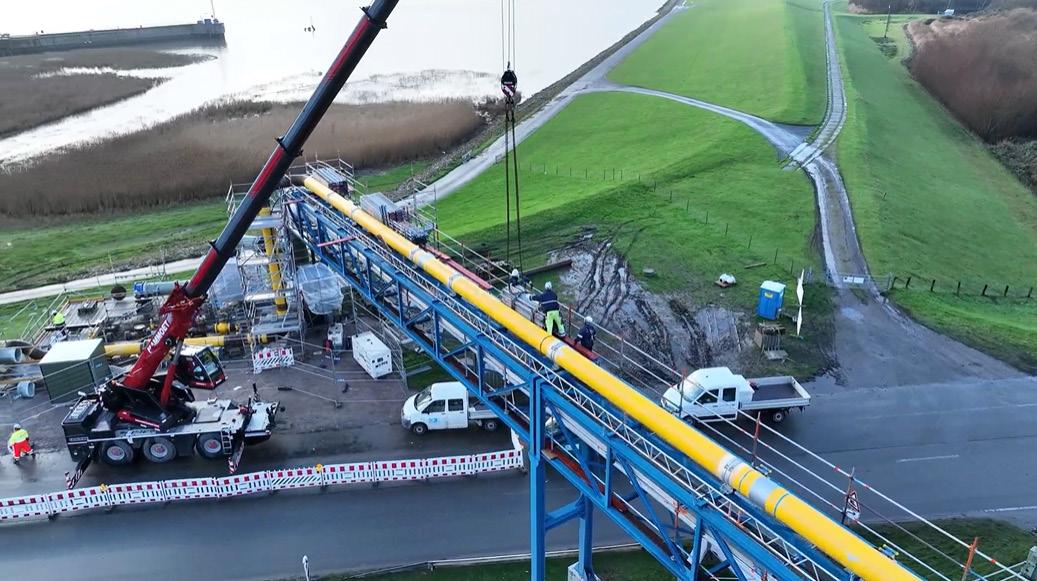
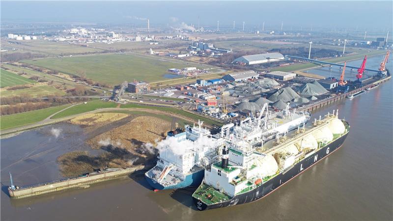
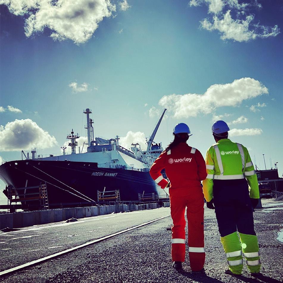
searched for second-hand equipment. With the help of all parties involved, it secured a 30 kV transformer and some suitable 10 kV switchgear.
The Worley team received construction permits by mid-October, which allowed construction activities to commence just as temperatures were plummeting at the start of winter.
The approval authorities worked rapidly to avoid any preventable delays. While the construction teams mobilised quickly, they soon discovered more underground cables and pipes. This required some hand digging to keep the project moving, as freezing weather took hold onsite.
Worley handled all the logistics to expedite the delivery of equipment and materials. This included arranging an Antonov aircraft to bring in a control room from Türkiye. Similarly, it used a helicopter to install a new vent stack at the site – an operation that took only 11 minutes from lifting to bolting down.
The FSRU, the Höegh Gannet, arrived at Brunsbüttel Port on 20 January 2023. With the FSRU at berth, the Worley team quickly completed final hook-up activities and pre-commissioning checks.
The first LNG cargo was delivered to the FSRU from ADNOC on 15 February 2023 and the first gas was successfully fed into the gas distribution system in the middle of March 2023. The team met the deadline to have the FSRU in operation and natural gas being delivered into the grid by the second half of winter.
Overall, the Worley team delivered first gas from the LNG terminal into the grid system in less than nine months. Such a project would usually have taken around two years.
FSRU projects such as this one are not usually as technically complex as those involving energy facilities such as liquefaction plants, refineries, or offshore platforms. However, the Brunsbüttel project broke new ground by using agile procurement, work sequencing, and collaboration to achieve a successful result in a short timeframe. Worley and the German government also took an innovative approach to managing risk, given equipment had to be bought before engineering was finalised.
While the project relates to the supply of hydrocarbons for short-term energy security, the learnings it offers are applicable to other initiatives. It shows that when the industry collaborates and embraces new ways to deliver complex energy infrastructure, the most ambitious projects can quickly become real.
Since the completion of Phase 1, Worley is now supporting the state-owned operator of the terminal, Deutsche Energy Terminal GmbH, by undertaking the engineering, procurement, construction and commissioning of the next phase of the project. This phase follows a more conventional schedule. Phase 2 involves the new permanent jetty and berth, topsides facilities with new high pressure gas marine loading arms and new water supply to connect with the FSRU. Once the infrastructure is completed, the FSRU will be relocated to this new berth to continue operations with the benefit of increased gas flowrates into the grid system.
Francesca Serra and Filippo Perricone, HIGAS, Italy, delves into boil-off gas management at small scale LNG terminals.

he HIGAS LNG storage terminal, located in the port of Oristano, Sardinia, is the first small scale coastal LNG storage facility in the Mediterranean. Operational since 2021, the terminal was designed to receive LNG from small and medium-sized LNG carriers.
It has a net storage capacity of 9000 m 3 , divided among six horizontal tanks, each with a capacity of 1500 m 3 . Unlike the large vertical tanks used in large scale terminals that operate at atmospheric pressure, the terminal’s tanks are specially designed to function at pressures between 1 – 1.5 barA, with a maximum limit of 4 barA. This configuration provides greater flexibility in managing stored LNG,
enabling HIGAS to effectively respond to demand fluctuations or emergency situations, with the potential to handle bio-LNG in the future.
The use of smaller, distributed tanks also allows for scheduled maintenance on individual tanks without disrupting the plant’s overall operation, ensuring both operational continuity and safety.
The terminal essentially supports four output modes. The primary output is the distribution of LNG by truck to local customers who are not served by a pipeline network due to Sardinia’s geographic constraints; this distribution is vital to meet the energy needs of around 100 municipalities and various industries on the island, particularly in remote areas where access to supply is challenging.
The second output is energy self-production through two gas generators. The third involves send the natural gas into a local pipeline currently under construction, which will supply natural gas to the city and industrial area of Oristano. Lastly, the terminal is designed for LNG bunkering operations at the quay, offering refuelling services for vessels in a strategic Mediterranean area.
The management of boil-off gas (BOG) is one of the primary challenges for LNG storage facilities, especially for small scale terminals like HIGAS. Different to large scale plants, where more resources and technical solutions are available, small scale terminals must address operational and sustainability challenges with a stronger focus on energy efficiency and operational flexibility. Managing BOG becomes a crucial aspect to maintain system stability to ensure safety.
This article will explore how the terminal addresses this challenge by detailing the roles of vaporisers, the subcooler, and its vapour buffer tank (VBT), as well as how its processes are optimised.
BOG develops in cryogenic tanks due to the evaporation of LNG as a natural process since external heat penetrates through the insulation barriers. This fact is inevitable since no insulation system is entirely perfect. However, managing BOG is essential to prevent the pressure inside the tank from rising to dangerous levels, which could result in the opening of safety valves and the release of gas to the flare. In large scale plants, the common solution for handling BOG involves using complex reliquefaction systems, which condense the evaporated gas back into LNG. However, HIGAS terminal adopted a different and more sustainable approach, suited to the size and operational needs.
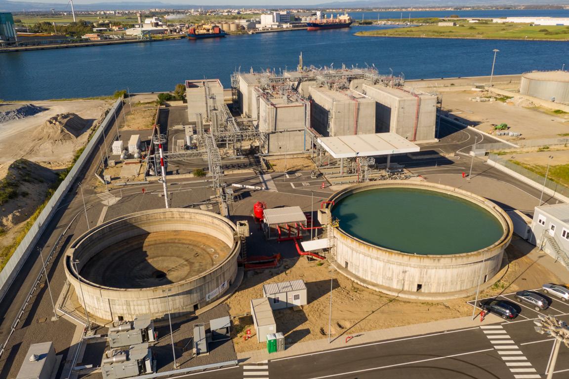
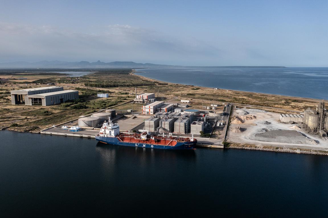
One of the most significant features of the BOG management system is the VBT. The VBT is a tank designed to temporarily store evaporated gas from the main tanks, reducing the internal pressure of the tanks and thus preventing the opening of safety valves. Thanks to the VBT, the BOG can be managed more flexibly, keeping the gas ready to be used by external utilities.
The VBT’s capacity is sufficient to handle the BOG generated during normal operational cycles, ensuring that the gas can be used as fuel for the gas generator (which is installed for self-power generation), or sent to a nearby distribution network.
In fact, one of the most innovative aspects of the terminal’s BOG management is focused on providing this gas to power, industrial, and residential users located near the terminal. Thanks to the strategic location of the Oristano port, where there are industries potentially interested in using natural gas, this significantly reduces the need for reliquefaction and therefore energy consumption. In this way, the electricity that would normally be used to convert BOG back into LNG is almost entirely saved, making the plant more energy-efficient and reducing operational costs. Additionally, this strategy allows HIGAS to treat BOG as an energy resource, minimising losses.
Another essential element in BOG management are the vaporisers. These devices are used to convert the stored LNG in liquid form
into natural gas, which can then be distributed to final users. At the plant, atmospheric vaporisers are used to harness ambient air heat, warming the LNG and converting it into gas. This process is efficient and does not require additional energy sources like electricity or fuel, thereby reducing operational costs and minimising energy consumption.
At the HIGAS small scale terminal, BOG management goes beyond daily operational activities, extending to long-term planning for storage capacity and gas distribution. Thanks to the plant’s flexibility, it can adapt to changes in market demand by adjusting the volume of stored LNG and modifying the frequency of loading and unloading operations for LNG carriers.
Another important element in BOG management is the subcooler. The subcooler is a device used to further cool the LNG, thereby reducing the rate of evaporation inside the tanks and condensing part of the gas phase above the LNG. This occurs as the subcooled liquid is sprayed through a cool down ring onto the contained vapour.
During periods when gas demand is reduced and LNG remains in the tanks for longer periods, the subcooler becomes an essential tool to ensure system stability and reduce the need for corrective actions.
The combination of these technologies allows the terminal to efficiently manage BOG, reducing the environmental impact as a result. Furthermore, this approach to BOG management helps the terminal reduce its dependency on external energy sources and optimise the use of available resources, making the terminal an example of sustainability in the LNG sector.
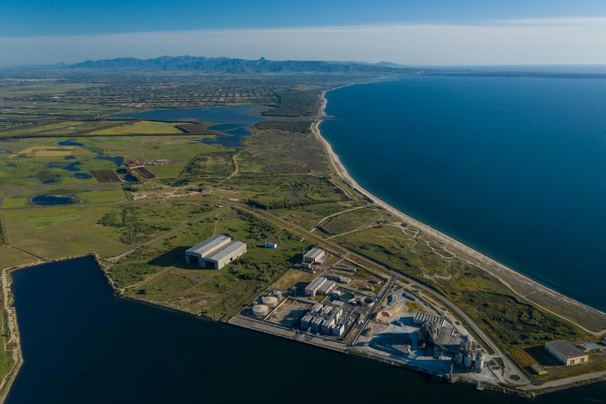
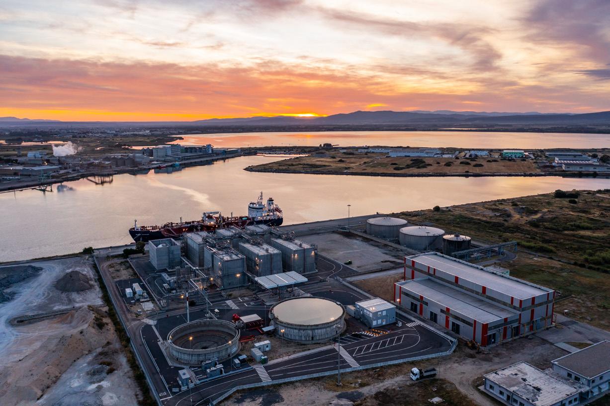
This capacity allows HIGAS to operate nimbly, adapting operations based on market demand and ensuring a constant and reliable supply of natural gas to users. On top of that, LNG carrier and truck loading capabilities allows for a timely response to changes in demand, minimising downtime, and optimising resource management.
An essential aspect of the BOG management strategy concerns safety. Effectively managing BOG requires careful planning and constant monitoring of operational parameters, such as the temperature and pressure inside the tanks. These parameters are critical to ensure that the system operates within safe limits and to prevent any potential hazards associated with the handling of LNG.
To enhance safety, the terminal utilises a combination of advanced technologies and robust operational protocols. Safety systems include valves that are designed to automatically vent exceeding pressure, thus preventing tank overpressure situations that could lead to undesired gas releases.
In addition to mechanical safety systems, the terminal has an advanced automatic control system that continuously monitors tank conditions in real time. These systems utilise hundreds of sensors to detect any deviations from the established safety parameters. Should any irregularities arise, the control systems trigger alarms and initiate pre-programmed safety protocols, which may include isolating affected areas and initiating emergency shut-down procedures if necessary.
By integrating these safety measures into the BOG management strategy, HIGAS is committed to protecting both personnel and the surrounding environment. The proactive approach to safety is focused not only on minimising the risk of accidental gas losses, but also enhances operational efficiency, allowing the BOG to be managed effectively while maintaining the highest standards of safety.
At the HIGAS Terminal in Oristano, the issue of LNG ageing is virtually non-existent due to the dynamic and frequent management of gas. Unlike other facilities that store LNG for extended periods, this terminal
employs an operational strategy based on regular and optimised loading and unloading cycles, including the use of vaporisers and subcoolers. These devices play a critical role in maintaining the quality of LNG over time – the vaporisers ensure the efficient conversion of LNG to natural gas for distribution (avoiding natural distillation and preventing an ageing effect), while the subcooler condensates the evaporated lighter components, maintaining the optimal composition of the stored LNG. Preventing the loss of lighter fractions, the system keeps the boil-off rate below 0.1%, ensuring that LNG is not stored long enough to undergo significant changes in its composition. Additionally, by utilising BOG as an energy source for internal systems and distributing gas to nearby consumers, the terminal minimises its reliance on external energy. This strategy contributes to operational efficiency and sustainability, making the HIGAS terminal an example of modern LNG storage and management. The combination of advanced technology, attention to sustainability, and operational flexibility ensures optimal LNG quality and a reliable energy supply for Sardinia’s market.
Attention to sustainability and energy efficiency further contributes to ensuring the quality of stored LNG. The terminal is designed to minimise the use of external
energy by utilising BOG as a fuel source for its internal systems and for distributing gas to nearby consumers. This approach not only improves operational efficiency, but also ensures that stored LNG is managed optimally, reducing losses and preserving its properties.
In conclusion, BOG management at HIGAS’ small scale terminal in Oristano represents an optimised balance between operational efficiency, energy sustainability, and safety. By utilising all available technologies such as vaporisers, subcooler, and compression systems, the terminal can manage BOG optimally, minimising waste and maximising operational efficiency.
The ability to adapt to market needs and treat BOG as an energy resource enables the terminal to operate sustainably and competitively, providing reliable and safe service to industrial and residential users. The HIGAS terminal is effectively able to manage the challenges associated with LNG ageing thanks to advanced technologies, dynamic operational strategies, and a constant focus on product quality. This integrated approach ensures that stored LNG retains its properties, allowing the terminal to operate sustainably, reliably, and competitively.