April 2024

Maximize asset value through specialty chemical experience and expertise.


03 Comment
05 World news
08
Evaluating risks and diversifying economies
Gord Cope, Contributing Editor, discusses the state of the refining and petrochemical sector in the MENA region and reveals how countries are looking to tap into the green fuels sector.
14 2024: the year the world wakes up to methane emissions?
Mark Naples, Umicore Coating Services, considers how the threat of methane emissions can finally be conquered in the oil and gas industry.
19 SAF: viability, scale and economic advantage
Paul Ticehurst, Johnson Matthey, UK, discusses the importance of sustainable aviation fuel (SAF) for decarbonisation, the technology that supports large-scale production of this fuel, and the economic benefits it could present.
23 A new value for plastic waste
Antonio Batistini, Enrico De Dominicis, Massimo Di Amato, Barbara Morico, Emma Palo, and Paola Sclafani, MAIRE, Italy, explore how depolymerisation technology can support the creation of new circular value chains in the plastics sector.
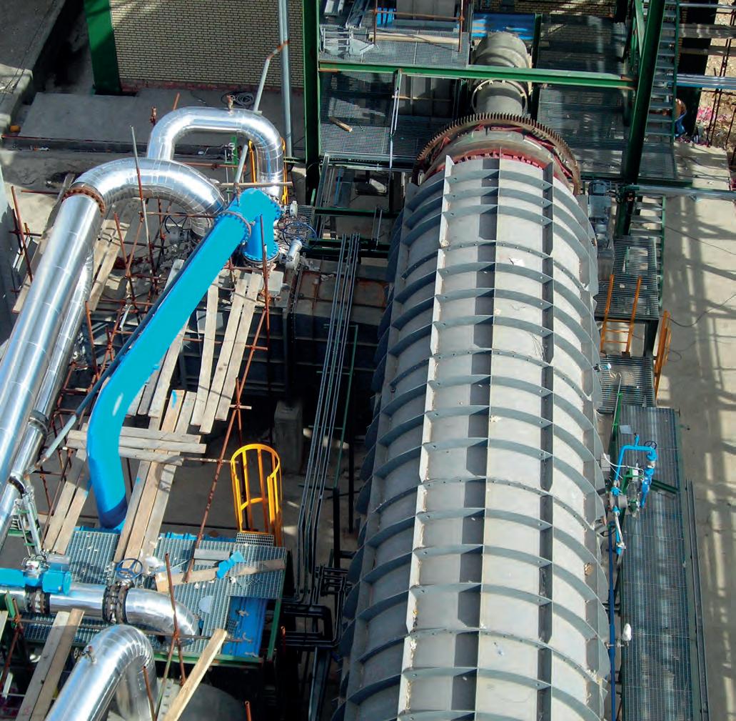
29 A new circular plastic ecosystem
Kae S. Wong, Fabrice Cuoq, Giri Anupam, Omid Emamjomeh and Christoph J. Dittrich, SABIC Global Technologies B.V., alongside Rasha H. Daadoush and Vishvedeep Bhatt, Aramco, highlight how adsorption is an effective way to stabilise and remove chlorides in plastic derived oil (PDO) to protect downstream assets.


35 Guidelines for optimising C5/C6 isomerisation units
Fatemah Jameel Fraidoun, Kuwait National Petroleum Company (KNPC), presents a case study in which the Mina Al Ahmadi refinery optimised its isomerisation unit in order to reduce the isomerate Reid vapour pressure and maintain high research octane number.
39 Diagnostic technologies for process optimisation
Jaspreet Nijjar, Tracerco, UK, explores the benefits offered by specialist scanning and radiotracer technologies in optimising processes.
45 Smarter, safer working
Mark Breese, Yokogawa RAP, considers the importance of digital control of work (CoW) systems in promoting more intelligent operations and an improved safety culture in the downstream industry.
49 Simplifying safety in a complex world
Eric Sallee, OsecoElfab, explores how advances in rupture disc technology can help refineries and chemical processing facilities minimise overpressure risks and reduce emissions.
53 Surface engineering process and applications
Sunil Musali, MOGAS Surface Engineering, USA, discusses the use cases for thermal spraying and laser cladding in surface engineering.
56 Navigating cybersecurity challenges
Paul Evans, Nozomi Networks, discusses the challenges faced by the downstream oil and gas industry as it embraces digitisation.
59
A specialised approach to assessing cybersecurity risks
Mary Sebastin and Saltanat Mashirova, Honeywell OT Cybersecurity, explain why cyber-physical risk assessments are essential in protecting petrochemical and oil and gas facilities from cybersecurity threats.
63 Cyber-enemies at the gate
Avoiding the cybersecurity problem is no longer a viable strategy, but putting protections in place is more straightforward than it seems. Alexandre Peixoto, Emerson, explains.
67 Sulfur review
Hydrocarbon Engineering presents a selection of the most advanced sulfur technolgies and services that are currently available to the downstream sector.
Halliburton Multi-Chem provides industrial water and process treatment solutions to refineries and petrochemical plants. Through onsite technical service and engineering support, the company helps customers with business goals, including improving reliability, increasing throughput, and enhancing the efficiency and flexibility of operating units. Halliburton Multi-Chem’s aim is to protect assets and maximise value.

CONTENTS April 2024 Volume 29 Number 4 ISSN 1468-9340 CBP019982 Hydrocarbon Engineering Like Join Hydrocarbon Engineering @HydrocarbonEng Follow CONVERSATION JOIN THE 2024 Member of ABC Audit Bureau of Circulations Copyright© Palladian Publications Ltd 2024. All rights reserved. No part of this publication may be reproduced, stored in a retrieval system, or transmitted in any form or by any means, electronic, mechanical, photocopying, recording or otherwise, without the prior permission of the copyright owner. All views expressed in this journal are those of the respective contributors and are not necessarily the opinions of the publisher, neither do the publishers endorse any of the claims made in the articles or the advertisements. Printed in the UK. THIS MONTH'S FRONT COVER

Cut your CO2 emissions in half with ET Black™
Carbon Black Technology
ET Black™ is a state-ofthe-art technology that complies with the most stringent environmental regulations now and in the future.
Plus, the flexibility to produce all ASTM grades, and specialty grades, in a single plant. ET Black™, the technology of reference for producing carbon black obtained by thermal decomposition of highly aromatic oils.
Find out more at: www.igoforETBlack.com


CONTACT INFO
MANAGING EDITOR James Little james.little@palladianpublications.com
SENIOR EDITOR Callum O'Reilly callum.oreilly@palladianpublications.com
EDITORIAL ASSISTANT Poppy Clements poppy.clements@palladianpublications.com
SALES DIRECTOR Rod Hardy rod.hardy@palladianpublications.com
SALES MANAGER Chris Atkin chris.atkin@palladianpublications.com
SALES EXECUTIVE Sophie Birss sophie.birss@palladianpublications.com
PRODUCTION MANAGER Kyla Waller kyla.waller@palladianpublications.com
EVENTS MANAGER Louise Cameron louise.cameron@palladianpublications.com
DIGITAL EVENTS COORDINATOR Merili Jurivete merili.jurivete@palladianpublications.com
DIGITAL CONTENT ASSISTANT Kristian Ilasko kristian.ilasko@palladianpublications.com
DIGITAL ADMINISTRATOR Nicole Harman-Smith nicole.harman-smith@palladianpublications.com
ADMIN MANAGER Laura White laura.white@palladianpublications.com
CONTRIBUTING EDITORS Nancy Yamaguchi Gordon Cope

CALLUM O'REILLY SENIOR EDITOR
Back in February, the landing of a first commercial spacecraft on the Moon sparked a wave of excitement about a new era of private lunar exploration. The successful touchdown of US-based Intuitive Machines’ unmanned Odysseus lander marked the first time that a US craft has landed on the Moon since 1972, and it is hoped that it will change the face of planetary exploration. It could help to fund future state missions, and eventually aid plans to set up a permanent human base on the Moon (and beyond).
While the Odysseus lander grabbed most of the headlines, another vitally important space mission took place shortly after. On 4 March, a groundbreaking satellite designed to help protect the Earth’s climate successfully launched from Vandenberg Air Force Base in California, US. MethaneSAT – developed by a subsidiary of the Environmental Defense Fund (EDF) and partnered by the likes of Google, SpaceX, and the New Zealand Space Agency – will find and measure methane emissions over wide areas. The satellite, which will focus first on oil and gas operations, processes observed spectrographic data to calculate quantitative emission rates, revealing how much methane is emitted. “MethaneSAT’s superpower is the ability to precisely measure methane levels with high resolution over wide areas, including smaller, diffuse sources that account for most emissions in many regions”, said Steven Hamburg, EDF Chief Scientist and MethaneSAT Project Leader. “Knowing how much methane is coming from where and how the rates are changing is essential.”
According to the project backers, the unique capabilities of MethaneSAT will create unprecedented transparency. Interactive emissions data will be available free of charge, enabling anyone to see and compare emissions results by company, country or production basin. Ultimately, this will enable operators to find and fix problems faster.
As outlined in an excellent article from Umicore Coating Services that features in this issue of Hydrocarbon Engineering, the world seems to be finally waking up to the substantial threat posed by this invisible gas, and finding the solutions to conquer it. A number of new announcements to reduce methane emissions were made at the COP28 summit in Dubai, and over 150 countries have now signed up to the Global Methane Pledge to reduce methane emissions by at least 30% below 2020 levels by 2030.
What’s more, MethaneSAT is just one of the tools that is now available to help oil and gas producers to collect data on their emissions. Indeed, the team behind MethaneSAT point to a ‘complementary ecosystem’ of methane satellites for addressing emissions globally, including a satellite developed by the European Space Agency. A new global satellite methane detection and notification system (known as the Methane Alert and Response System, or MARS for short) is also extremely promising for the industry. As Mark Naples, Managing Director of Umicore Coating Services, explains in his exclusive article starting on p. 14 of this issue: “Energy suppliers could soon have access to a suite of tools and funding to reduce gaps in their understanding of where emissions are occurring, enabling them to act as never before against this invisible threat.”
SUBSCRIPTION RATES Annual subscription £110 UK including postage /£125 overseas (postage airmail). Two year discounted rate £176 UK including postage/£200 overseas (postage airmail). SUBSCRIPTION CLAIMS Claims for non receipt of issues must be made within 3 months of publication of the issue or they will not be honoured without charge. APPLICABLE ONLY TO USA & CANADA Hydrocarbon Engineering (ISSN No: 1468-9340, USPS No: 020-998) is published monthly by Palladian Publications Ltd GBR and distributed in the USA by Asendia USA, 701C Ashland Avenue, Folcroft, PA 19032. Periodicals postage paid at Philadelphia, PA & additional mailing offices. POSTMASTER: send address changes to HYDROCARBON ENGINEERING, 701C Ashland Ave, Folcroft PA 19032.
South Street, Farnham, Surrey GU9 7QU, UK
+44 (0) 1252 718 999 COM MENT
15
Tel:


WORLD NEWS
Global | Methane emissions from the energy sector remained near record high in 2023
Methane emissions from the energy sector remained near a record high in 2023, according to new analysis from the International Energy Agency (IEA).
The IEA’s latest update of its ‘Global Methane Tracker’ is the first comprehensive assessment of global methane emissions since the COP28 climate summit concluded in December 2023. The new analysis finds that the production and use of fossil fuels resulted in close to 120 million t of methane emissions in
2023, a small rise compared with 2022.
According to the report, the top 10 emitting countries were responsible for around 80 million t of methane emissions from fossil fuels in 2023.
However, the IEA notes that substantial policies and regulations announced in recent months, as well as fresh pledges stemming from the COP28 climate summit, have the potential to put methane emissions into decline soon.
Canada | Pembina awards contract for RFS IV expansion
Pembina Infrastructure and Logistics LP has awarded Worley a contract for RFS IV, the expansion of Pembina’s existing Redwater propane-plus fractionation and storage complex in Alberta, Canada.
Under the contract, Worley will provide fabrication and module assembly from its Blackfalds and Edmonton modularisation yards.
The company will also provide field construction services at the Redwater complex.
Worley categorises this contract as transitional work.
1 RFS IV is expected to increase the fractionation capacity by 55 000 bpd (8744 m3), enabling the complex to meet increased demand in the region.
China | Clariant and Lummus awarded catalyst technology contract for new isobutane dehydrogenation plant
Clariant and its process partner
Lummus Technology have been selected by Huizhou Boeko Materials Co. Ltd to provide their CATOFIN catalyst and process technology for the dehydrogenation of isobutane at the new plant in Huizhou City, China. The process technology is exclusively licensed by Lummus Technology, while the tailor-made catalyst is supplied by Clariant.
This is the first time that Huizhou Boeko will license the CATOFIN technology at one of its sites.
The scope of this award includes the technology license and basic engineering. Once complete, the plant will produce 550 000 tpy of net isobutylene, which will serve as feedstock for the downstream production of methyl tertiary butyl ether (MTBE).
USA | TotalEnergies acquires Talos Low Carbon Solutions
TotalEnergies has signed an agreement to acquire 100% of Talos Low Carbon Solutions (TLCS), a US company focused on carbon capture and storage.
After completion of the transaction, TotalEnergies will own a 25% share in the Bayou Bend project, alongside Chevron (50%, operator) and Equinor (25%).
The Bayou Bend project is a major CO2 storage project located along the Texas Gulf Coast, close to the company’s assets in the region. TotalEnergies will also own a 65% operated interest in the
Harvest Bend (Louisiana) project and a 50% interest in the Coastal Bend (Texas) project. With Coastal Bend and Harvest Bend being located farther away from the company’s other existing assets, TotalEnergies’ intention is to divest its interest in these two projects after closing.
The Bayou Bend project is a carbon transportation and storage solution for industrial emitters located in the Houston Ship Channel and Beaumont – Port Arthur region, one of the largest industrial corridors in the US. Comprising licenses dedicated to CO2 storage,
offshore and onshore, covering approximately 600 km2, it could enable the storage of several hundred million tons of CO2
Patrick Pouyanné, Chairman and CEO of TotalEnergies, said: “TotalEnergies is pleased to enter the Bayou Bend project through the acquisition of Talos Low Carbon Solutions. Ideally located close to our Port Arthur refinery and our petrochemicals assets in La Porte, this project will be instrumental for the reduction of direct emissions from our US operations.”
April 2024 HYDROCARBON ENGINEERING 5

WORLD NEWS
DIARY DATES
29 April - 03 May 2024
RefComm Galveston, Texas, USA www.events.crugroup.com/refcomm
06 - 08 May 2024
ILTA Conference & Trade Show Houston, Texas, USA ilta2024.ilta.org
14 - 16 May 2024
Asia Turbomachinery & Pump Symposium Kuala Lumpur, Malaysia atps.tamu.edu
10 - 14 June 2024
ACHEMA Frankfurt, Germany www.achema.de/en
11 - 13 June 2024
Global Energy Show Canada Calgary, Alberta, Canada www.globalenergyshow.com
20 - 22 August 2024
Turbomachinery & Pump Symposia Houston, Texas, USA tps.tamu.edu
17 - 20 September 2024
Gastech Houston, Texas, USA www.gastechevent.com
22 - 25 September 2024
GPA Midstream Convention San Antonio, Texas, USA www.gpamidstreamconvention.org
15 - 17 October 2024
AFPM Summit New Orleans, Louisiana,, USA summit.afpm.org
04 - 06 November 2024
Sulphur + Sulphuric Acid 2024 Barcelona, Spain www.events.crugroup.com/sulphur
11 - 14 November 2024
ERTC
Lisbon, Portugal
www.worldrefiningassociation.com/event-events/ ertc
UAE | Technip Energies, JGC and NPCC receive LNTP for Ruwais LNG Project
Technip Energies, leader of a joint venture (TJN RUWAIS JV) with JGC and NPCC, has received a Limited Notice To Proceed (LNTP) from ADNOC to commence early engineering, procurement and construction (EPC) activities at the Ruwais low-carbon LNG project, located in Al Ruwais Industrial City, Abu Dhabi, UAE.
The project will consist of two natural gas liquefaction trains with a total LNG production capacity of 9.6 million tpy. The plant will use
electric-driven motors instead of conventional gas turbines and will be powered by nuclear energy.
The plant is set to be the first LNG export facility in the Middle East and North Africa (MENA) region to run on clean power, making it one of the lowest-carbon intensity LNG plants in the world.
The project will significantly enhance ADNOC’s LNG production capacity, aligning with global natural gas demand and the shift towards decarbonisation.
Canada | Air Products awards module fabrication agreement to Worley
Air Products Canada Ltd has awarded Worley an agreement to provide procurement, fabrication and modularisation services for its Net-Zero Hydrogen Energy Complex, located in Edmonton, Alberta, Canada.
Once operational, Air Products says that the net-zero complex will produce clean hydrogen and capture and permanently sequester carbon dioxide (CO2) emissions.
It is expected to position Alberta as the centre of western Canada’s hydrogen economy. Under the agreement, Worley’s Edmonton modularisation yard will fabricate and assemble process and pipe rack modules, implementing automated pipe-cutting techniques and robotic welding. Worley’s Edmonton modularisation yard is located adjacent to Air Products’ Net-Zero Hydrogen Energy Complex.
USA | EIA expects low natural gas prices
The US Energy Information Administration (EIA) expects the benchmark Henry Hub spot price to average about US$2.25/million Btu in 2024, a 10% decrease from 2023 and a 65% decrease from 2022.
In its March ‘Short-Term Energy Outlook’ (STEO), EIA forecasts that US natural gas inventories will be more than 30% higher than average at the end of the winter season following relatively low winter demand.
According to EIA’s forecast, low natural gas prices will slightly decrease domestic natural gas production in
2024 compared with record production in 2023.
EIA expects US crude oil production to continue growing in 2024 and 2025, with both years exceeding the production record set in 2023. Growth in US crude oil production should help offset the effects of continued voluntary OPEC+ oil production cuts announced recently, but EIA still expects a tight balance of global oil production and demand, which EIA forecasts will lead to higher Brent crude oil prices in 2024 than expected at the start of the year.
April 2024 HYDROCARBON ENGINEERING 6

Revamp to thrive in the new reality
Ever-changing market conditions, global economic challenges, and the shared journey of the energy transition all mean it is crucial to evaluate easy-to-implement and costeffective improvement opportunities. At Shell Catalysts & Technologies, our solutions open new possibilities for smarter investments while preserving cash through revamping, reconfiguring, or optimising your existing assets. Our experts co-create tailored solutions while keeping your margins in mind – ensuring the investments you make right now can help you maintain your competitive advantage into the future.
Learn more at catalysts.shell.com/revamps.

Gord Cope, Contributing Editor, discusses the state of the refining and petrochemical sector in the MENA region and reveals how countries are looking to tap into the green fuels sector.
8 April 2024 HYDROCARBON ENGINEERING
Turmoil abounds in the Middle East and North Africa. In addition to the Hamas-Israel war, Iran’s proxies are busy stirring up trouble in Yemen and Lebanon, while various domestic conflicts grip countries in Egypt, Algeria, Iraq and other jurisdictions. Yet, the region is ripe with fossil fuels and green energy potential that is greatly sought after by consuming nations in Europe and Asia.
Egypt produces approximately 680 000 bpd of crude, most of which is slated to be converted to fuels in its dozen domestic refineries. Several billion dollars are being spent upgrading various complexes, including a US$2 billion project to add a hydrocracker to Egyptian General Petroleum Corp.’s Assiut refinery. At the southern end of the Suez Canal, Red Sea Refining and Petrochemicals is building the Tahir refinery and petrochemicals plant in the port of Ain Sokhana. When completed later in the decade, it will have the capacities of 1.5 million tpy of ethylene and 600 000 tpy of propylene.
In May 2023, Suez Methanol Derivatives Co. (SMD) signed an agreement with Methanex Egypt to supply feedstock for its specialty-chemicals complex in the port of Damietta. The US$120 million complex is the first of its kind in Egypt, and will produce 140 000 tpy of urea formaldehyde concentrate, naphthalene formaldehyde and specialty resins for domestic and export markets. Construction is currently underway, with first product deliveries expected in October 2024.
Algeria’s oil and gas sector is in an enviable position. It ships approximately 45 billion m3 of natural gas annually through Mediterranean subsea pipelines and LNG tankers to Europe.

In addition, it produces 1.3 million bpd of light, sweet crude, the majority of which is exported.
In an effort to satisfy growing domestic demand, state-owned Sonatrach has launched an ambitious plan to expand the 670 000 bpd capacity of its domestic refineries. The Hassi Messaoud refinery, adjacent to its largest oilfield, is being enlarged from 23 000 bpd to 110 000 bpd capacity. It also plans to eventually expand and upgrade its Bishkra, Tiaret and Skikda refineries to similar capacities. But recent reports note that Sonatrach is at loggerheads with Samsung and Técnicas Reunidas (Hassi Messaoud’s EPC contractors) over costs associated with the US$3.7 billion expansion; negotiating a financial resolution may delay final investment decisions (FIDs) on the three latter refinery projects.
In December 2022, Saudi Aramco and TotalEnergies announced a joint plan to build a US$11 billion petrochemical facility in the Saudi port of Jubail adjacent to the existing SATORP refinery. The new complex will contain one of the largest mixed-load steam crackers in the Middle East, with a capacity to produce approximately 1.6 million tpy of ethylene and other gases. The feedstock is expected to underpin a further US$4 billion investment in related industrial sectors, including the manufacture of carbon fibres, lubricants, detergents, automotive parts and food additives. In June 2023, it was announced that Hyundai Engineering would build the mixed-feed crackers, Maire Tecnimont would construct two polyethylene units, and Sinopec Engineering would fabricate the tank farm. Tentative completion is set for 2027.
April 2024 9 HYDROCARBON ENGINEERING
Qatar continues to pursue its goal to be the world’s leading LNG exporter. In October 2023, it broke ground on the world’s largest LNG project, the North Field Expansion (NPE). When completed later in the decade, it will boost the country’s current capacity of 77 million tpy by a further 48 million tpy. That same month, it signed long-term deals with Shell to supply up to 3.5 million tpy of LNG for deliveries to the Netherlands, starting in 2026 when the first phase of its major expansion comes online. The news comes on the heels of a similar announcement between QatarEnergy and TotalEnergies to supply up to 3.5 million tpy to France. All deals are set at 27 years in duration.
In late 2023, QatarEnergy and Chevron Phillips Chemical Co. secured US$4.4 billion in financing for a US$6 billion polymers facility in Qatar’s Ras Laffan Industrial City. The project will include the largest ethane cracker in the Middle East, with a capacity of 2.1 million tpy, as well as two, high-density polyethylene units with a total capacity of 1.7 million tpy. When completed in 2026, most of the output will be exported for use in durable goods such as gas and water distribution pipes.
Borouge is the UAE’s major petrochemical complex, located in the downstream hub of Ruwais. The plant, which is jointly owned by ADNOC and Austrian partner Borealis, produces 5 million tpy of poly-olefin compounds, which are used in a wide variety of industrial applications in Europe and Asia. The US$6.2 billion Borouge-4 expansion project is currently under construction, and will add 1.5 million tpy of capacity.
Kuwait holds approximately 100 billion bbl of crude reserves, and currently produces 2.7 million bpd. The state has plans to increase production to 3.25 million bpd by 2027, and to 4 million bpd by 2035. Kuwait Integrated Petroleum Industries Co. (KIPIC) is also commissioning the latest expansion of its Al Zour refinery complex in the Persian Gulf, boosting domestic refining capacity to 1.6 million bpd. A major new olefins plant is being built nearby. When completed in 2025, it will produce 2 million tpy of olefins and 1.44 million tpy of polymers.
Iraq currently produces 4.3 million bpd from 140 billion bbl of crude reserves. In January 2024, The Iraqi Ministry for Energy Affairs and Oil announced plans to increase oil production to 6 million bpd by the end of the decade. In addition, the country would like to reduce its dependency on imported refined products by increasing refining capacity. It currently has 16 refineries producing approximately 1 million bpd of fuel and related products. The government seeks to add a total of 320 000 bpd of new capacity, and has issued tenders to build the 150 000 bpd Nasiriyah in the Southern Dhi Qar Governorate, the 100 000 bpd Al-Kut refinery in eastern Iraq, and the 70 000 bpd Samawah refinery in southern Iraq. In addition, Iraq announced plans to finally initiate the Nibras petrochemical complex in Basra to leverage substantial gas reserves in the region. The JV between Shell and the federal government is expected to produce 1.8 million tpy of petrochemical products when it comes on-stream at the end of the decade.
Iran, with 156 billion bbl of crude reserves, has a refining capacity of 2.6 million bpd. It also has ambitious plans to expand its refining and petrochemical output; the country has
over 1.4 million bpd of new capacity on the books. The 360 000 bpd Siraf refinery project, designed to split condensate feedstock, is expected to start operations in 2025.
Green energy
MENA countries are hoping to tap into the lucrative, low-carbon fuel sector. While hot, arid conditions are a bane to agriculture, abundant wind and sun allow jurisdictions to use hydrolysis to produce green hydrogen. The energy-dense gas can then be converted into easily-transportable green ammonia for exports to Asia and Europe, where it can be used for utilities and fertilizers, dramatically reducing carbon footprints in these sectors.
Saudi Arabia is building an immense green ammonia plant in the NEOM project, a futuristic greenfield development in the country’s northwest, home to abundant solar and wind resources. The US$5 billion plant would produce up to 650 tpd (240 000 tpy), primarily for export.
As part of the UAE’s plan to supply up to 25% of imported, low-carbon hydrogen in key global markets, its state-owned subsidiary, Fertiglobe, has been shipping demonstration cargoes of blue ammonia to Germany. The ammonia was produced at the company’s Fertil plant in Abu Dhabi’s Ruwais industrial complex; the company is developing a greenfield, 1 million tpy low-carbon ammonia plant at the complex.
In 2022, Egypt announced its National Climate Strategy 2050, which outlined objectives to reduce carbon emissions and produce energy from renewable resources. In May 2023, it signed a US$450 million agreement with Norway’s Statec to build a green methanol plant in Damietta for the purpose of supplying low-carbon fuel for ships. Initial capacity is slated at 40 000 tpy, with the potential to increase to 200 000 tpy. Energy will be supplied by 40 MW of solar power and 120 MW of wind power.
In October 2023, Abu Dhabi’s state-owned ADNOC announced that it had awarded EPC contracts for the Hail and Ghasha Offshore Development. The project is a major milestone for the country’s net zero by 2045 goal; when completed, the two fields will yield 1.5 billion ft3/d, which will be piped ashore where facilities will sequester up to 2 million tpy of CO2 while producing low-carbon hydrogen. The National Petroleum Construction and Saipem S.p.A will build the artificial islands and subsea pipelines, and Tecnimont S.p,A. will construct the onshore CO² and sulfur recovery modules. ADNOC intends to have up to 10 million tpy of CO2 sequestration in place by 2030.
Oman has announced plans to produce 1 million tpy of renewable hydrogen by 2030, 3.75 million tpy by 2040 and 8.5 million tpy by 2050, with the intention of exporting the majority in various forms of ammonia. In addition to building extensive solar farms, the country, which exports 200 000 tpy of grey ammonia products, would need to spend tens of billions in order to massively expand its terminals capacities.
Morocco is a major producer of phosphate fertilizer, which is sold both in its pure form and mixed with other fertilizers. When ammonia prices spiked in the immediate aftermath of the Ukraine war, state-owned fertilizer producer OCP found itself spending almost US$2 billion on imports to meet its mixed-fertilizer contracts. OCP now plans to invest US$7 billion on constructing a green ammonia plant in the coastal town of
April 2024 HYDROCARBON ENGINEERING 10
Tarfaya. The facility is expected to produce 1 million tpy when it comes on-stream in 2027. While the price of green hydrogen is significantly higher, OCP views the investment as a hedge to reduce price volatility and increase security of supply.
Problems
The impacts of war continue to reverberate through the Middle East. For the last several years, Egypt, Israel and Jordan have been acting in concert to build a regional energy network to commercialise the gas discoveries in their respective offshore waters. Egypt, which acts as a regional energy hub for oil, gas, LNG and refined products, has been receiving approximately 800 million ft3/d of gas from Israel’s various fields, including Tamar. When the Hamas-Israel war began, Israel ordered the Tamar field to be shut-in, and to reroute production from the Leviathan field to Jordan. While the move proved temporary, Egypt suffered daily blackouts and disruptions to its LNG exports, and highlighted the fragility of regional energy markets. Houthi attacks on vessels transiting the Red Sea also constitute a major threat to movement of energy through the Suez Canal. In the short-term, vessels heading to Europe are being re-routed at great expense around the southern tip of Africa.
In the longer term, stakeholders contemplating investment in refining and petrochemical facilities in the region are obliged to reevaluate risk premiums, or to seek out more stable jurisdictions. In late 2023, QatarEnergy and Chevron Phillips Chemical Co. began construction of the US$8.5 billion Golden Triangle Polymers plant in Texas, US. The plant, located approximately 100 miles east of Houston, will feature a 2.08 million tpy ethylene cracker and two high-density polyethylene units with a combined capacity of 2 million tpy. In addition, QatarEnergy has invested US$11 billion in the Golden Pass LNG production facility, also located in Texas.
The potential for the new hydrogen economy carries a tremendous caveat; creating green hydrogen is still far more expensive than the traditional Haber-Bosch process, and advances in electrolysis and solar power, while promising, tantalisingly remain in the ‘next decade’ timeframe. In the meantime, geologists are discovering massive deposits of natural hydrogen in France and around the world, with the potential to drop prices for carbon-free hydrogen precipitously, potentially stranding billions of dollars of hydrolysis assets.
The future
Sanctions against Russian oil exports have had a knock-on effect in MENA; Indian refiners, for instance, once a reliable client, now use discounted Russian shipments for the majority of their feedstock. Jurisdictions without significant refining capacity have experienced economic shock as imported fuel prices have soared. Countries like Saudi Arabia and Qatar, which have the resources to initiate major projects to capture value through petrochemicals, fertilizers and alternate energy fuels, are working to diversify and cushion their economies to some extent. That investment philosophy is likely to continue for the remainder of the decade, creating opportunities for engineering firms, equipment manufacturers and infrastructure builders from Europe, North America and Asia.

Optimized Gas Treating, Inc 212 Cimarron Park Loop, Buda, TX 78610 www.ogtrt.com +1 512 312 9424 Contact us for a free trial SulphurPro® The ULTIMATE in Sulphur Plant Simulation
Based on Chemistry & Engineering Science SulphurPro® The ULTIMATE in Sulphur Plant simulation Optimized Gas Treating, Inc. 212 Cimarron Park Loop, Buda, TX 78610 www.ogtrt.com +1 512 312 9424 Contact us for a free trial
Native Sulphur

© 2024 Halliburton. All Rights Reserved.
Specialty Chemical Solutions
SUPERIOR PROCESS AND WATER TREATMENT SOLUTIONS DRIVEN BY SERVICE EXCELLENCE
Improving reliability, increasing throughput, and enhancing the efficiency and flexibility of operating units are important to you. Halliburton Multi-Chem offers a broad selection of chemistries, equipment, services, and automation to ensure successful results.
Through onsite technical service and engineering support, Multi-Chem collaborates with you to deliver solutions to your challenges. We’re here to help you.
halliburton.com/specialty-chemicals

Many of the countless stories focused on climate change all share a singular villain: carbon.
Carbon – specifically carbon dioxide (CO 2 ) – is central to the environmental conversation. Businesses market themselves to consumers as carbon neutral, technologies like carbon capture are touted as major breakthroughs, while phrases like ‘carbon footprint’ are part of cultural lexicon. This is good news for the fight against climate change, as CO 2 poses a serious long-term risk to the future of the planet.
However, this focus on carbon means that another emissions threat has – until now – slipped largely under the radar: methane. Even the oil and gas industry, a sector forced to continually focus on and invest in reducing harmful emissions, appears to have overlooked the risk posed by methane given the continued prevalence of gas flaring and venting at sites around the world. 1
Thankfully, there are signs that the world is waking up to this invisible threat. And the downstream oil and gas sector has the power to conquer this new threat – but it must change the way it thinks about methane leaks for good.
An invisible threat
Methane emissions represent one of the largest threats facing humankind today. Since the Industrial Revolution, this invisible gas has been responsible for approximately a third of the recorded rise in global temperatures. 2 Without immediate action, emissions from human sources are projected to
14 April 2024 HYDROCARBON ENGINEERING

Mark Naples, Umicore Coating Services, considers how the threat of methane emissions can finally be conquered in the oil and gas industry.
April 2024 15 HYDROCARBON ENGINEERING
increase by up to 13% in the next six years, causing significant and irreparable harm to the planet.
In terms of trapping heat, methane is much more potent than CO 2 and other greenhouse gases – but only for a relatively short time. When first emitted, methane traps roughly 100 times more heat than CO 2 . However, it also starts to break down more quickly, while CO 2 can persist for around a century. Over the course of 20 years, methane traps around 80 times as much heat as CO 2 . Over a century, that number drops to 28 times 3 – still significant, but its impact is blunted enough to allow mitigation to take place.
In other words, while methane emissions are dramatically accelerating the climate towards the 1.5°C warming threshold – beyond which scientists agree the environment would suffer irreparable damage – cutting emissions can reverse this course just as quickly.
Approximately 60% of all methane emissions are caused by human activity, and a third of this is produced by the energy sector through flaring, venting, and leaking infrastructure. 4 Estimates suggest that halving these emissions over the next 30 years will be instrumental in meeting the critical goal of reaching global net zero emissions by 2050.
Urgent action is needed – and the world is starting to wake up to the scale of what is required.
Wake up and smell the methane
In December 2023, representatives from major oil and gas companies around the world committed to action that will cut methane emissions by at least 30% by 2030. The Global Methane Pledge (GMP), made at the COP28 summit in Dubai, UAE, promises a huge leap forward in the fight against climate change. Partners of this agreement have announced that more than US$1 billion of new grant funding will be allocated to support action against methane – more than three times the pre-existing funding levels – and individual action is ongoing to reduce the impact of these harmful emissions further.


Over 150 nations have signed up to the GMP, a commitment to cut human-related methane emissions by 30% by the end of the decade. Included in the pledge is the prospect of financial penalties for businesses that fail to act. The US, for example, plans to introduce a fine of US$900/t of methane emitted this year, which will rise by 67% to US$1500/t in 2026.
Perhaps the most important commitment made at COP28 was the launch of the Data for Methane Action campaign. The Global Methane Hub plans to increase the funding available to governments to take advantage of previously unleveraged data. Alongside the full launch of a new Methane Alert and Response System (MARS), energy suppliers could soon have access to a suite of tools and funding to reduce gaps in their understanding of where emissions are occurring, enabling them to act as never before against this invisible threat.
Firm action at the political level – of the kind demonstrated at COP28 – was sorely needed. But all industries must do their bit to help deliver on these pledges, and few have the same potential to make a difference as the oil and gas industry.
April 2024 HYDROCARBON ENGINEERING 16
Figure 1. Capturing the vast amount of methane wasted each year across the oil and gas industry would mean progress for both the climate crisis and the energy crisis.
Figure 2. Modern sensing technology is highly scalable and available in increasingly small form-factor devices thanks to advances in laser absorption spectroscopy.
Let’s add circularity to heat exchangers
Net Zero. It’s what we all want. And heat exchangers will play a key role in helping us get there. By efficiently transferring energy, they help industry reduce dependency on natural gas and electricity. Not a bad thing in these times of uncertain energy supplies. But that’s just the start.
Now imagine quality HX tubing produced in a sustainable way that lasts longer, resists corrosion and extends the lifecycle of the heat exchanger by years.
Like our super-austenitic Sanicro® 35, which offers a smart alternative to costly nickel alloys. Or other Sanicro or duplex grades, depending on what you need.
Sound interresting? Let’s talk.
alleima.com
A clearer picture
To back these pledges up with action, oil and gas operations need better quality data than is currently available. Limitations in the data on methane emissions have effectively hidden the scale of the problem, preventing optimised action from being taken. For the downstream sector, this is particularly important, as this segment is responsible for 20% of fossil methane emissions on its own. 5
Of course, solving this is easier said than done. The GMP saw several new signatories at COP28, including Kenya, Angola, and Turkmenistan, the latter of which in particular has been highlighted as a methane ‘super-emitter’. More than 5600 super-emitter events have been recorded by UN research since 2019, with little overall reduction observed among many GMP signatories. In certain countries, emissions have even increased. 6 In 2022, two oil and gas fields alone in Turkmenistan were responsible for more global warming than all carbon emissions released by the UK that year. 7
Most oil and gas operators oversee many thousands of miles of pipelines, rendering manual checks impractical at best and expensive, ineffectual time sinks at worst. As a result, leaking pipelines have been widely accepted as a regrettable cost of doing business for decades.
This cost should not be as high as it currently is. In The Guardian’s major investigation of super-emitter events, the largest it found was from a major pipeline near Turkmenistan’s Caspian coast.
This is why the announcement of the MARS at COP28 is so promising for the industry. Recent years have seen rapid progress in satellite tracking and other modelling techniques that have significantly enhanced the capacity of oil and gas producers to collect data on their emissions beyond the upstream. Now, for the first time, it is economically feasible to monitor emissions from pipelines, refineries, and storage facilities thanks to systems like MARS. In collaboration with the Copernicus space programme, it represents the first global system that connects satellite-detected methane emissions with trackable notifications.
In a pilot phase that ran throughout 2023, MARS identified more than 1000 methane plumes from energy production and linked 400 of these to specific facilities. Tools like this are changing the picture of emissions and expanding the available approaches to ensure compliance with global commitments on methane.
This new tool is being supported by a worldwide campaign to encourage more comprehensive data collection. The Data to Methane Action campaign aims to improve the funding available to governments and businesses to enable radical reductions in methane emissions by targeting leaks and policy change. It is supported by satellite monitoring systems and scientific monitoring campaigns, providing transformational tools to help the energy sector scale up its efforts.
There are rewards for engaging in abatement strategies that go far beyond legal compliance, however. The International Energy Agency (IEA)
estimates that around 80% of methane emissions could be avoided at no net cost, because the cost of preventing the leaks will be offset by the market value of the captured gas – with downstream leak detection and repair (LDAR) being the most valuable. As energy prices around the world remain high, every molecule of methane leaked into the atmosphere is worth more than it ever has been.
Action on the ground
While oil and gas businesses wait to benefit from the monitoring systems announced at COP28, they can pre-emptively improve their emissions profiles by taking action on the ground. Thanks to technological advances, businesses today have access to a suite of monitoring solutions for identifying where leaks are occurring, chief among which are high-performance infrared (IR) sensors. These small devices generate beams of IR light that pass through a filter inside a sampling chamber that blocks certain wavelengths.
This means that only the desired wavelengths make it through the filter to a detector, which measures the attenuation of the light it receives to determine the precise concentrations of gases that may be present. Changing filters enable different wavelengths of light to reach the detector, which can, in turn, be used to check for different kinds of gases.
Certain gas analyser instruments incorporate laser diodes mounted on a thermo-electric cooler. This enables the laser’s wavelength to be tuned to match the absorption wavelength of a particular molecule, resulting in enhanced sensitivity and discrimination. These instruments benefit from a lower risk of false alarms, which can plague other common gas detection technologies.
These advanced emission tracking devices mean leak prevention is no longer a hypothetical concept. Supported by the growing groundswell of funding to improve monitoring solutions, today’s energy suppliers have a wealth of options available to track harmful leaks and start to address them.
For too long, the problems caused by invisible gas leaks have remained unseen. Now, the technology is widely available to address those problems, and there is the political will to use it. All that remains is for the oil and gas industry to capitalise – and 2024 could be the year the climate fightback begins.
References
1. https://www.worldbank.org/en/programs/gasflaringreduction/ global-flaring-data
2. https://www.iea.org/reports/global-methane-tracker-2023
3. https://climate.mit.edu/ask-mit/why-do-we-compare-methanecarbon-dioxide-over-100-year-timeframe-are-we-underrating
4. https://energy.ec.europa.eu/topics/oil-gas-and-coal/methaneemissions_en
5. https://www.iea.org/commentaries/the-case-for-regulatingdownstream-methane-emissions-from-oil-and-gas
6. https://www.theguardian.com/environment/2023/dec/02/ us-outlines-measures-to-cut-methane-emissions-by-80-innext-15-years
7. https://www.theguardian.com/world/2023/may/09/mindboggling-methane-emissions-from-turkmenistan-revealed
April 2024 HYDROCARBON ENGINEERING 18
Paul Ticehurst, Johnson Matthey, UK, discusses the importance of sustainable aviation fuel (SAF) for decarbonisation, the technology that supports large-scale production of this fuel, and the economic benefits it could present.

In November 2023, the first ever transatlantic flight in a commercial airliner using drop-in 100% SAF was successfully completed by Virgin Atlantic, representing an enormous step forward in decarbonising air travel. The question now is how can the technology be scaled and what is the wider potential of SAF?
SAF offers a solution to reduce the lifecycle emissions from aviation today, but its production also offers the promise of a huge positive impact on economies. Indeed, in the UK alone, Johnson Matthey and EY have calculated that,
if the UK meets its target of 10% SAF by 2030, not only will this save over 3 million tpy of CO2 from entering the atmosphere (equivalent to taking almost 2 million cars off UK roads), but, if produced locally, it will also add up to £11.9 billion gross value added (GVA) to the UK economy.1
100% SAF in existing aircraft
The key to unlocking the full potential of SAF lies in overcoming the challenges associated with its composition. Traditional jet fuel contains aromatic compounds.
April 2024 19 HYDROCARBON ENGINEERING
These ring-shaped molecules are an important component of the fuel as, among other properties, they enhance lubricity, lower freeze point, and interact with polymer seals in the current engines and fuelling systems to help prevent fuel leakage. Most bio-based fuels, including popular options like hydroprocessed esters and fatty acids (HEFA) and Fischer-Tropsch (FT) products, lack these aromatic compounds. This characteristic of these SAF components

can limit how much can be blended into conventional jet fuel which is currently limited to a maximum of 50%.
Addressing this challenge is synthesised aromatic kerosene (SAK), a bio-based, aromatic-rich component, which can be blended with other SAF pathways like HEFA or FT products to create drop-in 100% SAF. Virent, the original inventor of BioForming® sugars-to-aromatics (S2A), and Johnson Matthey have been working in close collaboration on this technology, which uses biomass sugars as feedstock. This innovation means 100% bio-based fuels can meet current jet fuel standards, offering a sustainable, high-performance fuel alternative.
SAK supplies the necessary aromatics for jet fuel and can be blended with a range of other SAF, accelerating the shift from conventional fuel to sustainable alternatives compatible with existing aviation technology. Compared with conventional jet fuel, blending SAF with SAK can reduce fine particulate emissions by up to 80%. The various demonstration flights using BioForm® SAK have also shown that SAK can be a ‘normaliser’ to ensure different SAF blendstocks can be brought within specification and meet aviation performance criteria.
SAF blended with BioForm SAK offers a promising path forward for the aviation industry in meeting its targets for decarbonisation, but its success hinges on several factors. The production of SAF and SAK must scale up to meet the demands of the global aviation industry. This expansion requires significant investment in production facilities and the development of robust supply chains.
Driving SAF production efficiency at scale – a view of the advancing FT potential
There are several different processes and feedstocks that are currently approved to produce SAF. These include HEFA, Alcohol to Jet (AtJ) and FT products. While AtJ technology is still developing, the conversion of waste, biomass or existing CO2 emissions into sustainable fuels via FT synthesis is technically proven at scale and, unlike HEFA, the process is not reliant on limited and sometimes conflicting feedstock resources.
FT is nothing new: the chemistry was developed in the 1920s by Franz Fischer and Hans Tropsch as a way of converting carbon sources into liquid hydrocarbons via syngas. However, the latest developments in FT technology mean the production of fuel from sustainable carbon sources has made the process more commercially viable at an industrial scale.
Catalysts are used in the FT process to increase the rate of reaction and efficiency of the process. Hydrogen and carbon monoxide are converted into long-chain paraffins or waxes as they pass through the catalyst. Pore diffusion and mass transfer are critical to the performance of the catalyst and, as the process is highly exothermic, reactor design requires efficient removal of heat from the system.
While different reactor and catalyst combinations have been widely used in the FT process, the FT CANSTM system, developed by BP and Johnson Matthey, enhances the process efficiency and intensifies the FT reaction. This results in catalyst volumes being reduced by more than 50%
April 2024 HYDROCARBON ENGINEERING 20
Figure 2. Wax and liquid produced by the FT process.
Figure 1. The FT CANS process flow.


Solutions to Fuel Sustainability
Lowering the carbon intensity of your enterprise requires innovation and collaboration. And despite disruptive global challenges and rapidly evolving technologies, solutions that continuously improve project development are more versatile than ever before.
From changing the fuels you use to capturing the carbon produced, redefine what’s possible with Black & Veatch. Learn more at
bv.com
compared with conventional fixed bed reactor configurations, reducing capital costs, and increasing large-scale commercial viability. Multiple tubes, each containing around 60 - 80 CANS carriers filled with catalyst, are hosted in the reactor, meaning the system can be readily scaled across a very wide range of production volumes without impacting performance. The design of the reactor means that the gas is forced through the catalyst as it passes radially from the inside to the outside of the tube (Figure 1). By using a series of connected, smaller diameter catalyst beds, heat generated can be more tightly controlled and removed and pressure drop is lowered. The shorter catalyst bed achieved with CANS carriers compared to standard fixed-bed reactors means catalyst size can be optimised to reduce diffusion resistance and drive process efficiency by facilitating selectivity towards more desirable long-chain hydrocarbons.
Overall, the FT CANS configuration not only uses much less catalyst than a standard fixed bed reactor, but also requires 95% fewer tubes and a smaller installation footprint for the same scale of production. The technology provides a three-fold increase in production volume when compared with conventional fixed-bed reactors of the same size. The overall estimated cost reduction is up to 50% with a CO conversion rate of >90%. Step-change advances in technology such as this are pivotal in lowering the cost to produce SAF and enabling economically viable large-scale production to meet the increasing global demand.
Economies of scale – the economic impact of investment in SAF production
The investigations by EY and Johnson Matthey show the potential economic benefits of SAF production. If 10% of UK jet fuel is produced as SAF in the UK, this equates to up to £11.9 billion in GVA. This has been calculated in real terms and discounted for 3.5% SDR as based on the economic appraisal guidance from the HMT Green Book, broadly reflecting the uncertainty of future impacts. The total potential GVA includes direct, indirect, and induced GVA, and covers both construction and operational impacts. Direct GVA is derived from income from construction for SAF production (main facilities and upstream) and indirect from the wider effect on the supply chain. Induced GVA is based on the wider impact on the economy, allowing for the knock-on effects on other industries and services as the SAF industry begins to grow.
While the calculations carried out by EY are only applied to the UK, using domestic targets for SAF production and local economic landscape, it opens the question of what the impact of increased SAF production worldwide could have on global economies. While further research would be needed to quantify wider global economic benefits, international legislation is aligning to drive huge increases in SAF production out to 2050 and the emissions reduction potential is clear.


Antonio Batistini, Enrico De Dominicis, Massimo Di Amato, Barbara Morico, Emma Palo, and Paola Sclafani, MAIRE, Italy, explore how depolymerisation technology can support the creation of new circular value chains in the plastics sector.
Plastics are a fundamental material that we use every day. According to the Organisation for Economic Cooperation and Development (OECD)’s ‘Global Plastics Outlook’, published in February 2022, plastics production has increased nearly 230-fold, from 2 million t in 1950 to 460 million t in 2019, with a further projected increase to about 1231 million t in 2060.1
The success of plastics is now becoming its greatest threat. According to the OECD’s ‘Global Plastics Outlook Policy Scenarios to 2060’, published in June 2022, 353 million t of plastics waste were produced in 2019 alone, a number expected to reach more than 1000 million t by 2060; moreover, the plastics waste management system is severely inadequate, with only 33 million t being presently recycled and with about 153 million t being completely mismanaged.2
To tackle what is becoming a major global environmental crisis, in March 2022 the UN Environment Assembly adopted a resolution aimed at developing an international legally binding instrument to
April 2024 23 HYDROCARBON ENGINEERING
stop plastics pollution. During the negotiations held by the Intergovernmental Negotiating Committee on Plastics Pollution, organisations like the High Ambition Coalition to End Plastic Pollution put forward strong demands to place limits on plastics production and use.3 To comply with these exacting demands, the plastics industry must rapidly increase the effectiveness and efficiency of plastics waste recycling systems, establishing real and consequential plastics circular value chains.
A fully integrated approach to plastics circularity
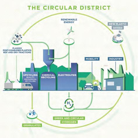
With the aim of developing technologies for mechanical and chemical recycling of waste, NEXTCHEM (MAIRE) has developed a Green Circular District Model (Figure 1) that consists of an integrated platform of green chemistry technologies, including upcycling and chemical recycling.
In this framework, MyRemono is a NEXTCHEM subsidiary that is focused on developing and licensing a novel and
efficient continuous depolymerisation technology for plastics chemical recycling, particularly for polymethyl methacrylate (PMMA), polystyrene (PS) and, in the future, polyolefins (PO).
MyRemono’s technology is located in the chemical recycling area of the Green Circular District Model, building on a chemical conversion process focused on the production of monomers from non-recyclable plastics. This technology can be applied to the above-mentioned polymers (PMMA, PS and PO), deriving both from industrial scraps and post-consumer waste, from which it can recover valuable monomers to produce virgin-like recycled polymers. This results in a viable solution to enhance plastics recycling, reduce the consumption of fossil-based materials, and address some of the main issues affecting mechanical recycling processes.
A tool for plastics chemical recycling
The depolymerisation technology can be categorised as a thermal-catalytic cracking process that results in monomers which can be recovered and reused for the production of a new virgin polymer.
The primary goal of this technology is to offer a valid solution to the growing global problem of pollution caused by plastic waste, capable of eliminating all the negative environmental and economic impacts generated by the practices currently used for the management of this type of waste.
This technology is a continuous process, based on a molten metal flow, maintained at a temperature ranging from 300 - 500°C. Polymeric materials to be treated are introduced in the form of grinded particles into the depolymerisation reactor. The proper mixing of the polymeric materials with the continuous molten metal flow improves the quality of both the breakdown of the polymers’ molecular bonds and the recombination of molecules to obtain the desired monomers, while reducing overall depolymerisation reaction times.
The depolymerisation reaction can be described as follows:
n When the polymers are immersed in the molten metal, the carbon-carbon bonds that form their molecules break down and the resulting radicals are fixed to the metal. In this step, a series of electrons is released, with consequent forming of aliphatic compounds.
n The molten metal assumes acid characteristics, the aliphatic components migrate to its surface, and therefore are protonated, becoming carbocations.
n Carbocations can undergo different types of reactions, such as breaking into two fragments, isomerising, or undergoing cyclisation. At the end of these reactions, they lose a proton, restoring the activity of the molten metal. They also migrate to the surface in the form of gas.
The main product generated by the reaction between polymers and the molten metal flow is a monomer-rich depolymerisation gas which, after emerging from the molten metal, is conveyed into a condensation or a cooling system.
The configuration of this latter part of the process is influenced by the type of polymer treated; for instance,
April 2024 HYDROCARBON ENGINEERING 24
Figure 1. NEXTCHEM’s Green Circular District Model.
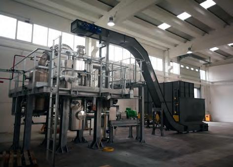
Figure 2. MyRemono semi-industrial prototype under construction.


Our brands supporting your Oil & Gas Projects: PERFORMANCE, ENGINEERED. trilliumflow.com/hydrocarbon-eng
pump solutions are meticulously engineered and field-proven to ensure your seamless Oil & Gas downstream plant operations.
Our
RO-FT API 610
Pitot Tube Centrifugal Pump
AHPB AHPB-D BB5-type API 610 Centrifugal Pump
GABBIONETA
® - TERMOMECCANICA POMPE
DSA BB2-Type API 610 Centrifugal Pump
PUMPS
ROTO-JET ®
when processing PMMA and PS-based polymers, a liquid final product is generated, thus requiring a final condensation system. When treating polyolefins, the depolymerisation technology generates mainly a gaseous final product which requires a cooling system similar to that used in hydrocarbon-fed ethylene and propylene plants.
The type of polymer treated also influences either the composition and the quantity of the noncondensable or useless fraction of the depolymerisation gas which, depending on its characteristics, could be vented after


passing through a vent gas treatment system or used as an energy source to partially fuel the depolymerisation process.
The continuous flow of the molten metal also favours its continuous cleaning, eliminating the solid products generated during the breakdown of the polymers’ molecules, without requiring any stop to the depolymerisation process.
The molten metal can be lead, tin, zinc, antimony, cadmium and magnesium and mixtures thereof, optionally mixed with other metals and/or acid components.
Industrial application
The depolymerisation technology has been tested through both lab-scale and semi-industrial scale prototypes (Figure 2) using different plastics waste and materials.
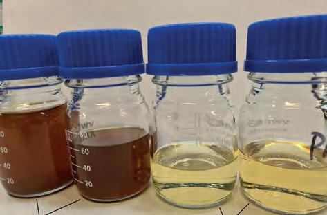
The most extensive tests have been performed using PMMA waste and materials (Figure 3), which could be consistently depolymerised to a high-quality recycled methyl methacrylate (rMMA). To perform the tests, a mixed-coloured PMMA regrind, with a granule size varying from 1 mm to 16 mm, was used as the main raw material.
The PMMA tests were primarily focused on identifying the optimal operational conditions for the depolymerisation process, in order to maximise both the recovery rate and the quality of the recovered recycled monomer rMMA. The tests achieved a recovery rate up to 95 wt% on the PMMA processed, with an MMA concentration up to 97 wt% on the raw rMMA.
Secondly, a series of tests were carried out to identify the most efficient and effective purification system, including tests on activated carbon filtration (Figure 4) and nanofiltration (Figure 5), with varying degrees of success.
At the end of this second phase of testing, a purified rMMA with a quality suitable to generate a 100% rMMA-made cast sheet was achieved (Figure 6). Moreover, samples of this purified rMMA sent to third parties for analysis and production tests have been received with significant interest.
Building on the results obtained during the PMMA testing campaigns, MyRemono is developing its first industrial plant, focused on recycling PMMA into a high quality rMMA with a 99%+ MMA content, characterised by a carbon footprint that is approximately 96% lower than that of virgin MMA.4 This new plant will work in a continuous mode for an expected on-stream factor of about 7680 hr/yr, with a PMMA regrind throughput capacity of 650 kg/h and an overall yearly throughput capacity of approximately 5000 t. The plant will incorporate the following main features:
n PMMA reception and storage area.
n PMMA quality control platform and charging system.
n A depolymerisation unit.
n A condensation and a two-stage purification unit.
n A rMMA storage and loading system.
The PMMA is fed into the depolymerisation unit where it is mixed with the plant molten metal. The contact between the PMMA and the metal greatly amplifies the effectiveness of the thermal energy, breaking down the PMMA molecular bonds in a fast and efficient way, and produces a methyl methacrylate rich depolymerisation gas, together with some solid residue.
April 2024 HYDROCARBON ENGINEERING 26
Figure 3. PMMA regrind.
Figure 4. Activated carbon filtration, from left not filtered and filtered samples.
Figure 5. Nanofiltration, from left not filtered, retentates and permeates.

PRECISE, ACCURATE, RELIABLE

HTRI is the recognized leader in process heat transfer and heat exchanger technology. Our flagship product, Xchanger Suite, is considered the most advanced thermal process design and simulation software for rating, simulating, and/or designing a variety of heat transfer equipment. Our calculation methods draw from over six decades of industry-specific research and data, ensuring unparalleled accuracy and reliability in our solutions.
Version 9.2.1 introduces a wide range of new and updated capabilities, including circulation boiling models for kettle reboilers tubeside falling film methods heat transfer/pressure drop methods for tubeside non-Newtonian flow methods for downflow tubeside condensation pressure drop
When precision is paramount, trust in HTRI.

HTRI.NET/SOFTWARE/XCHANGER-SUITE
While the gas is fed to the condensation unit to become raw rMMA, the solid residue is accumulated inside a dedicated section of plant and from there it is periodically removed and sent to disposal, without requiring any plant stoppage.
The raw rMMA is then fed to the purification unit where, thanks to a two-stage process, it is purified from both MMA low and heavy boilers, as well as from other impurities, generating a high quality purified rMMA.
At the end of the purification step, the plant will have generated the following outputs:
n A purified rMMA stream.
n A MMA high boilers liquid stream used internally to generate energy on site.
n A MMA low boiler gaseous stream used internally to generate energy on site.
n A water stream generated during the purification step, to be sent for recovery or disposal.
n A solid residue stream generated during the depolymerisation step, to be sent for recovery or disposal.


The plant, which will be located in Montorio al Vomano in central Italy, is presently at the permitting phase and is due to start operations by 2H25. According to first forecasts, MyRemono is expected to license the technology starting from 2030.
Future applications
According to the preliminary tests performed on styrene-based and olefin-based polymers, the technology appears suitable to efficiently recycle these types of plastics waste and materials.
Tests performed on high impact polystyrene (HIPS) highlighted an interesting crude rStyrene quality (Figure 7), as well as a high recovery level. Analysis of MyRemono raw rStyrene has also been conducted by a third party.
Throughout 2024, further tests will be performed, which aim to maximise rStyrene quality and recovery rates, as well as demonstrate the technology’s applicability to other polystyrene-based streams.
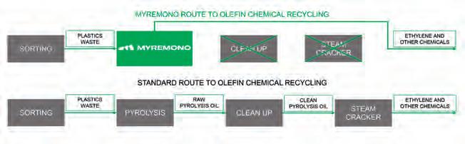
Tests with polyolefins demonstrated that the depolymerisation technology could work as a ‘polyolefin steam cracker’, returning these plastics into an ethylene- and propylene-rich gas, which could potentially be directly fed into the back-end of a steam cracker without requiring any further cracking process (Figure 8). MyRemono’s polyolefins application by-passes the clean-up and steam cracking phases, which provides a more efficient and cost-effective solution.
Between 2024 and 2025, tests will be performed aimed at confirming and optimising this additional technology application.
Conclusion
Boosting the scope of plastics waste recycling systems and establishing highly valuable plastics circular value chains is of paramount importance for the plastics and chemical sectors to thrive.
To achieve these objectives, the massive deployment of a combination of consolidated technologies and new recycling solutions is vital.
In this framework, MyRemono’s technology – combining advantages such as a continuous process, high energy-mass transfer ratio, short residence times and a high flexibility in treating different types of plastics waste within compact plants – is a valuable tool in the fight against plastics pollution, contributing to the decarbonisation of the plastic industry and strengthening the health of the plastics and chemical sectors.
References
1. ‘Global Plastics Outlook: Economic Drivers, Environmental Impacts and Policy Options’, OECD, (February 2022).
2. ‘Global Plastics Outlook Policy Scenarios to 2060’, OECD, (June 2022).
3. ‘Potential options for elements towards an international legally binding instrument by the co-chairs of the High Ambition Coalition to End Plastic Pollution’, High Ambition Coalition to End Plastic Pollution.
4. ECOINVENT 3.9.1 database for the conventional European production of virgin-MMA.
April 2024 HYDROCARBON ENGINEERING 28
Figure 6. MyRemono purified rMMA sample and rPMMA sheet 100% rMMA-made construction.
Figure 7. HIPS shreds and MyRemono’s rStyrene.
Figure 8. MyRemono route to polyolefin chemical recycling.

Kae S. Wong, Fabrice Cuoq, Giri Anupam, Omid Emamjomeh and Christoph J. Dittrich, SABIC Global Technologies B.V., alongside Rasha H. Daadoush and Vishvedeep Bhatt, Aramco, highlight how adsorption is an effective way to stabilise and remove chlorides in plastic derived oil (PDO) to protect downstream assets.
Plastics are ubiquitous in industrial and commodity applications. While more than 1 million t of plastics are produced and used every day, used plastics have created environmental challenges due to their long natural decomposition process. Global awareness about plastic pollution and its impact on ecosystems continues to grow. Producers are experiencing growing pressure from consumers to reduce plastic waste, and national
April 2024 29 HYDROCARBON ENGINEERING
governments, particularly in Europe, are introducing ambitious targets for a circular economy. All these factors are currently catalysing the development and implementation of plastic recycling technologies around the globe.
Plastic recycling recovers used plastic products at the end of their useful life and reprocesses them via mechanical and chemical recycling routes. Mechanical recycling uses mechanical processes such as sorting, washing, drying, grinding and compounding, to convert used plastics back into plastic products. Advanced recycling processes mostly rely on the pyrolysis of used plastic packaging, possibly after washing, into plastic
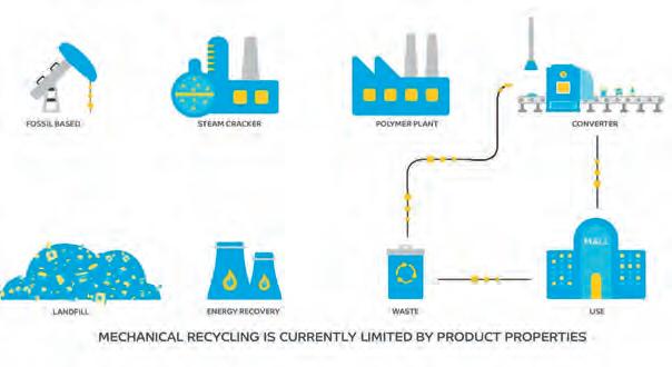
pyrolysis oil, which is also known as plastic derived oil (PDO). Both routes have their pros and cons and are complementary to each other (Figure 1). Mechanical recycling has the advantage of reprocessing used plastic directly in the converter, which is more energy efficient. Mechanical recycling has limitations on optimum recycling of plastic packaging waste because plastics are mostly recycled into applications that are not recyclable again after use. The product properties of mechanically recycled plastics are typically of lower value than for virgin plastics, which limits, combined with possible contaminants, the use in applications driven by high standards, for example in food or healthcare packaging. Mechanical recycling is mostly suitable to recycle pure thermoplastics, which are available via collection and sorting in large quantities. However, this collected waste also contains multilayer/multiproducts packaging applications, food residues and plastics which cannot be sorted for mechanical recycling for other reasons.
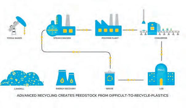
On the other hand, chemical recycling ensures mechanical and processing properties equivalent to the virgin material, making it an attractive recycling route for brand owners and customers that demand high quality packaging solutions. Chemical recycling enables the recycling of plastic waste streams for which there are no recycling solutions today. It recycles low quality, mixed plastic waste that is otherwise destined for incineration or landfill, back to the original polymer through pyrolysis to its molecular building blocks.
Other chemical recycling technologies that rely on solvolysis or biological/enzymatic degradation are being developed. However, these technologies are generally dedicated to the recycling of one specific polymer, e.g. PET, which requires high purity feedstock in a similar manner to mechanical recycling, and is generally not suitable for used polyolefins.
In the pyrolysis process, the used plastics are heated to approximately 400°C or more without adding oxygen, so the long chains cleave into shorter chains. Through the pyrolysis processes, the plastic waste is broken down to oil, (called pyrolysis oil or PDO) gas and a solid residue. The PDO is used as an alternative feedstock to replace fossil oil or naphtha and fed to a liquid cracker for the production of monomers
April 2024 HYDROCARBON ENGINEERING 30
Figure 1. (a) Mechanical recycling and (b) chemical recycling of used plastics.
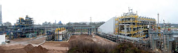
Figure 2. World’s first commercial unit for the chemical recycling of used plastic with the pyrolysis unit on the right and the hydrotreatment unit on the left (photograph taken in Geleen, the Netherlands in March 2023). Image courtesy of SABIC.

WE’RE COMMITTED TO YOUR EFFICIENCY
Our analyzers make tough SRU work a little easier
We know how hard it is to manage sulfur recovery unit (SRU) processes, and the levels of skill, concentration, and dedication your team needs.
That’s why we make sure you don’t have to worry about your analyzers, too. We’ve been designing industry-standard SRU analyzers for decades, focusing on reliability, longevity, accuracy, robust design, and ease of use.
We make analyzers for every part of the sulfur removal process – from SRU feed gas to the measurement of stack emissions, and everything in-between - so you get one convenient source for unparalleled engineering and support.
AMETEKPI.COM/SRU
such as ethylene or propylene that will be used to produce polyolefins.
Compared to fossil-based feedstock, PDO contains substantially higher amount of chlorides, nitrogen- and oxygen- containing components. Souchon et al mentioned that the organic chlorine (Cl) concentration in PDO can be up to two orders of magnitude higher compared to a fossil feed. 1 Those contaminants can have a detrimental impact on the assets, such as corrosion (from chlorinated and fluorinated species) and lead to fouling (from olefins and diolefins). As a result, further processing of PDO requires pre-treatment of the raw PDO to remove contaminants and reactive components, such as (di)olefins, chlorides, nitrogen- and oxygen-containing components. Additionally, unstable components in PDO can lead to precipitation and sedimentation of gum-like degradation products during transport and storage.
The PDO pre-treatment methods can be divided into physical and chemical techniques. Hydrotreatment is a chemical upgrading method which catalytically converts (di)olefins into saturated components,
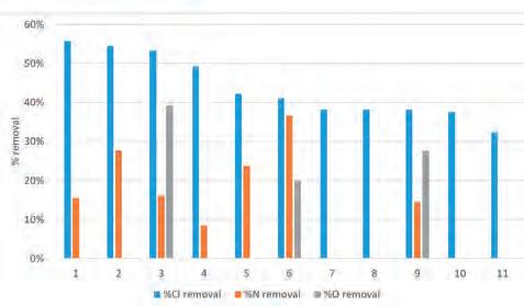
different solid adsorbents. The selected adsorbents include silica product 1 (1), clay product 1 (2), ion exchange resin (3), molecular sieve (4), clay product 2 (5), activated carbon product 1 (6), activated carbon product 2 (7), silica product 2 (8), washed activated carbon (9), clay product 3 (10), and calcium oxide (11).
nitrogen-containing components into ammonia, oxygen-containing components into water, and organic chlorinated components into hydrogen chloride. SABIC is building the first-of-its-kind commercial hydrotreating unit for this purpose (Figure 2). The physical upgrading methods, such as adsorption, absorption, filtration, liquid extraction and distillation, rely on removing the contaminants based on the physical properties of PDO components.
PDO characterisation
In order to validate effective upgrading methods, adequate analytical techniques are required. Understanding chloride speciation is critical as chlorides are amongst the most harmful components with regards to corrosion as they form hydrochloric acid during high temperature processing. Souchon et al summarise the standard methods of chlorine determination in crude oil and petroleum derivatives, e.g., ASTM D4929, ASTM D7536, UOP 779, etc. These standard methods only monitor the total Cl content, which may not be sufficient for Cl compounds originating from chlorinated polymers such as PVC. Cl speciation techniques (which are used to identify the type of chlorinated species) are essential to obtain a better insight for developing upgrading technologies and distinguishing organic chlorides from inorganic salts. 1-chlorobutane, 1,2-dichloroethane and 2-chloroethanol were the most abundant volatile organic Cl species identified in PDO samples analysed by gas chromatography with ICP tandem mass spectrometry, GC-ICP-MS/MS. 1
Pyridine and its derivatives, such as methylpyridines, are found in the naphtha fraction of PDO analysed by the 2D gas chromatography (GC X GC) coupled to four different detectors. 2 Regarding oxygenates, alcohols, ketones and ethers were detected.
SABIC recently developed a simple and affordable speciation method. The method uses a specific halogen detector (XSD) combined with 1D gas chromatography. Compounds are first identified using a separate GC X GC-MS system and added to the GC-XSD chromatogram using known retention time. Chloride salts and organic chloride compounds, such as chlorinated hydrocarbons, e.g., chlorethanol and chlorobenzonitrile, were successfully identified and quantified.
PDO upgrading via adsorption
Based on the PDO characterisation data, the heteroatoms in PDO are mainly polar in nature with low carbon numbers. Hence, some of the oxygen-, nitrogen-, and chloride-containing compounds in PDO can be adsorbed on solid adsorbents, such as activated carbon, solid alkali, solid acid, clays, silica, etc. Depending on the size and shape of the adsorbents, e.g., pellets, extrudates, powders, granules, etc., the adsorption vessel can be a fixed bed or a stirred slurry unit.
Figure 3 shows the reduction in the oxygen-, nitrogen- and chloride-containing compounds in the PDO, using selected solid adsorbents. All of the tested adsorbents show between 30 and 55% relative
April 2024 HYDROCARBON ENGINEERING 32
Figure 3. The reduction of oxygen compounds, nitrogen compounds, and chloride compounds in the used PDO, using
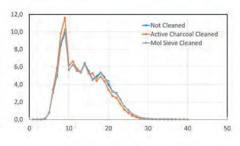
Figure 4. The changes in hydrocarbon composition (carbon number) for untreated and treated PDO using molecular sieves and activated carbon.
Cl reduction. These results have been obtained in batch (stirred batch slurry) experiments using these solid adsorbents at approximately 10 wt% and 24 hours contact time at 20°C. The initial atomic chloride concentration was 160 ppmw. 3
The hydrocarbon composition changes slightly when the PDO is treated with activated carbon (Figure 4). The activated carbon treated PDO became slightly lighter as seen in Figure 4 where a higher amount of low-carbon number components were detected. No significant hydrocarbon composition changes were observed for the molecular sieve treated PDO. As shown in Figure 5 for selected identified chlorinated species, the concentrations of 1,2-dichloroethane and 2-chloroethanol were reduced for a large portion after treatment, with both activated carbon and molecule sieves. On the other hand, the removal of 2-chloroethylbenzoate was less pronounced on the molecular sieve compared to 1,2-dichloroethane and 2-chloroethanol. This suggests a size effect where 2-chloroethylbenzoate is too large to properly enter the pores of the molecular sieve. Tests performed at lower adsorbent concentrations have shown that polarity of the species also impacts adsorption, where 2-chloroethanol was preferentially adsorbed.
Adsorption kinetics controls the adsorption rate, which determines the time required to reach equilibrium for the adsorption process. The adsorption transport model can give information regarding adsorption
Accurate liquid water measurements in EDC

pathways, which is important information for the development of the process and the adsorption system design. In order to determine the chloride adsorption kinetics, the dynamic behaviour of a fixed-bed column was fitted to the pseudo-first-order (PFO) and pseudo-second-order (PSO) kinetic models. The PFO model assumes the rate of change of solute uptake with time is directly proportional to the difference between saturation (equilibrium) and actual loading (still available adsorption capacity), which is generally applicable over the initial stage of an adsorption process. 4 The rate constant of adsorption is expressed as a first-order rate expression given in Equation 1:
(1)
The logarithmic form of the integrated PFO kinetic Equation (1) gives the linear expression in Equation 2:
(2)
Where: q t is the adsorbate loading adsorbed at time t (mg Cl /g ad ); q e is the equilibrium adsorption capacity (mg Cl /g ad ); k 1 is the rate constant (/min).
The PSO kinetic model assumes a quadratic dependency between the adsorption rate and the still


The SERVOTOUGH SpectraExact 2500F photometric analyzer delivers precise and stable measurements of liquid water in EDC.


Our high performance infrared sensing technology is ideal for tough measurements in demanding conditions, where reliability matters.
• Designed to handle flammable and corrosive samples
• Certified for hazardous areas
• Low maintenance requirements
Learn more at servomex.com
available adsorption capacity, and can be described by Equation 3:
(3)
The integrated form of the PSO kinetic Equation 3 can be linearised into Equation 4:
(4)

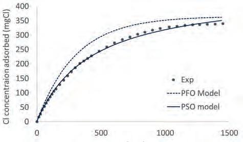
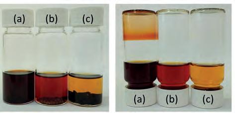
Where q t is the adsorbate adsorbed at time t (mg Cl /g ad ); q e is the equilibrium adsorption capacity (mg Cl /g ad ); k 2 is the rate constant (g/mg/min).
Figure 6 shows that the PSO model is in good agreement with experimental data over 1 day of run time. Therefore, the PSO kinetic model is applicable to describe the total Cl adsorption kinetics on activated carbon. This model can be used to design the adsorption column, as well as to predict the time when the adsorbent reaches saturation.
Finally, Figure 7 shows that the molecular sieve and activated carbon treated PDO is lighter in colour compared to the untreated PDO. This shows that the molecules which cause the colouration in PDO are partially adsorbed on the adsorbent. Additionally, the untreated PDO shows deposits of a semisolid and creamy layer on the bottom of the cylinder after 30 days of storage. On the other hand, no layer deposition was observed in the adsorbents treated PDO samples. This deposit layer is known as gum, which precipitates out of the solution with time due to ageing of the PDO. Treating the PDO with adsorbents, such as activated carbon and molecular sieves, removes gum and/or gum precursors from the PDO and increases the stability of the PDO. 5
Conclusion
The removal of chlorinated species in PDO is essential to protect the downstream refining and chemical assets from potential corrosion. Adsorption is proven as a simple and effective chloride removal step. It also stabilises PDO during transport by avoiding gum formation. The development of these upgrading technologies should, on one hand, focus on the contaminants removal efficiency, considering the carbon footprint impact of these additional upgrading steps. Lastly, in addition to mechanical and chemical recycling, other efforts, such as design for recyclability and closed loop recycling, should be promoted. Working side-by-side with partners across the entire value chain is essential to develop robust and diverse circular solutions and establish a new circular plastic ecosystem.
Acknowledgements
This study was funded by the Aramco Sabic Circular Solutions Technology Integration workstream.
References
1. SOUCHON, V., MALEVAL, M., CHAINET, F., and LIENEMANN, C. P., ‘Chlorine speciation in complex hydrocarbon matrices using GC-ICP-MS/MS’. J. Anal. At. Spectrom., 38, 1634, (2023).
2. THI, H. D., DJOKIC, M. R., and VAN GEEM, K. M., ‘Detailed group-type characterization of plastic-waste pyrolysis oils: By comprehensive two-dimensional gas chromatography including linear, branched and di-olefins’, Separations 2021, 8, 103.
3. SCHUCKER, R. C., CUOQ F., SUMPENA, K., and WONG, K., ‘Methods for treatment of mixed plastic waste pyrolysis oil’, WO2023279022A1, 2023.
4. VAREDA, J. P., ‘On validity, physical meaning, mechanism insights and regression of adsorption kinetic models’, J. Mol. Liquids, 376, 121416, (2023).
5. GIRI, A., EMAMJOMEH, A. R., and CUOQ, F., ‘Systems and methods for processing pyrolysis oil’, WO2021255591A2, (2021).
April 2024 HYDROCARBON ENGINEERING 34
Figure 5. The changes in selected chlorinated species in PDO treated with molecular sieves and active charcoals.
Figure 6. Sorption kinetics of total Cl adsorption onto activated carbon obtained using equations 1 - 4.
Figure 7. Gum prevention on (b) molecular sieve and (c) activated carbon treated PDO compared to the (a) untreated PDO.
Fatemah Jameel Fraidoun, Kuwait National Petroleum Company (KNPC), presents a case study in which the Mina Al Ahmadi refinery optimised its isomerisation unit in order to reduce the isomerate Reid vapour pressure and
The ever-growing global demand for cleaner fuels is challenging refineries to increase the production of low-sulfur and aromatic gasoline components.1 The light naphtha isomerisation process can reduce the aromatics from catalytic reforming products.2 A crucial barrier is the high isomerate Reid vapour pressure (RVP), which affects the MOGAS pool blend. As a result, extra quantities of other higher research octane number (RON) and lower RVP gasoline streams are sacrificed, or product sales quality is jeopardised. Reducing isomerate RVP is accompanied by a loss in octane barrels. Previous research has focused on enhancing product yield or RON. This article explains how a lower RVP product can be achieved while maintaining a high RON and presents guidelines for other optimisers that share the same goal.
The subject of the case study presented in this article is a C5/C6 isomerisation unit at the Mina Al Ahmadi (MAA) refinery in Kuwait, constructed of treating sections for hydrogen and light naphtha feed to remove sulfur, chloride, and moisture. The feed mixture is then heated sequentially by exchange with the effluent of two reactors operating in series. Raw isomerate is then sent to a stabiliser column for C4- components removal. The stabiliser overhead gas is treated in a net gas scrubber for

maintain high research octane number.
HCl neutralisation. The isomerate is routed to the deisohexaniser (DIH), in which further optimisation of the column’s streams achieves the required product specification. The DIH overhead stream contains the main isomerate composition of normal pentane (nC5), iso-pentane (iC5), and dimethylbutanes (DMBs). The bottom flow of DIH contains heavier C7+ components that contribute to lowering the final product RVP. Finally, a side cut from the column is recycled to the reactor with fresh feed. This stream contains normal hexane (nC6) and methylpentane (MPs), with RONs that can be further upgraded.
The author’s strategy is:
n Firstly, to understand the effect of feed composition on unit operation and desired product quality.
n Secondly, to record and maintain the optimal reactor operating temperature at which desired conversions are achieved.
n Thirdly, study the stabiliser column behaviour and construct an approach to identify the changes in feed composition without sample analysis.
n Finally, understand the DIH operation and its effect on product quality.
April 2024 35 HYDROCARBON ENGINEERING
It was concluded that the reactor feed composition affects the performance of all columns and, therefore, product quality. Consequently, the author presents an inclusive and systematic optimisation approach for feed composition and column operation.
Plan and strategy
The trial aims to reduce isomerate RVP from 14.1 to below 12.8 psi while maintaining around 87 RON. The reduction in nC5 to iC5 conversion results in a lower presence of the higher RVP iC5 components in the final product. Hence, the desired isomerate RVP is expected to be accompanied by a lower RON by at least two figures, i.e., 87 to 85. Therefore, familiarising oneself with RON and RVP for each component, as shown in Table 1, is the first step towards achieving the desired product quality. The isomerate composition is affected by several factors, such as operating capacity, fresh and combined feed composition, hydrogen purity, HLSV, reactor temperature, stabiliser and deisohexaniser column operation. The unit operating capacity during the trial is 75% due to feed unavailability. Despite this, the author was able to achieve similar results at a higher operating capacity. The hydrogen purity and HLSV remained constant throughout the trial and will therefore be excluded from the analysis.
Feed composition
Maintaining steady feed quantity and quality is the main factor affecting the results’ consistency. The fresh feed and DIH recycled stream affect the quality of combined feed to the lead reactor. Therefore, comparing reactor feed composition with remaining factors constructs a representative analysis of feed quality impact on product quality. Generally, lowering C4- and C7+ components reduces isomerate RVP. However, a steep reduction in C7+ may lead to disturbances in the stabiliser, and their absence in the DIH bottom will eventually lead to an increase in isomerate RVP. For higher than 50% operating capacity, it is advisable to maintain 2.7 - 4.1 mol% of C7+ components in the feed.
Three feed cases (A - C) with different compositions were selected for the trial, where feed cases A and B have similar C7+ components and case A contains more C5s. On the other hand, cases B and C have similar C5s, and the second is lower in C7+. The components were altered in these manners to understand the effect of feed composition on product RON and RVP.
Reactors performance
The isomerisation reactions, benzene saturation, ring opening and cracking occur in the lead reactor. Hence, the lag reactor inlet temperature is lowered to maintain paraffin to iso-paraffin conversion and avoid reaction reversibility. The focus is on achieving an optimal inlet temperature for both reactors at which DMBs production is maximised and nC5 to iC5 conversion is lowered without highly impacting product RON. For this study, lead and lag reactor inlet temperatures are reduced below normal operating conditions by 7 and 5°C, respectively. Most importantly, the lead reactor inlet temperature should not result in complete C7+ cracking to avoid eliminating its presence in isomerate and increasing C4- components. Different outcomes are expected for cases with varying numbers of reactors and catalyst types.
Stabiliser column
Promoting the stabiliser column separation allows for improving product RVP due to minimising C4- components slippage with the raw isomerate. Lifting a small portion of the isomerate C5s with the stabiliser off-gas will improve RVP with minimal effect on RON, especially at high DMBs conversion. The stabiliser reflux rate and bottom reboiling remained constant throughout the cases to assess the impact of different feed compositions on product quality. Double membrane technology can be introduced to recover hydrogen and LPG components from the net gas to accommodate losses in isomerate yield. Hydrogen can be routed to a hydrogen recovery unit, while LPG can be sent as a product.
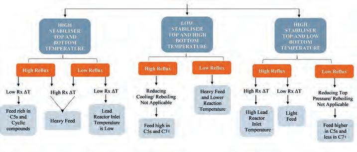
Deisohexaniser column
The most potent streams that process engineers can artistically optimise to impact isomerate quality is the DIH. The type of adjustment differs based on the reactor and DIH feed components.
April 2024 HYDROCARBON ENGINEERING 36
Figure 1. Reactor feed quality based on the stabiliser column operation.
Component RON RVP (psi) IC4 100.2 71.9 NC4 95 51.5 IC5 93.5 18.93 NC5 61.7 14.42 CP 102.3 9.18 22DMB 94 9.13 23DMB 105 6.85 2MP 74.4 6.27 3MP 75.5 6.27 NC6 31 4.59 MCP 96 4.17 CH 84 3.02 BZ 230 2.98 C7+ 82 2.1
Table 1. Reference for hydrocarbon components RON and RVP3
The guidelines in Figures 1 and 2 assist in identifying the changes in reactor feed quality without a sample and advise on the required DIH stream optimisation. The focus should be on optimising the column to allow the accumulation of DMBs in the system as this maintains higher product RON and lower RVP. It was found that this is more achievable at lower operating capacities than 100% as there is more flexibility in optimising the unit.
Results and discussion
Feed quality
The composition of the reactor’s three feed cases (A - C) were analysed to understand the impact of components, RON and RVP on product quality. The results revealed that feed RON and RVP only sometimes directly correlate with product RON and RVP. Therefore, the comparison was dedicated to specific components. As shown in Figures 3 and 4, an increase in higher RVP contributors (C4s, C5s, C7+) and a decrease in lower RVP components (nC6, MPs, DMBs) is directly proportional to high product RVP and lower RON.
The Case A feed contained 31 mol% of C5s and 3.3 mol% of C7+, twice the content of that in Case C. Moreover, the total nC6s, MPs and DMBs in Case A were lower than in Case C by 16.4 mol%. As a result, Case A product RON and RVP were 87.6 and 11.5 psi, respectively, while Case C product RON was 86.3 with a RVP of 10.6 psi. On the other hand, Case C feed contained higher 2.8 mol% nC6, MPs and DMBs, 0.9 and 1.67 mol% lower C5s and C7+, respectively, than Case B. The differences were minor however, with different stabiliser and DIH column operating parameters, the resulting Case B product RVP is 11 psi with a RON of 87. Although the isomerate RON for Case C was lower than the minimum requirement of 87, the reduction was considered minimal for the RVP difference of 2.2 psi.
In conclusion, the results of the three presented cases met the trial’s target of RVP below 12.8 psi while maintaining a higher RON. To illustrate, the original product RON was 87, with an RVP above 13.0 psi. From the author’s experience, the results shown in Case B are more achievable and optimal.
Reactors performance
The author prefers to keep the reactor temperature adjustment as the last optimisation option to preserve the catalyst lifecycle. The key is that the selected temperature does not result in lower RVP by a drastic reduction in nC5 to iC5 conversion, as presented in Figure 5. Therefore, the optimal lead reactor inlet temperature was maintained throughout the trial, while the lag reactor’s temperature was slightly increased to be aligned with the increase in nC6/MPs components. The temperatures were deliberately maintained constant to observe the stabiliser behaviour.
Stabiliser column
The stabiliser bottom temperature was maintained at a standard operating value with a reflux flowrate higher by 8% throughout the three cases. The higher C5 and C7+ components in the Case A feed resulted in a top temperature of 98.5°C against 96.9°C and 95.5°C for Cases B and C, respectively. At the same operating conditions, the higher the C4s, C5s and C7+ components in the reactor feed, the higher the stabiliser
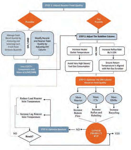
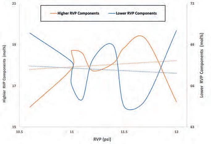
April 2024 HYDROCARBON ENGINEERING 37
Figure 2. Optimising isomerisation unit to reduce isomerate RVP whilst maintaining higher RON.
Figure 3. The impact of feeding higher and lower RVP components on isomerate RVP.
overhead and return reflux temperatures. Lifting higher RVP components with the off-gases is more achievable for Case C due to the feed’s lower presence of C4s and C5s. Consequently, reducing the stabiliser bottom temperature would increase Case C product RVP, and a higher temperature would decrease Case A RVP.
Higher return temperature and overhead cooling were required for Case A due to the feed’s higher C4 and C5 content. Subsequently, cooling requirements dropped for the other cases. Reducing the reflux rate would affect the separation efficiency, leading to more C5s in the raw isomerate. Therefore, slightly increasing the return temperature of Cases B and C would result in more effective separation. Although the top temperature may drop with the higher reflux rate, unnecessary energy losses due to heating the additional reflux shall be avoided. Moreover, the reflux return temperature must be aligned with the downstream net gas scrubber operating condition to avoid foaming.
In conclusion, based on the optimiser requirements, a decision can be made on what elements to sacrifice while operating the unit safely.
Deisohexaniser column
The DIH top and bottom temperatures, reflux rate, and overhead flowrate decreased along Cases A - C. On the other hand, DIH bottom flow and recycling increased. The column behaviour is associated more with the quality of DIH feed, which changed due to the different reactor feed quality and maintained stabiliser bottom temperature. A higher presence of C4 and C5 components in the DIH is expected when the reactor feed is lighter. Hence, an increase in the DIH overhead flow and reflux rate was observed in Case A. Subsequently, the bottom and recycle were reduced to maintain the overall column balance, resulting in higher product RVP and RON.
The Case C feed was lower in C4 and C5s and higher in lower RVP components, which resulted in lower DIH overhead flow and reflux rate. Consequently, the bottom and recycle flows increased to maintain material balance, contributing to lower product RVP with minimal reduction in RON. In conclusion, minimising product RVP while boosting RON requires lower iC5 and a higher DMBs presence in the overhead with maximising nC6 and MPs in recycle to increase DMBs conversion.

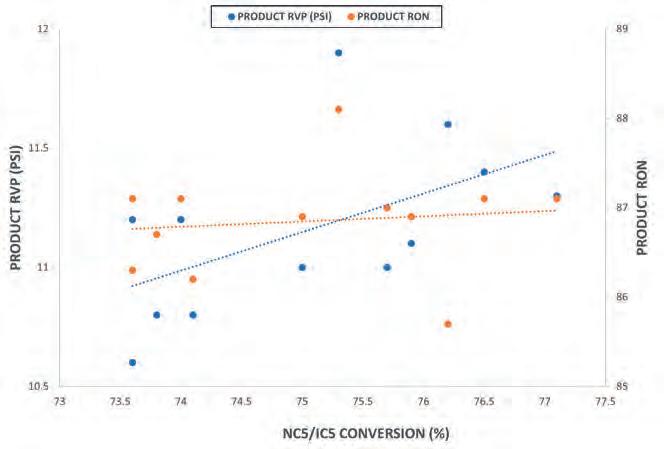
Conclusion
Isomerisation is a leading process for refineries that aim to compete in global oil markets with low aromatic and sulfur gasoline. Enhancing isomerate quality depends on operational planning requirements of higher yield or RON. Despite this, high gasoline RVP can be a challenge for refineries, and reducing isomerate RVP is expected to result in lower RON. An in-house exercise was conducted at the MAA refinery to minimise isomerate RVP while maintaining a high RON. Isomerate RVP was reduced from a maximum of 14.1 to 11 psi with a RON of 87. It is worth mentioning that an isomerate RON of 89 was achievable at an RVP lower than 12.8 psi. The conclusion of this trial is constructed in Figure 2 as a guideline to assist other optimisers in their journey to achieve similar objectives.
References
1. CISCHKE, S., ‘The Need for Global Availability of High Quality Fuels’, available at: https:// unece.org/fileadmin/DAM/trans/doc/2007/ wp29/Presentation%20OICA.pdf
2. HUSSAIN, N., ‘Euro Specifications of Gasoline fuel’, available at: https://thepetrosolutions. com/euro-specifications-of-gasoline-fuel/.
3. BENTAHAR, N., KHELASSI, S., and ABDELRAZEK, F., ‘Production of clean gasoline from condensate’, Egyptian Journal of Petroleum, 22(3), pp. 345 - 350, (2013).
April 2024 HYDROCARBON ENGINEERING 38
Figure 5. The effect of lower iC5 to nC5 conversion on product RON and RVP.
Figure 4. The impact of feeding higher and lower RVP components on isomerate RON.
Jaspreet Nijjar, Tracerco, UK, explores the benefits offered by specialist scanning and radiotracer technologies in optimising processes.
In order to remain competitive in the current economic climate, process optimisation is key for refining, petrochemical, and chemical processing industries. As plants and refineries are continuously expanding to meet current and future demands, units are being pushed well into and above their design capacity, limiting output from the unit and product purities. Only by having a complete understanding of their processes can operators make the decisions and changes required to deliver safer and more efficient production.
Tracerco has deployed specialist scanning and radiotracer technologies to aid operators with troubleshooting production problems and process

optimisation. These non-intrusive measurements provide a visualisation of real-time process conditions whilst they are online, enabling operational and mechanical issues to be identified at the earliest possible stage when adopting preventative approaches to process control. This has helped operators to maximise production output, reduce unit downtime and optimise maintenance schedules.
Diagnostic technologies
There are two main types of diagnostic, or scanning, technologies employed by Tracerco; gamma and neutron. Gamma ray absorption involves the use of a gamma emitting radioisotope, typically 60 Co or 137 Cs, placed on
April 2024 39 HYDROCARBON ENGINEERING
one side of the vessel or pipe and a scintillation detector mounted on the opposite side. The attenuation in radiation by the process media is measured, generating a real-time density profile from which the mechanical integrity of the internals can be inferred and any process issues, such as fouling, foaming, flooding and liquid maldistribution identified. These scanning technologies have been deployed on a variety of assets, including packed-bed and trayed towers, tanks, pipes, separators and reactors, whether the assets have been operating in normal, test or upset conditions. The results from Tracerco’s analysis of the data have provided operators with a clear picture into the performance of their assets, enabling them to take corrective action to troubleshoot and optimise their processes. The following case study demonstrates how Tracerco’s gamma scanning
technology empowered an operator to make a critical process decision to maximise yield.
Case study 1
In this case study, a customer was experiencing a reduction in production output and, after consultation, it was concluded that the debutaniser tower appeared to be the bottleneck for the unit. They identified unwanted heavy material in the overhead at high-rate conditions. Since the customer had no differential pressure instrumentation or sample points available, the pressure drop through the vessel could not be confirmed. The customer was able to increase feed over 20 - 25% of the tray design. However, they could not increase reboiler duty without sending heavy material overhead when reboiler boil up was increased. The customer’s simulations indicated, at those conditions, the vessel should not be operating near 100% flood. In order to obtain insight into the process conditions and verification of the simulations, the customer elected to perform three gamma scans (known as Tru-ScanTM) at low, medium and high rates on the debutaniser column at maximum feed rates (20 - 25% over design). The results of the gamma scans are depicted in Figure 1.
Using Tracerco’s FrothViewTM technology, the percentage froth height, equivalent to percentage tray space, was quantified from the scans (represented by the bars and numbers shown on the right hand side of Figure 1). Table 1 compares the tray spacing obtained from the technology vs the customer’s in-house simulations.
The data gathered from the Tru-Scan and FrothView surveys showed they were in fact experiencing flooding at higher rates than their in-house simulations were predicting. With this knowledge, the customer made a design modification to the trays by increasing the hole area on the active panels to reduce pressure drop. This enabled the customer to operate at the higher rates, without adversely effecting overhead material purities, and resulted in 15 - 20% additional throughput.
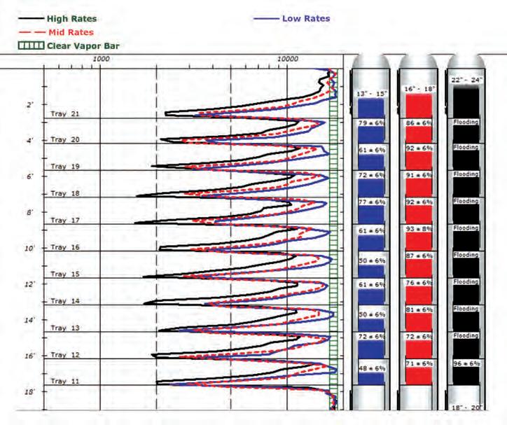
Neutron
The second diagnostic technology works on the principle of neutron backscatter. A small portable lightweight instrument containing a neutron source and detector, is placed against the vessel wall. The high-energy neutrons from the neutron source penetrate the vessel wall and interact with
April 2024 HYDROCARBON ENGINEERING 40
Figure 1. Gamma scans (Tru-ScanTM) performed under various operating conditions on a debutaniser tower.
(blue scanline in Figure 1) 50
50
(red scanline in Figure 1) 70
70
(black scanline in Figure 1) 100%, indicative of flooding 80
Table 1. Tracerco technology vs the customer’s in-house simulations
Rate % tray spacing Quantified using Tracerco’s FrothView technology From customers in-house simulations Low
- 70%
- 60% Mid
- 95%
- 80% High
- 90%

-------END TO END SULPHUR PROCESSING AND HANDLING SOLUTIONS
We are a world leading manufacturer of sulphur processing equipment as well as solutions for downstream silo/stockpile storage and reclamation, and bulk loading systems for truck, rail and ships.
ROTOFORM PASTILLATION
With 700+ systems in use by the sulphur industry, Rotoform is the world’s most widely used process for small to mid-capacity production of premium quality pastilles and offers unrivalled product uniformity and environmentally friendly operation.
SG DRUM GRANULATION
Where higher capacity is required, our SG rotating drum system is a fully automated, ‘once through’, sulphur granulation process based on a size enlargement process by continued coating of seed material.
ipco.com/sulphur
KEY FEATURES
Solidification capacity up to 280 mtpd.
Duplex steel belts alloyed for maximum lifetime.
Pastilles according to SUDIC premium quality spec.
KEY FEATURES
Capacity up to 2,000 mtpd.
Single pass, no need for screens.
Process simulation to suit all conditions.
Simple operation, precise control.
Pastilles Steel belt Rotating shell Heating channel Heating channel Cooling spray Sulphur nuclei particles Sulphur granules Sulphur spray Rotating drum Flights
the process media. If the process media is hydrogenous, the high energy neutrons are diffused and scattered back to the detector as slow neutrons. In this way, the response at the detector is directly proportional to the hydrogen content of the media, i.e. the more hydrogen in the media, the more neutrons are scattered back and the higher response seen at the detector. This technology can therefore be used to measure the levels of different
phases in a vessel, e.g., vapour, foam oil, emulsion, water and solids. The neutron backscatter technology is widely implemented by operators to give them accurate inventories of their storage tanks and diagnose interface control issues in separators. An example of how the neutron backscatter technology aided with optimisation of a separator’s performance is outlined below.
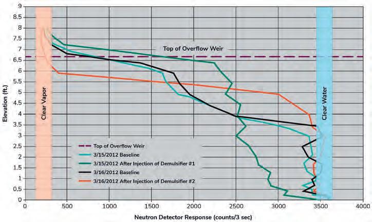
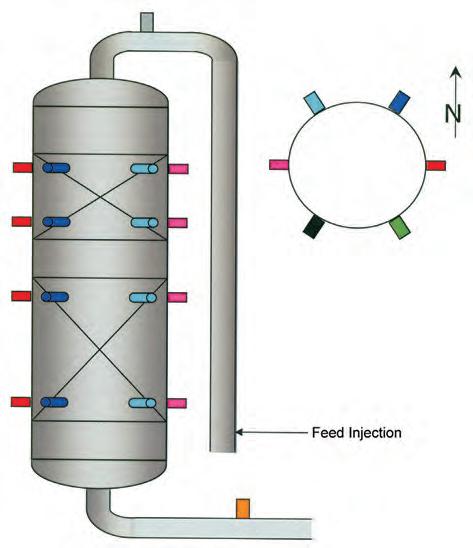
Case study 2
A refinery customer requested neutron backscatter scans to assist with evaluating the effectiveness of two different demulsifier chemicals on their separator. Four scans were performed on the separator: two baseline scans and two following the addition of the two different demulsifier chemicals. The results are shown in Figure 2.
The first baseline scan (light blue line) showed that there was approximately 1 m of clear water at the bottom of the separator. A gradual reduction in response was observed from the 1 m elevation, up to the top of the weir which would be caused by emulsion. The second scan (green line), performed after the first demulsifier chemical was added, showed a severe emulsion had been created, with evidence of less than 15 cm of clean water in the bottom. The third scan (black curve) was a baseline scan performed the next day which showed that the conditions inside the separator had returned to the baseline conditions of the first scan. The fourth scan (red line), following the addition of the second demulsifier chemical, showed that the emulsion that was on top of the water level had been removed. This data enabled the customer to select the second demulsifier chemical to optimise their process by effectively controlling the dosing regime based on real-time conditions.
Tracer technologies
Radiotracers have been utilised in tandem with Tracerco’s other diagnostic technologies on a number of different vessels including reactors, separators, fluid catalytic cracking (FCC) units and pipelines to generate the critical process insights required to reduce maintenance and operational costs and increase production rates. These technologies involve injecting a phase-specific radiotracer, which is carried in a specific phase flow, into the inlet of the vessel. Tracerco has a variety of radiotracers compatible with solid, liquid and gaseous phases, enabling every phase flow to be measured. Several sensitive detectors are positioned on the inlets and outlets of the vessel, enabling the passage of the tracer to be monitored.
April 2024 HYDROCARBON ENGINEERING 42
Figure 2. Neutron backscatter scans performed on a separator: two baseline and two following the injection of demulsifier chemicals.
Figure 3. Position of detectors for distribution and residence time study performed on a gas phase reactor.
Gain greater process clarity
It’s time to optimise your processes
Tracerco uses innovative technology to provide critical insights into what’s going on inside your processes. Our insights let you optimise efficiencies, increase productivity and troubleshoot production problems, at a time when you need it most.
And you’ll be in the safest of hands – we provide the widest range of scanning and tracer services on the market. With over 65 years’ experience, we’ve saved companies around the world billions.
Scan the QR code to find out how we can help you gain greater process clarity.

tracerco@tracerco.com
tracerco.com
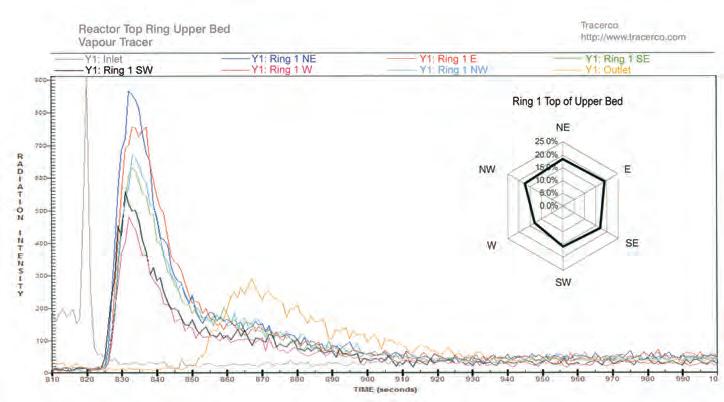
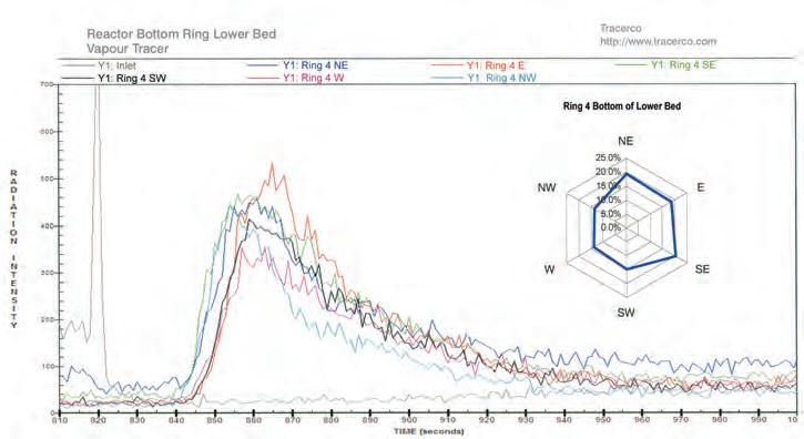
When the tracer flows past the detector, its response and time is registered. Information on flow distribution and timing can be derived from analysis of the detector responses, allowing flow dynamics and the behaviour of solids, liquids and gases within the vessel to be measured. The following case study illustrates how the results from these measurements allow operators to diagnose integrity problems, determine distribution uniformity and make modifications to improve efficiency using data driven insights.
Case study 3
Tracerco was contacted to assist with start-up issues that a customer was experiencing with its gas phase reactor containing two fixed catalyst beds. They were experiencing lower than expected conversion upon startup and suspected maldistribution to be the cause. A distribution and residence time study was performed by positioning four rings of six detectors on the reactor at elevations highlighted in Figure 3.
The responses measured from the detectors at the top of the upper bed and bottom of the lower bed are shown in Figures 4 and 5, respectively.
Figure 4 shows that for the top of the upper bed, almost 20% of the flow was measured near each of the NE and E bearing detectors with approximately 17% at the NW and SE detectors. 11% and 8% was observed at the SW and W detectors, respectively. Since each detector should have been equally distributed (16.7%), a total of 40% to the NE and E and only 20% to the SW and W indicated serious maldistribution was present.
Figure 5 shows that the detector responses were more similar to each other for the bottom of the lower bed, however there remained a 58% to 42% flow bias to the east side of the reactor. The mean residence time (MRT) was measured at 36.8 seconds from the upper bed top ring to the lower bed bottom ring and the overall MRT was 53.4 seconds.
The data from this study enabled the operator to identify the cause of their sub-optimal reactor performance. At the next scheduled shutdown the customer changed the inlet distributor and redistributor between the beds and when the reactor was restarted, the performance had significantly improved. With the process and performance insights gained from the reactor distribution study, the customer was able to realise the value of the investigation and avoided any further lost yield or downtime costs.
Summary
Diagnostic service technologies can be deployed on a variety of different industrial assets to provide non-intrusive diagnosis of production or integrity issues in real time. This enables operators to see the necessary corrective action required to minimise downtime and optimise their processes. Companies like Tracerco can deliver innovative technologies that enable operators across the globe to make informed decisions on the condition of their assets, helping industry achieve safer and more efficient production.
April 2024 HYDROCARBON ENGINEERING 44
Figure 5. Responses from the detectors measured at the bottom of the lower bed.
Figure 4. Responses from the detectors measured at the top of the upper bed.
Mark Breese, Yokogawa RAP, considers the importance of digital control of work (CoW) systems in promoting more intelligent operations and an improved safety culture in the downstream industry.
Process optimisation, when broken down into its constituent words, can be summarised as: (process) ‘a series of progressive and interdependent actions or steps taken in order to achieve a particular end’ and (optimisation) ‘the act of making the best or most effective use of a situation or resource’.
Companies often have a number of concerns when moving from the standpoint of simply ‘getting the work done’ to ‘getting the work done safely’. It is unfortunate that, on occasion, safety only becomes important after an incident has taken place.
Improved safe working must sometimes jump a series of stalling objections before being put into place; some common examples being:
n The belief that the company does not have the time or money to devote to safe control of work (CoW).
n Some companies may prefer to first improve injuries in the field due to employee time based maintenance (TBM) shortages and workers’ misunderstandings of their jobs rather than accidents related to work permit issuance.

n With ageing workforces, there may be a lot of opposition to digitalisation on the job site. Digitising everything may put a heavy workload on young people in the field (teaching older workers and registering on their behalf).
n Companies may believe that digital CoW systems are smart, but that there are only few major benefits to implementing them. This is because they may believe that it is not significantly different from existing paper systems.
n Companies may have a deep-rooted culture of central management using paper, Excel, etc., and believe that it will take a long time to change the fundamentals.
So what do these objections have to do with process optimisation? At best, they are excuses for not wanting to change, and at worst they are deliberate reasons why companies do not want to optimise safe working processes because they are classified as secondary to the main processes of making things or doing the primary work of the site. As such, they are not considered worthy of the same level of effort, when the opposite is often the case. Resolving safe working
April 2024 45 HYDROCARBON ENGINEERING
practices can have a huge positive effect on the main processes and the company’s bottom line.
It is important to consider each objection and how they relate to both process optimisation and CoW.
A route to save both money and time without compromising safety
Fundamentally, a lack of time and money is an issue encountered by many, particularly when markets are soft, and by general reductions in the workforce over time. This is a catch-22 in that saving both time and money requires more efficient working, but it will almost always take time and, to an extent, cost, to achieve it.
At its heart, CoW is about ensuring all risks are mitigated, all forms of energy are removed from the work area, and everyone who needs to be aware of the work is aware and has agreed to it happening. Process efficiency savings come from an optimised best practice workflow and an easier ability to see and sequence work so that there are no dangerous simultaneous operations, and everyone knows where and, more importantly, when, they need to be active.
This ensures there are as few delays as possible because work can be more easily planned and run through the system, without taking any shortcuts on safety. This, in turn, leads to optimised maintenance processes that ensure the primary

processes benefit from the maximum uptime possible, whilst overdue maintenance backlogs should tend towards zero.
Improved maintenance processes with clarity of instruction
TBM is a well-used principle and generally works well, particularly as plants gain experience over the typical service life of their installed items. The problems with it tend to arise as the overdue maintenance backlog creeps up, which it can do if maintenance activities are not completed in line with the time allocated for them. The reasons for this are commonly due to overruns of other work, conflicts between activities, parts shortages, or people not being available on time.
Workers not understanding their jobs is almost always the fault of the people generating and issuing the work as opposed to the workers themselves.
Most incidents have at their root an inadequate assessment of risk, often allied with an incomplete or unclear set of instructions.
A good digital CoW system can help solve both issues by allowing better planning, removing time pressures and reducing overdue workload, whilst helping to ensure a clear and robust risk assessment allied with clear instructions on what must be done to complete the work safely.
Additionally, the improved view of activities offered by digital CoW systems should enable visibility well in advance of whether there may be conflicts and should remind supervisors to check on parts availability before releasing work.
Gaining the benefits of worker experience
Opposition to digitalisation can be observed in several ways. At its root is a fear of the unknown that leads to a level of resistance to change.
In every conversation with more experienced personnel at site, the discussion is never about fear of the system, but rather about how they can ensure that their skills can be transferred properly to the rest of the workforce to ensure that tribal knowledge and understanding can be switched to corporate understanding and consistency.
Where companies only have a small number of access rights to the system, this tends to result in a wall between the general workforce and the people who are assigned access to the system. Good integrated safe systems of work (ISSOW) should always allow the broadest level of access possible and be role-driven so everyone who needs to be involved in safe working processes, including contractor workers, can be. This helps to foster a much more inclusive culture.
As an aside, it is poor practice to try signing for someone else because it means there is no true accountability for activities. By everyone having their own access and rights, companies are doing their utmost to ensure that a robust system is in place, with each person being accountable in line with the competence assigned to them by their roles.
A best practice workflow, and an intuitive, easy-to-use interface, will take away most fears. Older workers do indeed have important lessons that they can teach their
April 2024 HYDROCARBON ENGINEERING 46
Figure 1. The many advantages that a good digital control of work system can bring.

Learn more about our smart actuators PROFOX-X ACTUATORS
THANKS TO CERTIFICATION profox.auma.com
AUMA PROFOX-X
SAFETY

younger colleagues whilst still being open to new ideas themselves. It is this inclusivity that really helps in the process of optimisation.
Understanding the advantages that CoW systems can offer
Digital and paper systems really should not be any different at their fundamental level. Both systems aim to ensure that all the safe working factors are implemented, including local site, national or international rules.
However, not all digital, or indeed paper, systems are created equal. A good digital system should offer users a more intelligent way to manage their safe working practices.
Any ISSOW should ensure that all the information is shown in the most visible and consistent manner possible. The great advantage of digital systems is that they can offer a level of granularity that is not possible with paper-based systems. They also offer a more intelligent solution in several ways, such as:
n Lessons learned/updates are easier to apply.
n They can incorporate intelligent questions that apply filters to remove spurious items.
n They can incorporate a knowledgebase to help with risk assessments.
n They can automatically tie isolations to permits to ensure that permits cannot be released without isolations being in place. They can also ensure that isolations cannot be removed until all permitted activities are complete.
n They can link to monitoring activities such as post-issue monitoring, fire watches and monitoring of defeats.
n They can provide better visibility of work, covering exclusions and potential simultaneous operations (SIMOPS) far more easily.
A digital permit to work (PtW) system is not just about taking a paper system and converting it to digital forms because, whilst some efficiency is gained, the only thing that is optimised is that the route to an incident becomes faster. Digital systems, such as Yokogawa’s RAP4 software for CoW, offer users an easier-to-manage system that enhances the work that they are already doing by enabling workers to concentrate on what really matters, by removing items that are unnecessary for the work at hand. Paper systems simply cannot achieve this, which means the process of permitting can only be optimised to a certain point before the next logical step in the continuous
improvement process, which has to be the digitisation of the system.
Improved ways of working
Change can be daunting, and the longer a company becomes used to a particular way of working, the harder it can be to change. However, if the recent COVID-19 pandemic taught organisations nothing else, it certainly has exemplified that when there is a need, companies can move towards new ways of working. At its heart, this concern is often a fear of starting the journey, which may be borne from past experiences, fear of having to learn new things, fear of widening responsibility beyond a few key people, and more.
However, as noted earlier in this article, a good digital system is really all about offering a more intelligent way to manage what is already being done today and, in so doing, gaining the advantages that it brings to safe working and optimisation of processes.
Moving to a digital system offers a smoother path to the future. The rules and regulations that companies abide by will change over time and safety systems must also change to keep up with the times. Digital systems offer the easiest way to do this and maintain version control.
A required culture change
Plants often require a change or improvement to their culture, but are not always sure how to achieve it. A core commitment tends to make cultural change stand or fall: the need for a complete and unwavering commitment from the organisation’s management to get everyone involved.
This involvement does not just mean information-sharing, which bulletins or newsletters can easily accomplish. Encouraging and enabling workers to become genuinely involved in the processes of safety leads to the opportunity for great strides in the optimisation of their working processes.
This should extend to contractors too, as often sites do improve culture and incidents drop, but they see contractor incident numbers remaining stubbornly high. This stresses the need to incorporate the complete supply chain into a single safe way of working, where everyone has full visibility of where they can work, and what they are allowed and required to do and when.
Smarter, safer working
In summary, work process optimisation is all about smarter, safer working. Yokogawa’s OpreX Control of Work solutions can help companies to achieve the cultural and system improvements necessary to achieve robust, repeatable, and consistent safer working practices, which enable real optimisation of working processes without risking worker safety.
Whilst the change to a digital system from the original system – be that paper, older electronic systems, or a mixture of the two – can be a cause for concern, a capable digital system, such as Yokogawa’s RAP4 software – and the benefits that can be gained by implementing its modules – will enable a critical foundation of safety for the future.
April 2024 HYDROCARBON ENGINEERING 48
Figure 2. Five steps to excellence in control of work.

Eric Sallee, OsecoElfab, explores how advances in rupture disc technology can help refineries and chemical processing facilities minimise overpressure risks and reduce emissions.
In refineries and chemical processing facilities, maintaining safety from over-pressure events and preventing leaks and emissions is of paramount importance. Over-pressure events and uncontrolled releases present risks that could cause significant injury or harm to people, the environment, equipment, and operations. To mitigate these risks, plant operators install safety devices such as pressure safety valves (or pressure relief valves) and rupture discs.
This article examines how advances in rupture disc technology minimise overpressure risks and actively reduce leaks and fugitive emissions.
Why rupture discs are game-changers
Plugging, corrosion, product loss and contamination are just some of the challenges caused by unchecked leaks and fugitive emissions. The ramifications can be far-reaching, including endangering employees and the public, incurring fines or cleanup fees from regulatory agencies, and causing unplanned shutdowns that lead to lost production. The importance of minimising leaks and emissions cannot be overstated.
Rupture discs serve as a critical line of defence in ensuring the integrity and safety of industrial operations. Also known as bursting discs, they are designed to safeguard
April 2024 49 HYDROCARBON ENGINEERING
against potential harm by activating or ‘bursting’ at a predetermined pressure. This prevents excessive pressure buildup to ensure the overall integrity of the equipment and protect against catastrophic incidents. As the discs remain leak-tight until activation, they are also highly effective at minimising unwanted emissions.
Traditional rupture disc technology
Traditional rupture discs utilise a three-piece configuration, consisting of the rupture disc plus an inlet and outlet holder. Pre-torque holders are often used to ensure proper

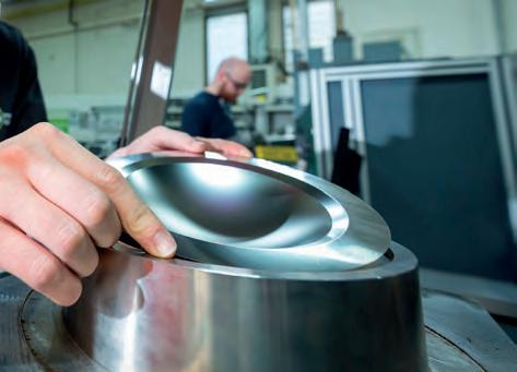
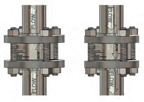
rupture disc seating and installation. These holders allow controlled torque application to cap screws, ensuring an optimal disc-to-holder seal. They also facilitate easier cleaning, inspection, and orientation verification of the disc. Proper device specification, correct installation, and ongoing maintenance are crucial to ensuring the rupture disc remains leak-tight.
For decades, pre-bulged and composite rupture discs were the industry standard for refining and petrochemical applications. However, while effective for simple applications, they have limitations when it comes to minimising leaks, reducing fugitive emissions, and improving system performance. They are not ideal for relief valve isolation, they are prone to fragmentation, and they may cause damage or obstruction to sealing surfaces. Additionally, these designs face challenges in cyclical processes and negative pressure applications. Although still used in certain holders, new technologies have surpassed their capabilities.
Scoring technologies coupled with annealing processes emerged, revolutionising rupture disc performance. The new, scored rupture discs could be either forward-acting or reverse-buckling, and offer significantly higher operating ratios, non-fragmenting designs, and precise activation pressures, outstripping the performance of pre-bulged and composite discs.
Innovations in rupture disc technology
Welded assemblies consist of the rupture disc and holder, but the components are pre-assembled at the factory using high-integrity welds. The utilisation of one-piece units offers several advantages including the following:
n Enhanced safety: the hermetically sealed assembly is more reliable and removes potential leak points. The likelihood of unplanned downtime due to leakage is significantly reduced.
n Simplified installation: with the rupture disc and holder already assembled, installation becomes more efficient with less room for error. Improper torquing, mismatched discs and holders, incorrect disc orientation, inadequate cleaning, corrosion damage, and worn-out holders are now a thing of the past.
n Reduced maintenance: the high-integrity welds and sealed design minimise the need for frequent inspections and maintenance, saving time and resources. Maintenance teams can focus on other critical tasks.
By combining a rupture disc and holder in a factory-assembled configuration using high-integrity welds, welded one-piece assemblies provide a hermetically sealed assembly that eliminates many common issues associated with overpressure-relief systems and can effectively reduce potential leak points in their systems. This hermetic sealing not only minimises the risk of damage and injury, but also improves overall safety. With a reliable and sealed assembly, the likelihood of unplanned downtime due to leakage is significantly reduced. This translates to improved operational efficiency and cost savings.
April 2024 HYDROCARBON ENGINEERING 50
Figure 2. Rupture disc being assembled into a welded assembly.
Figure 1. Common three-piece rupture disc assembly in holder installed.
Figure 3. Welded configuration of rupture discs.
Another key advantage of one-piece units is the elimination of installation errors that can occur with other disc and holder configuration. Improper torquing, mismatched discs and holders, incorrect disc orientation, inadequate cleaning, corrosion damage, and worn-out holders are all potential concerns that can lead to leakage and compromise system integrity. Moreover, with factory-assembled units, installers no longer need to evaluate the condition of holders or worry about wear, corrosion, or damage. This streamlines the installation process and allows maintenance teams to focus on other critical tasks.
Case study: a petrochemical facility’s journey to reducing emissions
Take the case of a petrochemical facility in Louisiana, US. After working with the operator, the rupture disc manufacturer carried out a complete survey of all the existing rupture discs in the facility and advised the operator of the applications that would benefit from moving to the welded one-piece configuration. By transitioning from traditional three-piece discs to the welded one-piece design, they cut fugitive emissions by 30 - 40%.
This move was not just environmentally sound, it also aligned the facility with local regulations, demonstrating full compliance and avoiding penalties.


Choosing wisely: the right rupture disc for the right job
Selecting the right rupture disc type for the equipment, process and media is crucial for achieving optimal performance and reliability in the pressure safety system. It involves understanding factors such as a rupture disc’s flow characteristics. The flow rate of a rupture disc upon activation is described using the loss coefficient designation ‘KR’. A lower KR value indicates a lower resistance to flow and therefore higher flow rate for the same nominal bore size. When a rupture disc is used that has a lower flow resistance value, or KR, the pressure drop through the disc will be lower, thereby allowing more of the process media to flow through in a certain set time-period.


Advanced rupture disc and explosion protection solutions Oseco Safety Cartridge Single-piece Solution for Chemical Processes – Leak-free – Easy to install – Reduce emissions – Contain hazardous chemicals LoKr Rupture Disc The Next Generation of Design and Engineering in Pressure Relief Technology – Best-in-class KR value – Superior reliability – Improved process performance – Flexibility when choosing piping sizes osecoelfab.com For more information: email: sales@osecoelfab.com call: 0044 191 293 1234 | 001 (918) 258-5626 20667 OE Hydrocarbon Eng. Magazine Ad (210x146mm).qxp_Layout
1
Figure 4. Non-invasive burst detection sensor installed on a rupture disc assembly.
1 15/03/2023 10:00 Page
A rupture disc featuring a lower KR value offers a trio of critical benefits to operators at refineries and chemical facilities:
n Pressure relief is both faster and safer.
n By keeping the pressure drops beneath the installed pressure relief valve low, operators can effectively combat valve chatter, ensuring reliable performance.
n A lower KR adds flexibility to the piping sizing by enabling reduced line sizes while maintaining the required flow rates, potentially unlocking cost-saving opportunities during system design and upgrades.
The latest advancement in rupture disc technology combines the lower KR disc technology into a sealed one-piece welded assembly. This configuration gives operators the benefits of both the lower flow resistance in a design that enhances safety, simplifies installation and reduces maintenance.
Beyond pressure relief
Burst detection is an important capability to be aware of when selecting rupture disc technology. A burst detection sensor will instantly detect when a disc ruptures due to an overpressure or vacuum event and send a notification to the operator.
Burst detection sensors work by having membrane detectors installed on the vent side of rupture disc assembly. When the rupture disc activates, or bursts, the process


media then opens the circuit and sends a signal. This lets operators know immediately where a pressure event has occurred, enabling them to take swift action to replace the disc, and minimise product loss and process downtime.
The human element: training for installation and maintenance
No technology, however advanced, can operate in a vacuum. Training to ensure proper rupture disc orientation installation and maintenance is essential to prevent hazardous leaks, resulting in loss of product, contamination, fugitive emissions, and corrosion. Rupture disc manufacturers often provide on-site training to ensure thorough understanding and correct installations. They will also typically conduct a site survey of a facility to inspect and inventory the supply and condition of existing rupture discs. Using the survey, they will be able to recommend the best pressure relief technology to meet operational needs.
Safe, efficient, compliant
In summary, rupture discs are key in preventing catastrophic damage and injury. However, selecting the right disc also has the potential to unlock increased efficiency and environmental compliance. Embracing innovations such as the welded one-piece units and lower KR technology can elevate the safety and operational performance of any facility, enabling operators to make the best use of their investments in pressure relief technology.


Need a reprint? www.globalhydrogenreview.com The leading publication for the global hydrogen sector Subscribe for free

Sunil Musali, MOGAS Surface Engineering, USA, discusses the use cases for thermal spraying and laser cladding in surface engineering.
Surface engineering is the science and art of enhancing surface properties of a material by utilising one of many available processes such as thermal spray, laser cladding, plating, thin films (chemical vapour deposition, physical vapour deposition, plating, etc.). Process choice is dependent on several factors including base material properties, in-process conditions, end requirements of mechanical/chemical properties, desired surface conditions and, most importantly, cost. Thermal spraying and laser cladding play a significant role in surface engineering due to their versatility of material choices and process conditions.
Thermal spraying
Thermal spray is a process technique used to enhance the surface properties of a component by applying coatings to its surface. As the name suggests, ‘thermal’ is the heat source and ‘spray’ is the feedstock utilised to melt, partially-melt or soften the feedstock and accelerate towards a prepared substrate to form coating and build up in layers (Figure 1).
Commercially available thermal spray processes include twin wire arc, plasma (air plasma spray [APS], vacuum plasma spray [VPS], low pressure plasma spray [LPPS] and Cascade), combustion spray, high velocity oxygen fuel (HVOF), high velocity air fuel (HVAF), and cold spray, etc. Each one of these processes exhibits unique operating conditions that produce a versatile range of subsequent coating properties. Desired coating properties including hardness, porosity, bond strength, toughness, ductility, etc. are achieved by choosing one of the stated thermal spray processes and
April 2024 53 HYDROCARBON ENGINEERING
manipulating process parameters. Coatings can be designed to withstand various severe service conditions such as wear (abrasion, erosion, etc.), complex corrosion, thermal shock, impact, and/or a combination of these.
Chrome carbides and tungsten carbides (Figure 2) are desirable options in the valve industry where abrasive wear and corrosion due to sulfidation, chloride and organic acids are present. However, where corrosion and severe thermal shock are
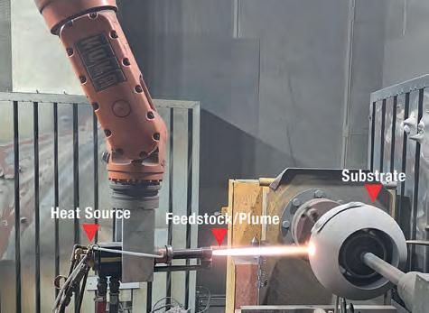


the primary drivers, nickel and cobalt based spray and fuse self-fluxing alloys perform better due to their denser microstructure (Figure 3) and metallurgical bond to the substrate.
Laser cladding
Laser cladding is a hybrid process between welding and thermal spray, which utilises laser as a heat source to melt the feedstock and create a molten pool on the surface of the workpiece. The result is a metallurgically bonded clad on the component with very little heat affected zone (HAZ), and minimal to no post treatment required. Due to less heat input than conventional welding, distortion is minimal on the components. Higher build rates are achieved and, in most cases, one layer of clad is sufficient. Metals, alloys, metal matrix composites (MMCs), carbides, etc., can be successfully clad.
When a metallurgical bonded coating/clad is necessary and the components cannot be exposed/heat-treated at elevated temperatures, laser cladding is a viable option.
Laser cladding is a fast moving technology in a variety of applications such as cutting tools, drilling tools, automotive, jet engine turbine parts, earth moving equipment, agriculture machinery, oil and gas, refining, and several other industries due to its versatility of material choices and metallurgical bond. Most recent developments in the laser clad technology include high speed lasers, where a flash clad can be applied to the component at a quicker pace, reducing processing times and minimising post finishing time as well. This may not be an ideal fit across the board, but it is very attractive in some applications.
Thin films
Thin films are also a family of processes which deposit a micron or less, such as electro plating, chemical vapour deposition (CVD), physical vapour deposition (PVD), evaporation, sputtering, etc. For decades, plating played a significant role in several applications for corrosion, wear, electrical conductivity, etc. However, the need to improve bond strengths, chemical compatibility and much denser coating structures has driven technologies further and resulted in PVD and CVD type coatings. These types of processes produce chemical and metallurgical bonds at microscopic level, and thicker than 1 µm coatings are achieved (in some cases, several microns thick). These types of processes open a blanket of materials (metals, alloys, carbides, nitrides, etc.), which can be deposited while plating is limited to pure metals. The need to phase out chrome plating due to health and environmental factors associated with hexavalent chrome has driven the demand for replacement where CVD and PVD type coatings have found their place for some applications.
Summary
Thermal spray has proven to be widely used in the industry due to its versatility of process conditions, wide array of materials, minimal heat input, range of thicknesses, etc.
The laser clad process is starting to play a significant role in the industry due to its ability to produce metallurgically bonded clad with minimal HAZ and distortion to the components, and in most cases, there is no need for post weld heat treatment due to lesser heat input compared to traditional welding processes. As industry needs are constantly evolving with challenging service environments, technologies like CVD and PVD open a new blanket of coatings and respective applications.
April 2024 HYDROCARBON ENGINEERING 54
Figure 1. Ball valve HVOF coating.
Figure 2. Chrome carbide microstructure (200x magnification).
Figure 3. Spray and fuse microstructure (200x magnification).
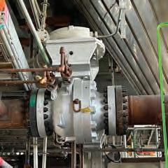


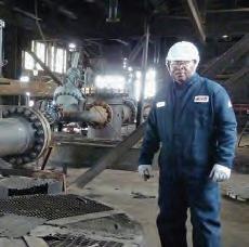


DV-4 Switching Valve

Continuous innovation for delayed coking applications


most trusted severe service technology company.
Service Valves
& Reliability
The
Severe
Service
Surface Technology
Systems & Consulting

56 April 2024 HYDROCARBON ENGINEERING
Paul Evans, Nozomi Networks, discusses the challenges faced by the downstream oil and gas industry as it embraces digitisation.

The downstream oil and gas industry is a critical component of the global economy. There is no denying that digitisation of operations has created tremendous opportunities such as increased productivity, lower costs, and enhanced profitability. However, the challenge is that connecting operations and the business enterprise has opened organisations up to a litany of cybersecurity risks. The increased use of automation and remote monitoring has increased the attack surface, making it necessary to take appropriate security measures to guarantee uptime.
For oil and gas companies, maintaining operations is crucial to their success, particularly for those in the downstream sector. The risk of downtime extends beyond maintenance concerns – they are extremely vulnerable to cyberattacks. The oil and gas industry was the fifth most targeted sector by ransomware alone, according to a recent study. The increased security measures that are now required have the potential to identify cybersecurity risks that increase the need for downtime while the issues are resolved in a safe manner. Yet in understanding this growing risk, there are ways to mitigate it.
The vulnerabilities of operational technology
Operational technology (OT) refers to the hardware and software systems used to monitor and control industrial processes. These systems are used extensively in the downstream oil and gas industry to manage everything from pipeline flow rates to refinery temperatures. The infrastructure is often dispersed and includes remote stations and legacy technology with different capabilities that are being integrated into the IT infrastructure.
A substantial challenge lies in the historical development of OT systems, which often predate the widespread availability of the internet. Originally designed to operate in isolation, these systems frequently lack fundamental security features such as encryption and authentication. This vulnerability arises from the fact that many OT systems were initially designed with serial-based connections, which have since been replaced with IP-based connections. Whilst this transition has been a crucial step towards helping operators bridge the capabilities gap between these two domains and gain greater situational awareness, there is a certain irony that the greater use of technology has become both the cause and solution to growing vulnerability for the sector. Visibility does not necessarily lead to detection and detection does not necessarily lead to the right response.
Therefore, whilst this transition has enhanced automation and efficiency, the new vulnerabilities it has created are not fully comprehended by many companies. This can have severe consequences for the industry if left unchecked. Moreover, the intricate nature of these systems complicates the implementation of updates and patches, given their essential role in maintaining the seamless operation of oil and gas facilities. The reluctance to introduce changes originates from the potential financial consequences of any downtime.
For instance, human machine interfaces (HMIs) linked to remote terminal units (RTUs) – especially those influencing volumetrics on pipelines – are considered to be one of the most vulnerable. HMIs and RTUs were designed with a focus on functionality rather than robust cybersecurity measures. The shift from serial-based to IP-based connections, while enhancing automation, concurrently introduced new vulnerabilities not fully
April 2024 57 HYDROCARBON ENGINEERING
comprehended during the original design. Given that these interfaces directly impact the flow rates and operations of critical infrastructure like pipelines, any compromise in their security poses a significant risk, potentially leading to operational disruptions and environmental consequences.
Evolution of networks and IoT components
Another challenge facing the downstream oil and gas industry is the evolution of networks and the increasing use of IoT components. As previously mentioned, OT systems were conceived for isolated operation, so integration of IoT components introduces a paradigm shift by expanding connectivity. The infusion of IoT devices, with their ability to gather and exchange data over the internet, enriches OT systems with real-time insights and enhanced functionality.
Accurately documenting the network and asset infrastructure of a supervisory control and data acquisition (SCADA) system like a long-distance pipeline used to be time-consuming and difficult, especially in terms of keeping it up to date. Now, due to technology advances, it is easier to implement passive industrial network monitoring that automatically provides real-time network visualisation and asset discovery.
The same solutions can provide early detection of operational problems and cybersecurity risks, and across critical industries the number of IoT components is also increasing, and networks are changing. This evolution of networks and the increasing use of IoT components creates new vulnerabilities that must be addressed. Every time a new asset is attached to the network, the potential entry points for cyber threats increase. The multitude of IoT components, often with diverse communication protocols and varying security postures, adds another layer of vulnerability to OT systems.
Companies must not only grapple with securing legacy systems, but also address the evolving risks associated with the integration of modern technologies like IoT. Ensuring the security of each IoT component becomes crucial, demanding robust measures to safeguard against unauthorised access, data breaches, and potential disruptions to critical processes.
In order to effectively tackle the challenges that arise with the deployment of IoT devices, it is crucial for organisations to have a specialised team equipped with the necessary skills to implement and sustain the technology. However, there is currently a shortage of cybersecurity experts on a global scale, which is particularly problematic across the oil and gas industry where there are high numbers of temporary workers and retiring baby boomers. As with many industries, there is a growing problem of a digital and tech skills gap and sourcing professionals who understand industrial control systems, IT systems and related security is not an easy silver bullet. Yet, while finding and hiring cybersecurity talent can be challenging, by utilising technology that automates monitoring and threat detection for OT and IoT networks, organisations can maintain their reliability and cyber resiliency even amidst workforce changes.
Ways to navigate OT security challenges
Navigating the challenges and securing the assets starts with truly comprehending the industry’s unique needs and crafting
solutions, teams, and strategies that align with its complexities. The challenges faced by this sector go beyond standard business operations; they extend to potential health and safety impacts if a misstep occurs. While IT assets are undeniably crucial, the criticality of OT assets takes precedence, as any loss of control in this domain can unleash consequences on a scale that is not only challenging to recover from, but may also have far-reaching ramifications. This necessitates a shift from contemplating ‘if it can happen’, to engaging in a proactive dialogue about what will happen if it occurs.
Given the unique characteristics of OT and IoT systems, it is impossible to conquer every cybersecurity challenge. Instead, companies must focus on the priorities and have risk-based conversations with the board and management. By carrying out a risk analysis, companies can make the biggest impact to reduce the overall portfolio of risks that an organisation has. They can then focus their limited budget and time on the most critical assets that have the highest risk and potentially the highest probability of vulnerability.
Another factor worth mentioning is embracing the changes and following the progress by adopting new technologies and upgrading the existing ones. This is not only crucial for improving efficiencies and decreasing costs, but also helps to increase visibility of the assets and to stay ahead of the threat actors by ensuring greater protection.
For example, cloud computing for OT systems of downstream oil and gas for security reasons was previously advised against. However, the role of cloud computing in cybersecurity is now becoming increasingly important. Cloud computing affords the ability to outsource a non-core competency with greater capacity (both computationally and storage-wise) and has become a more cost-effective option as the cost of infrastructure has lowered significantly. This technology effectively supports AI technologies such as machine learning, and the major cloud providers have become extremely proficient in cybersecurity, making cloud computing a viable option for OT systems. Therefore, by embracing cloud computing, companies can reduce their risk profile and improve their ability to manage data on a different level.
The downstream oil and gas industry faces significant cybersecurity challenges as it embraces digitisation and integrates OT and IoT systems. The vulnerabilities of legacy OT systems and the increasing use of IoT components create new risks that must be addressed to ensure uptime and prevent potential environmental and safety issues. Companies must focus on risk-based conversations with their board and management to mitigate any concerns caused by limited budgets and time on the most critical assets.
New technologies have, without a doubt, enabled a more streamlined and cost-predictive approach for downstream oil and gas businesses. Yet its growing use has also created greater risk to day-to-day business. Creating an in-house team to navigate risk is costly and hard to source in the current talent ecosystem. In 2024, cybersecurity can safely be outsourced to trusted experts who know how to pre-empt and disarm risk by working as partners, not mere suppliers. By working with those who understand the complex and evolving industry needs, and crafting solutions, teams, and strategies that align with its complexities, organisations can navigate these challenges and secure their assets effectively.
April 2024 HYDROCARBON ENGINEERING 58

Mary Sebastin and Saltanat Mashirova, Honeywell OT Cybersecurity, explain why cyber-physical risk assessments are essential in protecting petrochemical and oil and gas facilities from cybersecurity threats.
In the summer of 2017, industrial companies received a huge jolt when aggressive malware targeted the safety instrument systems (SIS) controls of a petrochemical plant in the Middle East. This was different than any attack against industrial control systems (ICS) detected in the past. Named Triton, the malware was the first attack designed to specifically infiltrate production facilities’ safety systems.1 The attack awakened many companies to how new cybersecurity threats can shut down production while potentially creating serious risks to people in and around a plant.
The capability to disrupt production in oil and gas facilities is not new. With the increasing connections of information technology (IT) and operational technology (OT), and with newly designed cyber-physical systems, the risks of such disruptions have increased. A 2023 report by Honeywell found that almost 82% of all malware can disrupt crucial industrial operations.2
Disruptions can be costly, as companies can lose huge amounts of money per hour during an unplanned shutdown. Cyber attacks on petrochemical plants can be financially devastating for the plant owners and can have significant negative impacts on society. An attack can lead to the disruption of essential services. In a worst-case scenario, an attack can cause a security incident that severely harms employees, community members, and the surrounding area.
It is not a coincidence that OT-targeted attacks have increased as investments in digitalisation have accelerated.3 As many petrochemical plants pour capital into digitalisation, the connectivity provides a larger attack surface for bad actors. Additionally, many organisations continue to use legacy devices that may be decades old. These legacy assets often have well-known vulnerabilities that can no longer be
April 2024 59 HYDROCARBON ENGINEERING
addressed with patches and lack security measures more common in current software and firmware.
These factors create an environment that exposes more cyber attack opportunities. It is essential that companies continue to invest in cybersecurity resiliency programmes. To do so, the companies must better understand how a cyber-physical attack can impact their process operations and safety.
Cyber-physical risk assessment
Without understanding risks, companies are almost positioning themselves like 16th century sea captains sailing at dark around an unmapped coast without knowledge of rocky reefs. They might avoid some of the dangers, but at some point, they will hit a rocky outcropping that is big enough to rip a hole in their vessel. Cyber attacks can strand organisations and potentially sink them as well.
In the process industry, the understanding of risks related to process safety is well established. Process safety professionals commonly use the hazard and operability study (HAZOP) and layers of protection analysis (LOPA) methods. These two methods are designed to focus on assessing how an accidental event that causes a process incident can occur and what safety precautions need to be taken to reduce the risk of the negative consequences to a level that corresponds to the company’s internal and external tolerable risk levels.
The challenge arises when the cause of the process incident is no longer an accidental event, but a series of deliberate actions by malicious actors designed to cause harm.
How can these actions be included in a traditional HAZOP or LOPA?
This can be achieved by examining hundreds of cyber attack scenarios against industrial control and safety systems, identifying process loss scenarios and existing protections that cyber attacks can manipulate, whilst also considering the asset criticality, dependency, and interconnections.
These scenario-based risk assessments are used to evaluate cyber-physical risk by linking the consequences of a
cyber attack (i.e., functional deviation) from cyber attack scenarios with process loss scenarios. Semi-quantitative risk assessments such as these are designed to provide companies with quantitative results regarding the cybersecurity resilience of a given system.
For example, companies can model cyber attack scenarios against process automation functions. With this type of analysis, companies can estimate the attack severity based on the impact on the process automation function, such as loss of intended design or operation. The result is a calculated value expressed as a risk priority number.
Why does risk priority matter?
Risk priority is designed to help organisations identify the highest-priority risks that must be addressed. By design, the risk priority number should correspond to a matrix that compares probability with severity. The higher the priority number, the greater the risk. The probability ranges from current to unpredictable, and the severity from catastrophic to negligible.
When companies model cyber attack scenarios against process losses, it is recommended that they factor in the impact of cybersecurity attacks on the causes and protective measures in LOPA scenarios. In this type of analysis, companies should be able to use the target mitigated event likelihood (TMEL) risk criteria to determine the risk priority. The risk categories for process losses include individual, societal, environmental, and financial. Each category has a different range. As an example, individual risk is rated from fatality to minor injury, whereas environmental risk is rated from environmental disaster to no impact.
Honeywell’s cyber-physical risk assessment is designed to estimate the quantitative success rate of a cybersecurity attack by considering the design of the process automation system and actions of threat actors with unique profiles who use different tactics, techniques, and procedures (TTP). Honeywell also considers the frequency of the threat actions’ triggering event, which is statistically dependent on the TTP frequency. The summary provided in Figure 1 is designed to illustrate how all of the considered risk estimates can come together as part of the cybersecurity hazard and operability study.
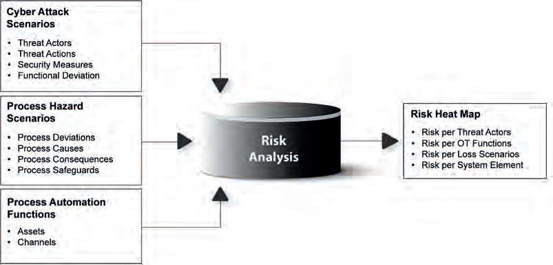
Observations from assessments
For more than a decade, Honeywell’s OT cybersecurity teams have worked with industry teams to conduct cyber-physical risk analyses that go beyond traditional
April 2024 HYDROCARBON ENGINEERING 60
Figure 1. Cybersecurity HAZOP assessment.

Capturing green opportunities
Carbon capture and storage or utilization (CCS/CCU) is a key strategy that businesses can adopt to reduce their CO2 emissions. By selecting the right technologies, pressing climate change mitigation targets can be met while benefitting from new revenue streams.
Sulzer Chemtech offers cost-effective solutions for solvent-based CO2 absorption, which maximize the amount of CO2 captured and minimize the energy consumption. To successfully overcome technical and economic challenges of this capture application, we specifically developed the structured packing MellapakCC™. This packing is currently applied in several leading CCS/CCU facilities worldwide, delivering considerable process advantages.
By partnering with Sulzer Chemtech – a mass transfer specialist with extensive experience in separation technology for carbon capture –businesses can implement tailored solutions that maximize their return on investment (ROI). With highly effective CCS/CCU facilities, decarbonization becomes an undertaking that can enhance sustainability and competitiveness at the same time. For more information: sulzer.com/chemtech

Visit us at ACHEMA in Frankfurt Hall 4 Stand D48
HAZOP or LOPA assessments. Each site is unique, but there are some commonalities:4
n On average, 50% of process loss scenarios can be caused by an intentional cyber attack.
n In two of three cyber attack scenarios that could lead to fatalities, adequate cybersecurity countermeasures were not taken.
n Protecting SIS from cyber attacks is critical, as 98% of scenarios that could lead to fatalities involved an attack on the SIS.
n An insider threat with malicious intent is likely to cause cyber incidents which have serious impact.
n Functions such as advanced process control, open platform communications (OPC), historian, alarm server, remote server, etc. can be initial foothold(s) which can lead to similar impacts on process control scenarios.
No single cybersecurity countermeasure alone can help meet the risk criteria, so a thorough defence and solid understanding of countermeasures (e.g., monitor, detect, protect, recover) are essential.
Conclusions
Oil and gas, chemical, and other industrial facilities have used process safety risk assessments for decades to understand what precautions need to be taken to help reduce the risk of serious incidents. Unfortunately, these assessments are no
longer sufficient unless the impact of intentional cyber attacks is considered and thoroughly analysed.
Using results from a qualitative cybersecurity risk assessment with a number-based process safety risk assessment is usually not fully effective. However, with the right focus on what is known, a semi-quantitative cybersecurity assessment can be performed and tightly integrated into a facility’s otherwise comprehensive HAZOP or process hazards analysis (PHA).
The result of such an assessment should be identification of what countermeasures can help reduce the risk of a process incident caused by a cyber attack to a tolerable risk level. This is extremely valuable in helping to create a more effective OT cybersecurity programme.
Ultimately, companies must strengthen their cyber defences and focus on the essentials. A comprehensive cybersecurity risk reduction programme that meets their goals should be based on regular OT cybersecurity assessments.
References
1. GIBBS. S., ‘Triton: Hackers Take Out Safety Systems in Watershed Attack on Energy Plant,’ The Guardian, (15 December 2017).
2. ‘Industrial Cybersecurity USB Threat Report 2023’, Honeywell Cybersecurity team, (November 2023).
3. ALLEN, J., ‘Digital Transformation and the Expanding Attack Surface of Critical Infrastructure’, Government Technology Insider, (14 November 2022).
4. Data collected and analysed by Honeywell OT Cybersecurity Operations team, (2023).
BELIEVING SEEING IS
Take a look at our ABC Certificate. It shows our circulation has been independently verified to industry agreed standards.
So our advertisers know they’re getting what they paid for. ABC. See it. Believe it. Trust it.

www.abc.org.uk

Avoiding the cybersecurity problem is no longer a viable strategy, but putting protections in place is more straightforward than it seems.
Alexandre Peixoto, Emerson, explains.
For years – arguably even decades – many operational technology (OT) teams have practiced cybersecurity by obscurity. Systems were explicitly air-gapped to segregate every level of OT operations, and to provide the best protection against intrusion and interruption. Systems that never saw the outside world never needed to fear external attacks.
April 2024 63 HYDROCARBON ENGINEERING
Today, however, the OT paradigm is changing. The most successful organisations around the globe are embracing connectivity to the wider world to unlock the operational efficiencies that drive competitive advantage in a global marketplace. These companies are implementing new technologies that unlock seamless data mobility from field to edge to cloud.
Nowhere is this more apparent than in the hydrocarbon processing industry, where technologies are rapidly changing to help organisations improve performance and continue to thrive in an unstable market. Successful organisations need connectivity to drive critical visibility and analytics both at the edge and in business systems, but navigating this change means finding new ways to ensure systems are cybersecure.
The new normal
Gone are the days where oil and gas, chemical, and petrochemical operations had deep benches of highly experienced personnel to drive efficient operations. Now, experienced analysts, operators, and technicians command a premium – in the rare instances they can be found. As a result, today’s operations run very differently than those of just a decade or two ago. In many places, small crews of personnel are centralised and cover a wider area than ever before. Many of those individuals are coming from a new generation raised on constant

connectivity and instant access to data, and workers of all ages require these features to perform their work efficiently (Figure 1).
To meet the needs of this diverse workforce, data must be highly mobile. Edge solutions must contextualise data and deliver it to mobile devices in the field – and to business analytics systems in corporate offices – for constant awareness of plant health, instant mobilisation of resources, and enhanced collaboration, all to drive operational efficiency. This new connected, mobile workforce is the solution to increasing efficiency in the modern era, but it cannot work when companies must fear that bad actors may be able to insert themselves in the middle of the communication networks and wreak havoc.
Many organisations know they need to move in the direction of a boundless automation future, but they also see the ever-increasing number of cyberattacks now targeting OT assets. They know cybersecurity solutions can enable connectivity, but the same shortage of personnel necessitating change also impacts an organisation’s ability to properly assess their need and build a roadmap for success. And even for organisations that may still have a deep bench of expert personnel, those people rarely have the time to commit to researching, identifying, implementing, and maintaining the cybersecurity solutions that will fit their unique needs, especially when threats change seemingly constantly.
But while implementing and maintaining secure yet connected operations is not a simple task, neither is it an insurmountable one. To succeed, teams must start by charting their journey, while also not being afraid to make course adjustments along the way. Several strategies can help them start and maintain those goals.
Define a starting point
The cybersecurity journey is key to navigating the external threats that can disrupt operations. Successfully navigating that journey requires teams to understand their necessary cybersecurity architecture and to know the steps they need to take. Air-gapping has long been a non-starter for OT systems, but interconnecting enterprise networks to everything else without a clear cybersecurity strategy is not an acceptable approach either.
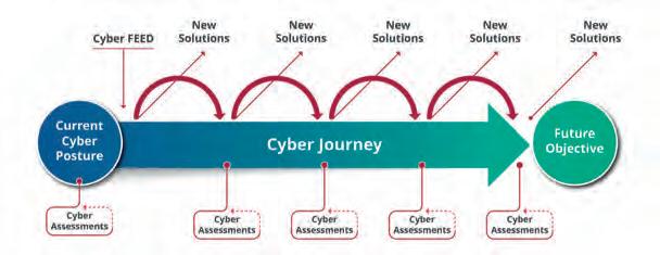
One of the first steps of a cybersecurity journey is knowing the organisation’s starting point. Every organisation – and in many cases each plant within an organisation – starts from a different place. A well-executed cybersecurity assessment can help teams successfully map out the key elements of their entire journey, while keeping in mind that a cybersecurity journey is an evergreen process because the threat landscape is evolving continuously.
For example, one of the key ways to identify critical steps on the cybersecurity journey is to understand the organisation’s
April 2024 HYDROCARBON ENGINEERING 64
Figure 1. Modern digital workers expect constant connectivity, in the control room and in the field, for enhanced decision support.
Figure 2. Cybersecurity is not set-and-forget. Any implemented solutions should be regularly re-evaluated for effectiveness via scheduled cyber assessments.
existing cybersecurity posture. For some organisations, this might simply mean the development of policies and procedures that OT system users must follow. For others, it might be a complex environment of previously installed information technology (IT) solutions, each with varying levels of effectiveness. A cybersecurity assessment can help teams put a frame around existing solutions to determine what is working and what is not, and to show what is missing (Figure 2).
Define needs
One of the most common missteps on a cybersecurity journey is trying to find and implement solutions before defining the organisation’s overall cybersecurity needs. Exciting, new cybersecurity solutions emerge each day, and it can be tempting to think that one appliance will fit every need across the environment, but this is rarely true. To implement solutions that work over the system’s lifecycle, teams need to define the ‘why’ of their cybersecurity journey before they define the ‘how’.
Need definition must consider the unique requirements of operating cybersecurity solutions in an OT environment. Whether an organisation has a deep bench of expert IT personnel, or a single person managing all of the company’s technology, OT typically needs tailored solutions. All-in-one solutions engineered for the flexibility of IT systems typically do not function well within OT. Moreover, companies designing solutions


for IT environments are rarely prepared to properly support OT issues. When defining need, it is important to consider the uptime requirements, safety concerns, and business drivers that are unique to OT. Although having similar cybersecurity goals, IT prioritises data confidentiality and record keeping, while OT prioritises system availability and safety.
Build the roadmap
After OT teams have defined their unique cybersecurity and business needs, they can begin to lay out the architecture to meet those requirements. As a team builds out its cybersecurity implementation roadmap, it is important to consider not only the solutions they will put in place, but also a plan to monitor those solutions. For example, an intrusion detection system reporting to a rarely used workstation is unlikely to draw the quick attention necessary when an attack occurs. Similarly, antivirus solutions put in place but never checked will have a very short window of efficacy.
To address these types of issues, organisations should develop written policies for monitoring and response of cybersecurity systems to ensure they will work properly and at full efficacy across their entire lifecycle. Patching is critical for cybersecurity solutions as well, so keeping these systems up to date is essential. Not implementing these and other best practices will hinder the overall cybersecurity posture of protected systems.


EXHIBIT AT CANADA’S NATIONAL ENERGY EVENT June 11-13, 2024 Calgary,
30,000+ ATTENDEES 500+ EXHIBITING COMPANIES 400+ PRESENTING SPEAKERS 50+ HOURS OF EDUCATION SCAN TO BOOK YOUR STAND globalenergyshow.com
Alberta
Build a cybersecurity culture
Once a path is defined and the OT team begins putting architectures and monitoring policies in place, organisations need to focus on compliance. The three pillars of cybersecurity – technology, process, and people – are all interlinked. The right technologies and processes must be in place to ensure security, but people must also be trained to use the technology properly and understand the value of a cybersecurity mindset.
Cybersecure behaviour is not intuitive – it is learned. A key part of any cybersecurity journey should be developing training to teach personnel how to properly use the new solutions that are put in place. Moreover, part of that training should help users understand how a cybersecure operation protects and supports them. When technology, process, and people are all working together, users are more alert to how global changes may impact their ability to operate securely, and how that secure operation improves their own lives.
Users who see personal value are more likely to faithfully follow processes and procedures to help keep the organisation secure. With the right technology in place to help them maintain cybersecure operations, users can meet the organisation’s benchmarks much more easily (Figure 3).
Identify key partners
Many of today’s OT groups are choosing not to define, develop, and implement their cybersecurity journeys alone. With this approach, it is very difficult to stay up-to-date with the most current threats and their mitigations, and as more governments around the world increase cybersecurity regulation, keeping up with the mandates also becomes increasingly complex.
To address this and related issues, many of today’s most successful organisations are partnering with automation solution providers who operate in both the OT and IT space to relieve the burden of developing a cybersecurity journey that fits their unique OT needs. Organisations partnering with experienced automation solution providers can count on expert guidance to help them select, install, maintain, and monitor the

technologies that will work best for their unique environment.
Prepare for the future
In contrast to the isolationist cybersecurity policies of the past, modern cybersecurity solutions in the OT space are designed to enable connectivity, rather than prevent it. Organisations moving toward connectivity strategies enabling widespread OT connectivity and real-time monitoring have created a fundamental shift in the way teams approach security – requiring them to thread the needle between uber-security and full convenience. Concepts like the zero-trust network architecture are securing identities, data, applications, networks, etc, in a more customised way, enabling enhanced connectivity and monitoring in real time.
To meet this new normal, both OT teams and their partners are considering more forward-thinking strategies. A team that needs to wait for every solution to be fully vetted, readily available, and tested by every major customer in the market will always be behind. Instead, modern users need ways to implement the pieces of larger cybersecurity initiatives, like zero trust, today, and then continue to evolve those solutions over time.
To meet this need, automation solution providers are now exploring ways they can plot zero trust architectures that will not be executed in a single year. They know the direction of the architecture and are building it piece by piece. As those pieces emerge, they can be implemented to update the existing architecture of their users. This agile development will help meet new threats as they arrive.
And while this new flexible model does create some uncertainty, it is also far more effective at adjusting to meet emerging threats, regulations, and shifting control architectures by empowering OT teams to meet their ever-changing security needs, without having to rip and replace entire architectures every time a significant new threat emerges. These types of cybersecurity solutions will be both more adaptable, and more cost-effective.
The most successful journey starts today
A rise in incidents around the globe has put the spotlight on OT cybersecurity, and few organisations still think they can hide from threats. Instead, forward-thinking organisations are taking steps to build a strong cybersecurity posture by shoring up defences as efficiently and effectively as possible. Doing so not only creates a work atmosphere that protects personnel and production from harm, but also fosters a more agile environment, unlocking the tools that allow OT teams to do more with less by driving better visibility and collaboration across their enterprise.
The tools and strategies necessary to successfully execute a cybersecurity journey are available today, but the journey takes time. The sooner an organisation starts to build its roadmap, the sooner it will be ready to operate in the modern economy.
April 2024 HYDROCARBON ENGINEERING 66
Figure 3. Comprehensive training highlights the value of cybersecurity processes and procedures, facilitating buy-in from personnel across the organisation.
Hydrocarbon Engineering presents a selection of the most advanced sulfur technologies and services that are currently available to the downstream sector.
AMETEK Process Instruments
AMETEK Process Instruments has released an innovative photometric analyser designed to measure gas species at various sample points within gas processing, refining and steel/coke amine plants and sulfur recovery units (SRUs), using ultraviolet (UV) spectroscopy, while also supporting the addition of other measurement technologies. The 993X is a versatile gas analyser, capable of continuously measuring up to seven components utilising multiple measurement technologies, without consumables.
UV measurements of H2S, SO2, NO, NO2, NOx, COS, CS2, and NH3 utilise AMETEK optical bench configurations that have been proven in challenging applications for decades. Drift and noise are minimised through the use of highly

focused emission lines and a temperature-controlled optical bench, which provides stability when ambient temperatures fluctuate.
Because it supports the use of IR sensors and a thermal conductivity detector (TCD), the 993X is also capable of measuring known components that do not absorb UV light, such as CO2 and H2
Designed for installation inside or outside of a temperature-controlled enclosure, the 993X has an ingress protection (IP) rating of IP66 and NEMA 4X, protecting against harsh operating environments.
The wall mountable 993X, with integrated heater (capable of maintaining sample temperatures of up to 165°C, to prevent the formation of liquids) and sample conditioning system, is designed to operate unattended.
April 2024 67 HYDROCARBON ENGINEERING
Delta Controls Corp.
Delta Controls Corp. is an internationally recognised expert in the design and manufacturing of process instrumentation. Delta Controls’ instrumentation design expertise allows the company to provide innovative and reliable solutions for demanding applications such as sulfur recovery units (SRUs).
The company’s newest product for sulfur recovery service is the Model HRC ProSpection video monitoring system developed for Claus reactors. It provides continuous online monitoring of the interior of a Claus reactor. The HRC probe places the camera lens inside the thermal reactor directly at the refractory hot face, allowing for a wide-angle view of critical vessel components such as the burner, refractory, and tubesheet.
IPCO
IPCO is a global industrial process company developing high productivity solutions across a range of applications including sulfur solidification and handling. The company offers a comprehensive range of systems and services to the oil and gas industry, ranging from leading sulfur solidification equipment to end-to-end solutions covering everything from receipt of molten sulfur to storage and loading of solid material.
For small to mid-size capacity operations, IPCO’s Rotoform system is a single step, liquid-to-solid process that delivers SUDIC premium product pastilles and environmentally friendly operation. The system also offers a predictable high bulk density, which is an advantage for
Merichem Technologies
The US Environmental Protection Agency (EPA) will begin significantly strengthening limits on fine particle matter (also known as soot) – one of the US’ most widespread deadly air pollutants. Refineries, power plants and other polluting facilities will be mandated to cut soot emissions to reduce deadly air pollution. Some of the compounds in soot, primarily sulfur dioxides and nitrogen oxides, are precursors to acid rain, which can acidify lakes and rivers causing havoc for a variety of different ecosystems.
Merichem Technologies (based in Houston, Texas, US) has advanced the technology of sulfur reduction and perfected the process of sulfur removal. Merichem’s LO-CAT
Optimized Gas Treating Inc.
Following development of ProTreat®, the first fully mass-transfer rate-based simulator for amine gas treatment, Optimized Gas Treating Inc. (OGT) expanded into almost all facets of downstream gas treating, including glycol dehydration, absorption by physical solvents, caustic treating, and sulfur recovery marked by the release of SulphurPro® in 2016.
When developing SulphurPro, the original philosophy underlying ProTreat was retained to ensure the simulator is
The Model HTX Thermocouple is internationally recognised as a premier purged thermocouple for measuring SRU temperatures. The Model HTV Unpurged Thermocouple provides accurate temperature measurement from turnaround to turnaround without a purge system. The Model HIR Pyrometer employs a dual-wavelength infrared ratiometric measurement system that is unaffected by partial nozzle obstructions or coated windows.
Delta Controls’ sulfur instrument products are installed in over 155 sulfur plants worldwide. These products are engineered to provide improved process uptime and reduced maintenance, resulting in lower maintenance costs for SRU plant operations.
storage and transportation. This is the world’s most widely used sulfur granulation process with more than 700 installations to date.
For higher capacity requirements, the IPCO SG drum granulation system is an automated process capable of processing up to 2000 tpd of sulfur – making it the world’s highest capacity sulfur drum granulator.
Bulk materials handling solutions include everything from conveyor components to rectangular/circular stackers and reclaimers, as well as loading solutions for truck, rail and ship.
IPCO can undertake end-to-end project management from feasibility studies and front end engineering design (FEED) through to complete engineering procurement and construction (EPC) packages.
is a highly trusted, green solution for converting hydrogen sulfide (H2S) to elemental sulfur. The LO-CAT’s Auto Circulation design has a small carbon footprint yet achieves very high removal efficiencies (>99.9%). There are no liquid waste streams, so it does not require treatment and disposal.
THIOLEX is also a Merichem technology that effectively removes mercaptan compounds (RSH), H2S, carbon dioxide (CO2), carbonyl sulfide (COS), and elemental sulfur. The company’s FIBER FILM Contactor, which is used in conjunction with THIOLEX, creates a significantly larger interfacial surface area, using minimum mixing energy, allowing for enhanced microscopic diffusion and a continuous renewal of the aqueous phase.

truly predictive. Each equipment item in the Claus SRU has been carefully developed to include fundamental reaction kinetic rates and conductive, convective, and radiative heat transfer.
The thermal reactor uses reaction kinetics to calculate accurate ammonia destruction, hydrocarbon destruction, and COS/CS2 formation. The waste heat boiler, steam reheater, and condenser operations all use rigorous heat transfer rates to accurately calculate outlet temperatures from exact equipment dimensions. Both the sulfur
68 April 2024 HYDROCARBON ENGINEERING
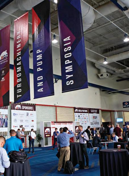


BRINGING EDUCATION AND INDUSTRY TOGETHER.
SHORT COURSES: AUGUST 19, 2024
SYMPOSIA: AUGUST 20-22, 2024
GEORGE R. BROWN CONVENTION CENTER • HOUSTON, TX
The Turbomachinery & Pump Symposia is recognized worldwide as the industry’s must-attend event. Connect with more than 4,900 delegates, meet with leading suppliers, observe product demos, and get answers to your technical questions. We look forward to seeing you in Houston!
4,945 ATTENDEES
323 EXHIBITING COMPANIES
53 COUNTRIES
TPS.TAMU.EDU #TPS2024
HOSTED BY
converter and the hydrogenation reactor contain extensive reaction sets to calculate the kinetic reaction rates of both the Claus reactions and the hydrogenation reactions. These models also include catalyst ageing and poisoning to give the most accurate representation of the catalyst in a plant.
Servomex
Acid gases such as hydrogen sulfide (H2S) and carbon dioxide (CO2) must be removed from natural gas to prevent safety issues such as pipeline corrosion. Accurate gas analysis helps to ensure these contaminants are removed effectively, protecting product quality and safeguarding pipelines.
The Claus process allows elemental sulfur to be extracted from the gaseous H2S, allowing it to be used in chemical manufacturing, medical, and agricultural applications. Tail gas treatment turns unconverted sulfur compounds back into H2S and recycles it back into the sulfur recovery unit, for more efficient recovery.
Servomex has many years of experience in empowering productivity and efficiency in this sector, supporting these
Shell Catalysts & Technologies
Shell has been operating and actively developing technologies for sour gas facilities since the 1960s. Much early development was in North America, but the fastest growing area is now the Middle East. The increasing requirement to meet growing energy demand sustainably means integrating technologies for CO2 capture, sequestration and enhanced oil recovery (EOR) while minimising SO2 emissions.
Shell has supported numerous Middle East operators with innovative solutions to make sour gas production more sustainable. Shell’s gas treating solutions, such as Sulfinol*-X and ADIP* ULTRA, and the sulfur recovery and tail-gas treating technologies such as Shell Claus off gas treating (SCOT*) and SCOT ULTRA, have been applied in many of the region’s largest projects over several decades. Shell continually strives to make these technologies more
Unicat Catalyst Technologies LLC
Dedicated to revolutionising catalyst technology for enhanced customer, financial, and environmental performance, UNICAT Catalyst Technologies LLC leads the charge in sulfur removal solutions. The company provides robust supply chain security through several key supply sites across the globe, ensuring short delivery times and a reduced carbon impact from transport.
UNICAT prioritises listening and learning from its customers, shaping its innovation pipeline to deliver tangible value across the industry. Its sustainable catalyst technologies not only improve operational efficiency but also reduce environmental impact.
With a keen focus on supply chain security, UNICAT guarantees reliable access to essential purification products
SulphurPro is a complete and comprehensive Claus SRU model. By using state-of-the-art reaction kinetics and rigorous heat transfer, sulfur plant engineers and designers can now get an extremely accurate representation of their plant to help make important decisions for optimisation, new projects, and troubleshooting.
applications with innovative and reliable gas analysis. The rugged and flexible SERVOTOUGH SpectraExact 2500 photometric analyser uses infrared and gas filter correlation sensing technologies to provide measurements of CO2, H2S, and water in amine for control and quality measurements.
Designed for ease of use, the SpectraExact 2500 is suitable for demanding process applications, including monitoring continually flammable sample streams in hazardous areas.
In addition, the SERVOTOUGH Oxy 1900 and OxyExact 2200 non-depleting paramagnetic analysers can be applied in a safety system to monitor oxygen in natural gas during storage and transportation.
efficient, achieve tighter specifications and lower energy consumption. One of the key technologies in its portfolio is the CANSOLV* CO2 Capture System. This technology has recently been selected for a key capture project in the region that has taken final investment decision (FID) in 2023 and should be in operation by 2027.
These technologies are helping those projects to meet their carbon intensity mandates and SO2 emissions limits, and ensure resilient and sustainable production.
With more than 60 years of sour gas processing experience and its continually evolving process technologies, Shell Catalysts & Technologies is uniquely positioned to ensure sour gas resource holders contribute sustainably to meeting global energy demand.
*Sulfinol, ADIP, SCOT and CANSOLV are Shell trademarks.
from strategic locations worldwide. The company’s innovative solutions elevate sulfur removal processes, fortify supply chains, and unlock growth opportunities in shaping a cleaner, more sustainable future.
UNICAT commercialised Magcat® Textured Sphere reformer catalysts and its UK counterpart was awarded the Queens Award for Enterprise – Innovation in 2022. This has been followed by transformative innovation to Advanced Filtration System (AFS) technology, to significantly improve the protection of hydrotreaters, delivering step change uptime benefits. UNICAT is continuing its innovation launch process with new pre-reforming catalyst technology, which is focused on significantly enhancing bed lifetime and performance. This will be followed with more revolutionary technology in pressure swing adsorption (PSA).
70 April 2024 HYDROCARBON ENGINEERING


Worley Comprimo
Sustaining the world for generations to come through technological and environmental innovation, Worley Comprimo offers a broad gas processing and sulfur recovery technology portfolio. Its solutions provide the lowest CAPEX and OPEX levels while meeting local sulfur recovery efficiency regulations.
Established in 1924, Worley Comprimo is celebrating its 100th anniversary in 2024. Ever since the 1950s, its technology has been featured in more than 1200 sulfur recovery units (SRUs). With five execution centres and a comprehensive global expert network, its customers enjoy responsive technical support and access to over 100 dedicated sulfur experts.
Worley Comprimo’s sulfur degassing technologies cover the full range of performance guarantees and

applicability. Notably, its portfolio includes a technology that can be installed in both sulfur pits and sulfur collection vessels, ensuring compliance with less than 10 ppmw H2S in the product sulfur. This is an ideal solution for very low-emission SRUs, where vent streams from the degassing unit do not require complicated controls to the main burner. Simultaneously, it offers an easy-to-implement, cost-effective approach to reducing emissions from sulfur loading stations in smaller SRUs.
This latter technology, marketed as the High Efficiency Sulphur Degassing Process, was installed and tested at a refinery in the US. The results were transformative, enabling a shift in sulfur loading operations to a degree where breathing masks are no longer required.

April 2024 HYDROCARBON ENGINEERING 72 Page Number | Advertiser 62 | ABC 31 | AMETEK Process Instruments 47 | AUMA 21 | Black & Veatch OBC | Endress+Hauser 02 | Eurotecnica 65 | Global Energy Show Canada OFC & 12 - 13 | Halliburton Multi-Chem 27 | HTRI 41 | IPCO 55 | MOGAS Industries Inc. 11 | Optimized Gas Treating, Inc. 51 | OsecoElfab 22, 52 | Palladian Publications IBC | Paratherm 17 | Alleima 33 | Servomex 07 | Shell Catalysts & Technologies 61 | Sulzer Chemtech 43 | Tracerco 25 | Trillium Flow TechnologiesTM 69 | Turbomachinery & Pump Symposia 71 | UNICAT Catalyst Technologies, LLC IFC | Union Tech 04 | Zeeco Inc. AD INDEX

RELIABLE CONSISTENT RESULTS Proven, advanced formulations ideal for your processes, industry, and applications. More and better choices in heat transfer fluids based on our over 35 years experience. www.paratherm.com 2009 Renaissance Blvd., King of Prussia, PA 19046 USA Int’l: +1 610-941-4900 Fax: +1 610-941-9191

We understand how you need to reduce complexities at your plant. CLEAN PROCESS + CLEAR PROGRESS You strengthen your plant’s safety, productivity and availability with innovations and resources. Endress+Hauser helps you to improve your processes:
With the largest portfolio of safety instruments that comply with international regulations
With applied technologies and people who have extensive industry application know-how
With access to accurate and traceable information Do you want to learn more? www.endress.com/oil-gas Visit us at RefComm 2024 Booths 48 & 49
•
•
•
